


Abstract
To address the stringent sealing requirements of specialized equipment in extreme deep-sea environments, where traditional unidirectional sealing structures often fail to accommodate complex bidirectional pressure fluctuations, this study focuses on bidirectional T-groove dry gas seals. The primary objective is to elucidate the influence of groove depth evolution on gas film lubrication characteristics. Based on gas film lubrication theory, a hydrodynamic lubrication governing equation was established. Furthermore, a compressible gas film thickness equation was proposed to characterize the stepwise evolution of the groove geometry, accurately describing the evolution of the gas film thickness with varying groove profiles. Through numerical simulations, key performance parameters—including opening force, leakage, gas film stiffness, and stiffness-to-leakage ratio—were systematically evaluated for six T-groove structures with varying depths. The results reveal a competitive mechanism between operating conditions and sealing performance: while elevated pressure enhances the hydrodynamic effect and gas film stiffness, it simultaneously increases the leakage rate. Similarly, higher rotational speeds improve load-carrying capacity but exacerbate gas flow and leakage. A comparative analysis of the stiffness-to-leakage ratio across the six models indicates that Type 4 and Type 3 achieve the optimal balance between gas film stiffness and leakage control. This study confirms that rational groove design can effectively balance the opening force and leakage rate, thereby enhancing sealing stability. Ultimately, this research uncovers the specific mechanisms by which bidirectional T-groove structures influence gas film lubrication performance, providing a theoretical foundation for optimizing the sealing structures of high-end deep-sea equipment.
1. Introduction
As engineering equipment continues to expand into extreme deep-sea environments, the sealing reliability of deep-sea submarines and various underwater operating equipment in high-pressure, low-temperature, and corrosive media has become increasingly prominent [1,2,3]. Under deep-sea working conditions, sealing devices must not only withstand immense environmental pressure but also ensure the safety and stealth of the equipment, posing stringent adaptability requirements for sealing technologies [4,5,6]. For these specialized deep-sea environments, traditional unidirectional sealing structures struggle to meet the operational stability demands caused by bidirectional pressure fluctuations [7,8,9]. Consequently, researching T-groove structures capable of maintaining superior lubrication states and sealing performance under bidirectional conditions is of significant engineering value for breaking through the sealing technology barriers of deep-sea equipment [10,11].
Current research hotspots in the field of dry gas seals primarily focus on nonlinear flow-field effects under complex operating conditions and the in-depth optimization of groove structures, aiming to break through the performance bottlenecks of traditional designs [12,13]. Based on the gas lubrication theory, Zhang et al. [14,15] designed a bidirectional T-groove dry gas seal and established the Reynolds equation for compressible gas. Through experimental tests, the effectiveness of the calculation program is verified. Ding et al. [16] developed an energy equation that includes corrections for heat transfer, gas state, and centrifugal and turbulent effects. The results show that the leakage rate increases with an increase in rotational speed and pressure. Then, it gradually increases as the rotational speed increases and increases as the medium pressure increases. Wang et al. [17] proposed a new diamond cross-section groove design to optimize the performance of dry gas seals. The results show that the diamond groove produces a stable eddy current, which enhances the hydrodynamic pressure in the gas film. With an increase in film thickness, the leakage amount increases significantly, and the combination of turbulence and slip effects results in a value nearly 50% higher than that of laminar flow. Wang et al. [18] predicted the flow pattern of a dry gas seal rotating flow field based on a three-dimensional velocity component (ellipsoidal model). The results show that the three-dimensional ellipsoid model proposed in this paper can produce more accurate results compared with the one-dimensional pipeline model and the two-dimensional ellipsoid model. Fairuz et al. [19] used CFD to study the dry gas sealing operation of supercritical CO2 under two operating conditions. The study showed that under operating conditions far from the critical point, a maximum change in pressure of 1.7%, a maximum change in temperature of 0.4%, and a maximum change in density of 1.1% were observed. Jamshidi et al. [20] investigated the influence of the geometric parameters of a DGS with trapezoidal grooves on the leakage rate and opening force in dry gas seals.
On the one hand, for extreme environments such as high pressure and high speed, researchers have introduced inertia terms and turbulence models to modify the Reynolds equation, accurately describing the flow-field instability mechanisms at the microscale [20,21,22]. Furthermore, the Virial equation of state and thermohydrodynamic lubrication models have been adopted to quantify the impacts of real gas effects and thermal deformation of the seal faces [23,24,25]. Yan et al. [26,27] studied the effects of turbulence and different flow processes on the sealing performance of supercritical CO2 (S–CO2) dry gas through theoretical calculations and experimental tests. The results show that with an increase in rotational speed and pressure, the flow in the membrane gradually turns into turbulence, and the turbulence effect has a significant impact on the leakage. Hahn et al. [28] proposed a modified Reynolds equation that considers the effects of laminar flow, turbulence and slip behavior of fluid membranes. The accuracy of the developed program was verified by comparing the simulated pressure with that in previous studies, and the measured leakage with the simulated leakage. Brunetiere et al. [29] proposed modifications to the Elrod and Ng turbulence models. The results show that the fluid flow becomes turbulent for values higher than the Reynolds number. Wang et al. [30] numerically calculated the turbulent flow field in a spiral-groove dry gas seal and used direct numerical simulation (DNS) and Reynolds average Navier–Stokes (RANS) methods to predict the velocity field characteristics in the groove and gas film.
On the other hand, to enhance the comprehensive performance of seals, researchers are dedicated to structural innovations such as variable-depth T-grooves, micro-texture composite designs, and annular grooves for leakage reduction [31,32,33]. These efforts attempt to compensate for the insufficient hydrodynamic effects and stiffness of bidirectional grooves through the precise regulation of geometric parameters [34,35]. Lu et al. [36] studied the film stiffness of spiral-groove dry gas seals and determined the film stiffness by establishing a dynamic test system. The results show the optimal values of the spiral angle and groove depth for the film stiffness: the spiral angle is 1.34 rad (76.8°) and the groove depth is 1 × 10⁻⁵ m. Badykov et al. [37,38] investigated the dynamic process of dry gas seal operation and used it to determine the stiffness and damping characteristics of the gas film. Hu et al. [39] proposed designing a special shallow-groove structure on the outer diameter of the primary ring and using signal processing to study the effects of different wear degrees and stiffness. The research conclusions emphasize the importance of integrating monitoring capabilities into the initial design phase of sealing structures.
Meanwhile, visualization techniques have been combined to reveal the evolution laws of microscopic flow fields, and multi-physics coupling analyses have been introduced to achieve the synergistic optimization of key performance metrics, including opening force [40,41], stiffness [42,43], and leakage rate [44,45]. Wang et al. [46] established a dynamic mathematical model to describe the exponential evolution of pressure gradients in dry gas seals. In addition, a comprehensive flow model is constructed using a coupled bicontinuum–discrete fracture model, and an accurate numerical solution is achieved. Ding et al. [47,48] used theoretical methods based on the compressible Reynolds equation and the energy equation considering heat dissipation to explore the temperature distribution within the gas film. The results show that the proposed theoretical calculation method can be applied to the analysis of dry gas sealing temperature, and heat dissipation is an important factor that can be used to optimize groove design in the future. Yang et al. [49] designed an ultra-clean micro-gas flow standard device with dry gas sealing characteristics. The device adopts a horizontal structure, using an O-ring on the piston for radial sealing, which is different from traditional mercury and gap seals, thereby comprehensively analyzing the dry gas sealing characteristics. Despite significant advances in dry gas seal research, systematic studies on the evolution of bidirectional T-groove structures and their effects on gas film lubrication under deep-sea conditions are still lacking. Although previous studies have optimized geometric parameters to balance opening force, stiffness, and leakage, the synergistic impacts of groove depth evolution on film pressure distribution and microscopic flow-field characteristics in extreme environments remain unclear. This study aims to clarify how groove depth evolution affects lubrication characteristics, thereby providing a rational design basis for improving sealing stability in deep-sea applications.
The geometric parameters of bidirectional T-grooves play a decisive role in determining the formation mechanism of the gas film, the pressure distribution patterns, and the flow-field characteristics. A rational groove design can effectively enhance the opening force and stiffness of the gas film while controlling the leakage, thereby achieving comprehensive optimization of the sealing performance. Targeting bidirectional T-groove dry gas seals, this study establishes a compressible gas film lubrication model to systematically analyze the evolutionary characteristics of six different groove depth structures. Furthermore, it investigates the underlying mechanisms by which these structural variations affect key performance metrics, including the opening force, leakage, and stiffness. Ultimately, this research aims to provide theoretical support for the structural optimization of sealing systems in high-end equipment operating under extreme deep-sea conditions.
2. Theoretical Model
2.1. Geometric Model
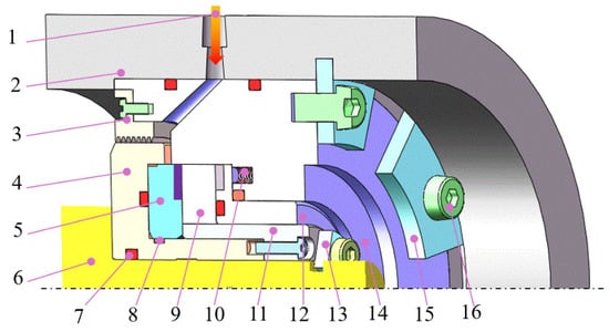
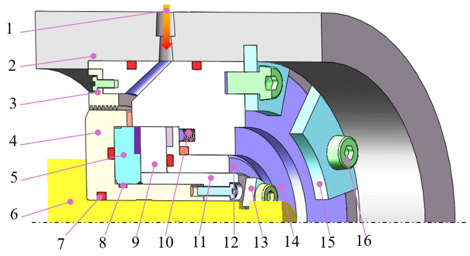
The core components of a dry gas seal (DGS) assembly include the seal seat, pusher ring, springs, gland, gaskets, and the seal ring, as illustrated in Figure 1. During assembly, the rotating ring is secured to the shaft via a shaft sleeve and rotates with it, while the stationary ring and springs are housed within the spring seat. Driven by the preload of the springs and guided by the stationary ring seat, the stationary ring is capable of axial floating compensation. Furthermore, O-rings and gaskets form a secondary sealing system to ensure the overall sealing integrity. The primary sealing interface consists of the rotating ring, the stationary ring, and the gas film between them [50]. The rotating ring is typically fabricated from a hard, rigid material with high strength, high toughness, or corrosion resistance, whereas the stationary ring is usually made of a compliant material to achieve optimal tribological properties and wear resistance. The operating mechanism relies primarily on the hydrodynamic effect. As the rotating ring spins at high speed, the buffer gas is drawn into the hydrodynamic grooves and flows along the channels. When the gas reaches the sealing dam, it encounters flow restriction and is compressed, thereby generating significant hydrodynamic pressure. Once this opening force overcomes the closing forces exerted by the spring preload and the medium’s static pressure, the stationary ring is pushed away. This creates a stable gas film, typically a few micrometers thick, between the mating faces. Maintained by axial dynamic force balance, this gas film enables the seal to operate reliably in a non-contact, low-wear manner [51].
Figure 1.
Schematic diagram of axial force on the sealing ring; 1—buffer gas; 2—sealing house; 3—labyrinth seal; 4—shaft sleeve; 5—rotating ring; 6—rotating shaft; 7—O-ring; 8—gasket; 9—stationary ring; 10—spring; 11—pressing sleeve; 12—thrust collar; 13—inner split retaining ring; 14—spring seat; 15—outer split retaining ring; 16—fixing bolt;.
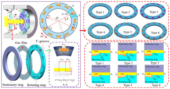
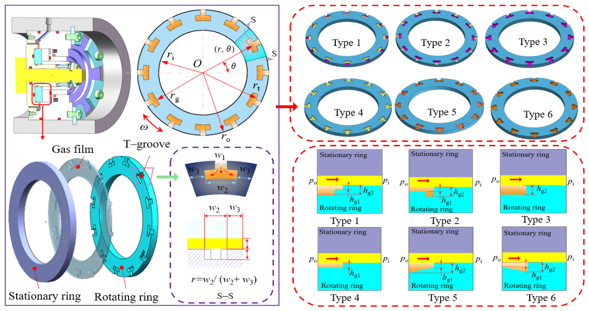
This study investigates the stepwise evolution patterns of six T-grooves with varying depths and analyzes the impact of the hydrodynamic effect on sealing performance. Figure 2 illustrates the end-face structural schematics of these six different T-groove configurations.
Figure 2.
Geometric model of the deep and shallow T–grooves.
2.2. Establishment of the Governing Equations
When establishing the governing equations for hydrodynamic lubrication, the following basic assumptions are proposed to simplify the analysis and ensure the feasibility of the mathematical model [52]:
- (a)
- The body forces and inertial forces during the gas flow process are neglected;
- (b)
- The gas flow is assumed to be an isothermal process, meaning the temperature remains constant, which ensures that the fluid viscosity remains unchanged throughout the flow;
- (c)
- The gas is treated as an ideal gas, and its flow is assumed to be laminar;
- (d)
- The sealing end faces are considered perfectly smooth, neglecting the effects of surface roughness on gas flow and lubrication performance.
Reynolds Equation
Considering that the end-face structure of the bidirectional T-groove dry gas seal is annular and the two mating faces are not in contact, with a gas film present in the sealing gap, the Cartesian coordinate system is transformed into a cylindrical coordinate system. The simplified mass-conserving compressible Reynolds equation is expressed as [8,53,54]:
The dimensionless form is expressed as follows:
where R is the non-dimensional radius; P is the non-dimensional gas film pressure; H is the non-dimensional gas film thickness; Λ is the compressibility parameter of the medium; and ω is the angular velocity of the shaft, rad/s.
The discretization of the Reynolds equation aims to transform the continuous partial differential equation into discrete algebraic equations, facilitating numerical solutions. These equations describe the pressure distribution and flow characteristics at each grid node.
By substituting the finite difference form into the Reynolds equation, the discretized form is obtained as follows:
The calculation coefficients in Formula (5) are as follows:
The gas film thickness equation is
where h0 is the reference gas film thickness, μm; hg is the groove depth of the T-groove, μm; and A represents the grooved region.
2.3. Numerical Method and Boundary Conditions
2.3.1. Regional Mesh Division
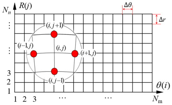
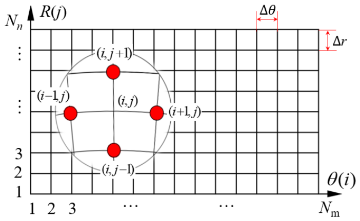
Figure 3 illustrates the meshing schematic using the central difference scheme. In the end-face structure of the deep and shallow T-grooves, the gas film thickness exhibits discontinuity in the film thickness equation. In the figure, p(i, j) denotes the gas film pressure at an arbitrary position on the end face. Since the sealing end face investigated in this study is annular, a polar coordinate system is employed for the analysis. The circumferential direction is divided into Nn grids, and the radial direction is divided into Nm grids. Each grid node corresponds to a non-dimensional gas film pressure P, which is described by the angular coordinate θ and the non-dimensional radius R in the polar coordinate system. This representation reflects the distribution characteristics of the gas film pressure P at each node, thereby illustrating the pressure variation across the end face of the seal ring [8,10,55,56].
Figure 3.
Regional mesh division.
2.3.2. Boundary Conditions
The T-grooves are periodically distributed along the circumferential direction of the sealing ring. Therefore, a single periodic unit can be used for the calculation. The pressure boundary conditions are:
The periodic pressure and temperature conditions are:
where Ng is the number of T-grooves; r is the radius at any end face of the sealing ring, mm; and θ is the development angle, rad.
2.3.3. Iterative Calculation
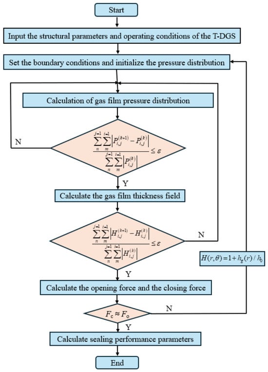
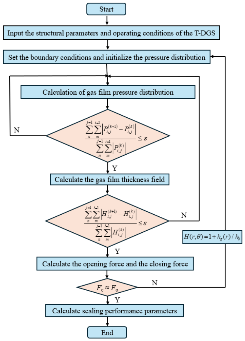
The Successive Over-Relaxation (SOR) algorithm is employed to solve the discretized equations, with the iterative scheme expressed in Equation (10). Following each iteration, the pressure field is updated, and the residuals are monitored to ensure convergence. In this equation, denotes the relaxation factor, which typically ranges from 1.0 to 1.5. To determine the termination of the iterative process, a relative error tolerance is adopted as the convergence criterion. This parameter plays a critical role in balancing computational accuracy and efficiency.
where error 1 is the convergence criterion for pressure and error 2 is the convergence criterion for film thickness.
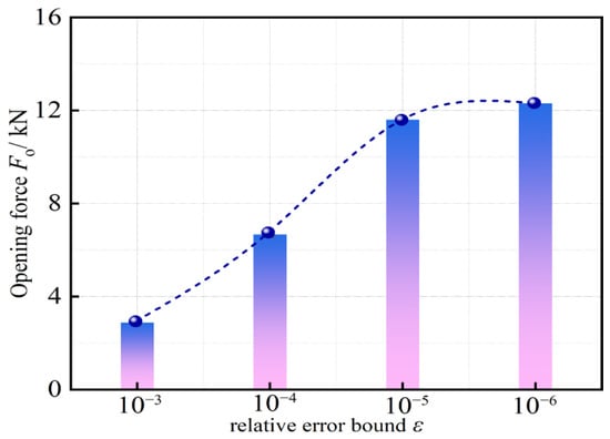
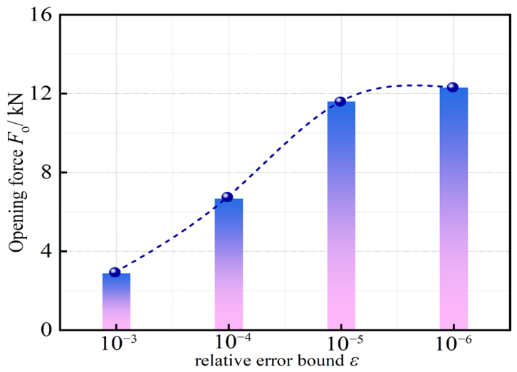
Figure 4 illustrates the effect of varying the relative error tolerance on sealing performance. As the relative error tolerance increases, the numerical uncertainty also increases, which leads to a higher gas film pressure required to generate the necessary opening force. When the relative error tolerance reaches 10−5 or 10−6, the gas film pressure tends to stabilize; its variation becomes negligible, indicating that the solution has converged [57,58,59].
Figure 4.
Effect of the relative error limit on sealing performance.
The numerical solution procedure for the T-groove dry gas seal (T–DGS) is illustrated in the computational flowchart shown in Figure 5. The entire numerical solution process is implemented through software programming.
Figure 5.
Numerical calculation process.
2.4. Calculation of Sealing Performance Parameters
By coupling the governing equations and boundary conditions, the gas film pressure distribution across the sealing end face is obtained. The steady-state performance parameters are calculated as follows:
- (1)
- Opening Force
The opening force refers to the external force required to overcome the friction and other resistances between the mating faces, thereby initiating the separation of the sealing end faces. The magnitude of the opening force depends on the design of the seal and its operating conditions.
- (2)
- Leakage
The gas mass leakage rate refers to the mass of gas leaking through the mating faces of the seal per unit time.
- (3)
- Gas Film Stiffness
The gas film stiffness refers to the ability of the gas film to resist deformation caused by external forces or pressure variations.
- (4)
- Stiffness-to-Leakage Ratio
The stiffness-to-leakage ratio refers to the proportional relationship between the gas film stiffness and the leakage rate, which reflects the overall performance of the sealing system.
3. Model and Mesh Verification
Table 1 lists the initial calculation parameters, and Table 2 presents the geometric parameters of the T-groove types.
Table 1.
Calculation parameters of the dry gas seal.
Table 2.
T-groove types.
3.1. Mesh Independence Verification
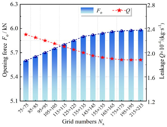
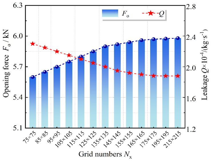
Figure 6 illustrates the grid independence test of the numerical model. Based on the results, the Type 4 grid configuration (195 × 195) was selected. At a resolution of 155 × 155, significant variations were observed in the force and leakage, indicating that the calculation accuracy was insufficient for practical applications. However, as the grid density increased to 195 × 195, the discrepancies in performance parameters diminished significantly. This suggests that a finer grid effectively enhances calculation accuracy, yielding more stable and reliable results. Consequently, the 195 × 195 grid was adopted in this study, as it achieves an optimal balance between computational accuracy and efficiency.
Figure 6.
Verification of mesh independence.
3.2. Validation of the Model
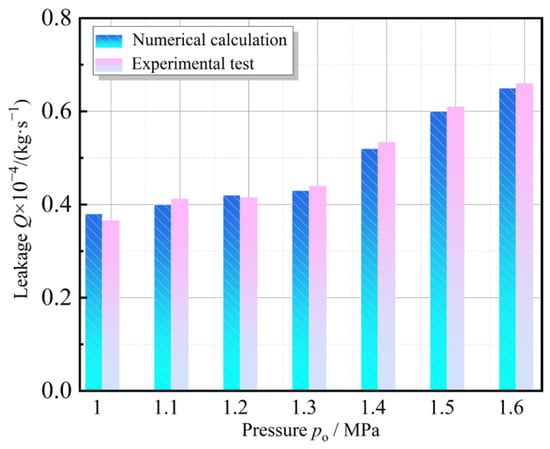
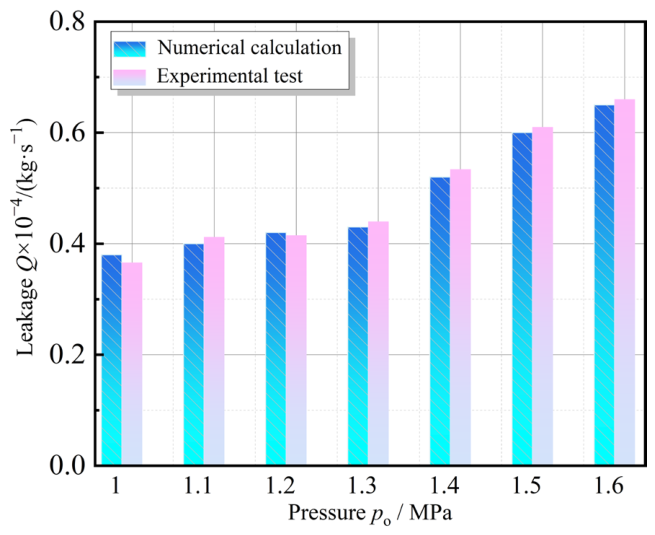
Figure 7 illustrates the validation process of the numerical model. The calculation program for the T-groove dry gas seal, using the geometric parameters listed in Table 1, was systematically validated. Specifically, the computational model designated as Type 4 was selected, with its operating parameters detailed in Table 2. The results indicated that the leakage rate increased significantly with the medium pressure. This was primarily due to the increased pressure differential across the sealing clearance, which led to a notable rise in gas leakage volume. Moreover, as the pressure increased, variations in gas density and dynamic viscosity further influenced the flow characteristics and leakage behavior. Compared with the experimental data, the numerical model accurately predicted the leakage behavior under various pressure conditions, confirming the validity and reliability of the calculation program. The relative error between the numerical and experimental values remained within a reasonable range (maximum relative error: 3.81%), thereby validating the numerical results.
Figure 7.
Validation of the computational model [10].
4. Results and Discussion
4.1. Gas Film Thickness Distribution
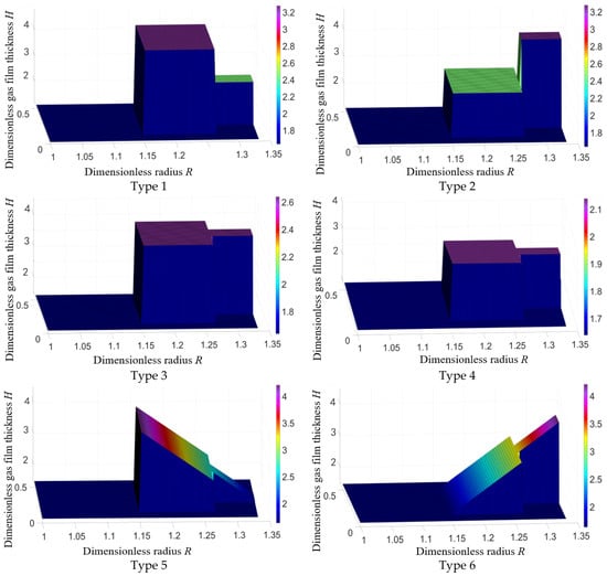
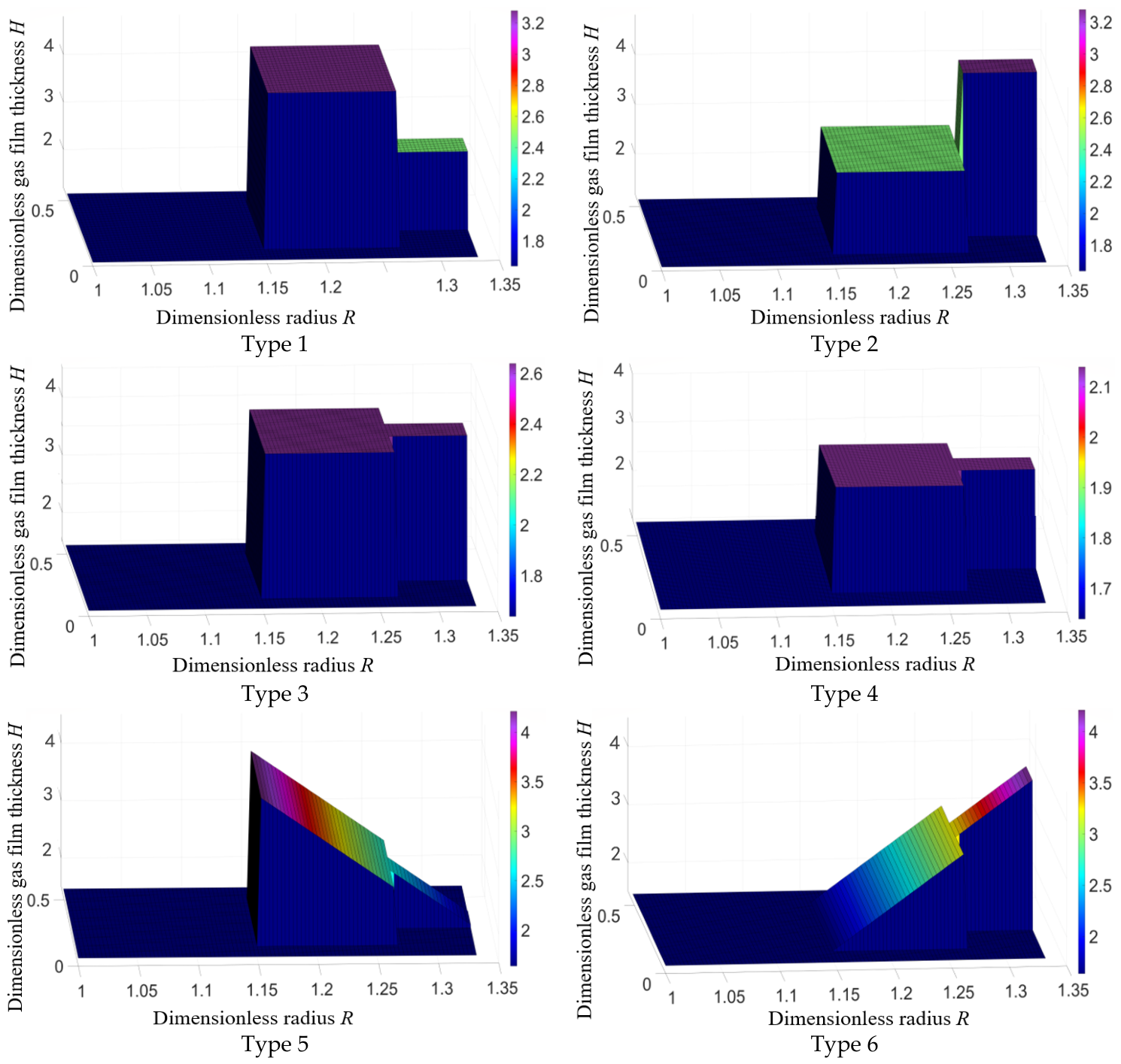
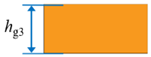
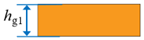
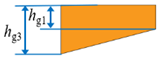
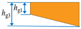
Figure 8 illustrates the distribution of the gas film thickness. Six computational models featuring T-grooves with varying depths were established to investigate the distribution characteristics of the dimensionless gas film thickness over a single periodic cycle. The results indicate that the groove profile directly dictates the distribution pattern of the gas film thickness. Specifically, Type 1 and Type 2 adopt an alternating deep- and shallow-groove structure, which induces significant step changes in the local gas film thickness. Type 3 features a fully deep-groove design, yielding a thicker and more uniform gas film. This configuration is beneficial for enhancing sealing performance but may increase flow resistance. Conversely, Type 4 utilizes a fully shallow-groove design, resulting in a thinner and more uniform gas film with lower flow losses, making it suitable for operating conditions with less stringent film thickness requirements. Furthermore, Type 5 and Type 6 incorporate a gradient design concept to achieve continuous variations in groove depth. Type 5 exhibits a smooth transition from deep to shallow grooves, whereas Type 6 demonstrates a gradual progression from shallow to deep grooves. This continuously varying thickness distribution facilitates the adjustment of gas film characteristics while effectively balancing sealing effectiveness and flow losses.
Figure 8.
Distribution of gas film thickness in deep and shallow grooves.
Overall, the groove profile is the key factor determining the distribution characteristics of the gas film thickness. By rationally designing the groove depth distribution, an effective trade-off between sealing performance and flow loss can be achieved. Specifically, the full deep-groove design (Type 3) is suitable for operating conditions with high sealing performance requirements, while the full shallow-groove design (Type 4) is applicable to low-flow-resistance scenarios. Meanwhile, the gradient groove depth designs (Types 5 and 6) achieve a continuously varying film thickness distribution, offering a new design concept for the synergistic optimization of sealing effectiveness and flow loss.
4.2. Gas Film Pressure Distribution
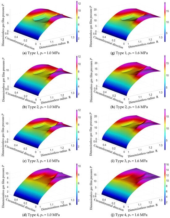
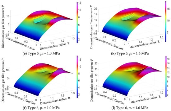
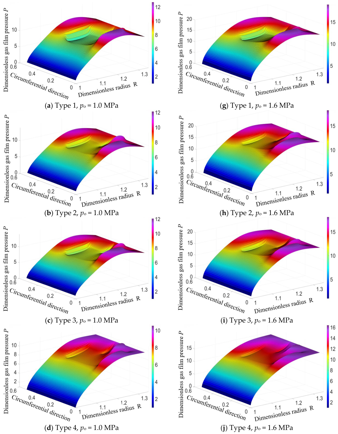
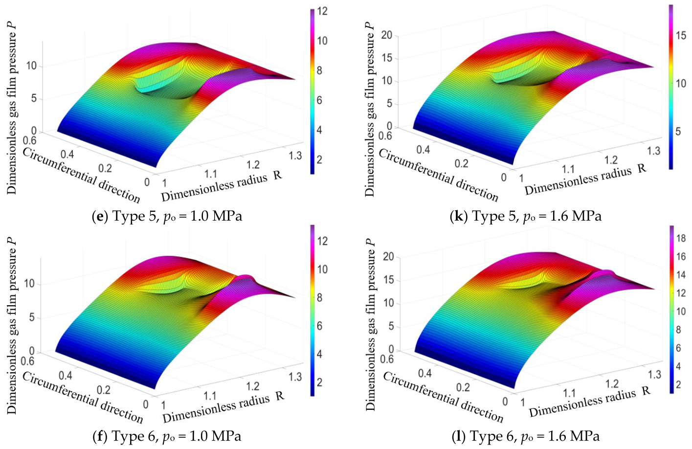
Figure 9 illustrates the gas film pressure distribution under varying operating pressures. Figure 9a–f depict the pressure distribution at a rotational speed of 14 krpm and a supply pressure of 1.0 MPa. Under these identical conditions, the gas film pressure in Type 4 is relatively low, while the film pressures in the other models remain largely consistent. As the supply pressure increases to 1.6 MPa, the pressure distribution undergoes significant changes, as shown in Figure 9g–l. The elevated supply pressure increases gas density and kinetic energy, significantly enhancing the supporting capacity of the gas film and resulting in an overall upward trend in the pressure distribution. Among the models, Type 6 exhibits the most substantial pressure increase, followed by Type 4, indicating that the Type 6 model provides superior gas film support under high-pressure conditions, thereby effectively improving the sealing performance. Furthermore, the supply pressure regulates the state of the gas film by altering its stiffness and flow-field characteristics. Under low-pressure conditions, the gas film stiffness is weak and insufficient to balance the internal pressure distribution; significant local pressure differentials can easily induce gas film instability and seal failure. As the supply pressure rises, the enhanced gas stiffness reinforces the seal clearance, promoting a more uniform pressure distribution. However, excessively high supply pressure can exacerbate the nonlinear characteristics of gas flow, thereby increasing the risk of dynamic instability in the gas film.
Figure 9.
Gas film pressure distribution at different pressures.
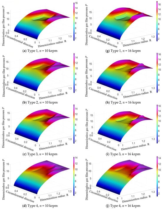
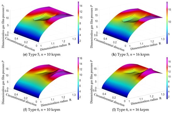
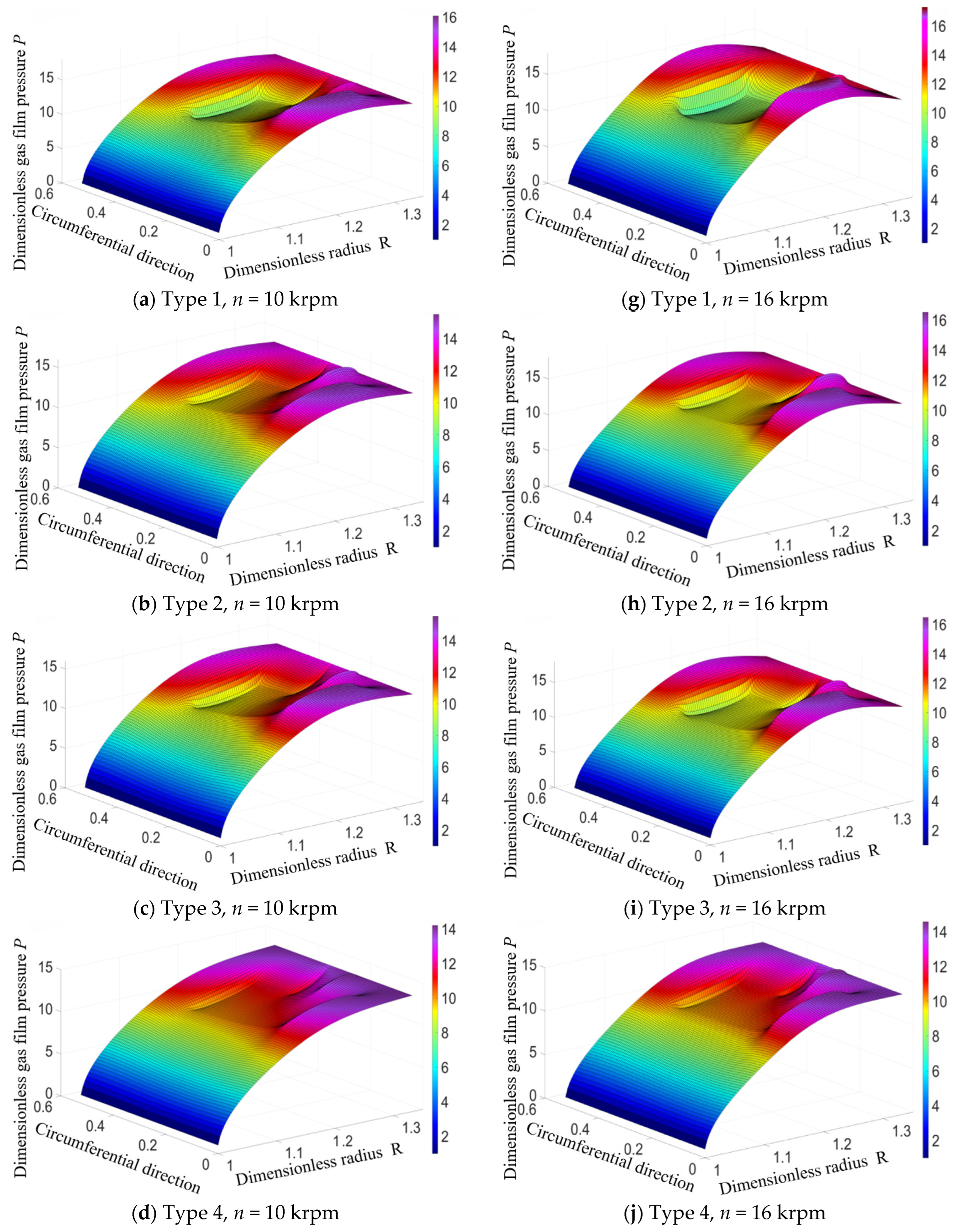
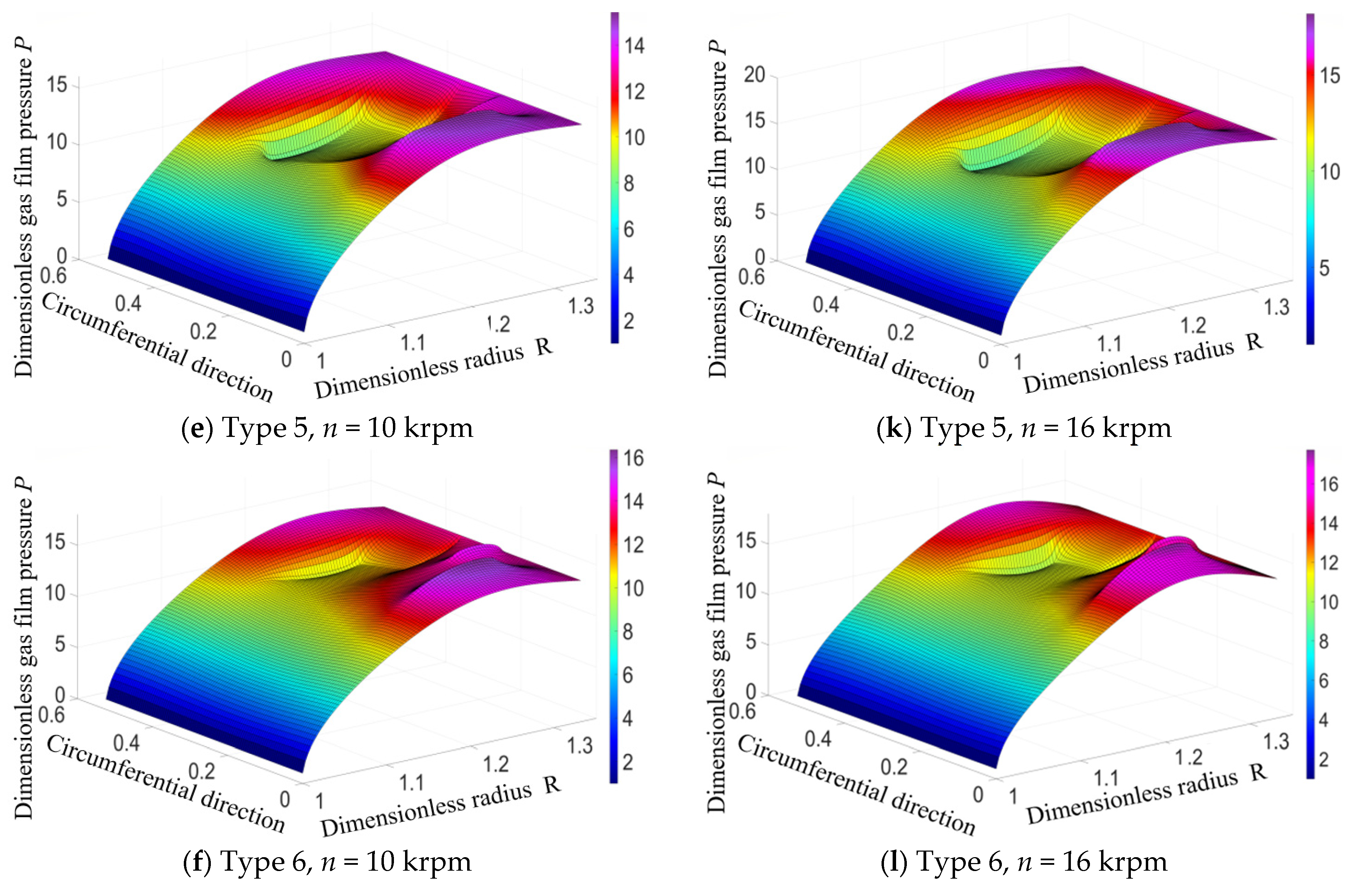
Figure 10 illustrates the gas film pressure distribution under varying rotational speeds. Figure 10a–f depict the pressure profiles at a medium pressure of 1.4 MPa and a rotational speed of 10 krpm. Under these conditions, the gas film pressures in Type 6 are relatively high, whereas those in Type 2, Type 3, and Type 5 exhibit minimal variation. In contrast, Type 4 demonstrates the lowest gas film pressure. When the rotational speed increases to 16 krpm, the gas film pressure distribution undergoes significant changes, as shown in Figure 10g–l. The elevated gas flow velocity enhances the dynamic pressure within the gas film. The hydrodynamic effect within the T-grooves effectively supports the gas film, thereby elevating the overall film pressure. Among the different groove configurations, the pressure increase in Type 2 and Type 3 is the most pronounced. The gas film pressure exhibits a curved decline along the flow direction, accompanied by a significant pressure drop at the interface between the T-groove and the sealing dam. At low rotational speeds, the overall pressure remains relatively low due to the weak hydrodynamic effect resulting from insufficient gas flow velocity and inadequate gas film support. However, as the rotational speed increases, the kinetic energy of the gas rises significantly. The enhanced hydrodynamic effect causes the pressure distribution within the T-groove region to become irregular. Concurrently, intensified centrifugal forces exacerbate the uneven radial distribution of the gas. This strong coupling effect between hydrodynamic pressure and centrifugal force at high rotational speeds significantly increases the radial pressure gradient within the gas film, potentially inducing gas film instability or even rupture, thereby escalating the risk of seal leakage.
Figure 10.
Gas film pressure distribution at different rotational speeds.
4.3. Effect of Operating Conditions on Sealing Performance
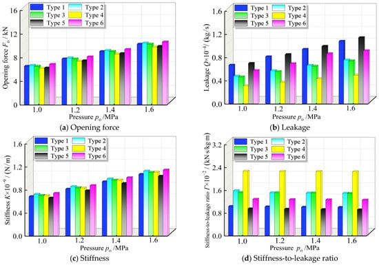
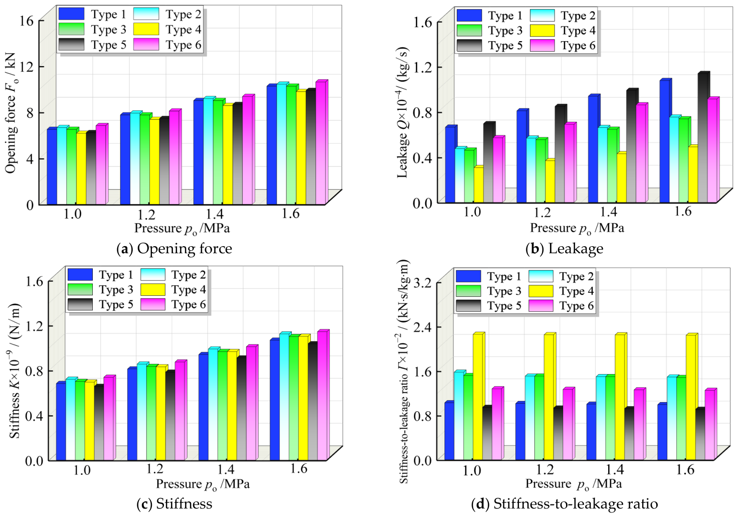
Figure 11 illustrates the effect of pressure variations on the performance of dry gas seals. As depicted in Figure 11a,c, an increase in pressure significantly enhances the hydrodynamic effect within the seal clearance, thereby improving both the opening force and the gas film stiffness. Conversely, Figure 11b indicates that the leakage rate rises substantially with increasing pressure. This is attributed to the enlarged pressure differential across the seal clearance, which accelerates the gas flow velocity and consequently increases the volume of gas leaking through the clearance. A comparison of the six different T-groove models reveals that Type 1 and Type 5, in particular, exhibit significant variations in leakage rate in response to pressure changes, indicating a high sensitivity to pressure fluctuations. Furthermore, Figure 11d presents the dynamic trend of the stiffness-to-leakage ratio across varying medium pressures. While the enhancement of gas film stiffness typically influences this ratio, it remains relatively stable within certain pressure ranges, suggesting an equilibrium between gas film stiffness and leakage rate. Based on the comparative analysis, the stiffness-to-leakage ratios are ranked in descending order as follows: Type 4 > Type 3 > Type 2 > Type 6 > Type 1 > Type 5. This ranking demonstrates that Type 4 can effectively control leakage while maintaining high gas film stiffness, providing a crucial basis for the optimal design of high-performance seal grooves.
Figure 11.
Effect of pressure variations on sealing performance (n = 14 krpm, po = 1.0~1.6 MPa).
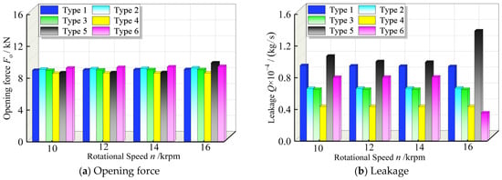
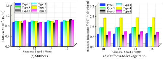
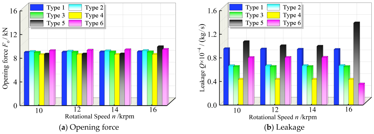
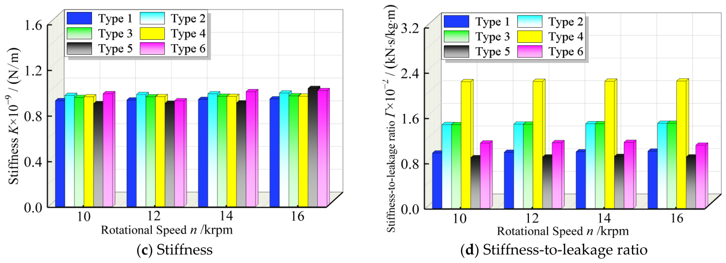
Figure 12 illustrates the effect of rotational speed on the performance of dry gas seals. As depicted in Figure 12a,c, both the opening force and gas film stiffness exhibit a gradual upward trend with increasing rotational speed. Notably, the Type 5 model demonstrates outstanding performance at higher speeds, primarily driven by the significant enhancement in the kinetic energy of the gas flow. This elevated kinetic energy bolsters the load-carrying capacity of the gas film, thereby further improving the sealing performance. However, this increased kinetic energy also accelerates the gas flow velocity within the T-grooves, resulting in a higher leakage rate. A comparison of the leakage rates among the six groove models, presented in Figure 12b, reveals that Type 5 exhibits the highest leakage rate, whereas Type 4 maintains the lowest. Furthermore, Figure 12d indicates that although the leakage rate increases alongside the enhanced gas film stiffness, the stiffness-to-leakage ratio remains relatively stable within a certain range. This suggests that the improvement in gas film stiffness can, to some extent, mitigate the adverse effect of the rising leakage rate induced by higher rotational speeds. Based on the comparative analysis, the stiffness-to-leakage ratios are ranked in descending order as follows: Type 4 > Type 3 > Type 2 > Type 6 > Type 1 > Type 5. This ranking reflects the balance between gas film stiffness and leakage rate across different T-groove structures, highlighting the variations in sealing performance among the groove types for practical applications.
Figure 12.
Effect of rotational speed on seal performance (po = 1.4 MPa n = 10~16 krpm).
5. Conclusions
- (1)
- A theoretical model for bidirectional T-groove dry gas seals was established. Based on gas film lubrication theory, the hydrodynamic lubrication governing equations were formulated, and a compressible gas film thickness equation characterizing the step evolution of T-grooves was proposed. This provides a solid foundation for the numerical calculation of seal performance under complex operating conditions.
- (2)
- The competitive mechanism of pressure variations on seal performance was revealed. As pressure increases, the enhanced hydrodynamic effect significantly improves both the opening force and gas film stiffness, but leads to an increased leakage rate. Different groove types exhibit varying sensitivities to pressure. In terms of the comprehensive stiffness-to-leakage ratio, the performance ranking is: Type 4 > Type 3 > Type 2 > Type 6 > Type 1 > Type 5.
- (3)
- The influence of rotational speed on gas film dynamic characteristics was elucidated. Although higher rotational speeds enhance gas kinetic energy, thereby improving load-carrying capacity and seal performance, they also accelerate gas flow within the grooves, resulting in increased leakage. Specifically, the Type 5 model shows a significant improvement in load-carrying capacity but suffers from higher leakage, whereas Type 4 demonstrates optimal performance in leakage control.
- (4)
- The optimal groove structure was identified. By comparing the stiffness-to-leakage ratios of six models, it was found that Type 4 and Type 3 structures achieve the best balance between gas film stiffness and leakage control. This confirms the critical role of specific groove depths and step designs in enhancing the comprehensive seal performance under deep-sea operating conditions.
The optimized groove configurations of Type 4 and Type 3 proposed in this study provide a theoretical basis for the selection and design of dry gas seals in rotating equipment such as centrifugal compressors and expanders, which are prone to frequent start–stop cycles or reversal risks, in the petrochemical and natural gas transmission industries. This contributes to reducing the risk of medium leakage. Future research can further investigate the performance evolution of seals under ultra-high pressure, cryogenic temperature, and liquid-containing media by incorporating fluid–structure interaction effects. Additionally, multi-objective parameter optimization, experimental validation, and customized groove designs for special scenarios, such as hydrogen energy storage and transportation, should be explored to promote the development of dry gas seal technology toward higher reliability, lower leakage, and longer service life.
Author Contributions
Conceptualization, H.M. and J.C.; methodology, Z.C. and J.R.; formal analysis, L.Z.; investigation, S.Y. and H.M.; resources, L.Z.; data curation, J.R.; writing—original draft preparation, L.Z.; visualization, L.Z.; supervision, H.M. and J.C.; project administration, L.Z. writing—review and editing, S.Y. and H.M.; validation, Z.C. and L.Z. All authors have read and agreed to the published version of the manuscript.
Funding
This work is supported by Project of the Education and Science Innovation of Gansu Province (NO. 2026B-217).
Data Availability Statement
All data generated or analyzed during this study are included in this published article.
Acknowledgments
The authors are grateful to the reviews for their careful and detailed comments.
Conflicts of Interest
Author Hongjun Ma was employed by the National Pipeline Network Group Western Pipeline Company. Authors Jinyun Cao, and Zhanyang Chen was employed by the Lanpec Technologies Limited. The remaining authors declare that the research was conducted in the absence of any commercial or financial relationships that could be construed as a potential conflict of interest.
Nomenclature
| Symbol Latin symbols | Meaning |
| error1 | The convergence criterion for pressure |
| error2 | The convergence criterion for film thickness |
| Fc | Closing force, kN |
| Fo | Opening force, kN |
| H | The dimensionless gas film thickness |
| h | The gas film thickness at any position of the sealing clearance, μm |
| h0 | The film thickness, μm |
| hg | The gas film thickness in the T-groove, μm |
| hg1 | Groove depth 1, μm |
| hg2 | Groove depth 2, μm |
| hg3 | Groove depth 3, μm |
| K | Gas film stiffness, N/m |
| Ng | Numbers of T-grooves |
| Nm | Circular direction grid number |
| Nn | Radial direction grid number |
| Nx | Grid numbers |
| n | Rotational speed, krpm |
| P | The dimensionless gas film pressure |
| p | Pressure, MPa |
| pi | Sealing ring outlet pressure, MPa |
| po | Sealing ring inlet pressure, MPa |
| Q | Leakage, kg/s |
| R | The dimensionless radius |
| r | The radius at any end face of the sealing ring, mm |
| rg | Radius at the root, mm |
| ri | Inner radius of moving ring, mm |
| ro | Outer radius of moving ring, mm |
| rt | Middle radius of T-groove, mm |
| SOR | Successive Over-Relaxation |
| The circumferential average velocity, m/s | |
| ur | Radial velocity, m/s |
| The radial average velocity, m/s | |
| w1 | Circumferential arc length of the gas supply groove, mm |
| w2 | Circumferential arc length of the T-groove, mm |
| w3 | Circumferential arc length of the inter-groove ungrooved region, mm |
| ρ | Fluid density, kg·m−3 |
| ω | Angular velocity of rotation, rad/s |
| ε | Relative error bound |
| θ | Development angle, rad |
| Λ | The compressibility coefficient of the medium |
| μ | Gas viscosity, Pa·s |
| Γ | Stiffness-to-leakage ratio, kN∙s/kg∙m |
| Ω | T-groove region |
| Δθ | θ-direction dimensionless difference step length |
| Δr | r-direction dimensionless difference step length |
| dθ | The minor component of Angle theta |
| dz | The z component |
References
- Bai, S.; Yang, D.; Yang, J. Salinity effect in seawater thermoelastohydrodynamic lubrication of double spiral groove face seals. Materials 2026, 19, 285. [Google Scholar] [CrossRef] [Scilit] [PubMed]
- Hu, L.; Li, W.; Li, B.; Cui, B.; Wang, Z.; Wang, Y. Wear characteristics and mechanism evaluation of high–speed petal magnetic rotor series bearings (HPMRSBs) in vacuum. Compos. Part B Eng. 2026, 313, 113369. [Google Scholar] [CrossRef] [Scilit]
- Hu, L.; Ye, J.; Cui, B.; Wang, Z.; Wang, Y. Prediction and evaluation of the influence of static-dynamic aging wear of grease on life of high performance bearings (HPBs). Eng. Fail. Anal. 2025, 179, 109829. [Google Scholar] [CrossRef] [Scilit]
- Zhang, C.; Jiang, J.; Zhao, W.; Jin, J.; Peng, X. A comprehensive multi-objective, multi-parameter and multi–condition optimization of a spiral groove in dry gas seals. J. Braz. Soc. Mech. Sci. 2022, 44, 206. [Google Scholar] [CrossRef] [Scilit]
- Chen, Y.; Peng, X.; Jiang, J.; Meng, X.; Li, J. Experimental and theoretical studies of the dynamic behavior of a spiral–groove dry gas seal at high-speeds. Tribol. Int. 2018, 125, 17–26. [Google Scholar] [CrossRef] [Scilit]
- Chen, Y.; Wang, Q.; Peng, X.; Li, Y.; Wang, B.; Jin, J. Flow field and sealing performance analysis of compliant foil face gas seal. Adv. Mech. Eng. 2022, 14, 16878132221108488. [Google Scholar] [CrossRef] [Scilit]
- Hu, L.; Pueh, L.H.; Wang, Z.; Wang, Y. Surface performance control and evaluation of precision bearing raceway with wireless sensing CBN grinding wheel. Wear 2025, 568, 205966. [Google Scholar] [CrossRef] [Scilit]
- Ren, H.; Miao, Z.; Feng, X.; Labidi, A.; Zhao, Y.; Wang, C. Modulating the built-in electric field of S–scheme heterojunction via oxygen vacancies for boosting photocatalytic ciprofloxacin degradation. Chin. Chem. Lett. 2026, 112557. [Google Scholar] [CrossRef] [Scilit]
- Chen, L.; Li, S.; Zhu, S. Physicochemical coevolution of SUS304 ultra-thin steel foils induced by laser and its effect on interface bonding of steel/CFRP joints. J. Iron Steel Res. Int. 2026, 32, 80. [Google Scholar] [CrossRef] [Scilit]
- Liu, M.; Tian, J.; Zhao, J.; Sun, Y.; Liang, J.; Zheng, Y.; Zhang, W.; Wu, X.; Yuan, J.; Fu, H. Seismic performance of CFRP-strengthened steel fiber reinforced concrete composite columns: Experimental, numerical and theoretical analyses. Constr. Build. Mater. 2025, 505, 144692. [Google Scholar] [CrossRef] [Scilit]
- Hu, L.; Pueh, L.H.; Wang, D.; Wang, Z. Fatigue failure of high precision spindle bearing under extreme service conditions. Eng. Fail. Anal. 2024, 158, 107951. [Google Scholar] [CrossRef] [Scilit]
- Liu, X.; Guan, X.; Zhong, Y.; Xiao, Q.; Cao, Y.; Zhang, W.; Zhang, S.; Zheng, Y.; Ga, M.; Chen, D.; et al. Effect of different gaps in the conductor rail joints on the current-carrying wear performance of carbon skateboards/conductive rail contact. Wear 2024, 536–537, 205172. [Google Scholar] [CrossRef] [Scilit]
- Chen, L.; Wang, Y.; Li, Y.; Zhang, Z.; Xue, Z.; Ban, X.; Hu, C.; Li, H.; Tian, J.; Mu, W.; et al. Effect of nickel content and cooling rate on the microstructure of as cast 316 stainless steels. Crystals 2025, 15, 168. [Google Scholar] [CrossRef] [Scilit]
- Zhang, L.; Ding, X.; Wang, S.; Zhang, S. Flow characteristics and experimental verification of T-groove dry gas seal under different flow states. Lubricants 2024, 13, 9. [Google Scholar] [CrossRef] [Scilit]
- Zhang, L.; Ding, X.; Wang, S.; Zhang, S.; Ding, J. Research progress on the dynamic stability of dry gas seals. Processes 2024, 12, 575. [Google Scholar] [CrossRef] [Scilit]
- Ding, J.; Miao, Y.; Yu, S.; Wang, S.; Ding, X. Exploring the sealing properties of thermodynamic lubrication in ultra-high-speed dry gas seals considering heat transfer modeling. J. Mech. Sci. Technol. 2026, 40, 385–399. [Google Scholar] [CrossRef] [Scilit]
- Wang, S.; Zhang, M.; Ding, X.; Wang, Z.; Wang, Y. Influence of slip effects and flow regimes on the sealing performance of diamond cross-section groove dry gas seals. Ind. Lubr. Tribol. 2026, 1–20. [Google Scholar] [CrossRef] [Scilit]
- Wang, Y.; Ge, Y.; Huang, G.; Hu, Q.; Hu, P. Microscale flow field analysis and flow prediction model exploration of dry gas seal. IEEE Access 2020, 8, 52663–52675. [Google Scholar] [CrossRef] [Scilit]
- Fairuz, Z.M.; Jahn, I. The influence of real gas effects on the performance of supercritical CO2 dry gas seals. Tribol. Int. 2016, 102, 333–347. [Google Scholar] [CrossRef] [Scilit]
- Jamshidi, N.; Ebrahimi, M.R. Effect of geometric parameters on the performance of dry gas seal with trapezoidal grooves. Chall. Nano Micro Scale Sci. Technol. 2021, 9, 126–134. [Google Scholar]
- Park, Y.; Hahn, M.; Jang, G. Effect of laminar, turbulent and slip conditions on the dynamic coefficients of a dry gas seal. Lubricants 2023, 11, 98. [Google Scholar] [CrossRef] [Scilit]
- Yang, P.; Deng, Q.; Xu, H.; Ma, W.; Sun, X. Dynamic tracking characteristic of high-speed dry gas seal considering centrifugal inertia effect and its interaction with complex special flow phenomena. Ind. Lubr. Tribol. 2026, 78, 823–832. [Google Scholar] [CrossRef] [Scilit]
- Sun, X.; Song, P.; Mao, W.; Deng, Q.; Xu, H.; Chen, W. Dynamic contact analysis of dry gas seal during start-stop process considering material properties and surface topography of seal rings. CIESC J. 2021, 72, 4279–4291. [Google Scholar]
- Lai, H.; Pengyang, J.; Zixi, W.; Yuming, W. Study on type of magnetic suspension rotor groove and wear of drop touchdown bearing. Eng. Appl. Comput. Fluid Mech. 2024, 18, 2422065. [Google Scholar] [CrossRef] [Scilit]
- Teng, L.; Jiang, J.; Peng, X.; Li, J. Influence of surface grooving methods on steady and dynamic performance of spiral groove gas face seals. Alex. Eng. J. 2023, 64, 55–80. [Google Scholar] [CrossRef] [Scilit]
- Yan, R.; Chen, H.; Zhang, W.; Hong, X.; Bao, X.; Ding, X. Calculation and verification of flow field in supercritical carbon dioxide dry gas seal based on turbulent adiabatic flow model. Tribol. Int. 2022, 165, 107275. [Google Scholar] [CrossRef] [Scilit]
- Yan, R.; Chai, B.; Ma, L.; Chen, H.; Ding, X. Dynamic coefficient investigation for supercritical carbon dioxide dry gas seal based on complete variable perturbation model. Lubricants 2024, 12, 298. [Google Scholar] [CrossRef] [Scilit]
- Hahn, M.; Park, Y.; Kang, M.; Jun, S.; Jang, G. Effects of laminar, turbulent, and slip conditions in a fluid film on a dry gas seal. Machines 2022, 10, 954. [Google Scholar] [CrossRef] [Scilit]
- Brunetiere, N.L. A modified turbulence model for low Reynolds numbers: Application to hydrostatic seals. Tribology 2005, 127, 130–140. [Google Scholar] [CrossRef] [Scilit]
- Wang, B.; Zhang, H.; Cao, H. Flow dynamics of a spiral-groove dry-gas seal. Chin. J. Mech. Eng. 2013, 26, 78–84. [Google Scholar] [CrossRef] [Scilit]
- Xu, H.; Deng, Q.; Sun, X.; Ma, W. Dynamic stability of dry gas seal under gas film adaptive-adjustment. Int. J. Mech. Sci. 2026, 327, 111979. [Google Scholar] [CrossRef] [Scilit]
- Cui, B.; Ding, X.; Wang, S.; Zhang, L.; Cheng, B.; Wu, B.; Wang, B. Numerical simulation of fishtail biomimetic groove for dry gas seals. J. Process. 2024, 12, 1494. [Google Scholar] [CrossRef] [Scilit]
- Zheng, W.; Sun, J.; Ma, C. Comprehensive performance of diffused self–pumping hydrodynamic mechanical seal. Tribology 2024, 44, 86–695. [Google Scholar]
- He, T.; Zhang, Q.; Yan, Y.; Dong, J.; Zhou, P. Numerical simulation of a new designed mechanical seals with spiral groove structures. Lubricants 2023, 11, 70. [Google Scholar] [CrossRef] [Scilit]
- Hu, L.; Li, B.; Wang, Z.; Wang, Y. Analysis and evaluation of multi-state wear mechanism of elastic-flexible thin-walled bearings. Tribol. Int. 2025, 202, 110293. [Google Scholar] [CrossRef] [Scilit]
- Lu, J. Theoretical analysis and experiment on gas film stiffness with slip flow in a spiral-grooved dry gas seal. Ind. Lubr. Tribol. 2021, 73, 1226–1236. [Google Scholar] [CrossRef] [Scilit]
- Badykov, R.R.; Falaleev, S.V. Advanced dynamic model development of dry gas seal. J. Procedia Eng. 2017, 176, 344–354. [Google Scholar] [CrossRef] [Scilit]
- Badykov, R.; Falaleev, S.; Yurtaev, A.; Luo, D.; Liu, Z.; Molokanov, A. A quasi-transient approach for determining fluid film dynamic properties in dry gas seals. Int. J. Heat Fluid Flow. 2026, 121, 110474. [Google Scholar] [CrossRef] [Scilit]
- Hu, F.; He, Q.; Yin, Y.; Huang, W. Wear monitoring of dry gas seals through seal face structure design. Tribol. Trans. 2025, 68, 768–783. [Google Scholar] [CrossRef] [Scilit]
- Ma, G.; Ding, X.; Ding, J.; Wang, S.; Wang, Y.; Jiang, A. A Thermal-Hydrodynamic Study of Lubrication and Sealing Performance in Dry Gas Seals with Potential Application to Supercritical Water Vapor Flow Fields. J. Supercrit. Fluids. 2026, 8, 107016. [Google Scholar]
- Jiang, A.; Ding, J.; Ding, X.; Wang, S.; Jiang, H.; Ling, N. Multi-physics coupling simulation and sealing performance optimization of supercritical CO2 stepped T-groove dry gas seals. J. Supercrit. Fluids 2025, 229, 106830. [Google Scholar] [CrossRef] [Scilit]
- Wang, L.; Sun, J. Performance analysis and bi-objective optimization study on diffuser self–pumping hydrodynamic mechanical seal. Tribology 2024, 44, 947–959. [Google Scholar]
- Ren, B.; Hao, M. Performance analysis and software development of spiral groove dry gas seal based on semi-analytical method. J. Chem. Pharm. Eng. 2019, 40, 55–59. [Google Scholar]
- Wang, Y.; Hao, Z.; Wu, J. Investigation on the dynamic characteristics for high-speed mechanical seal considering turbulent cavitating flow and inertia effect. Ind. Lubr. Tribol. 2024, 76, 864–872. [Google Scholar] [CrossRef] [Scilit]
- Lu, Q.; Jiang, J.; Meng, X.; Chen, Y.; Ma, Y.; Peng, X. Effect of the 3D layered flow channels within the rotating ring on the steady-state performance of dry gas seals. Tribol. Int. 2025, 208, 110651. [Google Scholar] [CrossRef] [Scilit]
- Wang, C.; Li, H.; Mei, A.; Jin, H.; Yang, N.; Xiao, G.; Zhang, R.; Tang, H. Experimental and Numerical Simulation Study on the Two–Phase Threshold Pressure Gradient of Fractured Wells in Tight Gas Reservoirs. Processes 2026, 14, 2292. [Google Scholar] [CrossRef] [Scilit]
- Ding, X.; Lu, J. Theoretical analysis and experiment on gas film temperature in a spiral groove dry gas seal under high speed and pressure. Int. J. Heat Mass Transf. 2016, 96, 438–450. [Google Scholar] [CrossRef] [Scilit]
- Ding, X.; Lu, J.; Zhang, W.; Zhai, X. Test analysis of gas film stiffness and system damping of spiral groove dry gas seal. In Proceedings of the 2016 13th International Conference on Ubiquitous Robots and Ambient Intelligence (URAI); IEEE: New York, NY, USA, 2016; pp. 279–287. [Google Scholar]
- Yang, H.; Xu, Y.; Liu, T.; Liu, T.; Huang, Z.; Xie, D. Research on ultra-clean micro gas flow calibration technology of passive piston type with sealing. Flow Meas. Instrum. 2024, 100, 102735. [Google Scholar] [CrossRef] [Scilit]
- Johansson, P.; Marklund, P.; Björling, M.; Shi, Y. Effect of roughness on the running-in behavior and tribofilm formation of carbon fiber reinforced PTFE composite in trace moisture environment. Wear 2022, 500, 204367. [Google Scholar] [CrossRef] [Scilit]
- Li, D.; Ye, J.; Chen, G.; Hu, L.; Wang, Z.; Qian, T.; Zhang, J.; Zi, M.; Liang, C. Performance Evaluation of a Halbach Permanent Magnet Axial Protection Bearing Under Vertical Magnetic Levitation Flywheel Rotor Drop. Lubricants 2026, 14, 40. [Google Scholar] [CrossRef] [Scilit]
- Yuan, T.; Yang, R.; Li, Z.; Yang, Q.; Song, L. Thermal characteristics and cooling effect for sco2 dry gas seal with multiple dynamic groove types. Appl. Therm. Eng. 2024, 236, 121896. [Google Scholar] [CrossRef] [Scilit]
- Hu, L.; Wang, Z.; Wang, J.; Wang, Y. Derivative analysis and evaluation of roll-slip fretting wear mechanism of ultra-thin-walled bearings under high service. Wear 2024, 562, 205630. [Google Scholar] [CrossRef] [Scilit]
- Xu, H.; Song, P.; Mao, W.; Deng, Q. The performance of spiral groove dry gas seal under choked flow condition considering the real gas effect. Proc. Ins. Mec. Eng. Part J. Eng. Tribol. 2020, 234, 554–566. [Google Scholar] [CrossRef] [Scilit]
- Yu, G.; Lai, H.; Yongli, Q. Fretting slip Wear mechanism of AlCrN coated cemented carbide tool on titanium alloy TC4 under ultimate continuous cutting. Int. J. Refract. Met. Hard Mater. 2026, 140, 107859. [Google Scholar] [CrossRef] [Scilit]
- Tian, J.; Li, G.; Wu, X.; Yu, W.; Zuo, Y.; Yuan, J.; Wang, W.W.; Fu, H.; Liu, M.; Wang, R. Self-sensing performance and theoretical model for the interface of self-sensing engineered cementitious composites and conductive concrete under shear loading. Case Stud. Constr. Mater. 2025, 23, e05618. [Google Scholar] [CrossRef] [Scilit]
- Yu, G.; Jia, L.; Lai, H.; Anbang, J.; Liping, W. Motion system modeling and acceleration analysis of five-axis hybrid machine tool. Adv. Eng. Inform. 2026, 71, 104368. [Google Scholar] [CrossRef] [Scilit]
- He, Y.; Wang, Y.; Huang, Z.; Kong, K.; Zhao, Q.; Jin, X.; Wang, Y.; Liu, W. Efficient preparation and evaluation of dry gas sealed spiral grooves. High Temp. Mater. Process. 2025, 44, 20240025. [Google Scholar] [CrossRef] [Scilit]
- Wang, Y.; Niu, S.; Zhang, J.; Feng, C.; Wang, Y.; Shen, D.; Li, D.; Li, T.; Cao, P.; Zhang, Y. Development status of dynamic sealing technology and discussion on advanced sealing technologies. Lubricants 2025, 13, 2075–4442. [Google Scholar] [CrossRef] [Scilit]

Disclaimer/Publisher’s Note: The statements, opinions and data contained in all publications are solely those of the individual author(s) and contributor(s) and not of MDPI and/or the editor(s). MDPI and/or the editor(s) disclaim responsibility for any injury to people or property resulting from any ideas, methods, instructions or products referred to in the content. |
© 2026 by the authors. Licensee MDPI, Basel, Switzerland. This article is an open access article distributed under the terms and conditions of the Creative Commons Attribution (CC BY) license.