


Abstract
Aiming at insufficient rated torque and excessive magnet thermal loss of vehicle high-power-density BLDC motors, a multi-objective optimization framework integrating a surrogate model and NSGA-II is proposed. An eight-pole 48-slot finite-element model is built to analyze initial electromagnetic defects. Taguchi experiments conduct parameter sensitivity screening to reduce simulation cost. Two surrogate models (RSM, BP neural network) are quantitatively compared via R2 and MSE; the BP network achieves R2 = 0.995 for magnet loss with overall error below 5%. Combined with NSGA-II, Pareto-optimal structural parameters are obtained. Simulation results show that optimized motor rated torque rises by 9.01% and peak magnet loss drops by 16.5%, while torque ripple and cogging torque meet engineering standards. This method features high efficiency and precision, providing references for automotive BLDC optimal design.
1. Introduction
Brushless DC (BLDC) motors feature simple structure, convenient control and outstanding dynamic response, which have been widely adopted in low- and medium-power new energy vehicles, electric motorcycles and various special vehicle-mounted equipment [1]. Restricted by limited installation space, vehicle motors are required to pursue high power density, which inevitably increases both the electric and magnetic loads of the machine [2]. The rise in loads not only restricts torque output capacity, but also aggravates the eddy current effect induced by alternating magnetic fields, leading to elevated permanent magnet loss, which may cause temperature accumulation inside the magnet and raise the potential risk of demagnetization under long-duration high-speed operation. Consequently, there exists an obvious trade-off between torque performance and permanent magnet loss, which constitutes a critical challenge to be addressed in the design of high-power-density vehicle-mounted BLDC motors.
Finite-element analysis (FEA) serves as the mainstream method for accurate verification of motor electromagnetic performance [3]. Nevertheless, iterative optimization of structural parameters requires hundreds to thousands of repeated simulations, resulting in massive computational cost and prolonged design cycle. Pure FEA-based optimization cannot meet the demand of efficient engineering design. Surrogate models provide an effective solution to this issue, establishing the mapping relationships between structural parameters and electromagnetic performance via data fitting to replace massive simulation calculations [4]. Response surface methodology (RSM) and BP neural networks are the two most widely used surrogate models for motor electromagnetic optimization [5,6]. Significant differences exist in their prediction accuracy when handling high-dimensional nonlinear parameter mapping of motors. However, systematic comparative evaluations targeting vehicle BLDC motors have not been fully investigated in existing research, leaving a lack of clear criteria for model selection [7]. In addition, motor structural parameters are numerous, and incorporating all parameters into optimization will further exacerbate computational redundancy.
To tackle the above issues, a typical 3.3 kW, eight-pole 48-slot vehicle BLDC motor is taken as the research object in this paper. Combined with typical vehicle driving conditions, rated torque and peak permanent magnet loss are selected as two core optimization objectives [8]. These two indicators directly determine vehicle dynamic performance and motor operational reliability, and they inherently conflict with each other, forming a representative multi-objective optimization pair for vehicle motors. Parameter sensitivity analysis is first implemented to realize hierarchical dimensionality reduction, eliminating weakly influential variables and reducing optimization scale [9]. On this basis, two mainstream surrogate models are constructed, and their prediction and fitting capacities in complex motor design spaces are comprehensively evaluated to select the optimal one. Finally, the non-dominated sorting genetic algorithm II (NSGA-II) is integrated to conduct collaborative multi-objective optimization [10]. The combined optimization framework integrating parameter dimensionality reduction, the surrogate model and the intelligent algorithm proposed in this paper can provide feasible technical references for the structural design and balanced performance improvement of similar high-power-density vehicle BLDC motors [11].
2. Electromagnetic Model and Finite-Element Simulation Analysis
2.1. Basic Structure and Design Parameters of the Motor
A 3.3 kW, 2600 r/min vehicle-mounted BLDC motor is adopted as the research prototype in this work. Considering the requirements of vehicle operating conditions, torque output and loss suppression, an interior rotor structure with radially magnetized permanent magnets is adopted for the motor [12]. Multiple comparative simulations of different pole–slot combinations are carried out, and the eight-pole 48-slot scheme is finally determined, which can effectively optimize the air-gap magnetic field waveform and suppress harmonics as well as cogging torque [13].
Restricted by the limited vehicle installation space, the stator outer diameter is designed below 150 mm and the core axial length is less than 180 mm to satisfy the high-power-density design target. The stator and rotor cores are made of DW310-35 silicon steel sheets featured by low iron loss and high magnetic permeability, which can adapt to wide-speed operating conditions of the motor [14]. NdFe35 neodymium iron boron is selected as the permanent magnet material with excellent high-temperature resistance and anti-demagnetization capability. The main structural parameters of the motor are listed in Table 1.
Table 1.
Main parameters of the motor.
2.2. Establishment of Finite-Element Model
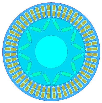
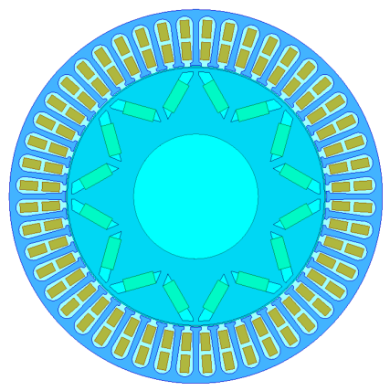
A 2D transient electromagnetic finite-element model of the motor is established in ANSYS Maxwell 2021 R1. For mesh discretization, the stator and rotor core regions are divided with a maximum mesh size of 2 mm, while the air-gap region adopts finer meshing with a maximum element size of 0.5 mm to guarantee electromagnetic calculation accuracy. A mesh convergence study was implemented prior to finalizing the mesh configuration to eliminate the numerical error induced by grid coarseness. Three sets of grid schemes (coarse, medium, and refined) were designed and compared. When adopting the present mesh sizes (2 mm for iron cores and 0.5 mm for air-gap/magnet domains), the relative deviations of average torque and peak permanent magnet loss between adjacent grid groups were less than 0.8%. Further mesh refinement cannot bring obvious improvements in calculation precision, which verifies that the current mesh setup satisfies the convergence criterion for electromagnetic simulation. Sinusoidal three-phase current excitation is applied for the motor model [15]. At the rated speed of 2600 r/min, the electrical period is 0.00288 s, and the simulation time step is set to 1/120 of one electrical period. A total of six electrical cycles are simulated to filter out transient start-up effects and obtain stable steady-state results. The convergence criterion is defined as the relative residual of magnetic vector potential being less than 0.001. Meanwhile, the fluctuations of torque and permanent magnet loss in successive cycles are controlled within 0.5% to ensure the convergence of simulation results. The structural schematic of the motor is shown in Figure 1.
Figure 1.
Schematic diagram of the motor structure.
2.3. Performance Analysis of the Initial Scheme
2.3.1. No-Load Magnetic Field
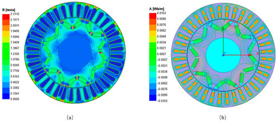
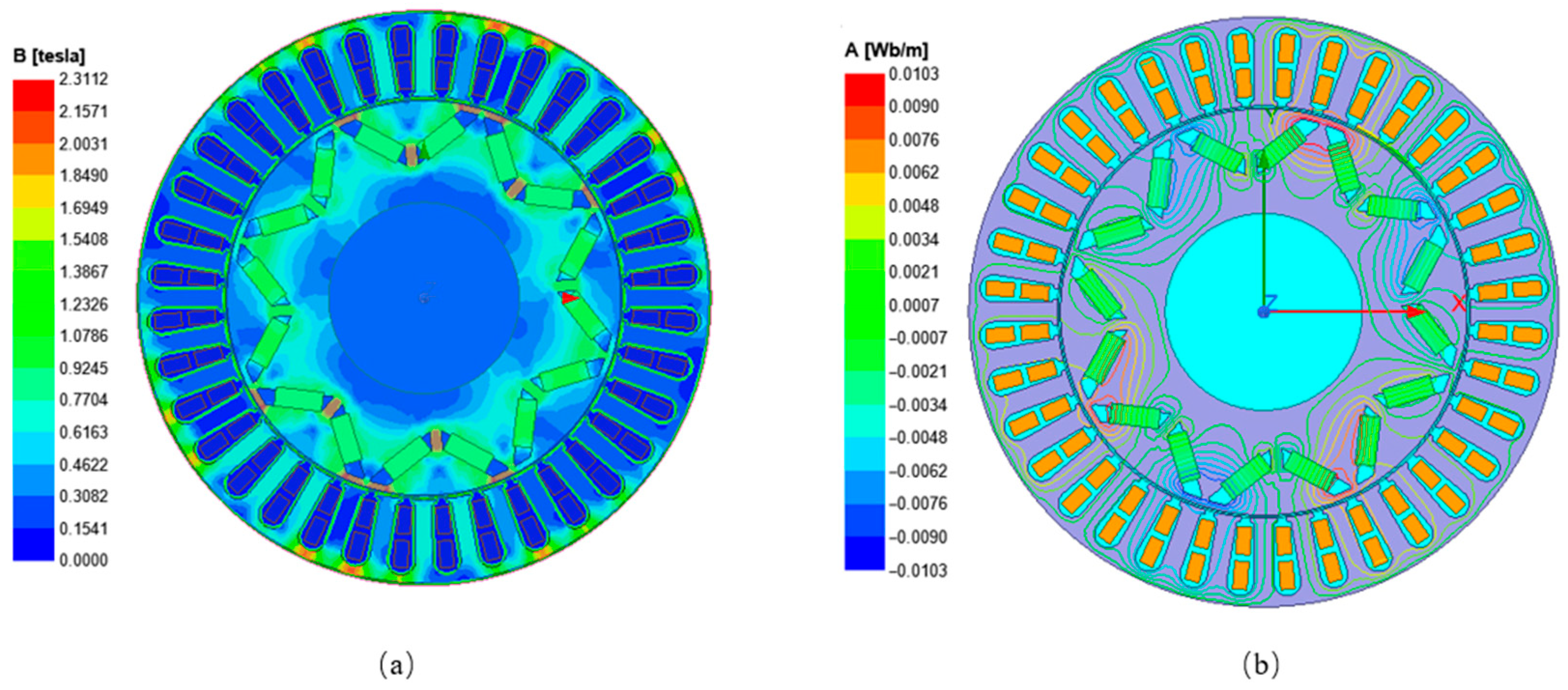
The no-load magnetic field characteristic serves as a crucial indicator for evaluating the rationality of a motor’s magnetic circuit design. Figure 2 presents the cloud diagrams of magnetic flux density and equipotential lines under the no-load condition. It can be observed that magnetic flux flows smoothly along the main magnetic circuit, local peaks of magnetic flux density appear at stator tooth tips, and no overall magnetic saturation occurs in the iron core, which indicates a basically reasonable magnetic circuit design [16].
Figure 2.
Distribution of magnetic flux density and flux lines of the BLDC motor. (a) Magnetic flux density contour; (b) magnetic flux line distribution.
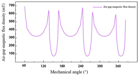
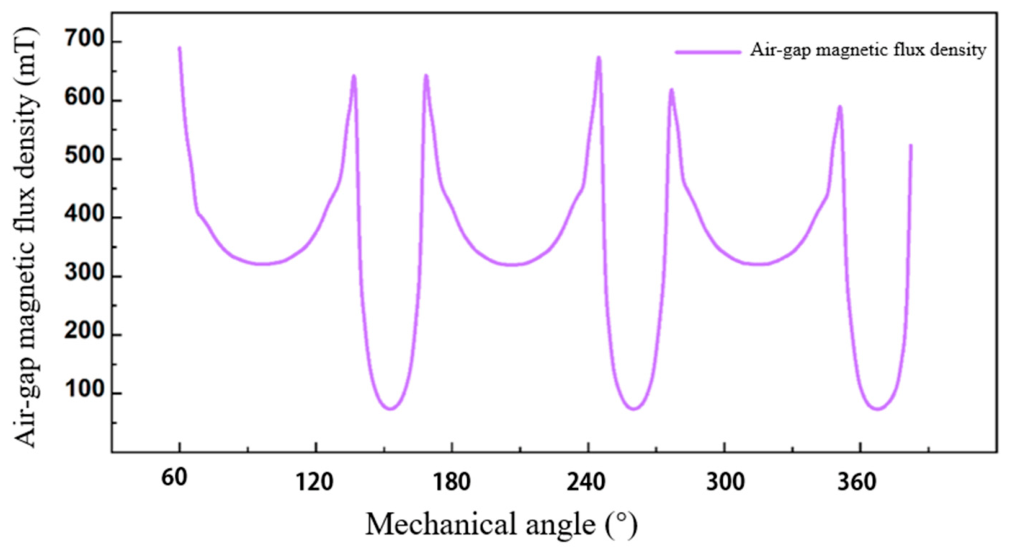
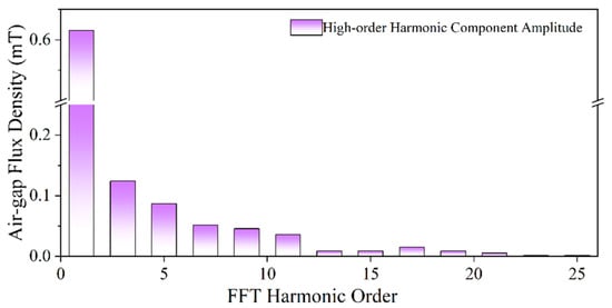
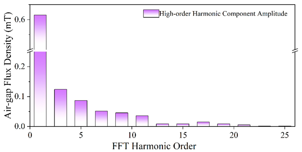
Fourier harmonic decomposition is performed on the air-gap flux density as shown in Figure 3 and Figure 4. The overall waveform approximates a trapezoid and its fundamental amplitude meets the design requirement, yet the contents of high-order harmonics such as the third and fifth orders are relatively high, which can easily induce torque ripple and additional losses and thus requires further optimization.
Figure 3.
Waveform of air-gap magnetic flux density.
Figure 4.
Harmonic amplitude ratio via Fourier decomposition of air-gap flux density.
2.3.2. Torque Characteristics
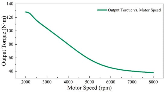
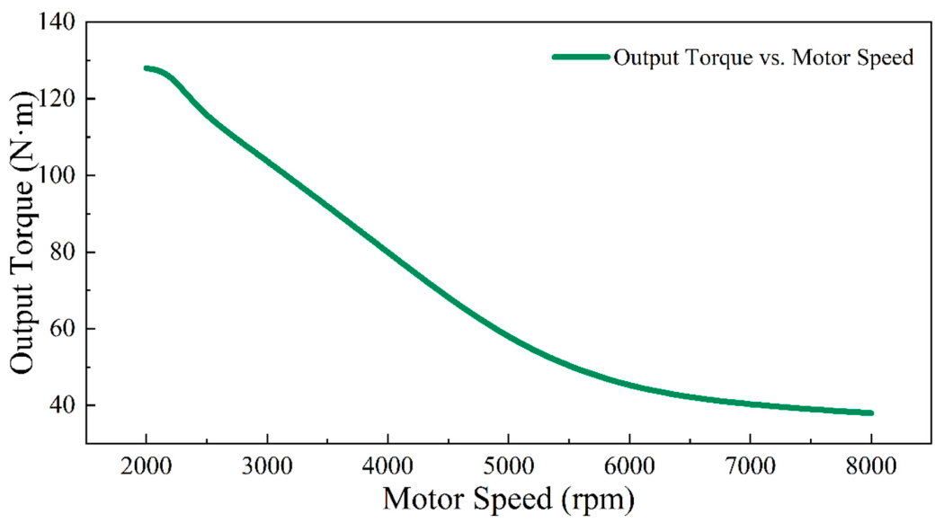
Transient electromagnetic field simulations are carried out under rated operating conditions and the full speed range [17]. The motor continuous rated power is 3.3 kW at 2600 r/min, corresponding to a continuous rated torque of 12.1 N·m. The 127 N·m mentioned in this manuscript is the peak overload torque under transient operating conditions, rather than the continuous rated torque. Such peak torque is adopted as the target of multi-objective optimization, which represents the vehicle-required overload capability during climbing and acceleration. It can be seen from the torque–speed curve in Figure 5 that the prototype exhibits the typical operating characteristics of vehicle drive motors, i.e., high torque at low speeds and constant power at high speeds, which can adapt to common working conditions such as vehicle cruising and climbing.
Figure 5.
Rated torque curves at different rotational speeds.
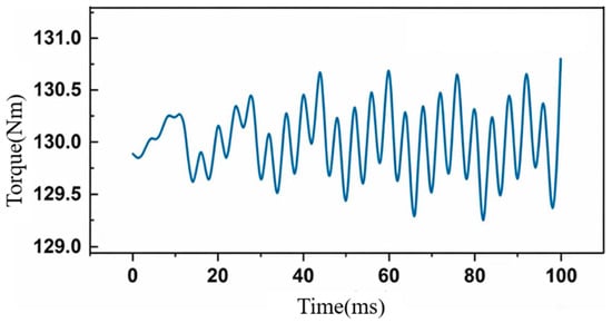
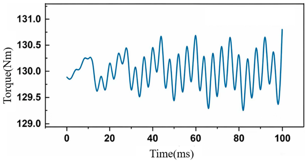
Combined with the no-load cogging torque waveform at the rated speed illustrated in Figure 6, the amplitude of the motor cogging torque is low and complies with the engineering design limit. Combined with the Fourier decomposition results of air-gap flux density presented above, high-order air-gap harmonics will distort the back electromotive force waveform, which imposes a potential adverse impact on the stable operation of the motor.
Figure 6.
No-load torque waveform of the motor at rated rotational speed.
2.3.3. Loss Characteristics
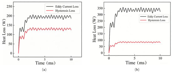
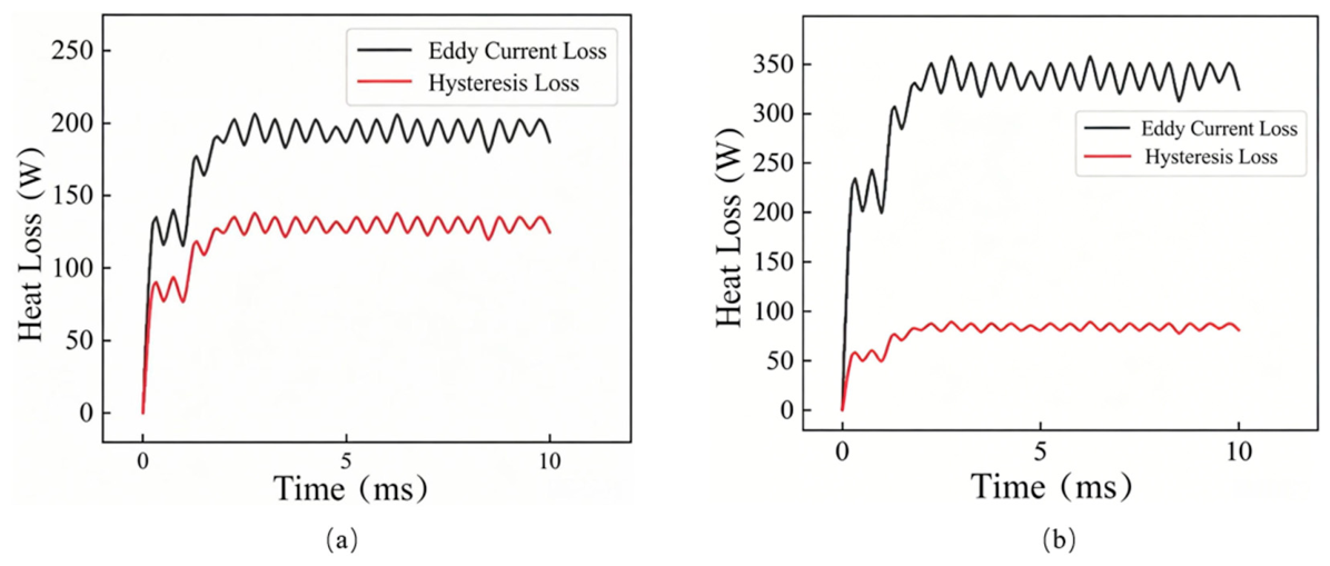
Motor operating losses mainly consist of core hysteresis loss, core eddy current loss and winding copper loss. Table 2 summarizes the loss data at rated and peak rotational speeds. Combined with the time-domain loss curves in Figure 7, it can be concluded that core loss and winding loss are comparable under rated operation and both act as major heat sources. When the speed rises to the peak value, the frequency of alternating magnetic fields increases [18], leading to a sharp growth in eddy current loss and a substantial rise in total permanent magnet loss.
Table 2.
Comparison of motor losses at rated and peak rotational speeds.
Figure 7.
Eddy current and hysteresis loss curves under two different rotational speeds. (a) Rated rotational speed; (b) peak rotational speed.
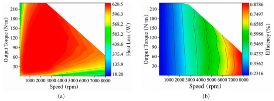
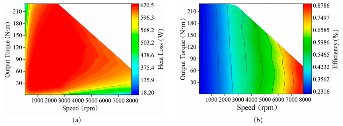
It can be observed from the full operating performance map in Figure 8 that the high-efficiency region of the motor is concentrated in the medium- and low-speed range, while the efficiency drops significantly under high-speed operating conditions. Excessive operating losses degrade the overall efficiency of the motor and may lead to local heat accumulation on permanent magnets, which could introduce demagnetization hazards under continuous heavy-load conditions.
Figure 8.
Contour maps of motor efficiency and permanent magnet loss over full speed–torque range. (a) Permanent magnet heat loss contour; (b) motor efficiency contour.
2.3.4. Summary of Overall Performance
The comprehensive simulation results reveal that the magnetic circuit structure and basic operating characteristics of the eight-pole 48-slot vehicle-mounted BLDC motor can satisfy the basic vehicle application requirements. Nevertheless, restricted by the high-power-density design constraints, the prototype has obvious performance defects. Its rated output torque is insufficient to meet the predetermined design targets, and the permanent magnet thermal loss under high-speed conditions remains excessively high, which reduces the comprehensive operating efficiency and may increase the possibility of magnet demagnetization under sustained high-loss working conditions. In-depth analysis from the perspective of electromagnetic mechanism indicates that the two critical performance deficiencies above originate from the unreasonable distribution of the air-gap magnetic field. The initial structure delivers a low fundamental amplitude of air-gap flux density, which restricts the full utilization of the excitation capacity of the main magnetic circuit. Moreover, the mismatched stator slot parameters and rotor pole dimensions lead to a high proportion of slot leakage flux and insufficient effective excitation flux, greatly reducing the magnetic load during electromechanical energy conversion and limiting the rated torque output of the motor. Meanwhile, the tooth harmonics generated by the stator slotting effect superpose with the spatial harmonics induced by the edge effect of rotor poles, introducing abundant high-order harmonics into the air-gap magnetic field. These harmonics induce high-frequency eddy currents both on the surface and inside the permanent magnets and produce additional eddy current losses. In addition, the higher the motor speed, the larger the alternating frequency of the magnetic field, and the more obvious the growth trend of permanent magnet loss. The key structural parameters of the stator and rotor directly determine the magnetic field distribution and output characteristics of the motor, and there is an inherent trade-off between torque improvement and loss suppression. Simply enhancing excitation to boost torque performance will further aggravate magnetic field harmonic distortion and raise permanent magnet loss, making it impossible to achieve optimal performance by adjusting a single parameter. Accordingly, this paper takes increasing the rated torque and reducing the peak thermal loss of permanent magnets as dual optimization objectives [19]. The collaborative optimization of multiple structural parameters is adopted to reconstruct the air-gap magnetic field distribution, resolve the trade-off between torque and loss, and finally realize the simultaneous optimization of the motor dynamic performance and loss characteristics.
3. Multi-Objective Optimization Method for the Motor
3.1. Overall Optimization Scheme
3.1.1. Optimization Objectives and Constraints
To meet the multi-objective optimization demands of maximizing torque and minimizing loss, the weighted normalization method is adopted in this study to construct a comprehensive evaluation function [20]. The optimization objectives simultaneously consider the cruising torque at 2600 r/min and peak permanent magnet loss at the maximum speed of 8000 r/min to avoid optimization bias toward a single operating point. Considering that vehicle driving scenarios give priority to guaranteeing the torque output capacity of the motor, weight coefficients of 0.6 and 0.4 are assigned to the rated output torque and permanent magnet thermal loss, respectively. After normalization, the comprehensive evaluation function is expressed as Equation (1), which provides a quantitative evaluation criterion for the optimization solution of the subsequent multi-objective optimization algorithm:
where the evaluation criterion is defined in the formula, Ta0 represents the rated output torque, and PL0 denotes the average thermal loss of permanent magnets.
The weight coefficients of rated torque and permanent magnet peak thermal loss are set to 0.6 and 0.4 rather than arbitrarily assigned with clear engineering support: as the core indicator determining vehicle acceleration, climbing capacity and low-speed dynamic performance, output torque is given a higher weight of 0.6, while permanent magnet thermal loss, which mainly limits high-speed thermal safety and prevents irreversible magnet demagnetization, serves as a secondary indicator with a weight of 0.4. To verify the robustness of Pareto-optimal solutions and avoid random optimization results from fixed weights, sensitivity analysis with a step size of 0.1 is conducted where torque weight varies from 0.4 to 0.8, forming five weight pairs of (0.4, 0.6), (0.5, 0.5), (0.6, 0.4), (0.7, 0.3) and (0.8, 0.2), and the corresponding optimized performance metrics are summarized in Table 3; data in the table show that higher torque weights bring larger torque improvement but weaker loss suppression, the original (0.6, 0.4) scheme achieves a 9.01% rise in rated torque and a 16.50% drop in peak permanent magnet loss to simultaneously satisfy the motor’s high power density demand and thermal safety threshold, whereas weight pairs above (0.7, 0.3) lead to loss reduction rates below 8% and severe high-speed demagnetization risks, and weight pairs below (0.5, 0.5) only deliver torque growth lower than 7% that fails vehicle dynamic requirements. Within the weight combinations examined in this work, the weighting pair of 0.6 and 0.4 achieves a favorable overall trade-off between torque enhancement and permanent magnet loss reduction for the 3.3 kW traction BLDC motor studied in this paper.
Table 3.
Performance comparison of optimized motors under different weight coefficients.
To suppress vibration and noise during operation, torque ripple and cogging torque are introduced as hard constraints into the multi-objective optimization model, and the detailed constraint settings and corresponding performance variations before and after optimization are analyzed as follows:
In the established multi-objective optimization framework, torque ripple and cogging torque are defined as mandatory hard constraints rather than optimization objectives to guarantee smooth motor operation, where the torque ripple coefficient is limited to no more than 5% according to the automotive industry standard threshold and the ratio of cogging torque to rated torque is restricted within 2%. All Pareto-optimal solutions screened by the NSGA-II algorithm must comply with the two above-mentioned inequality constraints, and unqualified individuals will be eliminated in each population update iteration. The torque ripple of the original prototype is 3.61%, which slightly increases to 4.23% after optimization, and both values are within the 5% limit; the harmonic amplitude decomposition results of electromagnetic torque for the original and optimized schemes are summarized in Table 4, which records the amplitudes of each harmonic component and corresponding variation trend. The low-order second and third harmonics increase marginally after optimization, which accounts for the slight growth of total torque ripple, whereas high-order tooth harmonics from the sixth order onward are effectively suppressed. Meanwhile, the peak cogging torque of the original prototype is 1.82 N·m, accounting for 1.43% of the rated torque, and this value drops to 1.46 N·m (1.08% of rated torque) in the optimized model, demonstrating that the slot–pole matching optimization method can effectively reduce cogging torque fluctuation. Although moderate growth of torque ripple occurs after optimization, it is still strictly controlled below the 5% engineering threshold, and the simultaneous promotion of output torque and loss reduction is achieved on the premise of meeting the vibration and noise constraint requirements.
Table 4.
Harmonic amplitude decomposition of electromagnetic torque for the initial and optimized motors.
3.1.2. Optimization Variables
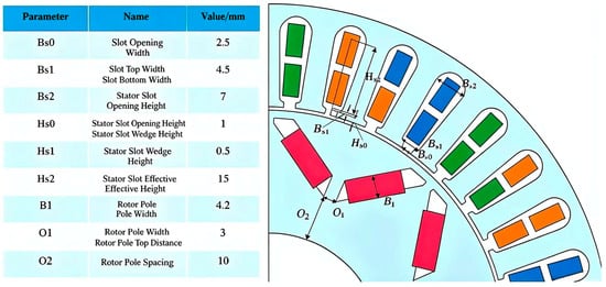
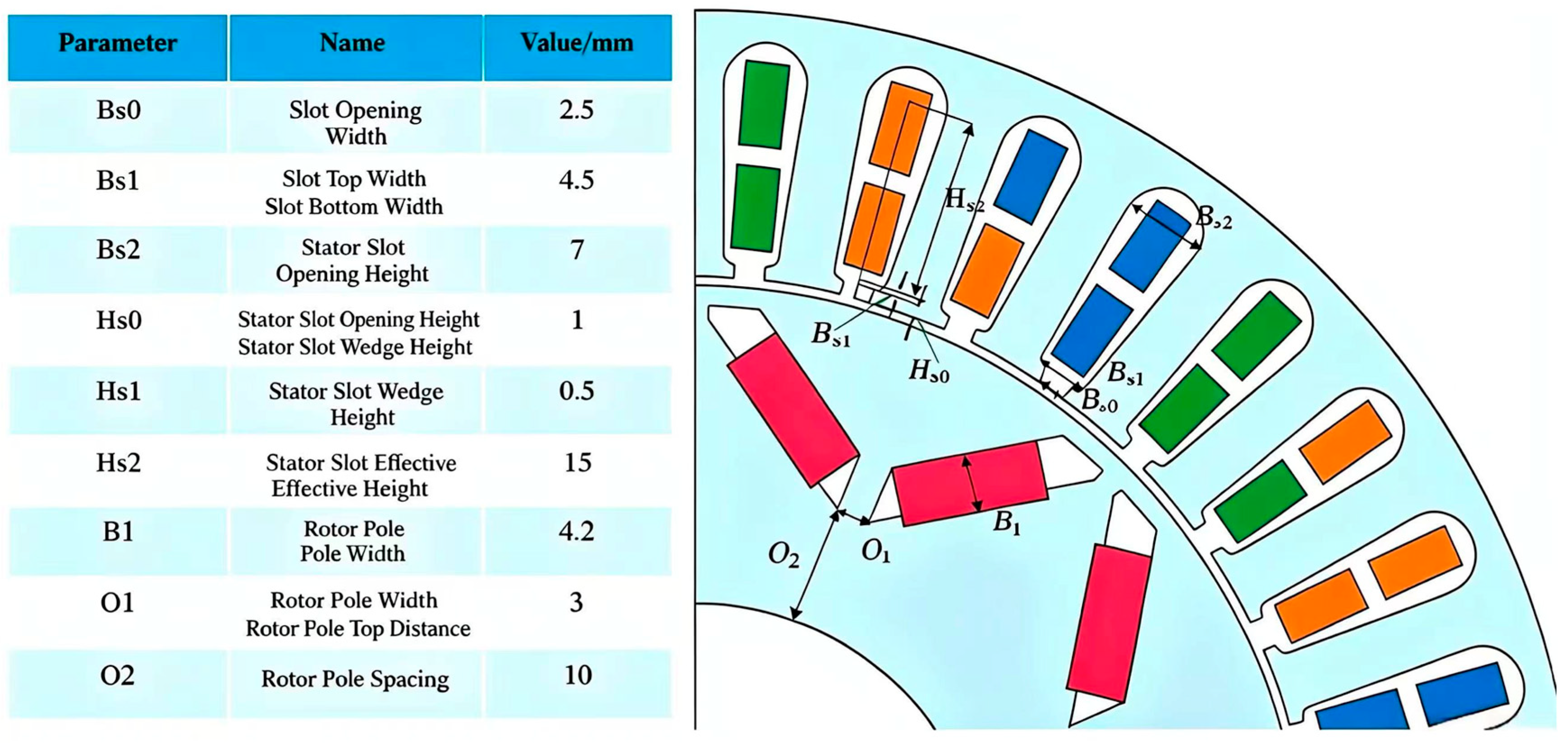
The key structural parameters of the stator and rotor directly determine the magnetic circuit path, air-gap magnetic field distribution and harmonic characteristics, and act as the dominant factors affecting torque output and permanent magnet thermal loss. Nine critical structural parameters are selected as the initial optimization variables in this work, and their definitions and physical meanings are illustrated in Figure 9. The stator-related structural parameters mainly include the slot opening width Bs0, slot top width Bs1, slot bottom width Bs2, stator slot opening height Hs0, stator wedge height Hs1 and effective stator slot height Hs2. The rotor-side parameters cover the rotor pole width B1, rotor pole tip distance O1 and rotor pole spacing O2.
Figure 9.
Schematic diagram of key structural optimization parameters.
3.1.3. Optimization Flowchart
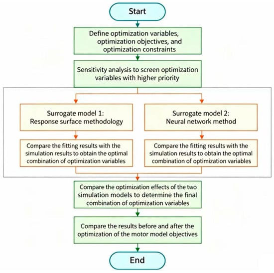
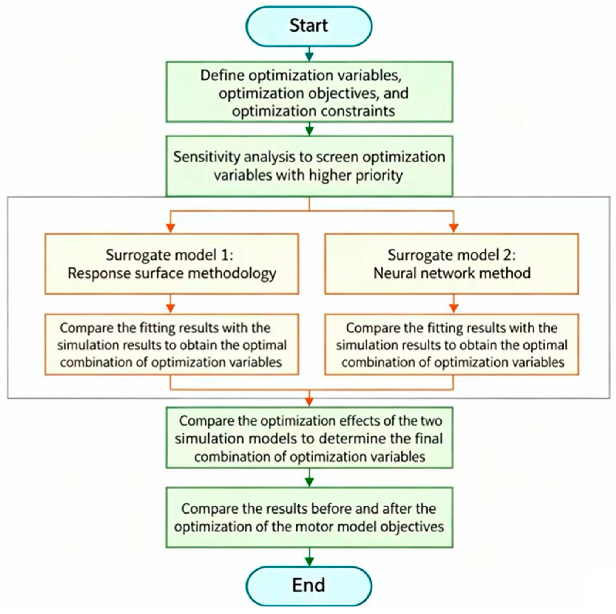
The overall optimization procedure is depicted in Figure 10. A full technical framework consisting of variable screening, surrogate model construction and simulation verification is established in this optimization work. First, the optimization variables and dual optimization objectives are determined [21]. Parameter sensitivity analysis is then performed to screen high-priority variables so as to reduce optimization dimensions and computational burden. Two surrogate models, namely response surface methodology (RSM) and a BP neural network, are constructed separately to fit the nonlinear mapping relationships between design variables and optimization objectives [22]. The surrogate model with superior fitting accuracy is selected through comparative analysis of multiple schemes. The NSGA-II algorithm is adopted to implement global multi-objective optimization and obtain the Pareto-optimal solution set. Finally, the simulated electromagnetic performances before and after optimization are compared to verify the effectiveness of the proposed optimization strategy.
Figure 10.
Schematic diagram of the optimization-design process.
3.2. Parameter Sensitivity Analysis
To quantify the influence degree of each parameter on motor performance, the sensitivity coefficient is adopted as the evaluation index [23], and its calculation formula is expressed as follows:
where Si denotes the sensitivity coefficient of the i-th parameter, and ΔXi and ΔY represent the variations in the structural parameter and the performance indicator, respectively.
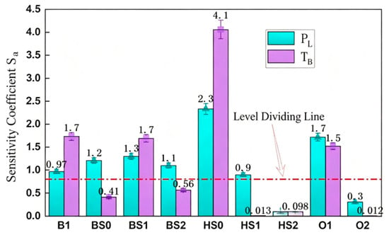
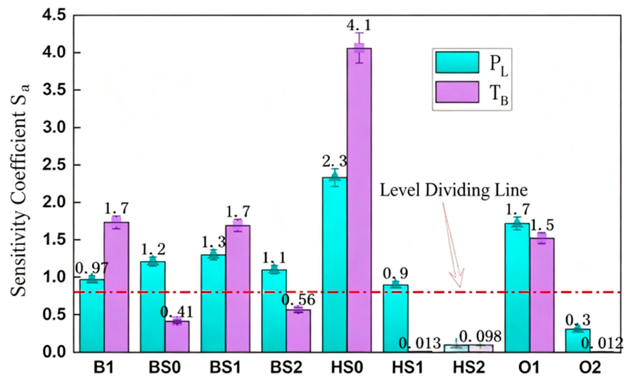
The Taguchi method is adopted to design orthogonal experiments, and the sensitivity coefficient of each parameter is calculated according to Equation (2). The corresponding results are summarized in Table 5 and illustrated in Figure 11. It can be observed that the influence degrees of various parameters on the optimization objectives show an obvious two-level differentiation characteristic. The stator slot opening height Hs0 possesses the highest sensitivity coefficients for both optimization objectives, with a value of 2.33 for PL and 4.06 for Ta, which indicates that Hs0 is the most dominant parameter determining motor performance. In addition, the sensitivity coefficients of the rotor pole tip distance O1, slot opening width Bs0, rotor pole width B1 and slot top width Bs1 all exceed 1.0, demonstrating their remarkable effects on the optimization objectives.
Table 5.
Sensitivity analysis results of optimization parameters.
Figure 11.
Sensitivity coefficients of optimization parameters for PM loss and rated torque.
Differences in the sensitivity of various structural parameters reflect their distinct modulation capacities for the air-gap magnetic circuit of the motor. Among all parameters, the stator slot opening height Hs0 possesses the highest sensitivity. It can directly adjust the fluctuation characteristics of air-gap permeance, simultaneously affecting the fundamental amplitude of air-gap flux density and the intensity of stator tooth harmonics, and thus imposes a remarkable modulation effect on both the torque output of the motor and the eddy current loss of permanent magnets. Rotor parameters B1 and O1 rank second in sensitivity, which reshape the air-gap magnetic field waveform, fundamental wave proportion and harmonic content by adjusting the pole arc structure and magnetic field distribution near the pole edges. In contrast, parameters including slot bottom width and effective stator slot height mainly dominate the stator magnetic circuit and exert a weak direct regulatory effect on the air-gap magnetic field, accompanied by relatively low sensitivity and limited contribution to the optimization objectives.
In accordance with the above sensitivity rules, hierarchical screening is performed on the optimization parameters in this work. Four parameters (Hs0, Bs1, B1, and O1) with a total contribution rate higher than 85% are selected as core optimization variables, and the remaining parameters are fixed at their optimal initial values for dimensionality reduction. The number of original nine design parameters is reduced to four, which cuts the simulation computational burden by more than 55% and significantly improves the computational efficiency of the subsequent multi-objective optimization process.
The primary and secondary optimization variables are summarized in Table 6 and Table 7, which define the boundary conditions for the subsequent multi-objective optimization of primary variables.
Table 6.
Main optimization variables.
Table 7.
Secondary optimization variables and their optimal values.
3.3. Establishment of Surrogate Model
3.3.1. Experimental Design for Surrogate Model
Following the aforementioned parameter sensitivity analysis and screening, four core structural parameters are selected as optimization variables: the rotor pole width B1, stator slot top width Bs1, stator slot opening height Hs0 and rotor pole tip distance O1. A highly nonlinear and strongly electromagnetically coupled mapping relationship exists between these optimization variables and the dual optimization objectives of maximizing rated torque and minimizing the peak thermal loss of permanent magnets [24]. It is difficult to construct a high-precision mathematical model relying only on analytical magnetic circuit equations. Therefore, surrogate models are introduced to fit the intrinsic correlation between structural parameters and performance indicators, serving as an efficient numerical solution tool for global optimization via subsequent intelligent optimization algorithms. The general fitting framework of the surrogate model is described as follows:
where Y(X) is the actual electromagnetic response output from finite-element simulations; F(X) stands for the fitting function of the developed surrogate model; and e(X) denotes the model fitting residual.
The sampling scheme directly determines the fitting accuracy of the surrogate model. In this study, four sampling methods—uniform design, orthogonal experiment, Monte Carlo sampling and Latin hypercube sampling—are compared, and Latin hypercube sampling is adopted for sample collection [25]. This method performs stratified uniform sampling for parameters in each dimension, which can fully cover the parameter design space with a small number of samples and accurately capture the nonlinear coupling characteristics among multiple variables, balancing sample representativeness and simulation efficiency.
The sampling ranges are defined for the four primary optimization variables, and a total of 24 sets of finite-element simulation samples are obtained, as listed in Table 8. The rated torque ranges from 112.0 to 174.6 N∙m, and the peak thermal loss of permanent magnets varies between 355.3 W and 628.2 W. The obtained dataset can comprehensively characterize the influence of parameter variations on the optimization objectives, thus providing sufficient data support for the construction of the surrogate model.
Table 8.
Simulation results of Latin hypercube sampling.
3.3.2. Response Surface Model
Prior to intelligent multi-objective optimization, it is necessary to establish an explicit fitting function between optimization variables and performance objectives. The response surface methodology (RSM) constructs a polynomial approximation of the implicit electromagnetic mapping relationship using the response data of sampling points, which enables continuous analysis over the entire parameter range and is well suited for addressing multivariate nonlinear optimization problems of electric motors. Central Composite Design and Box–Behnken Design (BBD) are two classical sampling strategies for response surface analysis, both of which can efficiently solve the coefficients of second-order polynomials [26]. In particular, all sampling points of the BBD scheme are distributed within the parameter design domain, delivering superior fitting stability. This method is applicable to modeling with 2–5 variables and has been widely adopted in the structural optimization of motors.
Considering the range constraints of the four-dimensional optimization variables in this study, the full second-order polynomial is constructed as the surrogate model based on mathematical statistical regression theory to reduce the fitting deviation caused by boundary extrapolation. This model can simultaneously characterize the linear effects of individual variables, the nonlinear effects of single parameters, as well as the coupling interaction effects among multiple structural parameters. The general mathematical expression is given in Equation (4):
where each coefficient denotes the regression coefficient; k is the total number of optimization variables; Xi and Xj represent the normalized input structural parameters; and ε refers to the model fitting residual. The linear terms describe the linear influence of each parameter on motor performance, the quadratic terms characterize the inherent nonlinear variation rule of a single parameter, and the cross-interaction terms reflect the coupling effects among multiple variables.
Based on the 24 groups of sample datasets obtained via Latin hypercube sampling in the previous section, the least-squares multiple regression method is adopted to fit the peak thermal loss of permanent magnets PL and the rated output torque Ta separately. Two independent second-order response surface regression equations are derived as shown in Equations (5) and (6), thereby completing the solution and establishment of the dual-objective response surface surrogate model.
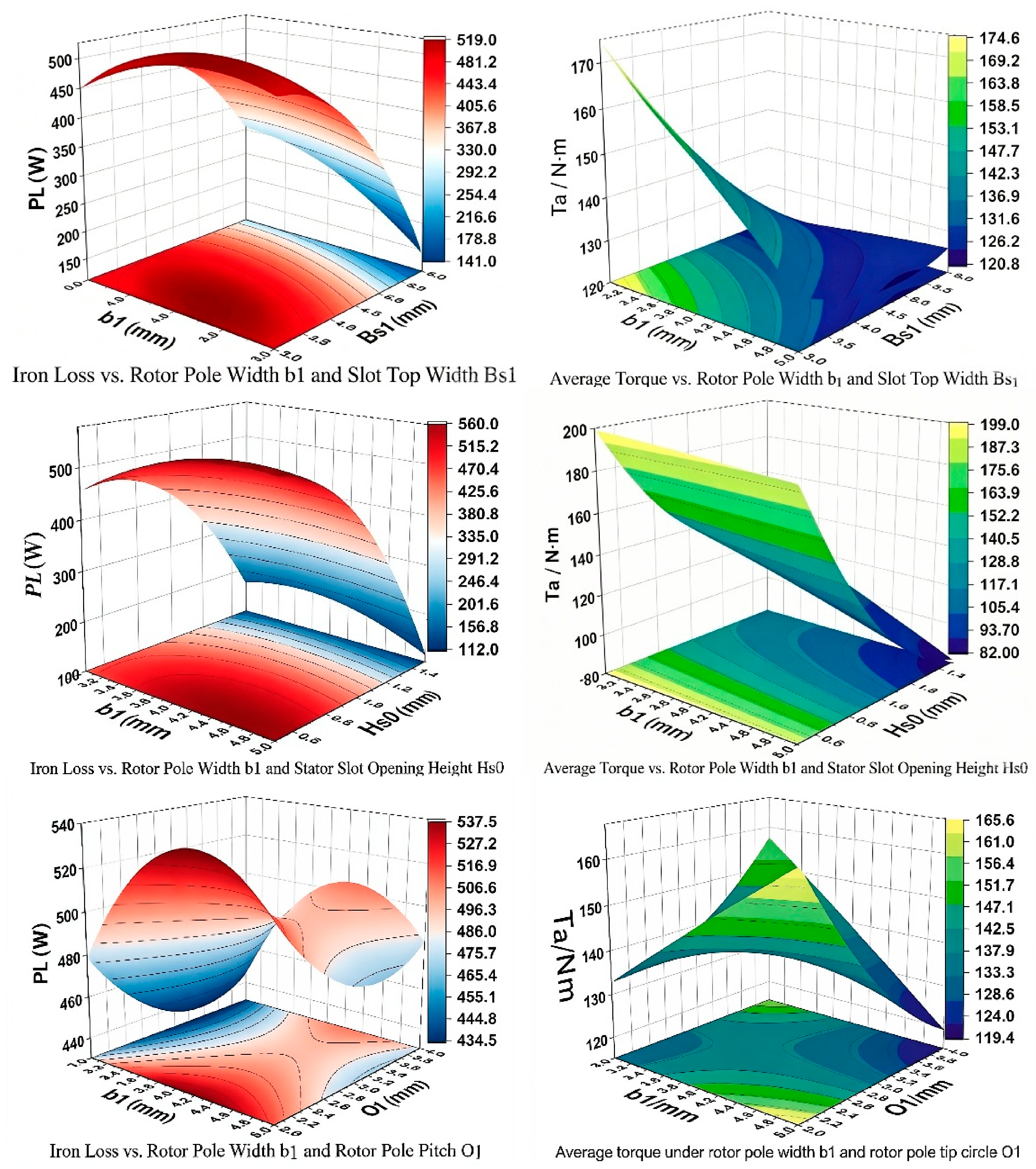
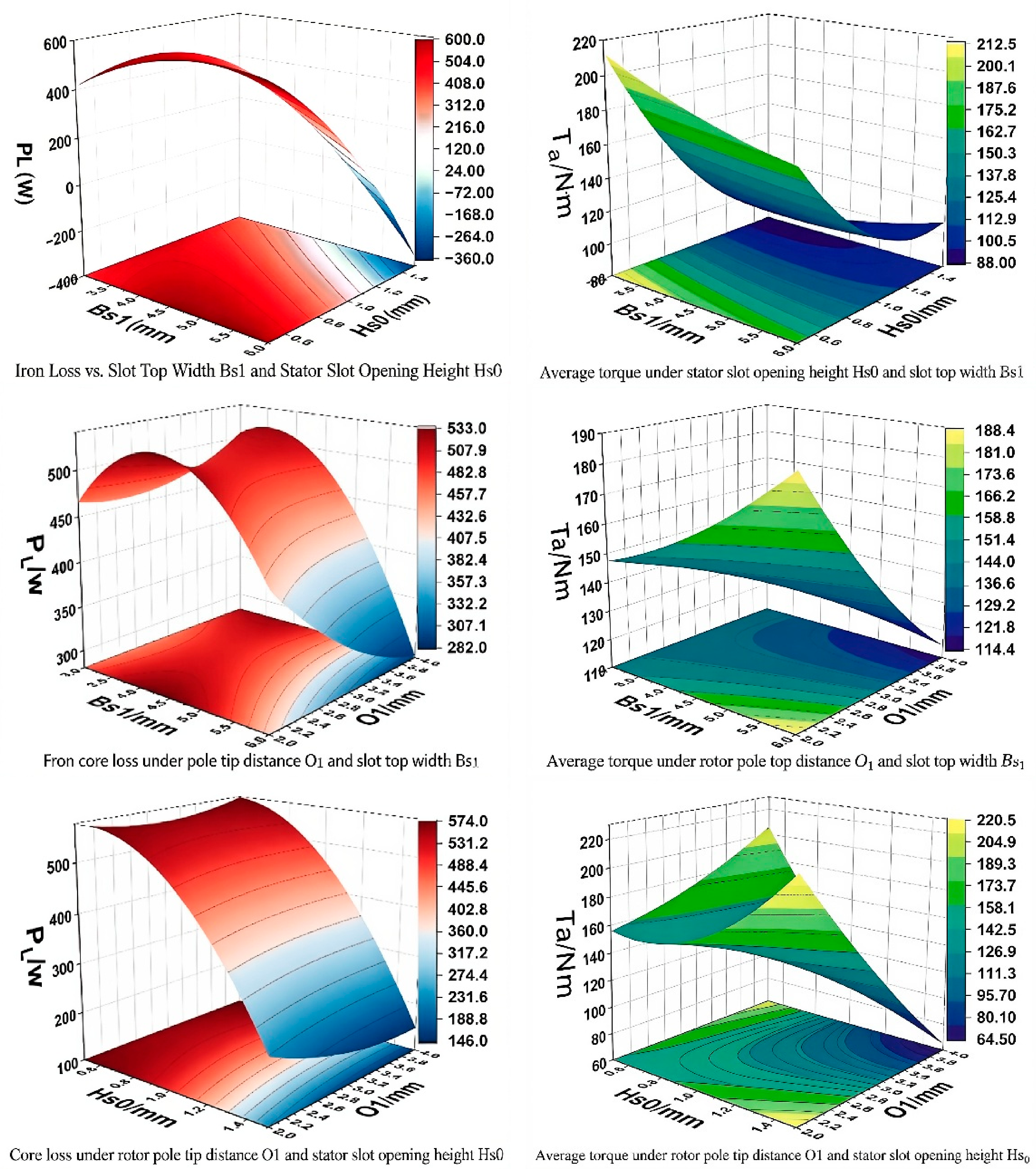
Performance prediction is carried out using the above second-order regression equations of PL and Ta, and three-dimensional response surfaces are constructed accordingly. The projection of these 3D surfaces can intuitively illustrate the variation trends of optimization objectives under the single-variable effect and two-variable coupling effect, which clearly reveals the nonlinear influence laws and interaction mechanisms of four parameters (rotor pole width B1, stator slot top width BS1, stator slot opening height HS0, and rotor pole tip distance O1) on permanent magnet thermal loss and rated output torque. The obtained results provide an intuitive parameter–performance mapping basis for the subsequent multi-objective optimization.
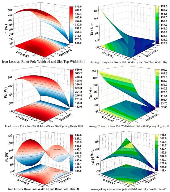
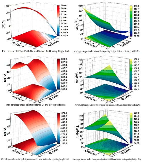
Figure 12 presents a set of three-dimensional response surfaces corresponding to pairwise coupling of key optimization variables, which can intuitively reveal how parameter interactions affect the optimization objectives. Under the combined effect of rotor pole width B1 and stator slot top width BS1, the thermal loss of permanent magnets varies in a convex function pattern that first decreases and then increases with the growth of B1, while the rated output torque rises first and then declines as B1 increases, indicating that both performance indicators have their respective optimal parameter ranges. The stator slot opening height HS0 exhibits the highest sensitivity to the two performance metrics: as HS0 increases, the permanent magnet thermal loss rises rapidly in a nonlinear manner, and the output torque surges sharply before gradually reaching saturation. This variation law is consistent with the results of the preceding parameter sensitivity analysis. Significant interactive effects exist between the rotor pole tip distance O1 and BS1 as well as HS0. The strong coupling characteristics among these parameters fully demonstrate that optimal overall performance cannot be achieved merely by adjusting a single variable, which verifies the necessity and engineering value of implementing multivariate collaborative optimization.
Figure 12.
Group of 3D response surfaces for permanent magnet loss and rated torque under pairwise coupling of key parameters.
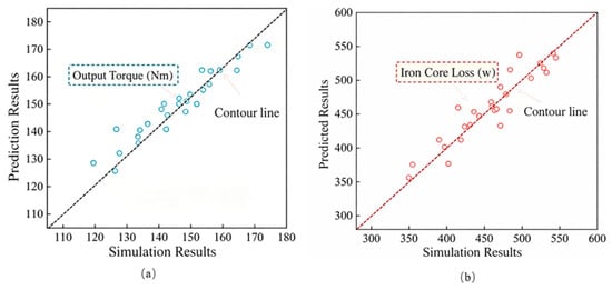
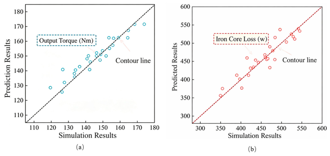
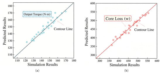
Figure 13 shows the scatter plots comparing the predicted values from the response surface model with the true values obtained by finite-element simulation. Most sample points are evenly distributed along the ideal 45° fitting line, which verifies that the second-order response surface model achieves favorable fitting accuracy for the rated torque Ta and permanent magnet thermal loss PL within the conventional parameter range. Nevertheless, under extreme operating conditions where PL > 550 W, the sample points deviate markedly from the ideal equivalence line, accompanied by a remarkable increase in model prediction error. This result reveals that the second-order polynomial response surface has limitations in characterizing the strongly nonlinear and multi-parameter coupled mapping relationship of the motor electromagnetic system. Reliable accuracy can only be guaranteed within a limited parameter domain, and the performance variation rules in extreme regions cannot be accurately described. Accordingly, a surrogate model with superior fitting performance is required for subsequent modeling.
Figure 13.
Comparison between predicted values of response surface model and true values from finite-element simulation. (a) Output torque; (b) iron core loss.
3.3.3. BP Neural Network Model
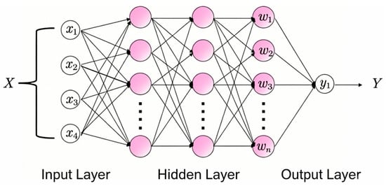
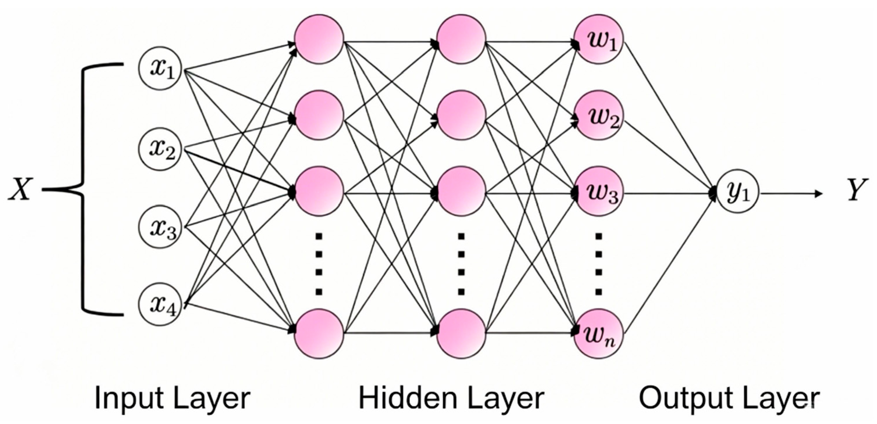
Back Propagation (BP) neural networks possess excellent nonlinear fitting capability, which makes them suitable for motor optimization scenarios featuring strong coupling among multiple design parameters. In this study, a three-layer fully connected BP neural network is adopted for surrogate modeling [27]. The input layer corresponds to the four core optimization variables, the hidden layer contains 12 neurons, and the output layer outputs the dual objectives of rated torque and peak thermal loss of permanent magnets [28]. The topological structure of the established BP neural network is illustrated in Figure 14.
Figure 14.
Schematic diagram of surrogate neural network structure.
Considering the limited number of sample cases obtained by finite-element calculation, the number of hidden-layer neurons is set to 12. Although the neuron quantity is close to the sample size, reasonable regularization is adopted during training to suppress overfitting. Five-fold cross-validation is implemented to objectively assess the generalization ability of the network. The total 24 groups of sample data are divided into five non-overlapping subsets. In each fold, four subsets are used for model training and the remaining one subset serves as the test set. The training–test procedure circulates five times with different data partitions. The mean value of mean squared error and coefficient of determination R2 over five test folds are calculated to quantify the predictive performance. The cross-validation results show that the average R2 for torque prediction and loss prediction remain above 0.95, demonstrating acceptable generalization capability without obvious overfitting.
For network training, the ReLU activation function is adopted for the hidden layer to capture nonlinear electromagnetic characteristics, while the linear activation function is used for the output layer to realize continuous regression of torque and loss values. The Adam optimization algorithm is selected as the training optimizer with an initial learning rate of 0.001. All 24 groups of input and output sample data are normalized to the range [0, 1] via min-max scaling to eliminate the magnitude difference between different physical quantities. The maximum training epoch is set to 1000, and an early stopping criterion is applied to prevent overfitting: training terminates automatically if the test set loss does not decrease for 50 consecutive iterations. A five-fold cross-validation strategy is adopted to divide all samples into training subsets and independent validation subsets, which avoids random splitting bias and reliably evaluates the generalization performance of the neural network.
Before adopting the 8:2 train–test split ratio, we compared several common partition schemes including 7:3, 8:2 and 9:1 to analyze how sample allocation affects prediction accuracy and generalization ability. Under the total sample size of only 24 groups, the 7:3 scheme leaves merely 7 samples for testing, and the limited test data leads to large random fluctuations of evaluation indicators; the 9:1 split retains only 2 validation samples, which cannot objectively reflect the model’s generalization performance and carries a high risk of accidental evaluation results. The 8:2 division allocates 19 training samples and 5 independent test samples, which balances sufficient training data for nonlinear fitting and enough test samples for reliable performance assessment, fully proving that the 8:2 split is the most appropriate choice under the current small-sample condition.
From the physical nature of nonlinear approximation, the accuracy discrepancy between the two types of surrogate models stems from their distinct nonlinear fitting capacities. The second-order response surface model relies merely on polynomial fitting, which can only characterize linear terms, quadratic terms and second-order interaction effects of design parameters. Consequently, it fails to describe the prevalent high-order nonlinearity and strong multi-parameter coupling inherent to motor electromagnetic systems. Especially within the extreme parameter range, magnetic circuit saturation and harmonic coupling effects are drastically intensified, leading to an obvious degradation in fitting accuracy. In contrast, benefiting from multi-layer neurons and nonlinear activation functions, the BP neural network is capable of approximating complex continuous nonlinear mappings. It can effectively capture high-order parameter coupling, magnetic saturation and harmonic interaction characteristics, thereby maintaining stable and favorable fitting accuracy across the entire parameter domain. Therefore, this approach is more suitable for surrogate modeling of strongly nonlinear motor electromagnetic systems.
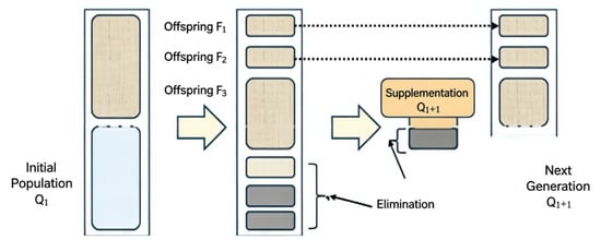
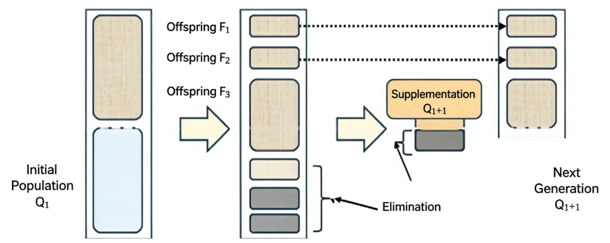
The 24 groups of Latin hypercube sampling datasets obtained in the previous section are adopted for modeling and divided into a training set and a test set at a ratio of 8:2. After network training, the trained BP neural network is combined with the NSGA-II algorithm to implement multi-objective optimization [29]. By introducing fast non-dominated sorting, elitist preservation and crowding distance operators, this algorithm effectively addresses the drawbacks of slow convergence and premature loss of optimal solutions in conventional genetic algorithms. The iterative procedure of the NSGA-II algorithm is illustrated in Figure 15.
Figure 15.
Iterative update flow of population with elite preservation strategy.
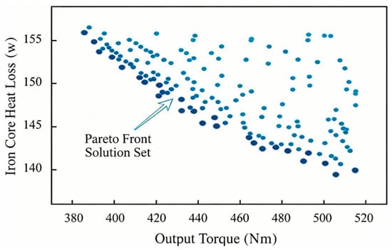
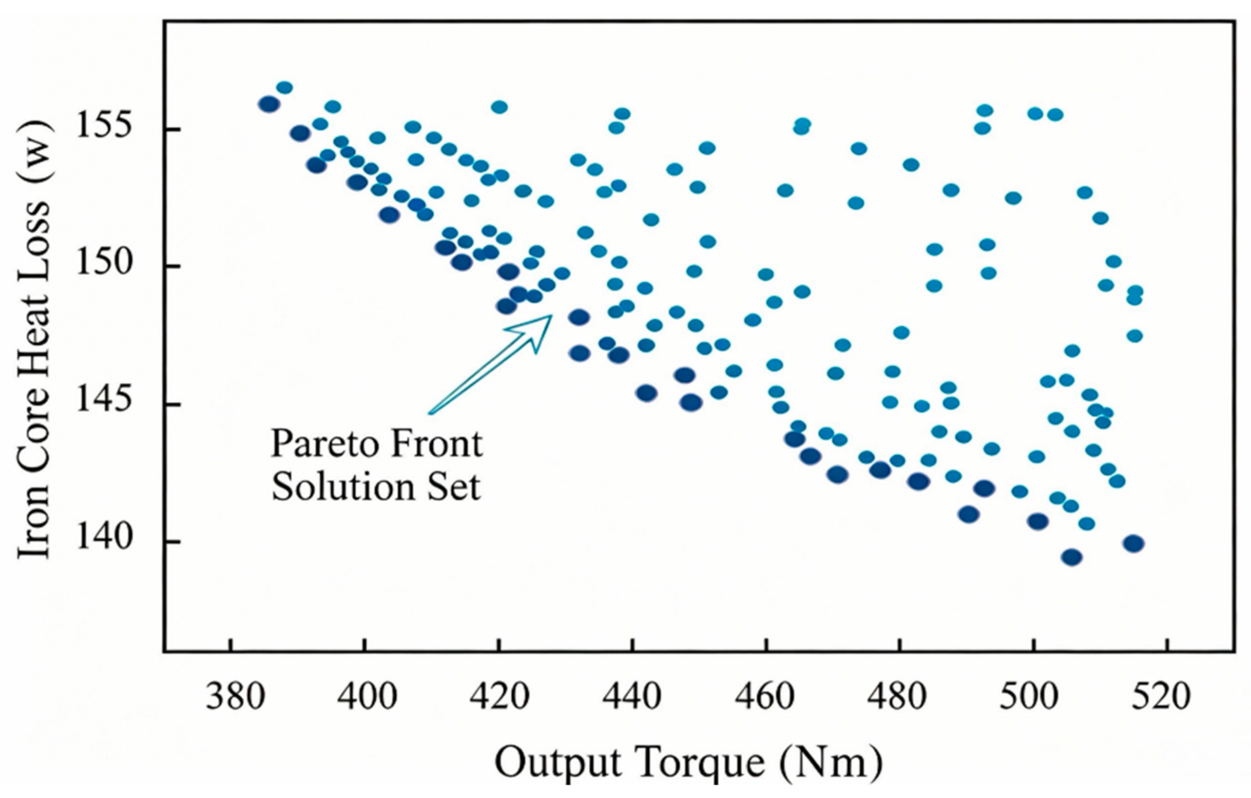
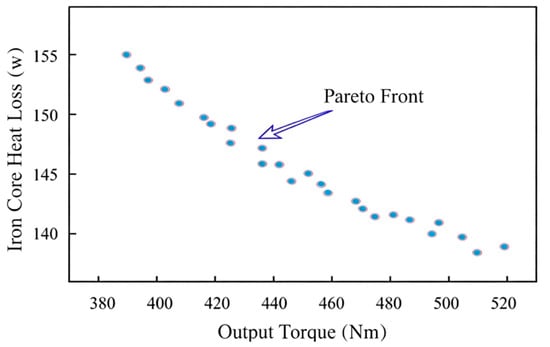
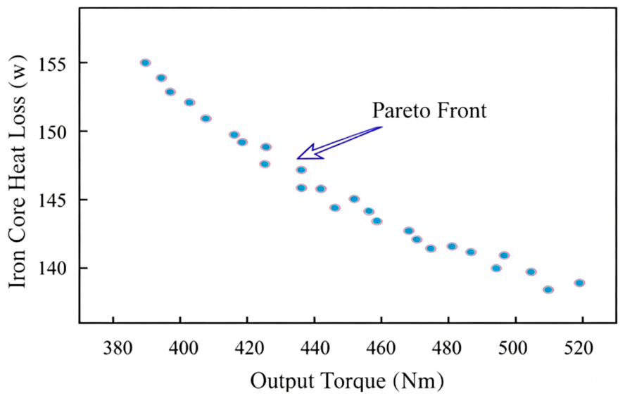
The maximum number of algorithm iterations is set to 1000 in this optimization. The distribution of all populations after 1000 elitist iterations is presented in Figure 16, where most individuals correspond to dominated inferior solutions and the points marked in red represent the non-dominated Pareto-optimal solution set. After eliminating all inferior solutions, the optimal Pareto front is plotted separately in Figure 17. It can be observed that there exists an obvious conflicting trade-off relationship between output torque and core loss, whereby a higher output torque is accompanied by greater core loss.
Figure 16.
Population distribution and pareto front for iron loss and output torque at 1000 iterations.
Figure 17.
Pareto-optimal front curve of iron core loss and output torque after 1000 iterations. Note: data points in this plot are performance values predicted by the BP neural network surrogate model during optimization iteration.
Table 9 lists the 22 sets of non-dominated optimal solutions obtained after iterative optimization. An evident trade-off relationship can be observed between the rated torque and the thermal loss of permanent magnets: the improvement in torque is generally accompanied by an increase in loss, and different parameter combinations can satisfy the requirements of various operating conditions. Among these solutions, the seventh group achieves a rated torque of 169.4 N∙m, while the eleventh group restricts the thermal loss to 442.9 W.
Table 9.
Pareto front solutions obtained after 1000 iterations of optimization.
It should be noted that the Pareto-front points shown in Figure 16 and Figure 17 are predicted values obtained from the BP surrogate model. The torque and loss data listed in Table 9 are recalculated high-fidelity results of selected Pareto candidates by finite-element verification. Minor deviations between two groups of data are inevitable due to the prediction error of the surrogate model.
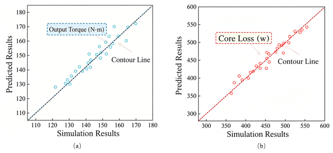
To verify the model accuracy, the prediction results of the BP neural network are compared with finite-element simulation data. Figure 18 illustrates the comparison between the predicted values from the BP neural network and the true values obtained via finite-element simulation, where the dashed line at 45° denotes the ideal unbiased fitting line. All sample points are closely and evenly distributed alongside this ideal line. Quantitative calculation reveals that the prediction accuracy of the established model reaches 92% for the rated torque Ta and 96% for the permanent magnet thermal loss PL. Slight prediction deviations only occur within the extreme ranges of the two performance indicators, indicating a minor decline in the model’s fitting capacity under boundary operating conditions. Nevertheless, the overall prediction error is controlled within 5%.
Figure 18.
Comparison between predicted values of neural network surrogate model and true values from finite-element simulation. (a) Output torque; (b) core loss.
3.4. Model Accuracy Evaluation
To select the optimal surrogate model suitable for this optimization task, two quantitative indicators, namely the coefficient of determination R2 and mean square error (MSE), are adopted to evaluate the accuracy of the second-order response surface model and the BP neural network model [30]. The coefficient of determination reflects the degree of fitting between model predicted values and finite-element simulation values; a value closer to 1 indicates a better fitting performance. The mean square error characterizes the overall prediction deviation, where a smaller value corresponds to higher prediction accuracy. The calculation formulas of the two evaluation metrics are expressed in Equations (7) and (8):
where R2 denotes the prediction accuracy index, and the two variables represent the simulated result and predicted result of the current sample, respectively.
The statistical accuracy results of the two surrogate models are summarized in Table 10.
Table 10.
Statistical results of prediction accuracy for two types of surrogate models.
As presented in Table 8, for the thermal loss of permanent magnets, the coefficient of determination of the BP neural network reaches 0.995, which is 3.43% higher than that of the second-order response surface model, accompanied by a 48.43% reduction in mean square error. In terms of rated output torque, the BP neural network achieves a coefficient of determination of 0.996, representing a 2.47% improvement and a 56.60% decline in mean square error relative to the response surface model.
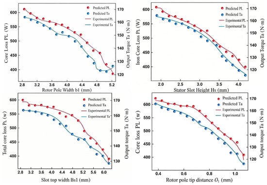
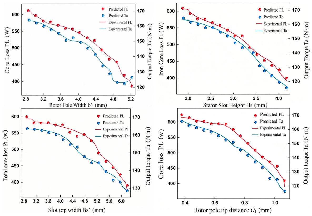
The model fitting curves corresponding to each optimization variable are plotted in Figure 19.
Figure 19.
Comparison between experimental values and neural network fitting values of four key optimization parameters.
It can be observed from the curves that the prediction curves of the BP neural network are basically coincident with the finite-element simulation curves, with no obvious deviation across the entire parameter range, which demonstrates the excellent generalization capability of the proposed model.
To eliminate the reliability risk of the Pareto front caused by the strong nonlinear parameter–performance correlation, three typical non-dominated Pareto-optimal solutions are selected for secondary finite-element simulation verification, including Point 7 (maximum torque), Point 15 (balanced torque-loss performance), and Point 11 (minimum permanent magnet loss). The structural parameters of the three groups of schemes and the comparison between surrogate model predicted values and FEA true values are summarized in Table 11.
Table 11.
Parameters and predicted-FEA performance comparison of three Pareto schemes.
As shown in Table 11, the relative errors of rated torque and permanent magnet peak loss between surrogate model prediction and FEA recalculation are all controlled within 1.3%, which is far lower than the 5% overall error threshold of the BP neural network. Although small parameter variations will lead to obvious fluctuation of torque and loss due to strong electromagnetic coupling, the BP surrogate model can accurately capture this nonlinear changing rule. The FEA verification results prove that the Pareto-optimal front solved by the surrogate model combined with NSGA-II has high reliability, and the prediction deviation will not affect the selection of optimal structural parameters in engineering practice.
Combining the quantitative evaluation metrics and fitting performance, the BP neural network exhibits a significantly stronger capability in fitting the strongly nonlinear electromagnetic characteristics of the motor compared with the second-order response surface model. Accordingly, the BP neural network is selected as the surrogate model for the subsequent multi-objective optimization in this work.
4. Results and Discussion
All electromagnetic performance comparisons before and after optimization are implemented under completely consistent constraint boundaries to guarantee fair evaluation. The armature winding current density of both the initial prototype and optimized scheme is locked at the design limit value of 6.5 A/mm2 without any adjustment of excitation current, and all simulation cases share a unified thermal constraint threshold where the maximum allowable permanent magnet temperature rise is limited to 120 °C, matching the identical heat dissipation structure and cooling condition of the vehicle motor. Meanwhile, a unified rated operating working point of 2600 r/min is adopted throughout the comparison, together with identical winding three-phase excitation, consistent stator and rotor material grades including DW310-35 silicon steel and NdFe35 magnet, as well as unchanged core axial length and stator outer diameter. No relaxation or tightening of current or thermal limits is applied during structural parameter optimization, which means the torque promotion and loss reduction achieved merely stem from the improved air-gap magnetic field distribution through reasonable stator and rotor geometry matching, rather than the alteration of electrical or thermal boundary constraints.
After completing the multi-objective optimization via the NSGA-II algorithm and screening the optimal combination of structural parameters, finite-element simulations are employed to conduct comprehensive comparative verification of the motor before and after optimization. In this section, the internal mechanisms underlying performance variations are elaborated from four perspectives: air-gap magnetic field, torque characteristics, loss characteristics and operating efficiency. Furthermore, the engineering value of the optimized scheme is systematically evaluated based on electromagnetic principles.
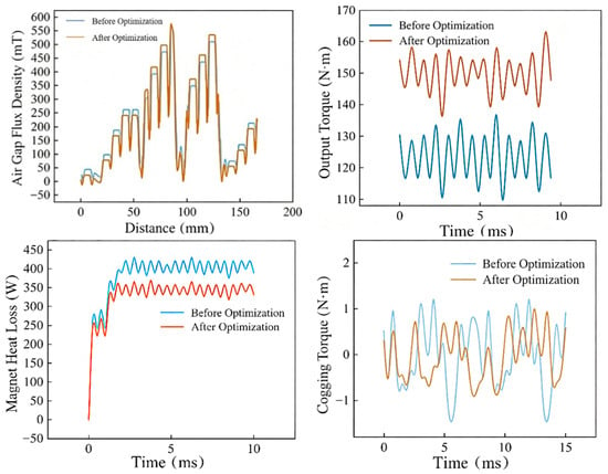
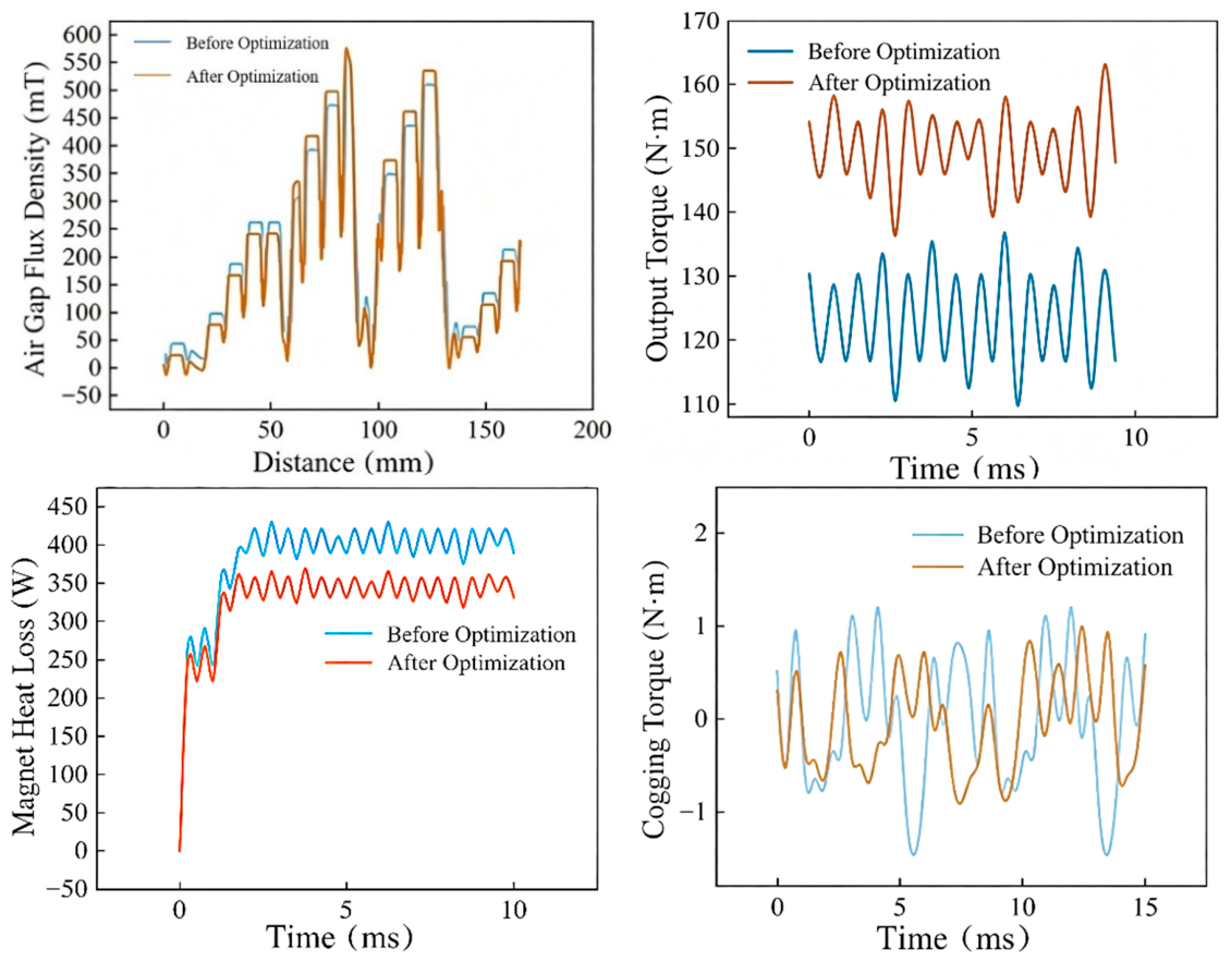
The time-domain waveforms of permanent magnet thermal loss, rated torque, cogging torque and air-gap flux density before and after optimization are illustrated in Figure 20.
Figure 20.
Comparison of four electromagnetic performance indicators before and after optimization.
4.1. Optimization Mechanism of Air-Gap Magnetic Field
The air-gap magnetic field serves as the core medium for electromechanical energy conversion, and its amplitude and waveform distribution directly determine the torque output capacity and loss level of the motor. The sinusoidal property of the optimized air-gap magnetic field waveform is significantly improved through the coordinated regulation of the four core structural parameters. The stator slot opening height Hs0 is increased from 0.80 mm to 0.87 mm, which optimizes the reluctance distribution in the slot opening region and alleviates magnetic circuit contraction at the slot opening. This measure effectively raises the proportion of effective radial air-gap flux, smooths the abrupt change in air-gap permeance, and weakens the tooth harmonics induced by the cogging effect. The rotor pole width B1 is adjusted from 5.00 mm to 4.48 mm to reasonably match the pole arc coefficient and the effective excitation area of magnetic poles, thereby reducing flux leakage at the pole edges. Combined with the uniform transitional reluctance between magnetic poles brought by the increased rotor pole tip distance O1, the edge distortion of the air-gap magnetic field is effectively suppressed. The stator slot top width Bs1 is increased from 4.20 mm to 5.22 mm to optimize the flux density distribution in stator teeth, confine the tooth magnetic load within a reasonable range, and avoid the attenuation of main flux caused by local magnetic saturation. Benefiting from the synergistic effect of these four parameters, the fundamental amplitude of air-gap flux density is boosted while the content of high-order harmonics is reduced, which lays a magnetic field foundation for torque improvement and permanent magnet eddy current loss suppression of the motor.
4.2. Analysis of Rated Torque Enhancement Mechanism
The steady-state output torque of the optimized motor remains stably above 155 N∙m with a peak torque of 170 N∙m, representing a 9.01% improvement compared with the original design. According to the torque generation principle of permanent magnet synchronous motors, the torque increment originates from the increased magnetic load and improved utilization efficiency of the magnetic circuit. Since electromagnetic torque is approximately proportional to the fundamental amplitude of air-gap flux density, the significantly elevated fundamental component enhances the excitation level of the main magnetic circuit and improves the electromechanical energy conversion capacity per unit volume. Meanwhile, the optimized sinusoidal waveform of the air-gap magnetic field strengthens the coupling between winding magnetomotive force and the air-gap magnetic field, reducing invalid flux interaction induced by harmonics and enabling more excitation flux to contribute to effective torque output. Furthermore, the optimized stator slot structural parameters reduce slot leakage flux, allowing armature reaction flux to fully participate in energy conversion within the main magnetic circuit and further enlarge the torque gain. Among all structural parameters, the collaborative adjustment of the stator slot opening height Hs0 and rotor pole tip distance O1 exerts the most prominent effect on torque improvement. By reconstructing the distribution of air-gap permeance and increasing the proportion of main flux, these two parameters fully exploit the excitation potential of the motor.
4.3. Suppression Mechanism of Permanent Magnet Eddy Current Loss
The thermal loss curves of permanent magnets reveal that the average steady-state eddy current loss of the optimized motor decreases from 410 W to 350 W, with the peak loss restricted below 400 W, leading to an overall 16.5% reduction in the peak thermal loss of permanent magnets. Permanent magnet eddy current loss arises from eddy currents induced inside permanent magnets by alternating harmonic magnetic fields, which further generate Joule heat. In this study, structural optimization is adopted to suppress losses at the source of harmonics. The stator slot opening parameters Hs0 and Bs1 smooth the periodic fluctuation of air-gap permeance, weaken tooth harmonics caused by the cogging effect, and significantly reduce the surface eddy current loss of permanent magnets. The collaborative optimization of rotor pole width B1 and pole tip distance O1 improves the spatial magnetic field distribution of magnetic poles and attenuates high-order spatial harmonics such as the third and fifth harmonics, fundamentally cutting down the internal eddy current loss within permanent magnets. Meanwhile, the flux density distribution in stator teeth becomes more uniform, avoiding magnetic field distortion induced by local magnetic saturation and eliminating extra harmonics derived from saturation, which further restrains additional eddy current losses. The reduction in permanent magnet eddy current loss can cut down the heat source generated inside magnets, which is beneficial to mitigate heat accumulation and weaken the potential high-temperature demagnetization tendency during high-speed operation.
4.4. Trade-Off Analysis of Torque Ripple and Cogging Torque
The torque ripple coefficient of the optimized motor reaches 4.23%, which increases slightly compared with the original scheme but still stays below the industry engineering limit of 5%. The peak value of the optimized cogging torque is only 1.463 N∙m, accounting for 1.08% of the rated torque, which is far lower than the design threshold of 2%.
Mechanically, the slight increase in torque ripple can be regarded as a reasonable trade-off during the torque enhancement process. While the fundamental amplitude of air-gap flux density is improved, the amplitudes of low-order harmonics increase slightly. In addition, the interaction between the armature reaction and the permanent magnetic field generates a small amount of reluctance torque ripple after the adjustment of stator slot parameters. Nevertheless, benefiting from the overall improved sinusoidal quality of the air-gap magnetic field, the ripple amplitude is restricted within the allowable engineering range.
The low magnitude of cogging torque is attributed to the optimized matching between slot–pole combination and slot structural parameters. The eight-pole 48-slot topology inherently possesses the advantage of low cogging torque. Combined with the optimized slot opening height and slot top width, the periodic fluctuation of air-gap permeance is further suppressed, which guarantees stable operation of the motor at low speeds.
4.5. Improvement Characteristics of Full-Domain Operating Efficiency
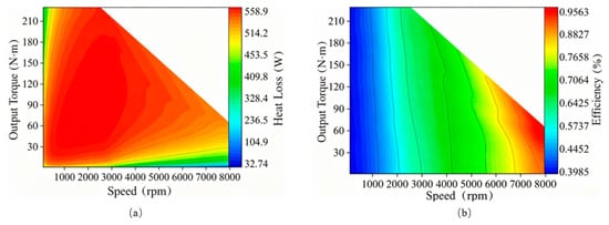
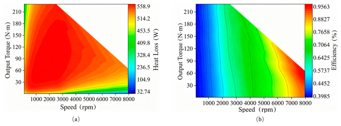
The full-operation efficiency map and permanent magnet loss contour plot of the motor are presented in Figure 21. Figure 8 shows the full-range efficiency and loss contours of the original prototype, which can be intuitively compared with the optimized performance nephograms plotted in Figure 21.
Figure 21.
Contour maps of motor efficiency and permanent magnet loss under full operating speeds after optimization. (a) Permanent magnet heat loss; (b) motor efficiency.
After optimization, the high-efficiency region with efficiency no less than 90% covers the entire speed range from 1000 r/min to 8000 r/min and the full torque range of 30–210 Nm. The maximum efficiency of the optimized motor reaches 97.1%, representing an improvement of 2.5 percentage points over the original design. Under extreme operating conditions, the peak loss of permanent magnets decreases from 694.0 W to 555.3 W, with a reduction rate of 19.98%.
Winding copper loss dominates total losses in the medium- and low-speed operating regions. Benefiting from the enhanced torque output capacity, the armature current required to deliver the same torque is reduced, thereby lowering winding copper loss. Meanwhile, the optimized magnetic circuit stabilizes stator core loss, contributing to a remarkable efficiency improvement within this speed range. As the motor operates at high speeds, the proportions of core loss and permanent magnet eddy current loss increase significantly. The substantial reduction in permanent magnet eddy current loss directly cuts total high-speed losses. In addition, the improved sinusoidal quality of the air-gap magnetic field suppresses core harmonic hysteresis loss and eddy current loss, effectively slowing the efficiency degradation rate under high-speed conditions. The optimized motor achieves a substantially expanded high-efficiency operating range, which satisfies the wide speed regulation requirement of vehicle traction motors, reduces the comprehensive energy consumption of the whole vehicle during driving, and extends the driving range of electric vehicles.
4.6. Synergistic Law of Structural Parameters
The electromagnetic system of the motor is a strongly coupled nonlinear system with multiple parameters, where mutual restrictive trade-offs exist among various performance indicators, making it difficult to achieve simultaneous optimization of all performances. The four optimized parameters selected in this study do not work independently but exert coupled matching effects through the air-gap magnetic field. Specifically, the stator-side parameters Hs0 and Bs1 mainly regulate the air-gap permeance distribution and stator tooth flux density, which predominantly modify slot leakage flux and loss characteristics. By contrast, the rotor-side parameters B1 and O1 dominate the modulation of the amplitude and waveform of the excitation magnetic field, exerting crucial influences on torque output and spatial air-gap harmonics. The coordinated collaboration between stator and rotor parameters boosts the main magnetic flux and output torque while attenuating harmonic magnetic fields and restraining permanent magnet losses. This approach breaks the inherent trade-off between torque and loss and realizes the simultaneous optimization of the two core performances.
Table 12 summarizes the quantitative comparison of key structural dimensions and electromagnetic performances before and after optimization. The original motor suffers from drawbacks including insufficient rated torque and excessive permanent magnet loss. Through multi-parameter collaborative multi-objective optimization, both core performance indicators are significantly improved, which effectively addresses the engineering bottleneck restricting the power density enhancement of the original motor structure.
Table 12.
Comparison of structural parameters and electromagnetic performance before and after optimization.
5. Conclusions
Aiming at the optimization requirement between torque output and permanent magnet loss of high-power-density brushless DC motors for vehicle applications, this paper investigates the influence rules of key structural parameters, the applicability of surrogate models and the performance of multi-objective optimization. The main conclusions are summarized as follows:
- (1)
- There exists an obvious hierarchical difference in the regulation effect of motor structural parameters on torque and loss. Rotor pole width and rotor pole tip distance dominate torque output characteristics by adjusting the excitation capacity of the main magnetic circuit and the waveform of the air-gap magnetic field. Stator slot opening height and slot top width exert a more significant influence on permanent magnet eddy current loss via regulating slot leakage flux and stator tooth flux density. The parameter dimensionality reduction strategy based on sensitivity analysis can reduce the number of design variables while guaranteeing optimization accuracy, which effectively alleviates the low computational efficiency problem in high-dimensional parameter optimization.
- (2)
- For the multi-parameter coupled electromagnetic scenario of the eight-pole 48-slot BLDC motor investigated in this work, the BP neural network possesses stronger fitting capability for strongly nonlinear electromagnetic parameter mapping relationships and achieves higher prediction accuracy compared with the second-order response surface model, which provides reliable surrogate computing support for multi-objective optimization.
- (3)
- The collaborative adjustment of key structural parameters improves air-gap magnetic field distribution and magnetic circuit utilization efficiency, thus realizing the simultaneous improvement of torque promotion and loss suppression. Under the premise that cogging torque, torque ripple and other indicators satisfy the operating constraints of vehicle motors, the optimized design achieves a 9.01% increase in rated torque and a 16.5% reduction in peak thermal loss of permanent magnets, which verifies the effectiveness of the proposed multi-objective optimization strategy.
- (4)
- Structural parameter optimization expands the high-efficiency operating range of the motor and raises the maximum efficiency by 2.5 percentage points. The overall decline in permanent magnet loss reduces internal heat generation of magnets and mitigates the potential high-temperature demagnetization tendency under heavy-duty operation. This research provides a reference for the thermal safety design and high-efficiency operation of high-power-density BLDC motors for electric vehicles.
Author Contributions
Conceptualization, Y.P.; methodology, Y.P. and X.Y.; software, R.L. and Y.Z.; validation, D.Y., X.D., Y.L. and Y.W.; formal analysis, Y.P. and X.Y.; investigation, R.L. and Y.Z.; resources, X.D., Y.L. and Y.W.; data curation, R.L. and Y.Z.; writing—original draft preparation, Y.P.; writing—review and editing, X.Y., D.Y., X.D., Y.L. and Y.W.; visualization, R.L. and Y.Z.; supervision, X.D., Y.L. and Y.W.; project administration, Y.P.; funding acquisition, X.D., Y.L. and Y.W. All authors have read and agreed to the published version of the manuscript.
Funding
Science Foundation of Wuhan Institute of Technology (Project No. K201912).
Data Availability Statement
The datasets used and/or analyzed during the current study are available from the corresponding author on reasonable request.
Acknowledgments
We would like to thank the authors of the references for their enlightenment.
Conflicts of Interest
The authors declare no conflicts of interest. The funders had no role in the design of the study; in the collection, analyses, or interpretation of data; in the writing of the manuscript; or in the decision to publish the results.
Abbreviations
The following abbreviations are used in this manuscript:
| BLDC | Brushless DC |
| NSGA-II | Non-dominated Sorting Genetic Algorithm II |
| RSM | Response surface methodology |
| FEA | Finite-element analysis |
| BBD | Box–Behnken design |
| BP | Back propagation |
| MSE | Mean square error |
References
- Lee, H.J.; Lim, K.S.; Kwon, K. Optimization of multi-motor and multi-speed powertrain system for electric vehicles based on efficiency characteristics between motor and inverter. Energy 2025, 337, 138616. [Google Scholar] [CrossRef] [Scilit]
- Ma, L.; Pan, Y.; Liu, W.; Wang, G.; Mikkola, A. Optimizing suspension parameters for ride comfort in four-wheel hub-motor electric vehicles using multibody dynamics and multi-objective algorithms. Mech. Mach. Theory 2025, 214, 106120. [Google Scholar] [CrossRef] [Scilit]
- Hu, H.; Wu, Y.; Fang, H. Robust optimization of vibration characteristics for permanent magnet DC motors. Measurement 2025, 256, 118024. [Google Scholar] [CrossRef] [Scilit]
- Zhang, R.; An, L.; Yang, X.; He, L.; Huang, Z. A distributed inference method integrating causal analysis and surrogate models for optimizing tuned mass damper parameters to enhance offshore wind turbine safety. Reliab. Eng. Syst. Saf. 2025, 257, 110863. [Google Scholar] [CrossRef] [Scilit]
- Hurtado-Alonso, N.; Manso-Morato, J.; Revilla-Cuesta, V.; Skaf, M. Strength-based RSM optimization of concrete containing coarse recycled concrete aggregate and raw-crushed wind-turbine blade. Compos. Struct. 2025, 356, 118895. [Google Scholar] [CrossRef] [Scilit]
- Megrini, M.; Gaga, A.; Mehdaoui, Y. Processor in the loop implementation of artificial neural network controller for BLDC motor speed control. Results Eng. 2024, 23, 102422. [Google Scholar] [CrossRef] [Scilit]
- Prakash, A.; Naveen, C. Combined strategy for tuning sensor-less brushless DC motor using SEPIC converter to reduce torque ripple. ISA Trans. 2023, 133, 328–344. [Google Scholar] [CrossRef] [Scilit] [PubMed]
- Meo, S.; Zohoori, A.; Vahedi, A. Optimal design of permanent magnet flux switching generator for wind applications via artificial neural network and multi-objective particle swarm optimization hybrid approach. Energy Convers. Manag. 2016, 110, 230–239. [Google Scholar] [CrossRef] [Scilit]
- Chai, X.; Liu, J. Multi-objective optimization of enhanced stator permanent magnet hybrid stepping motor based on Taguchi and respond surface method. Alex. Eng. J. 2025, 133, 564–576. [Google Scholar] [CrossRef] [Scilit]
- Yin, L.; Zhao, B.; Gao, F. Transformer-accelerated multi-objective high-dimensional multi-fractional-order optimization algorithm for proportional-integral controller parameters tuning of doubly-fed induction generators. Swarm Evol. Comput. 2026, 101, 102325. [Google Scholar] [CrossRef] [Scilit]
- Ding, Y.; Liu, G.; Xiang, L.; Ma, S.; Sui, C. Multi-objective optimization of large cruise ship power plant configuration based on NSGA-II algorithm and AHP-entropy weighted TOPSIS-VIKOR. Appl. Ocean Res. 2026, 169, 105007. [Google Scholar] [CrossRef] [Scilit]
- Mohamed, M.Y.; Fawzi, M.; Kalas, A.; Abdel-Khalik, A.S.; Ahmed, S.; Refaat, A. Optimized design of a fault-tolerant 12-slot/10-pole six-phase surface permanent magnet motor with asymmetrical winding configuration for electric vehicles. Alex. Eng. J. 2025, 110, 527–539. [Google Scholar] [CrossRef] [Scilit]
- Najafian, A.; Jahangirian, A. Maximum annual energy production of a 1.5 MW wind turbine using optimum morphing blades at different control management scenarios. Energy Convers. Manag. 2025, 326, 119429. [Google Scholar] [CrossRef] [Scilit]
- Jiang, Y.; Lu, Y.; Chen, L.; Zheng, E.; Wang, C.; Luo, Z.; Shi, Y.; Wang, X.; Hu, L.; Zhao, S. Modeling, analysis, and optimization of the asymmetric cooling system for a hybrid oil-cooled motor. Appl. Therm. Eng. 2025, 270, 126215. [Google Scholar] [CrossRef] [Scilit]
- Wang, J.; Shi, W.; Ren, Y.; Ran, X.; Collu, M.; Venugopal, V.; Zhao, H. An integrated multi-objective optimization framework for large-scale floating offshore wind turbine. Renew. Energy 2026, 258, 124978. [Google Scholar] [CrossRef] [Scilit]
- El Fadli, O.; Hmamed, H.; Lagrioui, A. Multi-objective optimization and improved decision-making in renewable energy investments for enhancing wind turbine selection: Framework and a case study. Energy Convers. Manag. 2025, 326, 119464. [Google Scholar] [CrossRef] [Scilit]
- Pascual, N.; Martínez, Á.; Erro, I.; Astrain, D. Multi-parameter and multi-objective optimisation of thermoelectric modules for enhanced performance in geothermal passive generators. Energy Convers. Manag. 2026, 351, 120991. [Google Scholar] [CrossRef] [Scilit]
- Le Pivert, F.; Roberts, A.; López-Santander, A.; Craven, M.J.; Kazemi, S. Data driven multi-objective optimization of the scheduling for towing a floating offshore wind turbine between assembly port and installation location throughout a year. Appl. Ocean Res. 2025, 157, 104492. [Google Scholar] [CrossRef] [Scilit]
- Luo, Z.; Xu, R.; Zhang, J.; Zhang, T.; Liu, X.; Liu, X. Thermal energy storage optimization in fully PV-powered airports: Capacity configuration and multi-objective strategy. J. Energy Storage 2026, 141, 119274. [Google Scholar] [CrossRef] [Scilit]
- Chen, S.; Xu, P.; Liu, Y. Design and multi-objective optimization of hairpin motor cooling system based on orthogonal design method and composite algorithm. Appl. Therm. Eng. 2025, 259, 124971. [Google Scholar] [CrossRef] [Scilit]
- Sun, J.; Yang, J.; Jiang, Z.; Xu, J.; Meng, X.; Feng, X.; Si, Y.; Zhang, D. Wake redirection control for offshore wind farm power and fatigue multi-objective optimisation based on a wind turbine load indicator. Energy 2024, 313, 133893. [Google Scholar] [CrossRef] [Scilit]
- Garmut, M.; Steentjes, S.; Petrun, M. Computationally efficient multi-objective optimization of an interior permanent magnet synchronous machine using neural networks. Eng. Appl. Artif. Intell. 2025, 160, 111753. [Google Scholar] [CrossRef] [Scilit]
- Li, J.; Zuo, Z.; Ma, Y.; Jia, B.; Wei, Y.; Lin, H.; Feng, H.; Liu, C.; Wei, S. Multi-objective optimization of linear generator based on global sensitivity analysis for enhanced linear range extender performance. Energy 2025, 326, 136218. [Google Scholar] [CrossRef] [Scilit]
- Zhao, R.; Zhu, N.; Zhao, X.; Luo, Z.; Chang, J. Multi-objective optimization of a novel photovoltaic-thermoelectric generator system based on hybrid enhanced algorithm. Energy 2025, 319, 135046. [Google Scholar] [CrossRef] [Scilit]
- Wang, C.; Dong, T.; Chen, L.; Zhu, G.; Chen, Y. Multi-objective optimization approach for permanent magnet machine via improved soft actor–critic based on deep reinforcement learning. Expert Syst. Appl. 2025, 264, 125834. [Google Scholar] [CrossRef] [Scilit]
- Rojas-López, A.G.; Villarreal-Cervantes, M.G.; Rodríguez-Molina, A. Surrogate indirect adaptive controller tuning based on polynomial response surface method and bioinspired optimization: Application to the brushless direct current motor controller. Expert Syst. Appl. 2024, 245, 123070. [Google Scholar] [CrossRef] [Scilit]
- Lei, B.; Fei, S. Adaptive fuzzy coordinated control design for wind turbine using gray wolf optimization algorithm. Appl. Soft Comput. 2024, 167, 112319. [Google Scholar] [CrossRef] [Scilit]
- Demirtas, M. Off-line tuning of a PI speed controller for a permanent magnet brushless DC motor using DSP. Energy Convers. Manag. 2011, 52, 264–273. [Google Scholar] [CrossRef] [Scilit]
- Li, H.; Wang, B. Hybrid wind turbine and natural gas-driven multi-generation system: 4E analysis and multi-objective optimization for efficient waste heat recovery in a compressed air energy storage system. Energy 2026, 344, 139778. [Google Scholar] [CrossRef] [Scilit]
- Cheng, Y.; Liu, J.; Qi, H.; Zhao, Y.; Zhou, X. Generative design of steel-prestressed concrete hybrid wind turbine tower based on machine learning and multi-objective optimization. Eng. Struct. 2025, 341, 120835. [Google Scholar] [CrossRef] [Scilit]

Disclaimer/Publisher’s Note: The statements, opinions and data contained in all publications are solely those of the individual author(s) and contributor(s) and not of MDPI and/or the editor(s). MDPI and/or the editor(s) disclaim responsibility for any injury to people or property resulting from any ideas, methods, instructions or products referred to in the content. |
© 2026 by the authors. Licensee MDPI, Basel, Switzerland. This article is an open access article distributed under the terms and conditions of the Creative Commons Attribution (CC BY) license.