


Abstract
Torque-limiting mechanisms are safety-critical elements in mechanical, automotive, robotic, aerospace and medical systems, where controlled torque transmission is required to avoid overload failure. However, the influence of dent–slot geometry on torque stability, variability and tolerance sensitivity remains insufficiently quantified. This study examines the effects of dent height, dent angle and spring plate thickness on the torque response of a compact elastic, shape-dependent torque-limiting mechanism. An integrated methodology comprising conceptual design, mathematical modelling, theoretical analysis, finite element analysis, manufacturability assessment, material characterisation, dynamic testing and VIKOR-based decision-making was implemented. Five feasible spring-drive plate configurations were investigated using two dent heights, two dent angles and two spring plate thicknesses. Material and interface properties for the Ck67–SINT D39 tribological pair were determined through tensile, flexural and friction tests, while dynamic torque and output-force data were obtained using a dedicated test bench and statistically evaluated after Chauvenet-based removal of isolated peak values. The mathematical, theoretical, numerical and experimental results showed close agreement, with torque deviations below approximately 1.5% for the main comparison metrics. Increasing dent height from 1.40 to 1.80 mm reduced relative torque variability by 34.6%, whereas reducing the dent angle from 110° to 90° increased relative torque variability by 95.0%. Configuration A2 provided the best balance, confirming dent geometry as a controllable design variable.
1. Introduction
Torque-limiting mechanisms constitute a fundamental class of safety components in modern mechanical systems, serving the critical function of preventing overload-induced failures by restricting or interrupting torque transmission when predefined threshold values are exceeded [1,2,3]. The operational principle underlying these mechanisms involves either the controlled dissipation of excess energy through frictional slip or the complete mechanical disconnection of the driving and driven elements upon the detection of an overload condition [4,5]. Their application domains span a remarkably diverse spectrum, encompassing conventional material handling systems such as conveyor belts and industrial agitators, as well as high-precision and safety-critical sectors including aerospace actuation systems, automotive powertrain and driveline components, collaborative and service robotics, and advanced medical and surgical devices [6,7,8]. Depending on the specific operational context, reliability expectations, and economic constraints, torque-limiting systems may be designed according to either destructive–disposable principles, wherein a sacrificial element such as a shear pin is designed to fail at a predetermined load, or non-destructive–repeatable principles, wherein the mechanism is capable of resetting and resuming normal operation following the clearance of the overload event [6,9].
The technological landscape of torque-limiting solutions encompasses a broad array of mechanical, magnetic, and electronically controlled implementations. Representative mechanical configurations include friction plate systems, slip clutches, ratchet-and-pawl assemblies, ball or roller detent mechanisms, and shear pin devices [10,11,12]. Friction-based torque limiters, in particular, employ spring-loaded friction disks that act upon one another in a manner analogous to an automotive clutch, whereby the adjustment of spring preload determines the torque slip threshold [3,13]. Ball or roller release detent limiters rely on spring-loaded rolling elements that engage with mating detents; when the applied torque generates forces sufficient to overcome the spring preload, the rolling elements disengage, interrupting torque transmission [14]. In parallel, advanced solutions incorporating magnetic particle systems, magnetorheological fluids, magnetic hysteresis devices, and eddy-current-based limiters have been developed for applications demanding contactless operation or continuously variable torque thresholds [15,16]. Electronically controlled torque-limiting systems offer programmable torque profiles and adaptive threshold adjustment, albeit at the cost of increased system complexity and potential latency in overload response [13,17].
Despite the wide variety of available torque-limiting technologies, mechanical implementations retain compelling advantages for applications where compactness, lightweight construction, cost-effectiveness, and inherent fail-safe operation are paramount [2]. Mechanical torque limiters provide overload protection within milliseconds, considerably faster than electrical sensing and actuation counterparts, and achieve this without reliance on external power sources or complex control electronics. Within this category, a wide variety of spring configurations, including helical coil springs, planar spiral springs, leaf springs, diaphragm springs, and Belleville disc springs, have been employed to provide the requisite restoring forces and to govern engagement–disengagement dynamics. The performance and reliability of such mechanisms are governed by a complex interplay of material properties, heat treatment regimes, frictional behaviour, wear progression, and the accumulation of manufacturing and assembly tolerances.
The closest related studies have primarily focused on generating or adjusting a prescribed mechanical release threshold. Lee et al. [18] developed a passive Spring-Clutch torque limiter comprising a coil spring and a CAM mechanism. The mechanism behaves as a rigid connection below a preset threshold torque but permits relative angular displacement between the input and output when this threshold is exceeded. Park and Song [19] subsequently investigated a nonlinear-stiffness safe joint for collision protection. Choi et al. [1] subsequently introduced a variable-threshold Spring-Clutch in which spring deflection was mechanically adjusted to control the release torque. For detent-type torque limiters, Ahmad et al. [3] showed analytically that transmitted torque depends on the groove profile, normal force, number of contact elements, and effective radius. The research scope, parameterisation, methodology, and principal findings of these studies are compared in Table 1.
Table 1.
Comparison of closely related passive torque-limiting mechanisms and the present study.
Collectively, these studies demonstrate that mechanical geometry and elastic loading can be used to define or adjust the release threshold of passive torque-limiting and safety-joint mechanisms. However, they did not systematically quantify how controlled variations in dent/slot geometry and elastic-member thickness affect both limiting-torque level and repeat-cycle variability, nor did they relate these effects to production-relevant geometric tolerances. The present study addresses this gap by investigating dent height, dent angle, and spring-plate thickness within a common manufacturable architecture.
A further dimension of complexity concerns the management of manufacturing tolerances and their propagation through the system. Tolerance analysis quantifies the impact of dimensional variations on functional behaviour and quality level [20]. When multiple conflicting performance criteria must be simultaneously considered, the problem is most appropriately formulated as a multi-criteria decision-making (MCDM) task. The VIKOR method has emerged as a powerful MCDM tool for identifying a compromise solution closest to the ideal alternative and farthest from the worst-case scenario [21]. VIKOR has been successfully applied in material selection, automotive body structure optimisation, and compliant mechanism design [22].
Accordingly, the primary objective of this study is to systematically investigate the effect of geometric parameters, dent height, dent angle, and spring plate thickness, on the torque response, stability, and variability of a novel elastic, shape-dependent torque-limiting mechanism. A secondary objective is to establish a rigorously validated, integrated multidisciplinary framework encompassing conceptual design, mathematical modelling, theoretical analysis, finite element analysis, manufacturability assessment, material characterisation, experimental validation, and multi-criteria decision-making. The proposed mechanism, as illustrated schematically (Figure 2), comprises a spring plate featuring dented geometric features and a drive plate containing corresponding slots, both mounted on a central spindle. The geometry of the dent features, together with material thickness, is hypothesised to govern both nominal torque response and output force. Based on prior insights, it is further hypothesised that maintaining strict control over manufacturing tolerances and geometric consistency is essential for achieving stable and predictable performance.
Component-level testing and integrated experimental–numerical approaches have proven essential for understanding such interactions and validating mechanical system performance [23,24,25]. Against these literature benchmarks, this study makes three specific contributions. First, it quantitatively evaluates dent height, dent angle, and spring-plate thickness as design variables governing torque response and variability, showing that increasing dent height reduces relative torque variability from 4.31% (A1) to 2.82% (A2), while reducing dent angle from 110° to 90° increases variability from 2.82% (A2) to 5.50% (A3). Second, it quantifies the sensitivity of torque to production-relevant geometric tolerances. Third, it establishes a traceable validation chain combining analytical modelling, FEA, manufacturability assessment, material characterisation, and dynamic testing across five feasible configurations.
2. Materials and Methods
2.1. Study Design and Integrated Engineering Framework
The methodological foundation of the present study was established upon a systematic and integrated multidisciplinary workflow encompassing conceptual design, theoretical analysis, mathematical modelling, material characterisation, numerical simulation, manufacturability assessment, process control, experimental validation, and multi-criteria decision-making. This comprehensive framework was deliberately constructed to ensure the generation of robust, technically valid, and industrially relevant results by establishing explicit and traceable connections among all phases of the design and validation process. The overall sequence and logical interdependencies of the study are illustrated schematically in Figure 1. The figure emphasises the integrated framework, which constitutes the core of the methodology, by tracing the logical flow from design inputs to experimental validation and decision-making.
Figure 1.
Integrated multidisciplinary design, optimisation, and validation framework.
Within this overarching framework, the initial phase of the investigation was dedicated to establishing the technical rationale for the proposed torque-limiting mechanism, critically examining the strengths and limitations of related systems documented in the literature, and defining the principal objectives and design variables that would govern the subsequent parametric study. In order to ensure that the technical requirements, metric design inputs, and validation conditions were firmly grounded in a realistic and industrially relevant engineering context, a representative use case was selected. Specifically, a spare-wheel winch system, a component widely deployed in light and medium commercial vehicles within the automotive sector, was adopted as the reference application and adapted to the design requirements of the proposed elastic, shape-dependent torque-limiting mechanism.
The spare-wheel winch constitutes a safety-critical subsystem that performs the dual function of permitting wheel replacement when required and securely retaining the spare wheel in its stowed position during vehicle service, including under severe loading conditions such as impact events and prolonged exposure to road-induced vibration. Stable clamping torque, and consequently stable clamping force, are therefore essential performance attributes to prevent loosening or complete loss of the spare wheel under dynamic service conditions. The loosening behaviour and progressive loss of clamp force in such a system are strongly analogous to the well-documented phenomena observed in conventional bolted joints [26,27]. On this basis, the technical requirements and metric design inputs for the torque-limiting mechanism were derived from a comprehensive review of applicable regulations, international norms and standards, and vehicle-manufacturer engineering specifications, together with functional and compactness-related geometric constraints.
In the detailed execution of the framework, a design-for-manufacture-oriented theoretical model and a fail-safe conceptual design were developed in parallel using the SolidWorks computer-aided design environment (Version 2021 SP5, Dassault Systèmes, Waltham, MA, USA). This development was conducted concurrently with the formulation of the mathematical model, the execution of theoretical calculations, and the establishment of initial material property assumptions. In order to enable meaningful and statistically valid comparisons among the outputs of the mathematical modelling, theoretical analysis, finite element analysis (FEA), and experimental testing phases, stringent yet manufacturable tolerances, consistent with the capabilities and limitations of the intended production processes, were incorporated at both the component and mechanism levels to mitigate process-induced variability. Based on the conceptual design, an experimental programme comprising five distinct geometric configurations was prepared, as detailed in Section 2.3.
Iterative manufacturability assessments and FEA were subsequently carried out using the AutoForm sheet metal forming simulation code (Version R12, AutoForm Engineering GmbH, Pfäffikon, Switzerland) and the ANSYS Workbench FEA platform (Version 2024 R2, ANSYS Inc., Canonsburg, PA, USA), respectively. In parallel, the necessary process tooling, assembly fixtures, and test-bench adaptations were designed and manufactured specifically to meet the requirements of the present study. Material characterisation was undertaken through a comprehensive suite of experimental tests, including flat-surface and inclined-surface friction tests, tensile testing, and flexural testing, in order to determine the static and kinetic coefficients of friction, the mechanical properties of the materials, and the stiffness values of the spring plate configurations.
All manufacturing processes, including laser cutting, forming, wire electrical discharge machining (EDM) for contouring, atmosphere-controlled heat treatment, and final assembly, were executed under conditions that were representative of series production, with the explicit objective of minimising process-induced variation. Static measurements and dimensional inspections were conducted both prior to and following each manufacturing stage in order to identify and quantify any dimensional deviations that might influence subsequent performance. Dynamic performance tests were subsequently performed on an adapted test bench, and the Chauvenet criterion was applied for the normalisation and outlier filtering of the experimental data [27,28].
A diverse range of simulation, sampling, optimisation, and decision-making methodologies has been reported in the contemporary engineering literature. In the present study, however, the design space was intentionally constrained and discrete in nature, consisting of five feasible and manufacturable configurations. At the same time, several conflicting performance criteria were required to be considered simultaneously, including nominal torque capacity, worst-case torque bandwidth, the individual tolerance contributions of dent height, dent angle, and spring plate thickness, and the upper torque limit imposed by safety considerations. For these reasons, the design selection problem was most appropriately formulated as a multi-criteria decision-making (MCDM) task rather than as a continuous global numerical optimisation problem.
The VIKOR method was selected as the primary and binding ranking methodology for this study. This choice was predicated on the method’s demonstrated suitability for problems involving discrete alternatives and conflicting criteria, as well as its capacity to identify a compromise solution that is closest to the ideal alternative and farthest from the worst-case scenario [21]. This capability is particularly valuable for tolerance-sensitive mechanical systems, as the VIKOR procedure yields an explicit ranking of the candidate configurations through the computation of a compromise index (Qᵢ), wherein the configuration associated with the lowest Qᵢ value is identified as the most balanced and robust alternative. Finally, all results were assessed using the Minitab statistical software package (Version 14.13, Minitab LLC, State College, PA, USA), a dual-level mean–upper-bound consistency verification procedure, a robustness pre-assessment based on worst-case tolerance propagation, and the VIKOR methodology.
2.2. Design Inputs and Conceptual Design
The conceptual design of the torque-limiting mechanism was developed with the explicit intention of achieving a universal, system-independent architecture that would support broad applicability, ease of serviceability, and straightforward integration into a variety of mechanical systems. On this basis, the technical requirements and design inputs were defined in accordance with vehicle manufacturers’ engineering specifications, which themselves derive from a hierarchy of international regulations, standards, and norms. The specific documents consulted included the International Automotive Task Force Automotive Quality Management System standard (IATF 16949:2016 [29]), the Automotive Industry Action Group Advanced Product Quality Planning manual (AIAG APQP, 2nd Edition: 2008), and safety regulations including Federal Motor Vehicle Safety Standard No. 208 [30], Federal Motor Vehicle Safety Standard No. 214 [31], UN Regulation No. 94 [32], UN Regulation No. 95 [33], and UN Regulation No. 136 [34].
In addition to these regulatory and normative documents, functional and compactness-related geometric constraints, including geometric dimensioning and tolerancing requirements, datum feature definitions, and assembly specifications in accordance with ISO 1101:2017 [35], ISO 5459:2011 [36], and ISO 10579:2010 [37], were incorporated into the design definition. Based on this comprehensive compilation of requirements, the target maximum torque limit for the elastic, shape-dependent mechanism was defined as 50 Nm, and the minimum output force was specified as 600 N. These target values were derived directly from the engineering specifications established from the aforementioned regulations, safety constraints, norms, and standards relevant to the spare-wheel winch systems utilised by vehicle manufacturers.
The conceptual design of the proposed mechanism is illustrated schematically in Figure 2. The mechanism consists of two principal functional components: an elastic spring plate containing integrally formed dent features, and a rigid drive plate containing corresponding slots that engage with the dents of the spring plate. Both components are mounted on a central spindle, which also serves as the means of transmitting motion from the driving source to the driven system. The spring plate material selected for this application was Ck67, a formable, cold-rolled, unalloyed carbon steel that offers a favourable combination of mechanical strength, formability for the creation of the dent features, and suitability for heat treatment to achieve the required hardness and spring properties. The drive plate was manufactured from SINT D39, an iron–bronze–graphite sintered material that is widely employed in high-performance torque-transmission components owing to its excellent tribological properties, self-lubricating characteristics imparted by the graphite content, and good dimensional stability. In Figure 2, the raised features on the spring plate are referred to as ‘dents’, while the corresponding recesses on the drive plate are referred to as ‘slots’.
Figure 2.
Conceptual configuration of the proposed elastic torque-limiting mechanism: spring plate section and dent detail; spring plate front view; assembled mechanism; and dent–slot engagement interface.
2.3. Experimental Design
The experimental design phase of the investigation was focused specifically on the dented region of the spring plate, as this region constitutes the primary functional interface at which torque transmission and limiting behaviour are governed. The objective of the experimental design was to determine, in a systematic and controlled manner, the influence of the geometric parameters of the dent features on the resulting torque response and reliability of the mechanism.
Three principal geometric variables were selected for investigation: dent height (hd), spring plate thickness (t), and dent angle (β). For each variable, two discrete levels were selected in order to satisfy the competing requirements of compactness, structural simplicity, manufacturability, and geometric feasibility within the constraints of the forming process. Specifically, the selected levels were as follows: two dent heights, 1.40 mm and 1.80 mm; two spring plate thicknesses, 0.80 mm and 1.20 mm; and two dent angles, 110° and 90°. All configurations were standardised to a target hardness of 550 HV for the Ck67 spring plate material. This hardness value was selected based on a review of the relevant literature and an analysis of the intended service conditions, with the objective of minimising wear and ensuring consistent elastic behaviour over the operating life of the mechanism.
The selected parameter values represent the investigated lower and upper levels within the manufacturability and compactness constraints of the mechanism. The experimental matrix was intentionally constrained and was not intended to constitute a full factorial design. The five configurations shown in Table 2 were selected to enable controlled pairwise comparisons: A1–A2 for dent height, A2–A3 for dent angle, and A1–B1 and A2–B2 for spring plate thickness. Accordingly, the study evaluates the effects observable from these direct comparisons, whereas complete estimation of the interaction effects would require a full factorial experimental design and remains outside the scope of the present study.
Table 2.
Experimental design configurations (all samples were heat-treated to a target hardness of 550 HV).
The study therefore comprised five geometric configurations, designated A1, A2, A3, B1, and B2. Their nominal geometric parameters are presented in Table 2.
In preparation for the statistical analysis of the dynamic performance test data, a procedure for the identification and exclusion of outliers was established. The Chauvenet criterion was adopted for this purpose, following its documented application across a range of scientific and engineering disciplines [27,28]. The application of the Chauvenet criterion to the 3600 individual measurements acquired across the five configurations resulted in the exclusion of 15 isolated instantaneous peak values, corresponding to approximately 0.42% of the total dataset. Following the removal of these outliers, the standard deviation (σ) and relative variability (RV%) were subsequently calculated for each configuration using the Minitab statistical software package.
2.4. Design Optimisation and Verification
2.4.1. Mathematical Modelling and Theoretical Formulation
The nominal torque capacity and torque variability of the proposed elastic, shape-dependent, compact torque-limiting mechanism were modelled based on the force equilibrium conditions at the interface between the spring plate dent and the drive plate slot, with the inclusion of Coulomb friction. The system was treated as quasi-static, with constant static and kinetic coefficients of friction and linearly elastic material behaviour assumed during the critical phase of dent disengagement. At the instant of incipient disengagement, the force components induced by the applied drive torque are balanced by the restoring force generated by the elastic deformation of the spring plate and the frictional resistance developed at the contact interface.
The model is intended to predict the nominal release torque and its geometric sensitivity under the low-speed operating condition investigated herein; it is not a transient dynamic model of the disengagement event. Inertial effects, impact dynamics, and velocity-dependent friction (including Stribeck and stick-slip effects) are therefore not explicitly represented. The quasi-static assumption is appropriate for the low-speed (15 rpm) condition of this study, where rate-dependent friction effects are minimal. Torque stability is evaluated independently from the cycle-to-cycle dispersion measured in the dynamic tests. The adoption of the Amontons–Coulomb friction model is considered appropriate for this analysis, as the fundamental proportional relationship between frictional force and normal load remains the cornerstone of classical friction modelling [38,39]. Critically, the coefficients of friction and stiffness parameters employed in the analytical model were not assumed a priori, but were instead determined experimentally through a dedicated programme of material characterisation, as detailed below. The tensile testing, flexural testing, and plane-surface friction testing configurations employed for material characterisation are illustrated in Figure 3, while the dent–slot geometry and the associated force system used in the analytical formulation are depicted schematically in Figure 4.
Figure 3.
Material characterisation and mechanical testing procedures, including tensile-strength tests before and after heat treatment for CK67 steel (0.80 and 1.20 mm), spring plate flexural stiffness tests, and flat/inclined surface friction tests for determination of the spring plate–drive plate friction behaviour.
Figure 4.
Geometric and force representation of the dent−slot interaction: (a) definition of dent height (h~d~), dent angle (β) and slot geometry; plate thickness (t) is defined in Section 2.5 and listed in Table 5; and (b) decomposition of the torque-transmission and reaction-force components at the contact point.
The mechanical properties of the Ck67 sheet material were obtained from tensile tests conducted on specimens of both 0.80 mm and 1.20 mm thickness, ensuring that the input properties for the finite element analysis corresponded accurately to the actual material condition in each configuration. The force–deflection behaviour of the spring plate was determined through flexural testing using a custom-designed four-point bending fixture mounted on a Zwick-Roell Z100 universal testing machine. Tests were conducted under displacement control at a constant crosshead speed of 4.0 mm·min−1, with a total applied deflection of 2.0 mm. To mitigate potential end effects and to ensure that the measured stiffness was representative of the linear elastic regime of the dent structure, the initial and final 10% of the deflection interval were excluded from the analysis, and the stiffness was evaluated over the central 10–90% range, taking into account the end radii and bottom radius of the dent geometry illustrated in Figure 4.
The spring stiffness, kSP for each configuration was calculated using Equation (1) from the measured forces F1 and F2 and the corresponding deflections X1 and X2 within the linear evaluation range:
The resulting stiffness values, determined from the flexural tests, were 1183.04 N·mm−1 for configuration A1, 961.81 N·mm−1 for A2, 1031.25 N·mm−1 for A3, 1589.29 N·mm−1 for B1, and 1684.03 N·mm−1 for B2.
In order to characterise the tribological interface between the spring plate and drive plate materials, surface roughness measurements were performed on both the drive plate and a specially prepared 115 g specimen disc manufactured from the SINT D39 material. The arithmetic mean roughness (Ra) and the mean peak-to-valley height (Rz) were measured at four circumferential positions separated by 90° intervals. The results of these measurements are reported in Table 3. The mean Ra values were determined to be 1.59 µm for the drive plate and 1.51 µm for the specimen disc, confirming that the specimen disc constituted an appropriate tribological surrogate for the drive plate surface in the friction tests.
Table 3.
Surface roughness comparison between the drive plate and specimen disc.
To determine the static and kinetic coefficients of friction, both inclined-surface sliding tests and flat-surface friction tests were conducted using the SINT D39 specimen disc in contact with the Ck67 steel plate. The corresponding measurements are listed in Table 4. The mean static coefficient of friction obtained from the inclined-surface test was 0.57, whereas that obtained from the flat-surface test was 0.59, demonstrating close agreement between the two independent measurement methods. Based on these experimental results, the values adopted in the analytical model were a static coefficient of friction μs = 0.58 and a kinetic coefficient of friction μk = 0.20.
Table 4.
Static and kinetic friction coefficient measurements on inclined and flat surfaces.
The theoretical formulation of the torque-limiting mechanism was based on the satisfaction of two fundamental conditions of static equilibrium. The first condition, expressed in Equation (2), represents the equilibrium of the force components acting along the Z-axis on the spring plate dent:
In this expression, FTz is the Z-component of the driving force generated by the applied torque TT, while FSPz, FSWz, and FFz are the corresponding Z-components of the spring restoring force, the counterweight force (derived from the spare-wheel mass), and the friction force, respectively. The friction relation employed in the Z-direction is given by Equation (3):
where α is the inclination angle of the dent flank relative to the horizontal plane (note that α = β/2, where β is the total included dent angle), kSP is the experimentally determined spring stiffness, hdeff is the effective dent deflection, g is the gravitational acceleration, mSW is the mass of the spare wheel, and i1 and i2 are the effective radius ratios relating the spring plate to the winch drum and the transmission system, respectively.
The second equilibrium relation, Equation (4), represents the force balance of the resultant forces acting on the spring plate dent:
The relationship between the resultant forces and their respective Z-axis components is defined by Equation (5):
where Ψ is the angle between the resultant force vectors and their respective projections onto the XZ-plane. The relation between the applied drive torque and the Z-component of the driving force is given in Equation (6):
where ηm is the overall mechanism efficiency (accounting for mechanical losses such that ηm < 1, thereby requiring a higher input torque to achieve the same output) and rSP is the effective radius of the spring plate at the dent location. The output force acting on the counterweight, which is derived from the torque transmitted through the mechanism, is then calculated using Equation (7):
where denotes the cable efficiency of the winch system, and where FTx, FSPx and FSWx are the corresponding X-direction force components transmitted through the winch mechanism.
The mathematical model itself is formally defined in Equation (8):
In this expression, rSP is the lever-arm radius at the spring plate, kSP is the configuration-dependent stiffness obtained from flexural testing, and δ0(hd) is the locking deflection constant derived from the computer-aided design (CAD) geometry. Specifically, δ0 was measured in the CAD model as the vertical displacement of the dent tip when the mating spring plate and drive plate are in the fully engaged position. Based on this CAD analysis, the value of δ0 was determined to be 0.264 mm for hd = 1.40 mm and 0.34 mm for hd = 1.80 mm. The term Φ (θc, μk) is a dimensionless function representing the combined effects of the contact geometry and the kinetic coefficient of friction.
The effective contact angle, θc, was defined using the root-mean-square formulation presented in Equation (9):
where β is the dent angle, and γ is the inclination of the drive plate slot surface. For the present design, the drive plate slot walls are vertical; therefore, γ = 0°.
The combined effect of geometry and friction is expressed in Equation (10):
Since the torque-limiting event involves relative sliding between the dent and slot surfaces, the kinetic friction coefficient μk governs the post-slip behaviour and is therefore employed in this formulation.
The degree of agreement between the mathematical model predictions and the corresponding theoretical and experimental torque values was quantified using the percentage deviation expressions given in Equation (11):
where Tx is the theoretically calculated torque, and Ex is the experimentally measured mean torque.
The theoretical torque Tx is derived from the same mathematical model (Equation (8)) under idealised conditions, i.e., neglecting friction (μk = 0) and secondary effects, to serve as a lower-bound reference for comparison with the experimental results.
2.4.2. Tolerance Analysis and Sensitivity Assessment
In order to quantify the influence of dimensional tolerances on the torque behaviour of the mechanism, a comprehensive tolerance analysis study was performed using the mathematical model described in Section 2.4.1. The objectives of this analysis were threefold: to determine the absolute torque deviation (ΔT) attributable to each individual tolerance; to determine the relative torque deviation (%ΔT) normalised with respect to the corresponding upper-bound torque; and to establish the ranking of parameter criticality across the three input variables: spring plate thickness (t), dent height (hd), and dent angle (β).
The tolerances applied in this analysis were derived from the capabilities of the intended manufacturing processes and the requirements of the relevant international standards. Specifically, the tolerances were Δt = ±0.02 mm for the nominal thickness of 0.80 mm, Δt = ±0.03 mm for the nominal thickness of 1.20 mm (in accordance with EN 10140 T2), Δhd = ±0.10 mm, and Δβ = ±2°. At the nominal operating point, the local sensitivities of the torque to variations in thickness, dent height, and dent angle were evaluated using Equations (12)–(14):
For the purpose of this analysis, a linear relationship between δ0 and hd was assumed within the small tolerance range, such that Δδ0 ≈ (0.34 − 0.264)/(1.80 − 1.40) × Δhd = 0.19 × Δhd.
A worst-case tolerance propagation was adopted to ensure conservative safety margins. The worst-case torque extremes were subsequently calculated by simultaneously applying the tolerance extremes, as expressed in Equations (15) and (16):
To isolate the nominal effect of each geometric variable independently of the others, one-at-a-time configuration pairs were defined such that only a single parameter varied while the remaining parameters were held constant. For each such pair, the absolute change in torque level (ΔT), the proportional change (RT), and the percentage change (%ΔT) were calculated using Equation (17):
The normalised contribution ratios for torque level and torque variability were expressed by Equation (18):
A logarithmic elasticity measure was additionally introduced, as defined in Equation (19), to estimate the percentage change in torque generated by a 1% nominal change in the geometric parameter:
For the angular variable β, this logarithmic elasticity was treated as a supporting indicator, whereas the metrics ΔT, RT, %ΔT, wT > (β), and wV(β) were retained as the primary decision criteria.
To link manufacturing variation with the measured torque dispersion, the observed dent-height and dent-angle deviations in Table 4 were propagated through the local sensitivity model. Thickness variation was represented by the specified manufacturing tolerance. The resulting geometric contribution was combined by root-sum-square propagation. Friction variability was estimated from the measured kinetic-friction coefficient dispersion, while the torque-transducer accuracy (±0.1 Nm) was used to estimate the measurement contribution. The remaining unexplained variance was treated as a residual contribution including unmodelled interface and dynamic effects.
2.4.3. Multi-Criteria Decision-Making Using the VIKOR Method
The criteria for the VIKOR analysis were defined directly from the outcomes of the tolerance analysis and the experimental measurements. The complete set of criteria included the nominal torque (Tm), the worst-case torque band (Tmax, Tmin), the individual tolerance contributions of thickness, dent height, and dent angle (ΔTt, ΔThd, ΔTβ), and the maximum torque value as a safety constraint. In addition to these analytically derived criteria, three experimental performance indicators were defined in Equation (20):
where EB represents the absolute variability bandwidth (the range from the mean to the upper six-sigma bound, which simplifies to 6σ), RV represents the relative variability (the ratio of the standard deviation to the upper six-sigma bound), and ΔM represents the absolute deviation between the mathematical model prediction and the experimental mean.
The normalised distance for each criterion was calculated using Equation (21):
The weighting scheme adopted for the VIKOR analysis was designed to encode the prioritisation of the performance objectives. Stability of torque response was assigned the highest priority, followed by absolute variability control, with model–experiment agreement assigned a tertiary weighting. This prioritisation is reflected in the weight vector defined by Equation (22). The weighting scheme prioritises torque stability as the primary performance objective, followed by absolute variability control and model-experiment agreement, because the central aim of this study is to quantify geometry-driven torque stability. Torque capacity was predefined as a fixed design input (50 Nm), and all configurations satisfied this safety constraint; therefore, it does not serve as a discriminating criterion. Manufacturing cost and fatigue life, while practically relevant, are outside the scope of this parametric investigation and are suggested as future work
where v is the VIKOR parameter that determines the balance between the group utility and the individual regret. The standard value of v = 0.5 was selected to achieve an equal balance between these two aspects.
Finally, the group utility (Si), individual regret (Ri), and the VIKOR compromise index (Qi) for each configuration were computed using Equation (23):
where S* = min Si, S− = max Si, R* = min Ri and R− = max Ri. The configuration yielding the lowest value of the compromise index Qi is identified as the optimal compromise solution.
2.4.4. Finite Element Analysis and Manufacturability Assessment
Manufacturability analysis of the spring plate forming process was performed using the AutoForm sheet metal forming simulation software (AutoForm Engineering GmbH, Switzerland). Representative results from this analysis for configuration B2 are presented in Figure 5. Based on the observation of stress concentration at the ends of the dent features across the five configurations, the dent-end radius and the dent-bottom radius were optimised to values of 2.30 mm and 0.26 mm, respectively, in order to mitigate stress concentration and reduce the risk of crack initiation during forming.
Figure 5.
Manufacturability analysis by numerical simulation software AutoForm.
Concept design verification and detailed stress–strain analysis were subsequently performed using the ANSYS Workbench 2024 R2 FEA platform (ANSYS Inc., USA). A hexagonal mesh was employed for all subcomponents, with mesh sizes of 0.4 mm for the spring plate and 0.5 mm for the drive plate. A mesh convergence study was conducted to ensure that the numerical results were independent of the discretisation density. Contact behaviour at the dent–slot interface was defined as nonlinear frictional contact, with the static and kinetic coefficients of friction set to μs = 0.58 and μk = 0.20, respectively, in accordance with the experimentally determined values. The material properties for the Ck67 spring plate and the SINT D39 drive plate were assigned based on the tensile test results and manufacturer datasheet values, respectively.
Representative finite element analysis results for configuration A3 are presented in Figure 6 and Figure 7. Figure 6 illustrates the deformation field of the spring plate under the applied loading conditions, with the analysis predicting a maximum deformation of 6.22 mm occurring at the free edges of the spring plate. Figure 7 presents the corresponding torque response, with the FEA predicting a maximum torque of 27.30 Nm for this configuration. The complete set of finite element analysis results for all five configurations is reported in Table 6 (presented in Section 3).
Figure 6.
FEA of spring-plate deformation for configuration A3 using Ansys.
Figure 7.
FEA of torque for configuration A3.
2.5. Process Design, Manufacturing, and Measurements
The flat metal blanks for the spring plates were obtained by laser cutting from Ck67 sheet material of the specified thicknesses. The dent features were subsequently formed using a stamping tool that was designed and manufactured specifically for the purposes of this study. Because springback is a well-documented and significant challenge in the sheet metal forming of high-strength materials, the stamping process parameters, including stroke rate, forming speed, and blank-holder force, were carefully adjusted in an iterative manner to minimise springback while simultaneously preventing the onset of wrinkling or other forming defects. Following the forming operation, the final contouring of the spring plates was accomplished by wire electrical discharge machining (EDM) rather than by laser cutting. This choice of finishing process was made deliberately to avoid any thermally induced structural degradation or alteration of the material properties at the edges of the spring plate, which could otherwise compromise the intended spring behaviour.
Upon completion of the contouring operations, the spring plates were subjected to atmosphere-controlled heat treatment in order to achieve the target hardness of 550 HV and to ensure dimensional stability. The heat treatment stage was identified as being particularly critical, given its direct and profound influence on both the functional performance of the spring element and its overall mechanical response. Tensile test results obtained from specimens subjected to the identical heat treatment protocol demonstrated that the treatment increased the ultimate tensile strength of the Ck67 material at both 0.80 mm and 1.20 mm thicknesses from approximately 500 MPa in the as-received condition to a range of 1600–1800 MPa in the heat-treated condition. This substantial strengthening response is indicative of a predominantly martensitic microstructure; however, detailed metallurgical characterisation (e.g., SEM, XRD) was outside the scope of this study and is suggested as future work. Within the framework of this carefully controlled process sequence, a stringent hardness tolerance of ±27.5 HV was achieved across all manufactured specimens. The complete manufacturing sequence, along with representative outputs from each stage, is illustrated in Figure 8.
Figure 8.
Manufacturing processes of the spring plate: sheet metal blank, forming, EDM contouring, and heat treatment.
In order to verify geometric conformity and to quantify any deviations introduced during the manufacturing processes, the spring plates were subjected to dimensional measurements both prior to and following each major manufacturing stage. The calibrated metrology equipment employed for these inspections included a coordinate measuring machine (CRYSTA-Apex V, Mitutoyo Corporation, Kawasaki, Japan), a surface plate with digital height gauge (TESA-HITE, TESA Technology, Renens, Switzerland), a profile projector (CPJ-3025A, Rational Precision Instrument Co., Ltd., Dongguan, China), a video measurement system (VMS-2010G, Rational Precision Instrument Co., Ltd., Dongguan, China), a hardness tester (NEMESIS 9000, INNOVATEST Europe BV, Maastricht, The Netherlands), a universal tensile–compression testing machine (Z100, ZwickRoell GmbH & Co. KG, Ulm, Germany), and digital angle-measurement equipment (2171-1, INSIZE Co., Ltd., Suzhou, China).
The allocation and control of tolerances were treated as a critical engineering trade-off between the competing demands of manufacturability and quality loss, in recognition of the well-established principle that excessively tight tolerances drive up production costs disproportionately, whereas overly lax tolerances compromise product quality and functional reliability [20]. Given that both reliability and cost-effectiveness were explicit design objectives of the present study, stringent yet demonstrably manufacturable tolerances were adopted for all critical features.
The results of the dimensional inspections confirmed that all manufactured spring plates conformed to the specified tolerance ranges. Dent angle measurements were maintained within the specified range of ±2°, with observed deviations ranging from −1.27° to +0.57°. Dent height measurements were maintained within the specified tolerance of ±0.10 mm, with deviations ranging from −0.01 mm to +0.03 mm. Hardness results were maintained within the specified range of ±27.5 HV relative to the 550 HV target, with measured values ranging from 525.0 HV to 542.0 HV. The Ck67 sheet material was also verified to comply with the EN 10140 T2 thickness tolerance limits, which specify 0.80 ± 0.02 mm and 1.20 ± 0.03 mm for the two nominal thicknesses employed. The complete set of spring plate measurements, including the nominal values and the associated tolerances for each configuration, is reported in Table 5.
Table 5.
Spring-plate measurements.
2.6. Assembly and Dynamic Performance Testing
The assembly of the torque-limiting mechanisms and the execution of the dynamic performance tests were conducted in strict accordance with automotive mass-production standards and protocols. This approach was adopted in order to minimise the introduction of process-induced variation and to prevent external disturbances from contaminating the measurement results. The technical requirements governing the dynamic performance tests were defined by vehicle-manufacturer engineering and test specifications, which are themselves linked to the requirements of IATF 16949:2016, the AIAG APQP manual (2nd Edition: 2008), and the relevant safety regulations including FMVSS No. 208 [30], FMVSS No. 214 [31], UN Regulation No. 94 [32], UN Regulation No. 95 [33], and UN Regulation No. 136 [34]. The experimental arrangement employed in this study is depicted in Figure 9, which illustrates both the assembled torque-limiting mechanism and the adapted dynamic test setup. The test bench was managed by a Hanasis IPC-A170 industrial PC and a Siemens S7-1500 PLC, which coordinated the motion of X–Y–Z axes driven by Siemens 1FK7 permanent magnet synchronous motors under the control of Siemens SIMOTION D425-2 PN drives. The system was equipped with high-speed I/O modules for real-time data acquisition. A 0–100 Nm torque transducer with an accuracy of ±0.1 Nm was employed to capture the transmitted torque, while an Omron K6CM-VBS1 vibration sensor and an IRTLM16 non-contact infrared temperature sensor provided supplementary monitoring of the dynamic test conditions. The output force was measured using STCS 50 and STCS 200 load cells, and the entire system was controlled and monitored through the integrated Hanasis IPC and Siemens PLC architecture. The actuation for the engagement sequence was facilitated by a Festo ESBF-LS-32-100-2.5P electrical cylinder with a 100 mm stroke, equipped with a BALLUFF BSI000L inclinometer sensor for precise positional feedback.
Figure 9.
Torque-limiting mechanism assembly (a) and dynamic performance test setup (b).
For each of the five geometric configurations (A1, A2, A3, B1, and B2), three nominally identical specimens were manufactured and assembled, yielding a total of fifteen individual mechanisms for testing. Each mechanism was subjected to 120 operational cycles on the dynamic test bench, producing a comprehensive dataset comprising 3600 torque and output-force measurements across the entire experimental programme. All tests were conducted under consistent and controlled conditions corresponding to the defined design inputs: a constant drive speed of 15 revolutions per minute (rpm) was maintained throughout the testing, and a fixed spare-wheel counterweight of 24.7 kg was employed to simulate the service loading condition.
The dynamic torque and output-force data acquired during the experimental programme, together with the derived statistical indicators, including the standard deviation (σ) and the upper six-sigma bound ( + 6σ), are presented in Table 6. The overall dynamic performance trends observed across the five configurations are illustrated graphically in Figure 10. These elements constitute the primary experimental evidence base for the subsequent analysis and discussion of the mechanism’s performance.
Table 6.
Torque (Nm) and output-force (N) results with statistical indicators σ and + 6σ.
Figure 10.
Torque (Nm) and output-force (N) dynamic performance test results.
3. Results & Discussion
3.1. Consistency Verification Among Analytical, Numerical, and Experimental Approaches
The dual-level mean–upper-bound consistency verification for the mathematical model, theoretical calculations, FEA, and experimental results is presented comprehensively in Table 7. The comparison between the mathematical model predictions (Tm) and the theoretical calculations (Tx) demonstrates that the model reproduces the fundamental behaviour of the elastic, shape-dependent torque-limiting mechanism with exceptionally low consistency variation. Specifically, the percentage deviation values, defined as Δ% Tx = [(Tm − Tx/Tx)] × 100, ranged from 0.18% to 0.75% across the five configurations. Similarly, the deviation between the mathematical model and the experimental mean torque (Ex), defined as Δ% Ex = [(Tm − Ex/Ex × 100)], ranged from −0.78% to −0.34%. The consistently small magnitude of these deviations establishes the validity of the mathematical model in capturing the nominal torque response of the mechanism. The observed ranking of the torque magnitudes, Tx < Tm < Ex indicates that the mathematical model predictions lie systematically between the theoretical lower bound and the experimental mean, with an overall deviation relative to the experimental values of approximately 1% or less.
Table 7.
Dual-level mean–upper-bound consistency verification of torque and output-force results with coefficient of variation (CV)%.
Further examination of the relationship between the theoretical torque (Tx) and the experimental mean torque (Ex reveals consistency variations, defined as Δ% = [(Tx − Ex)/Ex] × 100, ranging from −0.82% (configuration A2) to −1.13% (configuration B1). The theoretical values are consistently slightly lower than the corresponding experimental means, an outcome that is consistent with the expected influence of unmodelled secondary effects such as minor geometric non-linearities and residual assembly clearances. Additional contributions may arise from surface hardening induced during stamping, residual stresses from forming and heat treatment, and minor deviations in the effective friction coefficient at the dent–slot interface—all of which could increase the measured torque relative to the idealised model predictions.
For the maximum torque evaluation, the comparison between the experimental upper-bound values (Ex + 6σ) and the FEA predictions yielded consistency variations, defined as Δ% = [((Ex + 6σ) − FEA)/FEA] × 100, ranging from 0.98% (configuration A2) to 1.34% (configurations B1 and B2). The experimental upper-bound values are consistently marginally higher than the numerical predictions, a finding that may be attributed to the conservative nature of the six-sigma statistical bound relative to the deterministic FEA solution. Collectively, these results demonstrate a strong and consistent agreement among the theoretical, mathematical, numerical, and experimental approaches, thereby validating the integrated framework developed in this study.
The experimental standard deviation (σ) of the torque measurements attained its minimum value for configuration A2, with a recorded magnitude of 0.70 Nm. However, relative variability (RV), defined as RV = Eσ/(Ex + 6σ), constitutes a more informative and robust performance criterion, as it normalises the dispersion with respect to the corresponding experimental upper bound. On this basis, configuration A2 again exhibited the most favourable torque performance, achieving a relative variability of 2.82%. In contrast, configuration A3, which featured the steeper 90° dent angle, exhibited the highest relative variability at 5.50%, indicating a substantial degradation in torque stability associated with the reduced dent angle. The detailed comparisons of torque mean, standard deviation, and relative variability across the five configurations are illustrated in Figure 11a, while the close correspondence among the mathematical model, theoretical calculations, FEA, and experimental measurements is depicted in Figure 11b.
Figure 11.
Comparisons of torque, standard deviation (σ), and relative variability (RV%) (a); and consistency comparisons among the mathematical model, theoretical calculations, FEA, and experimental results (b).
As a secondary performance indicator, the comparison between the theoretical and experimental output-force means yielded consistency variations, defined as Δ% = [(FTx − FEx)/FEx] × 100, ranging from 2.16% (configuration A2) to 2.74% (configuration A1). In all cases, the theoretical predictions exceeded the experimental means, a trend that is consistent with the idealised assumptions of the theoretical model. The minimum output-force standard deviation (Fσ) was also recorded for configuration A2, with a value of 14.07 N, and the corresponding relative output-force variability, RVF = Fσ/(FEx + 6σ), attained its minimum value of 1.52% for this same configuration. Histograms of the experimental torque and output-force distributions for all five configurations are presented in Figure 12. These graphical representations confirm that configuration A2 exhibits the narrowest statistical dispersion for both response variables, thereby providing the most stable experimental behaviour among the configurations investigated.
Figure 12.
Torque histograms (a) and output-force histograms (b).
3.2. Tolerance Analysis and Parameter Sensitivity
The results of the comprehensive tolerance analysis, encompassing both local sensitivity assessment and worst-case tolerance propagation, are presented in Table 8. The maximum upper-bound torque (Tmax) was obtained for configuration B2, with a value of 39.64 Nm. Critically, the largest of all Tmax values remained below the design-limit torque of 50 Nm, thereby confirming compliance with the safety requirement under all worst-case tolerance combinations considered in this analysis. This finding provides assurance that the mechanism will not exceed its intended safety envelope even when all tolerances simultaneously assume their extreme unfavourable value.
Table 8.
Tolerance analysis based on sensitivity analysis and worst-case tolerance propagation.
Examination of the individual tolerance contributions to the nominal torque reveals that dent height (hd) is the dominant parameter, followed in decreasing order of influence by spring plate thickness (t) and dent angle (β). The highest percentage contribution of the dent-height tolerance (Δhd = ±0.10 mm) to the torque deviation reached 6.42% (configurations A1 and B1), whereas the highest contributions of thickness tolerance and dent-angle tolerance were 2.28% and 2.15%, respectively. These results indicate that dimensional control of the dent height is of paramount importance for ensuring torque robustness and that manufacturing process capability should be prioritised accordingly. The tolerance contributions for dent angle are comparatively modest, suggesting that this parameter is relatively insensitive to manufacturing variation within the specified tolerance band.
The worst-case tolerance propagation analysis yielded total torque deviation bandwidths (ΔTWC) ranging from 1.73 Nm (configuration A3) to 3.75 Nm (configuration B2). When expressed as a percentage of the corresponding nominal torque, the worst-case deviation ranged from 8.64% (A3) to 10.77% (A1 and B1). These values represent conservative estimates of the maximum expected torque variation attributable to manufacturing tolerances and serve as a quantitative basis for establishing acceptance criteria in a production environment.
The dimensional measurements in Table 6 confirm that all manufactured specimens remained within the prescribed geometric tolerance limits, whereas Table 8 quantifies the corresponding worst-case torque sensitivity associated with those limits. The two analyses therefore serve complementary purposes: Table 6 verifies manufacturing conformity, while Table 8 identifies the dimensions requiring the closest process control. Dent height showed the largest predicted torque sensitivity and should therefore be regarded as the primary geometric control characteristic. Because the measured deviations were generally smaller than the specified tolerance limits, the worst-case torque bands in Table 8 should be interpreted as conservative design envelopes rather than as direct predictions of the experimental torque dispersion.
3.3. Nominal Effect Decomposition and Parametric Analysis
The nominal effect decomposition, together with the detailed analysis of torque level, torque variability, and nominal elasticity, is presented in Table 9. The logarithmic contribution ratio (%wL) indicates that a 1% variation in dent angle (β), thickness (t), and dent height (hd) produces a corresponding change in torque of 0.54%, 0.73%, and 0.17%, respectively. When increased thickness and increased dent height occur concurrently, a multiplicative interaction effect is observed, corresponding to a 1.38% change for thickness and a 1.22% change for dent height. Overall, thickness emerges as the dominant parameter controlling the absolute torque magnitude, whereas dent height exerts a secondary but operationally significant influence through its interaction with thickness. Dent angle also affects both torque level and stability, with larger values of β generally promoting improved stability.
Table 9.
Nominal effect decomposition, torque-level and variability analysis, with nominal elasticity. and denote the normalised contribution ratios for torque level and torque variability, respectively (defined in Equation (18)).
Direct pairwise comparisons among the configurations provide further insight into the specific roles of the individual geometric parameters. Comparison of configurations A1 and A2, which differ only in dent height (1.40 mm versus 1.80 mm, respectively) while maintaining constant thickness (0.80 mm) and dent angle (110°), reveals that the increased dent height yields 34.6% lower relative torque variability and 43.3% lower relative output-force variability, confirming substantially more reliable and stable torque performance. Specifically, increasing the dent height by 28.6% (from 1.40 mm to 1.80 mm) resulted in a reduction of relative torque variability by 34.1% and a reduction of relative output-force variability by 43.4%. A qualitatively similar trend is observed for the pair B1 and B2, where the same increase in dent height at the greater thickness of 1.20 mm reduced relative torque variability by 8.3% and relative output-force variability by 23.7%. Notably, the beneficial effect of increased dent height on torque and output-force stability is diminished when the spring plate thickness is increased by 50% from 0.80 mm to 1.20 mm. This observation demonstrates that the influence of dent height is not independent but is modulated by the spring plate thickness, indicating a significant interaction effect between these two parameters. The substantial increase in torque observed for the A2–B2 comparison (74.89% in Table 9) reflects this multiplicative interaction between thickness and dent height, rather than a purely linear thickness effect. The mathematical model captures this through the experimentally determined stiffness term kSP, while the non-linear nature of the design space is evident from the experimental results and is acknowledged in Section 3.5.
Comparison between configurations A2 and A3, which differ only in dent angle (β = 110° and 90°, respectively) while maintaining constant thickness (0.80 mm) and dent height (1.80 mm), provides compelling evidence for the superior reliability and stability of the 110° dent angle. The 90° dent geometry produced 95.0% higher relative torque variability (5.50% vs. 2.82%) than the 110° geometry. A plausible interpretation is that the altered contact profile promotes a less smooth transition during disengagement and greater sensitivity to local frictional and contact fluctuations, which may increase cycle-to-cycle torque dispersion. However, impact energy, transient inertia, and interfacial stick–slip were not directly resolved in the present study; therefore, this interpretation should be regarded as mechanistic rather than directly validated. Configuration A3 consequently exhibited the highest relative variability, reaching 5.50% for torque and 3.96% for output force. Relative to the baseline configuration A2, configuration A3 exhibited a 94.0% increase in torque relative variability and a 161.2% increase in output-force relative variability. These findings unequivocally demonstrate that the dent angle exerts a profound influence on dynamic stability, with the shallower 110° angle providing a significantly more controlled and repeatable disengagement process.
The combined effects of the geometric parameters (t, hd, β) on nominal torque and torque variability, together with the relative contributions of their individual tolerances, are illustrated graphically in Figure 13a,b. The comparative trends depicted in Figure 13 reinforce the conclusion that a dent angle of 110° and a dent height of 1.80 mm provide superior performance under the tested conditions, with configuration A2 emerging as the most stable and well-balanced design among the five configurations investigated.
Figure 13.
Effect of geometric parameters on torque level and variability (a); and contribution of geometric tolerances (b). and represent the normalised contribution ratios for torque level and torque variability, respectively (defined in Equation (18)).
3.4. Multi-Criteria Decision-Making: VIKOR Compromise Ranking
The observed consistency in performance across different thicknesses and dent heights, while maintaining identical hardness, was further corroborated by the VIKOR compromise-index results presented in Table 10. The weighting scheme adopted for the VIKOR analysis prioritised stability (relative variability, wRV = 0.45), followed by absolute variability bandwidth (wEB = 0.35), with model–experiment agreement (wΔM = 0.20) assigned a tertiary weighting. This prioritisation reflects the engineering judgement that, for a safety-critical torque-limiting mechanism, consistency and predictability of response are of greater practical importance than exact agreement with an idealised analytical model.
Table 10.
VIKOR compromise-ranking results for the five torque-limiting mechanism configurations.
According to the Qi ranking presented in Table 10, the configurations are ordered, from most to least preferable, as follows: A2 (Qi = 0.00000), A1 (Qi = 0.58267), B1 (Qi = 0.60801), B2 (Qi = 0.68518), and A3 (Qi = 1.00000). Configuration A2 achieved the lowest possible Qi value, indicating that it represents the most balanced compromise solution across the three evaluation criteria of relative variability, absolute variability bandwidth, and model–experiment agreement. The group utility (Si) and individual regret (Ri) values for A2 are both zero, confirming that this configuration simultaneously minimises the aggregate weighted deviation from the ideal solution and the maximum individual criterion deviation. In stark contrast, configuration A3 produced the maximum Qi value of 1.00000, confirming that the reduced dent angle of 90° yields the least favourable combined performance among the alternatives considered. The intermediate rankings of configurations A1, B1, and B2 reflect the trade-offs inherent in their respective geometric parameter combinations.
These VIKOR results are fully consistent with the variability analyses and pairwise parametric comparisons discussed in Section 3.2 and Section 3.3. The convergence of evidence from multiple analytical perspectives, statistical variability assessment, tolerance sensitivity analysis, parametric effect decomposition, and formal multi-criteria decision-making, provides robust and compelling support for the identification of configuration A2 as the optimal design among the five configurations investigated.
3.5. Discussion of Findings in the Context of the Literature
The findings of the present study contribute to the growing body of knowledge concerning the geometry-driven control of mechanical behaviour in compact elastic mechanisms. The pronounced influence of dent height and dent angle on torque stability observed in this investigation is consistent with the broader recognition in the literature that geometric features at the meso-scale can exert a dominant influence on the macroscopic force–displacement response of compliant and quasi-compliant systems [10,11]. In this context, the dent geometry operates at a meso-scale—between the macro-scale of the overall mechanism and the micro-scale of material microstructure and contact phenomena. The results demonstrate that small variations in meso-scale features (e.g., a 0.40 mm increase in dent height or a 20° change in dent angle) can substantially alter the macroscopic torque stability. This sensitivity suggests that meso-scale geometric control offers a practical and manufacturable pathway for tuning torque response, complementing traditional approaches that rely on material selection or macroscopic spring design. Furthermore, the observed interaction effects between thickness and dent height highlight that meso-scale features should be designed in a coupled manner, rather than independently, to achieve optimal performance. The strong interaction effect between spring plate thickness and dent height identified in the parametric analysis underscores the importance of considering coupled geometric parameters in the design optimisation process, rather than treating each variable in isolation, a principle that has been emphasised in the design of constant-force and constant-torque mechanisms [16,40,41].
The sensitivity of torque performance to manufacturing tolerances, particularly the tolerance on dent height, aligns with the broader understanding in mechanical design that dimensional variations can significantly impact the functional behaviour of precision mechanisms [20]. The present study extends this understanding by providing a quantitative decomposition of tolerance contributions and by demonstrating that worst-case tolerance propagation remains within acceptable safety margins for the optimised configuration. The adoption of the VIKOR methodology for multi-criteria decision-making in this context is consistent with its successful application in other mechanical design domains [22] and demonstrates the value of formal MCDM techniques in resolving the inherent trade-offs among competing performance objectives in mechanical system design.
It is important to acknowledge the limitations of the present study. The investigation was confined to a discrete design space consisting of five geometric configurations, a single material system (Ck67 spring plate with SINT D39 drive plate), and a single defined operating condition (15 rpm, 24.7 kg counterweight). While this constrained scope was intentional and appropriate for a parametric investigation of geometry-driven torque behaviour, the generalisability of the findings to broader parameter ranges, alternative material pairings, and varying dynamic loading conditions remains to be established through future work. Accordingly, the quasi-static model should be interpreted within the tested low-speed operating regime (15 rpm) and fixed loading condition, where it showed close agreement with the measured mean torque. Its applicability to higher speeds or conditions in which inertia, impact, temperature-dependent friction, or stick–slip become significant has not been established. Transient dynamic modelling and explicit analysis of the disengagement process are therefore important directions for future work. Additionally, the VIKOR weighting scheme, while grounded in sound engineering judgement, represents a subjective element of the analysis; a formal sensitivity analysis of the ranking outcomes to variations in the assigned weights could further strengthen the robustness of the conclusions. Finally, the long-term durability and wear characteristics of the mechanism were not assessed in this study, and these factors will require investigation prior to deployment in high-cycle applications.
Notwithstanding these limitations, the integrated framework and validated findings presented in this study establish a solid foundation for the geometry-driven design of elastic torque-limiting mechanisms and provide a transferable methodology for similar applications in automotive, robotics, and precision engineering domains.
Although the five-configuration matrix enabled controlled pairwise comparisons of the selected geometric variables, it did not constitute a full factorial design. Future studies should therefore extend the design space to include additional angle–height–thickness combinations and operating conditions.
A quantitative separation of geometric, frictional, measurement, and transient dynamic contributions to the observed torque dispersion would require independently controlled variation of these factors and is therefore beyond the present dataset.
The experimental conditions (15 rpm, 24.7 kg counterweight) were selected to represent the typical service conditions of the reference spare-wheel winch application. While it is acknowledged that friction-dominated systems can exhibit speed- and load-dependent behaviour, the primary objective of this study was to isolate and quantify the effects of geometric parameters on torque stability under controlled and industrially relevant operating conditions. Therefore, the investigation of rotational speed, load level, and thermal effects on the observed geometric trends is beyond the present scope and is suggested as a valuable direction for future work. The conclusions regarding the influence of dent height, dent angle, and spring plate thickness should be interpreted within the tested operating envelope.
The experimental design was intentionally constrained to five feasible configurations enabling controlled one-at-a-time comparisons, rather than a full factorial design. While the pairwise comparisons in Table 9 reveal interaction effects (e.g., the modulation of dent-height sensitivity by spring-plate thickness), a quantitative decomposition of second-order interactions would require a full factorial matrix and additional configurations. Such an investigation is beyond the scope of the present study and is suggested as future work. The present results should be interpreted within the tested design space, which was restricted by manufacturability and compactness constraints.
4. Conclusions
This study systematically investigated the influence of structural geometry on the torque behaviour of a novel elastic, shape-dependent, compact torque-limiting mechanism. An integrated multidisciplinary framework encompassing conceptual design, mathematical modelling, finite element analysis, experimental validation, and multi-criteria decision-making was developed and rigorously validated. Strong agreement was achieved among analytical, numerical, and experimental results, with consistency deviations maintained below 1.5% across all configurations.
The findings demonstrate that structural geometry—specifically dent height and dent angle—exerts a dominant influence on torque stability and variability. Increasing dent height from 1.40 mm to 1.80 mm reduced relative torque variability by 34.6%, while reducing dent angle from 110° to 90° increased relative torque variability by 95.0%. Tolerance analysis identified dent height as the most sensitive parameter, contributing up to 6.42% to torque deviation. A significant interaction effect between spring plate thickness and dent height was observed, indicating that geometric parameters do not act independently but collectively govern system performance. The VIKOR multi-criteria decision-making framework identified configuration A2 (t = 0.80 mm, hd= 1.80 mm, β = 110°) as the optimal design, achieving the lowest compromise index (Qi = 0.00000). This configuration successfully balances torque stability, variability control, and analytical predictability while satisfying all safety constraints.
The proposed mechanism offers a compact, lightweight, and manufacturable solution for torque-limiting applications. The geometry-driven design paradigm and validated framework established herein provide a transferable methodology for developing stable, predictable torque-limiting systems in automotive, robotics, and precision engineering domains. Future work should extend this framework to broader parameter ranges, alternative materials, and long-term durability assessment under cyclic loading conditions.
Author Contributions
Conceptualisation, Methodology, Investigation, Formal analysis, Software, Data curation, Visualisation, Writing—original draft, B.E.; Supervision, Methodology, Resources, Validation, Writing—review and editing, M.U.; Methodology, Validation, Writing—review and editing, C.B.; Project administration, Software, Formal analysis, Writing—review and editing, H.K.C. All authors have read and agreed to the published version of the manuscript.
Funding
This study was supported in part by the Kocaeli University Scientific Research Projects Coordination Unit under Grant No. FKA−2024-3737 and FBA-2026-5069 (Türkiye). The funding body had no involvement in the study design, data collection, analysis, or interpretation, nor in the preparation of the manuscript or the decision to publish the findings.
Data Availability Statement
The dataset underpinning this study is available from the authors upon reasonable request. The authors affirm that no generative artificial intelligence (AI) or AI-assisted technologies were employed in the production of this manuscript’s content, with the sole exception of AI tools used for language refinement and grammatical editing.
Conflicts of Interest
The authors declare no conflicts of interest.
References
- Choi, D.-E.; Lee, W.; Hong, S.H.; Kang, S.-C.; Lee, H.; Cho, C.-H. Design of Safe Joint with Variable Threshold Torque. Int. J. Precis. Eng. Manuf. 2014, 15, 2507–2512. [Google Scholar] [CrossRef] [Scilit]
- Sato, H.; Sato, Y.; Kai, Y. Design of a Compact Mechanical Safety Device for Human-Friendly Robots. J. Adv. Sci. 2019, 31, 31105. [Google Scholar] [CrossRef] [Scilit]
- Shahjahan Ahmad, S.; Tom, L.; La Rocca, A.; La Rocca, S.; Vakil, G.; Gerada, C.; Benarous, M. Torque Limiters for Aerospace Actuator Application. Energies 2022, 15, 1467. [Google Scholar] [CrossRef] [Scilit]
- Kim, B.-S.; Song, J.-B.; Park, J.-J. A Serial-Type Dual Actuator Unit With Planetary Gear Train: Basic Design and Applications. IEEE/ASME Trans. Mechatron. 2010, 15, 108–116. [Google Scholar] [CrossRef] [Scilit]
- Haddadin, S.; Albu-Schäffer, A.; Hirzinger, G. Safety Analysis for a Human-Friendly Manipulator. Int. J. Soc. Robot. 2010, 2, 235–252. [Google Scholar] [CrossRef] [Scilit]
- Bicchi, A.; Tonietti, G. Fast and “Soft-Arm” Tactics. IEEE Robot. Autom. Mag. 2004, 11, 22–33. [Google Scholar] [CrossRef] [Scilit]
- Dollar, A.M.; Howe, R.D. The Highly Adaptive SDM Hand: Design and Performance Evaluation. Int. J. Robot. Res. 2010, 29, 585–597. [Google Scholar] [CrossRef] [Scilit]
- Schiele, A.; van der Helm, F.C.T. Kinematic Design to Improve Ergonomics in Human Machine Interaction. IEEE Trans. Neural Syst. Rehabil. Eng. 2006, 14, 456–469. [Google Scholar] [CrossRef] [Scilit] [PubMed]
- Pratt, G.A.; Williamson, M.M. Series Elastic Actuators. In Proceedings of the 1995 IEEE/RSJ International Conference on Intelligent Robots and Systems (IROS 1995), Pittsburgh, PA, USA, 5–9 August 1995; Volume 1, pp. 399–406. [Google Scholar] [CrossRef] [Scilit]
- Linß, S.; Gräser, P.; Räder, T.; Henning, S.; Theska, R.; Zentner, L. Influence of Geometric Scaling on the Elasto-Kinematic Properties of Flexure Hinges and Compliant Mechanisms. Mech. Mach. Theory 2018, 125, 220–239. [Google Scholar] [CrossRef] [Scilit]
- Wang, P.; Xu, Q. Design and Modeling of Constant-Force Mechanisms: A Survey. Mech. Mach. Theory 2018, 119, 1–21. [Google Scholar] [CrossRef] [Scilit]
- Lim, T.-C. Large Deflection of Circular Auxetic Membranes Under Uniform Load. J. Eng. Mater. Technol. 2016, 138, 041011. [Google Scholar] [CrossRef] [Scilit]
- Wang, Y.; Schmitz, A.; Kobayashi, K.; Lopez, J.A.A.; Wang, W.; Matsuo, Y.; Sakamoto, Y.; Sugano, S. Evaluation of Series Clutch Actuators With a High Torque-to-Weight Ratio for Open-Loop Torque Control and Collision Safety. IEEE Robot. Autom. Lett. 2018, 3, 297–304. [Google Scholar] [CrossRef] [Scilit]
- Nejati, M.; Fard, K.M.; Eslampanah, A. Effects of Fiber Orientation and Temperature on Natural Frequencies of a Functionally Graded Beam Reinforced with Fiber. J. Mech. Sci. Technol. 2015, 29, 3363–3371. [Google Scholar] [CrossRef] [Scilit]
- Pisetskiy, S.; Kermani, M. High-Performance Magneto-Rheological Clutches for Direct-Drive Actuation: Design and Development. J. Intell. Mater. Syst. Struct. 2021, 32, 2582–2600. [Google Scholar] [CrossRef] [Scilit] [PubMed]
- Gallicchio, G.; Di Nardo, M.; Palmieri, M.; Cupertino, F. Analysis, Design and Optimization of Hysteresis Clutches. IEEE Open J. Ind. Appl. 2020, 1, 258–269. [Google Scholar] [CrossRef] [Scilit]
- Lauzier, N.; Gosselin, C. Performance Indices for Collaborative Serial Robots With Optimally Adjusted Series Clutch Actuators. J. Mech. Robot. 2012, 4, 021002. [Google Scholar] [CrossRef] [Scilit]
- Lee, W.; Choi, J.; Kang, S. Spring-Clutch: A Safe Torque Limiter Based on a Spring and CAM Mechanism with the Ability to Reinitialize Its Position. In Proceedings of the 2009 IEEE/RSJ International Conference on Intelligent Robots and Systems (IROS 2009), St. Louis, MO, USA, 11–15 October 2009; pp. 5140–5145. [Google Scholar] [CrossRef] [Scilit]
- Park, J.-J.; Song, J.-B. A Nonlinear Stiffness Safe Joint Mechanism Design for Human Robot Interaction. J. Mech. Des. 2010, 132, 061005. [Google Scholar] [CrossRef] [Scilit]
- Hassani, H.; Khodaygan, S. Direct Tolerance Analysis of Mechanical Assemblies with Normal and Non-Normal Tolerances for Predicting Product Quality. Int. J. Comput. Integr. Manuf. 2022, 35, 743–760. [Google Scholar] [CrossRef] [Scilit]
- Opricovic, S.; Tzeng, G.-H. Compromise Solution by MCDM Methods: A Comparative Analysis of VIKOR and TOPSIS. Eur. J. Oper. Res. 2004, 156, 445–455. [Google Scholar] [CrossRef] [Scilit]
- Opricovic, S.; Tzeng, G.-H. Extended VIKOR Method in Comparison with Outranking Methods. Eur. J. Oper. Res. 2007, 178, 514–529. [Google Scholar] [CrossRef] [Scilit]
- Tao, Z.; Wang, Y.; Ao, W.K.; Zhou, F.; Zhang, D.; Ni, Y.-Q. Evaluation of Dynamic Responses in Steel Lever of Leveling Valve during Metro Train Operations. Measurement 2025, 256, 118198. [Google Scholar] [CrossRef] [Scilit]
- Lu, Y.; Wang, Y.-L.; Ao, W.K.; Yang, Y.; Ni, Y.-Q. Case Study of Fastener Clip Failure in Small-Radius Curve Track by Field Test and Numerical Simulation. Eng. Fail. Anal. 2026, 183, 110237. [Google Scholar] [CrossRef] [Scilit]
- Dialami, N.; Chiumenti, M.; Cervera, M.; Chasco, U.; Reyes-Pozo, G.; Pérez, M.A. A Hybrid Numerical-Experimental Strategy for Predicting Mechanical Response of Components Manufactured via FFF. Compos. Struct. 2022, 298, 115998. [Google Scholar] [CrossRef] [Scilit]
- Bickford, J.H. Introduction to the Design and Behavior of Bolted Joints, 4th ed.; CRC Press: Boca Raton, FL, USA, 2007; Volume 207. [Google Scholar]
- Maples, M.P.; Reichart, D.E.; Konz, N.C.; Berger, T.A.; Trotter, A.S.; Martin, J.R.; Dutton, D.A.; Paggen, M.L.; Joyner, R.E.; Salemi, C.P. Robust Chauvenet Outlier Rejection. Astrophys. J. Suppl. Ser. 2018, 238, 2. [Google Scholar] [CrossRef] [Scilit]
- Kim, D.; Lee, S.; Lee, J. Data-Driven Prediction of Vessel Propulsion Power Using Support Vector Regression with Onboard Measurement and Ocean Data. Sensors 2020, 20, 1588. [Google Scholar] [CrossRef] [Scilit] [PubMed]
- IATF 16949:2016; Quality Management Systems—Particular Requirements for the Application of ISO 9001:2015 for Automotive Production and Relevant Service Parts Organizations. International Automotive Task Force (IATF): Southfield, MI, USA, 2016.
- FMVSS No. 208 (49 CFR § 571.208); Occupant Crash Protection. U.S. Department of Transportation, National Highway Traffic Safety Administration (NHTSA): Washington, DC, USA, 2025.
- FMVSS No. 214 (49 CFR § 571.214); Side Impact Protection. U.S. Department of Transportation, National Highway Traffic Safety Administration (NHTSA): Washington, DC, USA, 2025.
- UNECE. UN Regulation No. 94, Revision 4—Uniform Provisions Concerning the Approval of Vehicles with Regard to the Protection of the Occupants in the Event of a Frontal Collision; United Nations Economic Commission for Europe (UNECE): Geneva, Switzerland, 2022. [Google Scholar]
- UNECE. UN Regulation No. 95, Revision 4—Uniform Provisions Concerning the Approval of Vehicles with Regard to the Protection of the Occupants in the Event of a Lateral Collision; United Nations Economic Commission for Europe (UNECE): Geneva, Switzerland, 2023. [Google Scholar]
- UNECE. UN Regulation No. 136, Revision 1—Uniform Provisions Concerning the Approval of Vehicles of Category L with Regard to Specific Requirements for the Electric Power Train; United Nations Economic Commission for Europe (UNECE): Geneva, Switzerland, 2025. [Google Scholar]
- ISO 1101:2017; Geometrical Product Specifications (GPS)—Geometrical Tolerancing—Tolerances of Form, Orientation, Location and Run-Out. International Organization for Standardization (ISO): Geneva, Switzerland, 2017.
- ISO 5459:2024; Geometrical Product Specifications (GPS)—Geometrical Tolerancing—Datums and Datum Systems. International Organization for Standardization (ISO): Geneva, Switzerland, 2024.
- ISO 10579:2010; Geometrical Product Specifications (GPS)—Dimensioning and Tolerancing—Non-Rigid Parts. International Organization for Standardization (ISO): Geneva, Switzerland, 2010.
- Bowden, F.P.; Tabor, D. Mechanism of Metallic Friction. Nature 1942, 150, 197–199. [Google Scholar] [CrossRef] [Scilit]
- Bowden, F.P.; Tabor, D. Friction: An Introduction to Tribology; Anchor Press: Garden City, NY, USA, 1973. [Google Scholar]
- Lubin, T.; Rezzoug, A. Steady-State and Transient Performance of Axial-Field Eddy-Current Coupling. IEEE Trans. Ind. Electron. 2015, 62, 2287–2296. [Google Scholar] [CrossRef] [Scilit]
- Saerens, E.; Furnémont, R.; Legrand, J.; Langlois, K.; López García, P.; Crispel, S.; Rossini, M.; Verstraten, T.; Vanderborght, B.; Lefeber, D. Constant Torque Mechanisms: A Survey. Appl. Mech. Rev. 2022, 74, 010802. [Google Scholar] [CrossRef] [Scilit]
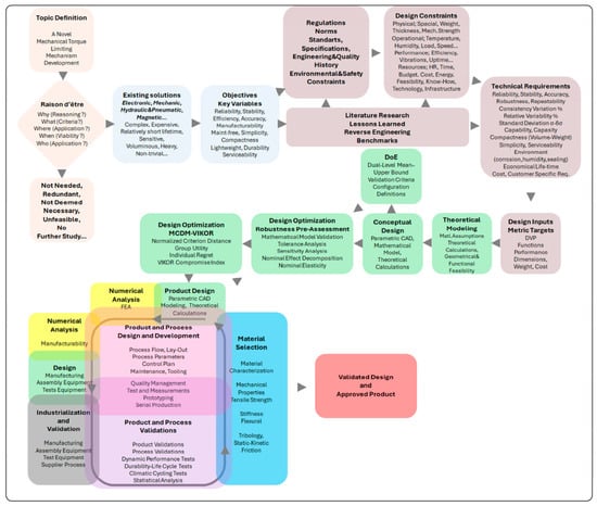
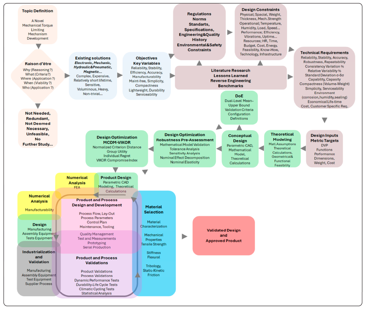
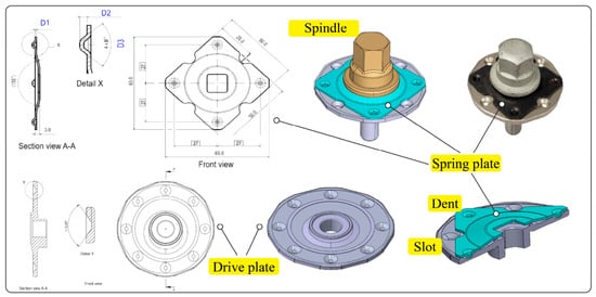
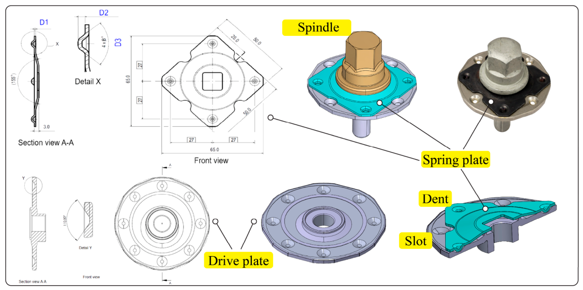
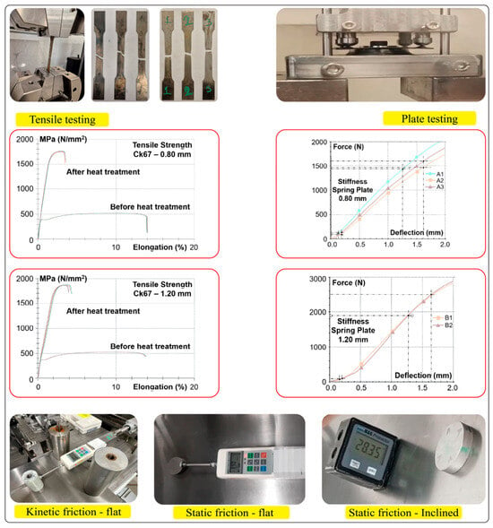
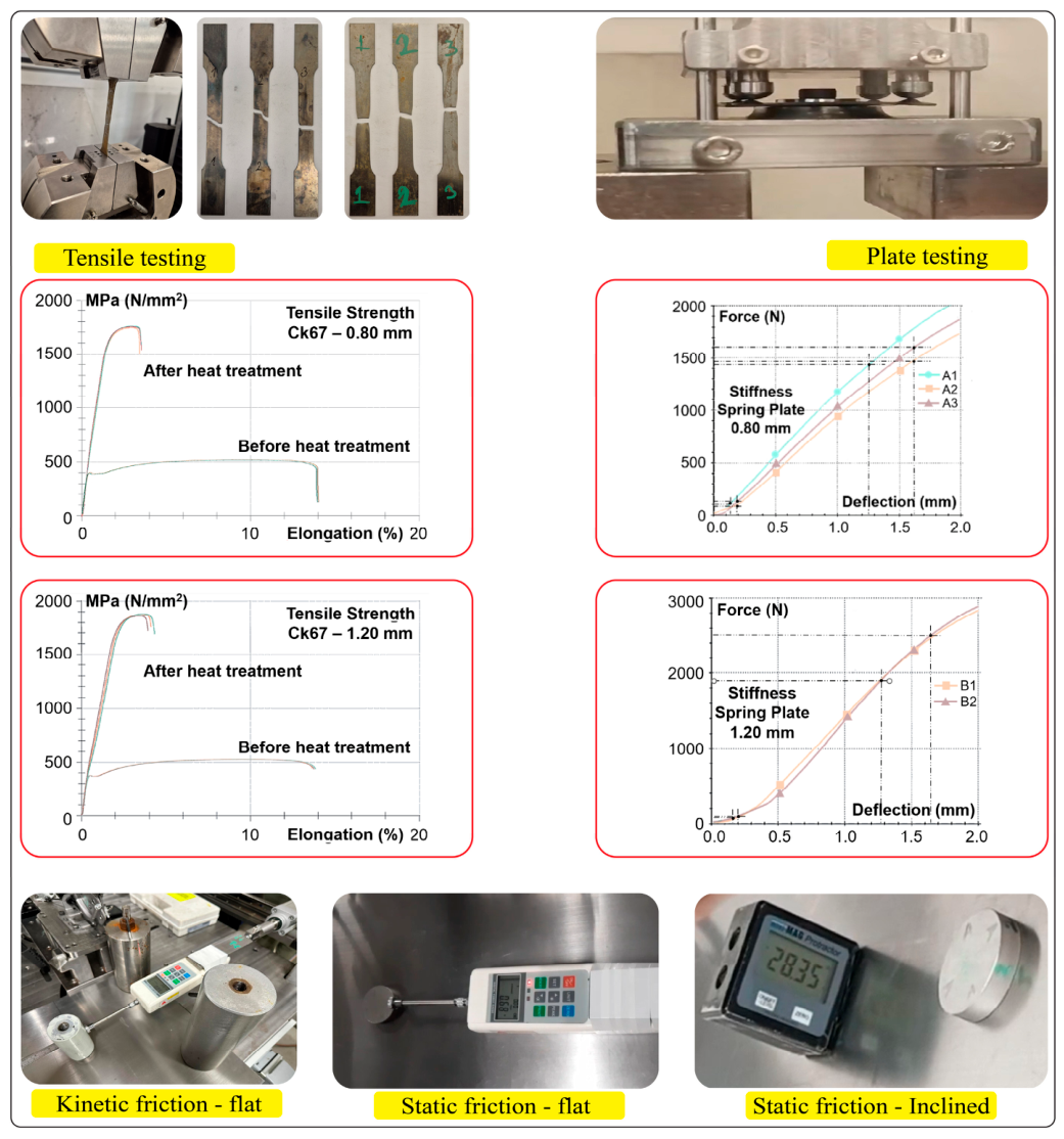
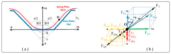
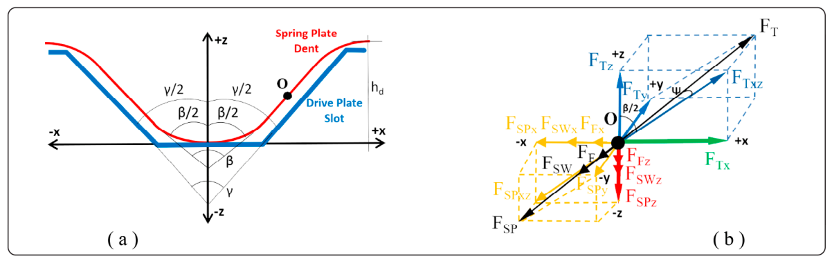
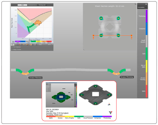
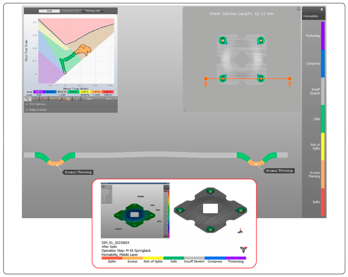
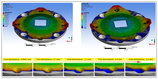
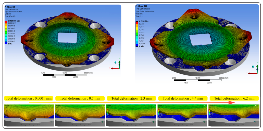
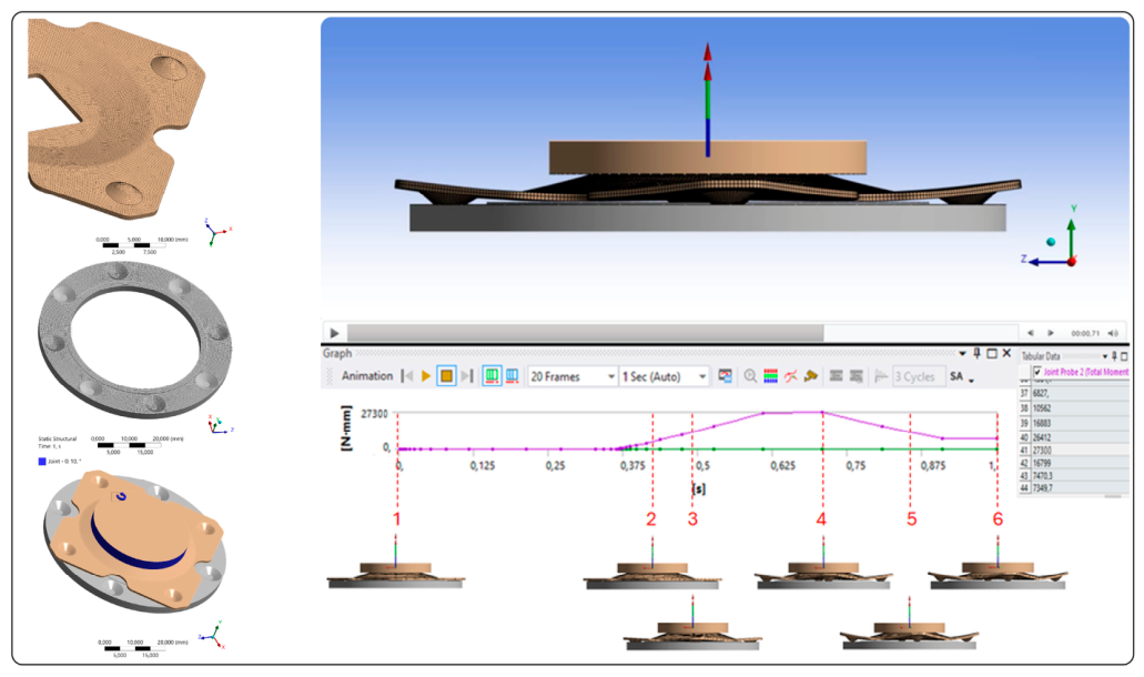
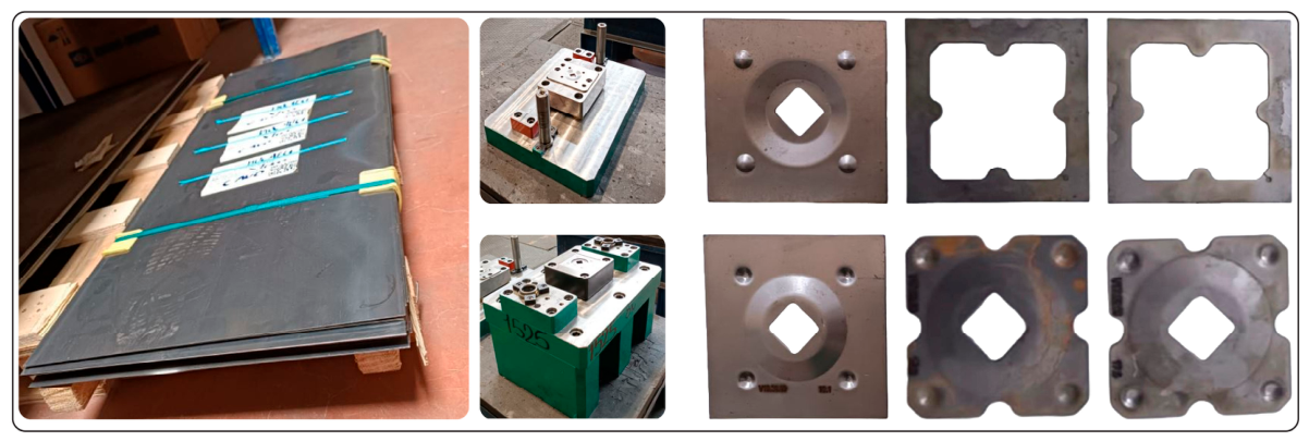
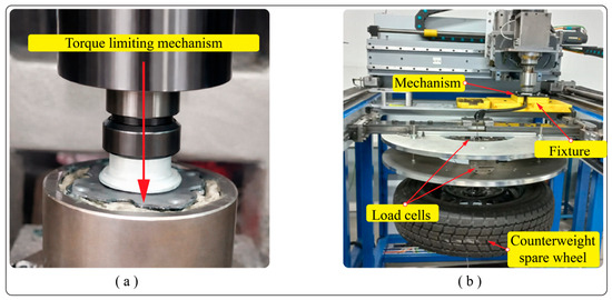
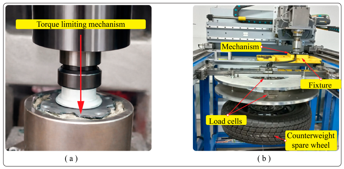
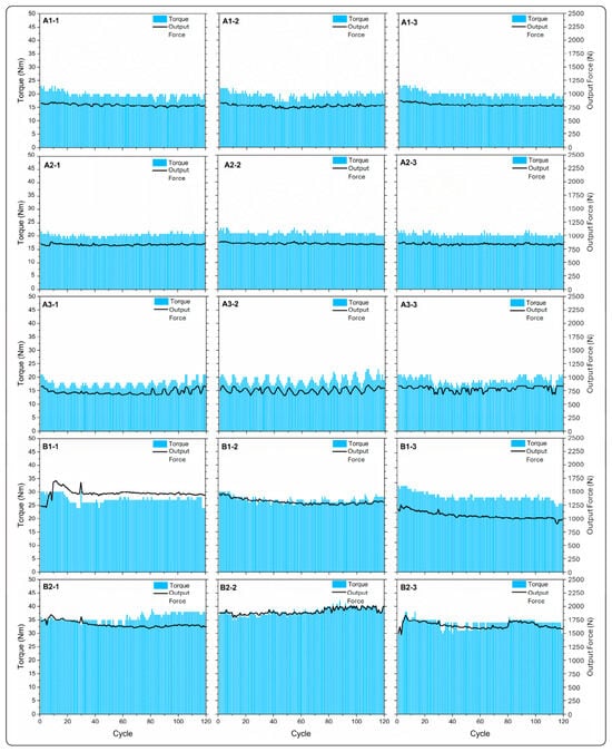
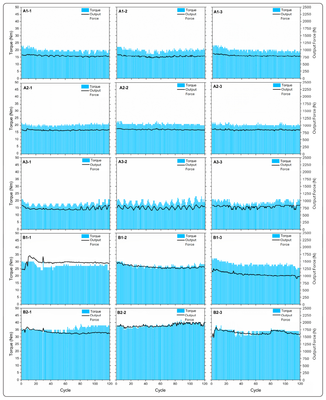
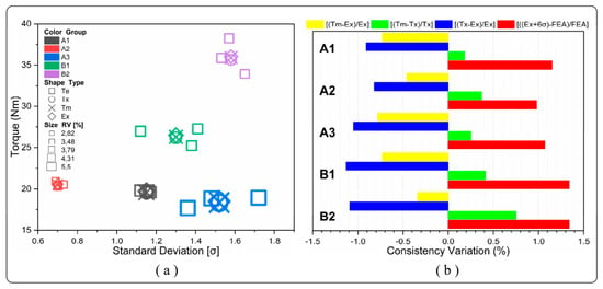
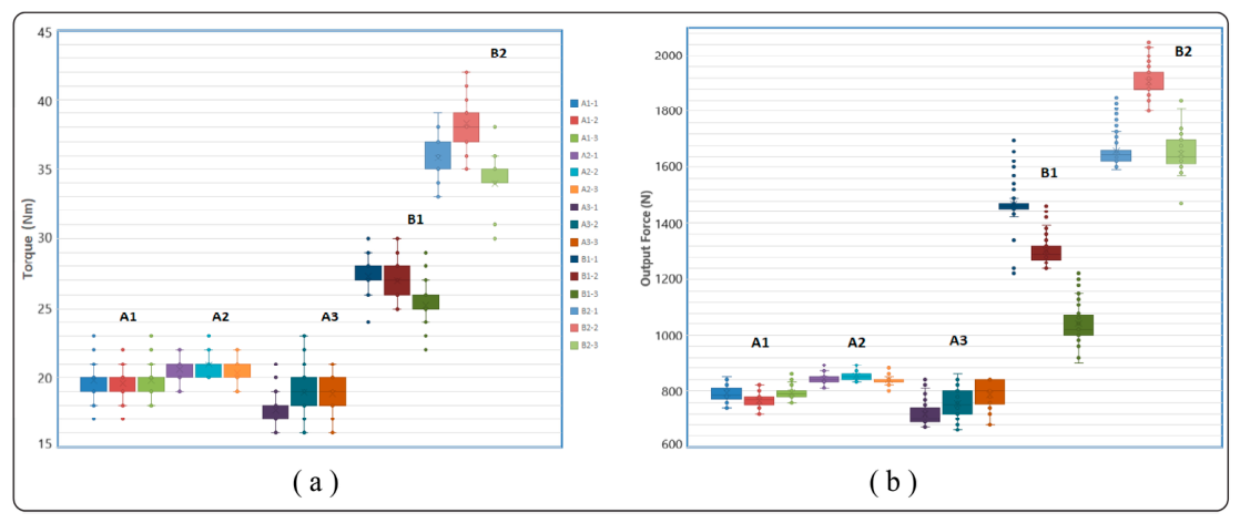
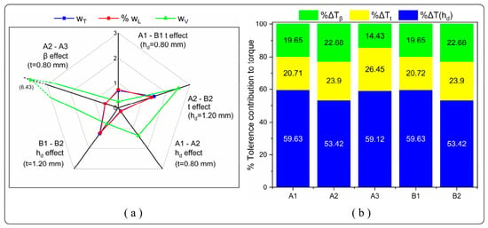
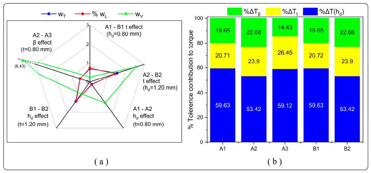

Disclaimer/Publisher’s Note: The statements, opinions and data contained in all publications are solely those of the individual author(s) and contributor(s) and not of MDPI and/or the editor(s). MDPI and/or the editor(s) disclaim responsibility for any injury to people or property resulting from any ideas, methods, instructions or products referred to in the content. |
© 2026 by the authors. Licensee MDPI, Basel, Switzerland. This article is an open access article distributed under the terms and conditions of the Creative Commons Attribution (CC BY) license.