


Abstract
This paper presents a virtual sensor for the in-process prediction of cutting forces from feed drive current measurements in milling processes via inverse filtering. Components of the feed drive current in ball-screw drives that are related to inertia, friction, and gravity are separated from the cutting-force-related component via models or air-cutting experiments. Impact hammer tests are then used to identify the transfer function between forces at the tool tip and the corresponding response at the feed drive. The proposed inverse filtering approach completes the virtual sensor for online monitoring of cutting forces based on feed drive current signals. Compared to existing approaches, which are mainly based on Kalman-filter or deep learning models, this method avoids the additional effort for modeling, parameter identification and generation of training data. Experimental results are presented for cutting tests on a three-axis turn-milling center. The prediction error between the virtual sensor and the measured cutting forces lies between 6% and 17%, depending on the cutting parameters. In general, the virtual sensor can be implemented in any feed drive system with a minimal effort for parameter identification.
1. Introduction
Accurate and reliable process monitoring is important for the advancement of machining technology and performance [1], e.g., in terms of tool health monitoring [2] or predictive maintenance [3]. In particular, knowledge of the cutting force is of key importance for the design and optimization of metal cutting processes and cutting tools, for process modeling and machinability tests, as well as for real-time control and monitoring of the processes [4]. Another advanced example is the estimation of workpiece quality via a Digital Twin based on cutting forces [5]. There are different methods for acquiring cutting force data [4,6]. Dynamometers for direct measurement are rarely used in industrial applications due to their high commissioning and maintenance costs. Moreover, these so-called invasive cutting force measurement systems add mass or inertia, reduce stiffness and can interfere with tool or pallet change. This leads to a strong interest in indirect approaches for estimating cutting forces from other sensors, which are already installed in the machine tool and where the cutting force is determined from the sensor values via additional models. These kinds of approaches are known as dynamic observer, soft sensor or virtual sensor (in the following we refer to this as virtual sensor). The advantage of virtual sensors lies in the fact that available machine-internal sensor signals or signals from easily applicable and non-invasive additional sensors can be used as input signals. They are typically cheaper than direct measurement systems, which makes them compatible and recommended for industrial applications [4].
Virtual sensors for cutting force estimation can be categorized according to the signal type (acceleration, current, displacement, etc.), the modeling approach (Kalman filter, deep learning), or the data source (machine-internal or additional external sensors). One cost-efficient, sensor-based approach is the use of an acceleration signal from an accelerometer positioned close to the tool center point (TCP). The transfer behavior between acceleration and cutting force is modeled, e.g., via a Kalman filter [7] or via machine learning (ML) approaches [8]. However, the use of an accelerometer retains some of the disadvantages associated with external sensors, although accelerometers are often cheaper and easier to integrate into a machine than force sensors. Apart from acceleration, the feed drive motor current has often been used as a potential model input. Historically, this also required an additional sensor for current measurement [9]; however, more recent machine-internal controllers of the servo drives allow the acquisition of current signals directly through the machine controller. Using machine-internal signals from the CNC controller is a very cost-efficient way of determining cutting forces, albeit within certain limitations. These limitations include physical constraints, such as electro-mechanical effects that may influence the motor current signal in addition to the cutting force, as well as technical constraints, such as the sampling rate of the control interface used for data acquisition. Therefore, machine-internal signals, especially current, have become widely regarded as valuable for cutting force estimation.
Most approaches for modeling the relationship between feed drive current and cutting force can be separated into two major categories: Kalman filter-based approaches [10,11,12,13] and ML approaches [14,15,16]. The latter one requires a comparatively large set of labeled data for training of the ML models, where labeled data typically means that actual cutting forces need to be measured with a separate reference force sensor. In recent research, this disadvantage has been addressed, for example, by approaches such as unsupervised domain adversarial adaptation, which reduces the amount of required labeled training data [17]. On the other hand, Kalman filter-based cutting force estimation requires, in general, a smaller amount of the measurement data. Nevertheless, the setup of a Kalman filter, as described in [12], requires the definition of a model for the machine dynamics and some parameter identification of covariance matrices for process and measurement noise. Furthermore, hybrid approaches exist that combine different signal types, modeling approaches and data sources. For example, [16,18] use additional position data from the machine-internal encoders at the drives and motors for a more accurate force prediction. Other examples are the combination of motor current signals from the control and acceleration signals from an external sensor, which can be fed into a multi-input Kalman filter [19] as well as evaluated selectively or fused for certain excitation frequency ranges [20].
In general, there are many promising approaches for indirect cutting force estimation with virtual sensors, which might be suitable for industrial applications. However, given the aspect that the virtual sensors need to be separately tuned at least for each individual machine, feed drive axis, or process condition, the required effort for modeling and/or training data generation is still too high for a wide implementation in industrial applications. Therefore, in this paper, we present a new virtual sensor approach for determining cutting forces from feed drive current signals, which is only based on some basic experimental impact hammer and axis movement tests. In the present approach, the measured transfer function between forces at the tool tip and the feed drive current from impact hammer tests, can be directly used for cutting force estimation by using the inverse filtering approach from [21]. There is no need for an additional Kalman-Filter or ML approach, and all remaining modeling parameters can be directly readout from the numerical control of the machine. Therefore, the proposed method provides two major advantages. The first advantage is that the setup of the method in a new machine requires only a minimal number of experiments, using standard experimental equipment (impact hammer with data acquisition system). The second advantage is that the setup and parameter identification method can be semi-automated in a straightforward procedure and, hence, can be easily adapted for the use on many different machines and feed drives.
The paper is organized as follows. Section 2 introduces the modeling approach for separating the different components of the feed drive current. The estimation of cutting forces from the force-related component of the feed drive current via inverse filtering is described in Section 3. The practical implementation, including experimental modeling results for a three-axis turn-milling center, is given in Section 4. Section 5 presents an experimental verification using cutting experiments, followed by concluding remarks in Section 6.
2. Modeling and Identification of Feed Drive Current
For CNC machines, the motor current of the feed drives is nearly proportional to the torque that is produced by the motor
The constant [Nm/A] in Equation (1) is called torque constant and can be found in the machine data or motor specifications. In machine tools, the torque produced at a feed drive generates the axis motion and can be decomposed into several components [12,22]. This decomposition can also be applied to the torque-producing feed drive current according to Equation (2). First, we divide the motor current into the so-called air-cutting current and the cutting current
The air-cutting current is related to the torque required to produce axis movement in air without any additional external force on the feed drive such as a cutting force on the tool tip during metal cutting. The cutting current is the component that compensates the cutting forces . The feed drive current can be measured during machining. If the air-cutting current is known for the specific axis movements of the feed drive during machining, Equation (2) can be used to identify , which is directly related to the cutting force on the tool tip (see Section 3 for further details). In principle, the air-cutting current can also be measured by performing the axis movements of a CNC program without an air workpiece [23]. However, this procedure has several drawbacks, e.g., it requires additional machining time that cannot be used for production, and time synchronization of the two measurements is not straightforward especially for time-intensive part programs. Therefore, it is useful to model the air-cutting current.
The air-cutting current can be divided into three main components
which compensate the different components of the motor torque for creating the axis movements. is the current that compensates inertial forces during axis acceleration. is the current to overcome frictional forces in the motor and other parts of the feed drive, and the static component is related to gravitational forces that appear, e.g., in vertical axes. The current , related to inertial forces, can be calculated by
where is a constant related to the inertia of the axis and the torque constant , and is the acceleration of the axis.
For the current related to friction forces we use an asymmetric Coulomb friction model with an additional viscous component as given by
This friction model has the velocity v as a variable and introduces the parameters and d representing the constant of the Coulomb friction and the proportional factors of the velocity-dependent viscous friction, respectively. Note that, depending on the machine configuration, the constants can be also negative. The proposed model in Equation (5) can be replaced by more advanced models, which also consider pre-sliding, hysteresis and the Stribeck effect, for example, by using the LuGre model [12,24]. These effects are especially relevant for low axis velocities but also require significantly more experimental effort for accurately determining the model parameters. Here, we focus on processes with significant velocities v and preferably low effort for the model setup. Therefore, we use the model Equation (5), which is widely applicable in these cases and requires only a minimum number of experiments for model identification.
The current related to gravitational forces is constant and vanishes for horizontal feed drive axes. Note that for vertical axes, in general, cannot be calculated by Equation (4) via substitution of the acceleration a by the gravitational constant g. This is due to the fact that the machine tool may contain some weight compensation for vertical axes, e.g., hydraulic cylinders, that reduce the effort to lift a vertical axis.
For the identification of the model parameters for the different components of the air-cutting current in Equation (3), first the constant gravitational component is identified by continuous motion of the axis in air in two directions with the same absolute velocity . In this case, we have and because . Then, according to Equations (2), (3) and (5), the overall motor current can be given as
where is the current in the positive direction of axis movement () and is the current in the negative direction of axis movement (). From Equation (6) the constant gravitational component can be determined by
For this test, it is recommended to use a significant velocity (e.g., 200 mm/min) to avoid disturbances due to pre-sliding and other friction effects that become very complex at low velocities. Additional similar measurements and of the motor current for axis movements in positive and negative direction, respectively, with various constant velocities are then performed to identify the parameters of the friction model by using
After identification of the models for the friction component and the gravitational component of the motor current, the inertia-related constant of the motor current can be identified by axis movements with different constant accelerations .
3. Cutting Force Estimation via Inverse Filtering
The main part of the virtual sensor or virtual sensor approach is the cutting force estimation from the cutting-related component of the feed drive motor current. In general, the transfer behavior between a time-dependent cutting force signal at the TCP of a machine tool and can be described via a frequency response function (FRF) [A/N], which is formally defined by
where in the rest of the paper denotes the Fourier transform with the angular frequency of some function . Moreover, denotes the amplitude of the Fourier transform and its phase. For simplicity, in Equation (10) we assume that the cutting force aligns with the direction of the feed drive motion. For the identification of multiple cutting force components from multiple feed drives, which is relevant, for example, in five-axis milling, kinematic transformations can be used for mapping force components to machine axes [12]. We further assume that cross coupling between the axes can be neglected, meaning that, for example, an applied force component in the direction of the machine’s x-axis only provokes a significant reaction in the current signal of the feed drive motor of the x-axis. Equation (10) implies that there is a linear and time-invariant electro-mechanical transfer behavior from forces at the TCP to the motor current. This assumption holds in general for feed drive axes, which move with a significant velocity. For low velocities, for example, stick-slip friction effects and hysteresis are likely to occur that could result in a pronounced nonlinear transfer behavior and low estimation quality (cf. [18,25]). As a simple example, for a typical ball-screw feed drive in CNC machines and a constant cutting force , we can write
where is the pitch length of the ball-screw. However, in general, the cutting forces are time-varying, which means that Equation (11) is not applicable and instead the dynamic FRF defined in Equation (10) is relevant.
The FRF can be determined experimentally via impact hammer tests. In particular, the TCP is excited by an impact hammer with force that represents the cutting force. Meanwhile, the motor current in response to the hammer hit is measured via the CNC controller. Then, the FRF is determined by
The impact hammer tests are performed at a moving feed drive axis with constant velocity to minimize disturbances from backlash, hysteresis or nonlinear friction effects such as pre-sliding. In this case, a calculation of the air-cutting current and compensation of , and is not necessary for the measured motor current because for the experimental conditions (constant axis velocity) the inertia related component vanishes , and the other two components are constant. Therefore, the air-cutting current is constant , which only leads to a constant offset of the motor current in the time domain and some deviation in the FRF value . Since impact hammer tests are, in general, not very accurate at frequencies close to zero, the static transfer factor , i.e., the value of the FRF for frequencies needs to be corrected with values determined by other methods, for example, a calculation based on Equation (11).
For determination of the cutting force from a motor current signal, the formal inverse of the transfer function is required. However, in practice a simple inversion of the complex function causes severe problems, e.g., amplification of noise at low amplitudes leads to ill-conditioned results. Therefore, a causal and stable filter is required, which represents the inverse FRF. Here we propose using the inverse filtering approach from [21,26] as an efficient alternative approach.
The first step in this approach is the transformation of the measured FRF into a minimum-phase representation. The minimum-phase FRF is obtained by the following procedure [21]:
where and denote the Fourier and inverse Fourier transform, respectively. The sequence is called the cepstrum of the real sequence , and is the minimum-phase representation of the FRF . The advantage of the minimum-phase representation is that it is stable and causal and, hence, its inverse is stable and anti-causal.
After calculation of the minimum-phase FRF directly from the measured FRFs, the second step of the presented approach is the identification of a digital filter which reflects the minimum-phase FRF . A digital filter can be described by a transfer function in z-representation as
with the numerator coefficients , and the denominator coefficients , . The identification of the filter parameters and for a given transfer function is a standard problem in curve fitting and filter design. Here we use the MATLAB function invfreqz, which is based on an algorithm from [27,28] and can be used to fit any FRF for given numbers N and M of numerator and denominator coefficients, respectively.
As a third step the discrete minimum-phase filter is inverted such that it can be used for the calculation of forces from measured motor current samples in real time. The inverse filter can be obtained from by simply switching the denominator and numerator coefficients. Therefore, the inverse filter can be given as
The filter defined in Equation (18) calculates the cutting force at a discrete sampling time for a given sequence of the cutting current .
4. Practical Implementation
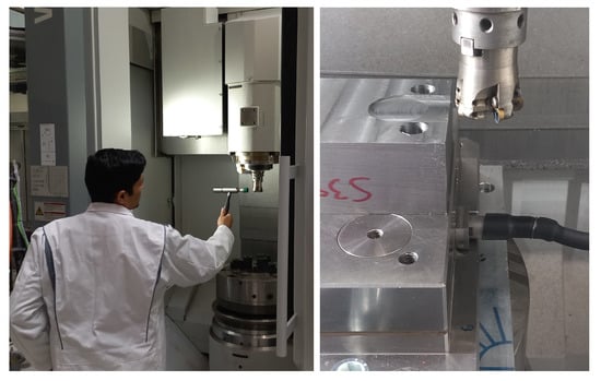
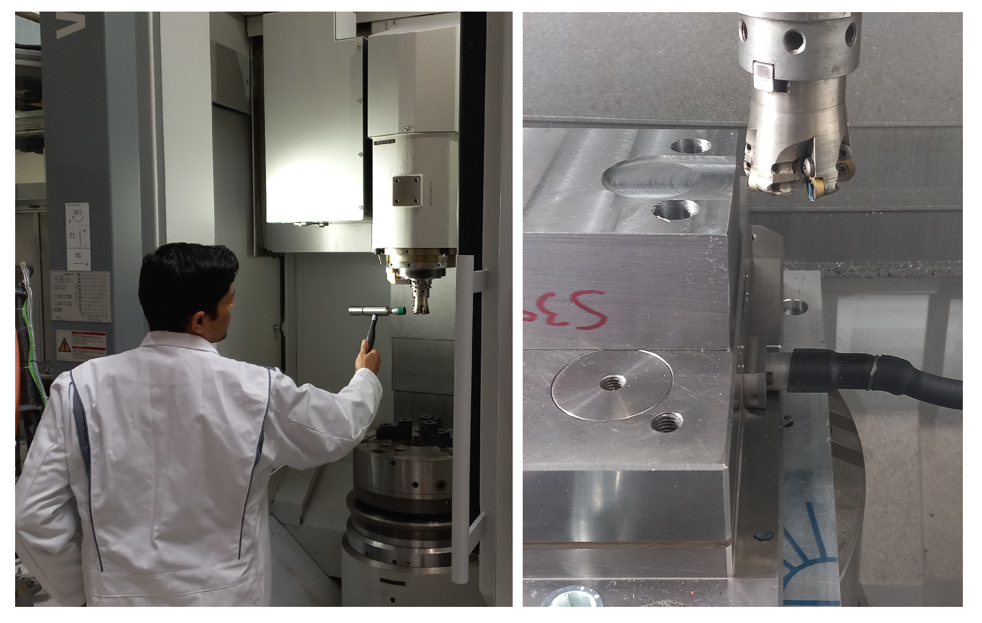
The practical implementation and experimental verification are shown for a three-axis turn-milling center EMAG VMC 300 MT (see Figure 1) with a Siemens Sinumerik 840D sl controller. The machine has two linear NC-axes for horizontal (X) and vertical (Z) movement of the milling spindle and one rotational NC axis (C) for workpiece rotation in turning processes and realization of three-axis milling processes. The motor current of the feed drives can be traced via a specific controller function with the servo sampling rate of . In this paper, we consider only forces in the x-direction of the EMAG machine. The torque constant of the motor and the pitch length of the ball-screw can be read from the associated NC variables in the machine controller. For the x-axis the values are Nm/A and mm. For the setup of the method, two types of experiments are necessary.
Figure 1.
Experimental setup of the impact hammer tests (left) and cutting experiments (right).
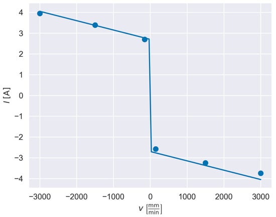
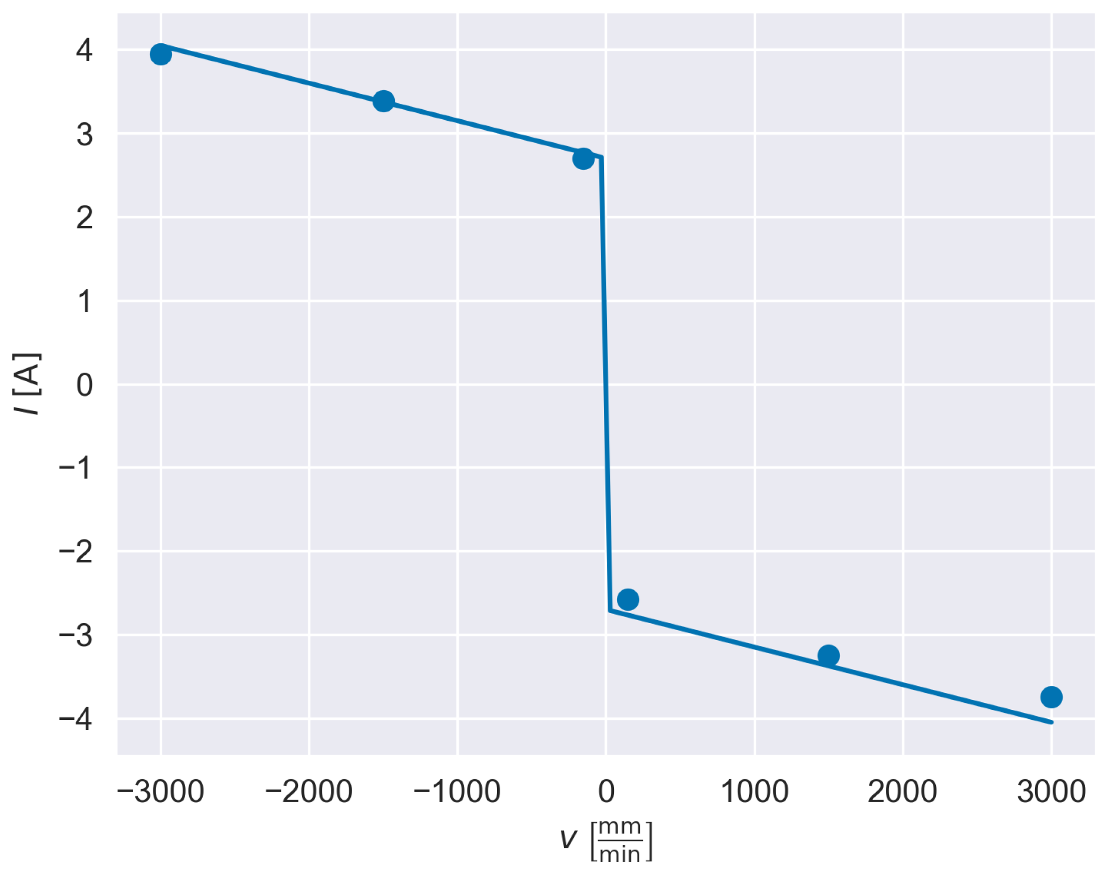
The first type is air-cutting experiments, i.e., standard movements of the feed drives without workpiece for identification of parameters of the model for the air-cutting current in Equation (3) as described in Section 2. For these types of experiments no additional experimental equipment is required. Since the x-axis is horizontally aligned, we have no significant current related to gravitational forces, i.e., . The resulting friction model, uwhich is derived from air-cutting movements with different velocities, is shown in Figure 2. We identified the model parameters and for the friction component of the feed drive current. Moreover, from axis accelerations, we obtained the parameter .
Figure 2.
Current measurements (dots) and friction model (solid line) for different velocities of the x-axis.
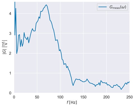
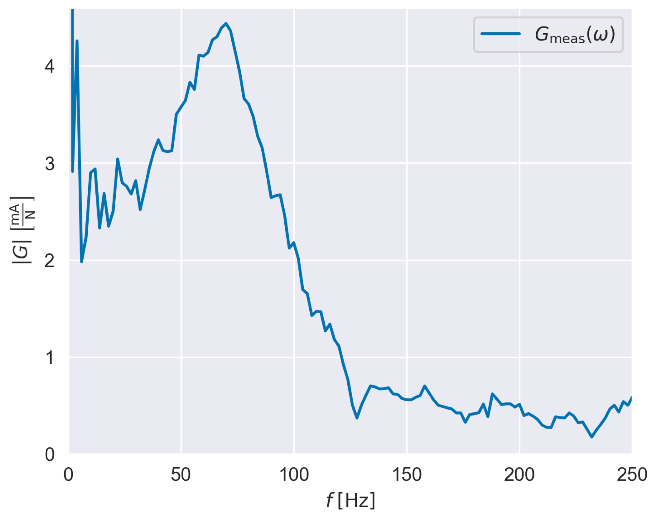
The second type of experiment is the impact hammer test for the identification of the transfer function in Equation (10). For the excitation of the structure close to the TCP we tested the Dytran Dynapulse and Dytran 5802A impact hammer with a maximum force of and , respectively (cf. Figure 1). The results were slightly better for larger excitation forces. Thus, we used the larger impact hammer (Dytran 5802A) for the identification experiments. For the impact hammer tests, we retrieve the feed drive current signal through the analog output of the CNC controller. This setup enabled synchronous acquisition of both analog signals, the excitation force from the impact hammer and the feed-drive current, using the same DAQ system. We used the 4-channel DAQ module NI 9234 that contains an AD-converter and is connected via USB port to a measurement laptop. Signals are measured with a sampling frequency of . During impact testing, the axis was moving with a velocity of to avoid disturbances from nonlinear friction such as pre-sliding, hysteresis, and the Stribeck effect. The values of the measured FRF are shown in Figure 3. The maximum frequency of is given by the Nyquist–Shannon theorem due to the servo sampling time of ms.
Figure 3.
Experimentally measured FRF of the x-axis feed drive.
There are two limitations that can be seen in the raw values of the FRF measurement. On the one hand, for excitations with frequencies larger than it can be seen that the amplitude of the FRF becomes very small. This means that for forces with frequencies larger than only a small feed drive current can be detected, which is a physical limitation of the mechanics of the feed drive systems. Conversely, this means that high-frequency noise in the motor current signal will be amplified by the inverse FRF in the calculation of the cutting force. Therefore, the measured and identified cutting current is low-pass filtered via a fifth-order Butterworth filter with a cut-off frequency of before using the signal to calculate the cutting force. On the other hand, measurement quality for low frequencies is not very good. There are some disturbances below and large deviations below . This is due to a limitation of the test procedure, which does not provide reliable excitation at near-static or very low frequencies. Therefore, the static transfer factor , which is the magnitude of the FRF at is calculated via Equation (11). With the parameters of the x-axis, we obtain × . The amplitude of the FRF is set to this value for frequencies up to to obtain the modified FRF .
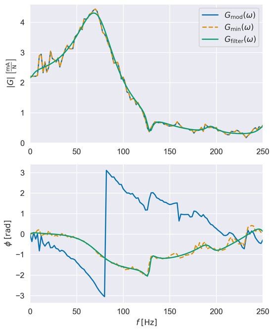
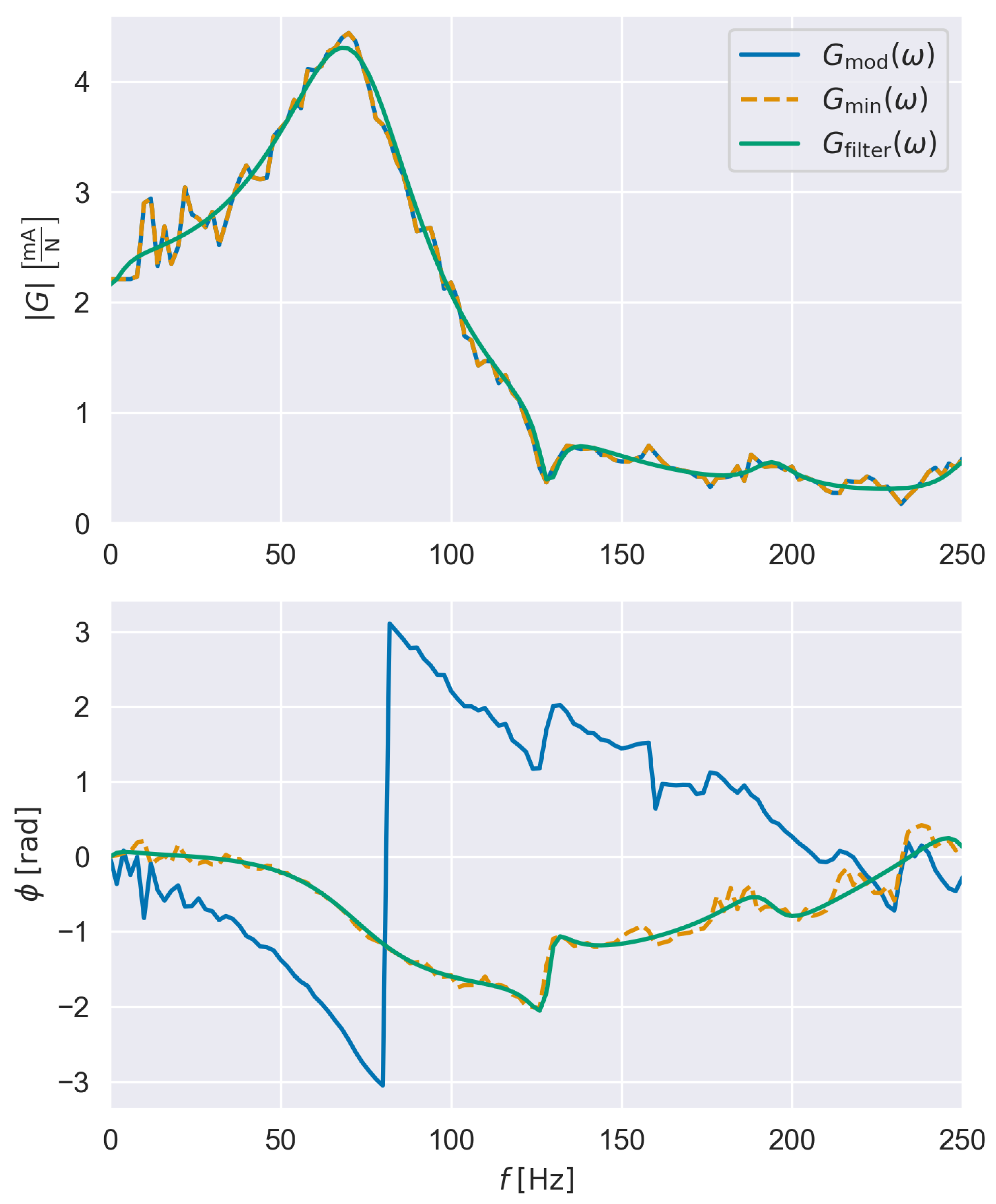
The modified FRF is then used to create the minimum-phase representation according to Equation (16) and to identify the digital filter via the MATLAB function invfreqz as described in Section 3 from the minimum-phase representation. In this paper, we chose as the maximum degree for the numerator and denominator, respectively. After the identification, the FRF of the filter can be obtained. The modified, measured FRF , its minimum-phase representation , and the FRF of the identified filter are shown in Figure 4. The magnitude of , which is its non-minimum-phase, and its minimum-phase representation are basically identical. However, the phase of has been altered to fulfill the properties of a minimum-phase representation. Furthermore, approximates very well. There are only small deviations in the magnitude at low frequencies, where the measurement quality was not very good. To ensure that the identified digital filter is causal and stable even after its inversion, the zeros of the identified transfer function have been calculated, and indeed, all zeros lie within the unity circle.
Figure 4.
Modified FRF of x-axis, its minimum-phase representation and FRF of identified filter .
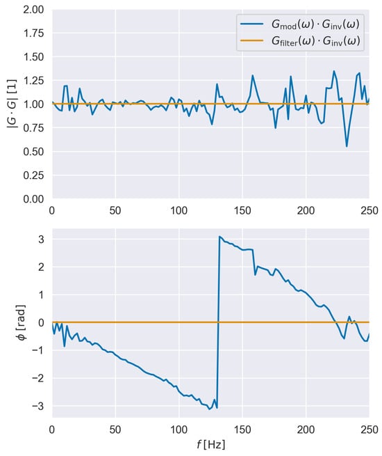
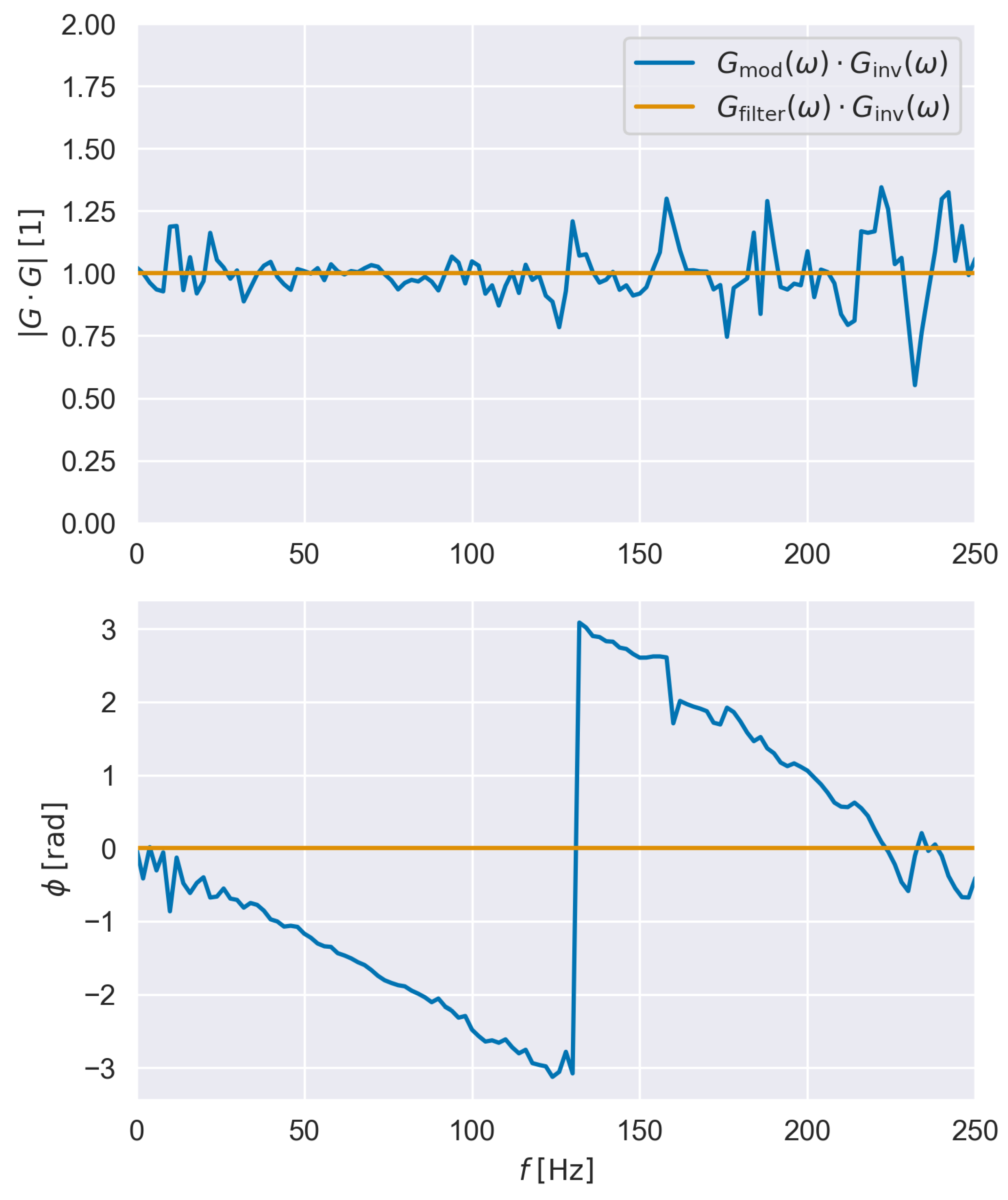
The calculated digital filter was then inverted according to Equation (18). An initial verification that the inverted filter can be used for an accurate calculation of forces from feed drive motor currents is performed by multiplying the FRF from the inverted filter with the measured and modified FRF . The magnitude and the phase of this product are shown in Figure 5 together with the product of and , which is equal to one as a reference.
Figure 5.
Verification of the inverse filtering approach via sequential application of modified FRF and filter FRF with FRF of the inverse filter .
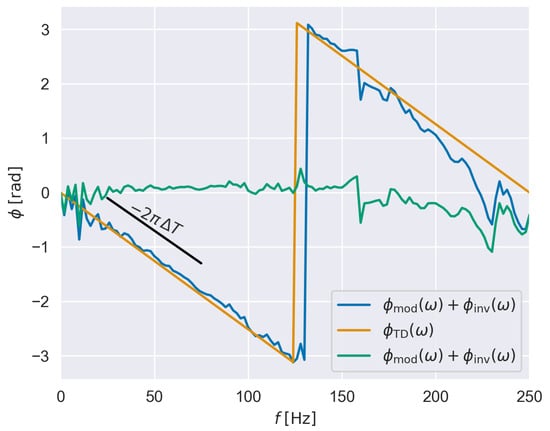
For frequencies up to , the magnitude of the product is relatively close to unity, with larger deviations at lower frequencies. If is multiplied by its inverse , the deviation in magnitude as well as phase can be neglected. The phase of , which equals , is almost linear. This linear offset in phase translates to a constant offset in time and is a result of the derivation of from via the minimum-phase transformation (cf. phase plot in Figure 4). The FRF of a pure time delay can be defined as follows:
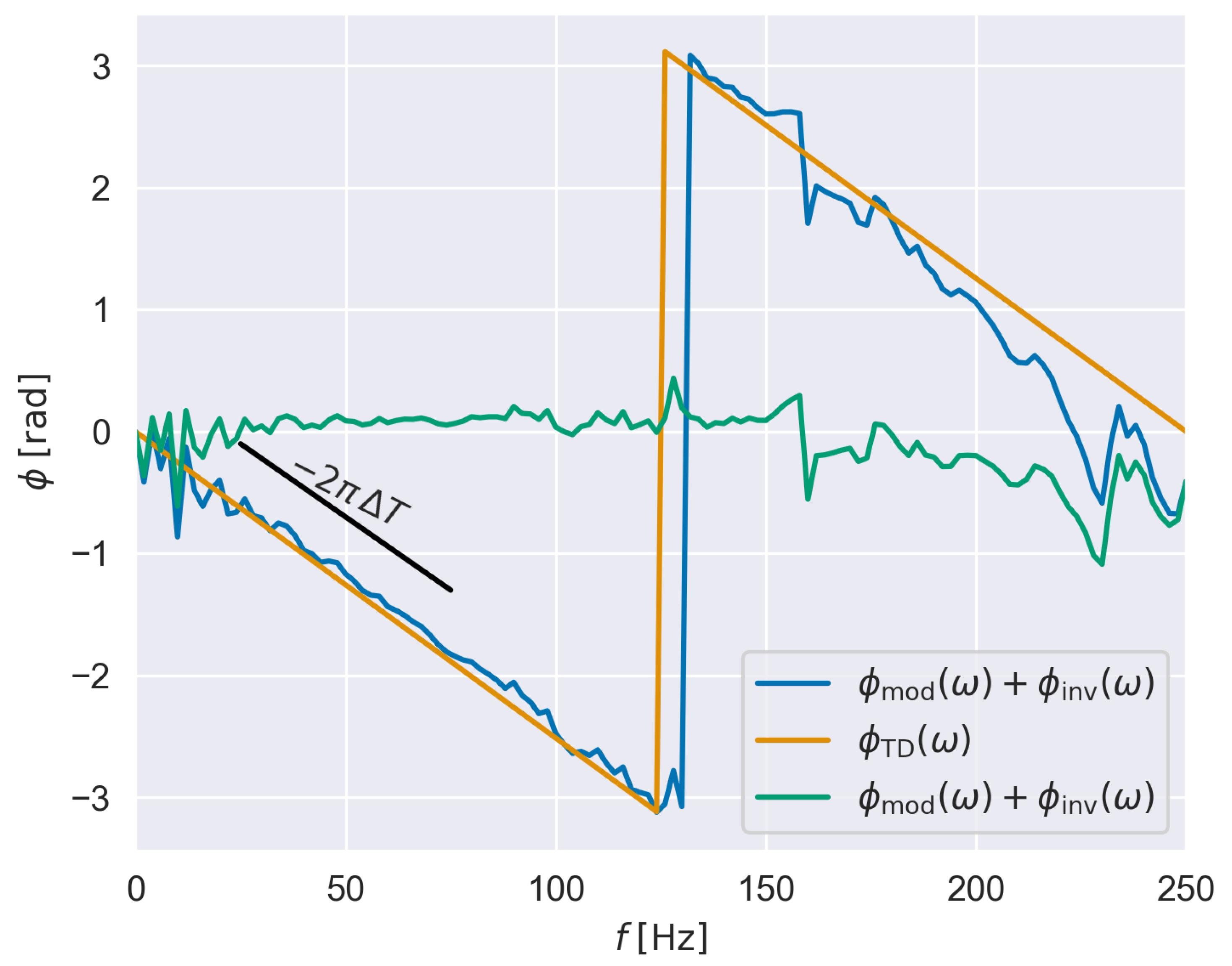
The time delay represents the negative slope of the linear phase of . The nearly linear negative slope of the phase is estimated as ms, as can be seen in Figure 6 showing in comparison to . By subtracting from , the phase difference in the verification is strongly reduced, which is also shown in Figure 6. In other words, if the output of the inverse filter is corrected by a time shift of ms, it represents a reasonably good inversion of the measured, modified FRF . In terms of cutting force estimation by the inverse filter , this correction means that the output force signal of the inverse filter needs to be shifted by ms (ms in negative time direction) to match the actual forces in time.
Figure 6.
Remaining phase error of the inverse filtering approach (), phase of identified time delay (), and verification of the phase after compensation with .
5. Experimental Verification with Cutting Experiments
For the experimental verification, we performed cutting tests with a different set of spindle speeds, feed rates, and axial and radial depth of cuts (see Table 1). For the cutting tests, the actual cutting force was measured by a Kistler dynamometer 9255B on the workpiece side (see Figure 1). A multichannel charge amplifier Kistler 5070 was used to convert the charge signal from the Kistler dynamometer to an analog voltage signal, which was then acquired via the DAQ module NI 9234. The signals were sampled with Hz. All milling operations were performed with a five-blade face-milling cutter with a diameter of mm on an S235 steel cuboid workpiece. For verification purposes, cuts along the x-axis of the machine were performed. For experiments with a partial engagement of the tool, a groove was machined beforehand.
Table 1.
Parameters of cutting experiments.
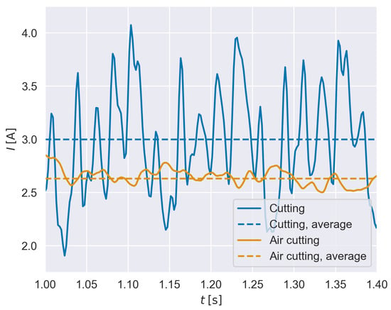
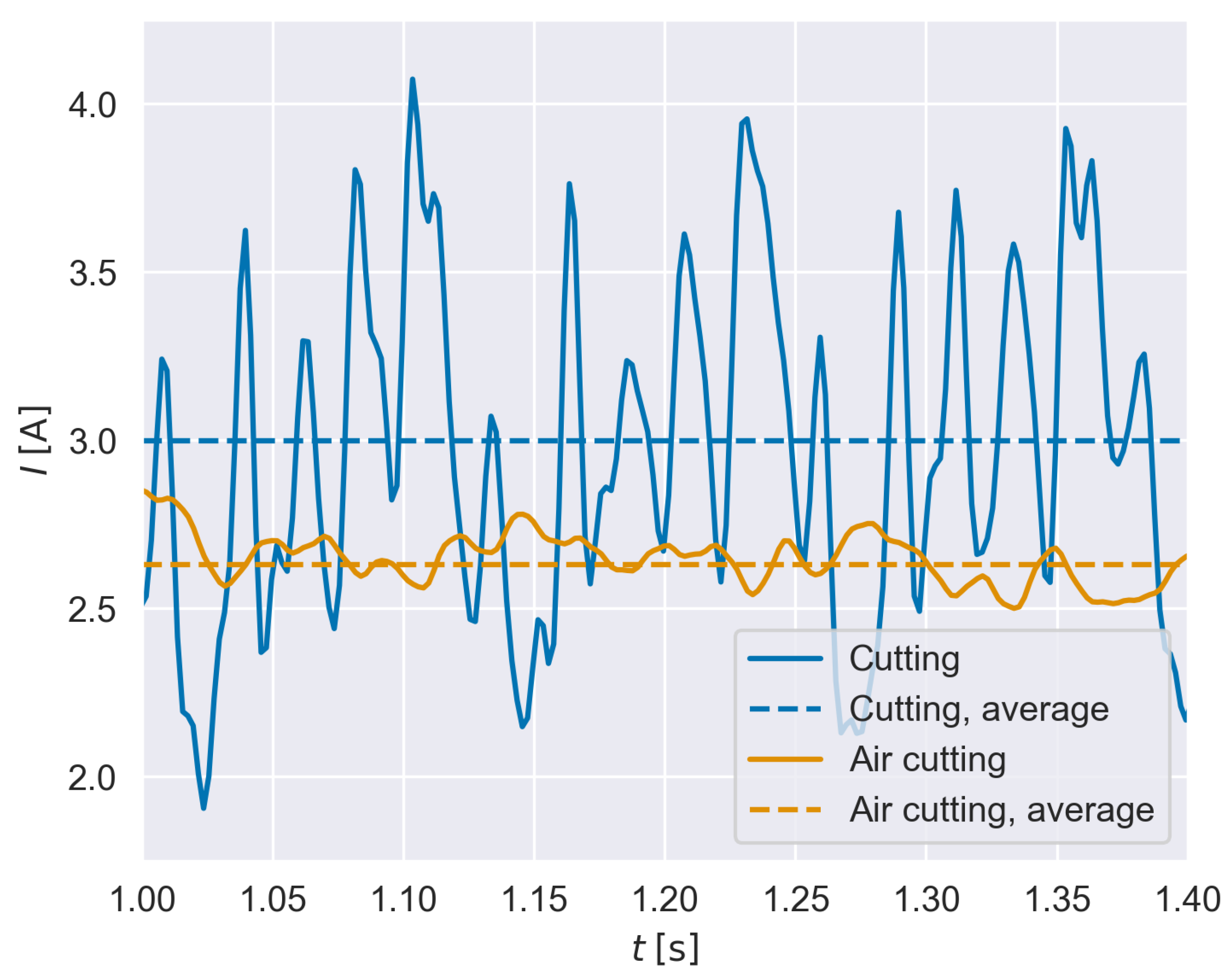
First, we verified the static transfer factor , which was previously identified via Equation (11) based on average measured cutting forces. All cutting processes of the individual experiments can be considered stationary after the tool is fully engaged, which means that oscillations of the force occur but the overall cutting conditions (feed, spindle speed, and axial and radial depth of cut) remain constant. This is a prerequisite of the approach. An excerpt of the current signals for Experiment 1 and the related air-cutting experiment is displayed in Figure 7. In comparison to the air-cutting experiment, it can be seen that the cutting forces not only lead to stronger oscillations in the current signal but also to an offset of the average current between air-cutting and cutting.
Figure 7.
Current signal of Experiment 1 in air and during cutting.
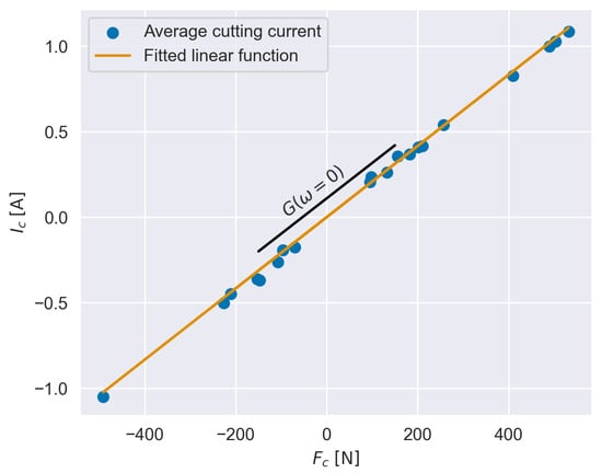
This offset can be used for the identification of the static transfer factor . Therefore, the averages of measured cutting forces and cutting currents of the individual experiments are observed. To obtain cutting current from the measured average total current , friction must be compensated via one of the earlier presented methods. We used the average current measured during the related air-cutting experiments , which is subtracted from .
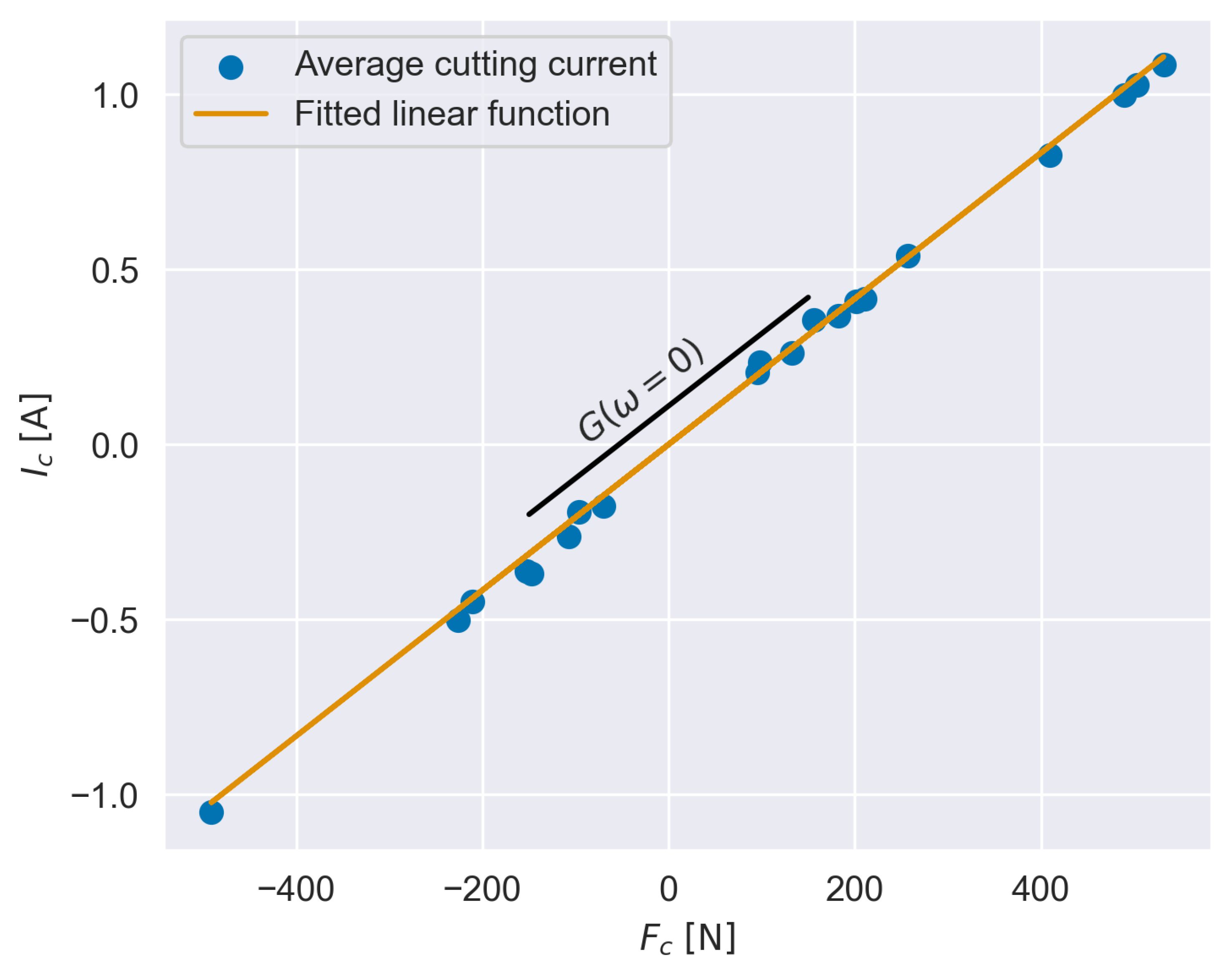
The average cutting currents can now be plotted over the average cutting forces, which is illustrated in Figure 8. The points indicate a linear relation between the two quantities. This relation can be described by a linear function without an ordinate offset. The slope of the function, which can be identified via a least-square optimization, is the static transfer factor (see Figure 8). With this method, the static transfer factor is identified as . Hence, the approach introduced in Section 4 and this second one lead to similar results, with the second approach deviating 9.1% from the first one. As the analytical approach in most cases is more convenient, its value is used in this paper to modify the measured FRF, as stated in Section 4.
Figure 8.
Identification of static transfer factor from cutting experiments (dots).
After the initial assessment of , the estimation quality of the inverse filter is evaluated. To obtain the cutting-force-related current component from the total measured current signal, the motor current from the related air-cutting experiment is subtracted to compensate friction- and inertia-related components according to Equation (2). As the air-cutting signal shows disturbances (see Figure 7), it is smoothed by a moving-average filter before it is subtracted from the motor current .
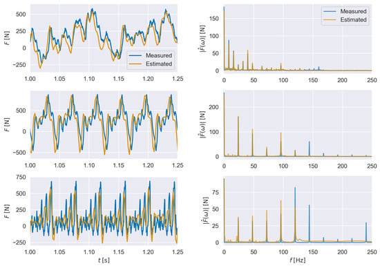
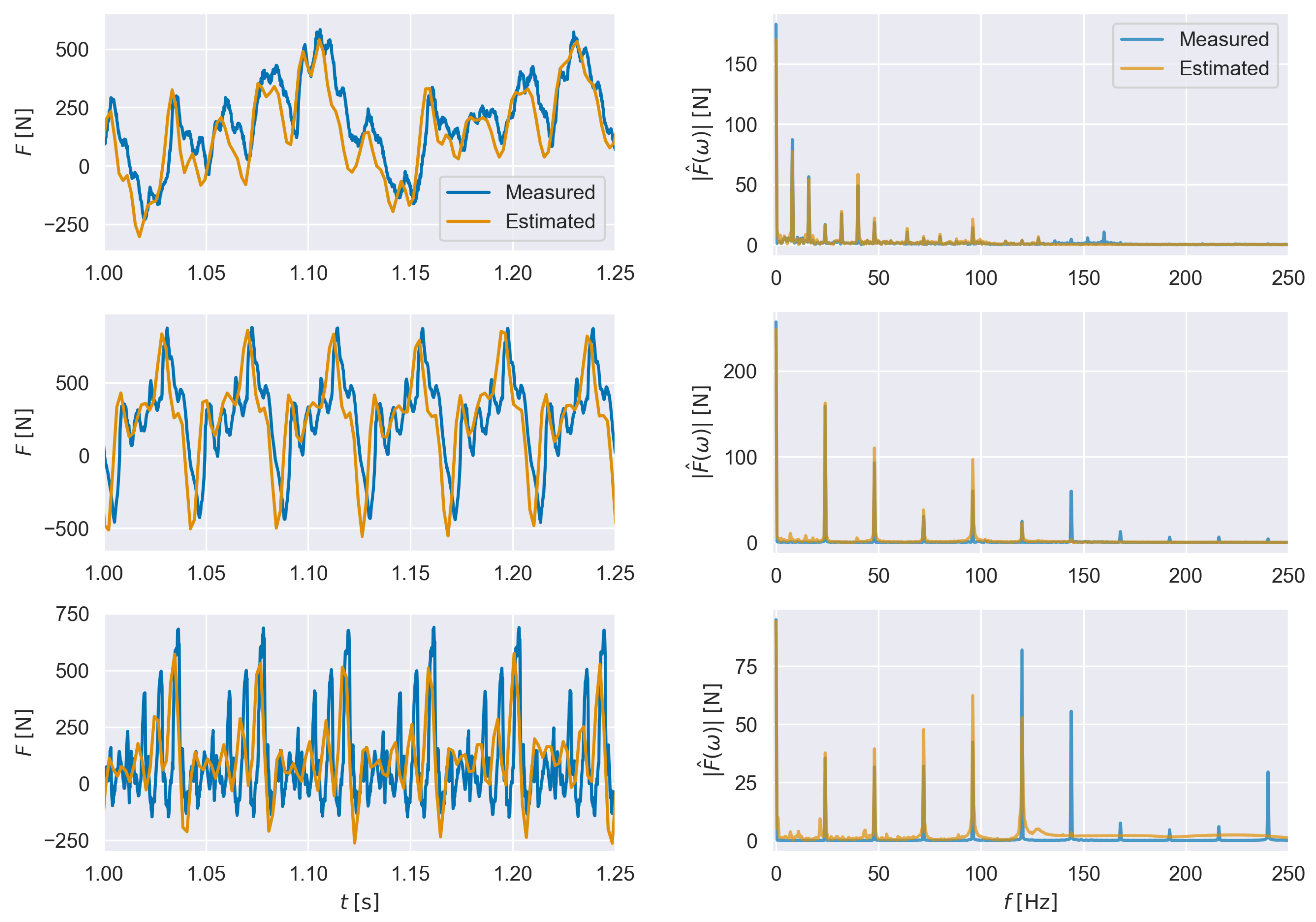
As described in Section 3, the FRF is only valid for frequencies up to ; therefore, the signal is filtered by the Butterworth-filter as described in Section 4. Afterward, the inverse IIR filter is applied to obtain the force signal . Finally, the resulting force signal is shifted by . The results of the virtual sensor for Experiments 1, 8 and 10 are plotted in Figure 9 in time and frequency domains to verify the estimation quality for individual excitation frequencies.
Figure 9.
Comparion of measured and estimated forces for Experiments 1 (top), 8 (middle) and 10 (bottom) without optimized offset in the time domain (left) and amplitudes in the frequency domain (right).
The approach still shows some fluctuations in the time shift between the measured and the estimated signal. In all experiments, the 4 ms delay shifts the estimated force signal too far back on the time axis. This may be caused by synchronization errors between the measured force signal via the dynamometer and the current signal retrieved from the NC.
In general, the estimation quality for Experiments 1 and 8 is acceptable. However, it can be seen that the smaller peaks of Experiment 8 have not been estimated correctly. This is likely caused by the higher spindle speed and, therefore, the higher tooth passing frequency, which leads to significant excitation frequencies above the application limit of the filter. However, the major peaks are estimated comparatively accurately. This accuracy is considerably lower for Experiment 10, which is also due to high spindle speeds, and therefore, high excitation frequencies. In particular, especially for Experiment 10, large peaks with Hz can be found in the frequency spectrum (see Figure 9 bottom, right). The average value of the cutting force signal has been recreated similarly accurate for all experiments.
The deviation of the virtual sensor between measured and estimated cutting forces and is evaluated using the normalized root mean square error, which is defined as in Equation (21).
Here, is the sequence of measured force samples via the Kistler platform, and is the sequence of estimated force samples. Note that is the number of estimated samples, which is lower than the number of measured samples due to the lower sampling rate of the current measurement via the NC compared to the force measurement via the Kistler platform. To calculate the NRMSE, the measured signal has been interpolated to obtain time-matching values relative to the estimated samples. To compensate for the influence of the time offset between the signals, the NRMSE is minimized by introducing and optimizing an additional time offset for each experiment. The calculated offset as well as the corresponding NRMSE are shown in Table 2.
Table 2.
Calculated time offset and NRMSE (after offset compensation) of cutting experiments.
The table shows that Experiment 1 has the lowest NRMSE with a deviation of , while Experiment 10 has the highest NRMSE with a deviation of . Both experiments are displayed in Figure 9.
As a result, this virtual sensor for cutting force estimation is suited for monitoring applications in roughing and face milling at lower spindle speeds. For finishing applications and end mills with low diameter, the sensitivity might be insufficient. Furthermore, the bandwidth limits translate to boundaries in the estimation of high-frequency force components with Hz, which mainly depend on the spindle speed and the number of cutting teeth. The exact frequency limit depends on the mechanical structure of the feed drive system and the CNC controller and may very from machine to machine.
6. Summary and Outlook
A virtual sensor for feed drive current-based cutting force estimation has been presented. The method is based on the identification of the FRF between an excitation force signal and the feed drive motor current signal of a machine using an impact hammer test, as well as on general drive properties such as friction, inertia, and gravitational loads. A filter representing the inverse transfer behavior is then used to replicate the relationship between the current signal and the cutting force. Further influences on the current signal, such as drive friction, inertia, and gravitational loads, can be described by comparatively simple models and compensated before applying the filter. Compared to previous work, the identification process of the filter has been simplified by replacing the Kalman filter with a generalized, inverted minimum-phase filter. The calculation of the minimum-phase representation of the experimentally determined FRF is a straightforward procedure. In contrast to ML approaches for cutting force estimation, this method requires only a minimum number of standard experiments to identify all model parameters. These experiments include the impact hammer test for FRF measurement and air movements for identifying friction-, inertia-, and gravity-related current components.
Given the low effort involved, this approach predicts cutting forces within the limits of the filter with acceptable accuracy, with deviations between 6% and 17% observed in the present cutting tests. As already shown by other methods and stated in previous publications [12,14], motor current-based cutting force estimation is limited in bandwidth, in our case to excitation frequencies of up to 120 Hz. Furthermore, disturbances in the transfer behavior, as well as nonlinear friction and other effects, reduce the estimation accuracy for small cutting forces and, hence, limit the sensitivity of the virtual sensor. As stated in Section 2, this approach also generally produces inaccurate results for stationary axes or axes with comparatively low velocity.
Future research should address the trade-off between complexity, sensitivity, and application range. For example, multi-sensor approaches by including additional input signals for the cutting force estimation may increase prediction accuracy and extend the frequency range for a reliable cutting force estimation. On the other hand, limitations and large inaccuracy has been observed for the cutting force estimation for stationary axes or feed drive axes with low velocities, which should be another direction for future work.
Author Contributions
Conceptualization, G.N.S.; methodology, F.R. and G.N.S.; validation, F.R. and A.O.; formal analysis, F.R.; investigation, F.R.; writing—original draft preparation, F.R.; writing—review and editing, A.O. and S.I.; visualization, F.R.; supervision, S.I. All authors have read and agreed to the published version of the manuscript.
Funding
This research was funded within the Luftfahrtforschungsprogramm (LuFo-VI-2) by the Federal Ministry for Economic Affairs and Energy under grant number 20L2105B1.
Data Availability Statement
The data presented in this study are available on request from the corresponding author due to some of the results in the manuscript were generated in a collaborative research project with industry partners.
Acknowledgments
We thank our colleague Martin Glienke for his technical support during the preparation and execution of the FRF identification as well as cutting experiments.
Conflicts of Interest
The authors declare no conflicts of interest.
Abbreviations
The following abbreviations are used in this article:
| FRF | Frequency response function |
| IIR | Infinite impulse response |
| TCP | Tool center point |
References
- Teti, R.; Mourtzis, D.; D’Addona, D.M.; Caggiano, A. Process monitoring of machining. CIRP Ann. 2022, 71, 529–552. [Google Scholar] [CrossRef] [Scilit]
- Mohanraj, T.; Shankar, S.; Rajasekar, R.; Sakthivel, N.R.; Pramanik, A. Tool condition monitoring techniques in milling process—A review. J. Mater. Res. Technol. 2020, 9, 1032–1042. [Google Scholar] [CrossRef] [Scilit]
- Verl, A.; Heisel, U.; Walther, M.; Maier, D. Sensorless automated condition monitoring for the control of the predictive maintenance of machine tools. CIRP Ann. 2009, 58, 375–378. [Google Scholar] [CrossRef] [Scilit]
- Zhang, P.; Hong, D.; Totis, G.; Scalzo, F.; Yin, Z.; Shu, L.; Sugita, N. Systematic review of Cutting Force Measuring Systems in machining: Principles, design, filtering techniques and applications. Int. J. Mach. Tools Manuf. 2025, 210, 104308. [Google Scholar] [CrossRef] [Scilit]
- Bergs, T.; Biermann, D.; Erkorkmaz, K.; M’Saoubi, R. Digital twins for cutting processes. CIRP Ann. 2023, 72, 541–567. [Google Scholar] [CrossRef] [Scilit]
- Sousa, V.F.C.; Silva, F.J.G.; Fecheira, J.S.; Lopes, H.M.; Martinho, R.P.; Casais, R.B.; Ferreira, L.P. Cutting Forces Assessment in CNC Machining Processes: A Critical Review. Sensors 2020, 20, 4536. [Google Scholar] [CrossRef] [Scilit] [PubMed]
- Postel, M.; Aslan, D.; Wegener, K.; Altintas, Y. Monitoring of vibrations and cutting forces with spindle mounted vibration sensors. CIRP Ann. 2019, 68, 413–416. [Google Scholar] [CrossRef] [Scilit]
- Vogl, G.W.; Regli, D.A.; Corson, G.M. Real-time estimation of cutting forces via physics-inspired data-driven model. CIRP Ann. 2022, 71, 317–320. [Google Scholar] [CrossRef] [Scilit]
- Li, X. Real-Time Prediction of Workpiece Errors for a CNC Turning Centre, Part 3. Cutting Force Estimation Using Current Sensors. Int. J. Adv. Manuf. Technol. 2001, 17, 659–664. [Google Scholar] [CrossRef] [Scilit]
- Kim, T.Y.; Woo, J.; Shin, D.; Kim, J. Indirect cutting force measurement in multi-axis simultaneous NC milling processes. Int. J. Mach. Tools Manuf. 1999, 39, 1717–1731. [Google Scholar] [CrossRef] [Scilit]
- Mehdi, S. Indirect Estimation of Cutting Force in Milling Machine Tools. Ph.D. Thesis, Politecnico di Milano, Milano, Italy, 2013. [Google Scholar]
- Aslan, D.; Altintas, Y. Prediction of Cutting Forces in Five-Axis Milling Using Feed Drive Current Measurements. IEEE/ASME Trans. Mechatron. 2018, 23, 833–844. [Google Scholar] [CrossRef] [Scilit]
- Totis, G.; Dombovari, Z.; Sortino, M. Upgraded Kalman Filtering of Cutting Forces in Milling. Sensors 2020, 20, 5397. [Google Scholar] [CrossRef] [Scilit] [PubMed]
- Yamamoto, K.; Kamba, A.; Takeuchi, K.; Fujita, J.; Fujimagari, Y.; Kakinuma, Y. Enhancing the multi-encoder-based cutting force estimation along the stationary axis of a machine tool with multiple inertia dynamics. Int. J. Adv. Manuf. Technol. 2022, 123, 1215–1229. [Google Scholar] [CrossRef] [Scilit]
- Tao, Y.; Li, Z.; Hu, P.; Chen, F.W.; Ju, B.F.; Chen, Y.L. High-accurate cutting forces estimation by machine learning with voice coil motor-driven fast tool servo for micro/nano cutting. Precis. Eng. 2023, 79, 291–299. [Google Scholar] [CrossRef] [Scilit]
- Tai, C.Y.; Altintas, Y. A physics-guided data driven method for sensorless measurement of cutting forces using CNC servo drive signals. CIRP Ann. 2026, 75, 461–465. [Google Scholar] [CrossRef] [Scilit]
- Ni, C.; Yang, J.; Ding, H. Unsupervised Domain Adversarial Adaptive Regression Network for Cutting Force Prediction at Varying Spindle Speeds. IEEE/ASME Trans. Mechatron. 2025, 30, 252–263. [Google Scholar] [CrossRef] [Scilit]
- Yamada, Y.; Yamato, S.; Kakinuma, Y. Mode decoupled and sensorless cutting force monitoring based on multi-encoder. Int. J. Adv. Manuf. Technol. 2017, 92, 4081–4093. [Google Scholar] [CrossRef] [Scilit]
- Schmucker, B.; Wang, C.P.; Zaeh, M.F.; Erkorkmaz, K. Wide-bandwidth cutting force monitoring via motor current and accelerometer signals. CIRP Ann. 2023, 72, 309–312. [Google Scholar] [CrossRef] [Scilit]
- Mostaghimi, H.; Park, C.I.; Kang, G.; Park, S.S.; Lee, D.Y. Reconstruction of cutting forces through fusion of accelerometer and spindle current signals. J. Manuf. Process. 2021, 68, 990–1003. [Google Scholar] [CrossRef] [Scilit]
- Magnevall, M.; Lundblad, M.; Ahlin, K.; Broman, G. High frequency measurements of cutting forces in milling by inverse filtering. Mach. Sci. Technol. 2012, 16, 487–500. [Google Scholar] [CrossRef] [Scilit]
- Tuysuz, T. Prediction of Cutting Forces at the Tool Tip Using Drive Current for Five-Axis Machines. Ph.D. Thesis, University of British Columbia, Vancouver, BC, Canada, 2016. [Google Scholar] [CrossRef]
- Yamada, Y.; Kakinuma, Y. Mode Decoupled Cutting Force Monitoring by Applying Multi Encoder Based Disturbance Observer. Procedia CIRP 2016, 57, 643–648. [Google Scholar] [CrossRef] [Scilit]
- Johanastrom, K.; Canudas-de Wit, C. Revisiting the LuGre friction model. IEEE Control Syst. 2008, 28, 101–114. [Google Scholar] [CrossRef] [Scilit]
- Jeong, Y.H.; Cho, D.W. Estimating cutting force from rotating and stationary feed motor currents on a milling machine. Int. J. Mach. Tools Manuf. 2002, 42, 1559–1566. [Google Scholar] [CrossRef] [Scilit]
- Pei, S.C.; Lin, H.S. Minimum-Phase FIR Filter Design Using Real Cepstrum. IEEE Trans. Circuits Syst. II Express Briefs 2006, 53, 1113–1117. [Google Scholar] [CrossRef] [Scilit]
- Levi, E.C. Complex-Curve Fitting. IRE Trans. Autom. Control 1959, AC-4, 37–44. [Google Scholar] [CrossRef] [Scilit]
- Dennis, J.E., Jr.; Schnabel, R.B. Numerical Methods for Unconstrained Optimization and Nonlinear Equations; Prentice-Hall: Englewood Cliffs, NJ, USA, 1983. [Google Scholar]

Disclaimer/Publisher’s Note: The statements, opinions and data contained in all publications are solely those of the individual author(s) and contributor(s) and not of MDPI and/or the editor(s). MDPI and/or the editor(s) disclaim responsibility for any injury to people or property resulting from any ideas, methods, instructions or products referred to in the content. |
© 2026 by the authors. Licensee MDPI, Basel, Switzerland. This article is an open access article distributed under the terms and conditions of the Creative Commons Attribution (CC BY) license.