


Abstract
Reinforcement learning (RL) has become a powerful tool for quadrupedal locomotion, and a sim-to-real approach is widely adopted to avoid hardware damage during training. However, the “sim-to-real gap” remains a critical challenge, particularly for robots driven by high-gear-ratio actuators, in which nonlinear friction effects are strongly amplified. Conventional methods, such as actuator networks or heuristic domain randomization, often require specialized sensors or extensive trial-and-error to tune appropriate randomization ranges. Building on a recent system-identification framework for actuator dynamics, we extend it with an augmented friction model that incorporates the Stribeck effect to capture the low-velocity nonlinearities characteristic of high-gear-ratio actuators. The physical parameters are identified from real-robot trajectory data using an evolutionary algorithm, and the resulting simulation is used to train a locomotion policy that is transferred zero-shot to a 55 kg quadruped without additional fine-tuning or base- or controller-level dynamics randomization. On our platform, adding the Stribeck term lowers the actuator identification error by 16% relative to a Coulomb–Viscous model on the trajectory used for identification, and this advantage generalizes to an unseen trajectory not used for identification. It also lowers the simulation-to-reality mean-velocity degradation from 40.2% and 26.8% for the Coulomb–Viscous model to 27.2% and 21.6% for our method at the 0.3 and 1.0 m/s commands, respectively. The trained policy achieves stable locomotion on flat ground as well as rough terrain including steps and stairs. These results indicate that explicitly modeling low-velocity friction is beneficial for high-fidelity sim-to-real transfer in high-reduction systems.
1. Introduction
Legged robots hold great promise due to their superior terrain adaptability, allowing them to traverse complex environments—such as stairs, unstructured terrain, and gaps—that remain inaccessible to traditional wheeled robots. Over the past few decades, extensive research across both academia and industry has led to significant breakthroughs, which are primarily centered on model-based and optimal control strategies [1,2]. However, accurately modeling the complex dynamics of legged locomotion and the intermittent interactions arising from ground contact, while addressing these complexities in real time, remains a significant challenge for existing control methods.
Against this backdrop, reinforcement learning (RL) has emerged as a new mainstream approach for legged robot control over the past decade. In particular, model-free RL—where an agent learns to maximize rewards through trial-and-error interactions with the environment—offers a versatile solution across diverse scenarios. This is because it bypasses the need for explicit mathematical formulations of the complex physical interactions between high-dimensional systems and their surroundings.
Directly training reinforcement learning policies on physical robots can lead to mechanical damage or significant safety hazards. Consequently, a sim-to-real approach is widely adopted, where agents are first trained in a safe and efficient simulation environment. Once the policy reaches stable convergence within the simulation, it is then deployed onto the actual robot.
The success of such a transfer relies on the assumption that the simulation accurately reflects physical reality. In practice, however, achieving high-fidelity modeling that encompasses real-world physical parameters remains a formidable challenge, leading to the so-called “sim-to-real gap”.
To bridge this gap, numerous studies have employed techniques such as domain or dynamics randomization [3,4,5] or actuator networks designed to emulate the dynamics of robot actuators through neural networks trained on specialized sensor data. However, constructing an effective actuator network [3,6,7] typically requires either a robot equipped with torque sensors or a dedicated measurement system. When an actuator network is developed using current commands instead of direct torque measurements, it often suffers from degraded performance [8]. Furthermore, if the training data for the network do not cover the operational range required for the target task, out-of-distribution (OOD) issues can arise [9]. Regarding dynamics randomization, the range of parameters must often be determined heuristically; insufficient randomization can lead to transfer failure, while excessive randomization may result in overly conservative policies with diminished performance [10].
Closer to our approach, several works bridge the gap by explicitly identifying simulator parameters from real data: [11] calibrate simulator dynamics for humanoid balancing, [12] identify the friction and center of mass in two stages with an additional on-hardware optimization step for a small biped, and [13] optimize simulation parameters through distributional measures for a quadruped. These approaches, however, retain standard Coulomb–Viscous-type friction models and, in some cases, rely on on-hardware policy adaptation; they do not explicitly model the low-velocity Stribeck friction that dominates high-reduction actuators, which is the focus of this paper.
A significant portion of the reality gap between simulation and the real world originates from the nonlinear dynamics inherent in the actuators. In legged robotics, it is a standard practice to employ gear systems to ensure that electric motors generate sufficient torque at the output stage. However, these gear systems introduce nonlinear characteristics such as internal friction and reflected inertia. Specifically, as discussed in [14], reflected inertia and damping are amplified by the square of the gear ratio (), which exponentially increases the sensitivity of the system’s dynamics to modeling inaccuracies. Furthermore, the intricate mechanical structure of high-reduction gears introduces substantial nonlinear friction. When these factors are combined, the resulting ’stiction’ and reflected resistance create a significant gap between the commanded motor torque and the actual joint output, particularly during the initiation of movement. Consequently, many studies in RL-based locomotion have favored robots with relatively low reduction ratios (<10:1), such as the Unitree A1, Go1, or Go2 [15,16,17], to mitigate these modeling complexities. However, as the scale and weight of robots increase, there are inherent limitations in generating the required torque using low-reduction systems. Achieving sufficient torque density while maintaining a compact and lightweight form factor often necessitates either custom-built actuators [14] or specialized high-performance motors [18], both of which substantially lower accessibility for general research. To address these challenges, this paper proposes a method to overcome the sim-to-real gap arising from systems utilizing off-the-shelf motors with high reduction ratios (>40:1), enabling stable locomotion control through reinforcement learning.
The Stribeck effect and evolutionary system identification are both well established; the contribution of this paper is not a new friction model or optimizer but rather their targeted integration and empirical validation for high-reduction actuators. Concretely, this paper makes three contributions:
- We extend PACE [19], a systematic actuator-identification framework, by adding a Stribeck friction term to its parameter set and identifying the augmented set with the same evolutionary procedure, targeting the low-velocity friction that is amplified in high-reduction (>40:1) drivetrains.
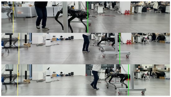
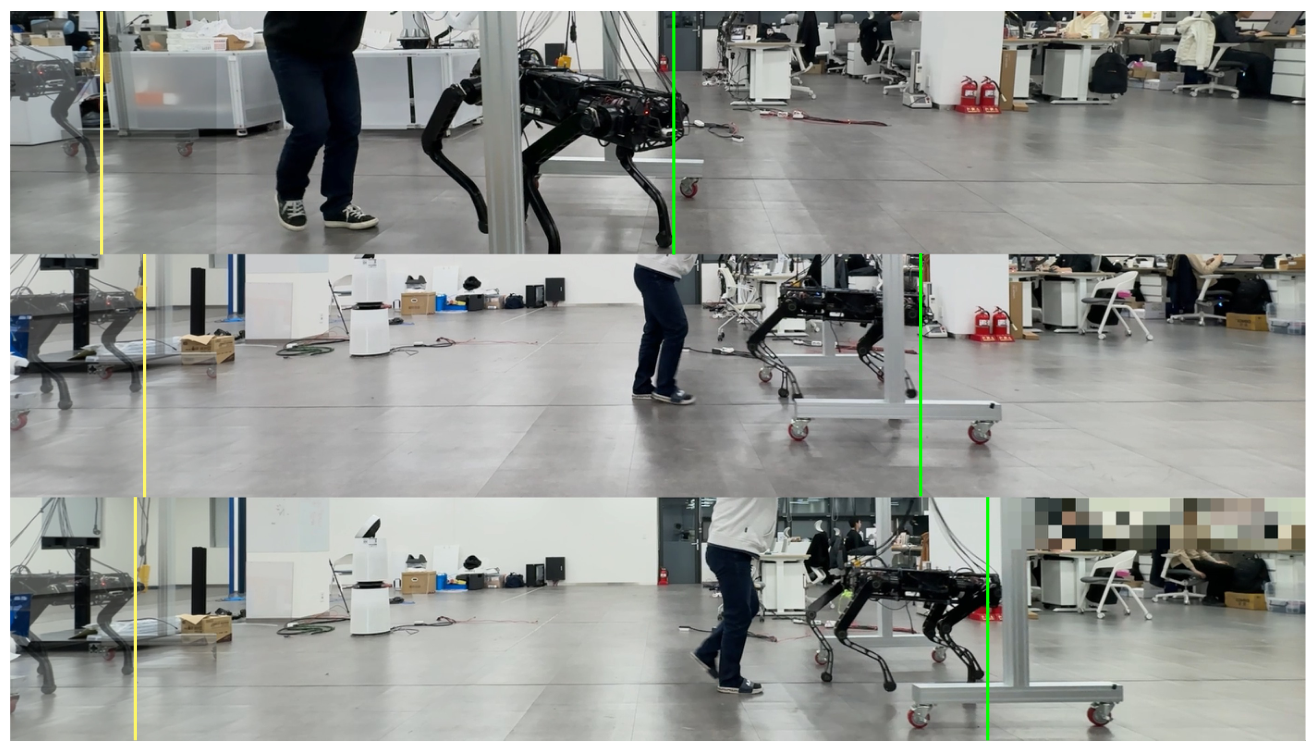
- We demonstrate on a 55 kg quadruped driven by custom high-reduction actuators built from off-the-shelf motors that this extension enables stable zero-shot sim-to-real locomotion without base- or controller-level randomization, and we isolate its effect by comparing against PACE and a domain-randomization baseline (Figure 1).
- We show that the augmented parameter set remains physically identifiable despite its higher dimensionality—the identified friction characteristic is recovered consistently across independent optimization runs—and that its advantage persists on a trajectory not used for identification, indicating that the added terms capture a physical effect that generalizes beyond the identification trajectory rather than additional fitting freedom.
Figure 1.
Comparison of velocity tracking performance among three models under 1.0 m/s command: (Top) Baseline, (Middle) PACE, and (Bottom) Ours. In each panel, the yellow and green vertical lines indicate the starting position and the final position after 5 s of locomotion, respectively, measured at the front-most foot.
2. Materials and Methods
The primary objective of this paper is to achieve zero-shot sim-to-real transfer for a quadruped robot equipped with high-gear-ratio actuation systems, ensuring that policies trained in simulation deploy to the real world without additional fine tuning. To this end, this section details the methodology, comprising extended actuator modeling based on real-world robot data, a parameter identification process utilizing evolutionary algorithms, and the subsequent policy training via reinforcement learning using the identified parameters.
2.1. Extended Friction Modeling
Simulators commonly used in reinforcement learning research, such as MuJoCo [20] and Isaac Gym [21], primarily adopt the Coulomb–Viscous friction model for numerical efficiency. This model can be formulated as follows.
where is the friction torque, and and denote the Viscous and Coulomb friction coefficients, respectively, with units of and .
While this simplified formulation facilitates ease of computation, it characterizes friction as a monotonically increasing function of velocity once motion initiates. Consequently, it fails to distinguish between static and dynamic friction and cannot capture the nonlinear friction drop observed at low velocities, which is a behavior known as the Stribeck effect [22].
In systems with low reduction ratios, static friction tends to contribute a smaller fraction of the overall joint dynamics, so its effect on the sim-to-real gap is often limited. In high-reduction systems, however, the friction and reflected inertia amplified by the gear ratio make static friction a far more significant factor. Consequently, relying on a simplified model fails to ensure fidelity between simulation and the physical robot, acting as a critical factor that widens the sim-to-real gap. To address this, we employ an extended friction model that incorporates the Stribeck effect as follows:
where is the Stribeck friction coefficient (), denotes the Stribeck velocity defining the affected velocity range (), and represents the curvature of the transition (dimensionless).
At exactly zero velocity, the viscous term vanishes trivially because it is proportional to . The Coulomb and Stribeck terms vanish as well, since by convention. The model therefore exerts no friction torque at ; friction acts only once motion begins, which is consistent with the model’s memoryless, velocity-dependent formulation rather than an explicit static/stiction regime.
Dynamic friction models such as LuGre [23] introduce an internal state that additionally captures pre-sliding displacement and hysteresis. In the locomotion regime considered here, however, the dominant sim-to-real discrepancy stems from the low-velocity friction drop, which the memoryless Stribeck term already captures; we therefore avoid the per-joint state integration and its numerical-stability burden across large-scale parallel training that a dynamic friction model would require.
2.2. Single Joint Dynamics
Following the approach used in PACE, we assume that the current control loop operates at a sufficiently high frequency and accounts for the saturation nonlinearities inherent in the commanded torque. Based on these assumptions, the single-joint dynamics, incorporating the proposed friction model, is formulated as follows.
where represents the effective joint inertia ()—the reflected rotor (armature) inertia combined with the link inertia. and are the proportional and derivative gains of the PD controller, respectively, while is the target joint position and is the joint bias. The friction term incorporates the previously described extended friction model, which accounts for the Stribeck effect.
To refine these parameters, we define the optimization vector by extending the parameter set from PACE as follows:
where represents the global time delay applied uniformly to all joints, and n denotes the number of joints. Consequently, the vector consists of n-dimensional sub-vectors for each physical parameter along with a single scalar for the global delay.
2.3. Actuator Modeling
To minimize the sim-to-real gap, we incorporate the physical characteristics of the brushless DC (BLDC) motors and the overall drive system into our simulation, following the approaches established in previous studies [24,25]. Specifically, our model is designed to account for the nonlinear properties of the motor’s torque constant and the output saturation resulting from the voltage and current constraints of the motor driver. First, the target joint torque calculated by the PD controller is converted into the motor frame using the gear ratio. The required current is then determined by dividing this motor torque by the motor constant , and the effective motor current is obtained by applying a clipping function based on the maximum allowable current .
Next, to account for electrical constraints, the target voltage is computed. We calculate the effective voltage using the motor resistance R and the Back Electromotive Force (Back EMF) voltage derived from the motor speed and the velocity constant . The sum of these voltages is then clipped by the bus voltage .
Finally, the resulting effective motor torque is converted back into the joint torque to be applied to the system.
2.4. Parameter Optimization
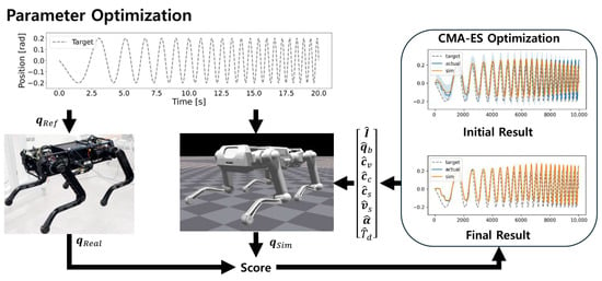
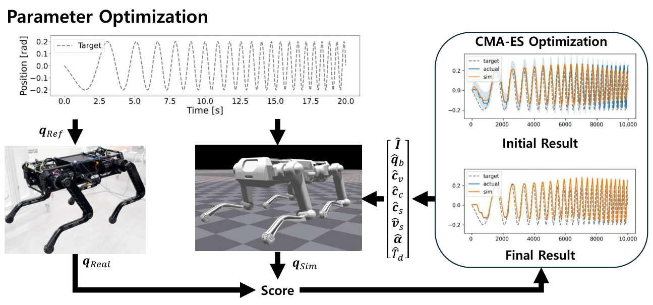
In this paper, the Covariance Matrix Adaptation Evolutionary Strategy (CMA-ES) [26] is employed to optimize the defined parameter set . To address the discrete nature of the global time delay (), which must be determined as an integer multiple of the simulation time step, we adopted an algorithm variant specifically optimized for mixed-integer optimization [27] along with its corresponding open-source library [28]. The overall parameter-optimization pipeline is illustrated in Figure 2. Owing to its gradient-free evolutionary search mechanism, CMA-ES is well suited to the high-dimensional search space of this study and converged stably in our experiments.
Figure 2.
Overview of the CMA-ES-based parameter optimization pipeline for actuator system identification. A chirp reference trajectory is applied identically to the physical robot and the simulation. The resulting joint trajectories, and , are compared to compute a score (the joint-tracking error), which CMA-ES minimizes by iteratively updating the physical parameter set . The right panels show the simulated response before (Initial Result) and after (Final Result) optimization, illustrating convergence toward the measured trajectory.
Following the experimental procedure described for PACE, we collected data by suspending the robot in the air to isolate joint dynamics. A chirp signal, with a frequency continuously sweeping from 0.1 to 2 Hz, was applied as a reference input to all joints in both the physical robot and the simulation. To align the simulated behavior with the real-world response, we employed the Mean Squared Error (MSE) as the loss function to minimize the discrepancy between the joint angles.
This optimization was conducted simultaneously across all joints of the quadruped robot. The process was implemented within Isaac Gym, leveraging its massive parallelism to run 1024 robot agents in parallel. This approach allowed us to efficiently process vast amounts of trajectory data and accelerate the convergence of the parameter identification.
2.5. Reinforcement Learning
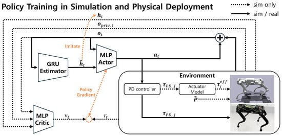
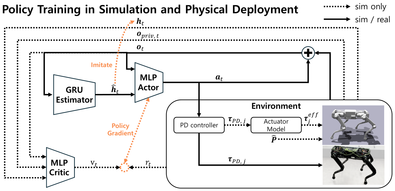
In this paper, we formulate the locomotion task as an infinite-horizon Partially Observable Markov Decision Process (POMDP), which is defined by the tuple . An overview of the policy-training and deployment framework is shown in Figure 3.
Figure 3.
Overall diagram for reinforcement learning policy training and real-world robot deployment. The estimator network is trained via supervised learning to predict the terrain height around the robot, taking observations—excluding the user’s velocity commands—as input. The action output from the actor calculates the required torque through the identical PD controller in both simulation and the real robot. In the real robot, the calculated torque is used as is, while in the simulation, processed torque through the actuator model is used, and the parameters derived through the optimization process are applied.
Here, the state space , action space , and observation space are continuous. represents the initial state distribution, denotes the transition probability, is the reward function, and is the discount factor.
At each time step t, the learning agent determines an action based on the current observation through its policy and receives a reward from the environment. The objective of the agent is to find an optimal policy that maximizes the expected cumulative discounted reward, . To achieve this, we employ the Proximal Policy Optimization (PPO) algorithm [29], which has demonstrated robust performance in high-dimensional continuous action spaces across various robotic locomotion studies [3,5,7,30].
2.6. Implementation Detail
In conventional reinforcement learning research for robotic control, domain/dynamics randomization is widely utilized to bridge the gap. In contrast, this paper directly applies the physical parameters identified through the evolutionary algorithm without randomizing the base or controller parameters; only a standard ground-friction randomization and periodic push perturbations—applied to all models—are used, as summarized in Table 1. By leveraging high-fidelity identified parameters, we achieved direct sim-to-real transfer to the physical robot. This approach suggests that precise actuator and friction modeling can reduce reliance on extensive randomization, which may otherwise lead to overly conservative policies.
Table 1.
Domain randomization and perturbation settings used during policy training. Ground friction and external push are applied to all models, whereas base mass, center-of-mass offset, and PD gains are randomized only for the DR policy.
2.6.1. Observation and Action
The observation vector consists of the base linear velocity , angular velocity , projected gravity , velocity commands , joint positions and velocities , and the previous action .
The action represents the target joint positions. Following previous works [16,31], the action is added to the nominal standing pose to facilitate efficient learning during the initial stages, resulting in the final desired joint position .
where k is a scaling factor, which is set to 0.5 in this paper.
The desired joint position generated by the actor is then converted into the target joint torque through a PD controller. In the simulation, this torque is processed through the actuator model described in Section 2.3 to derive the effective joint torque . In contrast, on the physical robot, the computed is applied directly to the motor drivers.
Identical PD gains were employed across the simulation, the physical robot, and the CMA-ES-based parameter optimization process with a proportional gain (P) of and a derivative gain (D) of .
2.6.2. Network Architecture
For policy training, we utilize the Asymmetric Actor–Critic architecture [32]. Both the actor and critic are composed of Multi-Layer Perceptrons (MLPs) with hidden layer sizes of [512, 256, 128], using the Exponential Linear Unit (ELU) as the activation function. The actor takes the observation and the estimated local terrain information —provided by an estimator network—to output the action . The critic additionally utilizes privileged information , which includes the swing and contact times of the feet (), ground reaction forces , and the ground truth terrain heights surrounding the feet. Following previous studies [31,33], an estimator network is trained concurrently to infer local terrain heights. We employ a Gated Recurrent Unit (GRU) [34] for the estimator to effectively process temporal sequences with a relatively small number of parameters. This network receives proprioceptive information from (excluding velocity commands) as input to estimate the heights around the robot’s feet. During the training phase, the estimator network is optimized via supervised learning to minimize the MSE between the ground truth obtained from the simulator and the estimated height .
2.6.3. Rewards
Following the reward structures proposed in previous work [31], the total reward function is formulated as . The positive reward component comprises terms for velocity tracking, air time, and body height. The negative component is designed to penalize excessive movements and foot slippage as well as provide the necessary regularization for successful sim-to-real transfer, including penalties for action rates, joint velocities, joint accelerations, and torque magnitudes. For a more detailed description of the reward function, please refer to [31].
3. Results
3.1. Hardware
The quadruped robot used in our experiments weighs 55 kg and features a total of 12 joints with each leg consisting of three joints: Hip Abduction–Adduction (HAA), Hip Flexion–Extension (HFE), and Knee Flexion–Extension (KFE). The legs are designated as Left Back (LB), Left Front (LF), Right Back (RB), and Right Front (RF). The robot is equipped with an onboard PC and an Inertial Measurement Unit (IMU). Each joint integrates a planetary gear reducer with a reduction ratio over 40:1 as well as absolute and incremental encoders. Communication between the onboard PC and the motor drives is established via an EtherCAT interface. The maximum output torque of each joint is approximately with a maximum joint velocity of .
3.2. Compared Methods
To evaluate the proposed method, we compare four sim-to-real transfer strategies:
- Baseline: This model utilizes the mass and inertia properties of the links derived from CAD data without any optimization or friction modeling.
- DR: This policy is trained with domain randomization following common practice in RL-based legged locomotion [16], using the settings summarized in Table 1 and without identifying the actuator parameters.
- PACE: This is the system-identification pipeline of [19], which optimizes the effective joint inertia, joint offsets, the global time delay, and a Coulomb–Viscous friction model.
- Ours: Our method extends the PACE pipeline by augmenting its friction model with the Stribeck friction terms introduced in this paper.
Both PACE and Ours optimize the same set of physical quantities—the effective joint inertia, joint offsets, the global time delay, and the Coulomb–Viscous friction coefficients—while Ours additionally optimizes the Stribeck parameters, and the parameter values are identified independently for each model. In contrast, neither the Baseline nor the DR policy undergoes system identification: the Baseline appears in the identification results (Table 2) only as the unoptimized reference, whereas the DR policy is evaluated solely through the real-world comparison (Table 3).
Table 2.
CMA-ES based system identification result. Scores for PACE and Ours are reported as mean ± std over four independent CMA-ES seeds.
Table 3.
Comparison of model performance in simulation and real environments. Values are reported as mean ± std—over three training seeds (25 episodes per seed) for simulation and over five trials for the real world—using the RMSE for the tracking error. The 0.3 m/s command uses a step profile; the 1.0 m/s command uses a ramp profile (2 s acceleration followed by 3 s at constant velocity) over the same 5 s trial, for which the time-averaged velocity of a perfectly tracked command is 0.8 m/s, not 1.0 m/s.
3.3. System Identification
The CMA-ES-based parameter optimization was executed in Isaac Gym, where 1024 robot agents operated in parallel to collect trajectory data. The optimization process was configured to terminate if the improvement in the objective function fell below 0.01% of the average of the preceding 40 iterations.
Each parameter was bounded per joint—damping , effective joint inertia , offset , Coulomb friction , Stribeck friction , Stribeck velocity , and Stribeck curvature —with a single global bound time steps for the delay. All parameters were rescaled to for optimization; the initial mean was sampled uniformly within this normalized range, the initial covariance was set to the identity matrix, and the initial step size was .
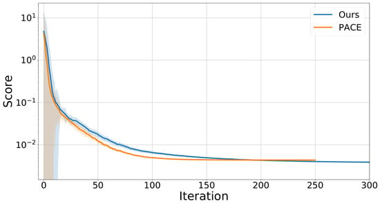
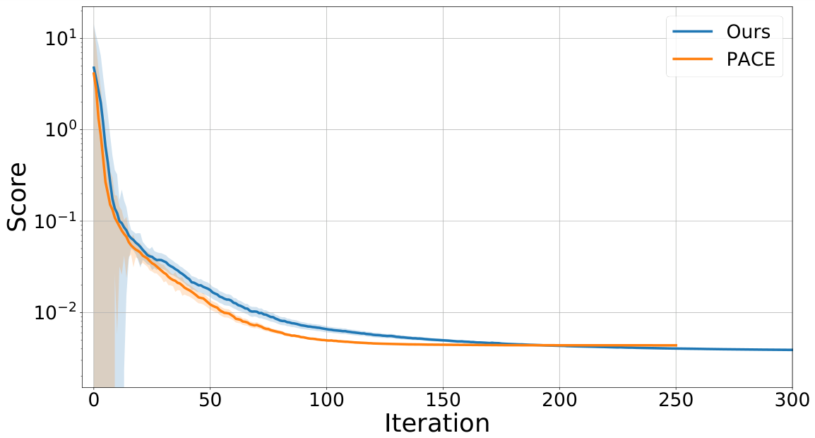
When following the reference trajectory used for optimization, the Baseline recorded a score of 0.190. In contrast, both PACE and our method, which utilized optimized physical parameters, achieved significantly lower scores. Across four independent seeds, PACE converged to a score of and our method to a lower (mean ± std; Table 2). As illustrated in Figure 4, both models converge stably, and our method attains a lower final objective despite its higher-dimensional search space.
Figure 4.
CMA-ES optimization results for the two friction models. The x-axis is the optimization iteration and the y-axis the objective score on a logarithmic scale. Each curve is the lowest-loss run among four seeds for that model, and the shaded region is the std of the CMA-ES population at each iteration (one band per model; darker shading indicates where the two bands overlap); the final scores, averaged over the four seeds, are given in Table 2.
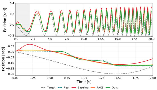
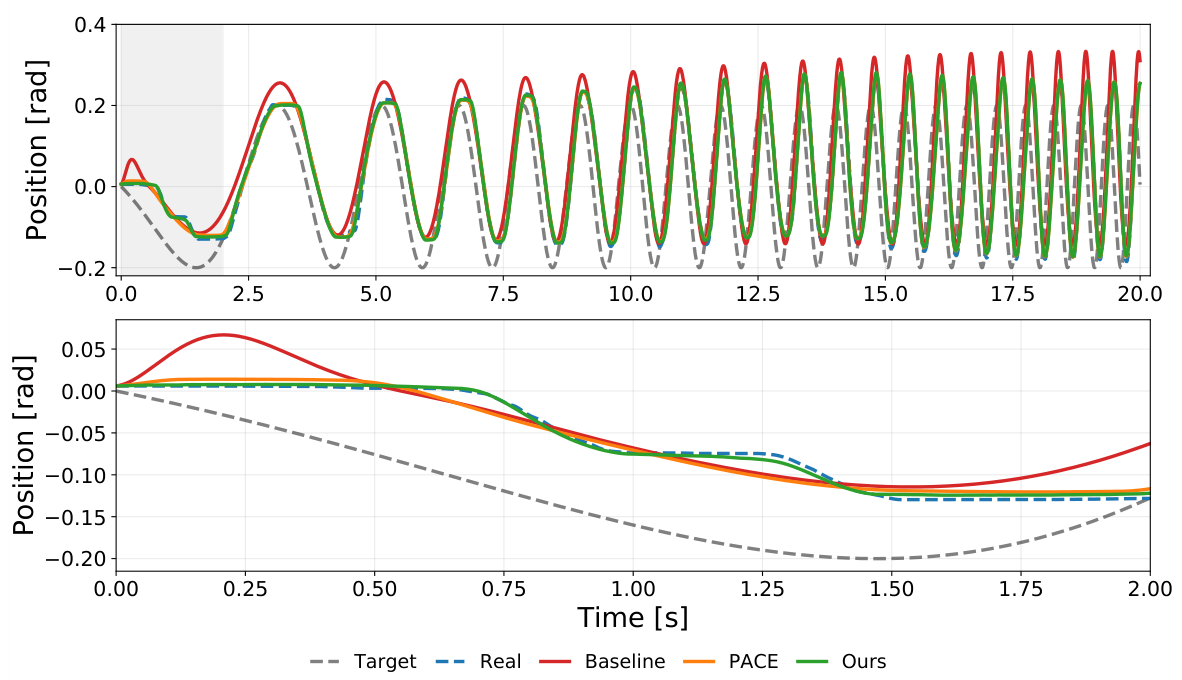
As indicated by the results in Table 2, a substantial discrepancy exists between the unoptimized Baseline and the two optimized models. This finding underscores that purely kinematic or CAD-based models in high-reduction gear systems pose a significant challenge to bridging the sim-to-real gap. It suggests that comprehensive system identification—encompassing inertia, offsets, and delays alongside accurate friction modeling—is important for successful sim-to-real transfer. Comparing the two optimized models, the proposed extended friction model achieves an additional 16% lower identification loss than the conventional friction model, which is aggregated over the chirp trajectory across all 12 joints. Because this aggregate is averaged over the whole chirp, including higher-speed segments where the Stribeck term contributes little, it understates the benefit at low velocity; the trajectory data of Figure 5, for a single representative joint (LB HAA), makes this concentration visible. Over the full trajectory, the joint-position tracking error, measured as the root mean square error (RMSE), decreases from 0.045 rad for the Baseline to 0.0095 rad for PACE and 0.0087 rad for our method; within the 0–2 s low-velocity phase, however, the benefit of the Stribeck term is far more pronounced with RMSE values of 0.0275, 0.0117, and 0.0039 rad for the Baseline, PACE, and our method, respectively—a 67% reduction of our method relative to PACE. In this phase, our method reproduces the Stribeck-type friction behavior at low velocity characteristic of high-reduction actuators, which the conventional Coulomb–Viscous model cannot represent. These results demonstrate the benefit of incorporating the Stribeck effect for high-fidelity motion replication in high-gear-ratio legged systems.
Figure 5.
Trajectory tracking of the LB HAA joint on the chirp reference trajectory used for parameter identification. The top panel shows the full sequence and the bottom panel zooms into the initial low-velocity phase (0–2 s); the gray shaded region in the top panel marks this 0–2 s interval that is magnified in the bottom panel. Our method, incorporating the Stribeck term, matches the real trajectory more closely than the Baseline and PACE.
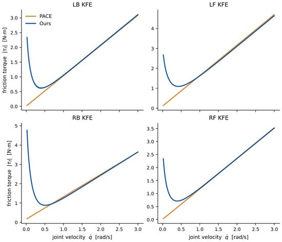
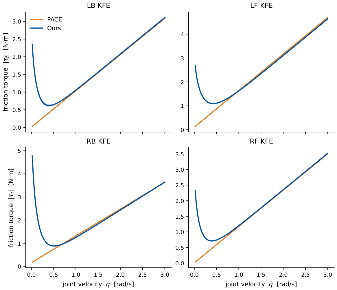
To confirm that these gains do not stem from the larger parameter set or from optimizer randomness, we repeated the identification with four independent CMA-ES seeds for each model. Both models converged with negligible seed variability—the identification-loss coefficient of variation was 0.34% for our method and 0.12% for PACE—and the 16% identification-loss improvement held across all seeds. The effective joint inertia, offset, and delay parameters were uniquely identified in both models (coefficient of variation below 1%; the global delay was time steps). Adding the Stribeck term did introduce a redundancy in how the low-velocity friction is partitioned between the Coulomb and Stribeck components (Coulomb coefficient of variation ), yet the resulting friction torque was identified to within 0.6% across seeds: the coefficient scatter reflects reparametrization within a flat direction of the loss landscape rather than a failure to identify the friction characteristic. Figure 6 shows this for the four knee (KFE) joints—the across-seed spread is too narrow to be visible, while our model captures the low-velocity friction that the Coulomb–Viscous model cannot represent.
Figure 6.
Identified friction torque for the four knee (KFE) joints, one per leg. Solid lines denote the mean over four independent CMA-ES seeds and shaded bands the std across seeds; this std is at most N·m, so the bands are narrower than the line width over most of the velocity range, indicating that the friction characteristic is identified consistently regardless of the seed. Ours captures the low-velocity friction drop that PACE cannot represent.
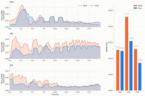
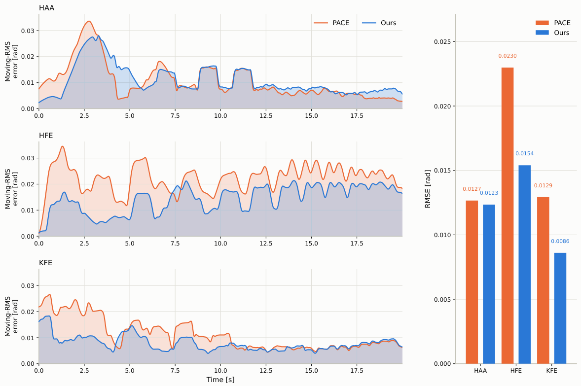
To confirm that the identified parameters generalize beyond the identification data rather than overfitting it, we evaluated both models on an unseen trajectory that was not used for identification: a simultaneous three-joint chirp on the RF leg sweeping 0.05–1.0 Hz at the identification amplitude over 20 s. We replayed this trajectory in each identified simulation and compared the resulting joint positions against the real robot. Our method attained a lower tracking RMSE on all three actuated joints (Figure 7): 0.0123 vs. 0.0127 rad at HAA, 0.0154 vs. 0.0230 rad at HFE, and 0.0086 vs. 0.0129 rad at KFE (Ours vs. PACE), which is a 33% reduction at both the HFE and KFE joints. That the improvement persists on this unseen trajectory—rather than shrinking or inverting, as overfitting to the identification data would produce—indicates that the Stribeck extension captures a physical effect that generalizes beyond the identification trajectory rather than absorbing additional degrees of freedom.
Figure 7.
Simulation tracking error on an unseen RF-leg chirp (0.05–1.0 Hz, 20 s) that was not used for identification. Left: per-joint tracking error (simulation minus real robot) smoothed by a 1.0 s moving-RMS window for visualization; PACE in orange, Ours in blue. Right: the corresponding unsmoothed RMSE over the full trajectory. Ours yields the lower error at the HFE and KFE joints throughout the trajectory, and it is at parity or slightly better at HAA.
3.4. Flat Terrain
The policy was trained in Isaac Gym using 4096 parallel robot agents over 3000 iterations. Utilizing the PPO algorithm implemented in RSL-RL [35], the training process took approximately 1.5 h on a single NVIDIA RTX A5000 GPU (NVIDIA Corporation, Santa Clara, CA, USA). The trained policy was deployed on a quadruped robot, AiDIN-VIII from AIDIN ROBOTICS Inc. (Anyang, Republic of Korea) [36]. The robot’s base orientation, angular velocity, and joint states (positions and velocities) were acquired through the onboard IMU and joint encoders. The base linear velocity was estimated using a state estimator based on the framework presented in [37]. The policy inference was executed on the onboard PC at a frequency of 50 Hz, while the communication between the PC and the motor drives was maintained at 1 kHz via the EtherCAT interface. The policy is stepped at 50 Hz in simulation as well, matching the on-robot control rate, and the command-to-actuation latency of the drive system is reproduced by the identified global delay , which is applied to the commanded torque and remains active during both system identification and policy training. The policy-loop rate and the drive latency are therefore explicitly represented in simulation.
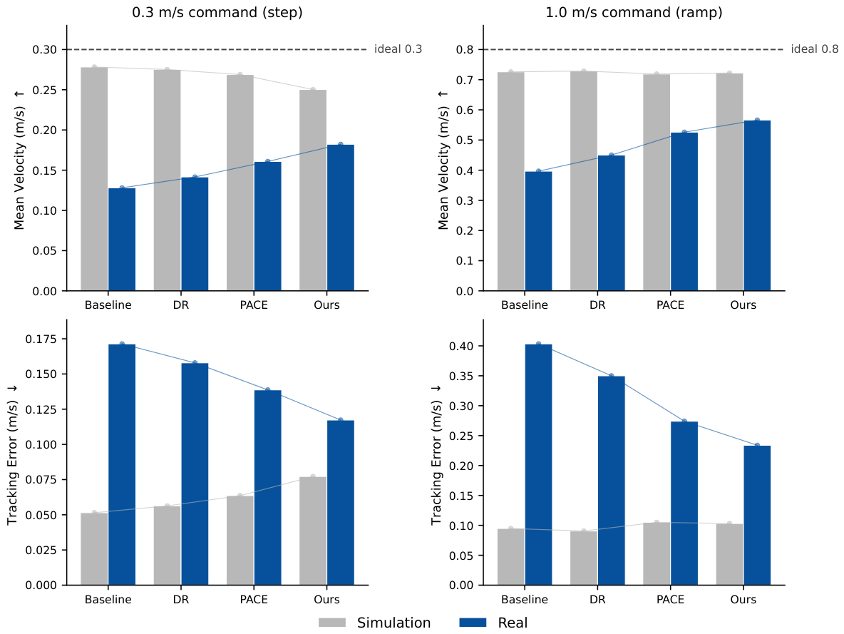
We trained each of the four models with the same reward function and evaluated velocity tracking in both simulation and the real world using the mean velocity and the velocity tracking error (RMSE), as summarized in Table 3. In simulation, all four models tracked the velocity commands well; the decisive differences emerge only after transfer to the real robot.
On the physical robot, however, the models diverged markedly. At both velocity commands of 0.3 m/s and 1.0 m/s, the policy trained with our method consistently outperformed the other models, whereas the Baseline model showed the most significant degradation. Specifically, the Baseline model experienced a mean velocity reduction of 54.0% at the low (0.3 m/s) and 45.3% at the high (1.0 m/s) velocity command in the real-world environment compared to the simulation. Furthermore, the baseline policy failed to maintain a straight forward trajectory, exhibiting significant directional instability. This behavioral discrepancy, where the robot deviates from the commanded path, can be clearly observed in Video S1. Figure 1 illustrates the resulting difference in forward displacement among the three models after five seconds of locomotion under the 1.0 m/s command. The DR policy reduced this degradation partially with mean-velocity drops of 48.5% and 38.2% at the low- and high-velocity commands. In the case of PACE, the average velocity decreased by 40.2% at low speeds and 26.8% at high speeds. While PACE reduced the sim-to-real gap more effectively than the Baseline and DR, these results highlight its limitations in accurately capturing friction dynamics during low-velocity joint movements. In contrast, our method exhibited a velocity reduction of 27.2% for the low-speed command and 21.6% for the high-speed command. These quantitative results confirm that our method, which incorporates Stribeck friction modeling, bridges the sim-to-real gap more effectively than PACE and DR at both commands; the corresponding improvement in the sim-to-real ratio relative to PACE is quantified below.
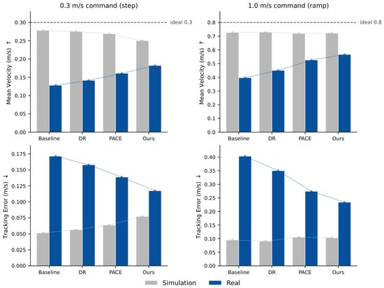
These results indicate that across both commands, identifying the actuator dynamics narrows the sim-to-real gap more effectively than randomizing base- and controller-level parameters. In absolute terms, our method attains the best real-world tracking at both commands—the lowest tracking error and the highest mean velocity (Table 3, Figure 8). In simulation, by contrast, our method shows a slightly higher tracking error than PACE: because its identified simulation includes the additional Stribeck friction, the simulated actuator is more resistive, so the same policy tracks marginally worse in simulation while transferring more faithfully to the real robot.
Figure 8.
Simulation versus real-world performance for each model, in mean velocity (top) and tracking error (bottom) at the 0.3 m/s (left) and 1.0 m/s (right) commands. The arrows in the axis labels indicate the preferred direction of each metric: ↑ denotes that a higher value is better and ↓ that a lower value is better. Gray bars denote simulation and blue bars the real robot; the gap between the two bars indicates the sim-to-real discrepancy (smaller is better), and the dashed lines mark the time-averaged velocity of a perfectly tracked command over the full trial (0.3 m/s for the step profile; 0.8 m/s for the 1.0 m/s ramp profile). Bars show the mean values from Table 3, which reports the corresponding std values.
As a complementary measure of fidelity—distinct from absolute performance—we define the sim-to-real ratio, for each metric, as the real-robot value divided by its simulation value, so that a value closer to 1 indicates a smaller sim-to-real gap, and we quantify each model’s improvement as the magnitude of the relative change of this ratio with respect to the Baseline, which is averaged over both commands. Relative to the Baseline, PACE improved the sim-to-real ratio, averaged over both commands, by 32.0% for mean velocity and 36.6% for tracking error, whereas our method achieved larger average improvements of 50.8% and 50.5%, respectively. In contrast, the DR policy improved these ratios, on average, by 12.4% and 12.5%, respectively, indicating that the widely used practice of randomizing base and controller parameters leaves the actuator-dynamics discrepancy that dominates high-reduction systems unaddressed. Because this ratio reflects agreement rather than task performance, we report it alongside the absolute values above, where our method is best on both.
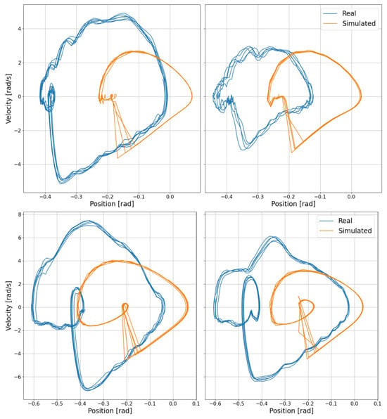
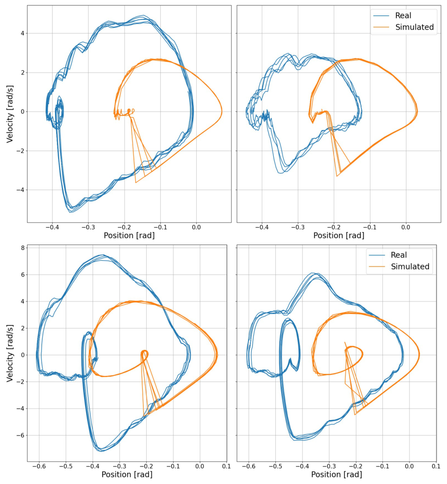
To evaluate the high-fidelity correspondence between the simulation and the physical robot, we analyzed the phase portraits of the joint dynamics for the two identified models (PACE and Ours) under velocity commands of 0.3 m/s and 1.0 m/s, as illustrated in Figure 9. For a quantitative assessment of the similarity between these phase-space trajectories, we employed Dynamic Time Warping (DTW) [38], which is a robust metric for measuring the distance between time-series data. The DTW distances, summarized in Table 4, reveal that our method, which incorporates Stribeck friction, consistently recorded lower values—indicating higher similarity—in both low-speed and high-speed regimes. At 1.0 m/s, the reduction is smaller (5.9%), as expected: at higher joint speeds, viscous and inertial terms dominate and the low-velocity Stribeck regime is traversed only briefly, so the two models largely agree. The gap widens sharply at 0.3 m/s, where the Stribeck effect is most pronounced and the DTW distance drops by approximately 42% relative to the model without Stribeck friction. This reduction highlights the benefit of incorporating the Stribeck effect when modeling actuators with high reduction ratios to bridge the sim-to-real gap. The observed offsets in joint positions are attributed to the structural self-weight of the robot body. Since the parameter identification in this paper was conducted with the robot suspended in the air, the static offsets caused by the robot’s weight under ground contact conditions are considered outside the scope of this paper.
Figure 9.
Comparison of phase portraits for the LB KFE joint under different velocity commands and identified models. The top and bottom rows correspond to velocity commands of 0.3 m/s and 1.0 m/s, respectively. The left columns show the results using PACE, while the right columns show the results using our method.
Table 4.
Phase portrait comparison using DTW distances between simulation and real-world walking trajectories.
3.5. Rough Terrain
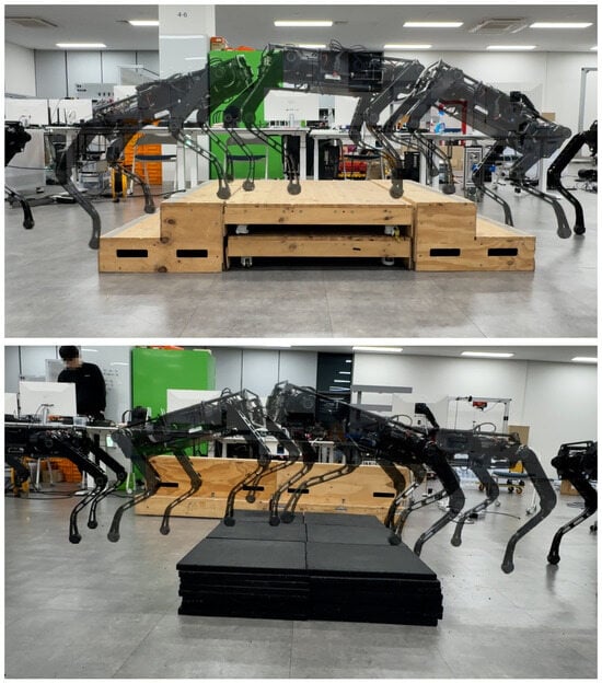
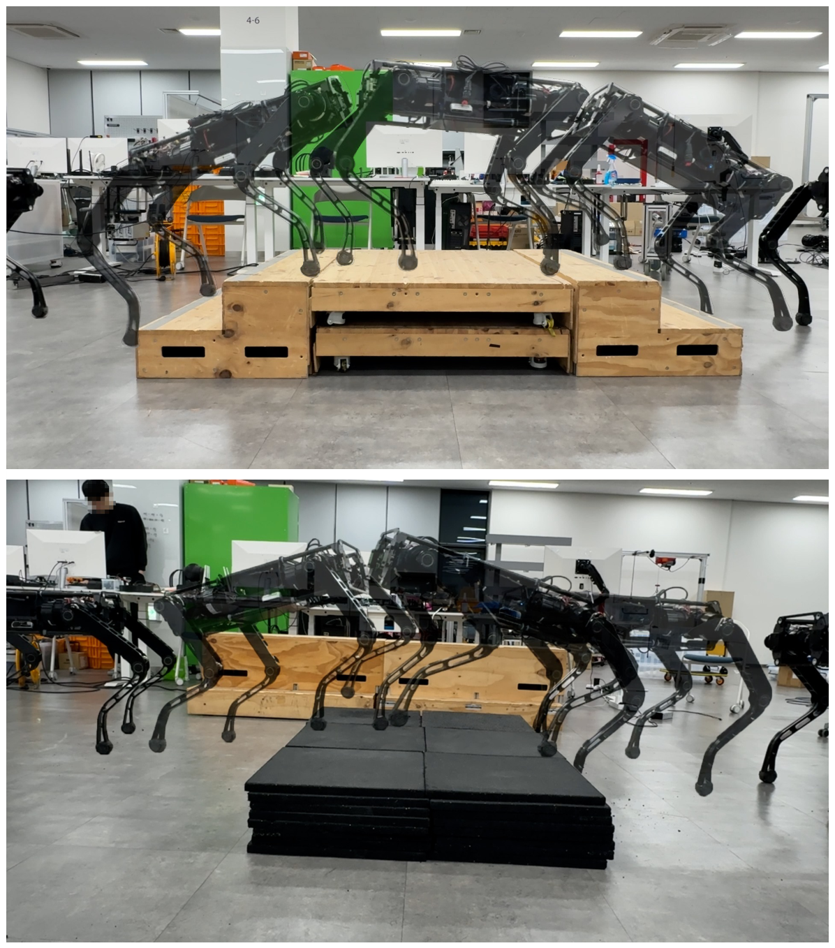
The policy for navigating rough terrain was trained in Isaac Gym with 4096 parallel agents over 10,000 iterations, which took approximately six hours. To overcome the challenges of unstructured environments without the aid of exteroceptive sensors (e.g., cameras or LiDAR), we implemented a GRU-based state estimator utilizing only proprioceptive sensor data. This estimator reconstructs local terrain information, such as the height of the ground around the feet, allowing the robot to adapt to irregular surfaces. As a result, the robot successfully traversed a variety of challenging terrains, including a 20 cm step, stairs, and uneven terrain, as shown in Figure 10.
Figure 10.
Locomotion performance on various rough terrains. (Top) The robot traversing up and down stairs. (Bottom) Successful crossing of a 20 cm high step obstacle.
4. Discussion
Building on the PACE system-identification pipeline, this paper extended its actuator friction model with a Stribeck term to achieve high-fidelity zero-shot sim-to-real transfer for a quadruped robot driven by high-gear-ratio actuators.
Our experiments indicate that identifying the actuator dynamics narrows the sim-to-real gap more than randomizing base- and controller-level parameters does. Relative to the unoptimized Baseline, our method improved the sim-to-real ratio by 50.8% in mean velocity and 50.5% in tracking error, and PACE improved it by 32.0% and 36.6%, whereas a conventional domain randomization policy—perturbing base- and controller-level parameters—improved these ratios by 12.4% and 12.5%. This gap arises because such randomization does not capture the actuator dynamics that dominate high-reduction systems. We emphasize that this comparison concerns a domain-randomization policy that perturbs base- and controller-level parameters; we did not evaluate a randomization that directly perturbs actuator-level quantities such as friction, motor-torque scaling, or latency. Such a scheme could also reduce the actuator-dynamics gap, but it requires specifying plausible ranges for these quantities a priori—the heuristic burden that system identification removes, since identified parameters would themselves be needed to center such ranges. We therefore regard actuator-level randomization and identification as complementary rather than competing, and we restrict our claim to the finding that a common base- and controller-level randomization leaves the dominant actuator-dynamics gap largely unaddressed on our platform. The advantage of our method over PACE widens at low velocity: at 0.3 m/s, it improves the sim-to-real ratios by 58.2% (mean velocity) and 54.3% (tracking error), versus 30.0% and 34.5% for PACE, whereas at 1.0 m/s, the margin narrows to 43.5% versus 34.0% (mean velocity) and 46.7% versus 38.7% (tracking error). This indicates that the Stribeck-type friction behavior at low velocity represented by our method—but not by the conventional Coulomb–Viscous model—is the principal factor distinguishing our method from PACE. Beyond flat-ground tracking, the same identified parameters supported more demanding locomotion: using a policy trained on rough terrain, the robot climbed and descended stairs and overcame individual steps of up to 20 cm in height, relying solely on proprioceptive sensing.
While robots can overcome certain obstacles like steps through physical interaction, traversing environments with gaps or limited footholds necessitates precise environmental perception and foot placement. Therefore, we plan to extend this research by integrating exteroceptive sensors and incorporating local terrain information into the reinforcement learning framework. This will lead to the development of advanced controllers capable of navigating a broader range of complex and unstructured environments. Finally, our evaluation is conducted on a single high-gear-ratio platform; validation across additional platforms is left to future work.
Supplementary Materials
The following supporting information can be downloaded at: https://www.mdpi.com/article/10.3390/machines14091031/s1, Video S1: Extended actuator dynamics identification and zero-shot sim-to-real locomotion of the AiDIN-VIII quadruped. The video shows the acquisition of real-world chirp data from the suspended robot, the CMA-ES-based parameter optimization in Isaac Gym, the resulting joint-tracking comparison of the Baseline, PACE, and the proposed model, the real-world velocity-tracking comparison of the three policies under a 1.0 m/s command, and the traversal of stairs and high steps together with recovery from foot entrapment.
Author Contributions
Conceptualization, H.K. and H.R.C.; methodology, H.K. and H.R.C.; software, H.K., H.L. and J.P.; validation, H.K., B.Y. and S.N.; formal analysis, H.K. and S.N.; investigation, H.K., Y.S., B.Y. and J.O.; resources, H.L. and J.P.; data curation, H.K., J.O. and B.Y.; writing—original draft preparation, H.K.; writing—review and editing, H.K., H.Y. and H.R.C.; visualization, H.K.; supervision, H.Y. and H.R.C.; project administration, H.R.C. All authors have read and agreed to the published version of the manuscript.
Funding
This work was supported by the Technology Innovation Program Development Program-System semiconductor commercialization design (2410017886) funded By the Ministry of Trade, Industry & Energy (MOTIE, Korea).
Data Availability Statement
Data are contained within the paper.
Conflicts of Interest
Mr. Hyunyong Lee and Mr. Jiman Park are employees of AIDIN ROBOTICS Inc. Although the company had no input into the experimental design, interpretation of findings, or the decision to publish, the authors may benefit from the commercialization of the technology discussed in this research should it become applicable.
References
- Jenelten, F.; Grandia, R.; Farshidian, F.; Hutter, M. TAMOLS: Terrain-aware motion optimization for legged systems. IEEE Trans. Robot. 2022, 38, 3395–3413. [Google Scholar] [CrossRef] [Scilit]
- Khazoom, C.; Hong, S.; Chignoli, M.; Stanger-Jones, E.; Kim, S. Tailoring solution accuracy for fast whole-body model predictive control of legged robots. IEEE Robot. Autom. Lett. 2024, 9, 11074–11081. [Google Scholar] [CrossRef] [Scilit]
- Lee, M.; Kim, H.; Kim, J.T.; Park, S.; Lee, J.H.; Cho, J.; Hwangbo, J. Learning Quadrupedal Locomotion for a Heavy Hydraulic Robot Using an Actuator Model. IEEE Robot. Autom. Lett. 2025, 10, 12421–12428. [Google Scholar] [CrossRef] [Scilit]
- Kim, Y.; Oh, H.; Lee, J.; Choi, J.; Ji, G.; Jung, M.; Youm, D.; Hwangbo, J. Not only rewards but also constraints: Applications on legged robot locomotion. IEEE Trans. Robot. 2024, 40, 2984–3003. [Google Scholar] [CrossRef] [Scilit]
- Kang, D.; Kim, G.; Choe, J.; Kim, H.; Park, H.W. Learning Impact-Rich Rotational Maneuvers via Centroidal Velocity Rewards and Sim-to-Real Techniques: A One-Leg Hopper Flip Case Study. In Proceedings of the 9th Conference on Robot Learning; Lim, J., Song, S., Park, H.W., Eds.; PMLR: Cambridge, MA, USA, 2025; Volume 305, pp. 2329–2343. [Google Scholar]
- Hwangbo, J.; Lee, J.; Dosovitskiy, A.; Bellicoso, D.; Tsounis, V.; Koltun, V.; Hutter, M. Learning agile and dynamic motor skills for legged robots. Sci. Robot. 2019, 4, eaau5872. [Google Scholar] [CrossRef] [Scilit] [PubMed]
- Rudin, N.; Hoeller, D.; Reist, P.; Hutter, M. Learning to walk in minutes using massively parallel deep reinforcement learning. In Proceedings of the Conference on Robot Learning; PMLR: Cambridge, MA, USA, 2022; pp. 91–100. [Google Scholar]
- Fey, N.; Margolis, G.B.; Peticco, M.; Agrawal, P. Bridging the Sim-to-Real Gap for Athletic Loco-Manipulation. In Proceedings of the 7th Robot Learning Workshop: Towards Robots with Human-Level Abilities, Singapore, 27 April 2025. [Google Scholar]
- Rudin, N.; Hoeller, D.; Bjelonic, M.; Hutter, M. Advanced skills by learning locomotion and local navigation end-to-end. In Proceedings of the 2022 IEEE/RSJ International Conference on Intelligent Robots and Systems (IROS); IEEE: Piscataway, NJ, USA, 2022; pp. 2497–2503. [Google Scholar]
- Xie, Z.; Da, X.; Van de Panne, M.; Babich, B.; Garg, A. Dynamics randomization revisited: A case study for quadrupedal locomotion. In Proceedings of the 2021 IEEE International Conference on Robotics and Automation (ICRA); IEEE: Piscataway, NJ, USA, 2021; pp. 4955–4961. [Google Scholar]
- Tan, J.; Xie, Z.; Boots, B.; Liu, C.K. Simulation-based design of dynamic controllers for humanoid balancing. In Proceedings of the 2016 IEEE/RSJ International Conference on Intelligent Robots and Systems (IROS); IEEE: Piscataway, NJ, USA, 2016; pp. 2729–2736. [Google Scholar]
- Yu, W.; Kumar, V.C.; Turk, G.; Liu, C.K. Sim-to-real transfer for biped locomotion. In Proceedings of the 2019 IEEE/RSJ International Conference on Intelligent Robots and Systems (IROS); IEEE: Piscataway, NJ, USA, 2019; pp. 3503–3510. [Google Scholar]
- Miller, A.; Yu, F.; Brauckmann, M.; Farshidian, F. High-performance reinforcement learning on spot: Optimizing simulation parameters with distributional measures. In Proceedings of the 2025 IEEE International Conference on Robotics and Automation (ICRA); IEEE: Piscataway, NJ, USA, 2025; pp. 9981–9988. [Google Scholar]
- Seok, S.; Wang, A.; Chuah, M.Y.; Otten, D.; Lang, J.; Kim, S. Design principles for highly efficient quadrupeds and implementation on the MIT Cheetah robot. In Proceedings of the 2013 IEEE International Conference on Robotics and Automation; IEEE: Piscataway, NJ, USA, 2013; pp. 3307–3312. [Google Scholar]
- Ha, S.; Lee, J.; van de Panne, M.; Xie, Z.; Yu, W.; Khadiv, M. Learning-based legged locomotion: State of the art and future perspectives. Int. J. Robot. Res. 2025, 44, 1396–1427. [Google Scholar] [CrossRef] [Scilit]
- Nahrendra, I.M.A.; Yu, B.; Myung, H. DreamWaQ: Learning robust quadrupedal locomotion with implicit terrain imagination via deep reinforcement learning. In Proceedings of the 2023 IEEE International Conference on Robotics and Automation (ICRA); IEEE: Piscataway, NJ, USA, 2023; pp. 5078–5084. [Google Scholar]
- Kumar, A.; Fu, Z.; Pathak, D.; Malik, J. RMA: Rapid Motor Adaptation for Legged Robots. In Robotics: Science and Systems XVII; RSS Foundation, 2021. [Google Scholar]
- Shin, Y.H.; Hong, S.; Woo, S.; Choe, J.; Son, H.; Kim, G.; Kim, J.H.; Lee, K.; Hwangbo, J.; Park, H.W. Design of KAIST HOUND, a quadruped robot platform for fast and efficient locomotion with mixed-integer nonlinear optimization of a gear train. In Proceedings of the 2022 International Conference on Robotics and Automation (ICRA); IEEE: Piscataway, NJ, USA, 2022; pp. 6614–6620. [Google Scholar]
- Bjelonic, F.; Tischhauser, F.; Hutter, M. Towards bridging the gap: Systematic sim-to-real transfer for diverse legged robots. Int. J. Robot. Res. 2026, 02783649261459628. [Google Scholar] [CrossRef] [Scilit]
- Todorov, E.; Erez, T.; Tassa, Y. Mujoco: A physics engine for model-based control. In Proceedings of the 2012 IEEE/RSJ International Conference on Intelligent Robots and Systems; IEEE: Piscataway, NJ, USA, 2012; pp. 5026–5033. [Google Scholar]
- Makoviychuk, V.; Wawrzyniak, L.; Guo, Y.; Lu, M.; Storey, K.; Macklin, M.; Hoeller, D.; Rudin, N.; Allshire, A.; Handa, A.; et al. Isaac Gym: High Performance GPU-Based Physics Simulation For Robot Learning. In Proceedings of the Thirty-Fifth Conference on Neural Information Processing Systems Datasets and Benchmarks Track, Virtual, 14 December 2021. [Google Scholar]
- Pennestrì, E.; Rossi, V.; Salvini, P.; Valentini, P.P. Review and comparison of dry friction force models. Nonlinear Dyn. 2016, 83, 1785–1801. [Google Scholar] [CrossRef] [Scilit]
- Canudas de Wit, C.; Olsson, H.; Åström, K.J.; Lischinsky, P. A new model for control of systems with friction. IEEE Trans. Autom. Control 1995, 40, 419–425. [Google Scholar] [CrossRef] [Scilit]
- Tan, J.; Zhang, T.; Coumans, E.; Iscen, A.; Bai, Y.; Hafner, D.; Bohez, S.; Vanhoucke, V. Sim-to-Real: Learning Agile Locomotion For Quadruped Robots. In Proceedings of the Robotics: Science and Systems, Pittsburgh, PA, USA, 26–30 June 2018. [Google Scholar]
- Shin, Y.H.; Song, T.G.; Ji, G.; Park, H.W. Reinforcement Learning for High-Speed Quadrupedal Locomotion with Motor Operating Region Constraints: Mitigating Motor Model Discrepancies through Torque Clipping in Realistic Motor Operating Region. IEEE Robot. Autom. Mag. 2024, 32, 49–59. [Google Scholar] [CrossRef] [Scilit]
- Hansen, N.; Müller, S.D.; Koumoutsakos, P. Reducing the time complexity of the derandomized evolution strategy with covariance matrix adaptation (CMA-ES). Evol. Comput. 2003, 11, 1–18. [Google Scholar] [CrossRef] [Scilit] [PubMed]
- Hamano, R.; Saito, S.; Nomura, M.; Shirakawa, S. CMA-ES with margin: Lower-bounding marginal probability for mixed-integer black-box optimization. In Proceedings of the Genetic and Evolutionary Computation Conference, Boston, MA, USA, 9–13 July 2022; pp. 639–647. [Google Scholar]
- Nomura, M.; Shibata, M. cmaes: A simple yet practical python library for cma-es. arXiv 2024, arXiv:2402.01373. [Google Scholar]
- Schulman, J.; Wolski, F.; Dhariwal, P.; Radford, A.; Klimov, O. Proximal policy optimization algorithms. arXiv 2017, arXiv:1707.06347. [Google Scholar]
- Kang, H.S.; Lee, H.Y.; Park, J.M.; Nam, S.W.; Son, Y.W.; Yi, B.S.; Oh, J.Y.; Song, J.H.; Choi, S.Y.; Kim, B.G.; et al. ARS: Ai-driven recovery controller for quadruped robot using single-network model. Biomimetics 2024, 9, 749. [Google Scholar] [CrossRef] [Scilit] [PubMed]
- Ji, G.; Mun, J.; Kim, H.; Hwangbo, J. Concurrent training of a control policy and a state estimator for dynamic and robust legged locomotion. IEEE Robot. Autom. Lett. 2022, 7, 4630–4637. [Google Scholar] [CrossRef] [Scilit]
- Pinto, L.; Andrychowicz, M.; Welinder, P.; Zaremba, W.; Abbeel, P. Asymmetric Actor Critic for Image-Based Robot Learning. In Robotics: Science and Systems XIV; RSS Foundation: Sydney, Australia, 2018. [Google Scholar]
- Kim, G.; Lee, Y.H.; Park, H.W. A learning framework for diverse legged robot locomotion using barrier-based style rewards. In Proceedings of the 2025 IEEE International Conference on Robotics and Automation (ICRA); IEEE: Piscataway, NJ, USA, 2025; pp. 10004–10010. [Google Scholar]
- Chung, J.; Gulcehre, C.; Cho, K.; Bengio, Y. Empirical evaluation of gated recurrent neural networks on sequence modeling. arXiv 2014, arXiv:1412.3555. [Google Scholar]
- Schwarke, C.; Mittal, M.; Rudin, N.; Hoeller, D.; Hutter, M. Rsl-rl: A learning library for robotics research. arXiv 2025, arXiv:2509.10771. [Google Scholar]
- AIDIN Robotics. Available online: https://www.aidinrobotics.co.kr (accessed on 26 August 2026).
- Camurri, M.; Ramezani, M.; Nobili, S.; Fallon, M. Pronto: A multi-sensor state estimator for legged robots in real-world scenarios. Front. Robot. AI 2020, 7, 68. [Google Scholar] [CrossRef] [Scilit] [PubMed]
- Senin, P. Dynamic Time Warping Algorithm Review; Information and Computer Science Department, University of Hawaii: Manoa, HI, USA, 2008; Volume 855, p. 40. [Google Scholar]

Disclaimer/Publisher’s Note: The statements, opinions and data contained in all publications are solely those of the individual author(s) and contributor(s) and not of MDPI and/or the editor(s). MDPI and/or the editor(s) disclaim responsibility for any injury to people or property resulting from any ideas, methods, instructions or products referred to in the content. |
© 2026 by the authors. Licensee MDPI, Basel, Switzerland. This article is an open access article distributed under the terms and conditions of the Creative Commons Attribution (CC BY) license.