


Abstract
Terrain-induced chassis motion can disturb the soil-entry attitude and soil engagement of seeding components on compact agricultural robots. This study develops an inverted 2RPU–RPS rallel mechanism for a maize seeding robot to regulate the end effector without levelling the entire chassis. The mechanism supports the disc opener and terminal seed tube and provides one vertical translation and two rotations. A nonlinear inverse-kinematic model, a unilateral penetration–downforce model, constrained electric-cylinder dynamics, and a coordinated feedforward–PI controller are established. The roll and pitch loops combine chassis-attitude feedforward compensation with end-effector error feedback, while the vertical loop regulates the opener downforce using a stiffness-based penetration reference and force feedback. MATLAB/Simulink simulations are conducted under isolated attitude disturbances, vertical terrain excitation, and multi-row operation. With maximum chassis roll and pitch disturbances of 4.49° and 3.35°, the end-effector RMSE values are 0.109° and 0.114°, respectively. At a prescribed downforce of 400 N, the downforce RMSE is 11.07 N and the mean disc-opener penetration is 34.99 mm. During the 300 s multi-row simulation, the mean penetration remains 34.96 mm and the downforce RMSE is 12.65 N. The results indicate that the strategy can attenuate chassis-induced disturbances and maintain stable soil engagement under the adopted modelling assumptions.
1. Introduction
Maize is one of the principal cereal crops in China and also serves as an important raw material for animal feed and industrial processing. Sowing is the first operation in maize production, and its quality has a direct influence on seed germination, seedling uniformity, population establishment, and subsequent yield formation [1,2]. Precision sowing requires not only reliable single-seed metering at the prescribed spacing but also accurate placement of seeds at an appropriate depth and with a relatively consistent orientation. Shallow placement may expose seeds to inadequate soil moisture, insufficient covering, and pronounced temperature fluctuations, thereby reducing germination and impairing emergence uniformity. Excessive sowing depth, in contrast, increases the mechanical resistance encountered by emerging seedlings, delays emergence, and may lead to weak seedlings, missing plants, or discontinuous stands [1,2,3,4,5]. In oriented seed placement, the posture of the terminal seed tube also affects the trajectory and final position of the seed after discharge. Maintaining stable penetration of the disc opener, a consistent terminal seed-tube orientation, and uniform sowing depth is therefore essential for improving the operational quality of maize seeding [1,2,4,5].
Conventional maize planters are commonly operated as tractor-drawn implements. Their row units generally employ parallel four-bar linkages, gauge wheels, and spring-loading devices to follow variations in the soil surface [6,7]. Considerable research has been devoted to the structural optimization of planter row units and soil-engaging components. Row cleaners, furrow openers, and related components have been investigated through field experiments and discrete-element simulations [8,9]. Improvements in four-bar linkage geometry, spring-loading configurations, and hydraulic or electrohydraulic actuators have enhanced terrain-following performance and reduced sowing-depth variation. Existing studies have also demonstrated the close relationship between opener downforce and soil penetration. Mechanical downforce selection, integrated depth–compaction regulation, PLC-based furrow-depth control, and sensor-based coulter-depth regulation have all been investigated to improve the consistency of soil engagement [10,11,12,13]. Electrohydraulic actuation, automatic downforce evaluation, operating-speed analysis, downforce-feedback regulation, and terrain-slope compensation have further improved the responsiveness of active depth-control systems [14,15,16,17,18,19]. Appropriate downforce regulation can mitigate the effects of changes in soil mechanical properties and surface elevation on sowing depth. Most of these investigations, however, treat the row unit primarily as a vertically moving profiling mechanism. Even when hydraulic or electrohydraulic actuators are introduced for active regulation, the controlled motion is generally concentrated in the vertical direction to regulate penetration depth or downforce. Consequently, such systems have limited capability to compensate for roll and pitch disturbances of the seeding end effector, which may affect the soil-entry attitude of the disc opener and the orientation of the terminal seed tube [6,7,11,12,13,14,15,16,17,18,19].
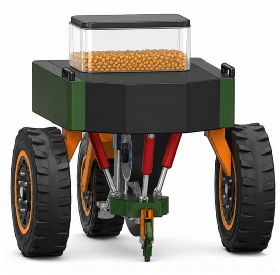
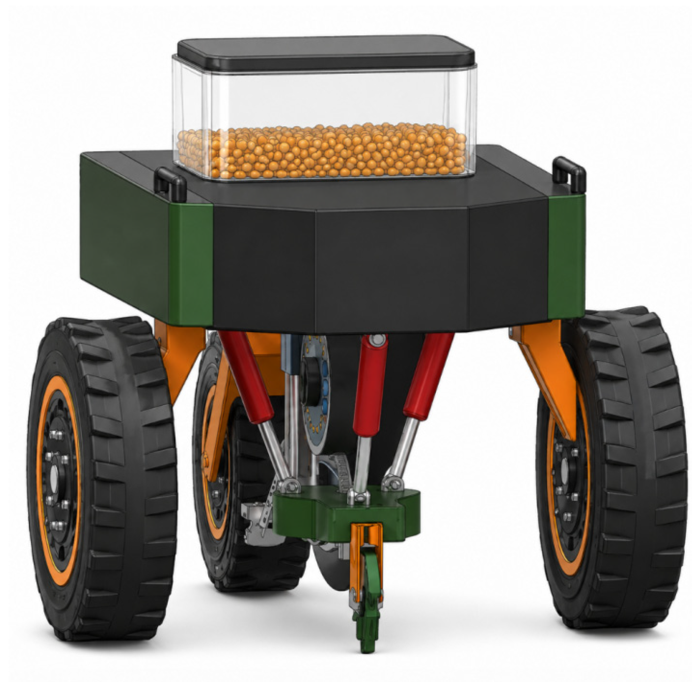
With the continuing development of intelligent agricultural machinery and unmanned field operations, compact and lightweight seeding robots have attracted growing interest as alternative platforms for precision planting [20,21]. As illustrated in Figure 1, these robots offer compact structures, small turning radii, and improved maneuverability in fragmented fields. However, their reduced mass, wheel track, and wheelbase make them more susceptible to terrain-induced roll, pitch, and vertical disturbances [22]. These disturbances can alter disc-opener penetration and terminal seed-tube orientation, resulting in unstable sowing depth and seed-placement deviation. Consequently, passive vertical profiling alone may be insufficient to address the combined effects of chassis-attitude variation and local terrain undulation [14,18].
Figure 1.
Conceptual diagram of the maize seeding robot.
Chassis-levelling systems have been investigated to improve the attitude stability of agricultural vehicles operating on uneven terrain [22,23]. Although such systems can reduce overall vehicle inclination, they must actuate the chassis together with its upper-mounted components, resulting in increased driven mass and greater structural and control complexity. Moreover, chassis levelling does not fully eliminate relative motion between the seeding unit and the local soil surface. Active planter downforce systems based on hydraulic or electrohydraulic actuation have been developed to regulate row-unit force and vertical position [11,12,13,14,15,16,17,18,19]. Compared with passive spring-loaded mechanisms, these systems provide adjustable downforce and improved response to changes in terrain or soil support. However, their controlled motion is generally restricted to the vertical direction. When the chassis undergoes roll or pitch disturbances, the disc opener and terminal seed tube may therefore remain inclined with the vehicle body even when the vertical downforce is regulated. Consequently, the unresolved problem is not merely the control of penetration or downforce, but the simultaneous regulation of soil engagement and end-effector attitude.
Parallel mechanisms are characterized by relatively high structural stiffness, favourable load-carrying capacity, low moving inertia, and limited accumulation of positioning errors. These properties make them suitable for pose adjustment within a restricted workspace. Compared with general six-degree-of-freedom parallel mechanisms, lower-mobility architectures can constrain motions unnecessary for the assigned task and thereby reduce mechanical and control complexity [24,25]. A 2RPU–RPS parallel mechanism consists of two RPU limbs and one RPS limb and can be configured to provide one translational and two rotational degrees of freedom [26]. Recent studies have also investigated the kinematic and dynamic modelling, pose-error compensation, disturbance rejection, and real-time control of lower-mobility parallel platforms [27,28,29,30,31]. However, the task-oriented application of such mechanisms to maize seeding remains insufficiently explored, particularly for coordinated regulation of end-effector attitude, opener penetration, and downforce under chassis disturbances. By coordinating the three actuated limbs, the moving platform provides the roll, pitch, and vertical motions required for seeding-end adjustment. In the proposed inverted arrangement, the robot chassis serves as the fixed platform, while the disc opener and terminal seed tube are mounted on the lower moving platform. This configuration enables direct regulation of the seeding components without actuating the entire chassis and extends conventional four-bar profiling beyond vertical adjustment alone.
To address the coupled attitude deviation and soil-engagement fluctuation of compact maize seeding robots operating on uneven terrain, this study applies an inverted 2RPU–RPS parallel mechanism between the robot chassis and the seeding end effector. The contribution of this work is not the proposal of a new 1T2R topology, but the task-oriented use of this lower-mobility mechanism to extend conventional vertical depth/downforce regulation to coordinated regulation of soil engagement and end-effector attitude. Compared with passive or actively actuated four-bar depth-control systems, which mainly regulate vertical penetration or downforce, the proposed mechanism provides one vertical translation and two rotational degrees of freedom, allowing penetration/downforce regulation together with roll and pitch compensation of the disc opener and terminal seed tube. Different from existing lower-mobility parallel-mechanism studies that mainly address mechanism design, kinematics, and general pose control, the present work establishes a maize seeding-oriented framework that couples nonlinear kinematics, electric-cylinder dynamics, offset disc–soil-contact modelling, and coordinated attitude–downforce control. To better represent field operation, the simulation framework further incorporates spatially heterogeneous soil parameters, with stiffness and damping varying across successive soil regions, to evaluate the robustness of the proposed downforce-control strategy to local soil-property variations.
The remainder of this paper is organized as follows. Section 2 analyzes the adjustment requirements of the maize seeding end effector. Section 3 presents the mechanical design, mobility characteristics, and comparison with the conventional ground-following mechanism. Section 4 establishes the nonlinear kinematic and disc–soil-contact models. Section 5 develops the coordinated attitude and downforce-control model. Section 6 describes the simulation framework, parameter settings, and operating scenarios. Section 7 presents and discusses the simulation results, and Section 8 summarizes the main conclusions and limitations of this study.
2. Analysis of End-Effector Attitude-Adjustment Requirements
2.1. Effects of Field-Surface Disturbances on the Seeding End Effector
The operating environment of a maize seeding robot generally contains surface undulations, spatial variations in soil mechanical properties, and interference from crop residues. As the robot travels over such terrain, continuous changes in wheel–ground contact generate disturbances in the chassis attitude. Because compact seeding robots have smaller dimensions and lower mass than large tractor–implement systems, they possess less resistance to terrain-induced disturbances. A given difference in surface elevation may therefore produce a more pronounced chassis-attitude response. Previous investigations have shown that vehicle configuration and terrain inclination can significantly affect the stability of lightweight agricultural platforms [22,23].
As shown in Figure 2, the effects of chassis disturbances on the seeding end effector can be divided into three principal categories. First, chassis roll causes the disc opener to incline laterally, which may produce an oblique seed furrow. The seed-tube outlet is displaced laterally at the same time, potentially causing seeds to deviate from the furrow centerline. Second, chassis pitch alters the soil-entry angle of the disc opener. Variations in pitch also change the relative position between the seed-tube outlet and the seedbed, thereby modifying the trajectory of a seed after it leaves the tube. Third, vertical chassis motion directly changes the actual soil penetration of the disc opener. Fluctuating penetration results in variable seeding depth and may consequently impair germination and emergence uniformity.
Figure 2.
Degrees of freedom for end-effector pose adjustment of the maize seeding robot.
Accordingly, the design of the attitude-adjustment mechanism must simultaneously account for the soil-entry attitude of the disc opener, the orientation of the terminal seed tube, and the opener penetration depth. Restricting the mechanism to a single vertical ground-following motion is insufficient.
2.2. End-Effector Attitude-Adjustment Objectives
Based on the kinematic requirements of the seeding operation, roll, pitch, and vertical displacement are selected as the primary controllable degrees of freedom. Let the vertical displacement of the moving platform be , the roll angle be , and the pitch angle be . The platform pose variables can then be expressed as
where represents the overall vertical movement of the end effector, describes its lateral inclination, and describes its longitudinal pitching motion. Ideally, the roll and pitch angles of the seeding end effector should remain close to zero, while the disc-opener penetration should approach its prescribed target value.
Let denote the chassis roll angle and the compensatory roll angle generated by the mechanism. The roll angle of the end effector relative to the ground is
Similarly, if is the chassis pitch angle and is the compensatory pitch angle, the resulting end-effector pitch angle is
The attitude-adjustment mechanism must therefore generate a compensatory rotation opposite to the direction of the chassis disturbance.
3. Design of the Inverted 2RPU–RPS End-Effector Attitude-Adjustment Mechanism
3.1. Overall Structural Configuration
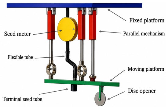
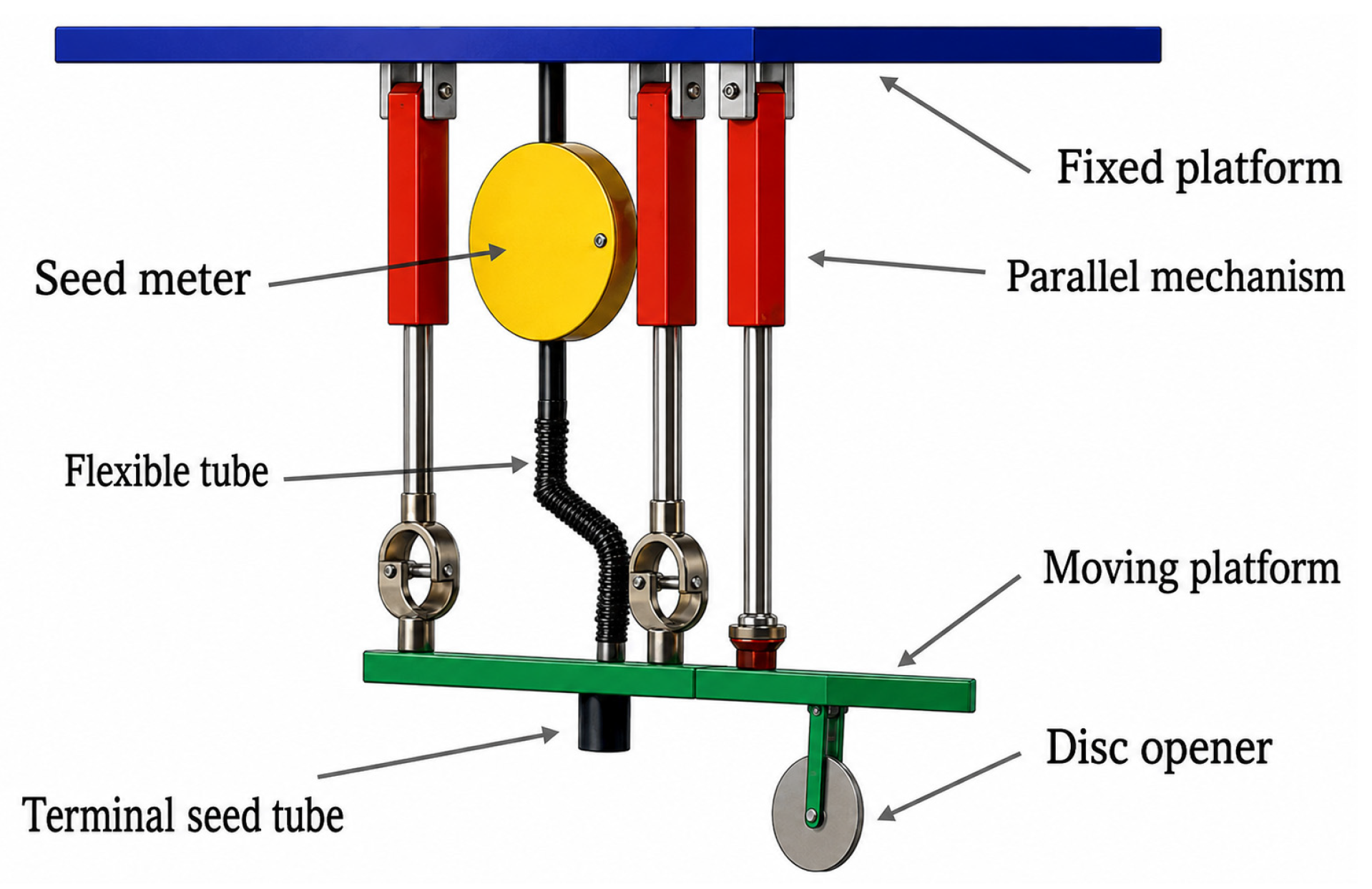
As illustrated in Figure 3, the proposed inverted 2RPU–RPS mechanism consists primarily of a fixed platform, a moving platform, two RPU limbs, one RPS limb, three electric cylinders, a disc opener, a terminal seed tube, a flexible delivery tube, and the associated connectors. The fixed platform is designed to be mounted beneath the chassis of the maize seeding robot. The moving platform is designed to be positioned below the fixed platform and to carry the disc opener and terminal seed tube, which are the principal soil-engaging and seed-delivery components.
Figure 3.
Structural configuration of the parallel attitude-adjustment system.
The seed-metering device is designed to be installed on the upper structure and connected to the terminal seed tube through a flexible delivery tube. Metered seeds are conveyed through the flexible tube to the terminal seed tube and subsequently deposited in the furrow formed by the disc opener. In the proposed inverted arrangement, the fixed platform is designed to be rigidly connected beneath the chassis, whereas the moving platform is positioned below it to support the seeding end-effector components.
The moving-platform pose is regulated through coordinated extension and retraction of the three actuated limbs. The front limb adopts an RPS configuration, whereas the rear-left and rear-right limbs adopt RPU configurations. For the prescribed joint arrangement, longitudinal and lateral translations of the moving platform and rotation about the vertical axis are constrained. The retained task motions are vertical translation, roll, and pitch, corresponding to a 1T2R motion pattern commonly considered in lower-mobility parallel-mechanism design [24,25,26].
Approximately equal extension or retraction of the three limbs produces vertical motion. Opposite length variations in the two rear RPU limbs generate roll compensation, whereas differential motion between the front RPS limb and the two rear limbs produces pitch compensation. These motion characteristics are formally examined through the mobility and constraint analysis in Section 3.2.
3.2. Mobility and Constraint Analysis
Under the ideal assumptions of rigid links, negligible joint clearance, and accurately aligned joint axes, the instantaneous motion of the moving platform relative to the fixed platform can be represented by the twist vector
where , , and denote the translational velocities along the , , and axes, respectively, and , , and denote the corresponding angular velocities about these axes.
For the prescribed T-shaped limb arrangement, the closed-loop constraints generated by the two RPU limbs and the RPS limb restrict the longitudinal translation, lateral translation, and yaw rotation of the moving platform. At the task-space level, the independent constraints can be expressed as
where
Equation (5) gives
Because the three constraint equations are mutually independent,
The mobility of the moving platform is therefore
Accordingly, the allowable instantaneous motion of the moving platform can be expressed as
The mechanism therefore exhibits one translational and two rotational degrees of freedom, corresponding to vertical translation along the -axis, roll rotation about the -axis, and pitch rotation about the -axis. The retained task-space coordinates are consequently written as
and the resulting motion pattern is denoted as .
The three retained degrees of freedom perform different functions in the seeding operation. The vertical displacement () changes the relative height between the disc opener and the soil surface and is therefore used to regulate opener penetration and soil reaction. The roll angle () compensates for lateral chassis inclination and reduces the lateral inclination of the disc opener and terminal seed tube. The pitch angle () compensates for longitudinal chassis inclination and adjusts the soil-entry attitude of the disc opener.
Although , , and are independent task-space coordinates, their relationships with the three actuator-length variations are not globally independent. Let
denote the length rates of the front RPS limb, rear-left RPU limb, and rear-right RPU limb, respectively. At the nominal symmetric configuration, the differential relationship between the actuator-length rates and the moving-platform velocity can be written as
The three basic motion modes can therefore be separated as
and
Equations (14)–(16) confirm that vertical translation, roll rotation, and pitch rotation are generated by coordinated extension of the three limbs, differential motion between the two rear RPU limbs, and differential motion between the front RPS limb and the rear limbs, respectively. These relationships are consistent with the operating principle described above.
The three actuated prismatic joints provide three independent input variables corresponding to the three controllable task-space coordinates. The mechanism is therefore nonredundantly actuated. Nevertheless, a single actuator does not correspond exclusively to one platform degree of freedom. A prescribed pure vertical, roll, or pitch motion generally requires coordinated displacement of multiple actuators.
The motion modes described by Equations (14)–(16) are approximately decoupled only near the nominal symmetric configuration. At finite roll and pitch angles, the coefficients relating the actuator-length variations to , , and vary with the instantaneous platform pose. Consequently, nonlinear translation–rotation coupling exists among the retained motions. This coupling is preserved in the complete nonlinear inverse-kinematic model established in Section 4.1 and in the pose-dependent Jacobian formulation presented in Section 4.2, rather than being neglected through a constant linear mapping. The nominal differential relationship used here is consistent with the reduced Jacobian subsequently adopted for singularity analysis.
In addition, the disc–soil contact point is offset from the centre of the moving platform. Therefore, roll and pitch rotations of the moving platform also induce translational displacement of the contact point. This rotation-induced displacement does not constitute an additional degree of freedom of the mechanism; it is a rigid-body geometric effect associated with the existing rotational degrees of freedom. The corresponding coupling between platform attitude, contact-point height, opener penetration, and downforce is considered through the complete contact-point transformation established in Section 4.3.
Under the ideal kinematic assumptions adopted in this study, longitudinal translation, lateral translation, and yaw rotation are excluded from the task space. Parasitic motion in these constrained directions is therefore not included in the present simulation model. In a physical prototype, joint clearance, joint-axis misalignment, link deformation, and assembly errors may introduce small parasitic displacements. These effects will be examined through detailed multibody simulation and experimental prototype validation in future work.
3.3. Comparison with a Conventional Four-Bar Ground-Following Mechanism
Conventional planter row units commonly employ parallel four-bar linkages to provide reliable passive vertical ground following. Although these mechanisms are structurally simple and suitable for conventional tractor-drawn planters, they cannot actively compensate for roll or pitch disturbances, and their downforce response is influenced by spring stiffness and passive structural delay. In contrast, the electric-cylinder-driven 2RPU–RPS mechanism coordinates vertical translation, roll, and pitch, thereby enabling direct regulation of both end-effector attitude and soil engagement. A quantitative baseline comparison between the proposed active regulation system and a conventional mechanically spring-loaded ground-following system is presented in Section 7.2.
4. Kinematic and Soil-Engagement Models
4.1. Inverse Kinematics of the Inverted 2RPU–RPS Parallel Mechanism
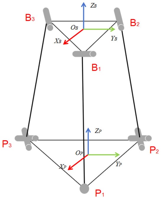
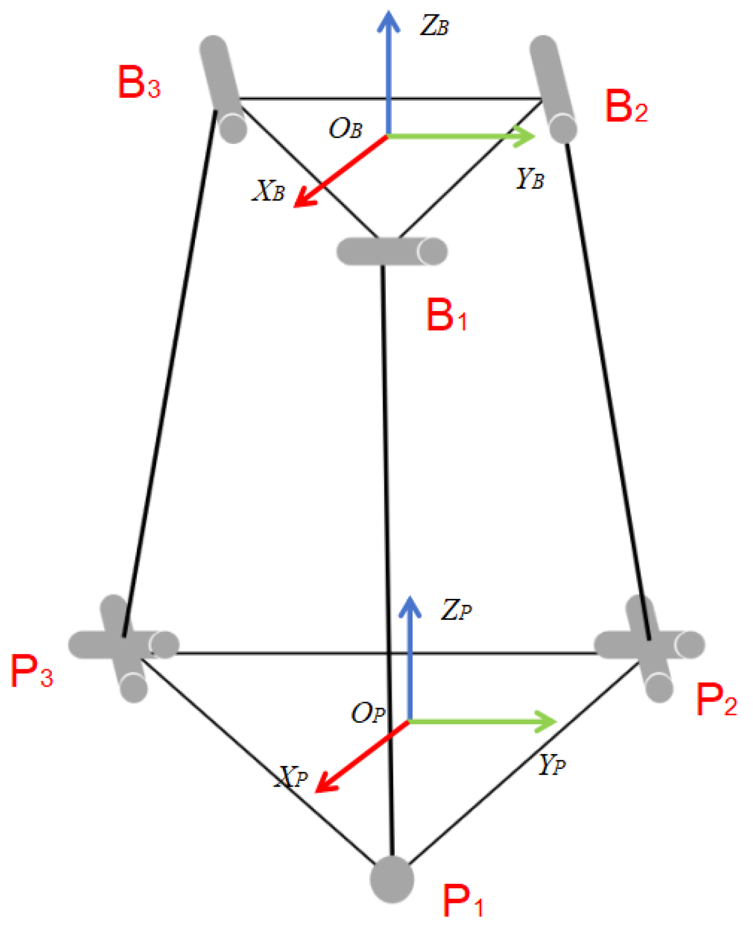
As shown in Figure 4, a fixed coordinate frame () is established at the centre of the fixed platform, and a moving coordinate frame () is attached to the centre of the moving platform. The -axis is aligned with the longitudinal direction of the robot, the -axis is directed laterally, and the -axis is normal to the platform. Limb 1 denotes the front RPS limb, whereas limbs 2 and 3 denote the rear-left and rear-right RPU limbs, respectively.
Figure 4.
Kinematic schematic of the 2RPU–RPS mechanism.
To describe the T-shaped arrangement of the mechanism, the attachment-point coordinates on the fixed platform are defined as
where is the position vector of the -th fixed-platform joint in frame . Similarly, the attachment points on the moving platform are expressed in frame as
Here, and are the longitudinal distances from the platform centres to the front RPS attachment points; and are the longitudinal distances to the two rear RPU attachment points; and and denote the corresponding lateral half-spacings.
With roll defined as rotation about the -axis and pitch as rotation about the -axis, the orientation matrix of the moving platform relative to the fixed platform is taken as
In the kinematic model, and denote the roll and pitch rotations of the moving platform relative to the chassis-mounted fixed platform, respectively.
Because the prescribed task space contains only vertical translation and rotations about the - and -axes, the longitudinal and lateral translations of the moving platform are constrained. Therefore, the translation vector of the moving-platform centre relative to the fixed-platform frame is expressed as
where denotes the vertical position of the moving-platform centre relative to the fixed-platform coordinate frame. According to the rigid-body coordinate transformation, the position of the -th moving-platform joint expressed in frame is
To ensure the reproducibility of the kinematic model and subsequent simulations, the principal geometric parameters of the inverted 2RPU–RPS mechanism are summarized in Table 1. The attachment-point coordinates are defined with respect to the corresponding fixed- and moving-platform coordinate systems established above. The fixed and moving platforms adopt congruent T-shaped attachment layouts. Therefore, the corresponding attachment points have identical in-plane coordinates in their respective platform coordinate systems. All geometric parameters were obtained from the three-dimensional mechanical model and remained unchanged throughout the simulation.
Table 1.
Geometric parameters of the 2RPU–RPS mechanism.
The value applies when the corresponding fixed- and moving-platform attachment points are vertically aligned at the nominal configuration and the reported neutral actuator length represents the complete joint-to-joint limb length.
The vector directed from the fixed-platform joint to the corresponding moving-platform joint is consequently given by
or equivalently,
The theoretical length of the -th actuated limb is obtained from the Euclidean norm of :
Substitution of the T-shaped attachment-point coordinates into Equation (24) yields the explicit inverse-kinematic expressions of the three actuated limbs. For the front RPS limb,
For the rear-left RPU limb,
For the rear-right RPU limb,
Equations (25)–(27) constitute the complete nonlinear inverse-kinematic mapping between the prescribed moving-platform pose and the three actuator lengths by retaining the trigonometric coupling among roll, pitch, and vertical displacement. In the control-oriented simulation, these equations are evaluated using the desired time-varying pose to generate the actuator-length commands, while the corresponding nonlinear geometric constraints are used to reconstruct the actual platform pose, as detailed in Section 5.3.
The rigid-body transformation established above is applicable not only to the moving-platform attachment points but also to any point rigidly connected to the moving platform. Accordingly, the position of the disc–soil contact point is determined in Section 4.3 by introducing its fixed offset vector in frame .
4.2. Singularity and Feasible-Workspace Analysis
The kinematic feasibility of the inverted 2RPU–RPS mechanism depends on both the actuator stroke limits and the distance of the mechanism from singular configurations. Based on the nonlinear inverse-kinematic model established in Section 4.1, the moving-platform pose vector and actuator-length vector are defined as
Differentiating the inverse-kinematic relationship with respect to time gives
where is the reduced Jacobian matrix relating the moving-platform velocity to the actuator-length rates:
For compact formulation, the limb vector and its corresponding unit vector are defined as
The elements of the -th row of the reduced Jacobian can then be expressed as
where
A kinematic singularity occurs when the reduced Jacobian loses rank:
which is equivalently expressed as
At a singular configuration, a finite moving-platform velocity may require an excessively large actuator velocity, or a commanded actuator motion may fail to produce a unique platform motion.
At the nominal configuration,
the fixed and moving platforms have corresponding vertically aligned attachment points. For the congruent T-shaped layouts adopted in this study, the reduced Jacobian becomes
Its determinant is
Because , , and are positive geometric parameters, Equation (39) is nonzero. Therefore, the nominal configuration is not a singular configuration.
Because the three columns of contain quantities with different physical dimensions, a characteristic length is introduced to obtain the dimensionally normalized Jacobian:
In the present analysis, the characteristic length is selected as . At the nominal configuration, the condition number of the normalized Jacobian is approximately
The relatively low condition number indicates that actuator-length variations are transmitted to the three task-space motions without pronounced kinematic amplification near the nominal configuration.
The task-oriented feasible workspace is defined as the set of platform poses that simultaneously satisfy the actuator stroke constraints and the Jacobian-rank condition:
where is a small positive threshold used to exclude configurations close to singularity. The actuator-length limits are determined from the nominal limb length and the available electric-cylinder stroke:
For the mechanism considered in this study,
giving
In the simulated operating conditions, the maximum absolute actuator displacement was , which was substantially smaller than the allowable stroke of . The simulated trajectories therefore remained within the stroke-limited task workspace, with a minimum remaining stroke margin of . Together with the nonsingularity of the nominal configuration, these results indicate that the mechanism operated within a locally feasible kinematic region under the considered attitude- and downforce-regulation conditions.
The workspace defined above is a task-oriented kinematic workspace. Passive-joint angular limits, manufacturing tolerances, joint clearance, and possible structural interference are not independently modelled in the present system-level simulation and will be examined through detailed multibody modelling and prototype verification.
4.3. Disc-Opener Penetration and Downforce Model
The disc opener is mounted away from the centre of the moving platform. Consequently, roll and pitch rotations of the moving platform can change the vertical position of the disc–soil contact point even when the vertical position of the platform centre remains unchanged. To account for this geometric coupling, a ground-fixed coordinate frame is introduced, with the positive -axis directed vertically upward.
A representative soil-entry point is defined on the disc opener. Its position relative to the moving-platform centre is constant in frame and is expressed as
where , , and denote the longitudinal, lateral, and vertical offsets of the representative contact point from the moving-platform centre, respectively.
According to the rigid-body transformation established in Section 4.1, the position of point expressed in the chassis-mounted fixed-platform frame is
where
and
is the nonlinear roll–pitch rotation matrix defined in Equation (19). Here, , , and are the reconstructed vertical position, roll angle, and pitch angle of the moving platform relative to the chassis-mounted fixed platform.
Because frame moves together with the robot chassis, the chassis pose relative to the ground-fixed frame must also be considered. Let
denote the position of the fixed-platform centre in frame . Neglecting chassis yaw in the present model, its orientation matrix is expressed as
where and are the chassis roll and pitch angles, respectively.
The complete position of the disc–soil contact point in the ground-fixed frame is therefore
The vertical coordinate of the contact point is obtained as
Similarly, the horizontal coordinates and are obtained from the first and second components of . The local terrain elevation beneath the transformed contact point is represented by
where denotes the terrain-surface elevation and is its value at the nominal configuration.
Taking the nominal disc-opener penetration as , the instantaneous penetration is calculated from the relative vertical displacement between the local terrain surface and the transformed disc–soil contact point:
where is the vertical coordinate of point in the nominal configuration. The nonnegative constraint ensures that penetration becomes zero when the disc opener loses contact with the soil.
The corresponding penetration velocity is expressed as
Equations (46)–(56) show that disc-opener penetration depends not only on terrain elevation and the vertical translation of the moving platform, but also on the vertical displacement of the offset contact point induced by chassis roll, chassis pitch, and the compensatory roll–pitch motion of the parallel mechanism. Therefore, the attitude- and downforce-regulation loops are geometrically coupled through the transformed contact-point position.
For performance evaluation, the penetration deviation from its nominal reference is defined as
where denotes the nominal penetration corresponding to the prescribed operating condition. The penetration deviation is used as a soil-engagement performance index and is not introduced into a separate penetration-feedback loop.
During soil engagement, the disc opener is subjected to a vertical soil reaction. Considering the unilateral nature of opener–soil contact, the penetration–downforce relationship is represented by an equivalent stiffness–damping model:
where is the vertical soil reaction acting on the disc opener, and and are the actual time-varying soil stiffness and damping coefficients used only in the soil-contact plant model. The unilateral formulation prevents the soil model from producing a nonphysical tensile force when contact is lost.
For a prescribed downforce , the instantaneous downforce error is defined as
The force calculated using Equation (58) represents the unfiltered soil reaction. The downforce signal used in the feedback controller is processed by the low-pass filter introduced in Section 5.2.
Under quasi-static operating conditions, the penetration velocity is relatively small, and the damping contribution can be neglected. Provided that the disc opener remains in contact with the soil, Equation (58) can be approximated as
Accordingly, using a fixed nominal soil stiffness, the penetration reference corresponding to the prescribed downforce can be estimated as
Here, is the actual soil stiffness in the soil-contact model, whereas is the fixed nominal stiffness used by the controller. In this study, was fixed at 11.43 kN/m throughout the varying-soil simulation. Equation (61) provides the fixed stiffness-based penetration reference for the feedforward component, while the PI feedback component subsequently adjusts the vertical command according to the measured downforce error. The corresponding simulation parameters are summarized in Table 2. The penetration calculated in this section represents the geometric penetration of the disc opener into the soil and should not be interpreted as the final buried depth of the seed.
Table 2.
Principal parameters for the simulation.
4.4. Electric-Cylinder Actuator Model
The dynamic response of the electric cylinders directly affects the accuracy and transient behaviour of the moving-platform adjustment. Under normal operating conditions, each actuator is represented by a first-order inertial model with explicit velocity and stroke constraints:
where is the actual absolute length of the -th electric cylinder, is its absolute target length, is the actuator time constant, and is the maximum admissible extension or retraction velocity. In the control implementation, the target actuator length is calculated directly from the desired moving-platform pose using the nonlinear inverse-kinematic model described in Section 5.3.
The actuator stroke is constrained by
where and are the lower and upper stroke limits, respectively. The saturation operator in Equation (62) is defined as
When neither the velocity limit nor the stroke boundary is activated, Equation (62) reduces to the conventional first-order actuator equation,
The resulting model retains the simplicity required for system-level simulation while accounting for actuator response delay, rated velocity, and finite stroke. These constraints were incorporated into the MATLAB/Simulink R2023a odel to provide a more realistic representation of the electric-cylinder-driven adjustment process.
5. Coordinated Feedforward–PI Control Strategy
A coordinated feedforward–PI control strategy was adopted to regulate the roll, pitch, and vertical soil-engagement state of the seeding end effector. The control system consists of two attitude-control loops and one downforce-control loop. The attitude loops combine chassis-disturbance feedforward compensation with end-effector attitude-error feedback, whereas the vertical loop combines a soil-stiffness-based penetration reference with downforce-error feedback.
The outputs of the three control loops are synthesized into the desired moving-platform pose and subsequently converted into the target displacements of the three electric cylinders through the kinematic model of the 2RPU–RPS mechanism.
5.1. Roll and Pitch Control
Let and denote the chassis roll and pitch disturbances, respectively, and let and denote the compensatory rotations generated by the parallel mechanism. The absolute roll and pitch angles of the seeding end effector are
The desired absolute roll and pitch angles are both set to zero. The corresponding attitude errors are therefore
The desired compensatory angles are generated using chassis-attitude feedforward and PI feedback:
The feedforward terms provide direct compensation for the measured chassis disturbances, while the PI terms correct residual errors caused by actuator delay and model simplification. Integral and output limitations are applied to prevent excessive accumulation and commands beyond the allowable operating range.
5.2. Downforce Control
The vertical-control loop regulates the vertical soil reaction acting on the disc opener. The soil-reaction signal calculated using the penetration–downforce model is processed by a first-order low-pass filter before being introduced into the feedback loop:
where is the instantaneous soil reaction calculated using Equation (58), is the filtered downforce used for feedback, and is the force-filter time constant.
The downforce-tracking error is defined as
where is the prescribed downforce.
Based on the equivalent soil stiffness, the nominal penetration required to generate the prescribed downforce is calculated as
where is the fixed nominal soil stiffness used by the controller, and is the maximum allowable penetration command. In all varying-soil simulations, was fixed at 11.43 kN/m and was not updated according to the instantaneous soil properties. The controller was not assumed to know, measure, or estimate the actual time-varying soil stiffness, which was applied only in the soil-contact plant model.
The PI controller generates an additional penetration correction according to the filtered downforce error:
The resulting penetration command is expressed as
The penetration command should be converted into the desired vertical position of the moving platform by considering the complete spatial position of the disc–soil contact point, rather than by using only the vertical displacement of the moving-platform centre. Because the local terrain elevation is not introduced directly into the controller as a feedforward signal, the desired vertical coordinate of the representative contact point in the ground-fixed frame is defined relative to its nominal value as
where is the vertical coordinate of the representative disc–soil contact point at the nominal configuration, and is the nominal opener penetration.
According to the complete rigid-body transformation established in Equation (52), the desired contact-point position satisfies
where
Taking the vertical component of the above transformation and solving for gives
where
and denote the instantaneous position and orientation of the chassis-mounted fixed-platform frame relative to the ground-fixed frame, respectively, and is the fixed offset vector from the moving-platform centre to the representative disc–soil contact point. The denominator in Equation (79) represents the vertical projection of the -axis and remains nonzero within the prescribed operating range.
Equation (79) converts the commanded penetration into the required vertical position of the moving-platform centre while accounting for chassis translation, chassis roll and pitch, the desired compensatory platform attitude, and the geometric offset of the disc–soil contact point. Therefore, the vertical command compensates for the contact-point displacement induced by roll and pitch regulation instead of assuming that the contact point moves identically with the moving-platform centre.
The local terrain elevation is still treated as an external disturbance acting on the opener–soil-engagement process rather than as a directly measured feedforward input. Its influence on the actual penetration is reflected through the downforce-feedback loop. When the filtered downforce is lower than the prescribed value, the positive force error increases , decreases the desired contact-point height , and consequently commands the disc opener to move downward. Conversely, excessive downforce reduces the penetration command and raises the desired contact-point height. The penetration correction and the resulting moving-platform-position command are limited to remain within the feasible operating range.
5.3. Nonlinear Kinematic Mapping and Pose Reconstruction
The outputs of the attitude- and downforce-control loops are combined to form the desired moving-platform pose. The desired roll and pitch angles, and , are generated by the two attitude-control loops, whereas the desired vertical position is obtained from the commanded disc–soil contact-point height using the complete transformation in Equation (79). Therefore, the desired vertical position is not determined using a moving-platform-centre-only approximation, but accounts for the instantaneous chassis pose, the desired platform attitude, and the fixed contact-point offset.
To maintain consistency with the complete inverse-kinematic formulation established in Section 4.1, the desired pose is converted into actuator-length commands using the nonlinear geometric model without introducing a locally linearized mapping. The desired moving-platform pose vector is defined as
where , , and denote the desired vertical position, roll angle, and pitch angle of the moving platform relative to the chassis-mounted fixed platform, respectively.
The corresponding desired translation vector is
According to the nonlinear inverse-kinematic relationship derived in Section 4.1, the desired length of the -th actuated limb is calculated as
where and are the attachment-point position vectors on the fixed and moving platforms, respectively, and is the nonlinear roll–pitch rotation matrix defined in Equation (19).
The desired actuator-length vector and the corresponding displacement command relative to the nominal configuration are expressed as
and
where is the nominal limb-length vector.
The absolute target-length vector is introduced into the constrained electric-cylinder dynamics established in Equations (62)–(64), in which actuator response delay, velocity limitation, and stroke constraints are considered.
After the actuator dynamics are applied, the actual limb lengths are used to reconstruct the moving-platform pose through the nonlinear forward-kinematic constraint equations:
where
The reconstructed actual moving-platform pose is written as
The nonlinear constraint equations in Equation (86) are solved numerically at each sampling instant. The pose obtained at the previous sampling instant is used as the initial value of the iterative solver to improve convergence and preserve the continuity of the reconstructed motion.
The reconstructed moving-platform pose is not introduced into the soil-contact model through alone. Instead, the reconstructed translation vector
and rotation matrix
Using the reconstructed platform pose, the actual position of the disc–soil-contact point is evaluated from the complete coordinate transformation established in Equation (52). The local terrain elevation, opener penetration, and vertical soil reaction are subsequently calculated using Equations (54), (55), and (58), respectively. The soil-reaction signal is processed by the low-pass filter in Equation (71) and returned to the downforce-control loop, while the reconstructed relative attitude is combined with the chassis attitude according to Equations (66) and (67) to obtain the absolute roll and pitch feedback. Thus, the nonlinear inverse kinematics, constrained actuator dynamics, forward-kinematic reconstruction, and disc–soil-contact model form a unified closed-loop calculation chain.
6. Simulation Model and Operating Conditions
6.1. Model Architecture
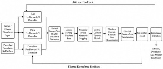
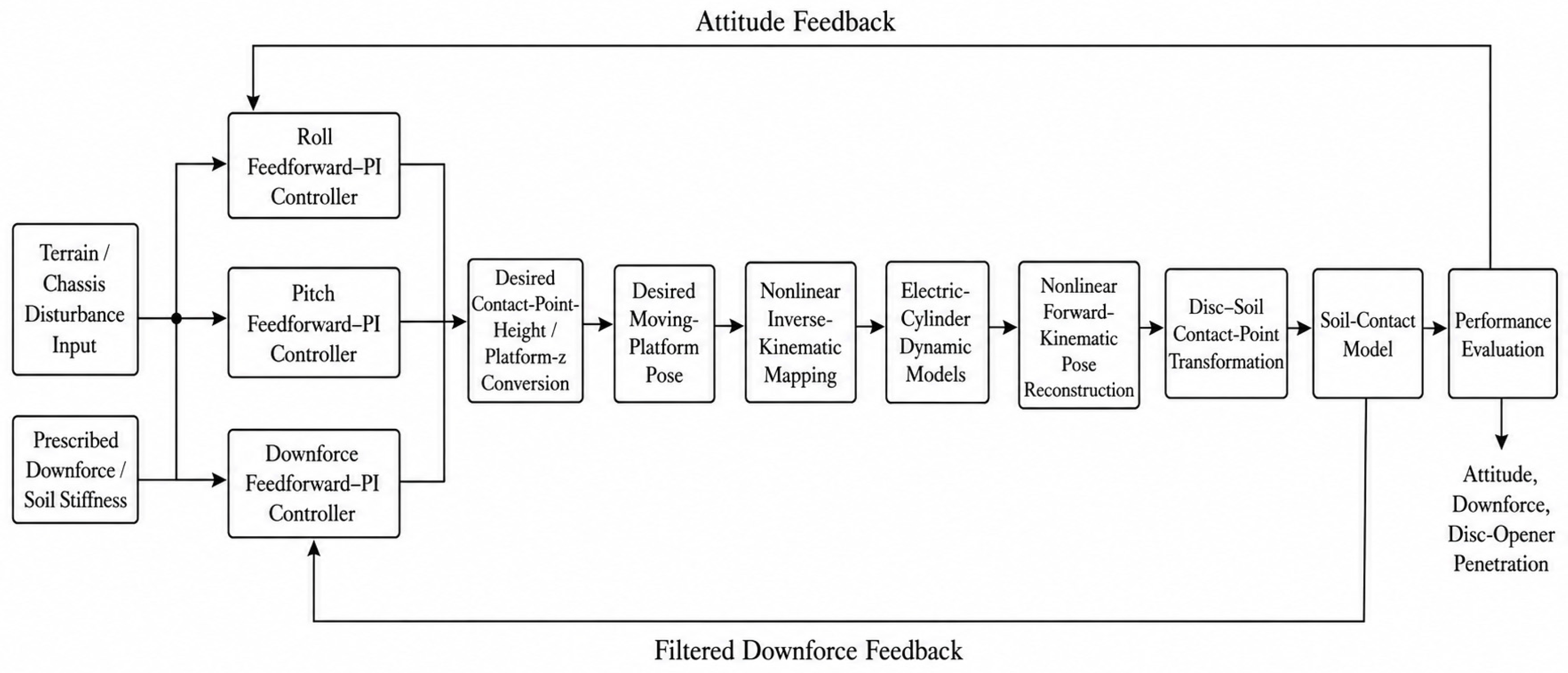
A MATLAB/Simulink model was developed to evaluate the attitude- and downforce-regulation performance of the inverted 2RPU–RPS end-effector system. As illustrated in Figure 5, the model comprises a terrain- and chassis-disturbance input module, three coordinated feedforward–PI control loops, a nonlinear inverse-kinematic mapping module, three constrained electric-cylinder dynamic modules, a nonlinear forward-kinematic reconstruction module, a complete disc–soil contact-point transformation module, a unilateral soil-contact module, and performance-evaluation modules.
Figure 5.
Closed-loop architecture of the coordinated feedforward–PI control system.
The control loops generate the desired vertical position, roll angle, and pitch angle of the moving platform. The desired pose is converted into actuator-length commands through the nonlinear inverse-kinematic model, while the actuator dynamics and forward-kinematic reconstruction determine the actual platform pose. The reconstructed pose is subsequently introduced into the contact-point and soil-engagement models established in Section 4.3 and Section 5.3 to obtain the end-effector attitude, opener penetration, and downforce feedback. These feedback signals close the corresponding attitude- and downforce-control loops, as shown in Figure 5.
A fixed-step discrete solver was adopted with a sampling interval of 0.01 s. The forward operating speed of the robot was set to 1.5 m/s. The prescribed downforce was 400 N. Three simulation conditions were established to evaluate attitude compensation, vertical downforce regulation, and coordinated three-degree-of-freedom control during multiple-row operation.
The feedforward–PI controller gains were selected through response-based trial-and-error tuning rather than analytical tuning or numerical optimization. The parameters were adjusted according to the transient response and steady-state tracking accuracy observed in the closed-loop simulations of the roll, pitch, and downforce-control loops. The final gain set reported in Table 2 was selected to provide a balanced closed-loop tracking response under the nominal operating conditions.
To ensure the reproducibility of the simulation model, the principal parameters used in the simulations are summarized in Table 2.
6.2. Simulation Scenarios
Three simulation scenarios were constructed to provide a comprehensive assessment of mechanism performance. The external disturbances were generated deterministically in MATLAB and imported into Simulink as time-series signals through From Workspace blocks. In the vertical-control scenario, the terrain-elevation input was synthesized using multi-frequency undulations and localized bump/depression events. In the attitude-control scenario, staged roll and pitch signals were prescribed to evaluate independent and coupled attitude compensation. In the multi-row scenario, the chassis roll and pitch angles were reconstructed from terrain-height differences between virtual left–right and front–rear wheel contact points along a two-dimensional field surface. Therefore, the disturbance inputs were predefined operating-condition signals rather than random noise.
The first scenario considered roll and pitch control. Its purpose was to evaluate the ability of the mechanism to compensate for end-effector roll and pitch under chassis-attitude disturbances. The simulation lasted 40 s, corresponding to an equivalent travel distance of 60 m. Roll disturbances were imposed predominantly during 0–10 s, pitch disturbances during 10–20 s, and combined roll–pitch disturbances during 20–40 s. The reference values of both end-effector attitude angles were set to .
The second scenario examined vertical downforce regulation and disc-opener penetration response. It was designed to evaluate active regulation of disc-opener penetration and downforce. The simulation duration was 40 s, the travel distance was 60 m, and the prescribed downforce was 400 N. The vertical position of the moving platform was adjusted according to variations in terrain elevation and downforce error, with the objective of maintaining a disc-opener penetration depth of approximately 35 mm.
The third operating condition was designed to evaluate the coordinated control performance of the mechanism during continuous multi-row field operation. The simulated field comprised seven straight seeding rows, each 54.0 m long, giving a total effective operating distance of 378.0 m. At a forward speed of 1.5 m/s, the corresponding straight-row operating time was 252 s. Six headland-transition intervals of 8 s each were introduced between adjacent rows, resulting in a total simulation duration of 300 s. The modelled field dimensions were 54.0 m × 5.2 m, and the peak-to-valley terrain variation was approximately 100 mm. Under this operating condition, roll, pitch, and vertical downforce were regulated simultaneously, while disc-opener penetration was evaluated as an additional soil-engagement performance variable.
6.3. Evaluation Metrics
Root mean square error, mean absolute error, maximum absolute error, mean penetration depth, and maximum actuator displacement were selected to quantify the performance of the attitude-adjustment mechanism.
The root mean square error of an attitude angle is calculated as
where is the actual value at the -th sampling instant, is the reference value, and is the number of samples. When represents roll or pitch, Equation (91) gives the corresponding roll or pitch RMSE.
The mean absolute downforce error is defined as
where is the target downforce and is the actual downforce at the -th sampling instant. This metric represents the average deviation of the controlled downforce from its reference value.
7. Simulation Results and Discussion
7.1. Roll and Pitch Regulation Performance
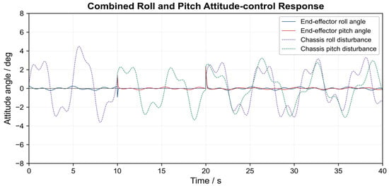
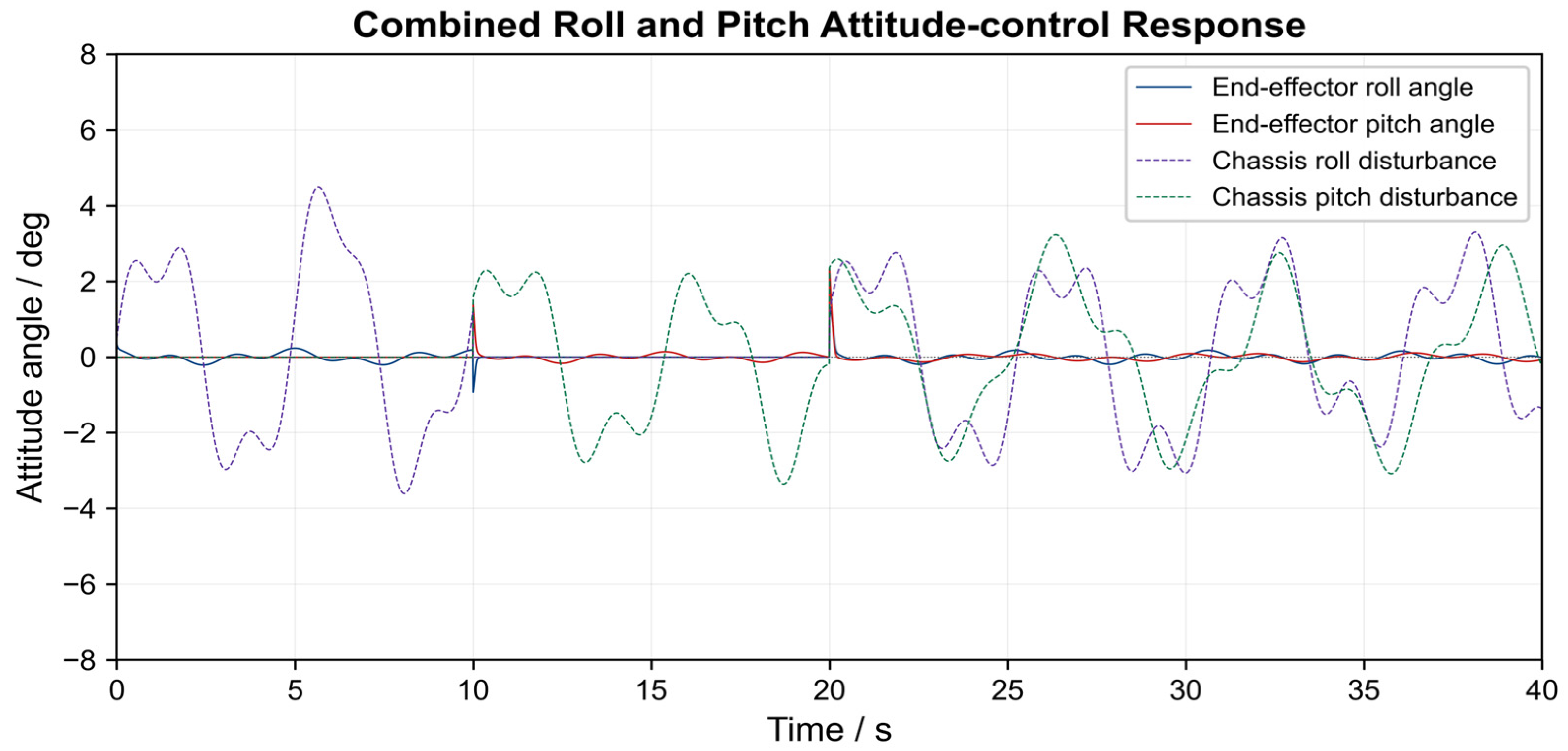
As shown in Figure 6, the maximum chassis roll and pitch disturbances were approximately and , respectively. After active regulation of the moving platform by the electric cylinders, the roll RMSE of the end effector was , with a maximum absolute error of . The corresponding pitch RMSE was , and the maximum absolute pitch error was . The transient attitude errors were reduced to a relatively small range within a short period, indicating that the mechanism can effectively attenuate the transmission of chassis disturbances to the seeding end effector.
Figure 6.
Control responses of the roll and pitch angles.
The relatively large differences between the maximum absolute errors and the corresponding RMSE values in both the roll and pitch channels are mainly attributed to the short transient peaks occurring at the transition instants of the prescribed chassis-attitude disturbances. When the roll or pitch disturbance changes abruptly, the first-order electric-cylinder dynamics and actuator-velocity constraints prevent the mechanism from instantaneously generating the required compensating motion. Consequently, relatively large attitude errors occur briefly during these transitions, particularly near the abrupt pitch-disturbance change at approximately 20 s. After each transition, both the roll and pitch errors decrease rapidly and remain close to zero for most of the simulation period. Therefore, the maximum absolute errors characterize isolated transient responses, whereas the RMSE values of 0.109° for roll and 0.114° for pitch represent the generally small tracking errors over the complete 40 s simulation.
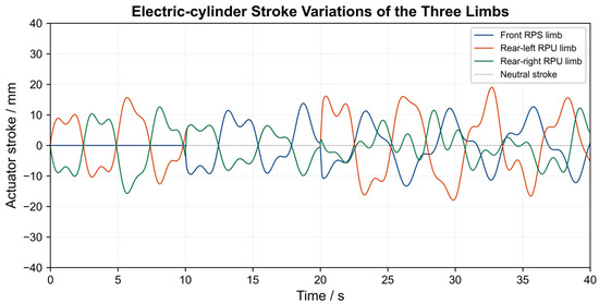
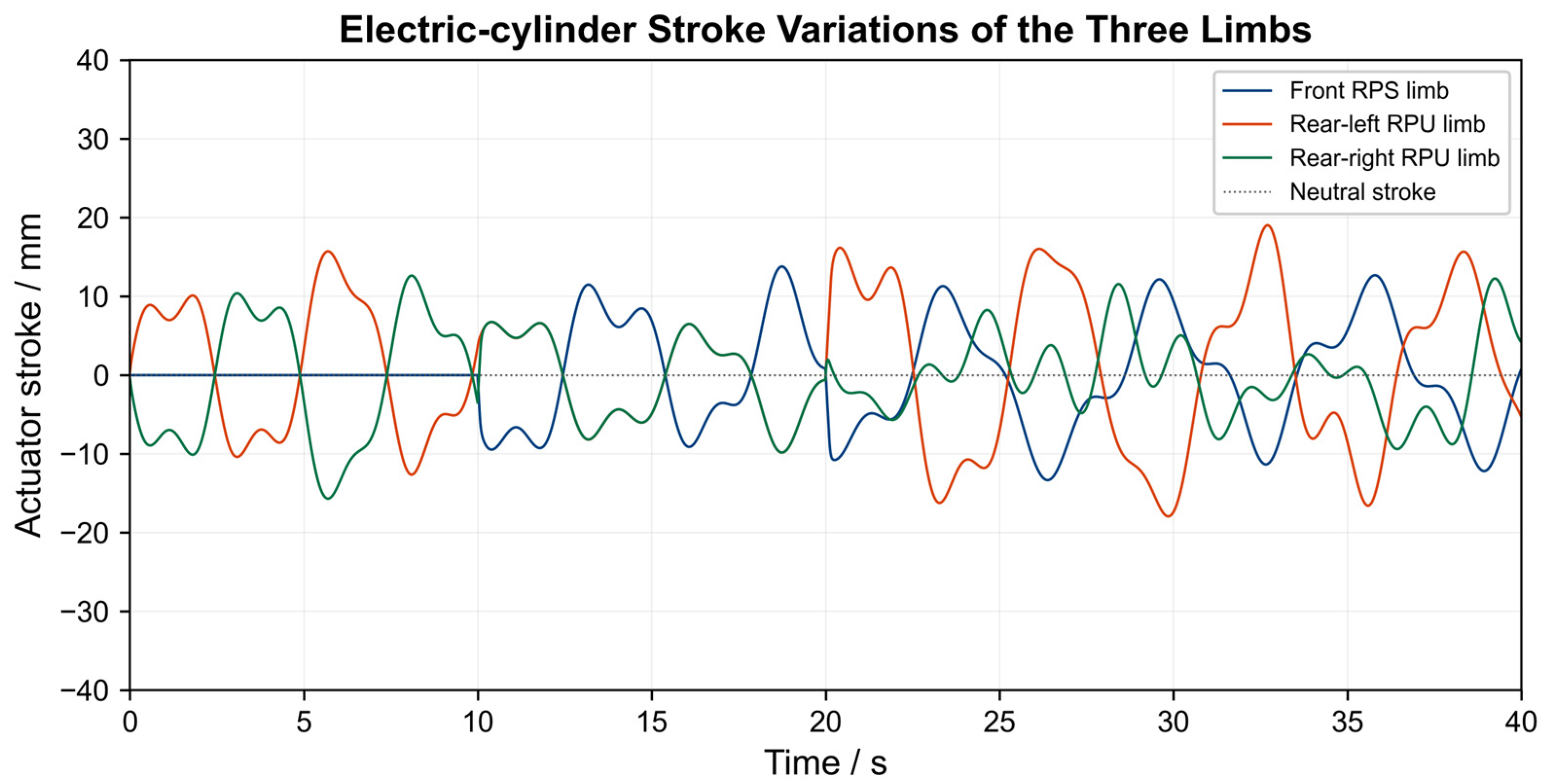
Figure 7 presents the electric-cylinder displacement responses. The maximum absolute displacement was 13.80 mm for the front RPS limb, 19.05 mm for the left RPU limb, and 15.71 mm for the right RPU limb. All three displacement demands remained moderate. The required actuator stroke is therefore compatible with a compact prototype configuration.
Figure 7.
Variation curves of electric-cylinder extension in the three limbs.
The results confirm that differential displacement between the two RPU limbs generates effective roll compensation, whereas differential displacement between the front RPS limb and the rear limbs produces pitch compensation. For a maize seeding robot, this regulation reduces the influence of chassis inclination on both the soil-entry attitude of the disc opener and the orientation of the terminal seed tube.
7.2. Vertical Downforce Regulation and Disc-Opener Penetration Response
The vertical-control simulation was performed to evaluate active regulation of disc-opener penetration and downforce. The prescribed downforce was 400 N, and the corresponding theoretical penetration depth was approximately 35 mm. Terrain elevation varied from −44.77 to 19.55 mm. In response to the terrain profile and the measured downforce error, the controller adjusted the vertical position of the moving platform.
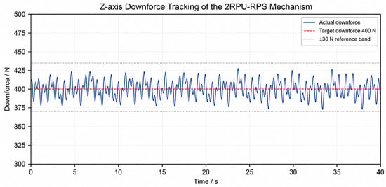
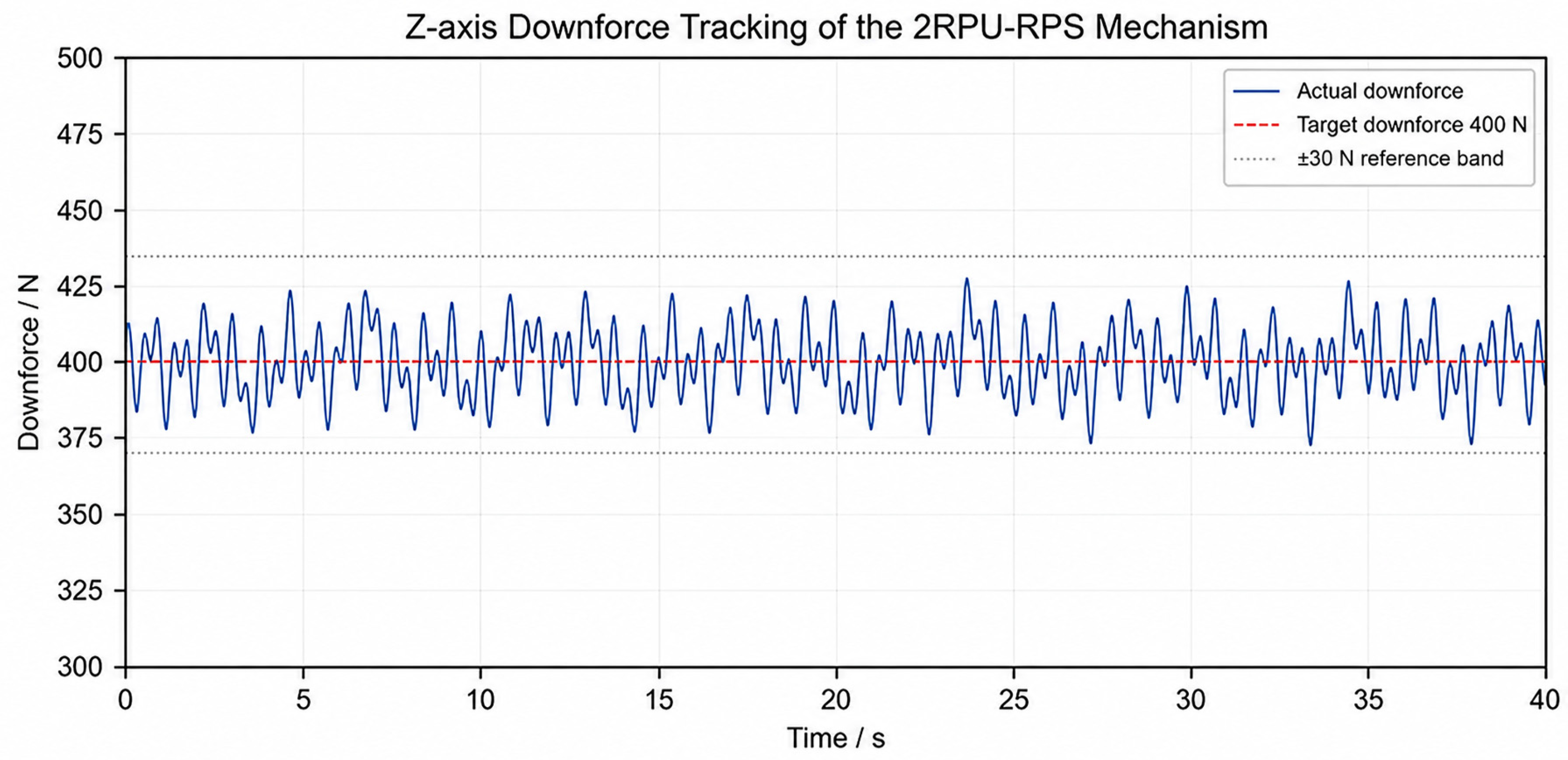
As shown in Figure 8, electric-cylinder control maintained the actual downforce between 372.59 and 427.17 N. The mean absolute downforce error was 9.09 N, the downforce RMSE was 11.07 N, the 95th-percentile absolute error was 20.87 N, and the maximum absolute error was 27.41 N.
Figure 8.
Z-direction downforce tracking of the 2RPU–RPS mechanism.
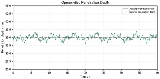
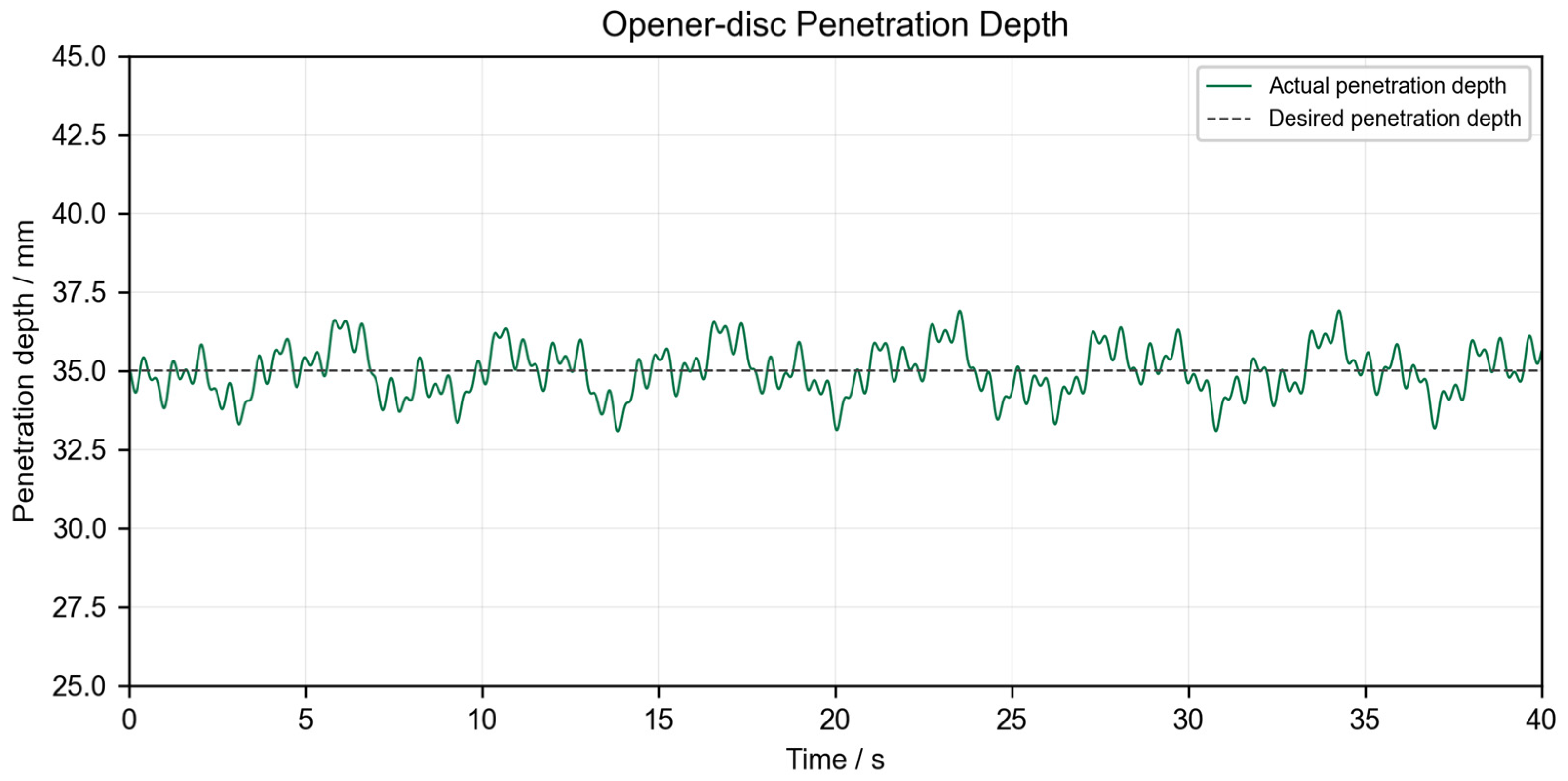
Figure 9 shows the variation in disc-opener penetration depth. With a target value of 35 mm, the mean disc-opener penetration was 34.99 mm, with a variation range of 33.08–36.91 mm. Active electric-cylinder regulation therefore maintained the opener close to the prescribed penetration and improved the consistency of disc-opener penetration and soil engagement.
Figure 9.
Variation in the penetration depth of the disc opener.
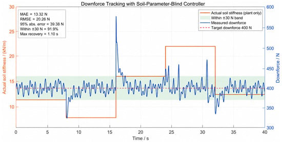
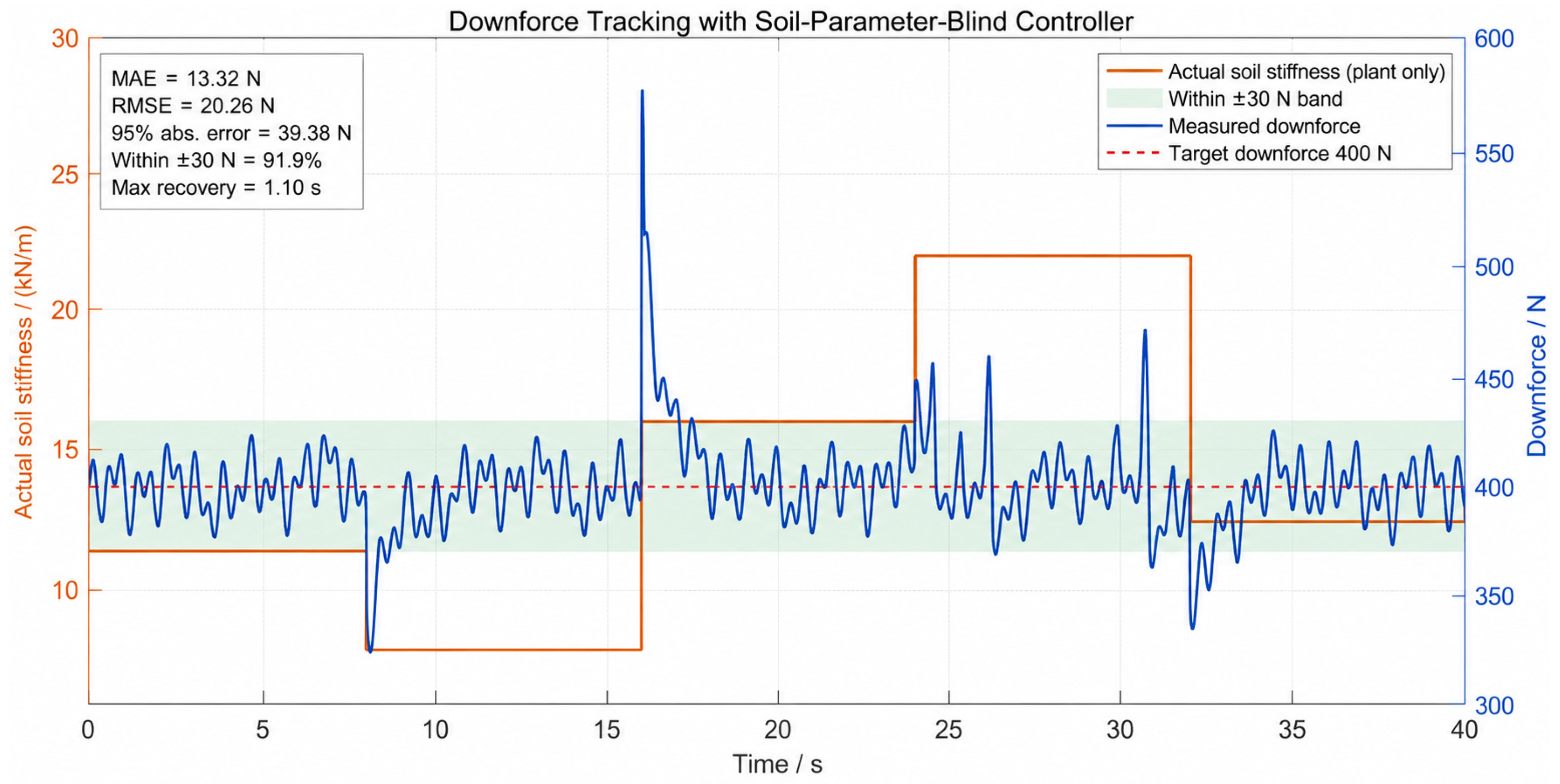
To further characterize the response of the vertical regulation system under spatially varying soil conditions, several representative soil regions were introduced sequentially during the simulation. The corresponding soil-contact parameters and penetration characteristics are summarized in Table 3, while the target downforce was maintained at 400 N throughout the test. These successive time intervals represent different spatial soil regions encountered by the robot along its travel path rather than temporal variations in the soil properties at a fixed location.
Table 3.
Controller and plant parameters under soil-parameter-mismatch conditions.
In this parameter-mismatch test, the controller used the same fixed nominal stiffness throughout the simulation, whereas the actual soil stiffness and damping varied sequentially in the plant model according to Table 3.
As shown in Figure 10, the proposed controller maintained stable downforce regulation despite the mismatch between the fixed nominal stiffness used in the controller and the spatially varying stiffness and damping applied in the soil-contact plant model. Over the complete simulation, the mean absolute error and root mean square error were 13.32 N and 20.26 N, respectively, and 91.93% of the samples remained within ±30 N of the 400 N reference. The largest deviations occurred only during abrupt transitions between adjacent soil regions. After excluding the 1 s transient period following each parameter change, the mean absolute error decreased to 10.20 N, the root mean square error decreased to 13.19 N, and 97.74% of the downforce samples remained within ±30 N of the reference. These results indicate that the downforce-feedback loop can effectively compensate for variations in the actual soil properties without requiring instantaneous soil-stiffness information, while maintaining relatively stable soil engagement under the considered parameter-mismatch conditions.
Figure 10.
Downforce-tracking response under piecewise-varying soil-stiffness conditions.
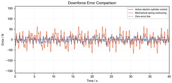
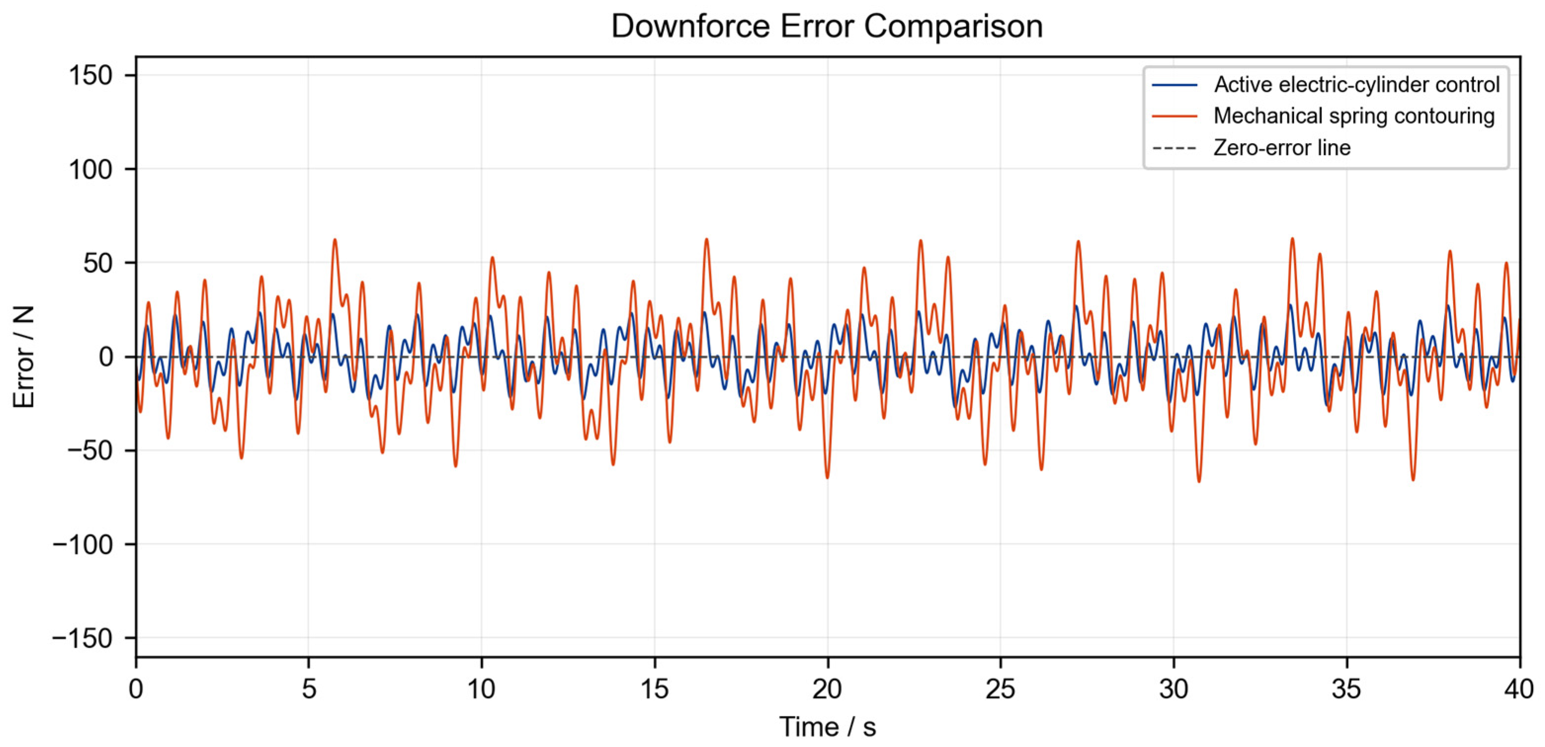
To provide a quantitative baseline comparison of vertical soil-engagement performance, the proposed active electric-cylinder system was evaluated against a conventional mechanically spring-loaded ground-following system. Because the passive spring-loaded four-bar mechanism provides only vertical ground-following motion and cannot actively regulate roll or pitch, the comparison was restricted to the common downforce-regulation function.
As shown in Figure 11, the mean absolute downforce error was 20.54 N for the passive spring baseline and 9.09 N for the proposed active system, corresponding to a reduction of approximately 55.7%. The passive system accommodates terrain variations through spring deformation and linkage motion, and its downforce response is therefore affected by spring stiffness and structural response delay. In contrast, the proposed system actively adjusts the end-effector position according to the downforce-feedback signal, resulting in more stable soil engagement under the simulated operating condition.
Figure 11.
Downforce comparison: active control vs. spring profiling.
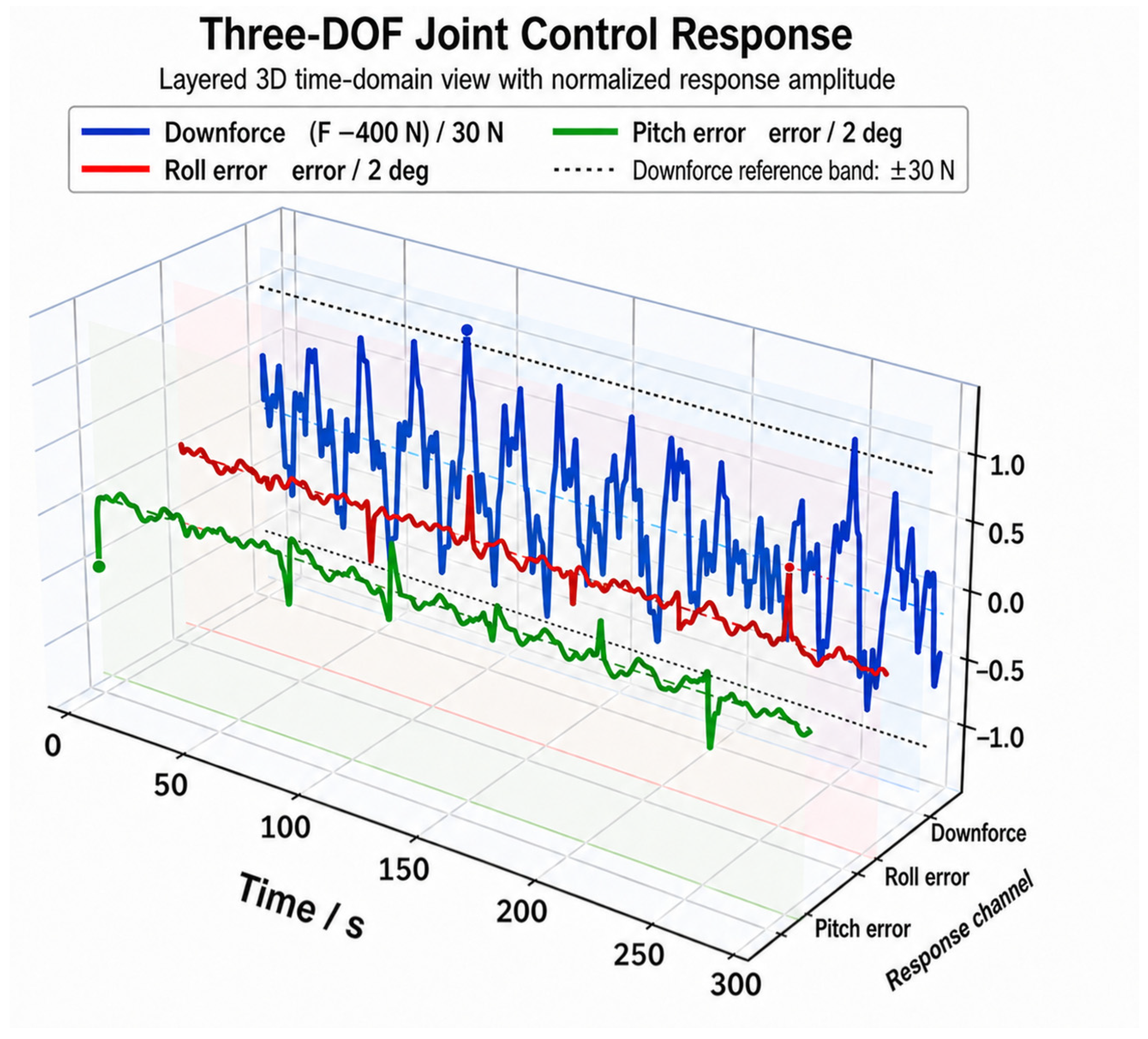
7.3. Coordinated Three-Degree-of-Freedom Control During Multi-Row Field Operation
A multi-row field simulation was conducted to assess the integrated attitude-regulation capability of the mechanism during continuous operation.
As shown in Figure 12, the actual downforce ranged from 365.91 to 439.05 N, with an RMSE of 12.65 N. The mean penetration depth was 34.96 mm and varied from 31.65 to 38.14 mm. Because the terrain profile in this scenario was more complex than that used for isolated vertical control, the control error increased slightly; nevertheless, the overall response remained stable.
Figure 12.
Three-degree-of-freedom coordinated control response.
The maximum chassis roll and pitch disturbances were approximately and , respectively. Following compensation, the end-effector roll RMSE was , and the pitch RMSE was . These results indicate that the 2RPU–RPS mechanism can suppress the transmission of chassis-attitude disturbances during continuous multi-row seeding and maintain relatively stable attitudes of both the disc opener and the seed tube.
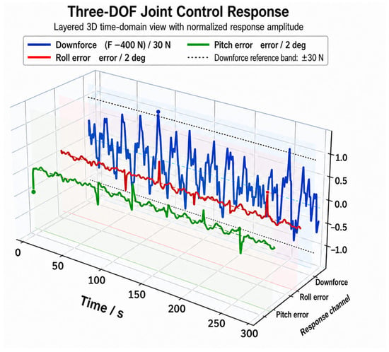
To display variables with different physical units in a common three-dimensional coordinate system, the downforce deviation, roll error, and pitch error were normalized by 30 N, 2°, and 2°, respectively. This normalization was used only for visualization, whereas all quantitative performance indices were calculated from the original physical signals.
To examine whether the coordinated control performance depended on a narrowly selected parameter set, a brief gain-sensitivity analysis was conducted under the multi-row operating condition. All proportional and integral gains were simultaneously scaled to 80% and 120% of their baseline values, while the terrain input, chassis disturbances, soil parameters, actuator constraints, initial conditions, and solver settings remained unchanged. The roll RMSE, pitch RMSE and downforce RMSE were selected as the evaluation indices.
As summarized in Table 4, the coordinated controller remained stable when all PI gains were varied by . The principal tracking-error indices changed only moderately, and no sustained oscillation or actuator stroke saturation was observed. Although the baseline gains provided the most balanced overall response, the results indicate that the reported control performance was not restricted to one narrowly selected parameter set.
Table 4.
Sensitivity of the coordinated multi-row control performance to PI-gain scaling.
In Figure 13, the lower surface and its contour lines represent the original field terrain and describe the surface undulations encountered along the seeding paths. The strip-shaped surfaces above the terrain represent the regulated end-platform attitude and illustrate the combined roll and pitch responses during continuous multi-row operation. The colour map denotes the downforce error.
Figure 13.
Three-degree-of-freedom coordinated control for multi-row seeding on undulating terrain.
Under a peak-to-valley terrain variation of approximately 100 mm, seven seeding rows, a row spacing of 0.70 m, and an operating speed of 1.5 m/s, the platform maintained a continuous attitude response as the terrain changed. The downforce RMSE was 12.65 N. The proposed coordinated control strategy therefore achieved a satisfactory compromise between attitude stabilization and downforce tracking over undulating terrain.
8. Conclusions
An inverted 2RPU–RPS parallel end effector was developed to reduce the effects of terrain-induced chassis disturbances on the attitude and soil engagement of a compact maize seeding robot. The mechanism provides one vertical translational and two rotational degrees of freedom for coordinated regulation of the disc opener and terminal seed tube. A nonlinear kinematic model, a unilateral penetration–downforce model, constrained electric-cylinder dynamics, and a coordinated feedforward–PI control strategy were established in MATLAB/Simulink.
The main contribution of the proposed design and control strategy is to extend conventional vertical depth/downforce regulation to coordinated regulation of soil engagement and seeding-end attitude. By assigning the vertical degree of freedom to penetration/downforce regulation and the two rotational degrees of freedom to roll and pitch compensation, the 1T2R mechanism enables simultaneous adjustment of the disc opener and terminal seed tube under chassis disturbances. The coordinated control framework further combines chassis-attitude feedforward compensation with end-effector attitude and downforce feedback, allowing the system to respond to both chassis disturbances and variations in local soil properties.
Under isolated chassis-attitude disturbances, the end-effector roll and pitch RMSEs were and , respectively. The maximum actuator displacement was 19.05 mm and remained within the prescribed stroke range. Under the nominal soil condition and a prescribed downforce of 400 N, the downforce RMSE was 11.07 N, while the mean disc-opener penetration remained close to the nominal value at 34.99 mm. These results indicate that the proposed system can attenuate chassis-attitude disturbances while maintaining relatively stable soil engagement under the adopted model assumptions.
During the 300 s multi-row simulation, the downforce RMSE was 12.65 N and the mean disc-opener penetration was 34.96 mm. After active compensation, the roll and pitch RMSEs were and , respectively. The controller also remained stable when all PI gains were varied simultaneously by , indicating that the coordinated response was not restricted to a narrowly selected gain set.
The present study is limited to system-level MATLAB/Simulink simulation. Joint clearance, structural deformation, actuator force and power requirements, sensor noise, nonlinear three-dimensional soil interaction, and detailed steering dynamics were not considered. Future work will include ADAMS–Simulink co-simulation, prototype development, soil-bin testing, and field experiments to evaluate the actual operating performance of the proposed mechanism.
Author Contributions
Conceptualization, Z.W. , S.Y. and Q.W.; methodology, Z.W. and S.Y.; validation, Z.W., Y.Z. and T.L.; formal analysis, Z.W. and Y.Z.; investigation, Z.W. and Y.Z.; resources, S.Y. and Q.W.; data curation, Z.W.; writing—original draft preparation, Z.W.; writing—review and editing, Y.Z., T.L., S.Y. and Q.W. All authors have read and agreed to the published version of the manuscript.
Funding
This research received no external funding.
Data Availability Statement
The data presented in this study are available on request from the corresponding author.
Conflicts of Interest
The authors declare no conflicts of interest.
Abbreviations
The following symbols and abbreviations are used in this manuscript:
| PLC | Programmable Logic Controller |
| RPU | Revolute–Prismatic–Universal |
| RPS | Revolute–Prismatic–Spherical |
| 2RPU–RPS | Parallel mechanism composed of two RPU limbs and one RPS limb |
| 1T2R | One translational and two rotational degrees of freedom |
| PI | Proportional–Integral |
| RMSE | Root-mean-square error |
| MAE | Mean absolute error |
References
- Yang, L.; Yan, B.X.; Zhang, D.X.; Zhang, T.L.; Wang, Y.X.; Cui, T. Research Progress on Precision Planting Technology of Maize. Trans. Chin. Soc. Agric. Mach. 2016, 47, 38–41. (In Chinese) [Google Scholar] [CrossRef]
- Yang, L.; Yan, B.X.; Yu, Y.M.; He, X.T.; Liu, Q.W.; Liang, Z.J.; Yin, X.W.; Cui, T.; Zhang, D.X. Global Overview of Research Progress and Development of Precision Maize Planters. Int. J. Agric. Biol. Eng. 2016, 9, 9–26. [Google Scholar] [CrossRef]
- Raoufat, M.H.; Mahmoodieh, R.A. Stand Establishment Responses of Maize to Seedbed Residue, Seed Drill Coulters and Primary Tillage Systems. Biosyst. Eng. 2005, 90, 261–269. [Google Scholar] [CrossRef] [Scilit]
- Zhai, C.; Long, J.; Taylor, R.; Weckler, P.; Wang, N. Field Scale Row Unit Vibration Affecting Planting Quality. Precis. Agric. 2020, 21, 589–602. [Google Scholar] [CrossRef] [Scilit]
- Virk, S.S.; Fulton, J.P.; Porter, W.M.; Pate, G.L. Row-Crop Planter Performance to Support Variable-Rate Seeding of Maize. Precis. Agric. 2020, 21, 603–619. [Google Scholar] [CrossRef] [Scilit]
- Li, H.; He, J.; Wang, C.; Yang, W.; Lin, H.; Wang, Q.; Yang, H.; Tan, L. Research Progress on the Development of the Planter Unit for Furrowing Control and the Depth Measurement Technology. Appl. Sci. 2023, 13, 11884. [Google Scholar] [CrossRef] [Scilit]
- Shang, J.; Liu, D.; Song, X.; Han, Y.; He, S.; Zhang, Y.; Liu, L.; Chen, H. Sowing Depth Stability Analysis and Test Verification of No-Tillage Planter Parallel 4-Bar Row Unit. Heliyon 2024, 10, e36721. [Google Scholar] [CrossRef] [Scilit] [PubMed]
- Yang, L.; Zhang, R.; Gao, N.; Cui, T.; Liu, Q.W.; Zhang, D.X. Performance of No-Till Corn Precision Planter Equipped with Row Cleaners. Int. J. Agric. Biol. Eng. 2015, 8, 15–25. [Google Scholar] [CrossRef]
- Yang, J.; Wu, H.; Guo, A.; Rugerinyange, R.; Liu, C.; Zhao, Z.; Han, W.; Yin, L. Performance Optimization and Simulation Test of No-Tillage Corn Precision Planter Based on Discrete Element Method. Machines 2024, 12, 465. [Google Scholar] [CrossRef] [Scilit]
- Sharda, A.; Fulton, J.; Badua, S.; Griffin, T.W.; Ciampitti, I.; Haag, L. Planter Downforce Technology for Uniform Seeding Depth; MF3331; Kansas State University Research and Extension: Manhattan, KS, USA, 2017. [Google Scholar]
- Bai, H.J.; Fang, X.F.; Wang, D.C.; Yuan, Y.W.; Zhou, L.M.; Niu, K. Design and Experimental Evaluation of an Integrated Control System for Seeding Depth and Soil Compaction of a Maize Planter. Trans. Chin. Soc. Agric. Mach. 2020, 51, 61–72. (In Chinese) [Google Scholar] [CrossRef]
- Zhao, J.H.; Liu, L.J.; Yang, X.J.; Liu, Z.J.; Tang, J.X. Design and Laboratory Test of Control System for Depth of Furrow Opening. Trans. Chin. Soc. Agric. Eng. 2015, 31, 35–41. [Google Scholar]
- Nielsen, S.K.; Nørremark, M.; Green, O. Sensor and Control for Consistent Seed Drill Coulter Depth. Comput. Electron. Agric. 2016, 127, 690–698. [Google Scholar] [CrossRef] [Scilit]
- Jing, H.; Zhang, D.; Wang, Y.; Yang, L.; Fan, C.; Zhao, H.; Wu, H.; Zhang, Y.; Pei, J.; Cui, T. Development and Performance Evaluation of an Electro-Hydraulic Downforce Control System for Planter Row Unit. Comput. Electron. Agric. 2020, 172, 105073. [Google Scholar] [CrossRef] [Scilit]
- Badua, S.A.; Sharda, A.; Strasser, R.; Ciampitti, I.; Griffin, T.W. Influence of Planter Downforce Setting and Ground Speed on Seeding Depth and Plant Spacing Uniformity of Corn. In Proceedings of the 14th International Conference on Precision Agriculture, Montreal, QC, Canada, 24–27 June 2018; pp. 1–13. [Google Scholar]
- Badua, S.A.; Sharda, A.; Strasser, R.; Ciampitti, I. Ground Speed and Planter Downforce Influence on Corn Seed Spacing and Depth. Precis. Agric. 2021, 22, 1154–1170. [Google Scholar] [CrossRef] [Scilit]
- Strasser, R.; Badua, S.A.; Sharda, A.; Rothmund, M. Development of a Test Stand to Quantify the Response of a Planter’s Automatic Downforce Control System. Trans. ASABE 2021, 64, 1533–1543. [Google Scholar] [CrossRef] [Scilit]
- Liu, L.; Wang, X.; Zhang, X.; Cheng, X.; Wei, Z.; Ji, J.; Li, H.; Zhang, H.; Wang, M. Sowing Depth Control Strategy Based on the Downforce Measurement and Control System of ‘T’-Shaped Furrow Opener. Biosyst. Eng. 2024, 247, 97–108. [Google Scholar] [CrossRef] [Scilit]
- Chen, F.; Yang, L.; Cui, T.; Zhang, D.; He, X.; Zhang, K.; Jiang, Y.; Zhang, X.; Wang, X.; Mou, J. Design and Experiment of Sowing Depth Control System Based on Forward Direction Surface Slope. Comput. Electron. Agric. 2026, 243, 111376. [Google Scholar] [CrossRef] [Scilit]
- Azmi, H.N.; Hajjaj, S.S.H.; Gsangaya, K.R.; Sultan, M.T.H.; Mail, M.F.; Hua, L.S. Design and Fabrication of an Agricultural Robot for Crop Seeding. Mater. Today Proc. 2023, 81, 283–289. [Google Scholar] [CrossRef] [Scilit]
- López-Gómez, J.A.; Patiño-Espejel, J.E.; Velázquez-López, N.; Sánchez-Chávez, D.I.; Van Loon, J. Design and Comparison of Two Maize Seeders Coupled with an Agricultural Robot. Machines 2024, 12, 935. [Google Scholar] [CrossRef] [Scilit]
- Vidoni, R.; Bietresato, M.; Gasparetto, A.; Mazzetto, F. Evaluation and Stability Comparison of Different Vehicle Configurations for Robotic Agricultural Operations on Side-Slopes. Biosyst. Eng. 2015, 129, 197–211. [Google Scholar] [CrossRef] [Scilit]
- Jia, X.L.; Shi, Z.; Li, R.; Zhang, G.H.; Geng, D.Y.; Lan, Y.B.; Wang, B.L. Design and Test of Automatic Leveling System for Chassis of Small Agricultural Machinery in Hilly and Mountainous Areas. Trans. Chin. Soc. Agric. Mach. 2024, 55, 108–115. (In Chinese) [Google Scholar] [CrossRef]
- Li, Q.; Hervé, J.M. 1T2R Parallel Mechanisms without Parasitic Motion. IEEE Trans. Robot. 2010, 26, 401–410. [Google Scholar] [CrossRef] [Scilit]
- Ju, Y.; Xu, W.; Meng, G.; Cao, Y. Constraint Characteristics and Type Synthesis of Two Families of 1T2R Parallel Mechanisms. Robotica 2022, 40, 3033–3056. [Google Scholar] [CrossRef] [Scilit]
- Peng, S.; Du, L.; Che, L.; Jin, Z. Dimensional Multi-Objective Optimization Design for 2RPU–RPS Parallel Mechanism. Robotica 2025, 43, 1087–1109. [Google Scholar] [CrossRef] [Scilit]
- Peng, S.; Cheng, Z.; Che, L.; Zheng, Y.; Cao, S. Kinematic Performance Analysis of a Parallel Mechanism for Loading Test of Hydraulic Support. Mech. Mach. Theory 2022, 168, 104592. [Google Scholar] [CrossRef] [Scilit]
- Chen, M.; Zhang, Q.; Qin, X.; Sun, Y. Kinematic, Dynamic, and Performance Analysis of a New 3-DOF Over-Constrained Parallel Mechanism without Parasitic Motion. Mech. Mach. Theory 2021, 162, 104365. [Google Scholar] [CrossRef] [Scilit]
- Cazalilla, J.; Vallés, M.; Valera, Á.; Mata, V.; Díaz-Rodríguez, M. Hybrid Force/Position Control for a 3-DOF 1T2R Parallel Robot: Implementation, Simulations and Experiments. Mech. Based Des. Struct. Mach. 2016, 44, 16–31. [Google Scholar] [CrossRef] [Scilit]
- Xu, Y.; Zhao, X.; Li, G.; Tang, X. Design and Analysis of a 3-UPU Wave Compensation Platform Based on Improved Sliding Mode Control. Ships Offshore Struct. 2024, 19, 2040–2049. [Google Scholar] [CrossRef] [Scilit]
- Chong, Z.; Xie, F.; Liu, X.-J.; Wang, J.; Niu, H. Design of the Parallel Mechanism for a Hybrid Mobile Robot in Wind Turbine Blades Polishing. Robot. Comput.-Integr. Manuf. 2020, 61, 101857. [Google Scholar] [CrossRef] [Scilit]

Disclaimer/Publisher’s Note: The statements, opinions and data contained in all publications are solely those of the individual author(s) and contributor(s) and not of MDPI and/or the editor(s). MDPI and/or the editor(s) disclaim responsibility for any injury to people or property resulting from any ideas, methods, instructions or products referred to in the content. |
© 2026 by the authors. Licensee MDPI, Basel, Switzerland. This article is an open access article distributed under the terms and conditions of the Creative Commons Attribution (CC BY) license.