


Abstract
In aircraft assembly, riveting is a critical joining method that directly determines structural integrity, fatigue life, and overall airframe reliability. With the increasing adoption of human–machine collaborative systems for complex assembly tasks, the rational design of riveting process parameters has become essential for ensuring consistent assembly quality. However, traditional experimental parameter optimization is time-consuming and costly, and lacks generalizability across varying working conditions. To address this challenge, this paper proposes a simulation-based design method for rapidly constructing process parameter schemes in human–machine collaborative aircraft assembly riveting. A theoretical dynamic model of the pneumatic reciprocating riveting gun is established to derive the relationship between input air pressure and piston impact velocity, providing physically grounded loading conditions for numerical simulation. A sequentially coupled numerical simulation method is developed using Ansys LS-DYNA and its Restart function to accurately model the entire multiple reciprocating impact forming process, which incorporating preloading analysis to reflect actual clamping conditions and reset analysis with applied damping to eliminate post-impact oscillations. Taking the riveting assembly of Aluminum (AL) 2024T351 rivets and AL 7039 aluminum sheets as a case study, the simulation successfully reproduces the rivet forming evolution over twelve consecutive impacts, revealing a two-stage deformation mechanism consisting of elastic springback and superimposed elastic-plastic deformation. Experimental verification on a self-built human–machine collaborative riveting platform demonstrates excellent agreement with simulation results in impact counts and upset head height. The proposed method provides a reliable, efficient, and low-cost approach for assembly process parameter calibration, offering direct theoretical support for assembly quality control, process robustness, and reliability assurance in aircraft manufacturing.
1. Introduction
In aircraft assembly, riveting remains one of the major joining methods, directly determining the assembly accuracy, structural integrity, and overall reliability of the final aircraft. The quality of riveted connections is therefore a cornerstone of assembly quality assurance, that any inconsistency in rivet forming can precipitate premature failure and drastically compromise the service life of the assembly. With the increasing adoption of human–machine (robot) collaborative systems for complex assembly tasks, the rational design of riveting process parameters has become an essential task in assembly oriented manufacturing. Due to high variety and complexity, aircraft components are mainly assembled manually [1,2], However, manual riveting operations are tedious, repetitious, costly, prone to error, difficult to guarantee quality, and also causing health and ergonomic problems [3]. Therefore, the forms of automatic riveting or human–machine collaborative riveting have been proposed. Human–machine collaboration in assembly combines human flexibility with machine precision control, emerging as a new form of aircraft riveting assembly. This approach not only frees up a worker but also addresses operations in confined, enclosed, or other inaccessible spaces that automated drilling and riveting equipment cannot reach.
From a macro perspective, the development of human–machine collaborative riveting assembly requires addressing issues such as task allocation and execution between human–machine collaborative riveting assemblies, identification of human–machine collaborative intentions, path planning for human–machine collaboration, and security settings for human–machine collaborative assembly systems [4]. The content of this article belongs to the research on task allocation and execution process between human–machine collaboration, mainly studying the design of process parameter schemes in the riveting process of human–machine collaboration assembly aircraft. During the aircraft riveting assembly process, due to complex structures, multiple functional areas, and various types of aircraft types, the riveting conditions vary (mainly reflected in the operating objects: rivet specifications, connected part specifications, riveting forms, forming process requirements, etc.). The process parameters of manual collaborative riveting mainly rely on the operational experience of workers, with strong experience and significant individual differences; for human–machine collaborative riveting, the key to implementing human–machine collaborative riveting is the design of riveting process parameters for different riveting conditions.
The most direct way to obtain riveting process parameters is to design experiments that extract the technical parameters from the manual collaborative riveting operation process, which can efficiently respond to the parameter scheme design of a specific working condition. When facing the demand for riveting assembly with multiple aircraft types and working conditions, it is impractical to implement a large number of experiments from the perspective of cost and efficiency. Therefore, researching new methods to break through different aircraft riveting assembly conditions and obtain efficient and low-cost riveting process parameters for human–machine collaborative assembly will become a key factor in promoting the promotion of human–machine collaborative riveting technology.
To address these challenges, this paper proposes a simulation-based design method for process parameter schemes in human–machine collaborative aircraft assembly riveting. The method enables rapid construction of riveting process parameters across diverse working conditions, thereby supporting assembly quality control, process robustness, and the efficient deployment of human–machine collaborative riveting technology in aircraft manufacturing.
Against the above practical challenges in aircraft riveting assembly, numerous scholars have conducted extensive investigations to resolve related technical bottlenecks. To clarify the development vein, research progress, existing disputes and limitations within this field, this section systematically reviews representative domestic and international studies published in recent years.
Li Yuwen et al. set up the robot riveting experimental system, modeled the percussive impact rivet gun, and analyzed the nonlinear equation of elastic-plastic deformation of rivets [1]. Xi fengfeng et al. proposed a complete sequencial of robot riveting process control, including robot, driving gun, and bucking bar [5]. Li Yuwen et al. studied the optimal process parameters to ensure the alignment of the riveting gun during the riveting process [6], and Guo Shuai et al. analyzed the robot vibration caused by impact during the riveting process and the impact of vibration on riveting, exploring the most suitable working area for robot riveting, which is the area with minimal vibration, and guiding the planning of appropriate trajectories during riveting operations [7]. Robot automatic riveting is mainly used for riveting assembly operations in complex working conditions, complex structures. The riveting tool selection required a compact and lightweight pneumatic riveting gun for the system with great flexibility, low cost, high efficiency, and compact structure [8]. Human–machine collaboration riveting has the same requirements for riveting tools.
The robot automatic riveting system usually consists of robot A, robot B and a gantry. The riveting gun is held by robot A, aluminum plates are clamped by gantry, and the bucking bar is held by robot B. Compared to traditional automated drilling and riveting equipment, the robot operation end has higher flexibility. However, corresponding to narrow operating spaces and semi enclosed operating spaces, such as the riveting assembly of the intake duct, the solution of configuring two sets of robots is still very challenging. So the human–machine collaborative riveting with the cooperation of humans and machines has emerged.
For the execution of human–machine collaborative riveting operations, key parameters such as the rivet type, riveting air pressure, impact time, and bucking force must be determined based on the specific working conditions. Precision percussive riveting requires a number of key research issues to be identified, such as riveting forming mechanisms, riveting time determination, riveting air pressure, riveting vibration, riveting tool design, and rivet insertion control [5]. The identification of these issues can be studied through combining experimental and numerical simulations with theory.
In terms of experimental research, Jonathan Y. Ahn et al. studied riveting process parameters from the perspective of ergonomics and designed an experimental platform to evaluate the relationship between percussive riveting operation time, riveting force, riveting tool mass, impact index, and work efficiency [8]. Thomas W. Mcdowell measured the vibration of riveting tools from both experimental and field environments, including acceleration of tool handle and vibration spectrum [9]. Sheng Lih Peng measured and analyzed the vibration characteristics of pneumatic riveting from an ergonomics perspective, and proposed suggestions for improving riveting tools [10]. Rahul Kadam analyzed the vibration characteristics and digital model of a pneumatic impact hammer, which is similar to a pneumatic riveter [10]. The motion of the reciprocating, pneumatic impact tool, as well as the air-driven piston inside the tool, was modeled with a MATLAB computer code by William Allan Bloxsom [11].
In terms of numerical simulation, a large number of finite element analysis methods have been applied to analyze the riveting process. Deng Jianghua et al. established a numerical simulation analysis model for electromagnetic riveting deformation by Ansys [12]. K. Iyer established a riveting model to analyze the influence of interference and clamping on fretting fatigue in single rivet-row lap joints [13], Elzbieta Szymczyk applied a local–global approach in modeling, established a rivet model with a compensator, analyzed the stress distribution of riveting holes, considered Coulomb friction of connectors, and applied the elastic-plastic material model [14]. V. Blanchot et al. established three finite element models (FEMs) to study the numerical characteristics of riveting processes from different perspectives [15]. Zhang Kaifu used ABAQUS to establish the riveting process model and simulated the deformation of an aircraft’s thin walled sheet metal parts, but the multiple reciprocating riveting impact processes were not presented in the literature [16]. Wang Hailong performed numerical simulations of the impact process in direct riveting using ABAQUS software and employed the restart method to simulate the multiple-impact forming process [17]. However, the bucking bar, as a critical tool in practical riveting operations, was not explicitly modeled and was replaced by an equivalent preload force. In actual production, the bucking bar significantly influences the quality of the riveted joint. Its contact condition at the rivet tail directly affects the propagation path and attenuation characteristics of the impact stress wave within the rivet, thereby exerting a decisive influence on the final upset head geometry and internal stress distribution.
A lot of numerical simulation analysis has been conducted on the riveting process, but the above analysis rarely involves accurate analysis of the multiple reciprocating riveting impact processes, and most of them tend to simplify or omit key components involved in the riveting process, such as the piston, hammer, and bucking bar, and rarely include all of them in the finite element model. This practice deviates considerably from real engineering conditions. The complete incorporation of all the above-mentioned components into the modeling and analysis framework is therefore a fundamental starting point and a key novelty of the present study, which is firmly grounded in actual process conditions.
This article proposes a sequential coupled numerical simulation analysis method for the design of riveting parameters in the human–machine collaborative aircraft riveting process parameter scheme. It analyzes the piston speed and the riveting pressure, establishes a finite element model incorporating the piston, rivet hammer, rivet, bucking bar and aluminum sheets, imposes preload and other boundary conditions, that the entire simulation model accurately reflects the actual production riveting conditions and fully captures the complete forming process. This study demonstrates that the full-process simulation analysis of multiple-impact forming, combined with the flexibility to adjust various riveting parameters, enables the accurate determination of process parameters for human–machine collaborative riveting under diverse production scenarios.
2. Human–Machine Collaborative Riveting Experimental Platform
2.1. Scheme of Human–Machine Riveting Experimental Platform
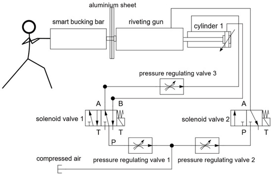
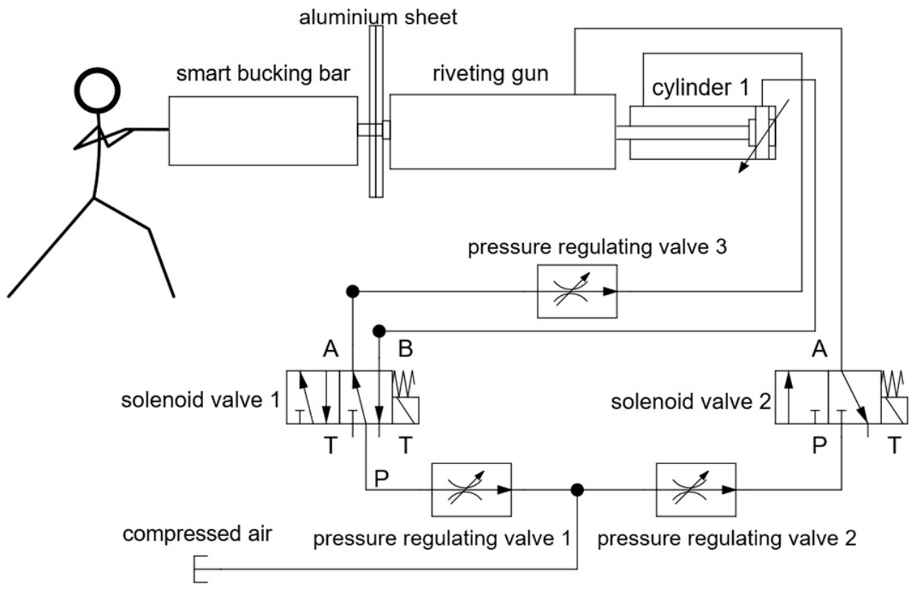
There are two forms of human–machine collaborative riveting assembly: forward riveting and reverse riveting. In this paper, a human–machine collaborative riveting experimental platform is designed for reverse riveting form. The schematic diagram is shown in Figure 1 [18]. During the riveting process, the technician hold the bucking bar to press the tail of the rivet rod, and the riveting gun is supported by the workbench and clamped by the fixture. The Z-direction of the riveting gun is pressed by pneumatic control. The human–machine collaborative riveting process parameters include: air pressure of riveting gun, riveting time, press force, and forming requirements. Compressed air drives the piston to accelerate and strike the riveting hammer, whereupon the kinetic energy is instantly transferred to the rivet, generating an instantaneous impact force—this is the riveting force. This force causes local plastic deformation of the rivet, while the piston rebounds and reverses direction, creating repeated impacts that ultimately form the rivet upset head. The control button of the riveting gun essentially governs the valve of the entire pneumatic circuit. The duration for which the button is pressed determines the number of reciprocating cycles of the piston driven by compressed air. However, in practice, due to factors such as valve response delay, nonlinear characteristics of gas flow, and inertial coupling of reciprocating components, it is difficult to achieve precise control over each individual impact solely by adjusting the pressing duration. The reciprocating pneumatic system is inherently a strongly nonlinear, multi-parameter coupled dynamic system, whose impact process is influenced by multiple factors including air pressure, flow rate, valve characteristics, piston friction, and load variations [19]. The simplified test system constructed in this paper is intended to replicate real production scenarios; however, it does not explicitly model the dynamic characteristics or control accuracy of the pneumatic system itself. Consequently, under the same nominal pressing duration, the actual number of impacts may exhibit some variability (a certain degree of error).
Figure 1.
Block diagram of human–robot collaborative riveting experimental platform.
2.2. Digital Modeling of Riveting Process
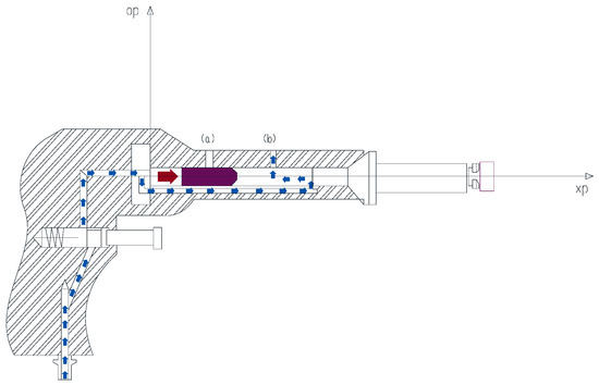
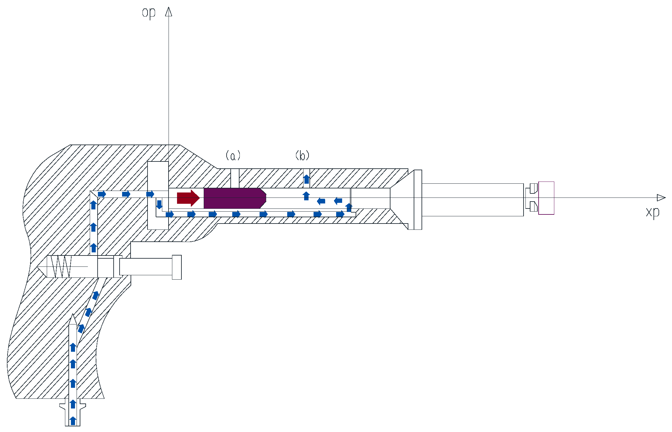
The pneumatic riveting system is a collision system composed of a riveting gun system, rivets, aluminum sheets, and bucking bar [17]. When the riveting gun is working, compressed gas enters the left and right sides of the piston in the riveting gun barrel as seen in Figure 2. When the piston is at the left end, the gas on the right side is discharged into the atmosphere through port , forming a pressure difference between the left and right ends. The piston moves to the right end and collides with the riveting hammer at a speed of , and then the impact acts on the rivet and causes its deformation.
Figure 2.
The pneumatic riveting system.
After the piston hits the riveting hammer, the port is blocked, the gas on the left side is discharged into the atmosphere through port , forming a pressure difference. The piston moves to the left under the function of impact rebound and pressure difference. In this reciprocating process, the rivet undergoes multiple riveting and forming, and forming a rivet upset head finally. The pneumatic riveting model is shown in Figure 2.
The coordinate system shown in Figure 2 is established to describe the piston motion, and the equation of motion is:
where is the mass of piston, is the displacement of the piston, is the cross-sectional area of piston, and is the velocity of piston. represents the pressure acting on the piston, is used to determine the direction of friction, is the friction coefficient between the piston and the barrel, and is the Gravitational acceleration.
When the piston reaches the maximum stroke , the piston impacts the rivet hammer. The collision between the piston and the hammer is assumed as an elastic collision, so as to analyze the transfer process of the impact action. According to the Conservation law of momentum and kinetic energy, the speed of the piston and rivet hammer after impact can be obtained as follows:
where is the velocity of hammer after the impact, is the mass of hammer, is the velocity of the piston before it strikes the riveting hammer, and is the velocity of the piston after the impact.
The impact energy acts on the rivet through the rivet hammer. Since the rivet and the rivet hammer keep in contact during the riveting process, assuming that all the energy is converted into Strain energy, regardless of the kinetic energy, we have:
where represent the impact energy, cross-sectional area, length, axial stress, and strain of the rivet respectively. The strain situation of the rivet can be obtained.
Equation (4) is derived under the constant-volume assumption, which allows the product to be moved outside the integral. However, this simplification requires caution: the axial strain ε = ΔL/L inherently involves length change, and during plastic flow S varies inversely with L. Moreover, the contact area Sr is not constant but depends on the instantaneous hammer travel Lr. Therefore, an accurate energy calculation would require the full stress–strain curve, the final upset length Lr, and the evolution of Sr(Lr). In the absence of such detailed data, Equation (4) serves only as a first-order engineering estimate, useful for trend analysis but not for precise quantitative prediction.
Based on the theoretical analysis, the input air pressure of the riveting gun is ultimately converted into a velocity to implement collisions, while the riveting time controls the number of reciprocating collisions.
3. Sequential Coupled Simulation Method for Multiple-Impact Riveting
When facing the human–machine collaborative riveting work of complex riveting objects, experimental methods consume a lot of manpower, materials, time and other costs. It is necessary to use numerical simulation methods to improve efficiency and reduce costs. A sequential coupling simulation method is proposed for numerical simulation of the riveting process. With the software of Ansys 2022 R1, developer: Ansys, Inc., educational license (Beihang University), its LS-DYNA and LS-DYNA Restart functions could be used for joint simulation, that achieving sequential coupling and simplifying the operating steps. Li Ji et al. applied direct coupling analysis when analyzing the temperature, pre-tightening and impact multi-field coupling of sensors [20].
After studying the direct coupling and sequential coupling method, it is an effective solution for analyzing complex system simulations. The results of the previous analysis as the preprocessing input conditions for the next analysis in the sequential coupling analysis method.
Here is a simulation example to introduce this method.
3.1. Sequential Coupled Simulation Method
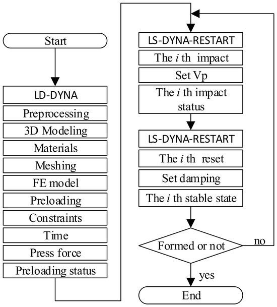
The sequential coupled simulation analysis method mainly consists of model preprocessing, preloading analysis, multiple-impact analysis, and model reset analysis after each impact analysis. Model preprocessing is operated in LS-DYNA module, with main tasks including 3D modeling, adding material attributes, and meshing; preloading analysis is operated in LS-DYNA, including constraint addition, analysis time setting, press force addition, etc.; impact analysis is conducted in LS-DYNA-RESTART, which achieves impact loading by setting the speed of the piston inside the riveting gun; the reset analysis is analyzed in LS-DYNA-RESTART, which stabilizes the system oscillation after impact by setting system damping. The simulation process is shown in the following Figure 3.
Figure 3.
The flowchart of sequential coupled simulation method.
3.2. Preprocessing
3.2.1. 3D Model
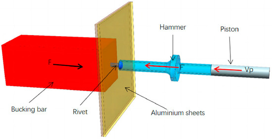
This article establishes a riveting system model based on the characteristics of the reverse riveting process, as shown in Figure 4.
Figure 4.
Riveting schematic model (Bucking bar: the impact stress is acted on the rivet rod, causing the aluminum sheets to be riveted and the rivet to be formed; the bucking bar material is structural steel, set as a rigid body in the simulation model. Rivet: a connector connecting aluminum sheets, set as a flexible component, which undergoes elastic and plastic deformation under the action of impact. Aluminum sheets: connected by rivets, set as flexible parts. Piston: a component of riveting gun. It is the source of impact load, and it obtains a certain velocity under the action of compressed gas, and the kinetic energy generated by this velocity acts as impact energy on the hammer; its material is structural steel, set as a rigid body. Riveting hammer: a component of the riveting gun; the impact force of the piston in the riveting gun directly acts on the rivet. Its material is structural steel and is set as a rigid body).
The above components constitute the entire reverse riveting system. Under the successive action of multiple-impact stress waves, the rivet undergoes progressive plastic deformation and eventually forms an upset head. To simulate this process using the finite element method, it is essential to establish appropriate geometric models, accurate constraint conditions, and well-defined loading boundaries. The material properties and contact interface characteristics significantly influence the propagation and attenuation of impact stress waves and therefore must be carefully taken into account. In the actual process, the piston, rivet hammer, rivet, and bucking bar form a series-connected force transmission and impact chain, while the aluminum sheets serve as the key boundary components constraining the deformation of the rivet, playing a critical role in determining the final upset head geometry and deformation path. All the above-mentioned components must be fully incorporated into the finite element model to faithfully capture the stress wave transmission throughout the system and to reveal the underlying forming mechanism of the rivet. The developed finite element model can be regarded as a digital twin of the pneumatic percussive riveting process, capturing the essential physical behaviors with reasonable fidelity.
In manual riveting, there are two technicians hold the riveting gun and bucking bar respectively. In robot automatic riveting system, the bucking bar and riveting gun are held by robots. In the simulation model, a pair of forces are applied on the bucking bar and riveting hammer to simulate the technicians and robots. The force F’ pressing the riveting gun is acted on the step of the hammer in the model, and the force F pressing the bucking bar is acted on the end face. And set F less than or equal to F’ to ensure that the force acting on the bucking bar does not push the rivet out of the rivet hole.
3.2.2. Geometry
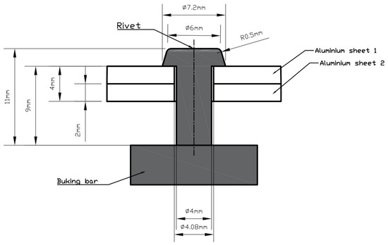
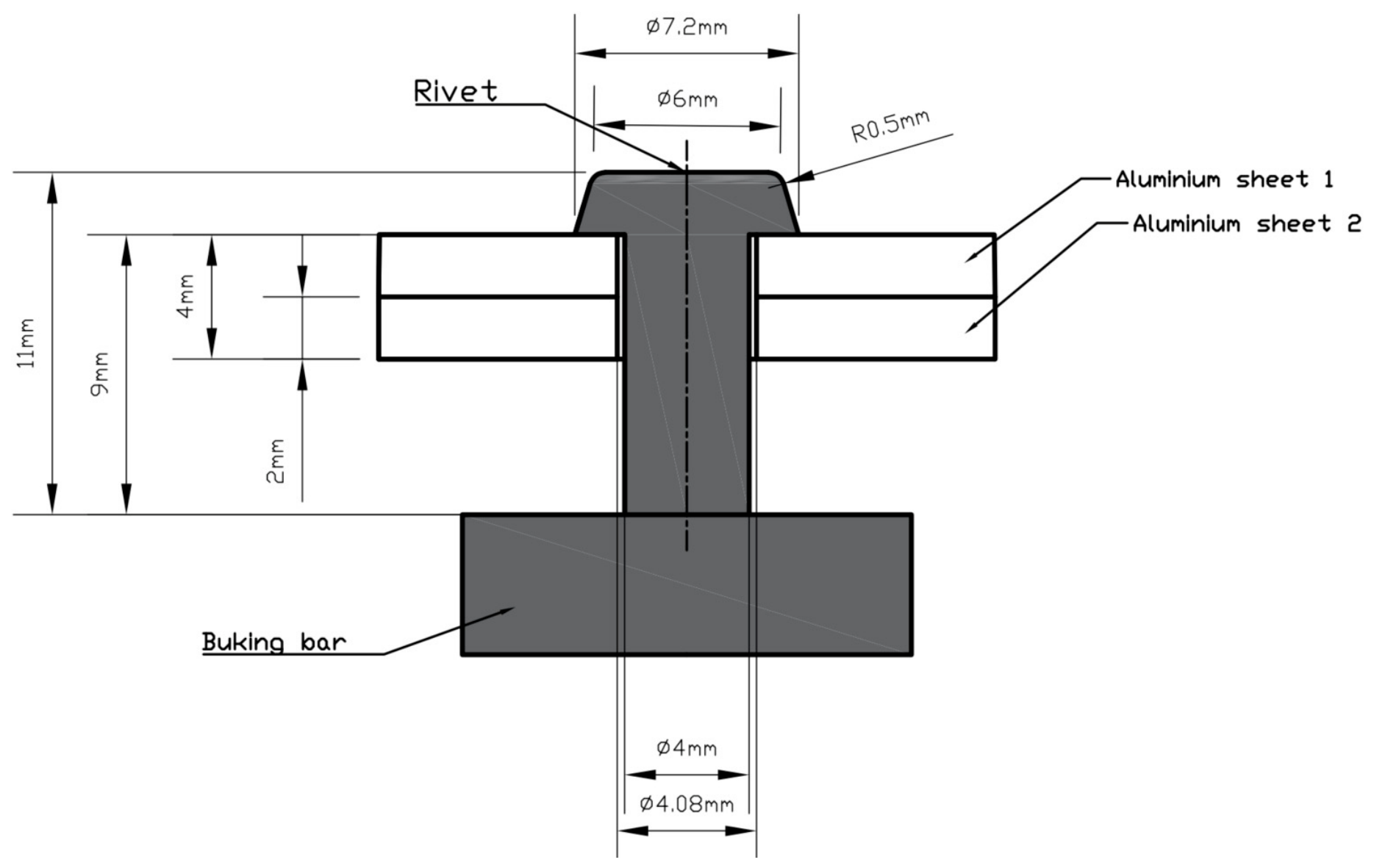
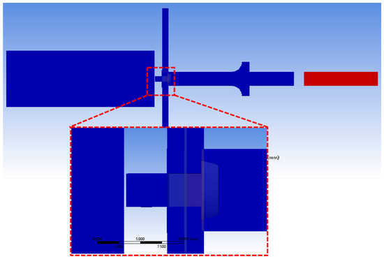
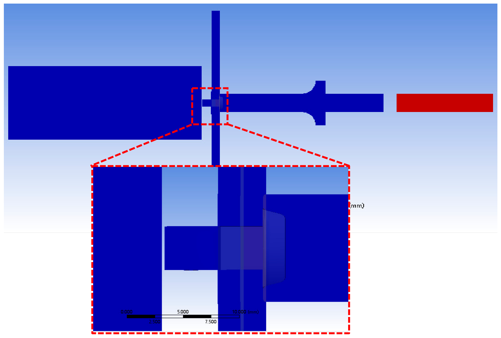
The geometry of key components demonstrated in Figure 5.
Figure 5.
The geometry of key components.
3.2.3. Materials
In this research, the riveting model is built with a rivet, two aluminum alloy sheets, a bucking bar and a hammer. The mechanics parameters are shown in Table 1; we set the bucking bar and hammer as rigid bodies, so the value of yield strength, hardening strength and hardening index are not required.
Table 1.
Mechanics parameters of riveting items.
3.2.4. Meshing
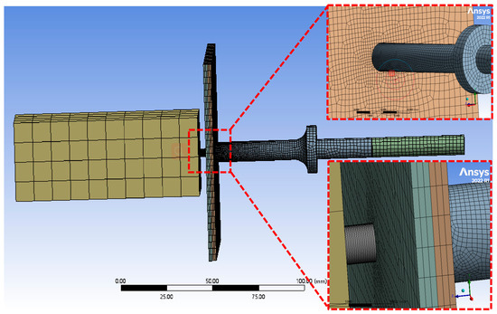
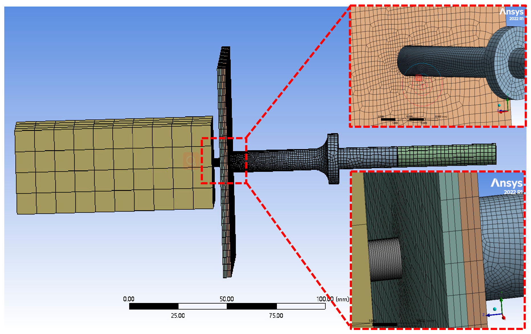
The principle of meshing is to ensure calculation accuracy while minimizing the number of elements to reduce calculation cost. The deformation and stress of rivet and hole are the key concerns in the whole process, and hexahedron mesh division is adopted to improve the accuracy. Due to the complex structure of punch hammer, the mixed grid of tetrahedron and hexahedron is applied to mesh. The mesh around the hole edge was refined, and the element aspect ratio near the hole has approached unity (1:1). A finer grid is divided for the contact area of the rivet, bucking bar and the rivet holes to improve the accuracy of contact calculation. The remaining parts are divided into hexahedron meshes. The mesh division is shown in Figure 6.
Figure 6.
The mesh model.
3.3. Preloading
3.3.1. Constraints and Press Force
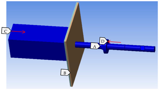
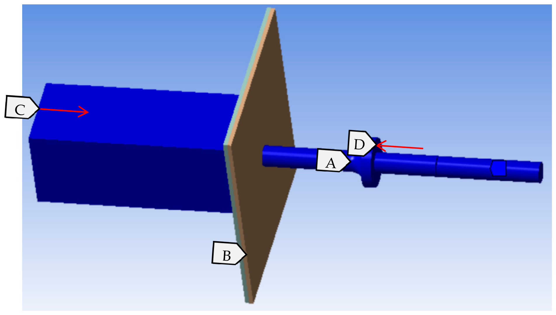
The load and constraint settings of the analysis model are shown in Figure 7, where A represents the rigid body constraint; the bucking bar, hammer, and piston constrain the 5 degrees of freedom except for the Z-direction displacement (their motion direction is in the Z-direction); B is the circumferential fixed constraint of the aluminum plate; C is a press force F acting on the bucking bar to press the rivet; D is a press force F’ acting on the hammer from the riveting gun. The friction coefficient is set as 0.25, all geometric boundaries are automatically identified by the system, and the contact surfaces are assigned a no-penetration contact model.
Figure 7.
The loading of constraints and press force.
3.3.2. Preloading Analysis
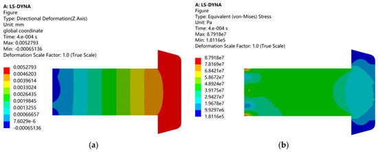
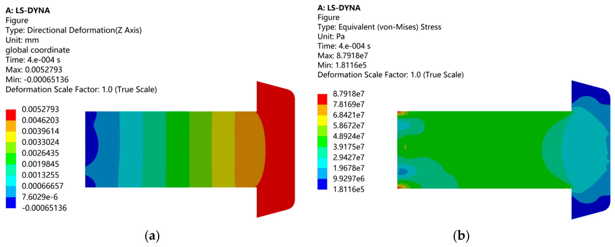
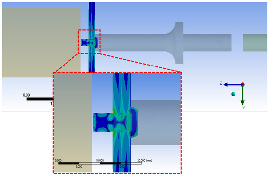
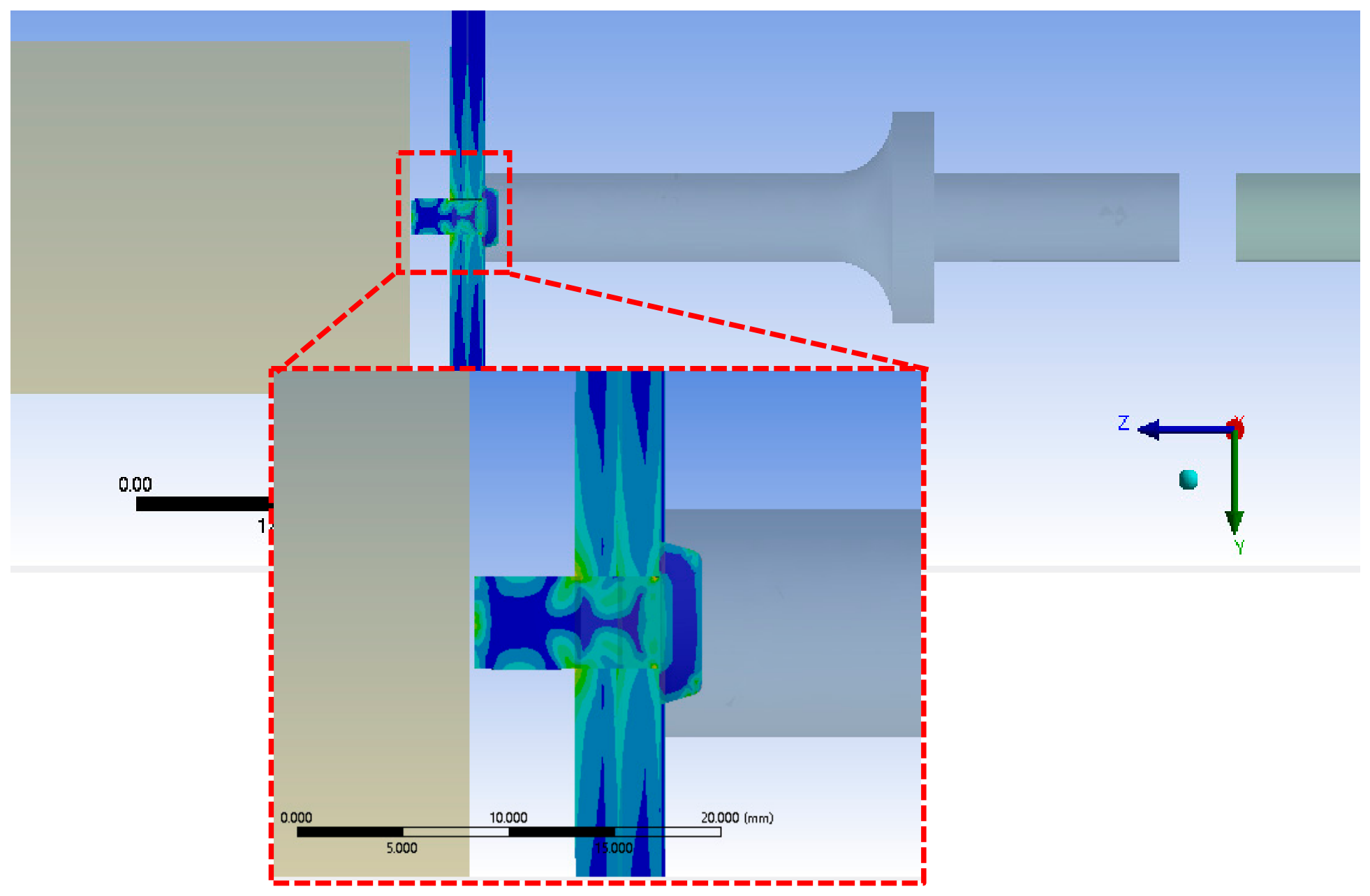
After the modeling, the system is in a preloading static state. The deformation and stress cloud diagram simulated by Ansys is shown in Figure 8. Under the action of a constant preload of 500 N [21], the rivet has a small displacement in Z direction, and the stress under the preload is reflected on the rivet, which is in line with theoretical analysis. In the study by Zhang Kaifu, the rivet was in a state of no internal stress before the first impact [16], which is not consistent with the automatic riveting or human–machine collaborative riveting conditions that require the rivet to be tightened first and then riveted for impact. The force of tightening will generate internal stress on the rivet. So this method is more in line with the real working conditions of human–machine collaborative riveting.
Figure 8.
The deformation and stress cloud diagram of rivet with preload. (a) Z-axis directional deformation; (b) equivalent (von Mises) stress.
3.4. Application of Impact Load
If the riveting impact load is loaded in the form of force, the impact force varies with the time of collision contact, and the variation is determined by the initial velocity and material characteristics. The entire process is complex and difficult to analyze. Zhang Kaifu assumed that the relationship between the time and displacement shift for the moving hammer satisfied of the law of sins, , to obtain the impact input [16]. The initial velocity of rivet hammer was loaded as per the impact load used in the study by Li Yuwen; the velocity was calculated by simulating the movement of the piston inside the riveting gun barrel; the variation in air pressure inside the riveting barrel affects the movement of the piston in a complicated way. The calculation of velocity in this way requires a combination of experiments and simulations.
Due to the fact that pneumatic reciprocating hammer riveting is formed by multiple hammer riveting, LS-DYNA Restart is applied for sequential coupling analysis. In each collision analysis, the initial velocity V of piston is set and it is moved towards the Z+ direction; in the whole impact process, assuming that the piston and rivet hammer are rigid bodies, the deformation can be ignored. Considering that the entire kinetic energy is converted into Strain energy, and ignoring friction force, the energy conversion efficiency is . According to the factory data of the rivet gun, the effective impact energy of the rivet gun can be obtained. Combined with the analysis of the rivet gun model in Section 3, the piston speed is obtained by the following formula:
Referring to reference [19], the impact kinetic energy of the rivet gun at an air pressure of 0.63 MPa is . The mass of the piston, measured experimentally, is . With an efficiency of , the piston velocity is calculated to be .
3.5. Reset Analysis
The riveting simulation model is an un-damped system, and a sudden velocity change in the piston will cause system oscillating, the model will continue to oscillate after the collision. However, during the oscillation stage, global damping needs to be applied to ensure that the entire model stabilizes rapidly; therefore, global damping should be set as magnitude 1000. After each impact collision, both the bucking bar and hammer produce a certain rebound amount under impact loading. Coupled with the upsetting and shortening of the rivet, the clearance between the bucking bar and the rivet gradually increases. To eliminate the oscillation and stabilize the model, the damping is applied to the model. This step is called reset analysis.
4. Results
4.1. Simulation Result Analysis
4.1.1. The Impact Analysis
The displacement cloud of the first impact is displayed in Figure 9. It can be seen that the piston rebounds away from the hammer after collision, and the rivet rod is slightly upset. Due to the impact, both the bucking bar and rivet hammer have a amount of rebound. In addition, the rivet gradually shortens in length during the impact process, resulting in a gap between the bucking bar and the rivet (and as the number of impacts increases, the gap will gradually increase). Therefore, a reset analysis is conducted during this period, and an overall stiffness damping is added to the reset analysis to stabilize the model.
Figure 9.
Displacement cloud plot after first impact.
The stress cloud of the first impact is displayed in Figure 10. It can be seen that two aluminum plates are subjected to compressive stress, with root and head of the rivet rod suffering relatively high stress, causing the rivet deformation.
Figure 10.
Stress contour plot for the first impact.
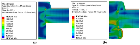
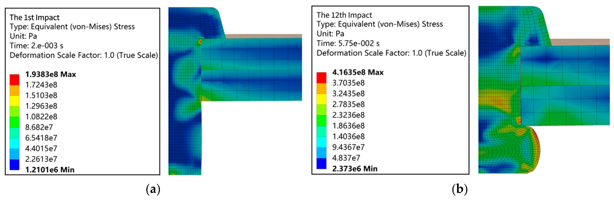
The stress contour plots for the first and twelfth impacts are shown in Figure 11. It can be seen from the analysis results that the red region in Figure 11b exhibits the maximum equivalent stress. This stress level surpasses the yield strength while remaining below the ultimate tensile strength, suggesting that the rivet material in that region has undergone plastic deformation.
Figure 11.
Stress contour plot. (a) The stress contour plot for the first impact; (b) the stress contour plot for the twelfth impact.
4.1.2. The Formation Analysis of the Rivet
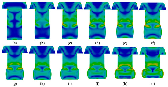
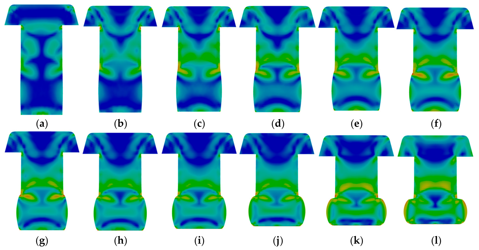
The rivet formation during the riveting process is shown in Figure 12; Figure 12a–l show the equivalent plastic strain contours for the 1st to 12th impacts.
Figure 12.
The formation process represented by equivalent plastic strain contours. Images (a–l) illustrate the upset rivet head forming processes under the 1st to 12th impacts, respectively.
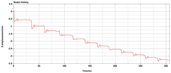
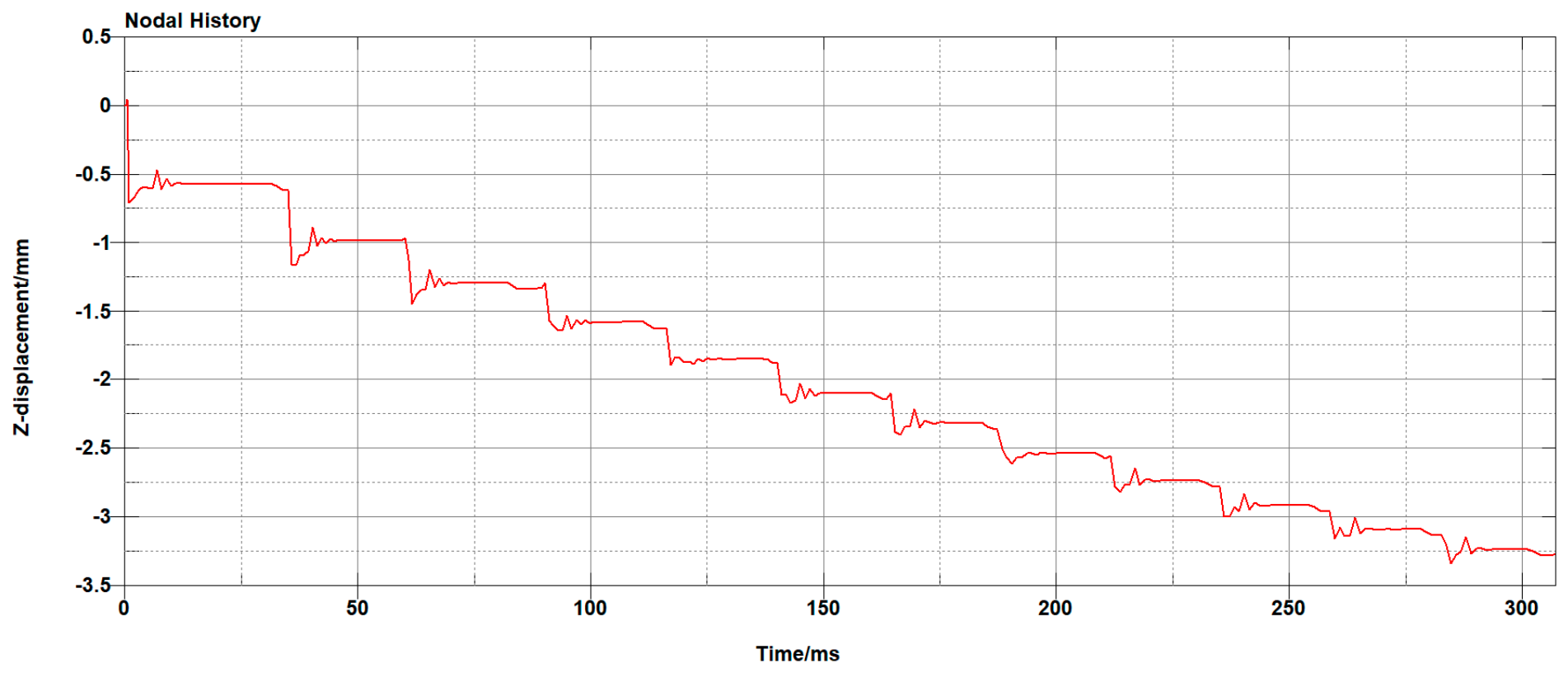
The analysis of the deformation amount of the rivet pier head height is the key to the quality control of riveting. This article selects the element on the rivet tail end to analyze the displacement of the element along the Z-axis during the forming process. From this, the forming height of the rivet pier head can be obtained.
In addition, the deformation values along Z-axes for this element are shown in Figure 13. It can be observed that there are 12 distinct impacts throughout the entire riveting process. Displacement oscillation occurs after each impact, which decays to a steady state under the action of damping.
Figure 13.
The Z−displacement of sample node (No. 66259).
4.2. Experimental Results Analysis
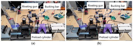
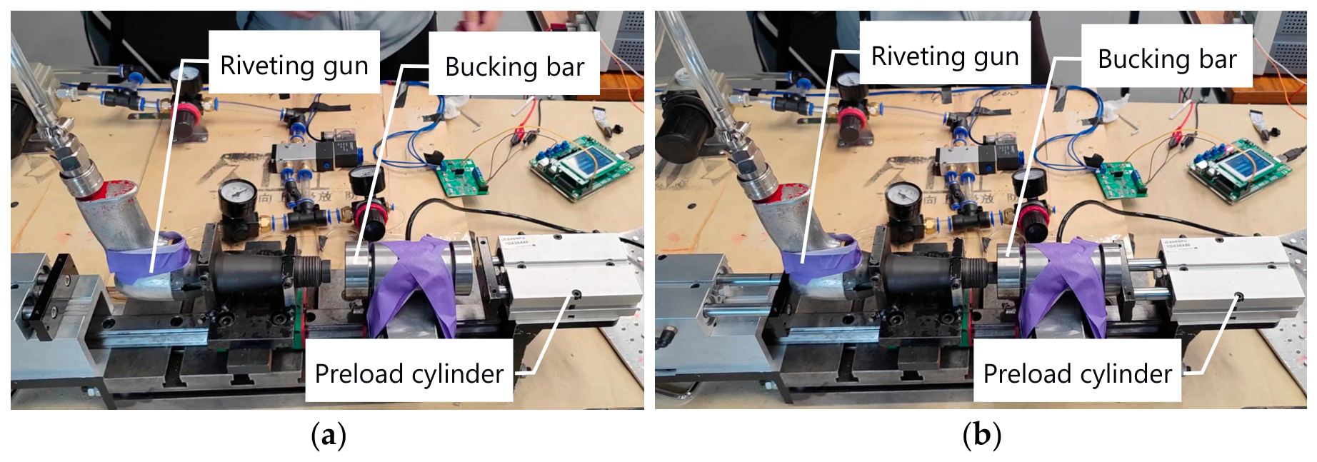
Based on the foregoing analysis, the layout of the conducted experiments is illustrated in Figure 14.
Figure 14.
Human–machine riveting experiment: (a) Separated state; (b) Preload and impact state.
Two experimental sets are proposed in the present work, which are described as follows.
Case 1: The air pressure of the riveting gun was set to 0.63 MPa, the riveting time was set to 0.5 s, and the riveting force signal was collected and studied; the upset head heights are shown in Table 2:
Table 2.
The height of the rivet upset head.
Case 2: The air pressure of the riveting gun was set to 0.63 MPa, and the riveting time ranged from 0.1 s to 1.1 s with an increment interval of 0.1 s. The riveting force and rivet upset head forming conditions are analyzed and listed in Table 3.
Table 3.
The riveting force and rivet upset head forming conditions.
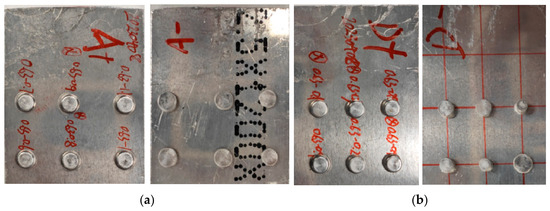
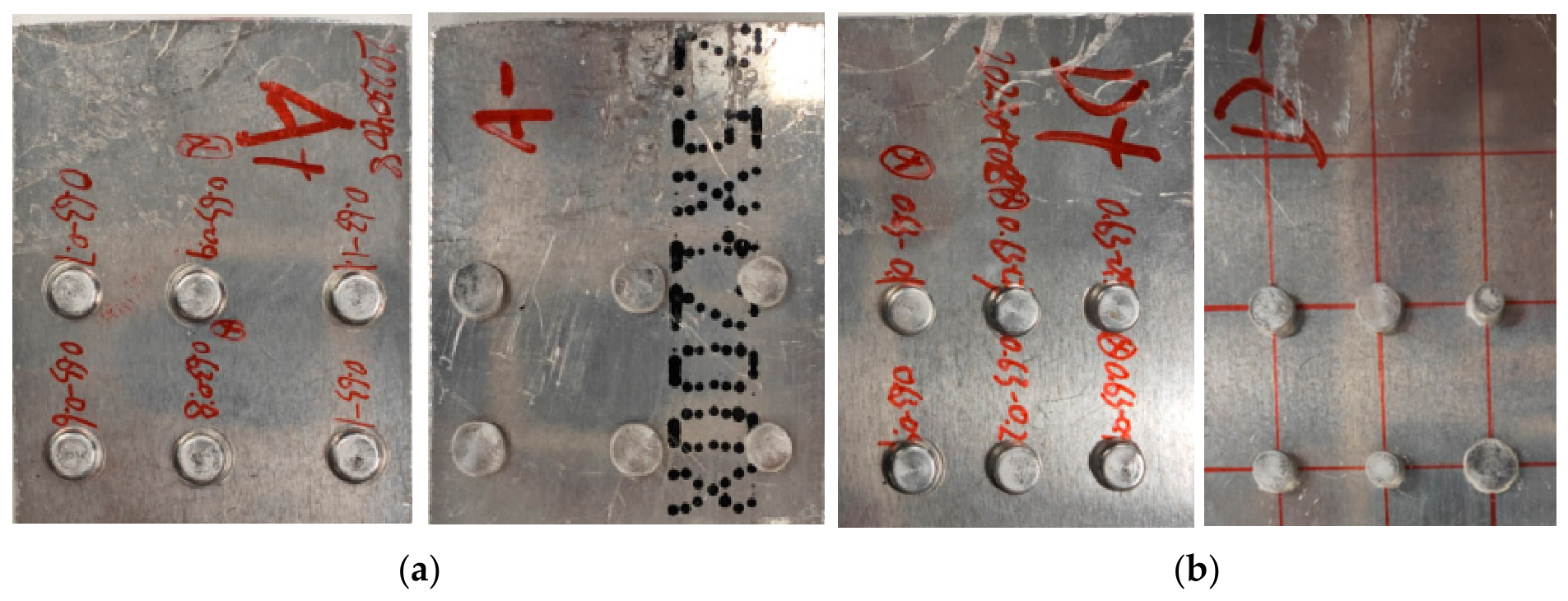
The following two sets of figures (Figure 15) show the upset heads formed in the riveting experiments. In each set, the two images have the rivets arranged in left–right mirror symmetry. A+ and D+ indicate the arrangement of the rivet heads on the front side, while A− and D− indicate the arrangement of the upset heads on the back side.
Figure 15.
Human–machine riveting experiment: (a) upset head dimension comparison for different impact times (0.6 s, 0.7 s, 0.8 s, 0.9 s, 1 s, 1.1 s); (b) upset head dimension comparison for different impact times (0.1 s, 0.2 s, 0.4 s, 0.5 s, 0.7 s, 0.9 s).
It can be observed from the simulation results in Figure 13 that the upset head heights corresponding to 4, 5, 7, 9, and 12 impacts are 3.43 mm, 3.15 mm, 2.68 mm, 2.25 mm, and 1.75 mm, respectively. To quantitatively evaluate the predictive accuracy of the simulation method, we performed a linear regression analysis between the experimentally measured upset head heights and the corresponding simulation predictions. Linear regression between the experimental and simulation results yields a coefficient of determination R2 = 0.945. This high value indicates strong agreement between simulation and experiment, confirming that the proposed method reliably predicts upset head formation despite the inherent stochasticity of the pneumatic riveting process.
5. Discussion
Aiming at the challenge of optimizing process parameters for human–machine collaborative riveting, this paper conducts systematic research on the forming mechanism of pneumatic reciprocating hammer riveting and its simulation analysis method. Combining experimental platform construction, theoretical mechanism analysis, numerical simulation calculation and experimental verification, this work realizes the acquisition of human–machine collaborative riveting process parameters and an investigation into rivet forming laws. The main research conclusions are summarized as follows:
(1) A human–machine collaborative riveting experimental platform is established, and a theoretical study on the operating mechanism of the pneumatic reciprocating hammer riveter is completed. By analyzing the motion law of the internal piston inside the riveting gun, the calculation method for the impact velocity of the riveting hammer piston is clarified. This provides a reliable theoretical basis for the application of loads in subsequent riveting simulations, and addresses the issue that load values adopted in conventional riveting simulations deviate from actual working conditions.
(2) This paper proposes a sequentially coupled numerical simulation method for the riveting process that conforms to actual working conditions. In this method, the impact velocity of the riveter piston is equivalent to the impact load during riveting; the solution and loading of piston impact velocity are realized based on the nominal impact energy of the riveter. Taking the riveting assembly of AL 2024T351 rivets and AL 7039 aluminum plates as the research object, the method achieves high-precision simulation of the entire reciprocating hammer riveting process, and effectively overcomes the drawbacks of low accuracy and poor practical adaptability existing in traditional riveting simulation methods.
(3) Based on the proposed sequentially coupled simulation method and finite element model, simulation analyses of rivet forming under consecutive impacts during riveting were conducted. The complete evolution law of rivet forming was clearly revealed, and it was clarified that rivet forming consists of two core stages: elastic springback and superposed springback of elastic-plastic deformation. The forming characteristics and deformation mechanism of rivet heads under reciprocating hammer riveting were systematically investigated, based on which the optimal riveting process parameters (riveting air pressure, impact time, and bucking force) meeting practical production standards were extracted.
(4) Verification experiments were performed on the self-built human–machine riveting test platform. The measured data show great consistency with simulation results in terms of impact numbers, rivet head height and other indicators, which verifies the reliability of the sequentially coupled numerical simulation method proposed in this paper. The method can provide definite and feasible theoretical guidance and technical support for parameter calibration and scheme design of human–machine collaborative riveting and automatic riveting processes. Future work will conduct a sensitivity analysis to systematically examine the effects of key parameters, including air pressure, preload force, friction, damping, mesh size, and material properties. This analysis will be conducted using a design of experiments (DOE) approach and will be closely coupled with experimental validation on the self-built riveting platform. By comparing simulation predictions with measured upset head geometry and force signals under varied parameter settings, we aim to quantify the relative importance of each factor and to refine the model’s predictive capability.
(5) Furthermore, the proposed sequentially coupled simulation method finite element model can be regarded as a digital twin of the pneumatic percussive riveting process, which contributes directly to the broader goal of assembly quality assurance in aircraft manufacturing. For varying riveting conditions, the proposed methodology can be readily adopted to build the finite element model, assign the impact velocity according to the air pressure, tune the bucking force, and perform multi-impact simulations using the sequentially coupled simulation method, thus enabling the identification and acquisition of suitable riveting control parameters. Similarly, for new and untested riveting conditions, the proposed methodology, which has been experimentally validated, can be applied to simulate and predict the performance of the selected process. The large computational cost (each file > 100 GB) means that performing extensive calculations and predictions for engineering cases requires a large number of computational examples to provide support. This method is more appropriate for large companies or dedicated agencies than for individual users or small groups.
Author Contributions
Conceptualization, J.L. and Y.T.; methodology, J.L. and J.D.; software, J.D.; validation, J.D. and H.Z.; formal analysis, J.D. and M.L.; investigation, H.Z.; resources, W.M. and Y.L.; data curation, Y.L.; writing—original draft preparation, J.L. and Y.T.; writing—review and editing, Y.Z., J.L. and Y.T.; visualization, J.L. and Y.T.; supervision, Y.Z.; project administration, Y.Z.; funding acquisition, Y.T. and J.L. All authors have read and agreed to the published version of the manuscript.
Funding
This research was funded by Science and Technology Department of Sichuan Province, grant number: 2026NSFSC0093, 2026YFHZ0277; Science and Technology Department of Aba, Sichuan Province, grant number R25TJNLJS0001.
Data Availability Statement
No new data were created or analyzed in this study. Data sharing is not applicable to this article.
Conflicts of Interest
Author Junjie Dan was employed by Chengdu Aircraft Industrial (Group) Co., Ltd. Authors Heng Zhao, Weiqiang Mo, and Yi Luo were employed by Leshan Qianchengbei Aviation Technology Co., Ltd. The remaining authors declare that the research was conducted in the absence of any commercial or financial relationships that could be construed as a potential conflict of interest.
Abbreviations
The following abbreviations are used in this manuscript:
| LS | Livermore Software |
| DYNA | Dynamics |
| AL | Aluminum |
| FE | finite element |
References
- Li, Y.W.; Xi, F.F.; Kamran, B. Dynamic Modeling and Simulation of Percussive Impact Riveting for Robotic Automation. J. Comput. Nonlinear Dyn. 2010, 5, 021011. [Google Scholar] [CrossRef] [Scilit]
- Zhang, S. Research on Method and Experiment of Aircraft Pneumatic Percussive Riveting Process Real Time Monitoring Based on Riveting Force. Master’s Dissertation, Shanghai Jiao Tong University, Shanghai, China, 2018. [Google Scholar]
- Peng, S.L. Characterization and ergonomic design modifications for pneumatic percussive rivet tools. Int. J. Ind. Ergon. 1994, 13, 171–187. [Google Scholar] [CrossRef] [Scilit]
- Xiao, M.Z.; Zhu, W.M.; Fan, X.M. A Review on Human-Robot Time-Space Sharing Collaborative Assembly Technology. Aeronaut. Manuf. Technol. 2019, 62, 9. [Google Scholar]
- Xi, F.F.; Lin, Y.; Tu, X.W. Framework on robotic percussive riveting for aircraft assembly automation. Adv. Manuf. 2013, 1, 112–122. [Google Scholar] [CrossRef] [Scilit]
- Li, Y.W.; Ji, J.; Guo, S.; Xi, F. Process Parameter Optimization of a Mobile Robotic Percussive Riveting System with Flexible Joints. J. Comput. Nonlinear Dyn. 2017, 12, 061005. [Google Scholar] [CrossRef] [Scilit]
- Guo, S.; Nie, S.L.; Xi, F.F.; Song, T. Modeling and simulation of percussive impact for robotic riveting system. Adv. Manuf. 2014, 2, 344–352. [Google Scholar] [CrossRef] [Scilit]
- Ahn, J.Y. Methods for Evaluating the Performance and Human Stress-Factors of Percussive Riveting. Master’s Dissertation, University of Washington, Seattle, WA, USA, 2017. [Google Scholar]
- McDowell, T.W.; Christopher, W.; Welcome, D.E.; Dong, R.G. Laboratory and field measurements and evaluations of vibration at the handles of riveting hammers. Ann. Occup. Hyg. 2012, 56, 911–924. [Google Scholar] [PubMed]
- Kadam, R.S. Vibration Characterization and Numerical Modeling of a Pneumatic Impact Hammer. Master’s Dissertation, Virginia Polytechnic Institute and State University, Blacksburg, VS, USA, 2006. [Google Scholar]
- Bloxsom, W.A. Modeling of the Reciprocating, Pneumatic Impact Hammer. Ph.D. Dissertation, University of Nevada, Las Vegas, NV, USA, 2003. [Google Scholar]
- Deng, J.H.; Yu, H.P.; Li, C.F. Numerical and experimental investigation of electromagnetic riveting. Mater. Sci. Eng. A 2009, 499, 242–247. [Google Scholar] [CrossRef] [Scilit]
- Iyer, K.; Rubin, C.A.; Hahn, G.T. Influence of Interference and Clamping on Fretting Fatigue in Single Rivet-Row Lap Joints. J. Tribol. 2001, 123, 686–698. [Google Scholar]
- Szymczyk, E.; Jachimowicz, J.; Sławinski, S.; Derewonko, A. Influence of technological imperfections on residual stress fields in riveted joints. Procedia Eng. 2009, 1, 59–62. [Google Scholar] [CrossRef] [Scilit]
- Blanchot, V.; Alain, D. Riveted assembly modelling: Study and numerical characterisation of a riveting process. J. Mater. Process. Technol. 2006, 180, 201–209. [Google Scholar] [CrossRef] [Scilit]
- Zhang, K.F. Riveting Process Modeling and Simulating for Deformation Analysis of Aircraft’s Thin-walled Sheet-metal Parts. Chin. J. Aeronaut. 2011, 24, 369–377. [Google Scholar] [CrossRef] [Scilit]
- Wang, H.L.; Wang, H. Finite Element Simulation Modeling and Experimental Study of Pneumatic Hammer Riveting Process. Mach. Des. Manuf. 2020, 11, 154–157. [Google Scholar]
- Tian, Y.; Li, J.; Dan, J.; Shu, Y.; Liu, C.; Li, R.; Liu, S. Extracting Technicians’ Skills for Human–Machine Collaboration in Aircraft Assembly. Biomimetics 2023, 8, 604. [Google Scholar] [CrossRef] [Scilit] [PubMed]
- Taranović, D.; Ninković, D.; Davinić, A.; Pešić, R.; Glišović, J.; Milojević, S. Valve dynamics in reciprocating compressors for motor vehicles. Teh. Vjesn. 2017, 24, 313–319. [Google Scholar] [CrossRef] [Scilit]
- Li, J.; Tian, Y.; Dan, J.; Bi, Z.; Zheng, J.; Li, B. Simulation-Based Design and Optimization of Accelerometers Subject to High-Temperature and High-Impact Loads. Sensors 2019, 19, 3759. [Google Scholar] [CrossRef] [Scilit] [PubMed]
- Liu, X.W.; Qian, W. Study on the process of automatic pneumatic hammer riveting. Nonferr. Metal. Mater. Eng. 2017, 38, 154–159. [Google Scholar]

Disclaimer/Publisher’s Note: The statements, opinions and data contained in all publications are solely those of the individual author(s) and contributor(s) and not of MDPI and/or the editor(s). MDPI and/or the editor(s) disclaim responsibility for any injury to people or property resulting from any ideas, methods, instructions or products referred to in the content. |
© 2026 by the authors. Licensee MDPI, Basel, Switzerland. This article is an open access article distributed under the terms and conditions of the Creative Commons Attribution (CC BY) license.