


Abstract
Under the background of the green transformation and energy conservation in the aviation field, hydrogen-fueled aero-engines are the primary direction for achieving sustainable aviation power development. However, the unique thermophysical properties of hydrogen fuel induce extreme thermal load challenges to engine thermal management. Based on the requirements of energy conservation and digital-intelligent technologies, this paper reviewed the recent research progress, important challenges, and future development directions in the thermal management field for hydrogen-fueled aero-engines, and filled the gaps in existing related reviews. (1) As for the liquid hydrogen thermal properties and thermal management requirements, the unique thermal physical properties of liquid hydrogen can easily cause fluctuations in heat load, large temperature differences, and material compatibility issues such as hydrogen embrittlement during storage, transportation, and combustion. The application of thermal barrier coatings, the design of targeted cooling structures, and the regulation of heat loss in the pipeline of the hydrogen supply system require particular attention. (2) As for the technical architecture and optimization of thermal management, the optimization of the high-pressure side manifolds in the cooled cooling air heat exchanger increases the flow uniformity by 18.8% and reduces the weight by 22.5%. The intercooled recuperated engine with the optimum area ratio reduces specific fuel consumption by 5.3% compared to the baseline engine in cruise. However, the system-level optimization research of the above widely recognized solutions is relatively limited in terms of coordinating the energy flow of engines. The baseline engine employed the method of system integration optimization to achieve a 2.99% increase in thrust and a 6.78% reduction in fuel consumption. (3) As for the thermal management modeling and simulation, the intelligent optimization method based on computational fluid dynamics reduces the pressure loss coefficient of the vane-integrated heat exchanger by 36%. Nevertheless, the multiphysics coupling model confronts a contradiction between computational cost and accuracy. (4) As for the comprehensive evaluation method, the advanced configuration of the hydrogen-fueled aero-engine can approximately reduce specific fuel consumption by 68.5% and NOx emission by 12.7% under the same maximum thrust condition. The hydrogen consumption of the proton exchange membrane fuel cells system model compared with the baseline system, optimized by the multi-objective optimization algorithm, has decreased by 15%, while the thermal uniformity has improved by 20–30%. However, the current evaluation system mostly focuses on a single dimension, lacking the analysis of nonlinear coupling among multiple factors and a closed-loop mechanism for evaluation, optimization, and verification. Future research should focus on the matching model of liquid hydrogen’s thermophysical properties and full flight conditions, global multi-energy flows optimization methods, multidimensional collaborative numerical simulation, multiphysics coupling models, and multidimensional comprehensive evaluation systems, to provide closed-loop theoretical support for the efficient, intelligent, and reliable thermal management system for hydrogen-fueled aero-engines.
1. Introduction
The aviation industry’s deep dependence on fossil fuels is a major reason why it is an important global carbon emission source, confronting severe environmental challenges. Hence, exploiting alternative energy sources has become a major trend in the industry’s development. Although alternative fuels such as synthetic kerosene and biofuels have been applied in some scenarios, their limitations—particularly in energy density, large-scale production cost, and emission reduction capability—mean they cannot meet the aviation industry’s demands for low emissions and efficiency. Environmental pressure and concerns over energy security have accelerated the implementation of zero-emission power technologies [1]. In the process of global energy system electrification transformation, intelligent power systems and sustainable energy technologies offer promising pathways to achieve net-zero goals, and the decarbonization of aviation power systems is precisely the crucial link in this transformation [2]. As a new type of clean and efficient energy, hydrogen energy has natural advantages, including zero carbon emission, high energy density, and fast combustion speed. It is an ideal energy carrier for low-carbon development and a crucial trend in the future energy landscape [3]. Applying hydrogen energy in aviation aligns with the principles of clean, efficient, and sustainable development [4]. The hydrogen-fueled aero-engine employs environmentally friendly hydrogen as its primary fuel and converts chemical energy into thermal energy through the intense combustion reaction between hydrogen and air in the combustion chamber, thereby generating thrust. Hydrogen has entered experimental service on regional and short-haul routes and is expected to be adopted widely across all route scales, advancing green aviation transportation. However, hydrogen fuel has thermal characteristics such as high combustion temperature and fast flame propagation speed. These characteristics present thermal coupling challenges in high-altitude, low-temperature, and low-pressure aviation scenarios, as well as crucial technical bottlenecks, including hydrogen storage and transportation. These challenges constitute a complex thermal environment problem, for which an efficient thermal management system (TMS) for aero-engines provides an effective path toward a solution.
The heat and mass transfer processes and energy conversion mechanisms of hydrogen-fueled aero-engines are complex compared to traditional engines. The engine’s thermal management flow is illustrated in Figure 1. Hydrogen is utilized as the core fuel and cooling medium within the engine’s transport pathway, which spans multiple processes including fuel transport, heat exchange, combustion, and propulsion. After being discharged from the cryogenic storage tank, hydrogen fuel flows sequentially through the multi-stage heat exchanger integrated into the engine as an efficient cold source, passing through important nodes such as engine oil cooling, pre-cooling/inter-cooling of compressor air, turbine air cooling, and exhaust heat recovery. The hydrogen absorbs waste heat from the exhaust and compression systems during this process, achieving a liquid-to-gas phase transition and a temperature increase, ultimately entering the combustion chamber in a high-temperature gaseous state [5]. This heating path not only completes the pretreatment of fuel but also fully utilizes hydrogen’s ability as a crucial component of a high-efficiency heat sink cooling engine, achieving effective utilization and recovery of thermal energy.
Figure 1.
Schematic diagram of the engine thermal management process [5].
At the energy conversion level, the components within the hydrogen-fueled aero-engine system achieve the orderly transfer and conversion of energy through tight coupling relationships. The compressor performs work on the intake working fluid during the energy cycle, increasing the pressure and internal energy of the air. Then, the high-temperature and high-pressure gas releases excess chemical energy as heat through the oxidation of hydrogen in the combustion chamber. Next, the gas expands and does work in the turbine, converting thermal energy into mechanical energy to drive the compressor and fan. Finally, the remaining thermal energy is converted into kinetic energy in the exhaust nozzle, generating thrust. The optimized design of the TMS for hydrogen-fueled aero-engines significantly changes the traditional cycle structure.
An aero-engine TMS involves multiple energy forms, including thermal energy, electrical energy, and mechanical energy. The system is designed to comprehensively integrate heat generation, collection, transfer, storage, and dissipation, not only preventing component overtemperature but also enabling rational energy distribution and utilization. Through system-level optimized allocation and dynamic management of thermal energy, the system ensures component reliability at the engine system level, thus improving overall energy efficiency [6,7]. The adoption of advanced aero-engine TMS can significantly enhance comprehensive engine performance and represents a crucial development direction for efficient and energy-saving thermal management technology.
The improvement of power-to-weight ratio and thermal efficiency represents the core development direction for advanced aviation power systems, a principle that applies equally to hydrogen-fueled aero-engines. An efficient TMS serves as one significant technical path to further improve both power-to-weight ratio and thermal efficiency in this context [8,9]. Compared with traditional aero-engines, the new generation of green aviation power systems represented by hydrogen-fueled aero-engines confront complex thermal problems and impose strict requirements on heat transfer and temperature regulation of hydrogen fuel [10]. Liquid hydrogen fuel is stored in cryogenic tanks that require maintaining extremely low temperatures. Moreover, the fuel undergoes a sequence of transport, heating, and flow control prior to entering the combustion chamber. The physical mechanism of this process is highly complex and involves phase change, heat transfer, and flow control of hydrogen fuel. In addition, the control system imposes temperature requirements on the transported hydrogen fuel, as extremely high and low temperatures can cause risks [11]. Therefore, the TMS design is an important element for achieving safe and stable operation of hydrogen-fueled aero-engines.
Advances in computer and intelligent technologies have enabled the utilization of numerical simulation, which accelerates system model construction and accomplishes comparison and optimization of multiple schemes. This approach not only improves the design efficiency and feasibility of thermal management schemes [12,13] but also compensates for the long iteration cycles and high costs associated with experimental methods. Extensive research on thermal management technology for hydrogen-fueled aero-engines has been conducted, and significant findings have been achieved. Such research includes design optimization of advanced thermodynamic cycle architectures [14], research progress in primary component optimization strategies [15], simulation studies of one-dimensional (1D) and three-dimensional (3D) thermal management models [16], and investigations into comprehensive evaluation methods for TMS [17,18]. These works provide an important theoretical basis for developing TMS for hydrogen-fueled aero-engines. Existing reviews have provided comprehensive and systematic summaries of overall schemes for hydrogen-powered aircraft [19], significant component cooling technologies [20], and fuel cell propulsion systems [21]. However, research on TMS design and optimization, as one crucial bottleneck, remains to be synthesized. Therefore, this paper reviews the current state of research on thermal management for hydrogen-fueled aero-engines. Section 2 discusses the thermal characteristics and thermal management requirements of hydrogen fuel. Section 3, Section 4 and Section 5 introduce thermal management technologies and their development, system modeling and simulation, and multidimensional comprehensive evaluation approaches, respectively. Structural flow diagram is shown in Figure 2. This review summarizes the above contents and identifies research hotspots, limitations, and future development directions in the field. The review provides a reference and serves as support for subsequent design and application of TMS for hydrogen-fueled aero-engines and fills an important gap in the current literature.
Figure 2.
Structural flow diagram.
2. Analysis of Thermal Characteristics and Thermal Management Requirements for Hydrogen-Fueled Aero-Engines
The significant temperature difference induced between the cryogenic liquid hydrogen and the high-temperature operating environments of components such as the combustion chamber and turbine results in complex heat transfer paths and concentrated local heat loads. Furthermore, typical aviation operating conditions, system weight constraints, and hydrogen-material compatibility impose distinct requirements on the heat dissipation and insulation of the TMS. This chapter explores three main aspects: the thermophysical properties of liquid hydrogen, differentiated operating conditions, and core constraints, to clarify the design and optimization directions of the TMS for hydrogen-fueled aero-engines.
2.1. Physical and Thermodynamic Properties of Liquid Hydrogen
Liquid hydrogen serves as a highly promising cooling medium for high-temperature components in aircraft power systems due to its specific heat capacity, thermal conductivity, and extremely low boiling point. When flowing through core hot components such as combustor walls, turbine blades, and heat exchangers, liquid hydrogen efficiently removes excessive heat generated during component operation through the coupled effects of phase-change heat absorption and convective heat transfer. This cooling method not only significantly reduces component working temperatures and alleviates thermal stress concentration and material oxidation at high temperatures but also achieves fuel preheating through excess heat recovery, realizing the dual goals of cooling and efficient energy utilization. However, the development of liquid hydrogen cooling technology still confronts numerous difficulties and challenges. These difficulties arise from the substantial property differences between liquid hydrogen and conventional aviation kerosene. Table 1 presents a comparison of primary parameters for the two fuels.
Table 1.
Comparison of the properties of liquid hydrogen and conventional aviation fuel [22].
Liquid hydrogen is often stored in a cryogenic environment. The ultra-low temperature property gives liquid hydrogen an advantage as a cooling medium, but causes low-temperature challenges. The ultra-low temperature environment induces significant cooling deformation changes in pipes and valves, causing a risk of liquid hydrogen leakage. The deformation also alters flow channel cross-sectional dimensions, altering flow distribution and heat transfer uniformity of the cooling medium. When the engine operates under variable conditions, the cooling system must match liquid hydrogen supply flow to component heat load requirements in real time. An excessively large flow leads to fuel waste and piping overpressure, while an insufficient one cannot meet cooling requirements. Hence, complex designs for the fuel supply system and heat exchanger are required under high mass flow demand. Moreover, liquid hydrogen’s high volatility means that any small leakage in the system poses a risk of hydrogen accumulation and explosion, which imposes strict requirements on TMS control throughout the process. Scholars have employed a combination of numerical simulation, theoretical modeling, and experimental validation to comprehensively investigate the difficulties in developing liquid hydrogen cooling technology in recent years. The work provides important theoretical foundations for solving the difficulties in subsequent studies.
Regarding low-temperature challenges during liquid hydrogen transportation, Ye et al. [23] utilized a thermodynamic model to optimize a low-temperature insulation system. The results demonstrate that optimizing the insulation system through material combination and spacer layer configuration enables efficient liquid hydrogen storage. Rompokos et al. [24] indicated that adding a parallel hydrogen combustion module effectively avoids problems caused by low-temperature environments during liquid hydrogen transportation. The parallel hydrogen combustion module, consisting of a gas line and a hydrogen line, primarily serves to regulate cryogenic hydrogen stored in cryogenic H2 tanks to appropriate pressure and temperature levels. The gas line draws air from the engine compression system through a manifold. The air is further regulated by a downstream pressure-regulating valve under off-design conditions. The conditioned air enters a secondary combustor where fuel is burned to raise its temperature before entering an air–H2 heat exchanger and is then discharged through a nozzle. The hydrogen line draws liquid hydrogen from the cryogenic H2 tank and pumps it to an appropriate pressure for subsequent utilization in the engine fuel system, thereby bringing it to a supercritical state. The pumped hydrogen is subsequently heated to a target temperature level by the air-H2 heat exchanger.
Due to hydrogen’s low volumetric calorific value and high specific heat capacity, the flow rates in the fuel and cooling circuits increase dramatically, and a large temperature rise is required. Heat exchangers confront multiple challenges, including high heat load, large temperature difference, and high compactness. Therefore, heat exchanger design is particularly important in TMS. Wen et al. [25] employed hydrogen as a working fluid to study the heat transfer performance of a catalyst-filled plate-fin heat exchanger. The study finds that optimal catalyst-filled plate-fin heat exchanger design helps reduce energy consumption in the hydrogen liquefaction process. Bammoune et al. [26] developed a cylindrical metal hydride reactor tank design that optimized heat and mass transfer in the exothermic hydrogen absorption reaction and improved solid hydrogen storage efficiency via heat exchanger optimization. Experimental results demonstrate that inserting fins into the cooling fluid medium increases both the amount and the rate of heat absorbed by the heat transfer fluid.
Strict requirements for TMS design and control help reduce safety issues during liquid hydrogen transportation. Virdi et al. [27] developed an innovative design for a liquid hydrogen storage, thermal management, and transfer-control system. The design equips each component with a dedicated circulation loop to transfer heat, avoiding added safety concerns due to hydrogen’s high diffusivity and flammability. Armbruster et al. [28] combined 3D computational fluid dynamics (CFD) simulation with experimental data from a single-cylinder engine. The study investigated combustion anomalies and examined the direct correlation between specific combustion anomalies and hydrogen slipping. The results indicate that backfire causes hydrogen leakage and discharges excessive unburned hydrogen directly into the exhaust system, thereby creating explosion and fire hazards. The findings provide an important basis for subsequent research on safety issues arising from abnormal temperatures.
2.2. Important Components and Technologies of TMS for Hydrogen-Fueled Aero-Engines
The cryogenic, volatile, and low-density characteristics of liquid hydrogen render the thermal management experience and analytical frameworks of traditional aero-engines inapplicable. To address the resulting challenges in storage, transportation, and thermal management, it is necessary to clearly define the thermal management requirements of hydrogen-fueled aero-engines. This section focuses on three main aspects: the primary components and their heat flux distribution patterns, the differentiated thermal management requirements under typical aviation operating conditions, and the core constraints of thermal management for hydrogen-fueled aero-engines.
2.2.1. Crucial Components and Heat Flow Distribution Characteristics of TMS for Hydrogen-Fueled Aero-Engines
Figure 3 shows a schematic diagram of a hydrogen-fueled aero-engine. The engine consists of an inlet, a precooler, a fan, a bypass duct, a compressor, a combustor, a high-pressure turbine, a low-pressure turbine, a hydrogen pipeline, and an exhaust nozzle. During flight, the precooler activates, and the low-temperature hydrogen fuel cools the air before entering the combustor for combustion.
Figure 3.
Schematic diagram of a hydrogen-precooled twin-spool mixed turbofan engine [29].
A hydrogen-fueled aero-engine adopts hydrogen as fuel, which has a high calorific value and zero carbon emissions. The engine achieves efficient energy conversion and thrust output through coordinated operation of all components. The compressor is a component that employs high-speed rotating blades to perform work on air, increasing air pressure. The compressor can draw in and compress air to produce high-temperature and high-pressure air for combustion, serving as an important heat source inside the engine. The precooler utilizes liquid hydrogen as a cold source to cool incoming air, ensuring compressor safety and improving cycle efficiency and thrust. The fan accelerates and pressurizes air entering the engine. The combustor mixes high-pressure hydrogen with compressed air for combustion to produce high-temperature and high-pressure gas. The gas requires effective cooling to prevent melting, creep, and oxidation of wall materials caused by excessive gas temperature. The turbines extract energy from the rotation of a high-temperature and high-pressure gas stream and output power to drive the compressor. The exhaust nozzle discharges gas and generates thrust through reaction force. The hydrogen pipeline delivers liquid hydrogen but requires high insulation capability to minimize external heat intake. The valve controls the pressure and flow of hydrogen and provides on/off functionality. The heat exchanger adopts high-temperature air from the compressor to preheat low-temperature hydrogen entering the combustor. This approach not only recovers waste heat and improves engine efficiency but also significantly enhances combustion efficiency. Liquid hydrogen from the storage tank passes through fuel control valves that regulate flow and provide emergency safety shutoff. The liquid hydrogen then enters the precooler located between the inlet and the fan. In the precooler, the hot incoming air flows outside the heat exchange tubes. Through convective heat transfer on the air side, heat is transferred to the tube walls. The liquid hydrogen flowing inside the tubes absorbs heat through convective heat transfer on the hydrogen-side, causing its own temperature to rise sharply and complete gasification. Meanwhile, the incoming air is cooled and then sequentially enters the fan and compressor, which effectively reduces compression component inlet temperature and compression work. After undergoing convective heat transfer, the fully gasified hydrogen leaves the precooler and directly enters the combustor, where it mixes and burns with compressed high-pressure air, releasing chemical energy to generate high-temperature high-pressure gas. Finally, the gas discharges at high speed through the exhaust nozzle to produce core thrust. The bypass flow is discharged through the fan nozzle, generating additional thrust [29,30]. Due to the difference in engine type and flight speed field, heat exchangers can include: (1) a precooler is located between the inlet and the fan for cooling high-speed incoming air to reduce compression work; (2) an intercooler is located between the fan and the compressor or between compressor stages to reduce high-pressure compressor inlet temperature; (3) a cooling air heat exchanger is located between the high-pressure compressor outlet and the high-pressure turbine cooling flow path to reduce turbine cooling air temperature and improve cooling quality; and (4) a recuperator is located between the low-pressure turbine outlet and the exhaust nozzle to recover exhaust waste heat. In an actual engine, not all heat exchangers appear simultaneously. Different architectures select one or a combination according to design goals.
Among the above TMS components, the hydrogen heat exchanger is a core thermal component whose performance directly affects the feasibility and engineering practicability of TMS for hydrogen-fueled aero-engines. The thermal design of a hydrogen heat exchanger is based on classical heat transfer theory, with its core design equations comprising a heat transfer equation and a pressure drop equation, and it requires the selection of an experimentally verified convective heat transfer correlation according to hydrogen’s thermodynamic state. The heat transfer equation is the basis for determining the core parameters of a heat exchanger. The formula is as follows:
where Q is the heat transferred per unit time (W), U is the overall heat transfer coefficient (W/(m2·°C)), A is the heat exchange area (m2), F is the correction factor, and ΔTm is the log mean temperature difference (°C).
Based on the determination of the air-side heat exchange conditions using the classical correlation formula, the specific formula for the hydrogen-side convective heat transfer coefficient given in this paper is as follows:
where , , and are the Nusselt number, Reynolds number, and Prandtl number, respectively. The exponent n is 0.4 when the fluid is heated and 0.3 when the fluid is cooled. A piecewise physical property correction strategy is often employed to improve the prediction accuracy of the heat transfer coefficient in practical engineering design.
The pressure drop constraint is a strict limitation in aviation hydrogen heat exchanger design. The specific formula is as follows:
where Δp is the pressure drop (Pa), f is the friction factor, Lfl is the flow channel length (m), Dh is the hydraulic diameter (m), ρ is the density (kg/m3), and v is the flow velocity (m/s).
Parameters such as heat load, inlet temperature, and liquid hydrogen supply pressure from high-pressure compressor bleed air must be determined before designing a hydrogen heat exchanger. Given the flammable and explosive nature of hydrogen, material compatibility, sealing requirements, and leak-proof structure design must also be considered. Moreover, configuration selection of the hydrogen heat exchanger must comprehensively consider constraints, including working pressure, temperature range, and engine installation space. Three configurations are currently utilized: printed circuit heat exchanger, plate-fin heat exchanger, and microchannel heat exchanger. (1) The printed circuit heat exchanger is suitable for aviation thermal management scenarios with high pressure, high temperature, large heat flux, and space constraints, such as hypersonic aircraft power systems and air-hydrogen precooling heat exchangers in hydrogen-fueled aero-engines. Wang et al. [31] employed the nondominated sorting genetic algorithm II to obtain the Pareto optimal solutions for the design and performance of a supercritical He-H2 printed circuit heat exchanger. (2) The compact fin heat exchanger is suitable for medium-pressure aviation thermal management scenarios such as intercooled recuperated (ICR) cycles and fuel cell air preheating, where lightweight is highly required but pressure tolerance is relatively low. Patrao et al. [32] established conceptual design and aerodynamic optimization of compact integrated heat exchangers and associated ducts and obtained an optimal design scheme for air-side pressure losses and flow uniformity. (3) The microchannel heat exchanger is suitable for extreme aviation scenarios requiring ultra-high pressure, extremely large heat flux, and fast response, particularly for rapid precooling of high-flow air and active thermal protection of reusable aircraft. Bhapkar et al. [33] found that the microchannel heat exchanger has significant advantages in aviation compact heat exchange applications due to its exceptionally high surface area-to-volume ratio. When simulations are performed after preliminary design, problems such as flow non-uniformity, thermal stress coordination, and icing risk must be solved. A trade-off between thermal performance and system power consumption is made during design, and regulation behavior at design and off-design points under various operating conditions is considered. Finally, experiments are conducted to verify the actual heat transfer coefficient and pressure drop of a single heat exchanger core, to test the dynamic coupling characteristics of the heat exchanger with the hydrogen pump and control valve, and to examine the thermal management capability and dynamic response under variable conditions.
Compared with conventional fuel engines, a hydrogen-fueled aero-engine operates at temperatures approximately 150 K higher. The high-temperature and high-velocity primary gas drives combustor wall temperatures up to 2500 K [34], posing significant challenges to the thermal intensity and reliability of components such as the cylinder head, piston, and valves. Moreover, hydrogen combustion yields only water vapor, which is a selectively radiating gas. Wang et al. [35] emphasized that non-uniformity of water vapor at the combustor outlet directly alters the spatial distribution of radiant energy, forming localized high-heat accumulation zones on blades and exacerbating the problem of heat load concentration. However, coupled radiation and non-uniform water vapor distribution induce a thermal ‘self-balancing’ effect through radiation heat flux redistribution, which promotes uniform cooling. Therefore, combustor design for a hydrogen-fueled aero-engine must address the dual heat load challenges arising from local high temperature and enhanced water vapor radiation.
At high rotational speeds, the elevated hydrogen temperature generates an intense heat flux that impinges on the turbine blade surfaces. However, the low-temperature environment at high altitude maintains the non-heated portion of the blade at a low temperature, which further enlarges the temperature difference between the heated and non-heated portions. The resulting constraint on thermal expansion and contraction of the material generates large thermal stress and induces thermal stress concentration at geometric discontinuities. To reduce the risk of thermal stress concentration, Kim et al. [36] employed a thermal-fluid-solid method to study the heat transfer coefficient and thermal stress distribution on turbine blade surfaces. The results indicate that, due to the impingement of incoming gas flow, the heat transfer coefficient is highest at the stagnation point on the leading edge. The lowest heat transfer coefficient appears at the trailing edge on both the pressure side and suction side due to thermal boundary layer development. The highest temperature and thermal stress occur at the trailing edge near the mid-span. Kong et al. [37] studied mist-assisted showerhead steam film cooling on hydrogen-fueled gas turbine blade surfaces. This technology forms a low-temperature protective film near the blade surface, which effectively protects the blade outer surface from direct contact with hot mainstream gas.
Liquid hydrogen stored in a highly insulated container at low temperature and low pressure undergoes vaporization and heating before injection into the combustor. Atomization is a crucial process for rapid and uniform mixing with air. Liquid hydrogen has low viscosity and small surface tension, properties that facilitate atomization into fine and uniform droplets. Such fine droplets evaporate quickly and react uniformly and rapidly with oxidants to form an ideal combustible mixture, achieving efficient and stable combustion. However, pipeline heat loss represents the core challenge affecting atomization efficiency. Lei et al. [38] found that heat loss generates pressure. They reduced the flame tip position, inducing large-scale vortices in turbulent flow and weakening atomization. Palani et al. [39] experimentally demonstrated that increasing the number of nozzle holes indirectly mitigates the negative impact of heat loss, and this approach improves hydrogen atomization efficiency. Lei et al. [40] indicated that heat loss causes deflagration, reducing atomization effectiveness.
2.2.2. Differential Thermal Management Requirements Under Typical Aviation Operating Conditions
Hypersonic aircraft powered by supersonic combustion ramjet engines experience severe aerodynamic heating and thermal loads on wing leading edges, nose cones, and aero-engine combustor walls during supersonic or hypersonic flight through the atmosphere. Without a reliable thermal protection system and thermal control system, high temperatures may alter the fuselage shape, structural strength, and stiffness, and damage onboard avionics. Such changes and damage seriously affect aircraft performance and safety. To meet the military requirements of high speed, long range, and miniaturization, designing an integrated TMS for hypersonic aircraft is essential. This means that the airframe structure, thermal protection system, thermal control system, and propulsion system are designed synchronously in a coupled manner. He et al. [41] indicated that frequent operational shifts, such as take-off and climb, cause drastic fluctuations in engine thermal load, which bring complex control challenges including significant nonlinearities and strong cross-coupling. Liu et al. [42] demonstrated that under high thrust, the engine produces excessive waste heat that requires effective heat dissipation and energy recovery through the TMS.
In the high-altitude, low-pressure, and low-temperature external environment, the reduced air density diminishes the engine’s heat dissipation capacity during cruise. Although this results in a lower thermal load compared to the takeoff phase, components such as the wing leading edge and air intake remain susceptible to icing. The external environment demands protection of components from icing threats, while internal equipment requires effective heat dissipation to prevent thermal shutdown. Balancing heat dissipation and heat preservation is a requirement of TMS to ensure continuous cooling of electronic equipment and maintenance of critical component temperatures. Ke et al. [43] developed an active–passive combined thermal protection structure that integrated insulation material and convective cooling. Compared with a single thermal protection method, the structure achieves the desired effect with a lower coolant flow rate and smaller thickness. Li et al. [44] established the silicone rubber composite reinforced with graphite nanoplatelets exhibiting significant thermal insulation performance, which prolongs ice melting time. Yang et al. [45] designed a TMS equipped with a middle fuel return branch and a recirculation fuel supply branch. The system achieves finer temperature control and enhances heat dissipation capacity.
During landing and idle phases, engine thrust sharply decreases and thermal load reduces. However, due to system thermal inertia, components remain at a high temperature, and the braking system generates substantial heat. The TMS must recover braking energy and waste heat, control component cooling rates, and avoid thermal shock. Waste heat recovery methods capture waste heat from gas or liquid processes and transfer the heat back to the system as additional energy, which can be utilized to generate extra heat, electricity, and mechanical power. Conventionally, a higher temperature means higher waste heat quality and easier optimization of the waste heat recovery process, making high-efficiency waste heat recovery critically important. Xu et al. [46] integrated a lubricating oil vapor compression system, recovering waste heat from the lubricating oil under low-load conditions and significantly improving cabin heating response. Liu et al. [47] utilized waste heat from commercial aero-engine walls to drive a power generation system, achieving fuel cost savings of approximately 3.66% lower than the original fuel consumption.
2.2.3. The Core Constraints of Thermal Management in Hydrogen-Fueled Aero-Engines
The influence of a high-altitude low-pressure environment on the heat exchange efficiency of a hydrogen-fueled aero-engine is significantly complex and interrelated, as low pressure directly reduces air density. This reduction not only weakens the air-side convective heat transfer coefficient in the cooling system and significantly lowers the heat transfer driving force between liquid hydrogen and ambient air, but it also impairs fuel combustion adequacy due to insufficient oxygen supply. The impaired combustion causes uneven in-cylinder heat load distribution and further aggravates operating condition fluctuations of the heat exchange system. Beltrame et al. [48] utilized integrated system design optimization to determine the heat transfer area of the heat exchanger. While satisfying temperature, pressure, and mass flow rate constraints, the work minimizes the increase in heat transfer area, which otherwise directly conflicts with the space and weight limitations of the aircraft. Abreu et al. [49] indicated that wing heat dissipation is mainly affected by temperature gradient and the Reynolds number of the flow. Heating the lower wing surface improves air heat transfer performance during cruise and alleviates the situation of insufficient heat dissipation capacity. Koszut et al. [50] emphasized that in a high-altitude low-pressure environment, the risk of external frost and ice formation persists. Superhydrophobic heat exchangers completely eliminate frost formation, solving the problem that frost accumulation increases thermal resistance and consequently reduces heat exchanger efficiency. Therefore, relying solely on air cooling is insufficient, and other heat dissipation schemes must be introduced.
To meet the core demand for lightweight and efficient development of hydrogen power system equipment, particularly in application scenarios highly sensitive to weight and energy consumption, reducing system dead weight directly alleviates driving power pressure and thereby reduces hydrogen fuel consumption while improving endurance. Meanwhile, weight reduction is accompanied by improved heat transfer efficiency and waste heat recovery, which further optimizes thermal management efficiency. Choi et al. [51] established a new method that combines deterministic approaches based on safety factors with a probabilistic framework for evaluating uncertainties and variabilities. The method effectively overcomes limitations of purely deterministic designs and reduces unnecessary weight gain while ensuring safety. Anibal et al. [52] employed a conjugate heat transfer model to optimize a fin heat exchanger. The optimization not only improves the accuracy of heat dissipation prediction but also reduces the physical size. Zhang et al. [53] optimally combined a heat exchanger with a mass injection device. The combination enhances precooling depth based on the mass injection and simplifies the structure of ultra-compact heat exchangers. The work improves engine performance and optimizes the weight and manufacturing complexity of the precooling system.
Hydrogen can damage certain metals and alloys through hydrogen embrittlement, hydrogen corrosion caused by hydride formation, and cracking induced by internal hydrogen precipitation. Currently, the most common problem in high-strength materials utilized in industries such as aerospace and hydrogen storage tanks is hydrogen embrittlement. Hydrogen embrittlement is defined as a process in which material strength significantly decreases due to the introduction of hydrogen during operation in a hydrogen environment, while material ductility simultaneously decreases, and the material becomes brittle. Austenitic stainless steel has been widely adopted in hydrogen energy production equipment because it is not prone to hydrogen embrittlement, but the problem still appears after a certain period. Both a slow strain rate and an increase in temperature exacerbate the hydrogen embrittlement phenomenon. Current research focuses mainly on reducing hydrogen atom aggregation through microstructural control. Endrös et al. [54] emphasized that microstructure differences in titanium alloy Ti–6Al–4V affect hydrogen interactions. Optimizing the microstructure controls hydrogen distribution, avoids local accumulation of hydrogen atoms, and improves hydrogen embrittlement resistance. Sridharan et al. [55] employed microstructural modifications to prevent hydrogen embrittlement in additive manufacturing fabricated materials, reducing the generation of hydrogen atoms and their penetration into the metal interior. Jiang et al. [56] investigated that modifying irradiation defects in the austenite phase minimizes hydrogen accumulation, thus enhancing hydrogen-induced corrosion resistance of austenitic stainless steels. Yuan et al. [57] established that the composite coating has good hydrogen gas barrier properties and reduces the occurrence of hydrogen embrittlement.
In conclusion, the analysis of the thermophysical properties of liquid hydrogen and the requirements for thermal management is the foundation for researching the TMS of hydrogen-fueled aero-engines. Considering the thermophysical properties of liquid hydrogen and the technical requirements confronted by the TMS under various operating conditions provides a problem-oriented approach for the research on the TMS of hydrogen-fueled aero-engines. Pressure fluctuation, phase transition, and thermal stress concentration induced by liquid hydrogen must receive focused attention. Furthermore, compatibility between hydrogen and materials has not yet been effectively coupled with structural design and thermal protection strategies of the TMS. Based on a thorough understanding of hydrogen fuel thermal characteristics and thermal management requirements, and under stringent constraints of heat exchange efficiency, weight, and material properties, integrated TMS design and efficient flow distribution control can improve component life and energy utilization efficiency, providing important technical support for the engineering application of hydrogen aviation.
3. Thermal Management Technologies and Development for Hydrogen-Fueled Aero-Engines
Traditional aero-engines employ thermal management technology systems primarily focused on regulating cooling air, recovering fuel and lubricating oil, and optimizing thermodynamic cycles. However, the engine’s heat flux distribution and thermal load characteristics are altered by the introduction of hydrogen fuel, which induces challenges to traditional thermal management technologies. This chapter further reviews applicable thermal management solutions, verification progress, and optimization strategies for hydrogen-fueled aero-engines, providing direction for the selection and performance improvement of TMS for hydrogen-fueled aero-engines.
3.1. Conventional Thermal Management Technology for Aero-Engines
Traditional aero-engine thermal management technology has core objectives of improving overall system thermal efficiency, converting heat loads across systems, and realizing thermal cycles. The technology coordinates three technical paths, including regulating cooling air, recovering fuel and lubricating oil, and optimizing thermal cycles, establishing an efficient multidimensional thermal management technology system.
The cooling air system serves as a core component of traditional aero-engine thermal management technology and a significant system for ensuring safe operation of components in the hot end while balancing engine performance and reliability. The crucial target of the system is to extract high-temperature, high-pressure air from engine compressor stages and to provide directional cooling protection for core components under extreme thermal loads, including the combustor, turbine blades, end walls, and vanes, through systematic path design, flow distribution, and precise regulation. By optimizing bleed air extraction, transport, and utilization throughout the cooling process, the system minimizes performance loss caused by compressor bleed air, achieving the goals of maximum cooling efficiency and minimum cooling air consumption. Guo et al. [58] emphasized the importance of cooling air for the secondary air system. Combined adjustment of the primary stream and the secondary air system reduces specific fuel consumption by 3.03% during subsonic cruise and increases engine thrust by 2.03% during supersonic cruise.
Efficient recovery and utilization of fuel and lubricating oil is the core technology for energy recovery in an engine TMS. The conventional fuel and lubricating oil TMS is shown in Figure 4. This technology abandons the traditional mode in which fuel and lubricating oil serve only as working media, and in which waste heat after cooling is discharged directly to the atmosphere. Instead, fuel with large heat capacity serves as the core heat sink and lubricating oil as the auxiliary heat sink. Constructing a heat exchange network achieves overall waste heat recovery and resource utilization. Due to the fuel’s ability to maintain a relatively stable temperature under different flight conditions and experience low loss during thermal energy conversion, the stability of the TMS is significantly enhanced. With the target of achieving heat dissipation protection and performance enhancement, the application of the technology substantially reduces overall engine heat loss and gradually increases waste heat utilization. Yang et al. [59] constructed and improved the fuel heat sink consumption rate model. The aircraft’s takeoff weight is 20.33 kg lower than that of the baseline engine, and maximum flight endurance increases by 11.62%. The work achieves efficient recovery and utilization of thermal loads of fuel and lubricating oil.
Figure 4.
Conventional fuel and lubricating oil TMS [60].
Optimization of the thermal cycle is based on engine cycle design and can overcome the limitation of traditional thermal efficiency. Advanced thermodynamic cycles mainly include the intercooled cycle, recuperated cycle, and ICR cycle. The ICR cycle, when added between compressor stages, reduces compression work and energy consumption, while a recuperator recovers waste heat from high-temperature exhaust gas. Under a stable turbine inlet temperature, preheating the combustor air with the recovered heat reduces the fuel consumption rate. Utilizing an intercooler in the engine to control high-pressure compressor inlet temperature not only reduces energy consumption but also increases the temperature difference between air and gas in the recuperator, improving recuperation efficiency. Crisalli et al. [61] indicated that a gas turbine engine with an ICR cycle system saves 30% fuel compared to a simple cycle propulsion engine. Liu et al. [62] constructed a synergistic heat recovery–dissipation architecture and introduced a helium-based intermediate cycle. The architecture achieves a maximum thermal efficiency of 50.7% and increases specific thrust by about 41%.
3.2. TMS Schemes and Validation for Hydrogen-Fueled Aero-Engines
To significantly improve the volumetric storage efficiency of aircraft hydrogen tanks, hydrogen fuel is mainly stored in a low-temperature liquid state. Liquid hydrogen fuel undergoes a multi-stage temperature rise process before entering the combustor for combustion. This characteristic endows a TMS for hydrogen-fueled aero-engines with unique energy recovery potential and simultaneously drives innovation in the overall TMS architecture. Due to the composite heat sink characteristics induced by the latent heat of phase change in liquid hydrogen and the ultra-high specific heat capacity of gaseous hydrogen, the TMS for hydrogen-fueled aero-engines can overcome the architectural limitations of traditional aero-engine thermal management and establish an integrated system that incorporates fuel preheating, cooling air system, and waste heat recovery. Research directions mainly include thermal management scheme design suitable for hydrogen-fueled aero-engines [63], development of dedicated thermal management technologies, and overall construction of the TMS [30].
3.2.1. Typical Schemes and Architectures for the Thermal Management of Hydrogen-Fueled Aero-Engines
(1) Heat exchanger scheme utilizing hydrogen fuel as the heat sink
Hydrogen fuel serves as the ultimate heat sink, absorbing waste heat from primary components such as the engine oil system and combustor through a heat exchanger, preheating the hydrogen fuel entering the combustor while cooling the components, as shown in Figure 5. This scheme has achieved substantial results in thermal management for hydrogen-fueled aero-engines. However, existing research focuses mainly on improving heat exchanger performance or engine cycle efficiency, and a system-level coupling mechanism between heat exchanger flow resistance and engine energy demand is still lacking. Gomez-Vega et al. [64] employed liquid hydrogen with low temperature and high specific heat capacity as a heat sink and established a tubular heat exchanger model. Compared with a baseline aircraft, the improved model reduces payload-fuel energy intensity by up to 9.8% and reduces engine cruise thrust-specific fuel consumption by up to 7.0%. Gibreel et al. [65] combined wavy wall surfaces with cylindrical fins and circulated hydrogen fuel as a coolant in regenerative cooling channels to absorb combustor wall heat. Compared with a straight-smooth structure, this configuration increases the Nusselt number by 46.89%, reduces maximum wall temperature by 22.71%, and increases the thermal performance factor by 43.33%, while the friction factor increases by only 3.64%. In summary, although this scheme offers advantages in heat transfer and drag reduction, the thermal management coupling issues arising from hydrogen embrittlement risk and fuel temperature rise still affect the engineering applicability of TMS for hydrogen-fueled aero-engines.
Figure 5.
Schematic diagram of an engine architecture utilizing hydrogen fuel as the heat sink [66].
(2) ICR Scheme
The ICR scheme places an intercooler between compressor stages and adopts low-temperature hydrogen as a cold source to cool compressed air, reducing high-pressure compressor work. A recuperator is installed at the exhaust end to further preheat hydrogen or air entering the combustor by utilizing exhaust waste heat, thereby improving engine cycle thermal efficiency, as shown in Figure 6. Introducing the ICR scheme from conventional fuel aero-engines into hydrogen-fueled aero-engines for preheating offers significant advantages. In the engine cycle, low-pressure compressor discharge air temperature ranges from 344 K to 398 K, and exhaust gas temperature at the recuperator inlet ranges from approximately 704 K to 849 K, providing sufficient thermal energy for hydrogen fuel preheating [32]. The ICR scheme recovers waste heat to improve overall engine thermal efficiency without requiring an additional heat source. Abedi et al. [30] designed and optimized a compact heat exchanger for a hydrogen-fueled aero-engine and developed a numerical framework to model hydrogen-fueled gas turbine engines. Targeting heat load, temperature rise, and energy loss in the compression system, the study proposed a system that integrated a heat management scheme that combines liquid hydrogen storage, gasification, compression system heat dissipation, and heat recovery. An intercooler and a recuperator are arranged in the compression system to recover and utilize heat and thereby improve engine performance. Kozakiewicz et al. [67] established an ICR turbofan model typical for narrow-body aircraft engines. Comparing the performance of the model with a baseline engine, the study indicates that specific fuel consumption is reduced by 5.2%, NOx emissions are reduced by more than 21%, and turbine inlet temperature is increased by about 9 K.
Figure 6.
Schematic diagram of a turbofan engine with an ICR scheme [67].
(3) Hydrogen fuel precooled scheme for cooling air
The low-temperature characteristics and thermodynamic properties of hydrogen fuel provide a unique cold-source advantage for aero-engine cooling systems. The hydrogen fuel precooled scheme for cooling air employs a precooler placed before the inlet or low-pressure compressor to directly cool incoming air through the large heat absorption capacity of liquid hydrogen vaporization. This approach not only greatly reduces air temperature and increases air density and flow rate but also enhances engine thrust, as shown in Figure 7. The cooling air system and the bypass duct heat exchanger design optimization have achieved substantial results. However, existing research focuses mainly on cooled cooling air heat exchangers’ performance alone, and a coupling mechanism between flow resistance and engine performance at the engine system level has not been revealed or applied to hydrogen fuel engine systems. Kallath et al. [68] studied the influence of flow uniformity in high-pressure side manifolds on the aerodynamic and thermal performance of a cooled cooling air heat exchanger. After optimizing inlet and outlet manifold geometries, the work achieves an 18.8% improvement in flow uniformity, a 10.6% reduction in pressure drop, a 0.4% increase in heat transfer rate, and a 22.5% decrease in weight. Pandey et al. [69] established porous media and dual-cell heat exchanger models under non-uniform inflow conditions. The results indicate that flow non-uniformities symmetric in the horizontal plane enhance the heat transfer rate of a cooled cooling air heat exchanger, whereas asymmetric non-uniformities reduce the heat transfer rate. Liu et al. [70] investigated that after applying a cooled cooling air heat exchanger and with a single-sided plate-fin heat exchanger under the same heat transfer conditions, the pressure drop of bypass duct air is reduced by more than 50% compared with a conventional serpentine-tube heat exchanger. Total engine thrust increases by approximately 51.5%, and specific fuel consumption reduces by 33.4%.
Figure 7.
Schematic diagram of the engine model utilizing cooled cooling air technology [71].
3.2.2. Experimental Validation of Precooled, Intercooled, and Recuperated Schemes
(1) Validation of the intercooled scheme
The intercooled scheme employs the high specific heat capacity of hydrogen fuel as an interstage heat sink to absorb compression heat between compressor stages, reducing interstage temperature and compression power consumption. However, the intercooler introduces flow resistance and weight penalties. Patrao et al. [72] applied a compact heat exchanger integrated into an intermediate compressor duct to a hydrogen-fueled turbofan engine. The results demonstrate that compared with a non-intercooled reference, the hydrogen engine with this scheme reduces specific fuel consumption by 3.9% during takeoff and by 2.7% during cruise. Moreover, the intercooled scheme reduces air-side total pressure drop from 8–9% to as low as 4.35%. Miltén et al. [73] found that an intercooled scheme provides far greater cooling potential and achieves lower mass and volume than that achievable by utilizing only fan discharge air. The anticipated improvement in cooling capacity further reduces mass, thermal load, and NOx emissions of piston engines, surpassing levels attainable with conventional air-to-air intercoolers. In summary, the intercooled scheme adopts the high specific heat capacity of hydrogen fuel to achieve dual improvements in fuel consumption and pressure loss. However, the effects of intercooler weight, thermal load, and NOx emissions on a TMS for hydrogen-fueled aero-engines still require further experimental validation.
(2) Validation of the recuperated scheme
The recuperated scheme employs hydrogen fuel’s excellent heat transfer characteristics to recover turbine exhaust waste heat in the recuperator for preheating the combustor inlet working fluid. Zhang et al. [74] investigated recuperator performance improvement at the engine level for the recuperated scheme. The results indicate that compared with a simple cycle, the recuperated cycle reduces the specific fuel consumption of a hydrogen-fueled engine by up to 41%. Tank gravimetric efficiency and recuperator thermal effectiveness are identified as crucial parameters affecting system weight loss. However, the energy-to-revenue work ratio loss of the hydrogen recuperative architecture exceeds 18% relative to a kerosene baseline. Liu et al. [62] demonstrated that when the turbine inlet temperature increases from 1550 K to 2200 K, the recuperator exhibits the largest increase among heat exchangers, with a heat exchange rate increase of about 41%. In summary, the recuperated scheme reduces fuel consumption at the cost of sacrificing conversion efficiency from fuel energy to available work.
(3) Validation of the ICR Scheme
The ICR scheme adopts the high specific heat capacity and strong cooling capability of hydrogen fuel to achieve wall cooling of hot-end components and waste heat recovery. However, applying the scheme in an engine presents challenges such as high experimental cost, complex system integration, and risks of hydrogen leakage and combustion. These challenges lead to limited experimental validation in this research direction. Currently available component-level experimental validation comes from Pratt & Whitney’s project for a hydrogen steam-injected, inter-cooled turbine engine, which conducted tests on a condenser, an evaporator, and a single-nozzle combustor [75]. The results indicate that compared with a baseline geared turbofan engine, the scheme achieves a 99.3% reduction in NOx emissions and a 35% improvement in energy efficiency. In numerical simulation validation, Xin et al. [76] utilized a coupled model based on the Brayton Cycle to analyze and verify the effectiveness of the ICR scheme. The results demonstrate that peak wall temperatures of the exhaust nozzle and afterburner of the hydrogen-fueled engine are controlled at 897.5 K and 869.2 K, respectively, both far below the service temperature limit of 1600–1800 K for hot-end materials. Moreover, the engine’s net output power increases by 9.8% compared with a recuperated scheme. Patrao et al. [32] investigated the ICR scheme employing an integrated design of a compact heat exchanger and a recuperator in an engine system model. The results indicate that under a 3000 nautical mile design mission, total fuel burn is reduced by 5.5% relative to a baseline engine, with specific fuel consumption decreasing by 6.8%. However, the weight added by the heat exchanger and piping increases fuel consumption by 1.4%. Additionally, hydrogen heated by both the intercooler and the recuperator reaches 771 K at the top-of-climb, which is about 400 K higher than in an intercooled scheme. However, they clearly pointed out that the risk of hydrogen leakage and uncontrolled ignition in the compression system is a serious obstacle that the ICR scheme faces when conducting experimental verification on hydrogen-fueled aero-engines. In summary, although numerical simulations have demonstrated the potential of the ICR scheme for thermal protection and energy saving in hydrogen-fueled engines, further system-level experimental validation is still required to address long-term reliability, icing risk, and system integration penalties under actual aviation conditions.
(4) Validation of the pre-cooled scheme
The precooled scheme employs liquid hydrogen as a cold source to directly cool high-temperature intake air at high Mach numbers, expanding the flight envelope. However, the large temperature difference between the precooler inlet air and liquid hydrogen exposes the heat exchanger to risks such as thermal stress and icing. Sato et al. [77] conducted a system firing test. Liquid hydrogen flows sequentially through the precooler and the nozzle wall for regenerative cooling before final combustion in an afterburner. To examine the performance of the engine with the precooler under real flight conditions, a small-scale model of the precooled turbojet engine operates for 30 s at approximately Mach 2. Moreover, a core-engine test under high-altitude conditions verifies that the engine can ignite and function normally under windmill conditions, establishing a technical foundation for subsequent high-altitude tests of an engine incorporating a precooler. Taguchi et al. [78] simulated flight conditions at Mach 4. When the precooler inlet air temperature reaches 900 K, liquid hydrogen cooling reduces the outlet temperature to approximately 430 K, achieving a temperature drop of 470 K with a pressure loss of only 3.6%. The core engine and afterburner achieve stable combustion. Furthermore, the starting sequence of engine components under precooling conditions remains effective, and the precooling effect causes no damage to the rotating parts of the core engine. However, while the experiment remains at the ground simulation stage, the issue of dynamic fuel flow adjustment during flight remains unverified. Additionally, the evolution of wet-air icing and anti-icing strategies under real flight conditions lacks substantial experimental support.
In summary, the intercooled and recuperated schemes focus on improving thermal efficiency, and their technical advantages require investigation and validation over longer flight mission profiles. The precooled scheme concentrates on expanding the flight speed envelope and has clear high-speed flight application scenarios, thus receiving greater investment in engine validation. As thermal management technologies for hydrogen-fueled engines continue to develop, the above schemes are expected to progress toward higher maturity levels.
3.3. Optimization Strategies for the Thermal Management of Hydrogen-Fueled Aero-Engines
Thermal management optimization for a hydrogen-fueled engine is a multidimensional collaborative technology system that encompasses structural optimization, system integration optimization, material innovation, and intelligent optimization. The core goal of the system is to address significant issues caused by the high combustion rate and low ignition energy of hydrogen fuel, such as excessive local heat load inside the cylinder, uneven heat distribution, and a tendency to form hydrogen-rich zones. Through the coupled matching of multiple technical paths, the system achieves precise regulation of heat flow, efficient utilization, and a balance of system thermal safety.
In the thermal management optimization system for a hydrogen-fueled engine, structural optimization plays an important role in improving fuel utilization efficiency, suppressing abnormal combustion, and extending engine service life. The design of the intake port on the cylinder head affects not only charging efficiency but also the temperature distribution and heat dissipation capacity of the combustor. Due to hydrogen’s fast combustion speed, strong diffusivity, and low ignition energy, improper port design can easily create local high-temperature zones in the combustor, which in turn cause knock, backfire, and even material thermal fatigue. Marini et al. [79] optimized intake port geometry for a two-stroke opposed-piston hydrogen engine to control in-cylinder turbulence. Combined with a water injection strategy to suppress pre-ignition, the optimization effectively improves the feasibility of thermal management operation. Breda et al. [80] performed integrated structural optimization of the intake duct and injector cap. They adopted a 3D CFD method for hydrogen/air mixing in the combustion chamber to optimize the intake port geometric parameters and injection direction. This optimization improves mixture uniformity and reduces in-cylinder local high temperatures and thermal load fluctuations. Intake port design must balance air organization, cooling path, and structural strength. Optimizing the piston cooling gallery structure is essential for improving overall system reliability and durability. Xiong et al. [81] designed different oil gallery shapes. Experimental results indicate that fluid flow in a wave-shaped cooling gallery is most stable. Fluid erosion on the gallery walls is most uniform, and heat transfer performance is optimal.
Under the complex and variable thermal load conditions of a hydrogen-fueled engine, multi-cycle coupled thermal management has become an important research direction for improving system reliability. Liu et al. [42] combined a novel hydrogen-fueled turbine engine architecture with a power generation fuel TMS, enabling coordinated utilization of liquid hydrogen’s chemical and physical properties while delivering additional power to the high-pressure shaft. Through thermodynamic coupling modeling and parameter analysis under multiple flight conditions, the study indicates that the presented engine architecture achieves a 2.99% increase in thrust, a 3.99% reduction in fuel consumption, and a 3.4% improvement in overall engine power efficiency compared to a baseline engine. Romagnuolo et al. [82] integrated a hydrogen fuel system with multiple heat exchangers, where hydrogen sequentially served as a cooling medium to absorb heat from the compressor, fuel oil, exhaust gas, and turbine cooling air. This integration achieves multi-source coupled thermal management, enables waste heat recovery and utilization, and ensures system safety. Therefore, in system-integrated thermal management strategies, a multi-cycle coupling approach can realize collaborative optimization of the cooling system, lubrication system, and combustion control system.
Due to the high combustion rate characteristic of a hydrogen-fueled engine, local high temperatures and uneven heat load distribution easily occur inside the cylinder. Moreover, the high concentration of water vapor generated by hydrogen combustion aggravates corrosion of hot-end components. Therefore, aviation application scenarios impose multiple stringent material requirements, including thermal insulation, lightweight, and resistance to hydrogen and oxygen corrosion. The development and application of new materials should achieve precise thermal insulation, efficient thermal protection, and thermal stress mitigation for engine core components, while maintaining lightweight and stability in a hydrogen environment. This approach not only addresses the primary issues of high thermal load and high corrosion in hydrogen engines but also serves as a focus for improving thermal efficiency, operational reliability, and service life. It also provides essential material support for the engineering and multi-scenario deployment of hydrogen power systems. The application of thermal barrier coatings has become a significant technical pathway for enhancing thermal management performance and material durability. Hundreds of different coating types protect various structural engineering materials from corrosion, wear, and erosion, and also provide lubrication and thermal insulation. Yao et al. [83] experimentally and numerically investigated the thermo-structural performance of ω-shaped diesel engine pistons coated with 8 wt% yttria-stabilized zirconia nano-thermal barrier coatings. The results indicate that thermal barrier coatings increase piston top temperature by 90 °C while reducing substrate temperature by 28–48 °C, thereby decreasing heat flux transferred to the piston substrate. Thermal stress analysis reveals that thermal barrier coatings significantly reduce stress in the piston substrate. Peak equivalent and shear stresses occur at the ceramic-bonded coating interface, increasing the risk of cracking. Maev et al. [84] employed cold spraying technology to design and fabricate a multilayer composite coating integrating a multilayer thermal barrier, interface bonding, and catalytic functions. By optimizing the multilayer coating ratio and important cold spraying process parameters, the approach resolves coating thermal stress issues commonly induced by traditional thermal spraying processes, providing a novel coating solution for optimizing and enhancing engine TMS performance.
The dynamic characteristics of the TMS for a hydrogen-fueled engine are closely related to the strong coupling with hydrogen fuel combustion, the randomness of operating condition changes, and the performance degradation of some components. The traditional method based on preset thresholds can no longer achieve precise regulation of heat flow under complex operating conditions. A big-data optimization method for TMS provides a new approach to breaking through the technical bottleneck of adaptive control in TMS. Wen et al. [10] addressed the problems of insufficient architecture adaptability and uneven thermal load in the TMS for hydrogen-fueled aero-engines. An improved genetic algorithm was utilized to perform multi-variable optimization on significant architecture parameters, including the system cooling loop, heat exchanger layout, and waste heat recovery. The results indicate that compared with a baseline engine, the optimized engine achieves a 3.4% increase in exergy efficiency while satisfying core component temperature drop requirements and thermal load balancing. The results verify the feasibility and superiority of the improved algorithm for optimizing hydrogen engine thermal management architecture. Virdi et al. [27] established an integrated liquid hydrogen storage, thermal management, and transfer-control system. The system has intelligent sensing and autonomous control capabilities. It not only supplies on-demand fuel flow at each flight stage by monitoring tank pressure in real time but also independently adjusts each cooling circuit flow according to power demand changes, achieving precise thermal management of crucial components. Chen et al. [85] employed the Twin Delayed Deep Deterministic Policy Gradient deep reinforcement learning method to conduct real-time modeling of a kerosene-fueled high-flow dual variable cycle engine across its full flight envelope. The results demonstrate that this method achieves a single-step simulation time of less than 3 ms, verifying the feasibility of the deep reinforcement learning approach in the real-time modeling of highly nonlinear aircraft engine systems. Alipour Bonab et al. [86] adopted a deep learning-based surrogate model to predict the alternating current losses of superconducting propulsion motors in hydrogen-powered cryo-electric aircraft. The results indicate that the model achieves a prediction time of less than 9 ms with a prediction accuracy of 99.97% and is capable of predicting both the cycle-averaged alternating current losses and the time-varying morphology of instantaneous alternating current loss waveforms. Yu et al. [87] pointed out that safe reinforcement-learning approaches have shown promise in improving decision quality and adaptability under dynamic conditions during real-time operations on modest onboard hardware. The aforementioned intelligent algorithms demonstrate application potential for real-time thermal management control. However, the main reasons why the above algorithms have not yet undergone flight verification are the lack of a long-term ground hardware-in-the-loop environment and a complete dataset of dynamic thermal loads. In summary, Table 2 presents the technical paths and effects of thermal management optimization strategies for hydrogen-fueled engines.
Table 2.
Optimization strategies and applications of thermal management for hydrogen-fueled engines.
In conclusion, the thermal management technology architecture and optimization strategies are crucial paths for the design and optimization of the TMS for hydrogen-fueled aero-engines. Revealing the limitations of the typical system architectures, mainstream schemes, and optimization strategies under complex conditions clarifies the technical optimization direction for the research on the TMS of hydrogen-fueled aero-engines. However, systematic theoretical support and experimental validation are still lacking the deep integration of multiple schemes, such as ICR and air precooling, for assessing the reliability and durability of important components under real operating conditions, and for developing intelligent control strategies to handle thermal load fluctuations and provide thermal protection under varying conditions. Future breakthroughs are required in developing multi-scheme collaborative design methods, conducting long-term ground assessments and flight validations of significant components, and establishing intelligent control integrated architectures for global energy regulation. These advances support the continued development of hydrogen-fueled aero-engines toward high efficiency, reliability, and low carbon, ultimately achieving precise regulation of engine heat flow, efficient energy recovery and utilization, and dynamic balance of system thermal safety.
4. Advances in Modeling and Numerical Simulation of TMS for Hydrogen-Fueled Aero-Engines
Numerical simulation methods can analyze the heat load distribution of hydrogen-fueled engines and the matching characteristics of TMS during the design phase, reducing the costs and cycles of experimental iterations. The selection of numerical simulation software and its multiphysics coupling capabilities affect the prediction accuracy and development efficiency of the TMS for hydrogen-fueled aero-engines. This chapter discusses three main aspects: the current application status of modeling software, multi-level numerical simulation methods ranging from 1D to 3D, and the progress of steady-state and transient multiphysics coupling models, providing methodological references for the simulation analysis of TMS.
4.1. Numerical Simulation Software for TMS in Hydrogen Fueled Aero-Engines
Modeling and simulation of thermal management for hydrogen-fueled aero-engines serves as an important technical approach for achieving efficient and safe operation. Compared with experimental methods, modeling and simulation offer advantages such as low cost, short cycle time, and capability for extreme-condition simulation. However, simulation results still require experimental validation. Combining the two approaches ensures high precision while accelerating system development. As hydrogen power technology advances, the TMS involves multidisciplinary fields such as fluid dynamics and control theory, which significantly increase modeling complexity. Various numerical simulation software tools are widely utilized to construct a model of TMS for hydrogen-fueled aero-engines, enabling design optimization and performance prediction of such systems.
The modeling methods of thermal management for hydrogen-fueled aero-engines exhibit diversified characteristics. Madia et al. [88] adopted Simcenter STAR-CCM+ 2310 to establish flamelet combustion models for hydrogen-fueled internal combustion engines, enabling prediction and simulation of heat transfer and combustion under various engine loads. The results indicate that the model accurately and stably predicts the hydrogen combustion process and associated thermodynamic behavior while reducing calibration effort. Cai et al. [89] employed ANSYS Fluent 2021 R2 to establish a numerical model for multi-fuel multi-channel micro-combustor architectures. The study demonstrates that a dual-channel combustor and a quad-channel combustor significantly increase mean outer wall temperature and temperature uniformity compared with a single-channel combustor. Chai et al. [90] constructed a combustion chamber simulation model employing CONVERGE to evaluate the performance of a port fuel injection heavy-duty hydrogen-fueled internal combustion engine. The model enables systematic simulation analysis of excess air coefficient, engine performance, and emission characteristics. The results indicate that increasing the excess air coefficient substantially reduces NOx emissions. Coordinated control of air coefficient and spark timing optimizes the trade-off between emissions and thermal efficiency. Serrano et al. [91] utilized GT-Suite to build a comprehensive 1D engine model, enabling performance evaluation of hydrogen engine torque and efficiency across the full load range. The study demonstrates that a two-stage turbocharging system combined with direct injection technology effectively improves hydrogen engine performance. Fenner et al. [92] utilized Flownex SE 2022 to establish a coupled model of thermal fluids and a chemical reactor network, predicting the combustion chamber performance of hydrogen–propane mixed fuel in gas turbines. The study demonstrates that an increase in the hydrogen mixing ratio significantly enhances the reaction zone temperature and NOx generation rate, and alters the temperature distribution and flame position within the combustion chamber. Romagnuolo et al. [82] employed Simcenter Amesim to establish a lumped parameter model for the fuel system of a hydrogen-powered aircraft turbine engine, achieving multi-stage heat exchange in the main liquid hydrogen loop to vaporize and heat the hydrogen fuel. The results indicate that during the steady state phase of the takeoff condition, the system can stably supply 51.55 bar, 353 K, and 0.411 kg/s of hydrogen fuel to the fuel metering unit inlet, and the total heat power provided by the heat exchanger is 2.110 MW. Nazri et al. [93] utilized SolidWorks 2022 to conduct static structural and steady-state thermal analyses on a cryogenic hydrogen storage tank for a Cessna 172 light aircraft. The results indicate that, under identical geometric dimensions, storage pressure, and thermal load conditions, the aerogel-insulated configuration exhibits a significantly lower total system mass (approximately 15.9 kg) and hydrogen boil-off rate (3.6 g/h) compared to the fiberglass-insulated configuration (approximately 38.9 kg and 2019.2 g/h, respectively), with a much lower heat flux (0.2223 W/m2) than that of fiberglass (15.4 W/m2), demonstrating superior thermal insulation performance. Liu et al. [42] developed a TMS simulation model library adopting MATLAB. A thermal dynamic simulation model of TMS for a fighter was built to investigate the influence of fuel temperature on fuel TMS performance, enabling dynamic monitoring of crucial node temperatures under a flight mission profile. The study demonstrates that a large return fuel flow rate or a small amount of fuel in the fuel tank causes a rapid fuel temperature rise inside the tank. Current modeling software for TMS of hydrogen-fueled aero-engines indicates a trend toward multi-platform collaboration and multi-scale coupling. Existing models achieve dynamic regulation and energy efficiency optimization of TMS, but high-fidelity dynamic models for full life cycles and extreme environments still require further development. Table 3 summarizes the commonly employed numerical simulation software for integrated thermal management of hydrogen engines.
Table 3.
Commonly adopted numerical simulation software for integrated thermal management of hydrogen engines.
4.2. Numerical Simulation Methods for TMS in Hydrogen-Fueled Aero-Engines
Complex interactions exist among low-temperature fuel heat absorption, high-speed flow, and combustion reactions in TMS for hydrogen-fueled aero-engines. Single-dimensional numerical simulation techniques alone cannot fully capture the thermal characteristics. One-dimensional methods focus on system-level thermal balance and component matching. Two-dimensional methods suit heat-flow coupling analysis in simplified geometries. Three-dimensional methods precisely capture local heat and mass transport details. Multidimensional coupling methods enable data transfer and collaborative computation across dimensions, realizing performance evaluation and feasibility validation of TMS for hydrogen-fueled aero-engines from the component level to the system level.
Regarding 1D system simulation, Liu et al. [42] employed REFPROP to investigate the TMS performance of a hydrogen-fueled turbine engine and power generation fuel. The simulation procedure was as follows: (1) A turbofan engine model was established, and high-precision thermophysical property data were obtained utilizing REFPROP software. (2) A mathematical model of TMS for power generation fuel based on the first and second laws of thermodynamics was developed, and core components included a pump, an expander, and a heat exchanger. (3) An iterative simulation framework coupling the engine and the TMS for power generation fuel was employed until global system convergence was achieved. (4) In the calculation, the pinch point temperature difference method was applied to critical heat exchangers such as condensers. (5) The turbofan engine model results were compared with data from Balli et al. [94], and the component models of TMS for power generation fuel were validated against the case study by Chys et al. [95] through comparison of net power output and other important parameters. Aydın et al. [96] utilized GT-SUITE to study the energy balance and heat loss of hydrogen and gasoline fuels in a single-cylinder spark-ignition engine. The simulation procedure was as follows. (1) A 1D engine model integrated with combustion, cooling, and lubrication circuits was established in GT-SUITE. (2) Crucial parameters, such as in-cylinder pressure and effective power obtained from the simulation, were compared with measured data, and the results indicated that the model possessed high predictive accuracy. (3) Based on the validated model, the mean convective heat-transfer coefficient and mean effective gas temperature were analyzed to study the combustion and heat transfer characteristics of hydrogen and gasoline in the single-cylinder spark-ignition engine. (4) The model was systematically adopted to evaluate the effects of increased coolant flow rate and inlet temperature on heat loss and thermal efficiency, and the results indicated that variations in cooling parameters had little influence on overall efficiency. Therefore, 1D numerical simulation methods can rapidly construct system models and evaluate the impact of important parameters, such as power, on overall performance, shortening design cycles and reducing research and development costs.
Regarding 2D simulation, Kazaz et al. [97] employed ANSYS Fluent to investigate the influence of different phase change material parameters on the hydrogen absorption performance of a metal hydride hydrogen storage reactor during transmission. The simulation procedure was as follows: (1) The coupled heat-fluid-mass transport between the metal hydride reactor and phase change material layer was modeled in a 2D axisymmetric configuration. (2) A grid independence analysis was performed utilizing structured grids, a medium mesh was selected, and the hydrogen absorption rate was chosen as the performance metric. (3) An Eulerian–Eulerian mixture multiphase approach was employed to simulate the interaction between water and encapsulated phase change material particles. (4) Latent heat effects during solid–liquid transformation of the phase change material were modeled employing the apparent heat capacity method. (5) Model validity was verified through comparison with experimental data. Patrao et al. [32] adopted ANSYS Fluent to study the performance of a compact heat exchanger integrated with an intermediate compressor duct in the intercooling system of a hydrogen-fueled turbofan engine. The simulation procedure was as follows: (1) Unstructured grids were generated employing Pointwise in a 2D axisymmetric configuration. (2) A porous media approach was applied to simulate inertial resistance and energy source terms of the heat exchanger for calculating total pressure loss and flow nonuniformity at the compact heat exchanger inlet. (3) A meta-model was constructed utilizing radial basis functions, and the non-dominated sorting genetic algorithm II was employed to minimize total pressure loss and non-uniformity of the velocity. (4) Heat transfer performance of the heat exchanger was calculated through the ε-number of transfer units method, and real-time thermophysical properties of hydrogen and air were obtained by calling CoolProp and NIST REFPROP through Python. (5) Model accuracy was verified by comparing results from discrete fin simulations and the porous media model. In conclusion, 2D numerical simulation can accurately capture important coupled heat-fluid-mass transport processes while significantly reducing computational cost, although applications to TMS of hydrogen-fueled engines remain limited.
Regarding 3D CFD simulation, Lei et al. [98] employed CONVERGE to investigate the influence of side and peripheral direct injection strategies on thermal uniformity in an ammonia-hydrogen rotary engine. The simulation procedure was as follows: (1) A fully orthogonal hexahedral mesh was generated adopting CONVERGE, which automatically refined the mesh according to flow field parameters such as velocity and temperature gradients. (2) A base mesh size of 2 mm was selected and coupled with adaptive mesh refinement, while refinement was applied in critical nozzle regions. (3) The renormalization group k-ε model was employed to capture fundamental turbulent energy transfer and dissipation processes, and the SAGE combustion model was coupled with the detailed ammonia-hydrogen chemical reaction mechanism summarized by Zhang et al. [99] for combustion prediction. (4) A spark-energy deposition model based on an “L-type” discharge was applied during the ignition process. (5) Model validity was verified by comparing simulated in-cylinder pressure curves with experimental data from references [100,101]. Elmouazen et al. [102] employed ANSYS to investigate the effects of V-shaped rib cross-section shapes and channeling angles in regenerative cooling channels on heat transfer and flow in a combustion chamber. The simulation procedure was as follows: (1) Fluid domain analysis was performed by solving the Reynolds-averaged Navier–Stokes equations utilizing the finite volume method, with the shear stress transport k-ω turbulence model selected to capture adverse pressure boundary layer flow and the Peng–Robinson equation of state applied to predict thermophysical properties of supercritical hydrogen. (2) The temperature field computed by Fluent was imported as thermal loading for subsequent thermal stress analysis through the finite element method. (3) A hybrid mesh combining fluid and solid domains was generated, and mesh refinement was applied at interfaces to ensure a Y plus value below 1. (4) After a grid independence study, the second mesh configuration was chosen as it balanced computational accuracy and efficiency. (5) Simulated wall temperature and fluid temperature distributions were compared with supercritical hydrogen flow heat transfer experimental data from Friedman et al. [103] and numerical results for smooth channels from references [104,105] to verify model effectiveness. Therefore, 3D numerical simulation can accurately represent flow and heat transfer within components, reveal spatial distributions of temperature, flow, and thermal stress fields, and provide essential data for thermal management optimization in hydrogen engine design.
Regarding multidimensional co-simulation, Jonsson et al. [16] utilized GESTPAN and ANSYS CFX to integrate a compact heat exchanger into the low-pressure compressor outlet guide vane of cryogenically fueled gas turbine engines. The simulation procedure was as follows: (1) Literature correlations were employed to predict heat transfer and pressure loss for different heat exchanger types, and system-level analysis employing GESTPAN indicated that adding splitter blades was necessary to satisfy heat transfer area requirements, which served as design input for 3D geometric modeling. (2) An in-house blade profiling tool generated the vane-heat exchanger profile and parameterized the interconnecting duct, and the S-duct was also parameterized. (3) Simulations were performed with the ANSYS CFX steady-state solver utilizing mixing-plane interfaces to connect different single-passage domains, combined with a sufficiently refined near-wall mesh and the shear stress transport k-ω turbulence model, to verify the aerodynamic feasibility of the heat exchanger integration concept under a 1D design framework. (4) By adjusting outlet static pressure, similar operating conditions were achieved at the outlet guide vane exit plane for different design configurations. (5) Convergence was confirmed by monitoring the root mean square value of all residuals, the pressure ratio, and compressor efficiency. (6) The total pressure loss coefficient derived from 3D numerical simulation was fed back into the iterative design as a quantitative metric for assessing feasibility and guiding improvements of different configurations, thereby completing the co-simulation process linking 1D and 3D analyses. Ansari et al. [106] utilized CHEMKIN-PRO and Fluent to investigate flameless combustion characteristics of ammonia/hydrogen mixtures under high-pressure conditions. The simulation procedure was as follows: (1) A 1D chemical kinetic analysis was conducted with CHEMKIN-PRO to calculate variations in adiabatic flame temperature and laminar burning velocity with equivalence ratio and pressure. (2) Three perfectly stirred reactors representing the main combustion zone were constructed, and emission characteristics were analyzed employing the mechanism proposed by Singh et al. [107]. (3) 3D CFD simulations were performed in Fluent, incorporating the Reynolds stress model to capture strong swirl and anisotropic flow turbulence, the discrete ordinates approach to handle radiative heat transfer, and the eddy dissipation concept to address turbulence-chemistry interactions. (4) The effect of pressure on NOx emissions was verified in a real burner, and results from 3D CFD were interpreted utilizing radical evolution mechanisms revealed by the 1D model. (5) Crucial parameters governing flow recirculation, residence time, and temperature uniformity were analyzed employing the same mechanism proposed by Singh et al. [107,108]. (6) Model validity was confirmed through comparison with experimental measurements. Therefore, multidimensional co-simulation enables rapid screening of significant parameters such as pressure and equivalence ratio at the overall system level, utilizing low-dimensional models during early design stages, followed by detailed verification of local flow and reaction characteristics at the component level, adopting high-dimensional models. This approach provides a numerical foundation for design optimization by balancing computational cost and predictive accuracy.
In summary, multidimensional numerical simulation methods can effectively predict the thermodynamic behavior of hydrogen-fueled aero-engines under complex operating conditions and enhance both the efficiency and reliability of TMS for hydrogen-fueled aero-engines. A contradiction remains in that high-fidelity 3D models incur substantial computational cost and are difficult to apply directly to system-level transient simulations, whereas simplified 1D models struggle to capture local flow details with sufficient accuracy. Furthermore, due to the TMS for hydrogen-fueled aero-engines operating under extreme conditions, obtaining full-scale high-precision experimental data is challenging, which restricts model validation primarily to component-level testing and leaves system-level validation under realistic operating conditions largely unsupported. Therefore, multidimensional co-simulation approaches may be employed to achieve cross-scale coupled simulation and iterative optimization that span from system-level requirement analysis to component-level detailed design, improving both predictive reliability and engineering applicability.
4.3. Multiphysics Coupled Models of TMS for Hydrogen-Fueled Aero-Engines
To address the challenges posed by high-performance demands and severe operating conditions in TMS for hydrogen-fueled aero-engines, a multiphysics coupled model that accurately represents relationships among internal flow, heat transfer, structural behavior, and combustion processes must be established. Such a model can reflect not only the steady-state heat distribution characteristics of the engine system but also the system response behavior under fluctuating thermal loads during dynamic conditions, ensuring thermal safety and efficient fuel utilization across the entire operating range.
Regarding steady-state multiphysics coupled simulation, Liu et al. [109] utilized MATLAB to establish two heat transfer–flow coupled optimization models of TMS for an aero-engine with intermediate circulation. Both optimization models were based on a heat transfer model and a flow resistance model, which were solved through the Lagrange multiplier method, and an artificial neural network was introduced to predict heat exchanger thermal conductance. Under a specified total energy consumption constraint, the two models respectively achieved bi-objective optimization of maximum heat transfer rate and minimum total thermal conductivity. The results indicate that compared with the initial operating condition, the maximum heat transfer rate increases by 8.6% and the total thermal conductivity decreases by 36.6% after optimization. Zhao et al. [110] employed MATLAB in conjunction with the NIST REFPROP database to develop a system-level flow–heat transfer–combustion coupled model for energy conservation optimization of TMS for hydrogen-fueled aero-engines. The multiphysics coupled model accounts for mass flow and pressure balance, temperature distribution and heat exchange, and energy release with temperature rise, thereby enabling high-precision prediction of multiple complex heat exchangers under various operating conditions and identifying the safe operating range of the TMS. The results demonstrate that optimizing important parameters such as heat exchanger power and turbomachinery efficiency reduces fuel consumption of the hydrogen propulsion system by 14.54% and transportation cost by 11.74%. Liu et al. [42] developed a coupled heat transfer–combustion model integrated with a TMS for power generation fuel based on the high-precision thermophysical property database REFPROP. The model utilized exhaust waste heat and liquid hydrogen cold energy for thermal exchange while relying on the combustion process to provide primary energy input. The introduction of additional power alters the original engine operating line and power balance and simultaneously modifies the operating state of the TMS for power generation fuel. The results demonstrate that compared with the baseline engine, the optimized architecture achieves a 2.99% thrust increase and a 3.99% fuel consumption reduction while maintaining an identical turbine inlet temperature. Patrao et al. [111] investigated the heat transfer potential of compressor stator vanes by incorporating cooling channels within the vane surfaces, through which hydrogen is allowed to flow and cool the engine core air. The study combined experimental validation with CFD simulations to assess the aerothermal performance of the cooled compressor, and the results were compared with classical heat transfer correlations. The results indicate that the cooling scheme has a limited but favorable impact on engine performance level. At cruise conditions, the specific fuel consumption can be reduced by 0.7–0.9%, while NOx emissions can be decreased by 2.6–4.6%. Therefore, steady-state multiphysics coupled simulation models can reliably predict equilibrium states and performance variations in the system under multiple flight conditions, reflecting the coupled characteristics of hydrogen-fueled aero-engines and TMS.
Regarding transient multiphysics coupled simulation, Bao et al. [112] employed CONVERGE to investigate the complex 3D turbulent flow field inside a rotary engine cylinder. The SAGE combustion model was coupled with the turbulence model and the wall heat transfer model, and a NOx formation model was introduced to predict emissions, realizing a multiphysics coupled transient simulation of flow, heat transfer, and combustion processes. The results indicate that locating the hydrogen direct injection nozzle 30 mm above the major axis with a vertical orientation significantly reduces fuel distribution at the combustion chamber end and consequently alleviates excessively high local thermal loads. Zhu et al. [113] employed a self-developed code to establish a flow–heat transfer–combustion coupled model integrated with a modified variable mass system and a 2D thermal inertial model. The model achieves multiphysics coupling among flow processes, heat transfer, and combustion heat release, which improves calculation accuracy for an adaptive cycle engine during transient operation. The results demonstrate that compared with the conventional model, the optimized model reduces the relative simulation error from 1.13% to 0.778%. Moreover, in comparison with the conventional variable mass system, the modified variable mass system reduces thrust delay during single-bypass acceleration by 10.7% and thrust fluctuation during the initial mode transition phase by 43%. During acceleration, heat dissipation in the thermal inertial model results in a thrust loss up to 2.9% and a response delay of 10.1 s relative to the adiabatic model. Lin et al. [6] utilized ANSYS Fluent to develop a numerical calculation method capable of simulating transient variations in the cabin thermal environment and accessory heat load distribution. Based on a thermal–fluid–solid multiphysics coupled model, the method not only addresses complex conjugate heat transfer problems within the engine but also determines underlying causes of accessory over-temperature by capturing surface temperature characteristics at different time instants. The approach provides a data foundation for establishing minimum cooling flow rates and designing thermal protection strategies. The results demonstrate that compared with the initial TMS, the optimized configuration improves overall performance by 10%. Wang et al. [7] developed dedicated component models for hydrogen-fueled aero-engines, including a hydrogen-fueled combustor, a steam injection system, a simplified model for rapid NOx emission assessment, and heat exchangers. These models were integrated into conventional engine models to construct a transient simulation framework suitable for hardware-in-the-loop simulation. The results demonstrate that under the same maximum thrust condition, compared with conventional kerosene-fueled engines, the advanced configurations of hydrogen-fueled engines can reduce the specific fuel consumption by approximately 68.5%, the turbine entry temperature by about 3.7%, and NOx emissions by about 12.7%. In summary, transient multiphysics coupled simulation models enable real-time simulation of dynamic heat load accumulation and multiphysics interaction processes, capturing dynamic thermal responses under variable operating conditions with improved accuracy. Multiphysics coupling models are shown in Table 4.
Table 4.
Multiphysics coupling models.
In conclusion, the modeling and simulation of the TMS is an important method for predicting the performance of the TMS of hydrogen-fueled aero-engines. Reviewing the application status of multidimensional numerical simulation in the field of thermal management and the research progress of steady-state and transient multiphysics coupling models provides theoretical references for simulation analysis in the scheme design of the TMS of hydrogen-fueled aero-engines. Currently available numerical simulation software is relatively mature for addressing coupled flow and heat transfer problems, yet investigations into multiphysics coupling that includes flow, heat transfer, and combustion processes remain limited. Moreover, existing multiphysics coupled models still exhibit deficiencies in computational efficiency, real-time control capability, and transient validation capacity. As TMS for hydrogen-fueled aero-engines evolves toward higher dynamic response requirements, further research is required on efficient numerical algorithms, model reduction techniques, and real-time simulation and control co-design strategies for multiphysics coupled models under transient conditions to facilitate the intelligent advancement of TMS for hydrogen-fueled aero-engines.
5. Research Progress on Comprehensive Evaluation Methods of TMS for Hydrogen-Fueled Aero-Engines
The efficient and stable operation of hydrogen-fueled aero-engines depends heavily on the comprehensive performance of TMS. As TMS becomes increasingly integrated, the performance of such complex systems can no longer be comprehensively evaluated by traditional methods. A systematic and multidimensional comprehensive evaluation framework is crucial to assess research outcomes in this field. This chapter reviews the progress in comprehensive evaluation methods of TMS for hydrogen-fueled aero-engines, providing a basis for design improvement and strategy iteration.
5.1. Significant Influencing Factors and Evaluation Indicators for Comprehensive Energy and Thermal Management Efficiency
In the comprehensive evaluation of TMS for hydrogen-fueled aero-engines, integrated energy and thermal management performance is a crucial indicator for measuring the system’s energy utilization and thermal regulation capabilities. Crucial influencing factors include hydrogen fuel characteristics, the complex real-world operating conditions of the aircraft, and system integration, all of which interact through energy transfer, heat exchange, and component coupling to collectively affect the system’s energy efficiency. Therefore, it is necessary to quantify and evaluate the impact pathways and degrees of the four dimensions, which are core components and configurations, operating conditions and fuel characteristics, control strategies and integrated design, and environmental and boundary conditions. This quantification and evaluation should be conducted using five primary performance indicators: total system thermal efficiency, thermal management power consumption ratio, waste heat recovery rate, hydrogen cold source utilization rate, and mass power density. This evaluation is conducted utilizing five important performance indicators, which are total system thermal efficiency, thermal management power consumption ratio, waste heat recovery rate, hydrogen cold source utilization rate, and mass power density. The specific definitions and formulas for these five indicators are detailed below.
The total system thermal efficiency measures how efficiently the chemical energy of hydrogen fuel is converted into available work output. The specific formula is detailed below:
where is the total system thermal efficiency, is the available power output of the system (kW), is the mass flow rate of hydrogen fuel (kg/s), and is the lower calorific value of hydrogen fuel (kJ/kg). The thermal management power consumption ratio measures the proportion of parasitic power consumption of TMS to the output power of the engine. The specific formula is detailed below:
where is the thermal management power consumption ratio, is the parasitic power consumed by the TMS (kW), and is the net power output of the engine (kW).
The waste heat recovery rate measures the proportion of waste heat that is effectively recovered from the total waste heat. The specific formula is detailed below:
where is the waste heat recovery rate, is the amount of waste heat effectively recovered and utilized (W), and is the total waste heat generated by the system (W).
The hydrogen cold source utilization rate measures the ratio of the actual heat absorbed by hydrogen fuel, acting as a heat sink, to the theoretically available cold energy. The specific formula is detailed below:
where is the hydrogen cold source utilization rate, is the actual cold energy utilized (kW), and is the enthalpy change in liquid hydrogen heated from the storage tank temperature to the operating temperature (kW).
The mass power density measures the power output delivered per unit mass of the TMS. The specific formula is detailed below:
where is the mass power density of the TMS (kW/kg), is the available power output of the system (kW), and is the total mass of the TMS (kg).
Processes, including heat exchange, fluid transport, energy conversion, and energy storage, primarily occur in important components such as heat exchangers and combustion chambers in a TMS. As critical variables affecting performance, these components and their configurations require optimization through the modification of physical boundary conditions, fluid transport resistance characteristics, internal heat capacities, and thermal inertia. The structural parameters of a heat exchanger determine its heat transfer capacity per unit volume, while its layout dictates the distribution paths of heat flow within the system. Adopting compact microchannel heat exchangers with high heat transfer coefficients is beneficial for improving the total system thermal efficiency and mass power density. However, the sharp increase in flow resistance significantly elevates the thermal management power consumption ratio. Furthermore, locating the heat exchanger closer to the waste heat source reduces heat losses in the transmission pipelines, thereby enhancing the waste heat recovery rate. Utilizing liquid hydrogen as a heat sink effectively recovers and utilizes the cold energy released during its vaporization process, significantly improving the hydrogen cold source utilization rate. Wang et al. [7] utilized liquid hydrogen as a heat sink within the configuration presented by the project for enabling cryogenic hydrogen-based CO2-free air transport, incorporating additional heat exchangers for cooling between the fan and the low-pressure compressor, between the low-pressure and high-pressure compressors, on the bleed pipe behind the high-pressure compressor, and at the core nozzle of the hydrogen-fueled engine, respectively. Compared with conventional engines, the configuration presented by the project for enabling cryogenic hydrogen-based CO2-free air transport reduces specific fuel consumption by approximately 69.5%, turbine entry temperature by roughly 3.55%, and NOx emissions by about 8.07%. This configuration enhances the total system thermal efficiency, demonstrating the potential for optimizing the thermal management power consumption ratio and waste heat recovery rate. In contrast, the heat exchangers within the configuration presented by the project for a hydrogen steam injected, inter-cooled turbine engine are primarily concentrated at the exhaust nozzle. Through waste heat recovery at the nozzle coupled with steam injection technology, NOx emissions are reduced by 29.7% compared to conventional engines. This configuration further demonstrates the optimized effect of the waste heat recovery rate. A comparison of the two configurations indicates that differing heat exchanger layouts result in distinct cooling circuits, which subsequently affect heat transfer efficiency and system energy losses. Srinath et al. [60] explored the design optimization of liquid hydrogen storage, hydrogen supply pipelines, and heat exchangers. The insulation capability of the hydrogen storage container is low, resulting in a low hydrogen cold source utilization rate and an inability to effectively prevent heat leakage. This phenomenon may cause unnecessary boil-off of the hydrogen fuel during storage and may also increase the system’s heat load due to external heat accumulation, resulting in uncontrollable phase changes and vaporization of the fuel within the pipelines, and causing energy losses. Furthermore, various TMS configurations, such as compressor intercooling heat exchangers and turbine cooling air heat exchangers, utilize hydrogen as a highly efficient heat sink for waste heat recovery, improving the system’s thermal efficiency. Jagtap et al. [114] conducted a conceptual design-optimization study of a hydrogen-powered ultra-high bypass ratio geared turbofan engine at the overall engine level. The results indicate that under the precondition of reduced thrust requirement and elimination of turbine cooling flows, the optimized liquid hydrogen engine achieves a thrust specific energy consumption 6–8% lower than that of the Jet-A powered engine, directly reflecting an improvement in total system thermal efficiency. The optimized engine weight is reduced by 17.6%, demonstrating the enhancement in mass power density through configuration optimization. The turbine entry temperature is reduced by 14%, further indicating the optimization of thermal management power consumption ratio. Therefore, the design optimization of core components and their configurations is a significant pathway to improve the total system thermal efficiency, reduce the thermal management power consumption ratio, increase the waste heat recovery rate and hydrogen cold source utilization rate, and optimize the mass power density.
Due to the complexity of aviation missions and the unique physicochemical properties of hydrogen fuel, the TMS must present adaptability to multiple operating conditions and synergistic capabilities with the fuel characteristics. The transient fluctuations of heat load with operating conditions, the adjustment of cold source flow rate according to fuel supply, and the unique thermophysical properties of hydrogen fuel are the main factors affecting the energy efficiency of the TMS. For instance, regarding the regulation of the cold source flow rate based on fuel demand, when the aircraft undergoes rapid acceleration, the surge in thrust demand necessitates a wider opening of the fuel valve, leading to a rapid increase in the hydrogen flow rate. If the increase rate of the heat load during acceleration is lower than that of the fuel flow rate, the system may experience excess cooling capacity, resulting in the underutilization of the hydrogen cold source. Conversely, if the heat load responds faster, a shortage of cooling capacity occurs, leading to a temperature overshoot in the hot-end components. Balancing hydrogen fuel supply and demand under such varying operating conditions directly affects the hydrogen cold source utilization rate, and indirectly affects the total system thermal efficiency and the thermal management power consumption ratio. Gopalasingam et al. [115] found that the heat load of fuel cell systems surges during high-power operation, which significantly increases the energy consumption of the TMS. Due to the unique physicochemical properties of hydrogen fuel, the utilization of waste heat recovery technologies such as the Organic Rankine Cycle and the supercritical CO2 cycle can reduce the fuel consumption rate by up to 13%, demonstrating the potential for improving the total system thermal efficiency. Additionally, liquid hydrogen is utilized as a highly efficient heat sink to cool power electronic devices and motors, thereby improving the hydrogen cold source utilization rate. Liu et al. [42] proposed a novel hydrogen-fueled turbine engine architecture integrated with a power generation fuel TMS, achieving synergistic and efficient utilization of both chemical and physical exergy of liquid hydrogen fuel. The results demonstrate that the novel architecture achieves a 2.99% increase in thrust and a 3.99% reduction in fuel consumption compared to the baseline engine when employing takeoff conditions as the design point and maintaining the same turbine inlet temperature as the baseline engine, demonstrating the improvement in the total system thermal efficiency and the potential for optimizing mass power density. However, the coupling mechanism between the engine and the TMS is complex and not yet fully understood. The multi-condition analysis of architecture is based on steady-state design points, without addressing the dynamic mismatch between heat load and cold source availability during flight mode transitions. Jiang et al. [116] analyzed the influence of hydrogen fuel on the thermodynamic cycle and mission performance of aero-engines, establishing an evaluation framework for heat sink utilization strategies. The results indicate that hydrogen recuperation reduces mission fuel consumption by 4.89% and increases payload by 16.4% under a given mission profile, demonstrating the improvement in the total system thermal efficiency and mass power density. The precooled and intercooled cycles extend the Mach number upper limit of turbine engines to 3.4 and 4.0 under optimal heat sink matching conditions, respectively, improving the hydrogen cold source utilization rate. However, the applicable boundaries of different thermal management strategies are highly dependent on flight Mach number and altitude conditions. The above studies demonstrate that the lack of systematic full-envelope optimization of the hydrogen cold source utilization rate is due to the inherently complex coupling mechanism between the engine and the TMS, the discrepancy between steady-state design-point analyses and actual dynamic operational demands, and the strong dependence of heat sink utilization strategies on varying flight conditions. Therefore, if the TMS fails to effectively adapt to the wide-ranging fluctuations in operating conditions and the physicochemical properties of hydrogen fuel, it leads to deviations in heat load predictions or insufficient utilization of the cold source, ultimately degrading the system’s operating performance.
Control strategies and system integration design, which optimize the energy efficiency of the TMS for hydrogen-fueled aero-engines through demand-driven flow and pressure regulation, waste heat recovery, and cascade utilization, and integrated topological architectures, are crucial for achieving efficient dynamic system regulation. For instance, regarding flow and pressure regulation, when the engine undergoes a rapid acceleration climb from cruise mode, the substantial increase in thrust leads to a surge in the combustion chamber’s heat load. Under these conditions, the hydrogen pump speed should be actively increased, and the regulating valve opening should be enlarged, ensuring that the flow rate and pressure of the hydrogen entering the cooling channels rise simultaneously. This synchronous adjustment enhances convective heat transfer capacity, swiftly dissipates the sharply escalating wall heat, and ensures that the cooling capacity rapidly reaches the high-temperature regions. Conversely, when the engine transitions from an acceleration state back to steady-state cruise, causing a sudden drop in heat load, the flow rate should be actively reduced to prevent energy waste caused by excessive cooling, and the pressure should be lowered to reduce pump energy consumption. This dynamic regulation directly affects the total system thermal efficiency, the thermal management power consumption ratio, and the hydrogen cold source utilization rate. Liu et al. [62] optimized the heat transfer capacity of the intermediate circulation heat exchange system and improved the intermediate cooling effect to enhance the total system thermal efficiency by regulating the helium mass flow rate and the distribution ratio of helium flow among the parallel branches. They emphasized the importance of dynamically adjusting the helium distribution ratio according to flight conditions. The implementation of these control strategies enables the TMS to achieve a dynamic balance of the heat load, thereby maximizing the total system thermal efficiency and the effectiveness of the heat exchange process, enhancing the total system thermal efficiency and hydrogen cold source utilization rate. Hu et al. [117] established a thermal management architecture coupling subsystems such as fuel cells, gas turbines, and component cooling through a method combining thermal management with topology optimization, and applied it to a hybrid power system structural topology optimization model. The results indicate that when the solid oxide fuel cell fuel utilization rate is 80%, the energy conversion efficiency of the optimized system during the cruise phase increases from 58.74% to 69%, enhancing the total system thermal efficiency and demonstrating the potential for improvement in mass power density. Jonsson et al. [118] integrated a compact air-to-LH2 heat exchanger within the intermediate compressor duct and utilized LH2 as the coolant. The results indicate that the optimized integrated heat exchanger can achieve a total pressure loss coefficient for the intermediate compressor duct of 0.0744, with the majority of the losses concentrated in the heat exchanger section. This pressure drop directly affects the pumping work required for coolant delivery, serving as an important metric for evaluating the thermal management power consumption ratio. Furthermore, the heat is transferred to the fuel rather than rejected into the bypass air in this strategy, which demonstrates an improved hydrogen cold source utilization rate. In summary, control strategies address transient fluctuations in operating conditions through dynamic regulation, while integrated design enhances transfer efficiency through architectural optimization. Their synergistic cooperation achieves real-time and precise matching of hydrogen energy and heat load, fully leveraging the dual potential of hydrogen fuel.
Aviation TMS operates under rapidly variable operating and environmental conditions. Their performance is primarily affected by the heat exchange capacity between the system and the external environment, variations in component operating parameters, and the system’s dynamic response capabilities to these changes. Regarding the heat exchange capacity with the external environment, when an aircraft climbs to high altitudes, the sudden drop in ambient pressure causes a sharp decrease in air density and a substantial attenuation of the convective heat transfer coefficient. This adverse condition forces the TMS to increase the cooling medium flow rate or activate higher-power pumps and fans to compensate for the insufficient heat dissipation, thereby significantly elevating the thermal management power consumption ratio. If the degradation in heat dissipation capacity exceeds the compensation limit, unrejected waste heat accumulates within the system, leading to elevated temperatures in the lubricating oil and core components. Consequently, the engine power must be passively reduced to ensure operational safety, which inherently degrades the total system thermal efficiency. Gerl et al. [119] established a propulsion system model integrating a fan and a heat exchanger, successfully utilizing fuel cell waste heat to enhance propulsion efficiency. The results indicate that as the flight altitude increases from sea level to 11,000 m, the temperature difference between the air within the propulsion system and the heat exchanger wall widens, and the propulsion efficiency of the optimized system increases by approximately 8% compared to a ducted propulsor without heat utilization, enhancing the total system thermal efficiency and demonstrating the potential to reduce the thermal management power consumption ratio. Shahid et al. [120] investigated a heat transfer model applicable to hydrogen-enriched compressed natural gas engines utilizing experimental and numerical simulation methods, revealing the impact of boundary condition variations on energy efficiency through energy and exergy analyses. The results demonstrate that altering boundary conditions, such as engine load and rotational speed, directly affects the heat transfer rate and brake energy. Specifically, elevating the load increases both the brake energy and the heat transfer rate, whereas increasing the rotational speed can reduce the brake energy by up to 7% and decrease the heat transfer rate by 88.77 J/deg, demonstrating the potential to improve mass power density and reduce the thermal management power consumption ratio. Sielemann et al. [121] conducted design trade-offs and transient operational analyses for the cryogenic liquid hydrogen storage and distribution system of a hydrogen-burning geared turbofan engine. The results indicate that the dry tank and accessory mass of foam-insulated tanks (5199–5378 kg) is lower than that of multi-layer insulation vacuum-insulated tanks (approximately 7226 kg) under specific design configurations. For a maximum pressure not exceeding 10 bar, a storage density of 50 kg/m3 yields the highest unit dormancy. Furthermore, boundary conditions directly affect the design requirements and mass fraction of the TMS. Therefore, real-time variations in the external environment and operating boundary conditions affect the energy efficiency of the TMS in hydrogen-fueled aero-engines by altering the heat exchanger wall temperature difference and the heat transfer rate. To clearly outline the relationships between the influencing factors across various dimensions and the important performance indicators, a comprehensive summary is provided in Table 5.
Table 5.
Crucial influence pathways and evaluation indicators of TMS effectiveness for hydrogen-fueled aero-engines.
In summary, existing research has identified the important factors influencing the energy efficiency of TMS in hydrogen-fueled aero-engines across multiple dimensions. However, the coupling mechanisms among these dimensions remain unclear, and breakthroughs in multi-factor synergistic optimization methods are still required. Future research should focus on developing adaptive thermal management strategies across all operating conditions to fully leverage the dual potential of hydrogen fuel as both an energy source and a cold source.
5.2. Research Progress on Multidimensional Evaluation Methods for System Performance
In the comprehensive evaluation system of the TMS for hydrogen-fueled aero-engines, the multidimensional evaluation of system performance covers multiple dimensions such as energy efficiency, safety, and reliability, aiming for a comprehensive assessment under demanding operating conditions. This section reviews existing evaluation methods from three aspects: the core dimensions and their connotations in multidimensional evaluation, multidimensional evaluation methods, and multidimensional evaluation processes.
5.2.1. Multidimensional Evaluation of Core and Connotations
In the comprehensive evaluation framework of the TMS for hydrogen-fueled aero-engines, a comprehensive evaluation system covering the whole life cycle and full-operating-condition characteristics must be constructed to achieve high performance, high safety, and high reliability for the aviation power system. The comprehensive evaluation method not only takes energy efficiency as the core but also encompasses multiple dimensions, including safety and reliability, lightweight integration, dynamic adaptability, life durability, and economic feasibility. The following elaborates on the specific connotations and related research content of each core dimension, which are interrelated and mutually constraining.
The energy efficiency dimension focuses on the conversion capability, transportation, and utilization efficiency of system energy and heat, which directly affects aircraft range and economy. Hydrogen energy can replace traditional energy sources primarily because of its high energy utilization efficiency. High energy efficiency reduces waste heat at the source, lowering the threat of heat load to system safety and reliability, preventing excessive heat dissipation demands from compromising lightweight design, mitigating thermal stress damage to component life, and ultimately reducing cost through lower fuel consumption. Yakubu et al. [122] indicated that the basic principle of thermal management design and optimization is to maximize energy efficiency, reduce consumption, and recover waste heat. They optimized a proton exchange membrane fuel cell system model utilizing multi-objective optimization algorithms such as particle swarm optimization and non-dominated sorting genetic algorithm II. The results demonstrate that compared with the unoptimized baseline system, the optimized system reduces hydrogen consumption by 15% and improves thermal uniformity by 20–30%. Furthermore, Lenger et al. [123] proposed a reversible cryogenic exergy utilization system, which generates electricity from the waste heat of the fuel cell system to reduce the power that the fuel cell system must produce and improve the overall system efficiency. The results indicate that the optimized fuel cell system reduces power demand by 14–31% and waste heat emission to the environment by 40–67%. In summary, improving energy efficiency reduces heat load generation, while system waste heat can be recovered to further enhance energy efficiency. This bidirectional relationship indicates that the energy efficiency dimension is not a passive outcome of thermal management optimization but a significant variable that determines heat dissipation demand and energy utilization efficiency.
Aviation imposes mandatory requirements for safety and reliability. However, the flammable, explosive, and low-temperature characteristics of hydrogen can easily cause safety risks. The special thermophysical properties of liquid hydrogen create potential safety hazards in any component through which the fluid flows, so material selection and structural layout must be optimized to address hydrogen leakage and hydrogen embrittlement, ensuring the safety and reliability of the TMS during actual operation. Franke et al. [124] emphasized that metal hydrides, due to their inherent safety and the endothermic nature of hydrogen release, can actively reduce leakage risk. When adopted as on-board emergency hydrogen storage in aviation, metal hydrides enable real-time monitoring of the cabin environment. They also found that gas gap heat switches can actively control heat transfer by adjusting the gas pressure in the gap, improving the safety and reliability of the overall thermal protection system. Romagnuolo et al. [82] transferred residual hydrogen from the main loop to a secondary storage tank employing a gaseous hydrogen recirculation system when the turbine was shut down. The process reduces the system pressure from 58.6 bar to a safe level of 10 bar, which effectively lowers leakage risk and relieves mechanical stress on components. Moreover, the system can supply gaseous hydrogen to the turbine during startup, compensating for the start-up demand when high-temperature fluids are not available for liquid hydrogen vaporization and enhancing system reliability. Therefore, the safety and reliability dimension should focus not only on stable system operation in variable environments but also on the special risk control necessitated by the characteristics of hydrogen.
Aviation equipment is extremely sensitive to weight and space, making the integration of system mass, volume, and compatibility with other airborne systems crucial evaluation dimensions. The extremely low density of liquid hydrogen implies increased storage and transportation volume, while the stringent weight and space constraints in aviation force lightweight upgrades of components and systems and multi-component integration to achieve more functions. Highly integrated lightweight components consume more energy during the manufacturing phase. Nevertheless, their reduced heat capacity and compact layout lower the heat sink demand and thermal resistance during operation, enabling efficient temperature control with less cooling power and improving system energy efficiency across the full flight phase. Striednig et al. [125] investigated that simplifying the bipolar plate design and eliminating the requirement for external humidification in evaporative cooling can reduce system volume and mass by up to 30% and increase peak power by approximately 20% compared with conventional cooling. Nozinski et al. [126] integrated the powertrain and TMS into an aircraft performance model, utilizing the multi-objective non-dominated sorting genetic algorithm II and multi-mission profile analysis, taking minimization of TMS mass as a core optimization objective and validating the importance of system integration through a comparison of parallel and series cooling architectures. The results indicate that the TMS mass affects total powertrain power density by up to 30%, depending on the TMS design choice. Therefore, the TMS should move beyond single-component lightweighting toward integrated design targeting overall system energy efficiency and focus on deep coupling with other airborne subsystems at the structural, energy, and heat levels.
During aero-engine operation, system power undergoes transient changes, including a sudden increase at take-off and a sudden decrease during cruise. When the fuel flow rate must be rapidly adjusted according to thrust commands, the TMS must balance heat exchange between liquid hydrogen and heat sources such as lubricating oil and electronics within a limited time. A delayed dynamic response may cause the oil system to exceed its temperature limit because heat cannot be dissipated in time, leading to lubrication failure and bearing burnout. Adopting dynamic adaptability as a design goal allows the development of more efficient control logic that dynamically allocates heat sinks based on real-time heat loads and environmental changes, achieving efficient energy utilization throughout the entire flight mission. Stoia et al. [9] analyzed the TMS performance under different ambient temperatures and found that the TMS of a hydrogen fuel cell-powered aircraft confronts the challenges of high ground temperatures and low-temperature cruise operation. They also indicated that the TMS must possess good dynamic adaptability to cope with the drastic changes in heat load and environmental conditions across the full flight envelope. Zhu et al. [113] established an adaptive cycle engine model that combined a modified variable mass system and a 2D thermal inertial model, considering the effect of pressure work on the transient energy variation term and the effect of heat transfer on engine transient performance. The results demonstrate that increasing the film-cooling effectiveness and the convective heat-transfer ratio reduces the engine’s performance response delay during transients by 14.6% and 23.8%, respectively. Therefore, the dynamic operating condition adaptability dimension must focus not only on the system’s performance-remaining capability in extreme environments but also on its response characteristics and control precision during transient load changes, which is crucial to achieving efficient and stable TMS operation within the full flight envelope.
Driven by the long service life demanded of aircraft, the evaluation system imposes significantly higher requirements on life and durability. Under harsh operating conditions, hydrogen-fueled aero-engines encounter problems such as low-temperature hydrogen storage and transportation, hydrogen embrittlement, and material erosion from high-temperature oxidation, which seriously challenge the structural integrity and functional durability of the TMS. Without proper monitoring and management, components may fail without warning as microscopic damage gradually accumulates during long-term service. Life and durability not only verify the structural strength of the TMS in withstanding thermal load changes and thermal stress shocks, but also prevent rapid engine performance degradation over service time. Osigwe et al. [127] quantitatively analyzed the effects of liquid hydrogen and aviation kerosene on high-pressure turbine blade life in a creep life assessment. The results indicate that under the same thrust condition, replacing aviation kerosene with liquid hydrogen reduces fuel consumption by 64% and extends blade life by 15%. Srinath et al. [60] demonstrated that reducing cooling air temperature through a turbine cooling air heat exchanger can directly extend component life. In addition to maintaining the optimum stack temperature, thermal gradients within the cell should be minimized to prevent internal structural damage. Furthermore, material durability problems such as steel embrittlement must be prevented through structural design and material selection. In summary, the risk of material embrittlement induced by hydrogen fuel and structural fatigue under thermal cycling directly determines whether primary components can meet stringent aviation safety requirements over the full life cycle, requiring the TMS to actively balance thermal load fluctuations.
Technology development must consider both performance and engineering feasibility, and it requires further refinement from cost and maintenance perspectives. The economic and engineering evaluation dimensions not only prevent runaway system complexity and cost driven by the pursuit of extreme performance, but also eliminate the design pitfall of neglecting manufacturability and maintainability to satisfy safety boundaries. Bao et al. [112] reduced the fuel allocated in the combustion dead zone by regulating hydrogen direct injection parameters, alleviating excessively high local thermal load. This approach extends the life of critical components and reduces unplanned maintenance due to overheating. Chen et al. [128] adopted a sequential diagnostic method to quantify component degradation and evaluated the economic impact of engine component degradation on fuel cost and payload revenue after adopting hydrogen fuel. For a fleet of 121 Boeing 737–800 aircraft (each equipped with two engines), after 6000 flight cycles, the additional fuel cost amounts to $198,920, the payload revenue loss amounts to $503,665, and the total economic loss adds up to $702,585. As hydrogen power technology advances toward long endurance and complex operating conditions, the TMS should integrate advanced diagnostic methods, such as artificial intelligence, to enable dynamic life-cycle cost prediction and optimized operation and maintenance strategies.
In summary, the multiple dimensions form an interrelated organic evaluation system, in which energy efficiency is the core objective, safety and reliability are the operational foundation, lightweight integration and condition adaptability represent special constraints and capability requirements for aviation applications, while durability and economy underpin engineering realization and sustainable development. The established multidimensional evaluation framework provides a basis for scheme selection, control strategy optimization, and economic evaluation of the TMS. The core tasks and crucial evaluation indicators are summarized in Table 6 to clearly illustrate the evaluation focus of each dimension.
Table 6.
Core objectives and important evaluation indicators for the multidimensional evaluation of TMS for hydrogen-fueled aero-engine systems.
5.2.2. Multidimensional Evaluation Methods
To assess the comprehensive performance of TMS for hydrogen-fueled aero-engines from different perspectives, four evaluation methods are currently employed: multi-criteria decision analysis, model-based system simulation and optimization, sensitivity analysis and uncertainty quantification, and benchmark comparison and trend analysis.
Multi-criteria decision analysis provides a systematic methodological framework for handling complex decision problems with conflicting objectives. The framework integrates subjective preferences with objective data, enabling scientific trade-off and analysis of complex TMS through a structured criteria system and a transparent trade-off mechanism. Ebrahimi et al. [129] compared early B-57 research with the recent project for enabling cryogenic hydrogen-based CO2-free air transport and other studies, revealing the dynamic changes in weights as technology advances. They also compared the advantages and disadvantages of different hydrogen storage methods in terms of volumetric energy density and technology maturity, and determined the optimal storage method through a balanced consideration of mission requirements, aircraft design, safety, and cost. Bai et al. [130] constructed a multidimensional evaluation system incorporating energy conversion efficiency, system mass, and power density to evaluate the performance of a superconducting turbo-electric hybrid propulsion system. Three propulsion schemes (Scheme 1 utilized the hydrogen gas turbine alone during cruise and descent, and combined it with a fuel cell during climb; Scheme 2 adopted the hydrogen gas turbine alone during descent and combined it with a fuel cell during cruise and climb; Scheme 3 employed both the hydrogen gas turbine and fuel cell during climb and cruise, and the fuel cell alone during descent.) were defined. Simulations were carried out under conservative, baseline, and optimistic projected technology development scenarios for 2035, enabling multidimensional comparison and evaluation of the scheme data. The results indicate that Scheme 3 performs best. Under the optimistic scenario, fuel consumption is reduced by 22.3%, power density reaches 2.15 kW/kg, and energy conversion efficiency is 75%. Architecture selection, fuel consumption, and power density involve complex trade-offs that prevent TMS for hydrogen-fueled aero-engines optimization from relying on a single indicator. Therefore, it necessitates a multidimensional structured evaluation method capable of comprehensively weighing performance.
As a multidimensional evaluation approach, model-based system simulation and optimization enable lower-cost, accurate system analysis and design. This method can not only reveal complex internal relationships by simulating system operation over time, enabling a deep understanding of system behavior, but it can also perform multi-scenario stress testing in a zero-risk virtual environment to verify unbuilt system schemes. Ding et al. [131] constructed a coupled 3D CFD and 1D thermodynamic simulation model. With the core goal of improving the thermal efficiency and operational capabilities of hydrogen-powered argon cycle engines, they explored optimal operating boundaries by adjusting significant control variables such as ignition timing and intake pressure while mitigating knock. Ferretto et al. [132] established a system model coupling thermodynamics and hydrodynamics. The model considers the propellant consumption sequence, transient heat flow dynamics, and power generation and consumption effects on system performance under a typical high-speed flight mission profile. The results demonstrate that the integrated thermal management and energy recovery system can not only generate a secondary power peak of up to 6 MW during hypersonic cruise and recycle 10% of evaporated hydrogen for heat exchange in the environmental control system, but also effectively control the power plant wall temperature below 820 K via regenerative cooling. Hence, model-based system simulation and optimization compensate for the limitations of experimental approaches in revealing internal mechanisms, identifying extreme operating boundaries, and performing long-term dynamic assessments, making it an important method for efficient prediction and evaluation of TMS.
Sensitivity analysis and uncertainty quantification identify crucial sensitive factors that determine evaluation results by quantifying how input parameter variations affect outputs, thus revealing the system’s internal causal logic. The analysis reduces decision-making risks arising from data inaccuracies or scenario variations and significantly improves evaluation stability and credibility. Patrao et al. [111] effectively reduced model uncertainty by comparing numerical simulations with experimental data from low-speed compressors. The results indicate how changes in the heat-transfer coefficient directly affect hydrogen fuel preheating temperature. Under cruise conditions, intercooled compressor vanes raise hydrogen fuel temperature from 100 K to 146 K, reducing engine cruise fuel consumption by approximately 0.8% and nitrogen oxide emissions by approximately 3.6%. Moreover, even if the material thermal conductivity is reduced by an order of magnitude or the wall thickness is increased by an order of magnitude, the proportion of conductive thermal resistance to total thermal resistance rises only from below 1% to 2–3%, exerting a very limited impact on the overall thermal resistance. Zhao et al. [110] adopted response surface methodology and analysis of variance to compare the effects of 14 TMS design and control parameters on the specific impulse of a hydrogen engine. In addition, they employed the Monte Carlo method to randomly generate sample points in the flight envelope and quantified the effect of heat exchanger power deviation on the engine safety boundary. The results demonstrate that hydrogen mass flow rate and hydrogen path split ratio significantly affect system performance, and a significant coupling effect exists between the two parameters that requires joint optimization. However, few studies have addressed sensitivity analysis and life-cycle uncertainty for complex multi-coupled systems, and further integration of digital simulation with experimental verification is required.
Benchmark comparison and trend analysis are objective data-based evaluation methods. By setting a clear reference, this method analyzes the performance gap between the evaluated object and the benchmark and the potential impact on system performance, effectively avoiding biases introduced by subjective judgment. Fenner et al. [92] utilized pure propane combustion as a benchmark reference to compare and verify the performance of the developed 1D thermofluid network model against 3D CFD simulation results under different operating conditions. By gradually varying the hydrogen blending ratio in the fuel, they analyzed the influence of fuel composition changes on combustion efficiency and pollutant emissions. The results indicate that compared with pure propane conditions, the hydrogen–propane fuel mixture improves combustion efficiency and reduces zonal wall temperatures. However, CO production increases by 70%, and NO production increases by 80%. El-Adawy et al. [133] adopted the conventional jet fuel system as a benchmark reference to compare the performance gaps of hydrogen-powered aviation systems in energy density, storage conditions, and thermal management. Through comparative analysis of technology readiness level, they identified weaknesses with low technological maturity, such as hydrogen-powered aircrafts and hydrogen storage systems. The technology for future development should require further exploration. Future development of this method requires combining long-term operational data with accelerated aging tests to identify performance degradation patterns and failure modes of TMS during their service cycle, enabling more targeted design improvements and operation and maintenance strategies.
In summary, in the multidimensional evaluation of TMS for hydrogen-fueled aero-engines, model-based system simulation and optimization provide reliable data, sensitivity analysis and uncertainty quantification test the robustness of conclusions, benchmark comparison and trend analysis reveal performance gaps and evolution patterns, and multi-criteria decision analysis achieves scientific trade-offs among energy efficiency, cost, and reliability. The four evaluation methods complement each other and are essential for the life-cycle evaluation of TMS.
5.2.3. Multidimensional Evaluation Process
The multidimensional evaluation process of TMS for hydrogen-fueled aero-engines comprehensively evaluates system stability and reliability under multiple operating conditions and provides a theoretical basis for iterative design and strategy optimization. This section is organized around a systematic process that comprises six important steps: determination of evaluation boundaries and operating conditions, construction of a hierarchical index system, data acquisition and simulation calculation, normalization and weighted accounting, evaluation analysis and optimization suggestions, and verification iteration.
Due to TMS for hydrogen-fueled aero-engines exhibiting varying thermodynamic characteristics under multiple operating conditions, the evaluation object scope, physical boundaries, and operating scenarios must be clearly defined. Delineating the evaluation boundary directly determines the system scope and life-cycle coverage, while operating conditions directly affect thermal load distribution and thermal management strategy. The evaluation boundary and operating conditions jointly form the basis of the multidimensional evaluation process, which truly reflects the system’s thermal safety, energy efficiency, and durability under different application conditions. Zhao et al. [110] analyzed the displacement of compressor operating points relative to surge and choke boundaries and determined the safety power ranges for each heat exchanger under typical operating conditions. Mach 3 and 15 km altitude were selected as typical operating conditions for safety boundary analysis, while the flight envelope covering Mach 0–5 and altitude 0–30 km was utilized to verify the full-envelope applicability of the safety boundary. Tang et al. [134] defined the two configurations of the liquid hydrogen heat exchanger—namely, the compressor flow path and the turbine cooling gas path—as the system boundary, and conducted specific verification tests under high temperature, humid heat, and vibration conditions to effectively identify design weaknesses and ensure that the liquid hydrogen heat exchanger meets both functional and airworthiness requirements. Therefore, given the flammable, explosive, and cryogenic characteristics of hydrogen fuel, thermal management evaluation should incorporate safety design boundaries such as leakage prevention, accumulation prevention, and thermal stress constraints to construct a full-condition evaluation system covering thermodynamic performance, structural integrity, and airworthiness.
Based on the defined evaluation boundaries and operating conditions, a hierarchical index system is constructed by decomposing the comprehensive evaluation object into clear and measurable indicators, typically quantifiable second-level and third-level indicators, which yields a well-structured hierarchy and enhances multidimensional evaluation reliability. Tang et al. [134] constructed a multi-level evaluation index system. The system refined the first-level indexes covering core aspects such as thermal efficiency and structural integrity into second-level indexes containing quantifiable parameters such as turbine efficiency and compressor efficiency, and then mapped specific experimental conditions, such as continuous working time in high-temperature tests, to third-level indexes. The results indicate that layer-by-layer decomposition verification successfully identifies primary risk points such as thermal insulation failure and hydrogen combustion and explosion under combined high-temperature and vibration conditions, enabling targeted compliance design. Baena Mejías et al. [135] constructed the hierarchical index system. The system included core first-level indicators covering power system performance and hydrogen storage system, which were refined into second-level indicators including turboshaft engine performance, electric motor performance, and hydrogen storage tank performance, and then mapped specific parameters such as fuel cell power density and gravimetric density efficiency of hydrogen storage tanks to third-level indicators. The results demonstrate that the decline in the first-level index (hydrogen storage system performance) was due to the technical limitation of the third-level index (hydrogen storage tank gravimetric density efficiency of only 11–13%). Furthermore, the hybrid scheme began to outperform the pure hydrogen scheme in energy consumption only when the fuel cell power density in the third-level index increased from 1.0 kW/kg to 2.5 kW/kg. Therefore, constructing a hierarchical index system refines evaluation indicators of TMS for hydrogen-fueled aero-engines to quantifiable parameters such as gravimetric density efficiency of hydrogen storage tanks and component thermal load capacity, establishes the linkage from component indicators to system performance, and improves TMS reliability and scheme iteration efficiency.
The multidimensional evaluation of TMS for hydrogen-fueled aero-engines often presents challenges such as complex multiphysics coupling and limited test conditions under extreme operating conditions, which necessitate the combined utilization of data acquisition and simulation calculation. This method acquires the actual physical process characteristics through experimental data, and then employs the simulation model to evaluate the performance under various working conditions. This not only reduces the research and development costs and time, but also enables the identification of potential thermal management risks at the early design stage. Johansson et al. [136] developed a piston engine thermodynamic model and integrated it into a steady-state gas turbine component model. For model validation, they collected cylinder pressure curves, geometric parameters, and experimental data for three load conditions of a single-cylinder hydrogen engine from the open literature to verify the simulation model. The results indicate that the peak pressure error between simulation and experiment ranges from −1.6% to 2.6%. Cross-validation adopting the benchmark simulation model yields normalized root mean square errors of pressure and temperature below 1% and errors of mass flow and equivalence ratio below 2%. Yan et al. [137] established steady-state and starting performance simulation models of a turbofan engine and verified them with real engine test data, evaluating the performance of a turbofan engine equipped with an intercooler. For the steady-state model, they collected design-point test data and measured parameters from multiple steady-state operating conditions. For the starting model, they collected measured time histories of high- and low-pressure rotor speeds and compressor and turbine outlet temperatures during ground starts. Comparisons with test data demonstrate that the steady-state model design-point error is below 0.2% and the average error across all steady-state conditions is below 2%, while the starting model exhibits an average error below 1.5% and a maximum error below 5%. In summary, although current research has initially addressed performance evaluation and risk identification of TMS for hydrogen engines under specific operating conditions by combining data acquisition and simulation, further development is required to meet larger challenges, such as more complex transient thermal shock, multi-component heat exchange, and life-cycle thermal management efficiency.
Normalization converts the raw data of each indicator into dimensionless values to eliminate dimensional differences, and weighted aggregation using weight coefficients progressively yields individual dimension scores and the overall system score, enabling scientific comparison and selection of different schemes on the same scale, thereby improving the applicability and correctness of multidimensional evaluation. Wang et al. [138] constructed a standardized linear weighted comprehensive evaluation factor in the thermal management performance evaluation of a liquid hydrogen storage and transportation system to eliminate numerical range differences. They also introduced an adjustable weight coefficient to flexibly adjust the priority between total cooling power and heat leakage, achieving a better engineering balance between heat leakage suppression and energy consumption reduction. Wen et al. [10] adopted total TMS weight as the comprehensive evaluation index, uniformly quantified the geometric and thermodynamic parameters of different heat exchange units, and optimized them via a genetic algorithm, mapping total heat exchanger weight to a single score. The system provides a quantifiable comparison benchmark for TMS with different structures. Therefore, normalizing multidimensional indicators with large dimensional and numerical differences, introducing adjustable weight coefficients for weighted accounting, and constructing a single function centered on total weight or other performance indicators improves the convergence efficiency and result stability of optimization algorithms.
Based on experimental results and original data, evaluation analysis and optimization suggestions analyze system performance weaknesses in depth, consider coupling relationships among indicators, identify important factors that restrict overall performance, and propose improvement directions, thereby providing clear goals and bases for subsequent verification iterations. Liu et al. [14] indicated that a temperature interference problem exists between the regeneration and cooling processes. Specifically, an increase in regenerated heat reduces the cold source utilization ratio, leading to performance degradation. Although large temperature-glide mixtures reduce the heat transfer temperature difference in the condenser, such mixtures increase the temperature difference at the regenerator inlet and the irreversible losses. New regeneration methods, such as split regeneration, are suggested for future adoption to fully exploit the advantages of hydrogen as a fuel. Wen et al. [10] conducted a comprehensive comparative analysis of four TMS architectures for hydrogen-fueled aero-engines based on optimization results from an improved genetic algorithm. The results demonstrate that the scheme adopting a single-cycle and series structure offers a significant lightweight advantage, with an optimal total weight of 27.24 kg. As oil heat loads increase, the lightweight superiority of the single-cycle series configuration becomes more pronounced and demonstrates great potential for handling severe cooling requirements. The hydrogen flow distribution and heat exchanger area should be properly matched according to the actual heat load level to optimize overall system performance. Therefore, evaluation analysis reveals internal irreversible losses and performance bottlenecks in the system and provides a quantitative basis for subsequent improvement. Based on the analysis, optimization suggestions scientifically match primary variables with the architecture to enhance overall system performance. The effective combination of evaluation analysis and optimization suggestions drives TMS for hydrogen-fueled aero-engines from feasibility toward efficiency and economy.
A TMS is a complex system in which multiple subsystems are highly coupled, making global optimization difficult to achieve through a single round of evaluation and optimization. Verification iteration corrects the cumulative deviations in boundary setting, index system, data collection, and other preceding steps by checking the agreement between evaluation results and actual conditions, thereby ensuring that the evaluation truly provides practical decision support. Patrao et al. [72] employed an optimization framework combining a genetic algorithm and a metamodel to perform multiple iterations on the heat exchanger configuration until the objective function no longer improved. Throughout the optimization process, each configuration was subjected to more than 2000 CFD simulations. After obtaining the optimization results, they refined the mesh and compared the simulation results of the porous media method with CFD results for the case containing discrete fins, demonstrating the accuracy of the method in aerodynamic optimization. Zhao et al. [110] generated simulation data based on a system-level model, established a high-precision iterative model by quadratic polynomial regression, and adopted analysis of variance to test the agreement between predicted and actual values. Based on the validation results, they identified and corrected primary TMS parameters such as heat exchanger power. During the iterative process, the dynamic adjustment of the adaptive weight factor in the nonlinear adaptive-weight particle swarm optimization algorithm continuously corrects the cumulative deviations introduced by preceding steps, such as initial population generation and velocity and position update rules. In the future, multi-objective collaborative optimization, real-time dynamic closed-loop control, and iterative prediction of life-cycle performance degradation should be further introduced into the verification iteration of hydrogen engine thermal management to improve the reliability of TMS for hydrogen-fueled aero-engines. The multidimensional evaluation flow diagram is shown in Figure 8.
Figure 8.
Multidimensional evaluation flow diagram.
In conclusion, the comprehensive evaluation system is an important criterion for evaluating the performance of the TMS of hydrogen-fueled aero-engines. Reviewing the progress made by the TMS in the comprehensive evaluation system provides reliable theoretical support for the performance evaluation of the TMS. Most existing studies have analyzed the effects of individual factors such as core component configurations, operating conditions, and control strategies; however, the nonlinear dynamic coupling mechanisms among multiple factors remain insufficiently revealed. Meanwhile, multi-criteria decision analysis presents the challenge of reasonably balancing subjective and objective index weights. Furthermore, few studies have established a closed-loop process in which optimization suggestions feed back into design iterations and are validated through experiments. The link between theoretical optimization and engineering application remains weak, and the evaluation model’s confidence under variable real-flight conditions requires improvement. Hence, a multidimensional index system should be developed to achieve closed-loop optimization, integrating evaluation, optimization, verification, and iteration, and system-level optimization models should be evaluated utilizing multi-criteria decision-making methods that combine subjective and objective approaches. Constructing a closed-loop verification platform enables efficient iterative calibration of evaluation models with experimental data, enhancing the engineering applicability and reliability of comprehensive evaluation methods of TMS design and optimization for hydrogen-fueled aero-engines.
6. Conclusions, Significant Technical Challenges and Future Development Trends
6.1. Conclusion and Significant Technical Challenges
Hydrogen-fueled aero-engines offer significant advantages of zero carbon emissions and high energy density, which are regarded as a critical pathway to achieving carbon neutrality in the aviation industry. However, the unique thermophysical properties of hydrogen fuel pose challenges to engine thermal management. Remarkable progress has been made in understanding thermal characteristics, developing primary technologies, modeling and simulation, and comprehensively evaluating TMS for hydrogen-fueled aero-engines.
(1) Analysis of hydrogen fuel thermal characteristics and thermal management requirements reveals distinct differences from hydrocarbon fuels. Due to elevated gas temperatures and increased water vapor concentration, the introduction of hydrogen fuel leads to higher heat loads on turbine blades [35] and greater heat loss during combustion [38], inducing extreme heat load challenges for hydrogen-fueled aero-engines [34]. Special attention should be paid to the application of thermal barrier coatings, the design of targeted cooling structures, and the regulation of heat loss in the pipeline of the hydrogen supply system.
(2) In terms of thermal management technology and system architecture, efficient cooling solutions with strong heat dissipation capacity, such as hydrogen fuel precooling, should be adopted during the takeoff and climb phases. During the cruise phase, energy recovery architectures including the ICR scheme can be employed to balance the demands for heat dissipation, component insulation, and anti-icing. In the landing and idle phases, attention should be given to waste heat recovery and control of system thermal inertia. Compared with the baseline engine, the ICR scheme can effectively reduce fuel consumption [32], while the hydrogen fuel precooled scheme can improve aircraft efficiency [64]. Furthermore, strategies such as system integration optimization [42] and intelligent optimization [10] can simultaneously enhance thrust and reduce fuel consumption, while also significantly improving the response efficiency and control stability of the TMS.
(3) In thermal management modeling and simulation, various numerical simulation software programs have been widely applied to the design and analysis of TMS for hydrogen-fueled aero-engines. The 1D and 3D co-simulation models that have been developed demonstrate excellent predictive performance for internal multiphysics distributions and temperature differences. Compared with the baseline engine, the optimized steady-state heat-transfer-combustion model architecture achieves an increase in thrust and a reduction in fuel consumption while keeping the turbine inlet temperature unchanged [42]. Furthermore, compared with the traditional model, the optimized transient flow-heat transfer-combustion coupling model significantly improves the accuracy of simulation predictions [113].
(4) In terms of comprehensive evaluation, the TMS of hydrogen-fueled aero-engines should take energy efficiency, safety, reliability, and lightweight integration as crucial objectives. A systematic process should be established, which includes defining evaluation boundaries and operating conditions, and constructing a hierarchical index system. Compared with the baseline system, the system model based on multi-objective optimization algorithms reduces hydrogen consumption while improving thermal uniformity [122]. The established thermodynamic and hydrodynamic coupled system model can not only generate megawatt-level secondary power peaks during hypersonic cruise stages but can also effectively control the temperature of the power device wall within a certain range through regenerative cooling [132]. In addition, the prediction accuracy of the steady-state and start-up performance simulation model is reliable [137].
However, despite significant progress in existing research, several crucial challenges persist within current technologies and studies.
(1) The compatibility issue of liquid hydrogen’s thermophysical properties with extreme temperature differences. The low volume calorific value and high specific heat capacity of liquid hydrogen induce a dual challenge of high heat load and large temperature difference for heat exchangers. The severe fluctuations in heat load during multi-condition switching and material compatibility issues, such as hydrogen embrittlement, have not been systematically resolved. Currently, the real-time perception and prediction algorithms for the state of liquid hydrogen find it difficult to accurately predict the transient responses of liquid hydrogen in the supply system caused by pressure fluctuations and phase changes.
(2) Insufficient capability for multi-energy flows collaborative management and multi-condition adaptation. The current thermal management solutions mainly focus on optimizing local components, but research on the coordinated regulation of multi-energy flows under advanced architectures, such as the precooled scheme and ICR scheme, is limited. Particularly, there is a limitation of systematic experimental verification (such as ground hardware-in-the-loop closed-loop assessment) in aspects such as the dynamic matching of hydrogen fuel cooling energy and waste heat, and the interaction effects between the hot and cold end components, which leads to difficulties in achieving the theoretical optimal energy utilization efficiency throughout the entire flight profile.
(3) The accuracy and efficiency of multidimensional collaborative numerical simulation have not yet achieved an ideal balance. The existing multiphysics coupling models have deficiencies in terms of computational efficiency, real-time control, and transient verification capabilities. Currently, research on the coupling of flow and heat transfer is relatively mature. However, the multiphysics coupling research involving flow, heat transfer, and combustion processes should be further explored to match the high dynamic response requirements for the TMS of hydrogen-fueled aero-engines under transient conditions.
(4) The coupling analysis of the multidimensional evaluation system is insufficient. Current evaluation research is mostly limited to single-factor analyses, such as core components and their configurations, operating conditions, and control strategies. However, the strong coupling effects among these factors significantly impact thermal efficiency, such as the dynamic coupling between control strategies and operating conditions, and the physical coupling between the integrated configuration of core components and the properties of hydrogen fuel. Furthermore, there is a lack of closed-loop research connecting optimization suggestions to design iterations and experimental verification, and a shortage of intelligent iteration and adaptive verification mechanisms, resulting in the confidence level of the evaluation model in actual variable environments requiring further improvement.
6.2. Future Development Trends
Future research should prioritize the following directions.
(1) Establish a model that matches the thermophysical properties of liquid hydrogen to the full range of flight conditions. Develop compact heat exchanger configurations that are suitable for large temperature differences and high heat loads, optimize the thermal loss control of the liquid hydrogen supply process, and establish an online sensing and prediction method for component life.
(2) Develop a global multi-energy flow optimization method. By clarifying the energy flow coupling mechanism among various subsystems under multiple operating conditions, explore the optimal dynamic allocation strategy of multi-energy flows in advanced cycle architectures such as the ICR scheme. Develop an intelligent control model based on online learning of operating conditions and real-time decision-making.
(3) Establish a multidimensional collaborative numerical simulation and multiphysics coupling model with high dynamic response. Increase research on multidimensional collaborative simulation and related studies covering multiphysics coupling models, such as combustion, flow, and heat transfer. Conduct long-term high-load tests employing a system-level multiphysics coupling model capable of simulating complex flight conditions, significantly enhancing model confidence and the maturity of simulation technology.
(4) Improve the multidimensional comprehensive evaluation system. Establish a multidimensional closed-loop evaluation system that covers thermal performance, weight penalty, energy consumption cost, reliability, and economy. Focus on analyzing the mechanisms of dynamic coupling between control strategies and operating conditions, as well as the physical coupling between core component integration configurations and hydrogen fuel properties, along with their pathways of influence on thermal efficiency. Additionally, introduce intelligent iterative models and adaptive verification mechanisms to achieve a closed-loop transition from theoretical optimization to engineering application.
Table 7 presents the technical roadmap for future TMS of hydrogen-fueled aero-engines. Through synergistic breakthroughs in the above technical pathways, the TMS for hydrogen-fueled aero-engines is expected to achieve breakthroughs in both high efficiency and long service life, enabling the carbon neutrality transformation of the aviation industry.
Table 7.
Technical research roadmap of TMS for hydrogen-fueled aero-engines.
Author Contributions
Conceptualization, Y.L. and J.H.; methodology, Y.L. and S.L.; software, Y.L. and S.S.; validation, Y.L., J.H., Y.X., L.G., Y.G. and S.S.; formal analysis, Y.L. and S.L.; investigation, Y.L. and S.L.; resources, Y.C., L.G. and S.S.; data curation, Y.L.; writing—original draft preparation, Y.L., J.H. and Y.X.; writing—review and editing, Y.L. and J.H.; visualization, J.H. and Y.X.; supervision, S.L., L.G., Y.G. and S.S.; project administration, Y.L., Y.C. and S.S.; funding acquisition, Y.L. and Y.C. All authors have read and agreed to the published version of the manuscript.
Funding
This research was funded by the Fundamental Research Funds for the Provincial Universities of Liaoning, grant number LJ212410150010. Moreover, it was funded by the Liaoning Province Science and Technology Plan Joint Program Project 2025, grant numbers 2025-BSLH-092 and 2025-BSLH-086. In addition, it was funded by the Department of Education Fund of Liaoning Province, grant number LJ212510150032. The authors are grateful for the support.
Data Availability Statement
The original contributions presented in the study are included in the article, further inquiries can be directed to the corresponding author.
Acknowledgments
The authors are grateful for the support.
Conflicts of Interest
The authors declare no conflict of interest.
Nomenclature
| A | [m2] | Heat exchange area |
| C | Cost | |
| D | [m] | Diameter |
| E | [kW] | Energy |
| EPC | [-] | Equivalent power consumption for thermal management |
| F | [-] | Correction factor |
| FT | [N] | Thrust |
| L | [m] | Length |
| LCC | [-] | Life-cycle cost |
| LCF | [-] | Low-cycle fatigue life consumption |
| LHV | [kJ/kg] | Lower calorific value |
| LI | [-] | Life expectancy |
| LMC | [-] | System life matching coefficient |
| MTBF | [h] | Mean time between failures |
| N | [-] | Malfunction |
| Nu | [-] | Nusselt number |
| P | [kW] | Power |
| Pr | [-] | Prandtl number |
| PVD | [W/m3] | Thermal management power volumetric density |
| PWR | [kW/kg] | Thermal management power-to-weight ratio |
| Q | [W] | Quantity of heat |
| Re | [-] | Reynolds number |
| SP | [kW/kg] | Mass power density |
| T | [°C] | Temperature |
| TI | [h] | Time |
| Ti–6Al–4V | Titanium alloy (Grade 5) | |
| U | [W/(m2·°C)] | Overall heat transfer coefficient |
| V | [m3] | Volume |
| cp | [m2/(s2·K)] | Specific heat capacity at constant pressure |
| d | [m] | Characteristic length |
| f | [-] | Friction factor |
| h | [W/(m2·K)] | Convective heat-transfer coefficient |
| k | [W/(m·K)] | Heat conductivity |
| lc | [-] | Load cycle |
| m | [kg] | Mass |
| [kg/s] | Mass flow rate | |
| p | [Pa] | Pressure |
| v | [m/s] | Velocity |
| wt% | [-] | Weight percentage |
| Greek letters | ||
| [-] | Variation | |
| μ | [kg/(m·s)] | Dynamic viscosity |
| ρ | [kg/m3] | Density |
| η | [-] | Efficiency |
| λ | [-] | Power consumption ratio |
| Subscripts | ||
| EOL | Disposal of Scrap Materials | |
| H | Hydrogen fuel | |
| LH2 | Liquid hydrogen as cold source | |
| MFG | Manufacturing | |
| MAINT | Maintenance | |
| RD | Research and Development | |
| TMS | Thermal management system | |
| WHR | Waste heat recovery | |
| cap | Rated calorific ability | |
| fc | Fuel consumption | |
| fl | Flow channel | |
| fi | Allowable number of cycles | |
| h | Hydraulic | |
| i | Counting | |
| m | Logarithmic mean | |
| net | Net output | |
| op | Overall operation process | |
| ov | Exceeding regulation | |
| output | Available output | |
| ps | Propulsion system | |
| peak | The highest or lowest time | |
| re | Service | |
| rec | Effectively recovered and utilized | |
| rated | Rated value | |
| removed | Actual removal | |
| set | Set the time | |
| t | Storage tank | |
| th | Total system thermal | |
| takeoff | Take-off consumption | |
| used | Actual utilized | |
| waste | Waste heat generation | |
| Superscripts | ||
| n | Fluid state | |
| 0.8 | Turbulent conditions | |
| Abbreviations | ||
| CFD | Computational fluid dynamics | |
| ICR | Intercooled recuperated | |
| TMS | Thermal management system | |
| 1D | One-dimensional | |
| 2D | Two-dimensional | |
| 3D | Three-dimensional |
References
- Feng, R.; Xu, J.; Zhao, Z.; Dan, Y.; He, J.; Gu, C.; Shu, X.; Xia, X.; Yang, L.; Shen, L. Comparative analysis of energy flow characteristics in a battery-electric heavy-duty tractor-trailer between standard and user driving test cycles. Energy 2026, 355, 141217. [Google Scholar]
- Achieving net zero in power and energy. Nat. Rev. Electr. Eng. 2026, 3, 75. [CrossRef] [Scilit]
- Alipour Bonab, S.; Yazdani-Asrami, M. Artificial intelligence-based model to predict the heat transfer coefficient in flow boiling of liquid hydrogen as fuel and cryogenic coolant in future hydrogen-powered cryo-electric aviation. Fuel 2025, 381, 133323. [Google Scholar]
- Suwaileh, W.; Bicer, Y.; Hail, S.A.; Farooq, S.; Yunus, R.M.; Rosman, N.N.; Karajagi, I. Exploring hydrogen fuel as a sustainable solution for zero-emission aviation: Production, storage, and engine adaptation challenges. Int. J. Hydrogen Energy 2025, 121, 304–325. [Google Scholar] [CrossRef] [Scilit]
- Tiwari, S.; Pekris, M.J.; Doherty, J.J. A review of liquid hydrogen aircraft and propulsion technologies. Int. J. Hydrogen Energy 2024, 57, 1174–1196. [Google Scholar] [CrossRef] [Scilit]
- Lin, D.; Lian, W.; Wan, H.; Wu, Z. Comprehensive performance optimization of aero-engine accessory system: A multi-objective analysis based on a thermal management optimization model. Appl. Therm. Eng. 2025, 267, 125533. [Google Scholar]
- Wang, X.; He, A.; Hu, Z. Transient Modeling and Performance Analysis of Hydrogen-Fueled Aero Engines. Processes 2023, 11, 423. [Google Scholar] [CrossRef] [Scilit]
- Coutinho, M.; Bento, D.; Souza, A.; Cruz, R.; Afonso, F.; Lau, F.; Suleman, A.; Barbosa, F.R.; Gandolfi, R.; Junior, W.A.; et al. A review on the recent developments in thermal management systems for hybrid-electric aircraft. Appl. Therm. Eng. 2023, 227, 120427. [Google Scholar] [CrossRef] [Scilit]
- Stoia, M.F.; Smith, R.C., III. Thermal Challenges and Solutions for Hydrogen Fuel Cell Aircraft. In Proceedings of the AIAA AVIATION 2023 Forum, San Diego, CA, USA, 12–16 June 2023. [Google Scholar]
- Wen, J.; Wan, C.; Xu, G.; Zhuang, L.; Dong, B.; Chen, J. Optimization of thermal management system architecture in hydrogen engine employing improved genetic algorithm. Energy 2024, 297, 131279. [Google Scholar] [CrossRef] [Scilit]
- Hossain Bhuiyan, M.M.; Siddique, Z. Hydrogen as an alternative fuel: A comprehensive review of challenges and opportunities in production, storage, and transportation. Int. J. Hydrogen Energy 2025, 102, 1026–1044. [Google Scholar] [CrossRef] [Scilit]
- Li, J.; Chen, Y.; Wang, J.; Li, J.Q.; Xu, H.; Li, J.C.; Kwon, J.T. Numerical simulation and optimization on the thermofluidic behavior of thermal management system in hydrogen fuel cell. Results Eng. 2024, 21, 101803. [Google Scholar]
- Şefkat, G.; Özel, M.A. Experimental and numerical study of energy and thermal management system for a hydrogen fuel cell-battery hybrid electric vehicle. Energy 2022, 238, 121794. [Google Scholar] [CrossRef] [Scilit]
- Liu, P.; Yang, T.; Zheng, H.; Huang, X.; Wang, X.; Qiu, T.; Ding, S. Thermodynamic analysis of power generation thermal management system for heat and cold exergy utilization from liquid hydrogen-fueled turbojet engine. Appl. Energy 2024, 365, 123290. [Google Scholar] [CrossRef] [Scilit]
- Chiara Massaro, M.; Pramotton, S.; Marocco, P.; Monteverde, A.H.A.; Santarelli, M. Optimal design of a hydrogen-powered fuel cell system for aircraft applications. Energy Convers. Manag. 2024, 306, 118266. [Google Scholar] [CrossRef] [Scilit]
- Jonsson, I.; Xisto, C.; Abedi, H.; Grönstedt, T.; Lejon, M. Feasibility Study of a Radical Vane-Integrated Heat Exchanger for Turbofan Engine Applications. In Proceedings of the ASME Turbo Expo 2020: Turbomachinery Technical Conference and Exposition, Online, 21–25 September 2021. [Google Scholar]
- Nalla, A.A.; Nachtane, M.; Errebii, M.; EL Wazna, M.; El Alami, M.; Gounni, A. Optimizing hydrogen storage during fast refueling using pre-cooling and renewable thermal management. Energy Convers. Manag. 2026, 349, 120784. [Google Scholar]
- Sasi, S.; Mourouzidis, C.; Rajendran, D.J.; Haran, K.; Navaratne, R.; Kipouros, T. Ammonia for civil aviation: A design and performance study for aircraft and turbofan engine. Energy Convers. Manag. 2024, 307, 118294. [Google Scholar] [CrossRef] [Scilit]
- Pontika, E.; Laskaridis, P.; Ansell, P.J.; Haran, K.; Navaratne, R.; Kipouros, T. Technology exploration of zero-emission regional aircraft: Why, what, when and how? Prog. Aerosp. Sci. 2026, 160, 101171. [Google Scholar] [CrossRef] [Scilit]
- Asli, M.; König, P.; Sharma, D.; Pontika, E.; Huete, J.; Konda, K.R.; Mathiazhagan, A.; Xie, T.; Höschler, K.; Laskaridis, P. Thermal management challenges in hybrid-electric propulsion aircraft. Prog. Aerosp. Sci. 2024, 144, 100967. [Google Scholar]
- Frey, A.C.; Bosak, D.; Madrid, E.; Stonham, J.; Sangan, C.M.; Pountney, O.J. Thermal management in high temperature proton exchange membrane fuel cells for aircraft propulsion systems. Prog. Aerosp. Sci. 2025, 153, 101052. [Google Scholar]
- Osman, A.I.; Mehta, N.; Elgarahy, A.M.; Hefny, M.; Al-Hinai, A.; Al-Muhtaseb, A.H.; Rooney, D.W. Hydrogen production, storage, utilisation and environmental impacts: A review. Environ. Chem. Lett. 2022, 20, 153–188. [Google Scholar] [CrossRef] [Scilit]
- Ye, W.; Song, Q.; Hu, L.; Wang, X.; Liu, Y. Impact of inner material thickness and outer spacer material configuration on insulation performance in liquid hydrogen storage tanks. Appl. Therm. Eng. 2025, 278, 127421. [Google Scholar] [CrossRef] [Scilit]
- Rompokos, P.; Kyritsis, V.; Mourouzidis, C.; Roumeliotis, I. Assessment of a Liquid Hydrogen Conditioning System for Retrofitting on Kerosene Designed Turbofan. J. Eng. Gas Turbines Power 2025, 147, 101003. [Google Scholar] [CrossRef] [Scilit]
- Wen, J.; Zhu, S.; Xu, P.; Wang, S.; Zhou, A. Experimental study on the flow and heat transfer performance of a catalyst-filled plate-fin heat exchanger for hydrogen liquefaction. Appl. Therm. Eng. 2025, 280, 128270. [Google Scholar]
- Bammoune, A.; Laouedj, S.; Dadda, B.; Boukhari, A.; Bouali, B. A comprehensive 3D-CFD analysis of operational and geometric effects on hydrogen absorption in MH reactor equipped with finned and tubular heat exchangers. Int. J. Hydrogen Energy 2025, 135, 553–570. [Google Scholar] [CrossRef] [Scilit]
- Virdi, P.S.; Guo, W.; Cattafesta, L.N.; Cheetham, P.; Cooley, L.; Gladin, J.C.; He, J.; Kim, C.; Li, H.; Ordonez, J.; et al. Liquid hydrogen storage, thermal management, and transfer-control system for integrated zero emission aviation (IZEA). Appl. Energy 2025, 393, 126054. [Google Scholar] [CrossRef] [Scilit]
- Armbruster, F.; Zepf, A.; Prager, M.; Härtl, M.; Jaensch, M. Fuel slip in hydrogen-powered port-fuel-injected large-bore stationary engines under stable operation and in the presence of combustion anomalies. Int. J. Hydrogen Energy 2025, 173, 151195. [Google Scholar]
- Du, J.F.; Jia, L.Y.; Chen, Y.C. Overall performance modeling and characteristic analysis of hydrogen precooled turbine engines. J. Propuls. Technol. 2025, 46, 202410062. [Google Scholar]
- Abedi, H.; Xisto, C.; Jonsson, I.; Grönstedt, T.; Rolt, A. Preliminary Analysis of Compression System Integrated Heat Management Concepts Using LH2-Based Parametric Gas Turbine Model. Aerospace 2022, 9, 216. [Google Scholar] [CrossRef] [Scilit]
- Wang, W.; Li, B.; Wang, X.; Li, B.; Shuai, Y. Optimal design of supercritical He–H2 PCHE in SABER system by multi-objective genetic algorithm. Int. J. Therm. Sci. 2024, 203, 109134. [Google Scholar]
- Patrao, A.C.; Jonsson, I.; Xisto, C.; Lundbladh, A.; Grönstedt, T. Compact heat exchangers for hydrogen-fueled aero engine intercooling and recuperation. Appl. Therm. Eng. 2024, 243, 122538. [Google Scholar] [CrossRef] [Scilit]
- Bhapkar, S.; Sain, C.; Kazula, S. Review and Evaluation of Hydrogen and Air Heat Exchangers for Fuel Cell-Powered Electric Aircraft Propulsion. Eng. Proc. 2025, 90, 62. [Google Scholar] [CrossRef] [Scilit]
- Bai, X.H.; Yang, F.S.; He, J.Q. Cooling design of aeroengine based on hydrogen fuel. J. Propuls. Technol. 2025, 46, 202506015. [Google Scholar]
- Wang, M.; Lu, F.; Bao, H.; Kong, W. Turbine cooling performance in hydrogen combustion environments with non-uniform vapor radiation. Appl. Therm. Eng. 2025, 280, 128357. [Google Scholar] [CrossRef] [Scilit]
- Kim, K.M.; Park, J.S.; Lee, D.H.; Lee, T.W.; Cho, H.H. Analysis of conjugated heat transfer, stress and failure in a gas turbine blade with circular cooling passages. Eng. Fail. Anal. 2011, 18, 1212–1222. [Google Scholar] [CrossRef] [Scilit]
- Kong, D.; Li, X.; Bi, R.; Liu, C.; Niu, X.; Isaev, S.A.; Terekhov, V.I.; Penyazkov, O. Influence of mist droplet injection and blowing ratio on mist/steam showerhead film cooling on a first-stage vane of hydrogen gas turbine. Appl. Therm. Eng. 2025, 280, 128373. [Google Scholar]
- Lei, B.; Wu, Z.; Guo, Z.; Wu, B.; Peng, J. Study on the impact of heat loss on premixed hydrogen/air deflagration in closed pipelines. Int. J. Hydrogen Energy 2024, 78, 180–188. [Google Scholar] [CrossRef] [Scilit]
- Palani, R.; Subramanian, V. Effect of nozzle hole number on performance and emissions of dual-fuel diesel engines with juliflora biodiesel blends and hydrogen additive. Int. J. Hydrogen Energy 2025, 146, 149990. [Google Scholar] [CrossRef] [Scilit]
- Lei, B.; Wu, Z.; Li, Z.; Li, X. Study of the influence of heat loss and blockage ratio on the flame propagation characteristics of hydrogen deflagration in closed pipelines. Int. Commun. Heat Mass Transf. 2025, 164, 108808. [Google Scholar] [CrossRef] [Scilit]
- He, K.; Zhang, T.; Zhang, X.; Chen, Q. Model predictive control for aircraft engine thermal management under nonlinear heat transfer and time delay. Aerosp. Sci. Technol. 2026, 169, 111491. [Google Scholar]
- Liu, P.; Zheng, H.; Qiu, T.; Liu, C.; Luo, X.; Ding, S. A novel hydrogen-fueled turbine engine architecture combined with power generation fuel thermal management system. Energy 2025, 338, 138823. [Google Scholar] [CrossRef] [Scilit]
- Ke, Z.; Wang, L.; Li, S.; Ma, R.; Liu, B. Research on the performance of active-passive combined thermal control for external thermal protection structure of hypersonic aircraft. Appl. Therm. Eng. 2025, 274, 126835. [Google Scholar] [CrossRef] [Scilit]
- Li, A.; Du, Z.; Xu, Z.; Zhang, F.; Guo, Q.; He, Q. Synergistic anti-icing/de-icing of silicone rubber leading edges of aircraft propellers. Colloids Surf. A Physicochem. Eng. Asp. 2025, 725, 137725. [Google Scholar]
- Yang, S.; Lin, Y.; Yu, H.; Xu, X.; Liang, X. Thermal management of fuel heat sink in aircraft via flow path optimization. Appl. Therm. Eng. 2024, 246, 122880. [Google Scholar] [CrossRef] [Scilit]
- Xu, Y.; Yan, Z.; Xia, W. A novel system for aircraft cabin heating based on a vapor compression system and heat recovery from engine lubricating oil. Appl. Therm. Eng. 2022, 212, 118544. [Google Scholar] [CrossRef] [Scilit]
- Liu, Z.; Zhang, Y.; Lv, X.; Zhang, Y.; Liu, J.; Su, C.; Liu, X. An electricity supply system by recovering the waste heat of commercial aeroengine. Energy 2023, 283, 128495. [Google Scholar] [CrossRef] [Scilit]
- Beltrame, F.; Colonna, P.; De Servi, C.M. Optimal design of aircraft thermal systems and their heat exchangers leveraging a data-driven surrogate model. Int. J. Heat Mass Transf. 2025, 253, 127502. [Google Scholar] [CrossRef] [Scilit]
- Abreu, R.; Santos, P.; Afonso, F.; Suleman, A. A study on the potential of skin heat exchangers for hybrid-electric aircraft. Appl. Therm. Eng. 2025, 280, 128096. [Google Scholar] [CrossRef] [Scilit]
- Koszut, J.; Boyina, K.; Popovic, G.; Carpenter, J.; Wang, S.; Miljkovic, N. Superhydrophobic heat exchangers delay frost formation and reduce defrost energy input of aircraft environmental control systems. Int. J. Heat Mass Transf. 2022, 189, 122669. [Google Scholar] [CrossRef] [Scilit]
- Choi, Y.; Ahn, J.; Yun, G.J. Weight reduction of unmanned aircraft considering aerodynamic load uncertainties for reassessment of structural safety factors. Aerosp. Sci. Technol. 2025, 162, 110256. [Google Scholar] [CrossRef] [Scilit]
- Anibal, J.L.; Mader, C.A.; Martins, J.R.R.A. Aerodynamic shape optimization of an electric aircraft motor surface heat exchanger with conjugate heat transfer constraint. Int. J. Heat Mass Transf. 2022, 189, 122689. [Google Scholar] [CrossRef] [Scilit]
- Zhang, L.; Wang, C.; Yan, P.; Fang, J.; Xiu, X.; Qin, J.; Xu, J. Performance analysis of a new precooled engine cycle based on the combined pre-compressor cooling with mass injection and heat exchanger. Energy Convers. Manag. 2024, 322, 119139. [Google Scholar] [CrossRef] [Scilit]
- Endrös, P.; Deconinck, L.; Razavi, N.; Kapci, M.F.; Johnsen, R.; Lu, X. Hydrogen embrittlement in Ti–6Al–4V: A comparative review of conventional and additive manufacturing. Int. J. Hydrogen Energy 2025, 179, 151710. [Google Scholar]
- Sridharan, V.S.; Verma, V.K.; Narayan, R.L.; Lu, X.; Siwei, D.; Chaudhary, V.; Hua, L.; ZhiLi, D. Hydrogen embrittlement of additively manufactured metallic materials. Int. J. Hydrogen Energy 2025, 121, 245–272. [Google Scholar] [CrossRef] [Scilit]
- Jiang, B.; Du, X.; Peng, Q.; Zhang, B.; Chen, Y.; Jiao, Z.; He, Y.; Pan, Y.; Yang, W.; Deng, Y.; et al. The impact of alloying elements on the irradiation and hydrogen-induced corrosion of the austenite in nuclear stainless steel. Corros. Sci. 2025, 249, 112859. [Google Scholar] [CrossRef] [Scilit]
- Yuan, S.; Sun, Y.; Yang, C.; Zhang, Y.; Cong, C.; Yuan, Y.; Lin, D.; Pei, L.; Zhu, Y.; Wang, H. A novel dual-functional epoxy-based composite coating with exceptional anti-corrosion and enhanced hydrogen gas barrier properties. Chem. Eng. J. 2022, 449, 137876. [Google Scholar]
- Guo, J.; Liu, C.; Wang, C.; Ding, S.; Liu, P.; Zeng, Y. Potential of combined adjustment of primary stream and secondary air system on adaptive cycle engine. Energy 2025, 335, 137878. [Google Scholar] [CrossRef] [Scilit]
- Yang, S.; Gou, W.; Lin, Y.; Xu, X.; Liang, X.; Shi, B. Assessment of Extending Flight Endurance Through Engine Dynamic Clearance Control via Fuel Heat Sink Utilization. Aerospace 2025, 12, 799. [Google Scholar] [CrossRef] [Scilit]
- Srinath, A.N.; Pena López, Á.; Miran Fashandi, S.A.; Lechat, S.; di Legge, G.; Nabavi, S.A.; Nikolaidis, T.; Jafari, S. Thermal Management System Architecture for Hydrogen-Powered Propulsion Technologies: Practices, Thematic Clusters, System Architectures, Future Challenges, and Opportunities. Energies 2022, 15, 304. [Google Scholar] [CrossRef] [Scilit]
- Crisalli, A.J.; Parker, M.L. Overview of the WR-21 Intercooled Recuperated Gas Turbine Engine System: A Modern Engine for a Modern Fleet. In ASME 1993 International Gas Turbine and Aeroengine Congress and Exposition; The American Society of Mechanical Engineers: New York, NY, USA, 1993. [Google Scholar]
- Liu, W.; Xu, G.; Gu, X.; Liu, Y.; Wang, J.; Zhang, J.; Fu, Y. Synergistic heat recovery–dissipation architecture for hydrogen turbofans: Integrated heat current modeling with multi-parameter thermodynamic analysis. Energy 2025, 338, 138735. [Google Scholar]
- Eissele, J.; Lafer, S.; Mejía Burbano, C.; Schließus, J.; Wiedmann, T.; Mangold, J.; Strohmayer, A. Hydrogen-Powered Aviation—Design of a Hybrid-Electric Regional Aircraft for Entry into Service in 2040. Aerospace 2023, 10, 277. [Google Scholar]
- Gomez-Vega, N.; Prashanth, P.; Speth, R.L.; Allroggen, F. Hydrogen Aircraft Design With Heat-Exchanger-Enhanced Turbofan Engines. In AIAA SCITECH 2025 Forum; American Institute of Aeronautics and Astronautics: Orlando, FL, USA, 2025. [Google Scholar]
- Gibreel, M.; Zhang, X.; Elmouazen, H. Investigation of heat transfer enhancement and thermal stratification phenomenon on supercritical hydrogen fuel flow. Therm. Sci. Eng. Prog. 2024, 53, 102759. [Google Scholar] [CrossRef] [Scilit]
- Ebrahimi, A.; Rolt, A.; Sanders, D. A Comparative Assessment of Alternative Liquid Hydrogen Heat Exchanger Architectures for Fuel Preconditioning in Turboshaft Engines. Hydrogen 2026, 7, 74. [Google Scholar] [CrossRef] [Scilit]
- Kozakiewicz, A.; Karpiński, T.; Ciupek, B. Conceptual Analysis of Intercooled Recuperated Aero-Engines (IRA). Energies 2025, 18, 4706. [Google Scholar] [CrossRef] [Scilit]
- Kallath, H.; Kholi, F.K.; Jin, Q.; Ha, M.Y.; Park, S.H.; Kim, H.-J.; Chetwynd-Chatwin, J.; Min, J.K. Numerical Study of the Flow Uniformity Inside the High-Pressure Side Manifolds of a Cooled Cooling Air Heat Exchanger. Appl. Therm. Eng. 2021, 189, 116645. [Google Scholar] [CrossRef] [Scilit]
- Pandey, S.; Kallath, H.; Choi, H.Y.; Sibilli, T.; Min, J.K.; Chetwynd-Chatwin, J.; Ha, M.Y. Numerical study of the effect of flow nonuniformities on the low-pressure side of a Cooled Cooling Air heat exchanger. Appl. Therm. Eng. 2022, 217, 119113. [Google Scholar] [CrossRef] [Scilit]
- Liu, Z.; Xu, G.; Tang, H.; Wen, J.; Zhang, J.; Zhuang, L. Analysis of ultralow flow resistance heat exchangers on cooled cooling air and precooling technology. Appl. Therm. Eng. 2025, 258, 124760. [Google Scholar]
- Zhuang, L.; Xu, G.; Wen, J. Superiority analysis of CCA technology under typical flight mission. J. Aerosp. Power 2022, 37, 1363–1378. [Google Scholar]
- Patrao, A.C.; Jonsson, I.; Xisto, C. Compact Heat Exchangers With Curved Fins for Hydrogen Turbofan Intercooling. J. Eng. Gas Turbines Power 2024, 146, 111007. [Google Scholar] [CrossRef] [Scilit]
- Miltén, P.; Jonsson, I.; Lundbladh, A.; Xisto, C. Conceptual Design Exploration of Hydrogen Enhanced Intercooling for Future Aeroengines. J. Eng. Gas Turbines Power 2025, 147, 121007. [Google Scholar]
- Zhang, C.; Yu, G.; Liang, Y.; Ling, G. Exploration and performance assessment of recuperated rotorcraft powerplant utilizing hydrogen as fuel. Energy Convers. Manag. 2025, 336, 119872. [Google Scholar] [CrossRef] [Scilit]
- RTX. Poised for a Future of Hydrogen-Powered Planes, 2024, and COCOLIH2T. Available online: https://www.rtx.com/news/2025/05/16/paving-the-way-for-planes-powered-by-hydrogen (accessed on 14 April 2026).
- Xin, Q.; Wang, J.; Mei, J.; Li, Z.; Tolj, I.; Korpebayev, D.; Bai, X.; Sun, C. Comprehensive performance analysis and optimization of the closed Brayton cycle for waste heat recovery and cooling in hydrogen aeroengines. Energy 2026, 349, 140647. [Google Scholar] [CrossRef] [Scilit]
- Sato, T.; Taguchi, H.; Kobayashi, H.; Kojima, T.; Fukiba, K.; Masaki, K.O.D.; Fujita, K.; Hongo, M.; Sawai, S. Development study of a precooled turbojet engine. Acta Astronaut. 2010, 66, 1169–1176. [Google Scholar] [CrossRef] [Scilit]
- Taguchi, H.; Harada, K.; Kobayashi, H.; Hongoh, M.; Masaki, D.; Nishida, S. Mach 4 Simulating Experiment of Pre-Cooled Turbojet Engine Using Liquid Hydrogen. Aerospace 2022, 9, 39. [Google Scholar] [CrossRef] [Scilit]
- Marini, A.; Breda, S.; Tonelli, R.; Di Sacco, M.; D’adamo, A. High-Performance Two-Stroke Opposed-Piston Hydrogen Engine: Numerical Study on Injection Strategies, Spark Positioning and Water Injection to Mitigate Pre-Ignition. Energies 2025, 18, 5181. [Google Scholar]
- Breda, S.; Patrizi, V.; Berni, F.; Tonelli, R.; Mortellaro, F.S.; Fontanesi, S. Computational study of injector cap design for optimized mixing and combustion in a high-performance DI hydrogen engine. Int. J. Hydrogen Energy 2025, 138, 129–150. [Google Scholar] [CrossRef] [Scilit]
- Xiong, P.; Mu, Z.; Li, M.; Deng, L.; Chen, Y.; Qiao, X.; Shi, L. New method for evaluating the influence of the cooling gallery shape on the heat load of piston. Int. Commun. Heat Mass Transf. 2025, 164, 108887. [Google Scholar] [CrossRef] [Scilit]
- Romagnuolo, L.; Li Veli, S.; Rosario Apuzzo, A.; Frosina, E.; Senatore, A. A lumped parameter model of fuel system and heat exchangers for a hydrogen-powered aircraft turbine engine. J. Phys. Conf. Ser. 2025, 3143, 12085. [Google Scholar] [CrossRef] [Scilit]
- Yao, Z.; Zhang, P.; Liu, J.; Li, Y.; Shao, M.; Gao, L. Effect of nano thermal barrier coatings on the thermal-structural performance of ω-shaped internal combustion engine piston. Case Stud. Therm. Eng. 2025, 72, 106260. [Google Scholar]
- Maev, R.G.; Tjong, J.; Leshchinsky, E.; Pantea, M.; Leshchynsky, V. Cold-Sprayed Multilayer Thermal Barrier–Catalytic Coatings for Engine Pistons: Coatings Design and Properties. Coatings 2022, 12, 1332. [Google Scholar]
- Chen, Y.; Lu, S.; Chen, Z.; Zhou, W.; Huang, J. Hybrid onboard model of high-flow dual variable cycle engine based on deep reinforcement learning. Chin. J. Aeronaut. 2026, 39, 103792. [Google Scholar]
- Alipour Bonab, S.; Berg, F.; Song, W.; Colle, A.; Yazdani-Asrami, M. Advanced deep-learning model for temporal-dependent prediction of dynamic behavior of AC losses in superconducting propulsion motors for hydrogen-powered cryo-electric aircraft. Commun. Eng. 2025, 4, 221. [Google Scholar] [PubMed]
- Yu, F.; Chen, J.; Gao, P.; Kong, Y.; Sun, X.; Wang, J.; Chen, X. A Review of Hybrid-Electric Propulsion in Aviation: Modeling Methods, Energy Management Strategies, and Future Prospects. Aerospace 2025, 12, 895. [Google Scholar] [CrossRef] [Scilit]
- Madia, M.; Breda, S.; Berni, F.; Cicalese, G.; Fontanesi, S. Predictive capabilities of flamelet combustion models in hydrogen engines across a broad range of operating conditions. Fuel 2026, 405, 136580. [Google Scholar]
- Cai, L.; Jiaqiang, E.; Ding, J.; Song, X.; Feng, Y.; Jin, W. Numerical investigation on thermal performance enhancement of ammonia/hydrogen-powered multi-channel micro-combustor partially filled with porous media. Fuel 2026, 409, 137889. [Google Scholar]
- Chai, S.; Jia, X.; Ma, L.; Zhang, Q.; Liu, Y. Effects of different excess air coefficients and spark timing on the performance and emissions of a heavy-duty hydrogen SI engine under lean conditions. Results Eng. 2026, 29, 108803. [Google Scholar]
- Serrano, J.R.; De la Morena, J.; Gómez-Vilanova, A.; González-Domínguez, D. Evaluation of two-stage advanced turbocharging systems for medium duty hydrogen engine conversion: A comprehensive 1D engine modelling approach. Fuel 2025, 395, 135152. [Google Scholar] [CrossRef] [Scilit]
- Fenner, C.; Van der Spuy, J.; Laubscher, R. Predicting combustor performance for hydrogen-propane fuel blends in gas turbines: A coupled thermofluid and chemical reactor network model. Int. J. Hydrogen Energy 2025, 195, 152511. [Google Scholar] [CrossRef] [Scilit]
- Nazri, M.A.H.; Mohd Yunos, S.N.M. Analysis of Insulation Materials for Cryogenic Hydrogen Storage Tank for Light Aircraft. Prog. Aerosp. Aviat. Technol. (PAAT) 2025, 5, 81–87. [Google Scholar] [CrossRef] [Scilit]
- Balli, O.; Ozbek, E.; Ekici, S.; Midilli, A.; Karakoc, T.H. Thermodynamic comparison of TF33 turbofan engine fueled by hydrogen in benchmark with kerosene. Fuel 2021, 306, 121686. [Google Scholar] [CrossRef] [Scilit]
- Chys, M.; van den Broek, M.; Vanslambrouck, B.; De Paepe, M. Potential of zeotropic mixtures as working fluids in organic Rankine cycles. Energy 2012, 44, 623–632. [Google Scholar] [CrossRef] [Scilit]
- Aydın, R.; Oktar, H.E.; Nazmi Ilikan, A.; Kuddusi, L. Comparative investigation of energy balance and heat losses in a single-cylinder hydrogen- and gasoline-fueled SI engine. Appl. Therm. Eng. 2026, 287, 129414. [Google Scholar]
- Kazaz, O.; Abu-Nada, E. Latent heat-assisted thermal management of a metal hydride hydrogen storage reactor using novel shape-stabilized composite phase change material slurry. Energy Convers. Manag. 2026, 350, 121000. [Google Scholar]
- Lei, J.; Wang, R.; Tian, G.; Nie, F.; Yan, X.; Shi, C. Comparative analysis of side and peripheral direct injection for thermal uniformity in ammonia-hydrogen rotary engine based on combined injection. Appl. Therm. Eng. 2025, 281, 128665. [Google Scholar] [CrossRef] [Scilit]
- Zhang, X.; Moosakutty, S.P.; Rajan, R.P.; Younes, M.; Sarathy, S.M. Combustion chemistry of ammonia/hydrogen mixtures: Jet-stirred reactor measurements and comprehensive kinetic modeling. Combust. Flame 2021, 234, 111653. [Google Scholar]
- Feng, Z.; Pan, J.; Li, P.; Fan, B.; Nauman, M.; Yang, W. Numeral study of the mixture formation and combustion process of an ammonia/hydrogen rotary engine. Int. J. Hydrogen Energy 2024, 69, 1469–1480. [Google Scholar] [CrossRef] [Scilit]
- Li, P.; Pan, J.; Fan, B.; Qin, M.; Nauman, M.; Yang, W. Effects of injection timing and rotating speed on combustion and emissions in an Ammonia/Hydrogen rotary engine. Appl. Therm. Eng. 2025, 262, 125172. [Google Scholar]
- Elmouazen, H.; Zhang, X.; Gibreel, M.; Ali, M. Ribbed channel-based enhancement in the thermal-structural design of the hydrogen rocket engine’s chamber. Int. J. Hydrogen Energy 2025, 138, 77–90. [Google Scholar]
- Friedman, R.; Graham, R.W.; Hendricks, R.C.; Hsu, Y.Y. Experimental Heat-Transfer Results for Cryogenic Hydrogen Flowing in Tubes at Subcritical and Supercritical Pressures to 800 Pounds per Square Inch Absolute; National Aeronautics and Space Administration: Washington, DC, USA, 1966.
- Gibreel, M.; Lei, W.; Chen, X.; Hosham, W. Enhanced heat transfer in rocket engine cooling channels using combined finned designs. Int. J. Hydrogen Energy 2025, 124, 123–139. [Google Scholar] [CrossRef] [Scilit]
- Xie, P.; Zhang, X. Enhancement heat transfer analysis of supercritical hydrogen fuel in small-scale channels with spherical concave. Int. J. Therm. Sci. 2020, 152, 106287. [Google Scholar] [CrossRef] [Scilit]
- Ansari, M.K.; Mundrawala, Z.; Tomar, A.; Kumar, S. Effect of pressure on emission and transition characteristics of ammonia/hydrogen flameless combustion at high thermal intensities for carbon-free gas turbine applications. Energy Convers. Manag. 2026, 353, 121219. [Google Scholar]
- Singh, A.S.; Mohapatra, S.; Boyapati, R.; Elbaz, A.M.; Dash, S.K.; Roberts, W.L.; Reddy, V.M. Chemical Kinetic Modeling of the Autoignition Properties of Ammonia at Low–Intermediate Temperature and High Pressure using a Newly Proposed Reaction Mechanism. Energy Fuels 2021, 35, 13506–13522. [Google Scholar] [CrossRef] [Scilit]
- Singh, A.S.; Dash, S.K.; Reddy, V.M. Chemical kinetic analysis on influence of hydrogen enrichment on the combustion characteristics of ammonia air using newly proposed reaction model. Int. J. Energy Res. 2022, 46, 6144–6163. [Google Scholar] [CrossRef] [Scilit]
- Liu, J.; Li, M.; Zhang, T.; Wang, Y.L.; Cao, Z.Q.; Shao, W.; Chen, Q. Optimization of the aero-engine thermal management system with intermediate cycle based on heat current method. Appl. Therm. Eng. 2024, 237, 121793. [Google Scholar]
- Zhao, X.; Ouyang, T.; Zhao, Z.; Xu, M.; Liu, J.; Song, Z. Energy conservation optimization based on RSM-NPSO and safety boundary research of hydrogen engine thermal management system. Energy 2025, 333, 137322. [Google Scholar] [CrossRef] [Scilit]
- Capitao Patrao, A.; Jonsson, I.; Xisto, C.; Lundbladh, A.; Lejon, M.; Grönstedt, T. The heat transfer potential of compressor vanes on a hydrogen fueled turbofan engine. Appl. Therm. Eng. 2024, 236, 121722. [Google Scholar]
- Bao, J.; Lei, J.; Zhang, S.; Peng, J.; Zhu, J.; Shi, C. Stratified combustion optimization in ammonia/hydrogen rotary engines through asynchronous dual-direct-injection with thermal load management. Energy 2025, 339, 139160. [Google Scholar]
- Zhu, Y.; Xuan, Y. A comprehensive model for energy management of adaptive cycle engine with integrating thermal inertia and variable mass effects. Aerosp. Sci. Technol. 2026, 168, 111109. [Google Scholar]
- Jagtap, S.S.; Childs, P.R.N.; Stettler, M.E.J. Conceptual design-optimisation of a future hydrogen-powered ultrahigh bypass ratio geared turbofan engine. Int. J. Hydrogen Energy 2024, 95, 317–328. [Google Scholar]
- Gopalasingam, D.; Rakhshani, B.; Rodriguez, C. Hydrogen Propulsion Technologies for Aviation: A Review of Fuel Cell and Direct Combustion Systems Towards Decarbonising Medium-Haul Aircraft. Hydrogen 2025, 6, 92. [Google Scholar] [CrossRef] [Scilit]
- Jiang, G.; Chen, M.; Tang, H.; Zhang, J. Influence of hydrogen fuel on the thermodynamic cycle and propulsive performance of aeroengines. Aerosp. Sci. Technol. 2026, 169, 111448. [Google Scholar]
- Hu, Z.; Xuan, Y. Topology optimization of hydrogen-powered aviation hybrid systems via thermal management principles. Int. J. Hydrogen Energy 2024, 58, 1098–1113. [Google Scholar] [CrossRef] [Scilit]
- Jonsson, I.; Ranman, R.; Patrao, A.C.; Xisto, C. Effect of heat exchanger integration in aerodynamic optimization of an aggressive S-duct. In Proceedings of the ICAS PROCEEDINGS, Stockholm, Sweden, 4–9 September 2022. [Google Scholar]
- Gerl, B.; Ronovsky-Bodisch, M.; Ferrari, N.; Berens, M. Fundamentals of Innovative Aircraft Heat Exchanger Integration for Hydrogen–Electric Propulsion. Aerospace 2025, 12, 320. [Google Scholar] [CrossRef] [Scilit]
- Ihsan Shahid, M.; Rao, A.; Farhan, M.; Liu, Y.; Ma, F. Comparative analysis of different heat transfer models, energy and exergy analysis for hydrogen-enriched internal combustion engine under different operation conditions. Appl. Therm. Eng. 2024, 247, 123004. [Google Scholar] [CrossRef] [Scilit]
- Sielemann, M.; Huete, J.; Andersson, D.; Nguyen, A.; Coïc, C. Case study in design and transient analysis of hydrogen-propelled aircraft using direct combustion. In Proceedings of the AIAA AVIATION 2023 Forum, San Diego, CA, USA, 12–16 June 2023. [Google Scholar]
- Yakubu, A.U.; Liu, Q.; Kai, M.; Chen, J.; Abbaker, O.; Zhao, J.; Jiang, Q.; Ye, X.; Liu, J.; Yu, Q.; et al. Modeling, optimization, and thermal management strategies of hydrogen fuel cell systems. Results Eng. 2025, 27, 105924. [Google Scholar] [CrossRef] [Scilit]
- Lenger, M.; Heinke, S.; Tegethoff, W.; Köhler, J. Synergies of fuel cell system thermal management and cryogenic hydrogen exergy utilization. Sci. Rep. 2022, 12, 22065. [Google Scholar] [CrossRef] [Scilit] [PubMed]
- Franke, F.; Kazula, S. Evaluation of the Potential of Metal Hydride Applications in Future Hydrogen-powered Aviation. In 2023 IEEE Transportation Electrification Conference & Expo (ITEC); IEEE: New York, NY, USA, 2023. [Google Scholar]
- Striednig, M.; Schmidt, T.J.; Büchi, F.N. A model based investigation of evaporative cooling for polymer electrolyte fuel cells—System level analysis. J. Power Sources 2022, 542, 231720. [Google Scholar]
- Nozinski, M.; Meyer, P.; Delony, F.; Friedrichs, J.; Göing, J.; Kabelac, S. On the Design and Operation of the Thermal Management System of PEMFC-Powered Aircraft. Aerospace 2026, 13, 243. [Google Scholar] [CrossRef] [Scilit]
- Osigwe, E.O.; Gad-Briggs, A.; Nikolaidis, T.; Jafari, S.; Sethi, B.; Pilidis, P. Thermodynamic Performance and Creep Life Assessment Comparing Hydrogen- and Jet-Fueled Turbofan Aero Engine. Appl. Sci. 2021, 11, 3873. [Google Scholar] [CrossRef] [Scilit]
- Chen, Y.; Tsoutsanis, E.; Xiang, H.; Li, Y.-G.; Zhao, J.-J. A dynamic performance diagnostic method applied to hydrogen powered aero engines operating under transient conditions. Appl. Energy 2022, 317, 119148. [Google Scholar] [CrossRef] [Scilit]
- Ebrahimi, A.; Rolt, A.; Jafari, S.; Anton, J.H. A review on liquid hydrogen fuel systems in aircraft applications for gas turbine engines. Int. J. Hydrogen Energy 2024, 91, 88–105. [Google Scholar]
- Bai, M.; Yang, W.; Zhang, R.; Qu, Z.; Yan, J. Hydrogen–electric–thermal coupling analysis and validation of superconducting turbo-electric hybrid propulsion system. Int. J. Electr. Power Energy Syst. 2025, 167, 110551. [Google Scholar]
- Ding, W.; Deng, J.; Wang, C.; Deng, R.; Yang, H.; Tang, Y.; Ma, Z.; Li, L. Operating and Thermal Efficiency Boundary Expansion of Argon Power Cycle Hydrogen Engine. Processes 2023, 11, 1850. [Google Scholar] [CrossRef] [Scilit]
- Ferretto, D.; Viola, N. Preliminary Design and Simulation of a Thermal Management System with Integrated Secondary Power Generation Capability for a Mach 8 Aircraft Concept Exploiting Liquid Hydrogen. Aerospace 2023, 10, 180. [Google Scholar] [CrossRef] [Scilit]
- El-Adawy, M.; Hamdy, M.; Khedr, A.M.; Ismael, M.A.; Elserfy, K.; Moral, A.; Nemitallah, M.A. Hydrogen-Powered Aviation: Status and Perspectives. Energy Fuels 2025, 39, 11469–11503. [Google Scholar] [CrossRef] [Scilit]
- Tang, X.; Shen, S. Airworthiness Compliance Design of Liquid Hydrogen Heat Exchangers for Aero Hydrogen Turbine Engines. In China Aeronautical Science and Technology Conference; Springer: Singapore, 2025. [Google Scholar]
- Baena Mejías, R.; Saias, C.A.; Roumeliotis, I.; Pachidis, V.; Bacic, M. Assessment of hydrogen gas turbine-fuel cell powerplant for rotorcraft. Int. J. Hydrogen Energy 2024, 50, 772–783. [Google Scholar]
- Johansson, A.; Miltén, P.; Lundbladh, A.; Xisto, C. Modelling a hydrogen fuelled composite cycle aeroengine. In Proceedings of the 34th Congress of the International Council of the Aeronautical Sciences, Florence, Italy, 9–13 September 2024. [Google Scholar]
- Yan, D.; Tang, H.; Chen, M.; Zhang, J. Steady-state and starting performance study of intercooling turbofan engine based on validation models. Energy 2025, 324, 135878. [Google Scholar]
- Wang, X.; Zhu, M.; Han, W.; Liu, G.; Cheng, L.; Chen, Y.; Cui, D.; Chen, S. Advanced hybrid thermal management for liquid hydrogen storage: Actively cooled thermal shields integrated with multilayer insulation. Int. Commun. Heat Mass Transf. 2025, 169, 109866. [Google Scholar] [CrossRef] [Scilit]
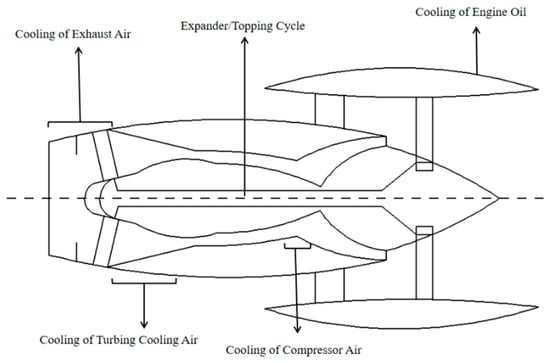
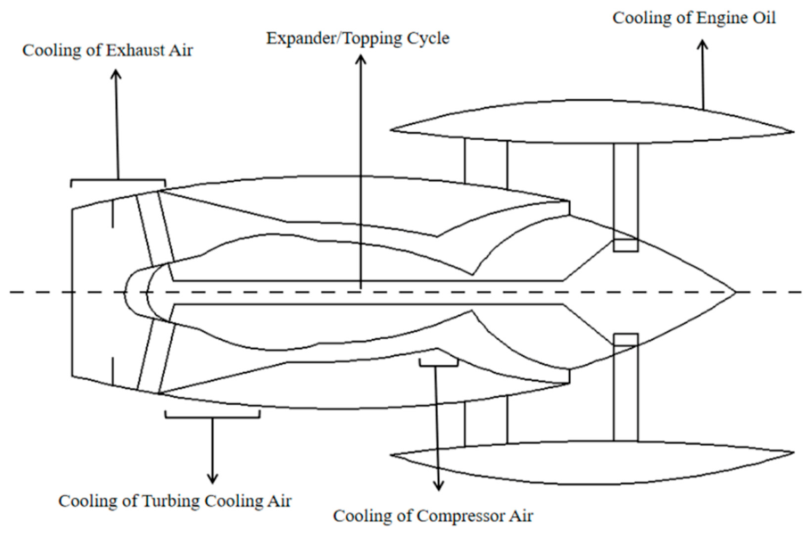
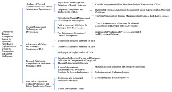
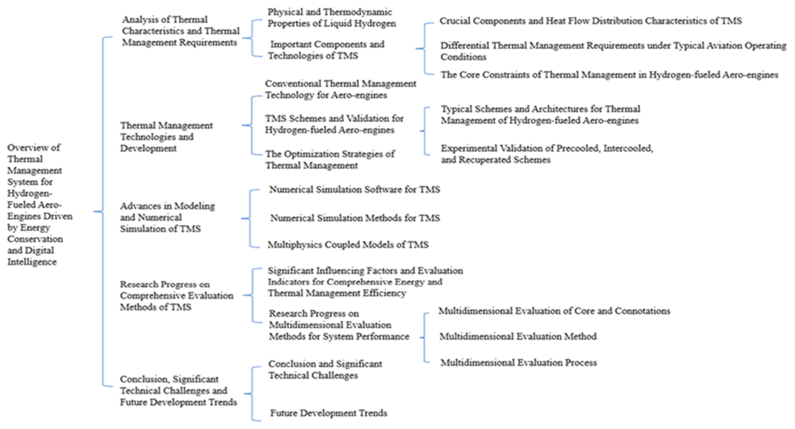
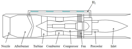
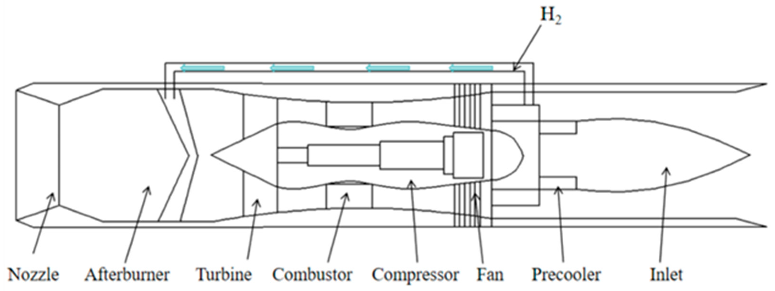
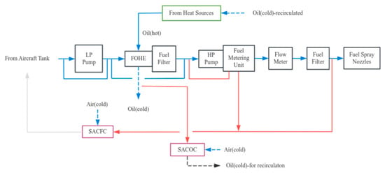
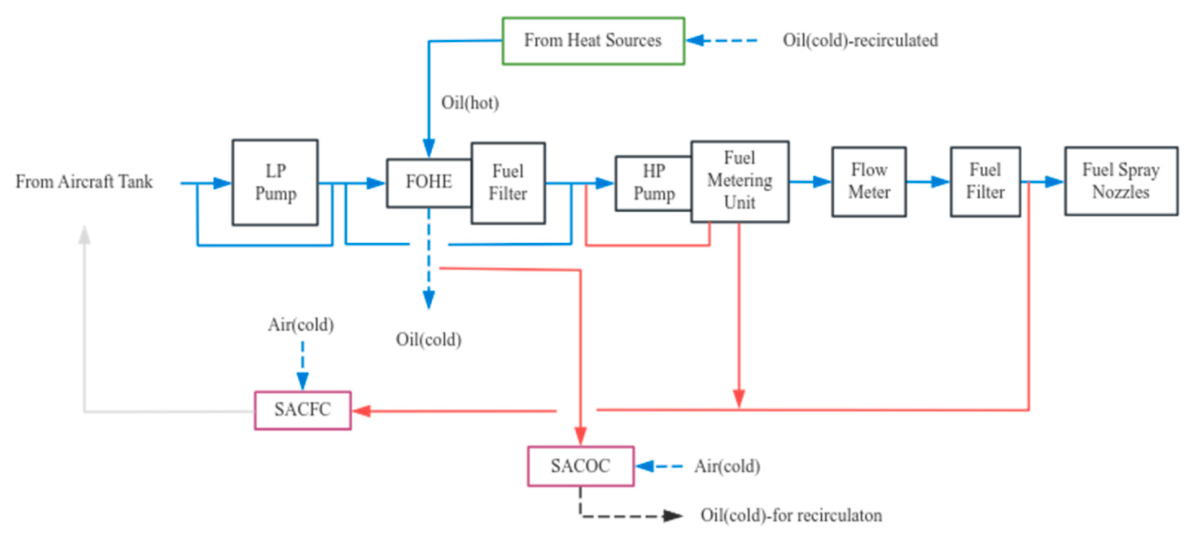
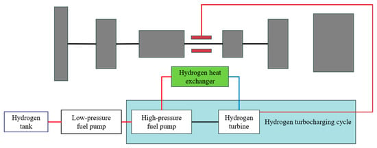
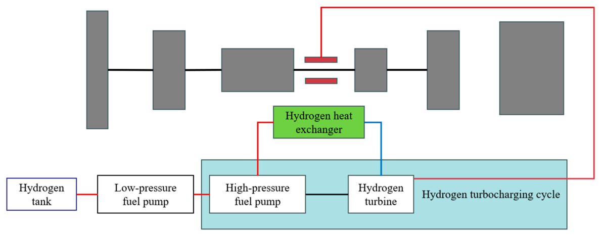
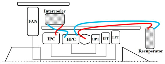
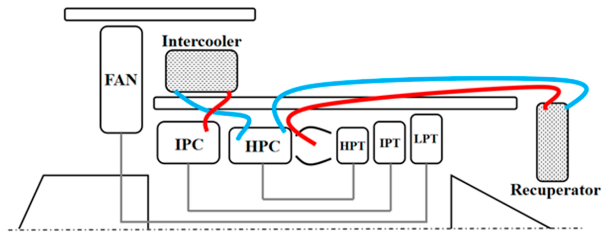
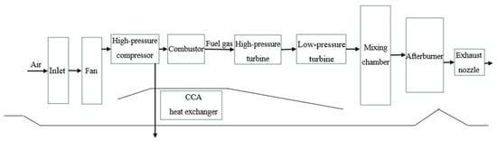
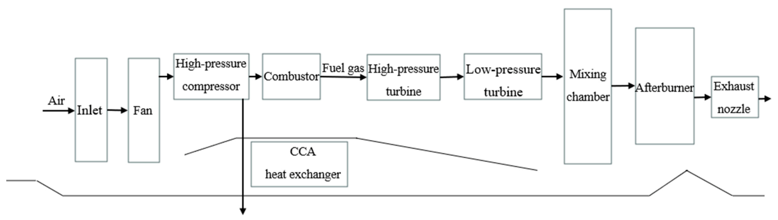
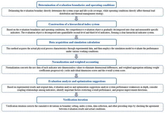
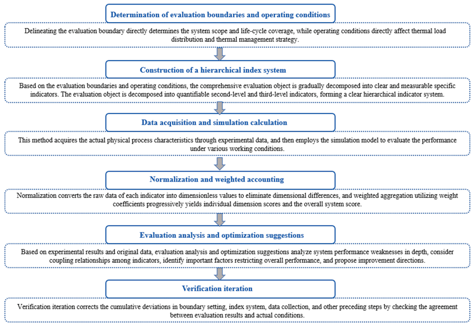

Disclaimer/Publisher’s Note: The statements, opinions and data contained in all publications are solely those of the individual author(s) and contributor(s) and not of MDPI and/or the editor(s). MDPI and/or the editor(s) disclaim responsibility for any injury to people or property resulting from any ideas, methods, instructions or products referred to in the content. |
© 2026 by the authors. Licensee MDPI, Basel, Switzerland. This article is an open access article distributed under the terms and conditions of the Creative Commons Attribution (CC BY) license.