


Abstract
Bone staples that are in fixation of fractures or arthrodesis are mostly fabricated using Nitinol. While the attractiveness of this type of staple is widely recognized, concerns have been raised about the suitability of these staples in patients who are allergic to nickel. In this paper, current studies on bone staples are discussed and have found that existing bone staples are mostly Nitinol-based and are inapplicable to some patients who are allergic to Nitinol. The concept of digital triad (DT-II) is introduced to model, verify and validate bone staples with the consideration of installing parameters in an inserting process. A design study is defined to investigate the impact of two main inserting parameters on clamping forces of a staple. The study leads to the conclusions that with an appropriate adjustment on inserting parameters, new Ni-free β-Ti Alloy can be used to produce bone staples with clamping forces equivalent to those that are made from Nitinol-based materials. These findings may guide orthopedic surgeons in the selection of bone staples for use in a given fracture fixation or arthrodesis case.
1. Bone Staples
Arthrodesis was introduced in 1932 and became popular in early 1950. It was widely used to join a broken bone and assist surgical implants by sustaining compressed bone segments or transmitting inter-segmental compressive force. To fix fractured bones in orthopedic surgeries, screws, pins, plates, rods or staples are widely used to stabilize bone segments in healing processes.
In comparison with other fixation devices, bone staples have good approximation of fragments, dynamic compression, free of pin tract infection, and short operation time. Glasbrenner et al. [1] and Deichsel et al. [2] explored the feasibility of using bone staples or suture anchors to replace interference screws for cortical fixation of tendon grafts in terms of stability. They found that bone staples provided comparable primary stability in cortical fixation, while suture anchors increased elongations with physiological loads.
A bone staple is usually configured with a bridge and two or more legs, and it is used to hold approximated or compressed bone ends statically. Bone staples represent simplicity in design and use. In applications, a bone staple can be simply pounded into a bone to stabilize and heal a fracture. However, bone staples have evolved with new concepts for higher versatility, ease of technical implantation, and better adaptability to a degree of compression in a fracture of osteotomy; this brought some difficulties for surgeons and hospital and operating staff to select, manage, and use new devices appropriately [3,4].
In applications, a bone staple should be customized to regional anatomy, bone quality, expected compression, and the likelihood of post-recovery irritation of patients [5]. Moreover, the healing process may be affected by the applied compression since it helps to increase the size and density of the fracture bone; it is desirable to maintain the clamping force in the entire healing period without discomfort or surgical trauma [6].
1.1. Materials for Bone Staples
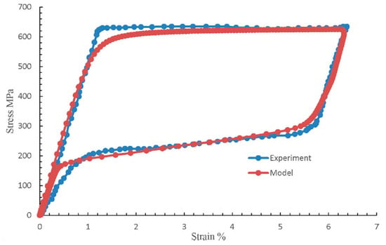
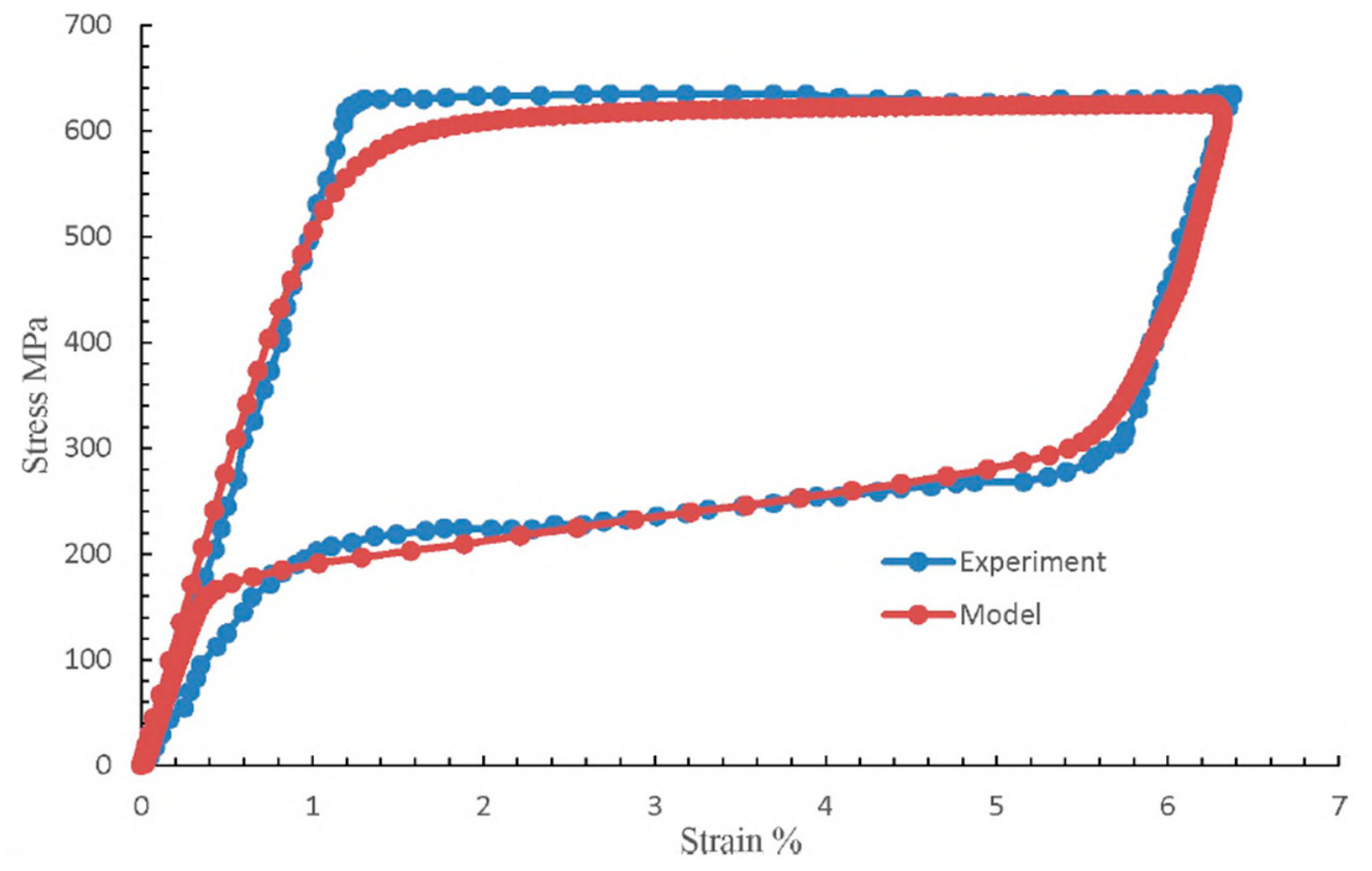
Biomaterials must be biocompatible and sturdy such as titanium and steel. The market size of biomaterials was at the scale of $134 billion in 2017, and the main metallic biomaterials were stainless steel, Cobalt alloys, Nitinol, Titanium, and Titanium alloys [7]. Implant materials for bone staples should meet surgical, biological, fabrication and safety requirements simultaneously. The materials for bone staples can be roughly classified into (1) conventional materials and (2) Nitinol-based shape memory materials. Due of their high biocompatibility and bio functionality, Nitinol and Titanium are the two most used materials for bone staples; moreover, Nitinol is better than Titanium due to its super-elastic properties and shape memory effect. Nitinol bone staples have been widely used in orthopedics since the first commercial introduction in 1980s [8]. Figure 1 shows the super-elastic properties of Nitinol [7].
Figure 1.
Example of super-elastic properties of Nitinol [7].
A Nitinol bone staple can be one of three categories, i.e., super-elastic (SE), body temperature (BT)-activated, and external heat source (HA)-activated. In a super-elastic bone staple, an Austenite finish temperature is less than or close to room temperature, and the staple must be pre-shaped by a tool before it is deployed. The staple attempts to return to its original shape when the temperature is above the Austenite temperature. A BT bone staple has its Austenite temperature below but close to body temperature, it is installed below body temperature, and its elastic deformation will be triggered when it is deployed in a human body. The Austenite temperature of a HA bone staple is slightly above body temperature, and an external heat source is needed to activate elastic recovery.
Al-Takhayneh [9] and Al-Takhayneh et al. [10] discussed the development of new bone implant materials, and they explored the feasibility of prototyping bone staples by 3D printing such as fused deposition modeling (FDM) and stereolithography (SLA). Biocompatible polymers were used to replace conventional metal alloys, and the materials were characterized by tensile tests and thermo-gravimetric analyses. The carbon fiber-reinforced nylon 6 (CF-PA6) was found to be capable of withstanding a force up to 12 kg for an optimized 25% stretchiness, and introducing 20% carbon fiber also avoided a brittle fracture; however, body fluid might affect the integrity of polymers and degrade its properties. Weinstein and Bhakta [5] adopted a low profile titanium alloy to achieve compressive effects of super-elastic Nitinol with comparable mechanical properties of conventional staples. Sanhvi et al. [3] developed a framework to evaluate manufacturability of biomaterials for bone staples, and the evaluation criteria included biocompatibility, mechanical properties, and manufacturability. Gray relational analysis (GRA) and Fuzzy logic were used to evaluate Nitinol, Ti6Al4V, and SS316L, and it proved that Nitinol was the most suitable material for bone staples. Saleeb et al. [6] took into consideration both thermal and mechanical loads in the constitutive model of SMA. User material (UMAT) in Abaqus was used to characterize nonlinear and elastoplastic behaviors of materials such as Titanium [7].
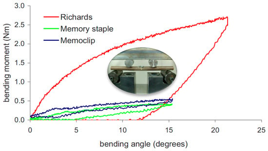
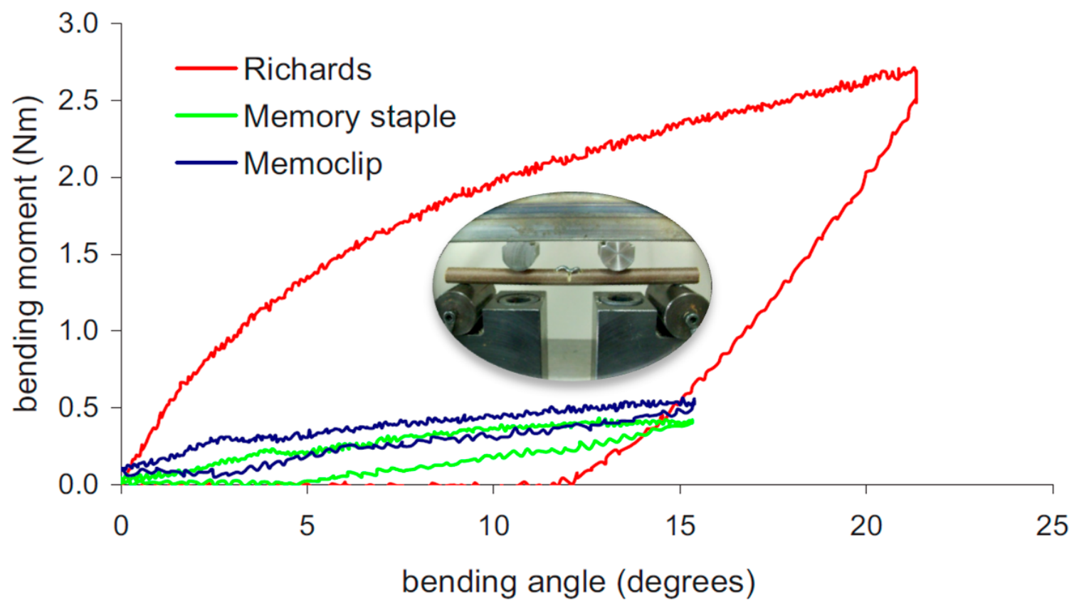
Some new memory staples are available but biomechanical properties are not fully known in comparison with those of standard staples. Rethnam et al. [11] compared a memory staple and HA memoclip with a standard stainless staple by experiment. The standardized bone models were used, and they were made from Tufnol tubes; staples were tested to stabilize models subject to bending or torsional loads. As shown in Figure 2, they found that stainless staples produced a four-times-larger force to resist bending or torsion than two memory staples; however, it was permanently deformed after bending. Two memory staples exhibited similar stiffness and their deformations were elastic.
Figure 2.
Comparison of two memory staples with stainless steel staple [11].
Technavio [12] classified materials for bone staples into two categories, i.e., (1) Nitinol-based shape memory alloys that allow active and continuous bi-cortical compression in the entire healing process and (2) Nitinol alloyed with stainless steel, titanium, vitalism or other metals that provide mechanical compression with high strength instead of by super-elasticity. Nitinol is a primary component in commercial bone staples; Nitinol is an alloy composed of 55% nickel and 45% titanium. It has some unique physical properties that make it an ideal implant material. While Nickel is the primary element of Nitinol, it is a common allergen in patients with contact dermatitis. Around 18% of the population have a nickel allergy that may cause contact dermatitis. In some rare cases, commercial stent grafts could cause systemic allergic reactions to Nitinol. Allergic reaction to Nitinol has been a challenge in medical diagnosis and treatment [13,14]. Despite successful applications of NiTi alloys in minimally invasive medical devices due to its super-elastic properties, not all patients can fully benefit due to the concerns of allergic reactions to Nitinol. Cai et al. [15] discovered a Ni-free β-Ti alloy that possessed comparable strengths of NiTi and allowed a recoverable strain of 5.3% at a deflection ratio of 6%. This study explores the feasibility of using the Ni-free β-Ti alloy in a bone staple for equivalent functionalities of NiTi bone staples.
1.2. Applications
In the USA, around 6.3 million fractures occur annually and 1.5 million fractures are caused by bone disease. In Europe, the number of bone fractures was expected to be increased from 2.7 million in 2017 to 3.3 million in 2030 at an Annual Growth Rate (AGR) of 23% [16]. For parts of fractures that require surgical treatment, orthopedic implants are the most widely used to stabilize fractured bones and promote healing. Globally, the market size of bone staples was estimated to grow at an AGR of 7.22% from 2023 to 2028, i.e., $76.17 million annually. The global market was shared by 19 main companies including Arthrex, Johnson and Johnson, BioPro, Stryker and Zimmer Biomet [17].
1.3. Designs
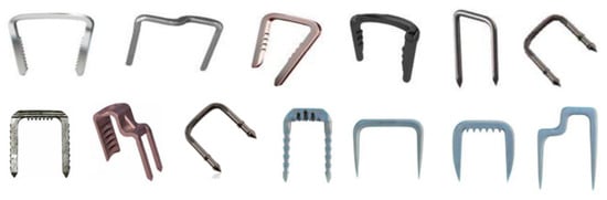
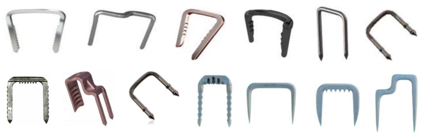
It is desirable to customize a fixation device and the corresponding installation process based on the severity of a bone fracture and required compression forces. As shown in Figure 3, bone staples are different from each other in terms of geometries, cross-section areas, tip-contours, back/base shapes, thicknesses, and, certainly, used materials, as discussed in Section 1.1 [6].
Figure 3.
Exemplifying variants of bone staples [6].
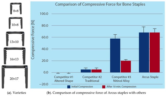
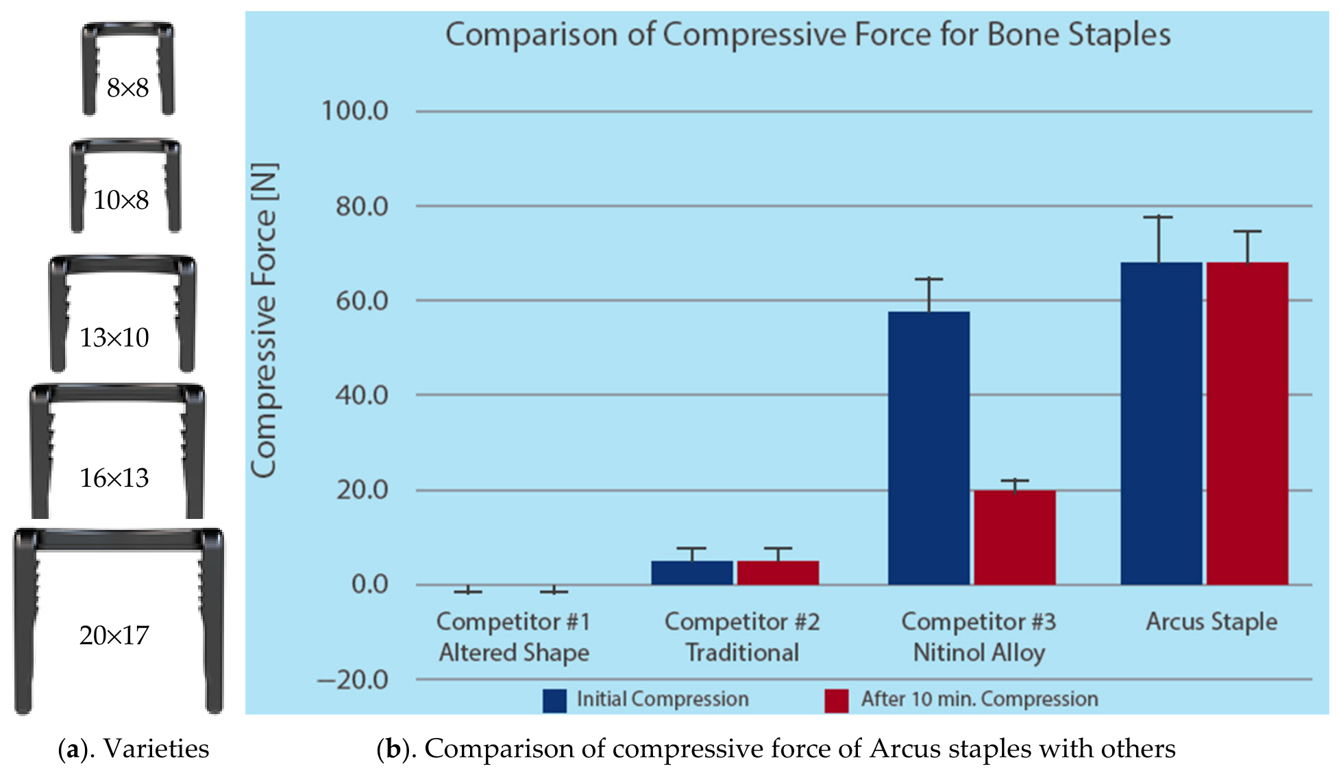
There are no universal bone staples that can be widely applied to different treatments. Manufacturing companies make continuous efforts in proliferating the categories of bone staples and customizing products to individual users. Taking the example of bone staples in Figure 4, Zimmer Biomet [17] adopted an arc design to enhance proximal-to-distal compression; this innovation aimed to retain a compression force for over 600 loading/unloading cycles. A compression force by a Zimmer bone staple could be in a range of (60 N, 80 N), and this improved the load-bearing capability in a range of (20 N, 58 N).
Figure 4.
Arcus staple systems [8,17].
It would be ideal to design a bone staple based on the required force of the bone to be joined in its use. Milgrom et al. [18,19] proposed a solution to measure the strains of a bone when it was engaged in the subject’s motion. Strain-gauged bone staples were used to measure compressions in a bone when the subject was involved in different activities.
Scaphoid is the most easily fractured carpal bone; scaphoid fracture is thus a primary topic to investigate fracture fixation of small bones. Majd et al. [20] compared two different bridge configurations on nickel–titanium (NiTi) bone staples with the same size in scaphoid fracture fixation. Abaqus was used to analyze the distributions of stress and displacement, and they found that the maximum stress occurred in the leg tips of the staple with a straight bridge. The stress concentration of a staple with an s-shaped bridge was highly localized, and maximum stress was eight-times higher than the staple with a straight bridge. Neither of the staples was able to provide ideal healing conditions for fractured bones. Lekston et al. [21] designed a BT and a super-elastic staple for joining the fractures of mandible and face bones. NiTi and TiNico were used as raw materials; the staples were shaped by hot and cold processing to obtain the required diameters. The staples were characterized by measuring shape memory effects based on ASTM F2082-06 standards [22] and measuring super-elasticity in three-bending tests. The superplastic properties of these staples were proven to be applicable to osteosynthesis of bone fractures. Currenton et al. [13] argued that fixation stability was the most critical factor after fusion or fracture surgeries in bone healing. They investigated the impact of bridge geometries on the mechanical properties of bone staples when they were applied in normal and osteopenia bone models. Both shape memory and super-elastic nitinol materials were considered to predict initial and post-surgery compression forces, and maximum principal stresses and stresses on the staples with a 15 mm or 20 mm bridge.
1.4. Simulation
Patients may be sensitive to attached medical devices. It is highly desirable to simulate a surgical procedure to predict surgical outcomes before an actual surgery takes place. In particular, the prediction of anticipated compression and its variation over time helps to estimate viable activation conditions [6]. Salameh [7] used the finite element method to analyze and compare contact forces by two bone staples that were made from Nitinol shape memory alloy and Titanium alloy, respectively. The bone staple using Nitinol was found to produce a high compression force mainly due to its rate-dependent inverse relaxation properties. The predicted forces were validated by experiments. Frydrýšek et al. [23] simulated a staple that was made of stainless steel; it was applied on a tibia model with two layers to represent corticalis and spongiosis, respectively. They expected to use simulation data to evaluate the safety and applicability of bone staples for bone growth arrest. To assess bone staples’ capabilities for appropriate deformations in orthopedic surgery, Halo et al. [24] used FEA to investigate the impact of design variables on stress and strain distributions. Recently, Dundar et al. [25] conducted a comparative study of titanium fixation plates and NiTi staples; Jia et al. [26] investigated mechanical performance of compressive bone staples made from NiTi and Ti-Zr-Nb-Sn alloy by finite element analysis.
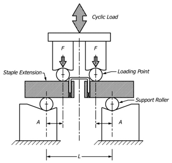
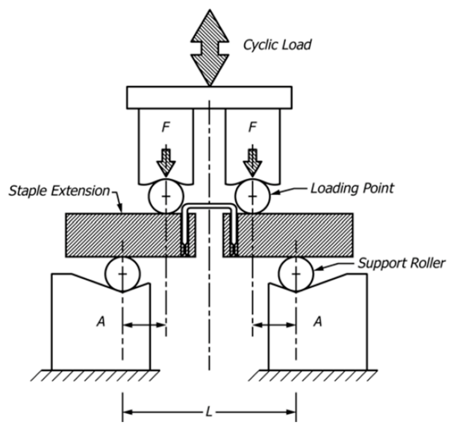
Even though Nitinol staples are widely used in orthopedic treatment, their mechanical properties are not fully known in comparison with the properties of other materials such as stainless steel or Titanium. Dall’Omo [16] used FEA to evaluate biomechanical properties of fixation implants subject to different loading conditions. A framework was established to support the development and tests of medical devices. The simulation models were established based on ASTM F564-17 standards for elastic bending tests and fatigue bending tests as shown in Figure 5. ASTM F564-17 represents standard specification and test methods for metallic bone staples. It covers the characterization of the designs and mechanical properties of metallic staples in internal fixations of musculoskeletal systems.
Figure 5.
ASTMF564-17 bending tests [16,27].
1.5. Installation
A Nitinol bone staple is chilled, opened, and then inserted in a set of predrilled holes. Once it is placed appropriately, it tends to recover its original shape, and this induces a compression force on fractured bone. Accordingly, the installation involves four steps: (1) set up and align two broken pieces of the bone in the desired positions; (2) find the right positions and orientations and drill holes to hold a bone staple; (3) insert the staple into the hole and press it firmly until the staple is fully inserted; (4) post-process the bone when it is needed to trigger elastic recovery [8,16]. A few studies discussed some issues related to the removal of bone staples after fixation treatment. Gillquist [28] conducted a study to measure the forces required to remove a staple from bone cement and from calf bone in predrilled holes. It was found that an average maximum force of 500 N was required to remove a staple. When the serrations of the legs were reduced by 75%, the staple was impossible to remove. Therefore, special care should be taken to avoid the complication with staple removal.
Bone staples can be characterized by experiments, simulations or both. Ferrara et al. [29] measured sustaining compression forces in simulated fractures by the Arcus® Staples; the forces in both static holding condition and the cyclical dynamic bending condition were measured. The results demonstrate satisfactory performance of their products in stabilizing fractured bones. Russell et al. [30] characterized biomechanical properties of new SMA in different configurations of bone staples by testing. Mechanical tests included dorsal four-point bending, medial four-point bending, dorsal three-point bending, and plantar cantilever bending at 37 °C, and the measurements included max loads, stiffness, and plantar gripping. The tests found that Nitinol bone staples exhibited improved rigidity and compression forces for lapidus arthrodesis.
Carbonaro et al. [31] combined numerical simulation and experimental methods to characterize super-elastic bone staples with two and four legs, respectively. Four-point bending tests were performed to measure the compression forces, and finite element analysis was conducted to understand super-elastic behaviors of Nitinol bone staples. Their works concluded that material properties of Nitinol materials affected the mechanical behaviors of bone staples significantly, and there was the need to characterize the materials and staple geometries separately. Saleeb et al. [6] simulated the key stages of bone stapling in a shape memory alloy (SME) osteosynthesis. SME materials were nickel-rich NiTi and processed by powder metallurgy (PM), and it was characterized as a three-dimensional constitutive model. The simulations on a body-temperature-activated bone staple took into consideration the thermo-mechanical loading conditions. The experiments validated the simulation results that the staple was able to produce an adequate compressive force and provide a stable clamping force to assist the coaptation of a fractured bone.
2. Modeling of Bone Staples
The validity of the simulation results relies on (1) the comprehensiveness of a model that represents used biocompatible materials and (2) the abilities of the simulation tool to model nonlinearities of materials, contacts, and dynamic loads. There are a number of challenges in modeling and simulating a bone staple, including (1) defining the contacts of a bone staple with bone tissues, (2) defining combined mechanical and thermal loading conditions, and (3) determining the main variables that reflect main factors of an installing process adequately.
In this project, the client is especially interested in evaluating if Ni-free β-Ti alloy can be used to replace a type of SE conventional TiNi in bone staples to achieve an equivalent compression force within its range of recoverable strains. Note that the details of mechanical characterization of Ni-free-β-Ti alloy were provided in the literature [15]. Since a SE bone staple must be preloaded in the installation process, it is critical to understand how the bone staple is deformed by using a certain installation kit. The stress and strain distribution, in particular, the location of maximized strain or stress can be affected by the design of an installation kit, and this affects the compression force in the deployment of the bone staple greatly.
To our knowledge, no work has been reported on the impact of the design of an installation kit on stress and strain distribution as well as compression force in the deployment of a bone staple. In the following, a numerical simulation is conducted to investigate the impact of installation variables on the performance of a bone staple.
2.1. Digital Triads (DT-II)
Modern products have evolved and upgraded in ever-shortening development cycles due to emerging new materials, processes, technologies, and markets’ needs. Digital technologies have been playing more and more important roles in accelerating products’ development processes by (1) modeling and simulating products’ behaviors, (2) analyzing, comparing, and optimizing design alternatives against expected requirements, and (3) performing verification and validation (V&V) in the digital world to minimize iteration in engineering design. For example, Balta et al. [32] developed a cyber–physical system framework to support data-enabled decision-making mechanisms. Lesi et al. [33] suggested collecting data from internet of things (IoT) and utilizing data to enhance the controls of discrete event dynamic systems. Proia et al. [34] discussed some critical needs in supporting sensor-based human–robot-collaborations. Conti et al. [35] integrated commonsense knowledge reasoning to enable human and machine collaboration.
A product is defined for its uses with specific functions; therefore, the purpose of the product can be defined as a set of Functional Requirements (FRs). However, one set of given FRs may be satisfied by many different designs. To optimize manufacturing businesses, various products’ designs that have the potential to satisfy all FRs should be analyzed, assessed, and compared to select the best one in terms of functionalities, costs, and environmental friendliness. When products are complex, highly diversified, or applications involve various changes, it makes it a significant challenge to define FRs and design constraints of products explicitly. Therefore, it becomes most critical to verify and validate a design solution thoroughly in the virtual world before it is fabricated and used in the physical world. A thorough V&V minimizes the waste caused by design errors or omissions in an iterative design process.
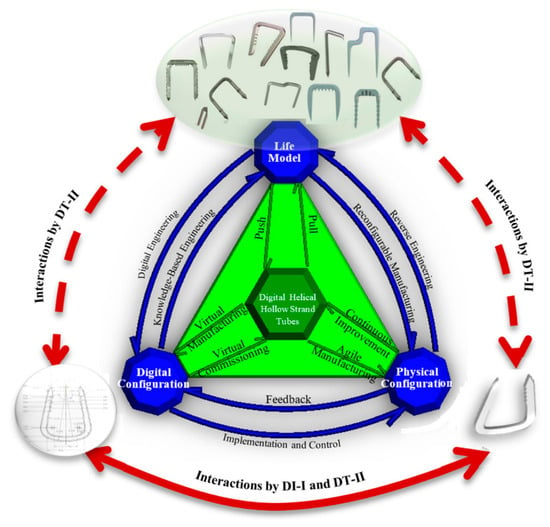
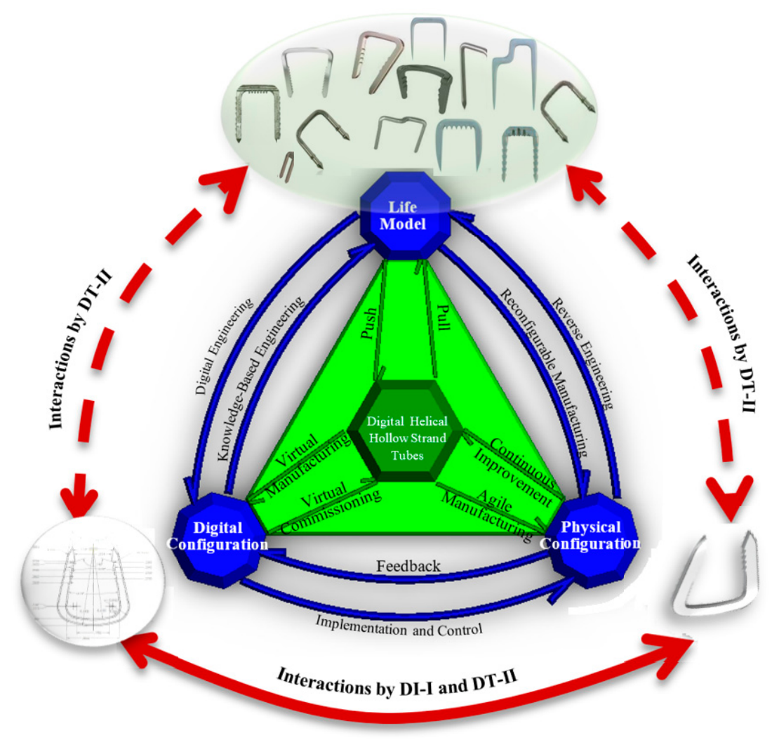
As shown in Figure 6, the concepts of Digital Twins (DT-I) or its extended Digital Triads (DT-II) can be developed to meet the needs of virtual V&V (VVV) thoroughly. V&V activities are performed virtually to a great extent to pursue sustainable products by minimizing non-value-added physical experiments and tests. DT-I and DT-II can be used to implement the First Time Right (FTR) transformation from a digital twin to its physical twin [36]. Note that a digital twin of a physical thing refers to a virtual model in computers for the representation of (1) system properties, characteristics, and behaviors in response to external changes, (2) the interactions with relevant objects in applications. On the one hand, a number of virtual models can be developed for the same physical mode. On the other hand, numerous virtual models are available to meet the same set of given FRs. Enabling technologies such as Computer Aided Engineering (CAE) are used to analyze, evaluate, and compare these virtual models and finally select the best virtual solution before it is transformed into its physical solution in the first-time right practice.
Figure 6.
Digital Twins (DT-I) and Digital Triads (D-II) for designs of sustainable medical products [37,38].
2.2. Bone Staples in Case Study
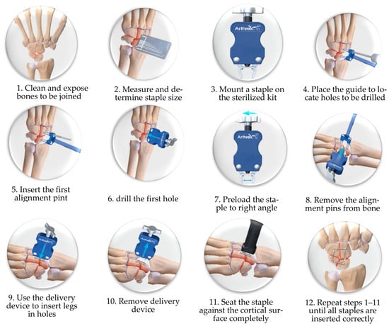
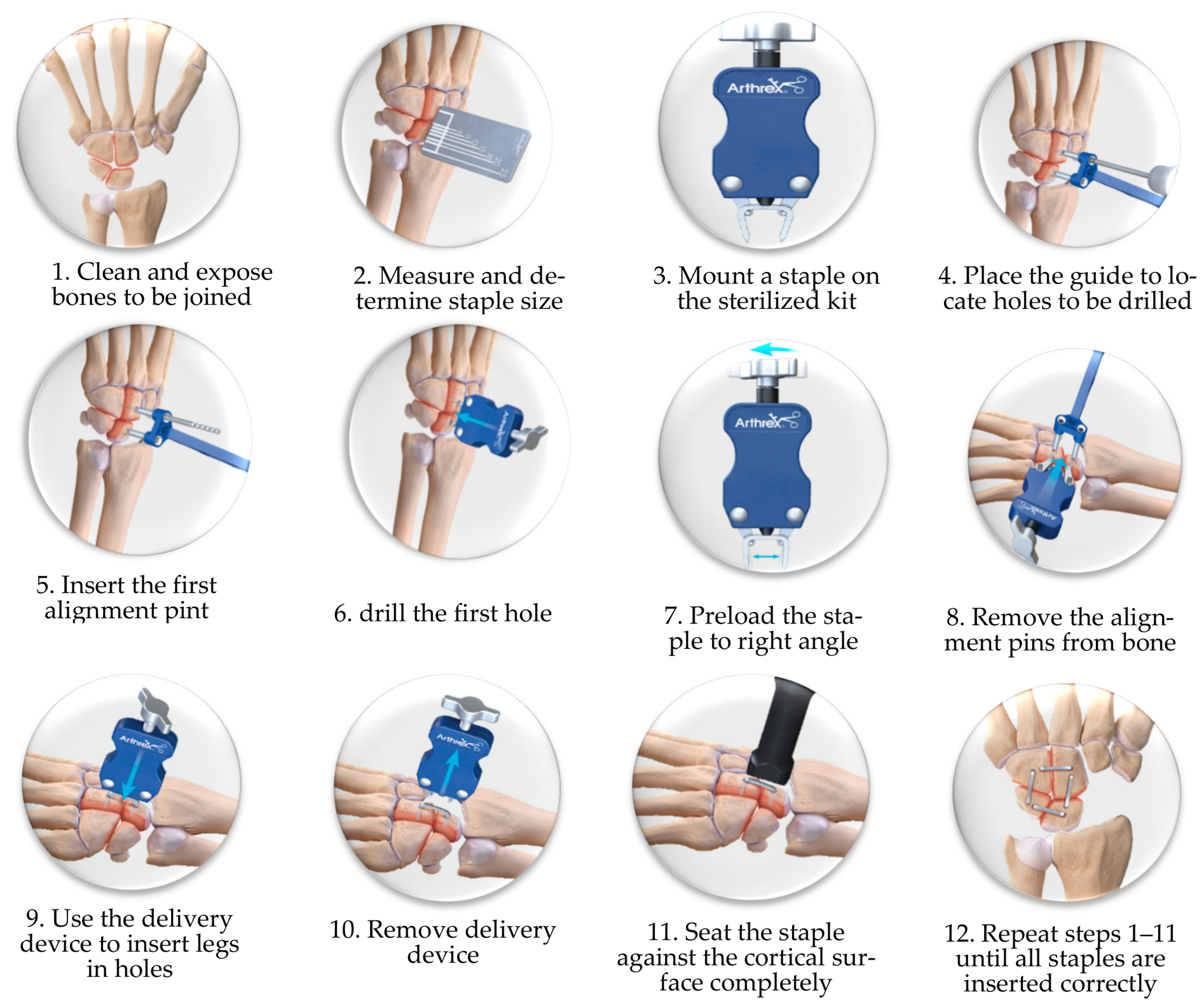
A DynaNite Nitinol staple (Arthrex, Inc., Naples, FL, USA) was chosen as a benchmark product to explore the feasibility of using substitutive materials for equivalent functions. A Dynanite Nitinol staple offers low-profile compressive fixation and can be deployed easily by following the detailed steps shown in Figure 7 [39]. Other commercial bone staples, such as EasyClip® by Stryker [40] and DePuy Synthes [41], follow similar steps for installations on a fractured bone.
Figure 7.
Steps in installing a bone staple [39].
2.3. Parametric Modeling
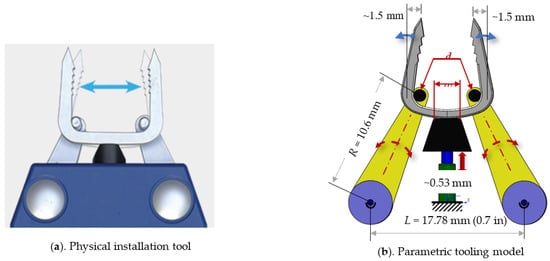
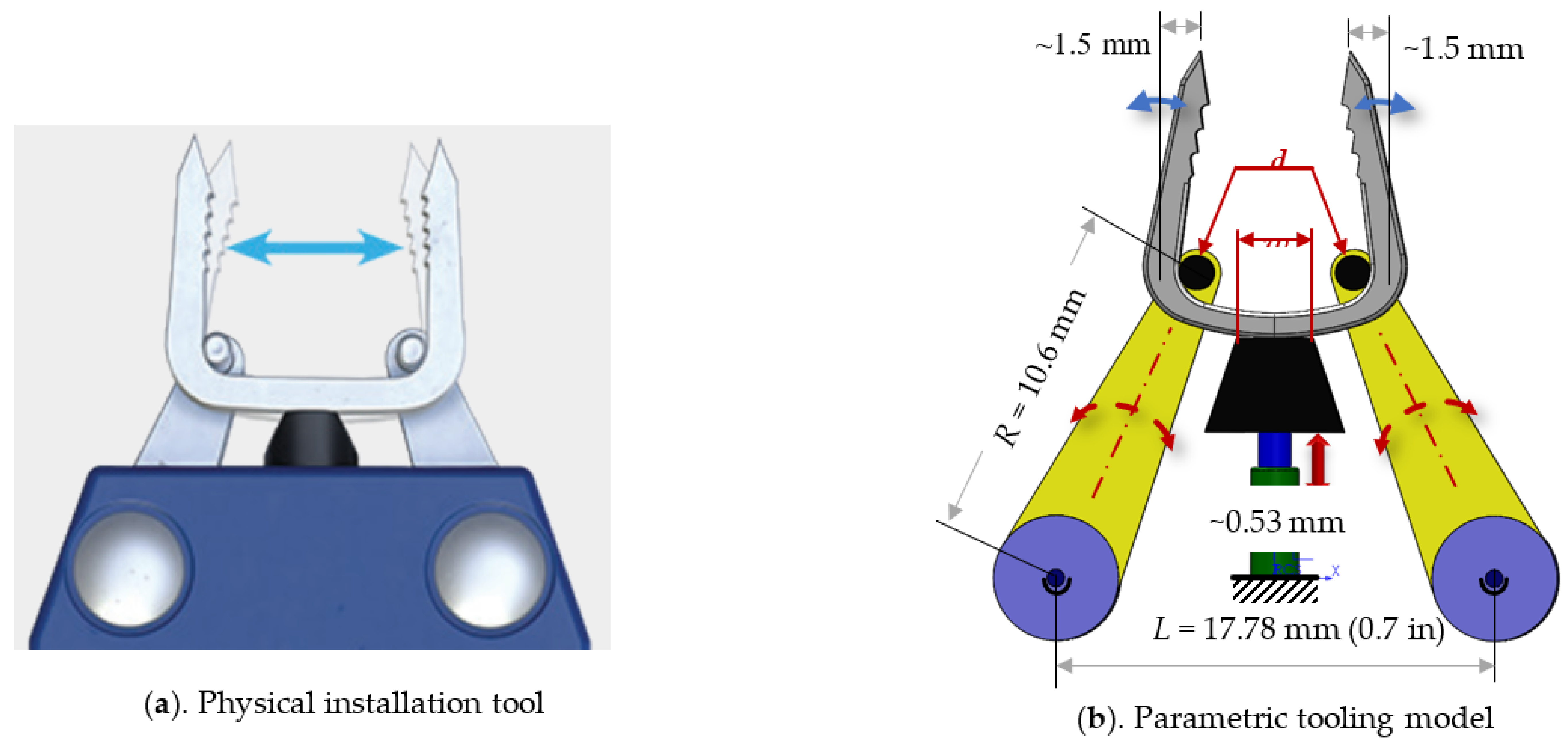
It is critical to understand how a bone staple is preloaded in installation so as to determine the compression force in its deployment. Taking a reference of the commercial product by Arthrex [39], a parametric model is created for the installation kit as shown in Figure 8. A bone staple is initially inserted and supported by (1) two pins on each side and (2) a flat plate in the middle. The bone staple will be installed by turning a screw on the tool, and this adjusts the height of the contact point between the flat plate and the bottom of the bone staple. A full preload of the bone staple corresponds to 0.53 mm from the bottom of the staple. The bone staple is completely loaded by its contacts with two pins and the flat plate when the branch on either side is expanded around 1.5 mm to its vertical position. It is our understanding that the support of two pins and the landing length of the flat plate will affect the distributions of stress and strain over the bone staple, and thus further affect the compression force in the deployment of a bone staple.
Figure 8.
Parametrical model of installation kit for bone staples.
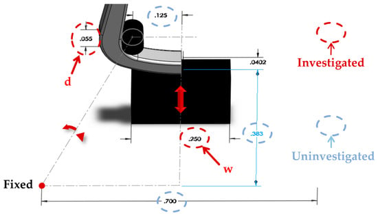
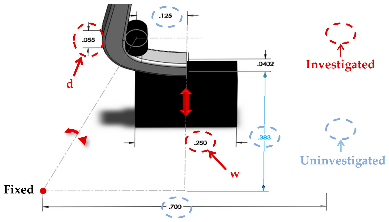
Figure 8 shows that the installation setup can be modeled by four parameters, i.e., ‘w’ for the width of the flat landing area; ‘d’ for the diameter of a pin; ‘L’ for the distance of two supports of pins; ‘R’ for the distance from the center of a pin to its support. To illustrate the capabilities of numerical simulation, this research chooses ‘w’ and ‘d’ to investigate the impact of installing parameters on stress and strain distributions of bone staples.
2.4. Material Properties
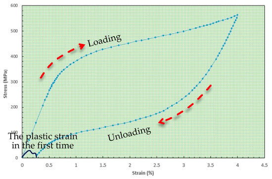
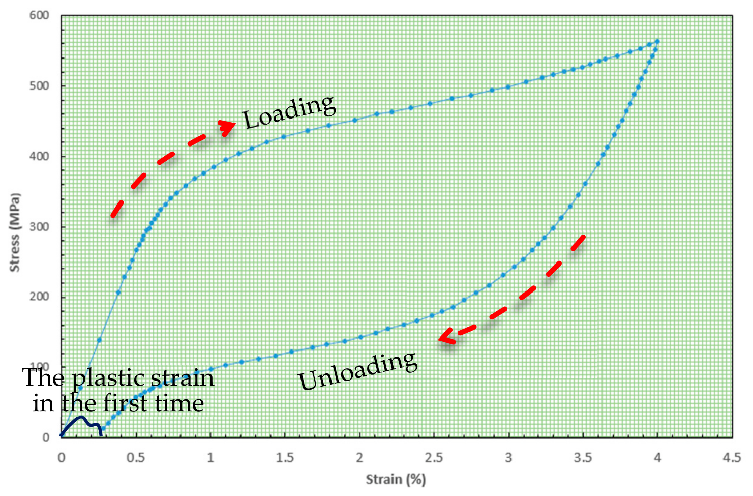
Figure 9 shows a typical stress–strain curve of the Ni-free β-Ti alloy. The curve consists of two segments for the materials’ responses in a loading and unloading process, respectively. The upper part of the curve in the loading process begins with an elastic deformation when the stress is below 300 MPa, and it becomes highly nonlinear when the stress exceeds 300 MPa. The lower part of the curve in the unloading process shows a varying elastic modulus depending on the stress level and historical loadings. The material properties are highly nonlinear.
Figure 9.
Stress–strain curve of Ni-free β-Ti alloy.
Some finite element simulation packages such as Abaqus are able to define nonlinear materials with super-elastic (SE) properties by creating user material subroutines [42,43]. A material with SE properties can be parametrized with eight coefficients that are obtained and calibrated experimentally. However, it assumes that the alternating load has the same amplitude. In fact, this is not true since some materials such as Ni-free β-Ti alloy produce different stress–strain curves when the maximized stress in one loading cycle is different from that in another.
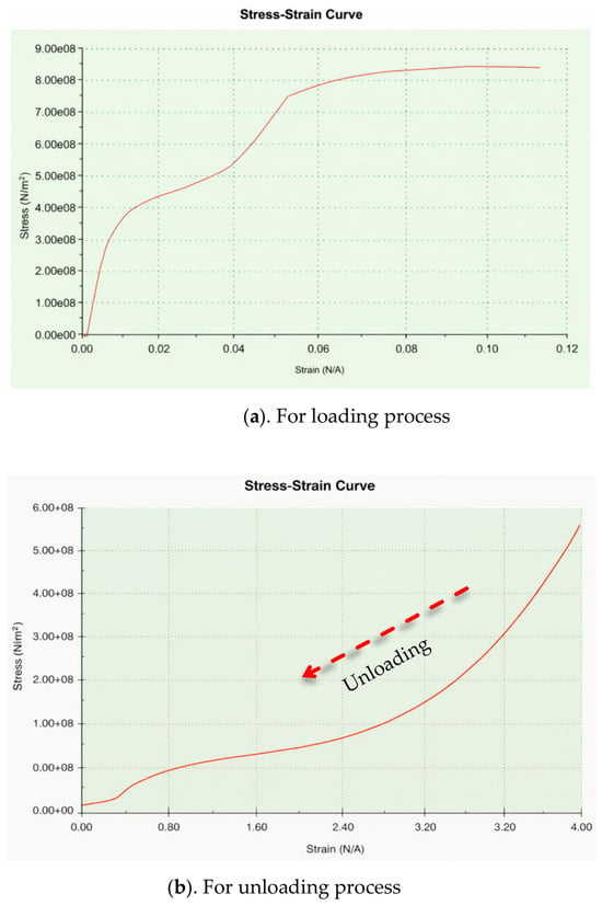
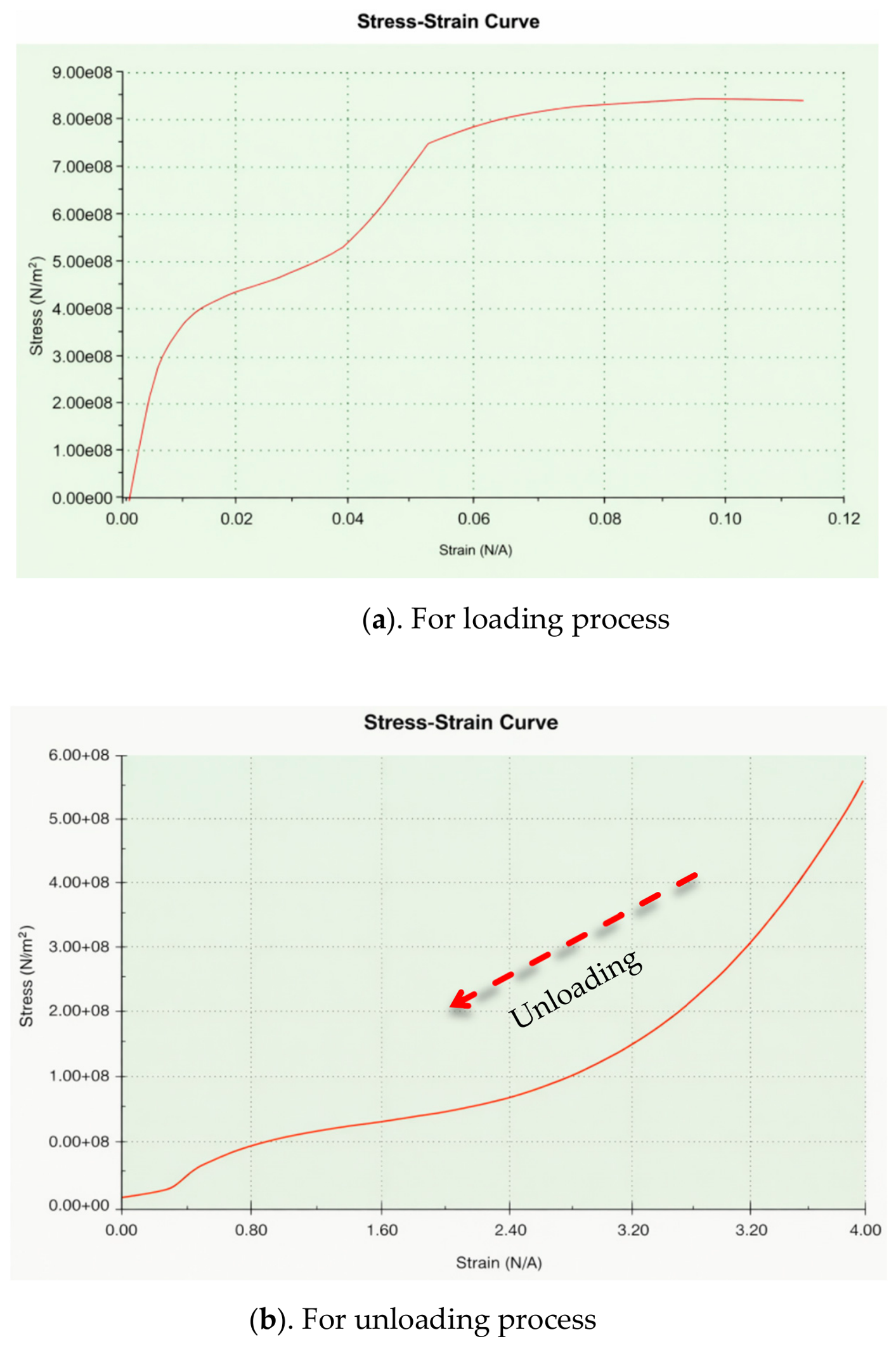
The ‘Nonlinear Analysis’ in 2025 SolidWorks Simulation is utilized in this project. This package does not allow us to define SE properties by using user material subroutines directly. To take into consideration nonlinearity and the difference responses of materials in the loading and unloading processes, we divide the stress–strain curve into two segments, and they are used to define nonlinear material models in the loading and unloading processes (see Figure 10), respectively.
Figure 10.
Nonlinear materials models in loading/unloading processes.
2.5. Nonlinear FEA Model
A nonlinear analysis is desirable to analyze nonlinear relations of applied forces and displacements. Nonlinear relations can be caused by geometrical changes (i.e., large deformations or large strains), material properties (i.e., super-elastic or elasto-plastic), contacts, or dynamic loads. All these effects will result in changes in stiffness matrices and loading vectors. To solve a nonlinear model, the time domain should also be discretized to solve a series of solutions in discretized times based on initial conditions step by step [44].
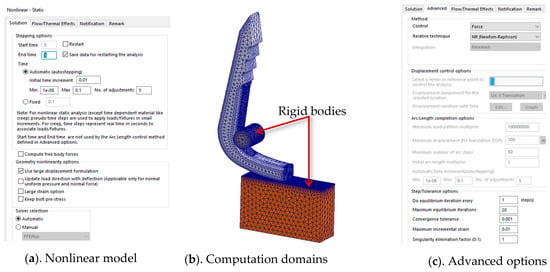
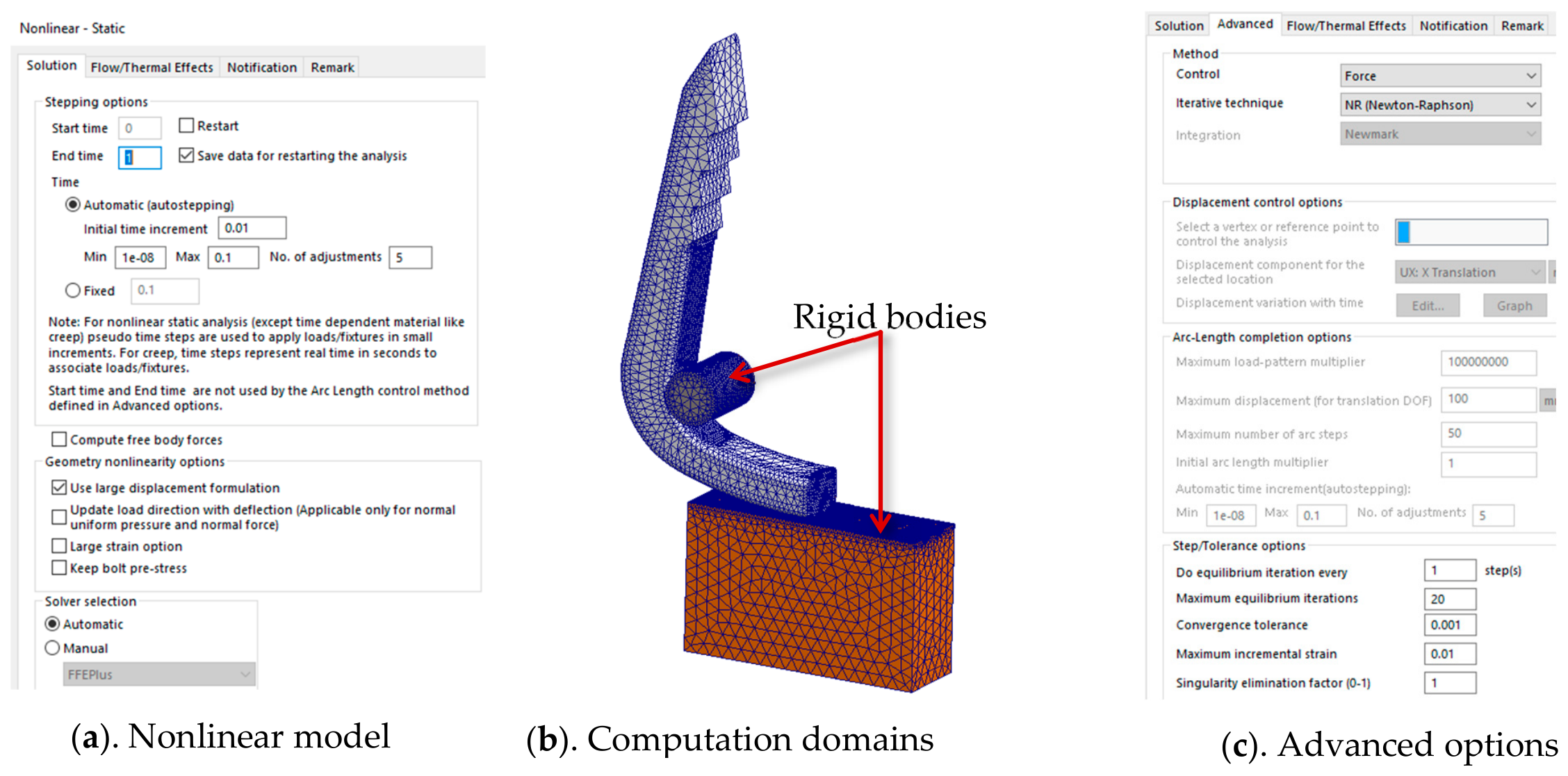
Figure 11 shows the definition of a nonlinear model for a bone staple. The loading is applied on a bone staple slowly; therefore, the impact on velocities or kinematic energy can be ignored and the ‘static’ loading is selected. Moreover, the deformation of the bone staple is focused; the components from the installation kit including the pin and the flat plate are treated as a ‘rigid body’. SolidWorks Simulation allows us to set advanced operations for the resolution in the time domain, the applied control method, iterative technique, and convergence conditions as shown in Figure 11a,c.
Figure 11.
Define a nonlinear FEA model.
2.6. Boundary Conditions
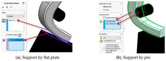
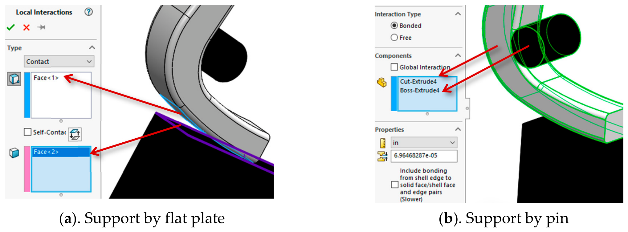
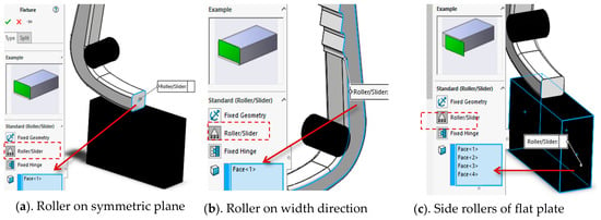
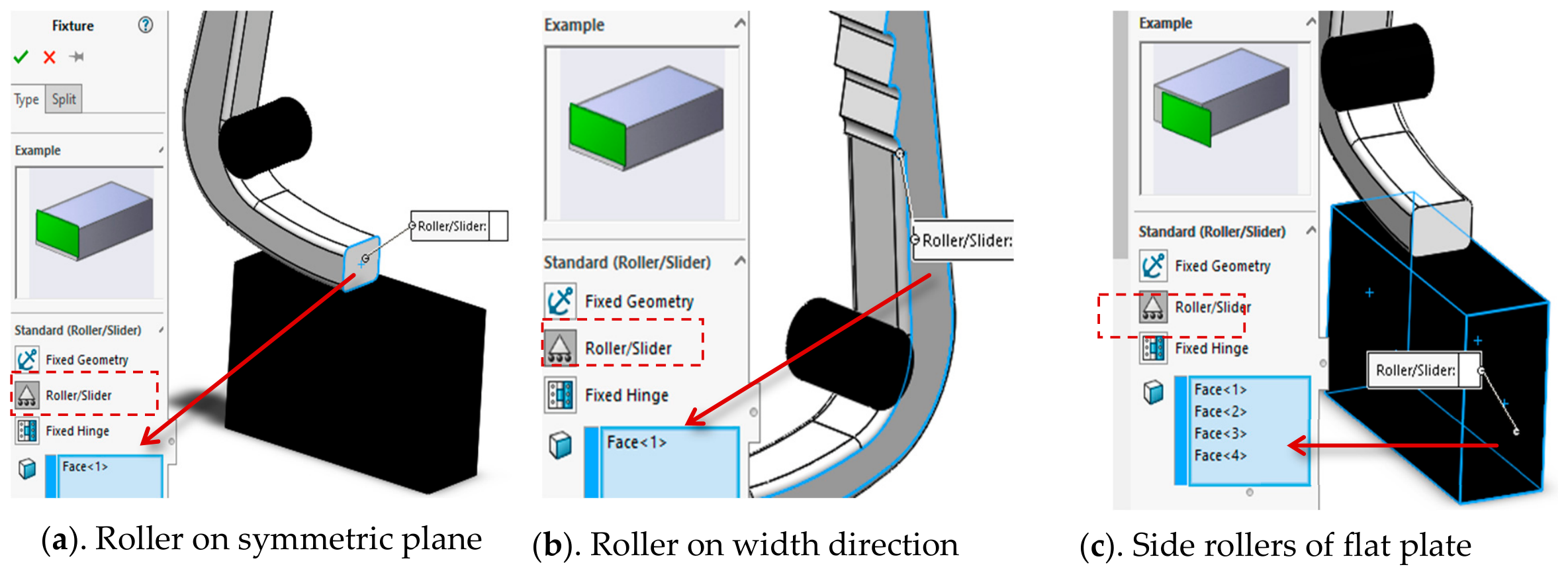
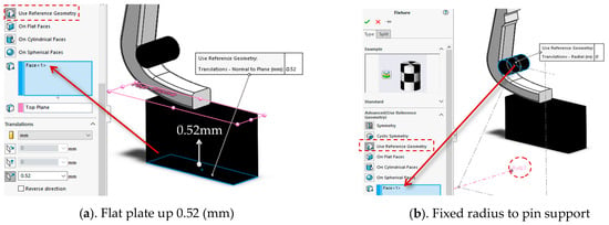
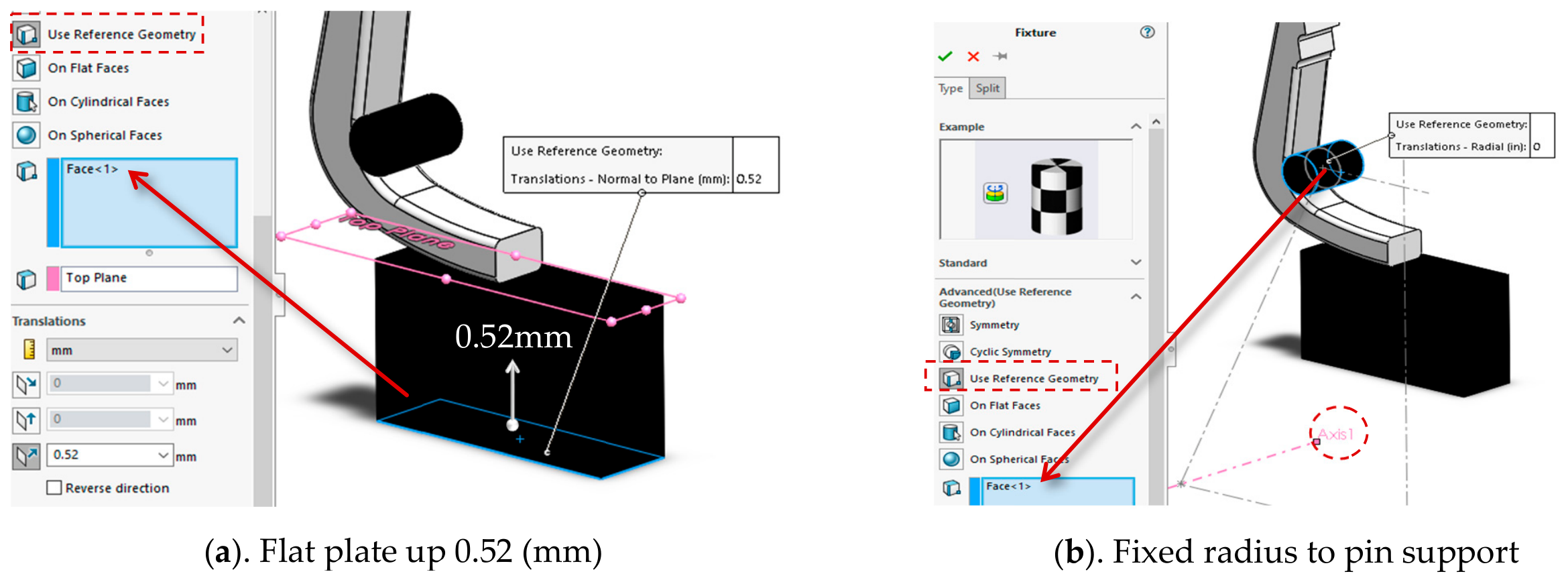
Boundary conditions (BCs) of an assembled FEA model include three components: (1) BC-I: contact surfaces, (2) BC-II: fixed or rolled geometries, and (3) BC-III: external loads including pre-set displacements of geometries. Based on the steps of the installation process, three components of BCs for a bone staple model are defined in Figure 12, Figure 13 and Figure 14, respectively.
Figure 12.
Contact surfaces (BC-I).
Figure 13.
Fixed or rolled geometries (BC-II).
Figure 14.
Pre-fixed geometries (BC-III).
2.7. Stress and Strain Distribution and Clamping Force
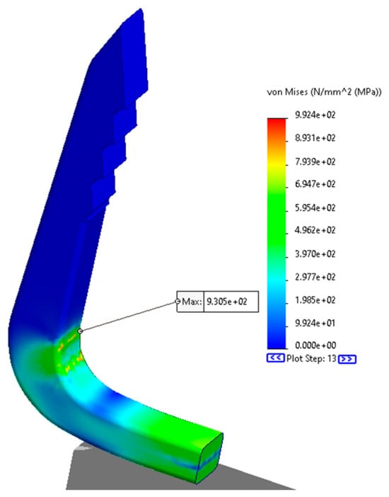
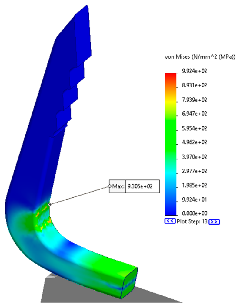
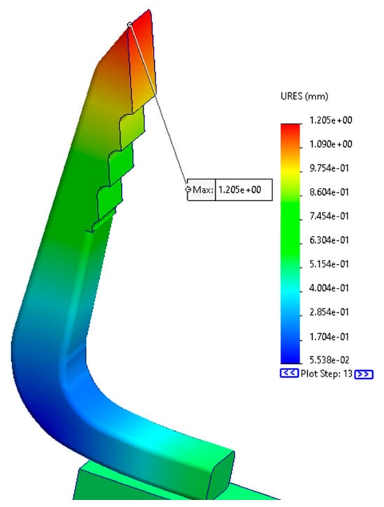
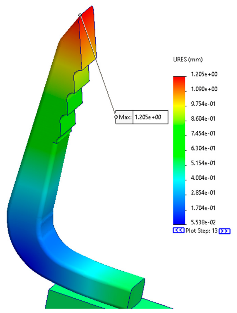
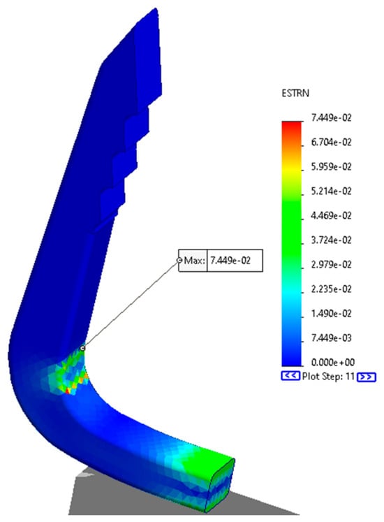
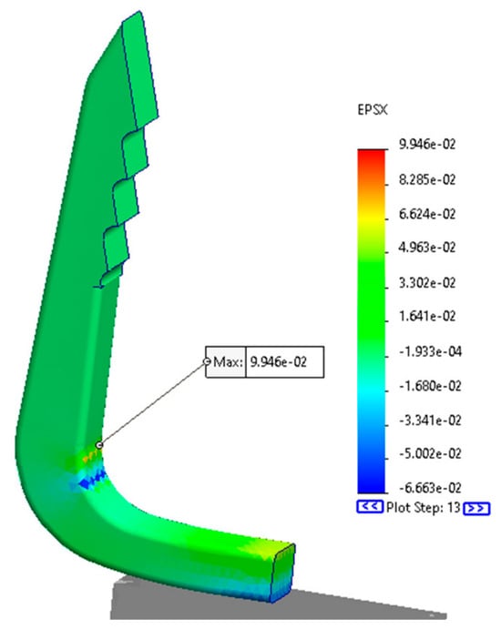
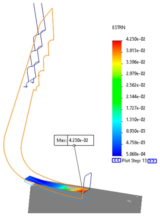
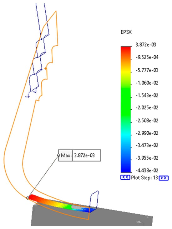
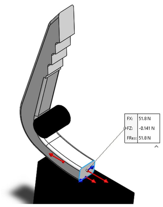
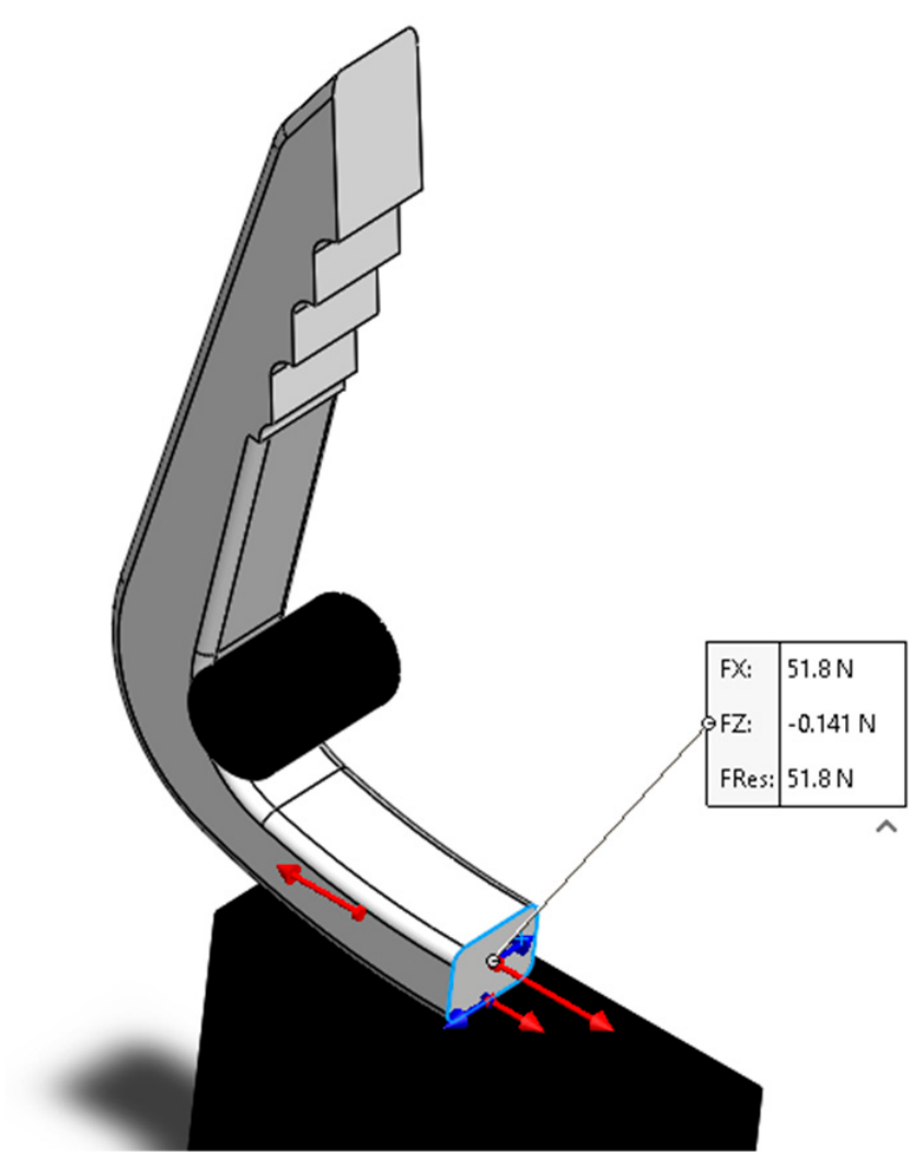
Simulating the bone staple model based on specified BCs in Section 2.6 results in all information relevant to the responses of the bone staple to the preloaded displacement by the installation kit. Figure 15, Figure 16, Figure 17, Figure 18, Figure 19 and Figure 20 show the examples of the locations of maximum stress, displacement, total strain, x-normal strain on the bone staple, the locations of maximum total and x-normal strains at the contact with the flat plate, and the clamping force involved in the symmetric plane of the bone staple, respectively. Figure 15 and Figure 17 show that the max stress and strain occur at the contact surface of the pin with the bone staple at the values of 930.5 MPa and 7.449%, respectively. Figure 21 shows the equilibrant clamping force in preloading is 51.8 N when two legs of the bone staple have a relative opening of 2 × 1.205 = 2.410 (mm) as shown in Figure 16.
Figure 15.
Map of von Mises stress distribution.
Figure 16.
Map of displacement distribution.
Figure 17.
Map of total strain distribution.
Figure 18.
Map of x-normal strain distribution.
Figure 19.
Map of distribution of total strain at contact with the flat plate.
Figure 20.
Map of the distribution of the x-normal strain at contact with the flat plate.
Figure 21.
Clamping force in preloading (N).
3. Parametric Study on Installing Process
The exemplified results in Section 2.7 assume that all of the five installation parameters in Figure 8b are given. For example, the size of two pins (d) is set as d = 0.055 (in) and the width of the flat plate (w) is set as w = 0.25 (in) as shown in Figure 22. Since a bone staple is preloaded by the displacements that force two legs to their upright positions, there are numerous ways to achieve this; different pre-loading approaches may result in different strain and stress distributions over the bone staple, and these affect the expected compression forces in deployments. Since the DT-II allows for the mix of different uniting systems in defined geometric dimensions and field variables, we specify that the unit of w and d is inches for the rest of the discussion.
Figure 22.
The bone staple installation parameters used in FEA.
Table 1 shows the setup of the design study where the width (w) of the flat plate and the diameter of the pin (d) are selected to investigate the impact of an installation process on the stress and strain distribution of the bone staple. The width (w) of the flat plate is in the range of (0.010, 0.250) inches at the step size of 0.020 inches with a total of 13 levels; the diameter (d) of a pin is the range of (0.050, 0.075) inches at the step size of 0.005 inches with a total of 6 levels. There are 78 levels in this design study.
Table 1.
Variables (w and d) in design study.
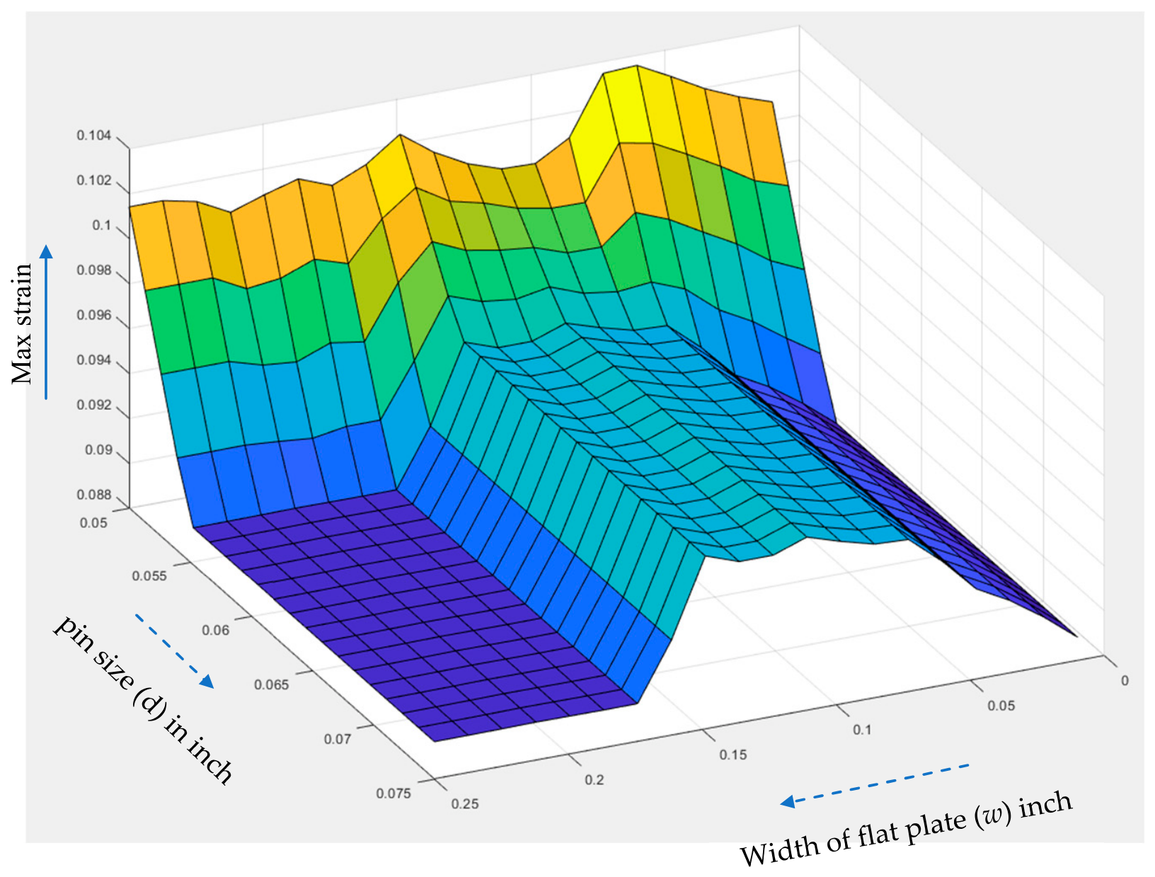
Table 2 shows the outcomes of the design study. With the same BCs to lift the flat plate for a displacement of 0.52 mm and setting the distance of the center of the pin to its support as constant, the maximum strain of the bone staple was minimized with the width (w) of the plate and the diameter (d) of the pin set as 0.010 and 0.060 inches, respectively. Correspondingly, the minimized maximum strain and stress are 0.08903 and 968.7 MPa.
Table 2.
Simulation results of design study.
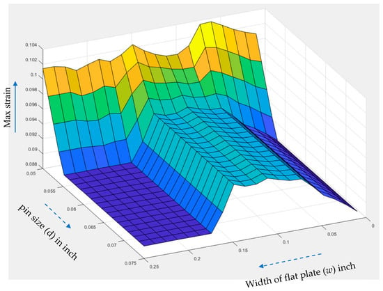
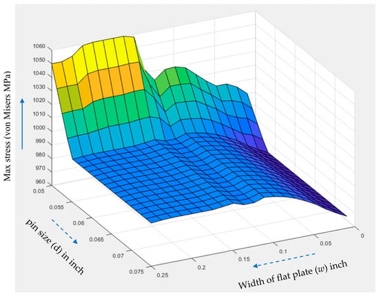
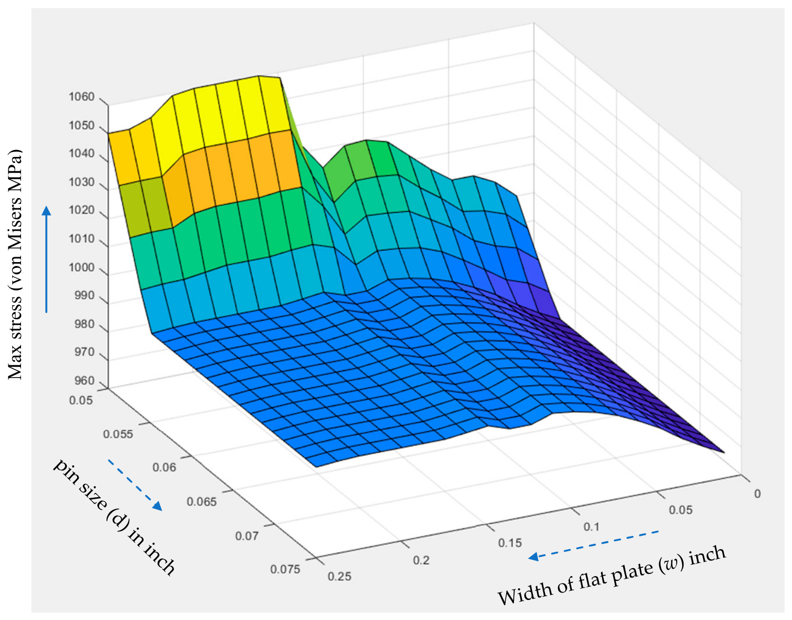
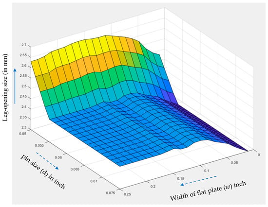
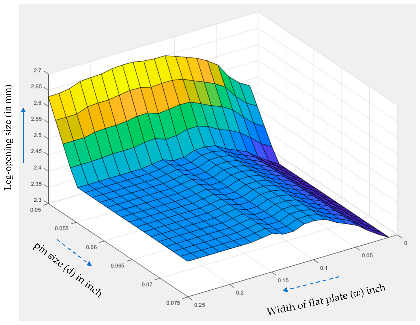
Figure 23, Figure 24, Figure 25 and Figure 26 visualize the results in Table 2. Furthermore, Figure 23 shows that the max strain will be reduced when the width (d) of the flat plate is reduced. This is because the max strain occurs at the contact of the pin and bone staple. The narrower the flat plate, the less the bending moment applies on that contact.
Figure 23.
Max strain of bone staple versus the size changes in pin and flat plate.
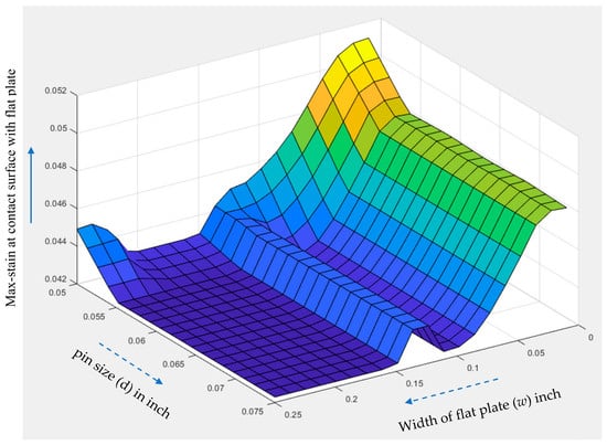
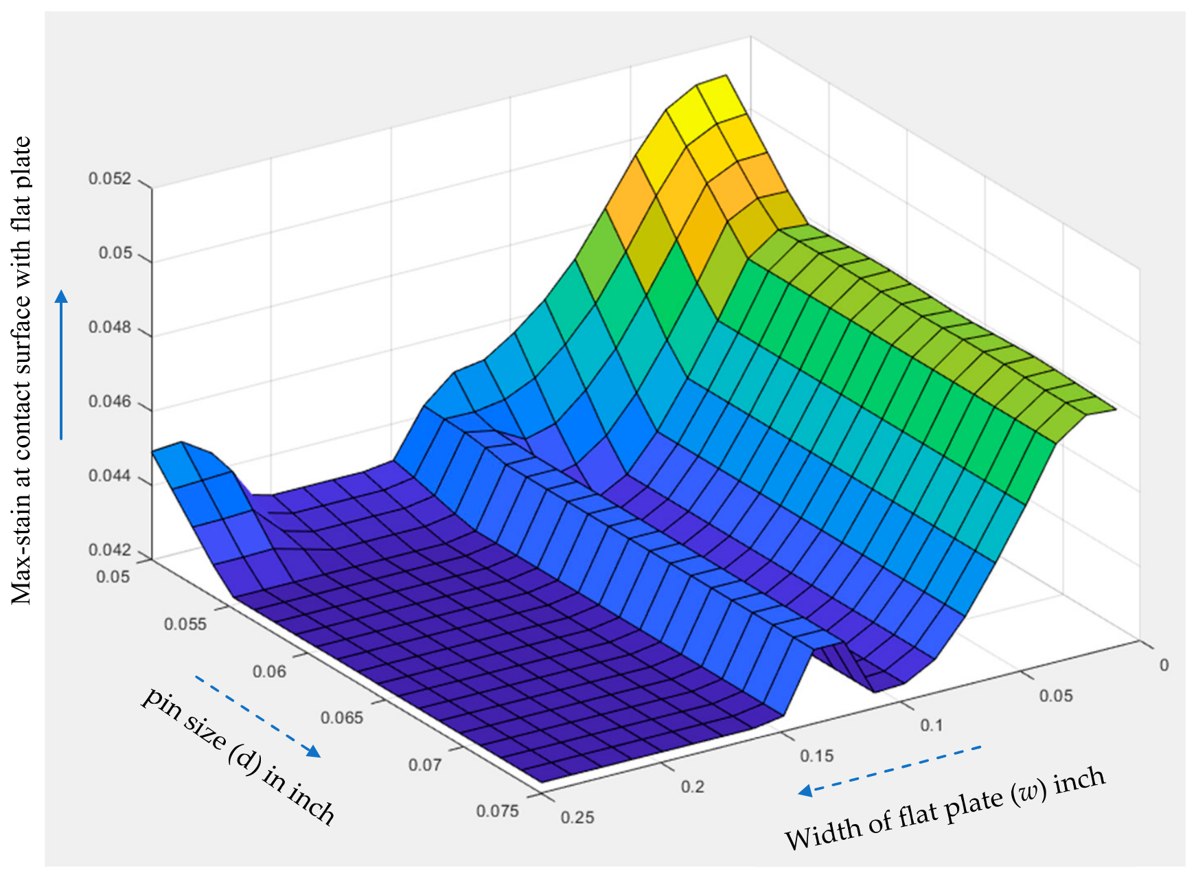
Figure 24.
Max strain at bottom of bone staple versus the size changes in pin and flat plate.
Figure 25.
Max stress over bone staple versus the size changes in pin and flat plate.
Figure 26.
Leg opening size versus the size changes in pin and flat plate.
In contrast, Figure 24 shows that the max strain on the contact of the bone staple with the flat plate is gradually reduced when the width (d) of the flat plate is increased; this is because the effective bearing area at the contact will be increased with an increase in the width. Note that it is critical to monitor the strain distribution at the bridge of the bone staple since it takes a main role in producing compression force in deployment.
Figure 25 displays the max stress and shows the similarities to the max strain in Figure 23 since stresses and strains are associated with each other by constitutive equations even if the materials are non-elastic. Figure 26 shows that subjected to the same loading condition, installing variables such as d and w affect the distributions of stresses and strains and thus the deflection of the whole bone staples.
4. Summary and Conclusions
This study employed a Digital Triad (DT-II) framework combined with nonlinear finite element analysis to evaluate the feasibility of replacing conventional Nitinol with a Ni-free β-Ti alloy in bone staples, while explicitly accounting for installation-induced preloading effects. This work leads to the following main findings:
- (1)
- Ni-free β-Ti alloy can provide clamping forces comparable to Nitinol staples when appropriate installation parameters are applied. Under optimized preloading conditions, the maximum stress and strain remain within the recoverable range of the Ni-free β-Ti alloy, confirming its feasibility as a Nitinol-free alternative for patients with nickel sensitivity.
- (2)
- An inserting operation affects the performance of a bone staple significantly. For example, changes in w significantly affect strain and stress distributions in the staple. A smaller w reduces the global maximum strain caused by bending at the pin–staple contact, while a larger w mitigates localized strain at the plate–staple interface by increasing the bearing area, indicating that w governs the balance between global and local deformation modes. The pin size directly controls stress concentration at the pin–staple contact. An optimal pin diameter (d ≈ 0.060 in this study) minimizes both maximum strain (≈0.089) and maximum stress (≈969 MPa), demonstrating that pin geometry must be treated as a design variable rather than a fixed tooling.
- (3)
- The study confirms that realistic preloading displacements and contact constraints decisively determine strain paths, stress evolution, and the resulting clamping force. Ignoring installation boundary conditions can therefore lead to inaccurate predictions of staple performance and material feasibility.
Overall, the results show that fabrication material, installation parameters (w and d), and boundary conditions form an integrated design space. The proposed DT-II-based methodology provides a systematic and transferable approach for designing and deploying Nitinol-free bone staples with predictable mechanical performance.
It should note that the presented work is at its preliminary stage with a few limitations: (a) the study was focused exclusively on the biomechanical performance of the contiguous bone-staple construct following installation of the staple, and, as such, the performance of the construct post-installation, which has implications for the success of the surgery, was not investigated; (b) in the investigation of the influence of geometrical parameters that are relevant to staple installation, only two were considered, when, in fact, there are many others, such as configuration of the bridge of the staple, staple bridge width, staple leg length, and staple leg taper angle, and (c) our future work will seek to validate the simulation results experimentally to further explore the manufacturability of bone staples using Ni-free-β-Ti alloy.
Author Contributions
Conceptualization, Z.B. and S.C.; methodology, Z.B.; software, Z.B.; validation, S.C. and J.S.; formal analysis, Z.B.; investigation, Z.B.; resources, S.C. and J.S.; data curation, Z.B.; writing—original draft preparation, Z.B.; writing—review and editing, S.C. and J.S. All authors have read and agreed to the published version of the manuscript.
Funding
This research received no external funding.
Data Availability Statement
The supporting data, models, and simulation results are available per request made by the corresponding author due to request from collaborating partner.
Acknowledgments
The corresponding author acknowledges the sponsorship from endorsed Harris Chair in Wireless Communication and Applied Research and Indiana Data Mine (IDM) grant at Purdue University Fort Wayne.
Conflicts of Interest
The corresponding author Zhuming Bi affiliated with Purdue University Fort Wayne, Song Cai and Jeremy Schaffer affiliated with Fort Wayne Metals Research Products, LLC, confirm that this paper has no conflict of interest with any company, or any financial or personal relationship with a third party.
References
- Glasbrenner, J.; Deichsel, A.; Raschke, M.J.; Briese, T.; Frank, A.; Herbort, M.; Herbst, E.; Kittl, C. Bone staples provide favorable primary stability in cortical fixation of tendon grafts for medical collateral ligament reconstruction—A biomechanical study. Orthop. J. Sports Med. 2021, 9, PMC8287377. [Google Scholar] [CrossRef] [Scilit]
- Deichsel, A.; Raschke, M.J.; Herbst, E.; Peez, C.; Oeckenpöhler, S.; Briese, T.; Wermers, J.; Kittl, C.; Glasbrenner, J. The biomechanical stability of bone staples in cortical fixation of tendon grafts for medical collateral ligament reconstruction depends on the implant design. Am. J. Sports Med. 2022, 50, 3827–3831. [Google Scholar] [CrossRef] [Scilit]
- Sanghvi, N.; Vora, D.; Charaya, E.; Patel, J.; Sharma, S. An approach for material selection for bone staple (an orthopedic implant) suing GRA and fuzzy logic. Mater. Today Proc. 2021, 44, 1300–1306. [Google Scholar] [CrossRef] [Scilit]
- Smith, T.F. Chapter 41: The Bone Staple Tried and True Superhero of Bone Fixation. 2010. Available online: https://paperzz.com/doc/7621740/the-bone-staple---the-podiatry-institute (accessed on 1 June 2026).
- Weinstein, R.B.; Bhakta, D. Tarsometatarsal Arthrodesis Using a Novel Orthopedic Staple. 2022. Available online: https://fusemedical.com/wp-content/uploads/2022/07/Orbitum-Case-Report-2022-1-1.pdf (accessed on 1 June 2026).
- Saleeb, A.F.; Dhakal, B.; Owusu-Danquah, J.S. Assessing the performance characteristics and clinical forces in simulated shape memory bone staple surgical procedure: The significance of SMA material model. Comput. Biol. Med. 2015, 62, 185–195. [Google Scholar] [CrossRef] [Scilit]
- Salameh, T.M. Performance of Existing Bone Staples for Treatment of Fractures. Master’s Thesis, Cleveland State University, Cleveland, OH, USA, 2020; p. 1225. Available online: https://engagedscholarship.csuohio.edu/etdarchive/1225 (accessed on 1 June 2026).
- Russell, S.M. Design considerations of Nitinol bone staples. J. Mater. Eng. Perform. 2009, 18, 831–835. [Google Scholar] [CrossRef] [Scilit]
- Al-Takhayneh, O. Rapid Prototyping of Surgical Staples. Master’s Thesis, University of Wollongong Australia, Wollongong, Australia, 2021; pp. 240–245. Available online: https://ro.uow.edu.au/theses1/1422/ (accessed on 1 June 2026).
- Al-Takhayneh, O.; Warren, H.; Panhuis, M.I.H. 3D printing of surgical staples. MRS Adv. 2022, 7, 489–494. [Google Scholar] [CrossRef] [Scilit] [PubMed]
- Rethnam, U.; Kuiper, J.; Makwana, N. Mechanical characteristics of three staples commonly used in foot surgery. J. Foot Ankle Res. 2009, 2, 5. [Google Scholar] [CrossRef] [Scilit]
- Technavio. Latest News—Bone Staple Systems Market: Hospitals is Expected to Lead the End-User Segment During 2025–2029. 2026. Available online: https://newsroom.technavio.org/bone-staple-systems-market-industry-size-analysis (accessed on 16 April 2026).
- Curenton, T.L.; Davis, B.L.; Darnley, J.E.; Weiner, S.D.; Owusu-Danquah, J.S. Assessing the biomechanical properties of nitinol staples in normal osteopenic and osteoporotic bone models: A finite element analysis. Injury 2021, 52, 2820–2826. [Google Scholar] [CrossRef] [Scilit] [PubMed]
- Patel, R.; Moore, W.; Jimenez, J.C. Severe symptomatic nickel allergy following stent graft implantation requiring excision and external iliac artery reconstruction. J. Vasc. Surg. Cases Innov. Tech. 2022, 8, 562–564. [Google Scholar] [CrossRef] [Scilit]
- Cai, S.; Schaffer, J.; Ehle, A.; Ren, Y. A Ni-free β-Ti Alloy with Large and Stable Room Temperature Super-elasticity. Mater. Today Commun. 2021, 26, 101838. [Google Scholar] [CrossRef] [Scilit]
- Dall’Oo, R. In Silico Framework for the Certification of Nitinol Staples. Master’s Thesis, Politecnico Di Torino, Turin, Italy, 2021. Available online: https://webthesis.biblio.polito.it/21713/1/tesi.pdf (accessed on 1 June 2026).
- Zimmer Biomet. Arcus Staple System Surgical Technique. 2024. Available online: https://www.zimmerbiomet.com/content/dam/zb-corporate/en/education-resources/surgical-techniques/specialties/foot-&-ankle/arcus-staple-system/ArcusStapleSurgTechLIT1526Rev041.pdf (accessed on 1 June 2026).
- Milgrom, C.; Finestone, A.; Hamel, A.; Mandes, V.; Burr, D.; Sharkey, N. A comparison of bone strain measurements at anatomically relevant sites using surface gauges versus strain gauged bone staples. J. Biomech. 2004, 37, 947–952. [Google Scholar] [CrossRef] [Scilit] [PubMed]
- Milgrom, C.; Voloshin, A.; Novack, L.; Milgrom, Y.; Ekenman, I.; Finestone, A.S. In vivo strains at the middle of distal thirds of the tibia during exertional activities. Bone Rep. 2022, 16, 101170. [Google Scholar] [CrossRef] [Scilit]
- Majd, M.K.; Bahrami, M.; Nazarpak, M.H.; Nouri, A. Computational modeling of nickel-titanium orthopedic staples in the treatment of a fractured scaphoid: Effects of staple bridge configuration. J. Mech. Behav. Biomed. Mater. 2023, 141, 105777. [Google Scholar] [CrossRef] [Scilit] [PubMed]
- Lekston, Z.; Stróż, D.; Jędrusik-Pawłowska, M. Preparation and characterization of Nitinol bone staples for cranio-maxillofacial surgery. J. Mater. Eng. Perform. 2012, 21, 2650–2656. [Google Scholar] [CrossRef] [Scilit]
- ASTM F2082-06; Standard Test Method for Determination of Transformation Temperature of Nickel-Titanium Shape Memory Alloys by Bend and Free Recovery. ASTM International: West Conshohocken, PA, USA, 2006.
- Frydrýšek, K.; Čepica, D.; Halo, T.; Skoupý, O.; Pleva, L.; Madeja, R.; Pometlová, J.; Losertová, M.; Koutecký, J.; Michal, P.; et al. Biomechanical Analysis of Staples for Epiphysiodesis. Appl. Sci. 2022, 12, 614. [Google Scholar] [CrossRef] [Scilit]
- Halo, T.; Frydrysek, K.; Cepica, D.; Skoupy, O.; Michal, P.; Kraus, S.; Havlas, V.; Kohut, J. Numerical simulation of staples for epiphysiodesis. In Proceedings of the 26th International Conference Engineering Mechanics, Brno, Czech Republic, 24–25 November 2020; pp. 186–189. [Google Scholar]
- Dundar, M.A.; Gunoz, A.; Kepir, Y.; Kara, M.; Avci, A.; Arbag, H. Comparative biomechanical analysis of titanium fixation plates and NiTi shape memory staples for mandibular fracture treatment using finite element method. Biomed. Signal Process. Control 2025, 103, 107501. [Google Scholar] [CrossRef] [Scilit]
- Jia, T.; Leotoing, L.; Guines, D.; Gloriant, T. Modelling of mechanical performance by finite element analysis of compressive bone staples made of superelastic NiTi and Ti-Zr-Nb-Sn alloys. J. Mech. Behav. Biomed. Mater. 2026, 173, 107239. [Google Scholar] [CrossRef] [Scilit]
- ASTM. Standard Specification and Test Methods for Metallic Bone Staples. 2015. Available online: https://www.astm.org/f0564-10r15.html (accessed on 1 June 2026).
- Gillquist, J. Removal of bone staples: A potential problem in revision surgery after ligament reconstruction. Arthrosc. J. Arthrosc. Relat. Surg. 1989, 5, 336–339. [Google Scholar] [CrossRef] [Scilit] [PubMed]
- Ferrara, L.A.; Williams, M.; Katchis, S.D.; Weiner, L.S. A Mechanical Evaluation of the Interfragmentary Compressive Forces of the Arcus Staple System. 2024. Available online: https://www.zimmerbiomet.com/content/dam/zb-corporate/en/products/specialties/foot-&-ankle/arcus-staple-system/ArcusWhitepaper.pdf (accessed on 1 June 2026).
- Russell, N.A.; Regazzola, G.; Aiyer, A.; Nomura, T.; Pelletier, M.H.; Myerson, M.; Walsh, W.R. Evaluation of Nitinol staples for the lapidus arthrodesis in a reproducible biomechanical model. Front. Surg. 2015, 2, 65. [Google Scholar] [CrossRef] [Scilit]
- Carbonaro, D.; Chiastra, C.; Bologna, F.A.; Audenino, A.L.; Terzini, M. Determining the mechanical properties of super-elastic nitinol bone staples through an integrated experimental and computational calibration approach. Ann. Biomed. Eng. 2024, 52, 682–694. [Google Scholar] [CrossRef] [Scilit]
- Balta, E.C.; Pease, M.; Moyne, J.; Barton, K.; Tilbury, D.M. Digital Twin-Based Cyber-Attack Detection Framework for Cyber-Physical Manufacturing Systems. IEEE Trans. Autom. Sci. Eng. 2024, 21, 1695–1712. [Google Scholar] [CrossRef] [Scilit]
- Lesi, V.; Jakovljevic, Z.; Pajic, M. Security Analysis for Distributed IoT-Based Industrial Automation. IEEE Trans. Autom. Sci. Eng. 2022, 19, 3093–3108. [Google Scholar] [CrossRef] [Scilit]
- Proia, S.; Carli, R.; Cavone, G.; Dotoli, M. Control Techniques for Safe, Ergonomic, and Efficient Human-Robot Collaboration in the Digital Industry: A Survey. IEEE Trans. Autom. Sci. Eng. 2022, 19, 1798–1819. [Google Scholar] [CrossRef] [Scilit]
- Conti, C.J.; Varde, A.S.; Wang, W. Human-Robot Collaboration with Commonsense Reasoning in Smart Manufacturing Contexts. IEEE Trans. Autom. Sci. Eng. 2022, 19, 1784–1797. [Google Scholar] [CrossRef] [Scilit]
- Abubakr, M.; Abbas, A.T.; Tomaz, I.; Soliman, M.S.; Luqman, M.; Hegab, H. Sustainable and smart manufacturing an integrated approach. Sustainability 2020, 12, 2280. [Google Scholar] [CrossRef] [Scilit]
- Bi, Z.; Zhang, W.-J.; Wu, C.; Luo, C.; Xu, L. Generic Design Methodology for Smart Manufacturing Systems from a Practical Perspective. Part II—Systematic Designs of Smart Manufacturing Systems. Machines 2021, 9, 208. [Google Scholar] [CrossRef] [Scilit]
- Bi, Z.; Zhang, W.-J.; Wu, C.; Luo, C.; Xu, L. Generic Design Methodology for Smart Manufacturing Systems from a Practical Perspective, Part I—Digital Triad Concept and Its Application as a System Reference Model. Machines 2021, 9, 207. [Google Scholar] [CrossRef] [Scilit]
- Arthrex. Four-Corner Fusion with Dynamite® Staples. 2024. Available online: https://www.arthrex.com/resources/LB1-000299-en-US/four-corner-fusion-with-dynanite-staples?referringteam=foot_and_ankle (accessed on 1 June 2026).
- Stryker. EasyClip: Osteosynthesis Compression Staples Operative Technique. 2024. Available online: https://www.stryker.com/content/dam/stryker/foot-and-ankle/products/easyclip/resources/eu/EC_ST_1_EN.pdf (accessed on 1 June 2026).
- DePuy. Extraordinary Advantages of Extramedullary Innovation. 2024. Available online: https://www.jnjmedtech.com/sites/default/files/user_uploaded_assets/pdf_assets/2020-05/Hammertoe%20Brochure-%203.5.20.pdf (accessed on 1 June 2026).
- Abdulridha, A.; Palermo, D.; Foo, S.; Vecchio, F.J. Behavior and modelling of super-elastic shape memory alloy reinforced concrete beams. Eng. Struct. 2013, 49, 893–904. [Google Scholar] [CrossRef] [Scilit]
- Alipour, A.; Kadkhodael, M.; Ghaei, A. Finite element simulation of shape memory alloy wires using a user material subortine: Parametric study of heating rate, conductivity, and heat convection. J. Intell. Mater. Syst. Struct. 2014, 26, 554–572. [Google Scholar] [CrossRef] [Scilit]
- Kim, N.H. Nonlinear Finite Element Analysis Procedures. 2024. Available online: https://mae.ufl.edu/nkim/egm6352/Chap2.pdf (accessed on 1 June 2026).

Disclaimer/Publisher’s Note: The statements, opinions and data contained in all publications are solely those of the individual author(s) and contributor(s) and not of MDPI and/or the editor(s). MDPI and/or the editor(s) disclaim responsibility for any injury to people or property resulting from any ideas, methods, instructions or products referred to in the content. |
© 2026 by the authors. Licensee MDPI, Basel, Switzerland. This article is an open access article distributed under the terms and conditions of the Creative Commons Attribution (CC BY) license.