


Abstract
As robots and humans start to share common spaces and perform collaborative tasks, it has become critical to facilitate information exchange between them for communicating and interpreting each other’s intentions. By overlaying virtual objects on a view of the physical world, mixed reality (MR) technology offers a compelling approach for designing innovative models of human–robot interaction (HRI). For robot manipulators, mobile MR frameworks that allow a user to communicate a goal position for the robot’s end effector have been widely studied. However, HRI applications that may require other relevant information for the manipulator to complete more complex tasks remain unexplored. Thus, we propose an MR-enhanced HRI framework, deployed on a touchscreen tablet, that utilizes a virtual arrow object to communicate force intent (i.e., location, direction, and magnitude) to the manipulator and provide visual force feedback to the user. To evaluate the system performance and user experience, we conducted a user study with 25 participants who used a manipulator robot to complete four insertion subtasks, reporting a task success score of 96%, a usability overall mean score of 4.35 out of 5, and a low task load index of 21.49 out of 100. The results show that the MR-HRI framework is intuitive to operate, allowing users to successfully perform assigned tasks by effectively communicating their intentions through the virtual arrow.
1. Introduction
Recent advances in robotics technology have enabled robots to move from isolated work cells into spaces shared with human users, allowing them to perform complex tasks that require human–robot collaboration. For this collaboration to succeed, it is paramount to establish effective models for human–robot interaction (HRI) that facilitate communication and coordination during collaborative task execution. These models must enable a diverse range of interaction styles between humans and robots, ranging from direct control, where the user controls the robot’s movements via teleoperation, to collaborative interactions, where the interaction model allows the robot and its user to interpret each other’s intentions [1] intuitively. Force-based HRI is particularly critical in a range of real-world applications. In industrial surface finishing, for instance, collaborative polishing requires a robot to apply a precisely controlled and directed force at each point along a workpiece. In such applications, any deviations in force magnitude or direction can lead to surface defects, thus making it necessary for the operator to communicate to the robot not just a target location but a complete force intent [2]. In a scenario related to healthcare, robotic massage systems must deliver controlled contact forces at specific body locations and orientations to replicate therapeutic techniques, a task where an operator must intuitively specify not only the target site but also the required force and direction [3]. These scenarios highlight the need for HRI systems that allow human operators to convey not only where the robot should act, but also the direction and force with which it should act.
With the recent advent of augmented reality (AR) and mixed reality (MR) technologies, researchers have sought to develop HRI models to provide visual feedback by overlaying computer-generated graphics on a representation of the physical world. Such an approach to visual augmentation and virtual object design can support robotics explorations along multiple avenues, e.g., robot programming, real-time navigation and control, safety enhancement, intent communication, and enhancing a robotic system’s expressiveness [4,5,6,7,8].
In the context of human–robot collaboration, an MR-enhanced HRI interface renders visual cues that facilitate spatial dialogue and communication between human and robot collaborators for manipulating physical objects in a shared 3D space [9]. Recent efforts have explored the effectiveness of and user experience with MR applications (apps) for collaborative tasks. Specifically, experimental setups that resemble particular activities have been proposed [10,11,12], in which a human and a robot collaborate and communicate through an MR system. The approaches in [10,11,12] have been experimentally validated by measuring relevant performance metrics (e.g., task time completion, efficiency, and user mental load). The MR interfaces of [10,11,12] allow users to intuitively control the robot using virtual objects overlaid on the real-world scene. At the same time, the task-performing robotic system can communicate its intent in real time via virtual displays embedded in the shared 3D space, indicating its status and the status of the task being performed. Prior collaborative HRI solutions have shown that an operator can intuitively control a robotic system to move to a specific pose and perform pick-and-place operations with low cognitive load (e.g., [10,12,13]). Recent MR-HRI work continues this trend, focusing on 3D pose specification [14], robot trajectory planning [15], and motion generation [16], with force-based intent communication remaining rare and largely confined to specialized surgical or teleoperation contexts [17]. Consequently, tasks that require users to specify the location, direction, and magnitude of an applied force, such as inserting a component into a tight-fitting socket or assembling mating parts, are not addressed by the existing MR-HRI approaches. These scenarios require the user to communicate both the target pose of the end effector and the precise amount and direction of force to be applied at a specific point on a selected object. The robot, in turn, must monitor and indicate whether the required force has been achieved.
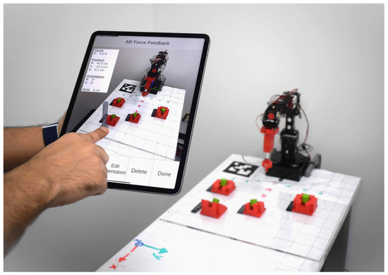
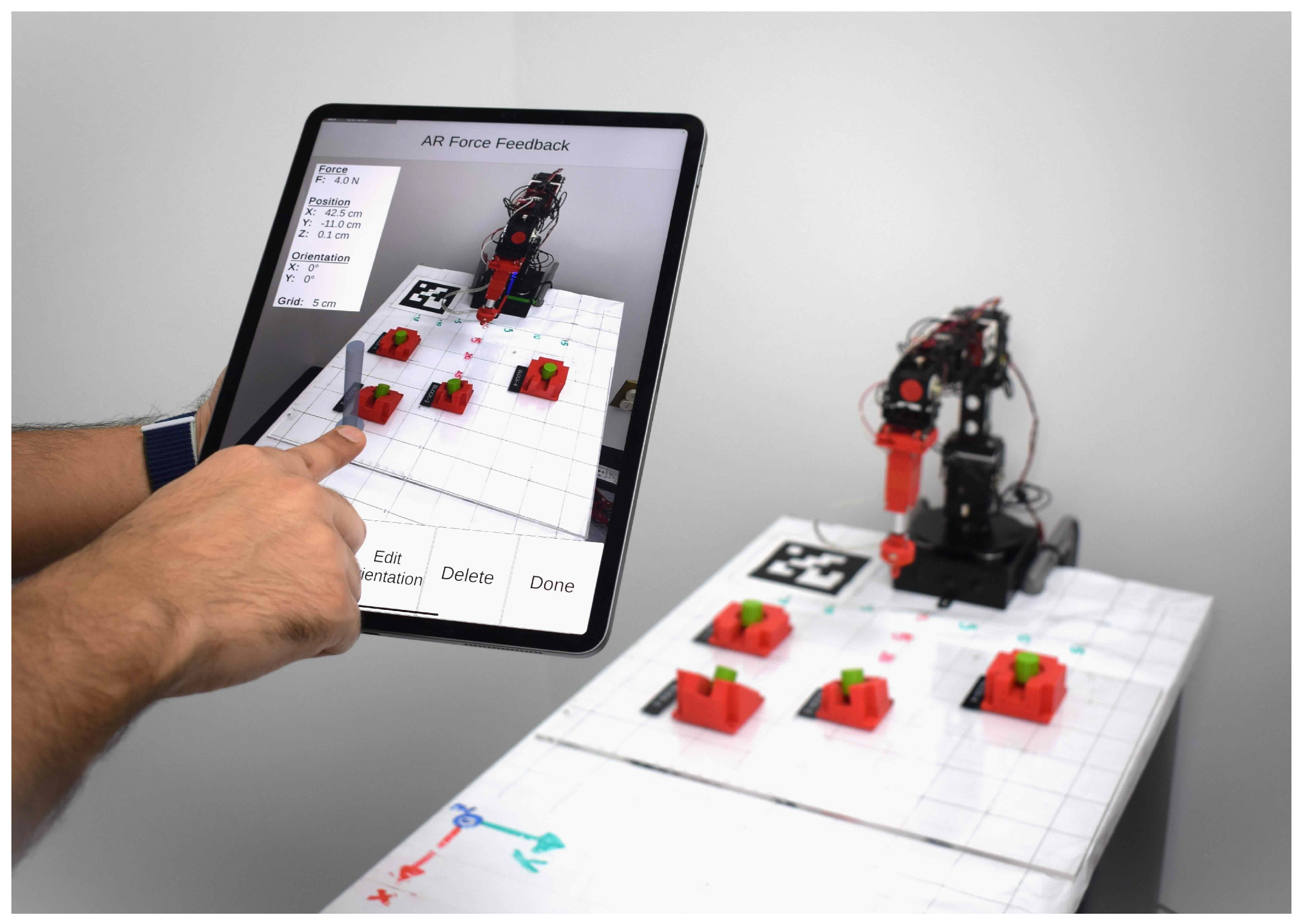
To address the aforementioned gap, this paper proposes a novel MR-HRI framework deployed on a mobile touchscreen tablet that extends user intent communication beyond end-effector pose specification to include force-based intent. Specifically, the framework introduces a virtual arrow paradigm in which a single interactive object encodes the location, direction, and magnitude of a desired contact force, and provides real-time visual force feedback to close the interaction loop. Unlike prior MR-HRI approaches that are limited to controlling robot position [10,11,12], the proposed system enables operators to intuitively specify force intent through touch gestures on a tablet, without requiring specialized haptic hardware. As shown in Figure 1, using a touch gesture-enabled MR app on a tablet, a user can spawn a virtual arrow object overlaid on the real-world scene captured by the tablet’s camera and modify the arrow’s characteristics to intuitively control the robotic system. To do so, the user can interact with the arrow object to adjust its position, orientation, and length, thereby specifying the location, direction, and magnitude parameters, respectively, of the force to be applied by the robot. As the robot executes the force instruction, a virtual disc object is spawned along the virtual arrow and begins to move in proportion to the force applied by the end effector. This visual representation permits the user to verify whether the user-specified force magnitude has been applied. We validate this approach by evaluating the user experience and usability of the proposed system with 25 participants.
Figure 1.
The proposed MR-HRI framework for force intent communication. A user interacts with a touchscreen running the MR app, which overlays virtual objects onto the live camera feed of the physical workspace and displays task information, including applied force, end-effector position, and orientation. Force parameters are specified through touch-based manipulation of a virtual arrow object, while a moving virtual disc provides visual force feedback during execution. The physical setup in the image shows a robotic manipulator within a gridded workspace with target objects.
This paper is organized as follows. Section 2 reviews related work on haptic feedback and visual force feedback. Section 3 describes the methodology employed in the design of the proposed MR framework. Section 4 presents the results of experiments and user studies. Section 5 provides concluding remarks and suggests directions for future research.
2. Related Work
In this section, we review prior efforts related to haptic feedback in the domains of robotics and AR, including visual haptic feedback and visual force feedback.
2.1. Haptic Feedback in Robotics
In HRI tasks involving robot teleoperation, the high-level planning and cognitive decision-making are assigned to the human operator. In contrast, the mechanical aspects of the task are executed by the robot [18]. To increase telepresence and enhance task execution performance, haptic interfaces aim to replicate the tactile experience of perceiving or manipulating a real environment using complex mechatronics-based devices [19]. Haptic feedback has important applications in surgical robotics, where its benefits have been studied by Hooshiar et al. [20]. However, the highly controlled environment of a medical setting may not be replicable for collaboration tasks involving parts assembly in manufacturing. Moreover, the use of haptic devices may significantly increase production-line costs.
2.2. Haptic Feedback in AR
In AR systems, delivery of haptic feedback to a user may entail instrumenting objects, workspaces, surfaces, or the user with active devices (actuators or signal generators) that engender a sophisticated tactile sensation to enhance the AR or MR experience as in the work of Bau and Poupyrev [21]. Nonetheless, for AR-enhanced HRI, instrumenting the environment or user may be infeasible due to implementation costs, power consumption, or an ever-changing collaborative workspace. Moreover, such methods may not offer quantitative information about force feedback. Thus, in this work, we used visual cues rather than tactile feedback to provide quantitative force information.
2.3. Visual-Only Haptic Feedback
The approach to visually communicate haptic information for HRI varies based on the device hosting the application (head-mounted, eye-worn, spatial, or robot-attached), the methods used to capture user gestures (image or touch), and whether the user interacts with a virtual or real object. For example, Reddy and Rompapas [22] proposed to create a visual effect at the contact point between the user’s finger and the virtual object. However, as a virtual reality method, this approach is not viable for an AR or MR environment wherein a physical robot is guided to interact with real objects. Moreover, the technique of Reddy and Rompapas [22] relies on head-mounted displays (HMD) and image-captured hand gestures, which are not applicable if a physical robot’s end effector is expected to interact with real objects. We developed an MR app for a handheld tablet that is more cost-accessible than HMDs. Moreover, we limited the input mode to touch-based gestures to create virtual objects overlaid on the real-world scene as seen on the tablet. These user-spawned virtual objects provide the robot with end-effector pose and force information. Such an MR-based HRI interface allows a human operator to share the same environment as the robot without touching physical objects that may be unsafe (e.g., toxic to skin contact, high-temperature). Finally, feedback on the force applied by the robot is conveyed to the user through visual cues, as outlined below.
2.4. Visual Force Feedback
Research in medical robotics on robot-assisted knot tying with fine suture materials has found that visual force feedback is helpful for novice robotic surgeons [23,24]. Specifically, in the work of Reiley et al. [24], a da Vinci surgical robotic system [25] was instrumented with force sensors to measure forces applied at each instrument’s tip. To effectively communicate to the user the force applied by the robot to the knot, the system superimposes two semitransparent circle displays on the instrument tips. These displays change color to green, yellow, or red depending on the force level: minimal, ideal, or excessive, respectively. In this work, instead of mapping the applied force to colors, we mapped it to a visual cue consisting of a virtual disc that moves in proportion to the amount of force applied by the end effector along the opposite direction of its approach vector.
The works reviewed above address complementary but distinct aspects of MR-enhanced HRI. Collaborative MR frameworks [10,11,12,13] have demonstrated that users can intuitively control robot position and pose with low cognitive load, but the prior works do not address force-based intent communication, as their target applications do not require it. Visual force feedback approaches of Jourdes et al. [23] and Reiley et al. [24] have shown the utility of conveying force information visually, but they rely on specialized surgical platforms and haptic instrumentation that are not suited to general collaborative HRI. The proposed framework bridges these two lines of work by enabling a user to specify force intent (location, direction, and magnitude) through touch interactions on a mobile tablet, while receiving real-time visual force feedback, without requiring specialized haptic hardware.
3. Materials and Methods
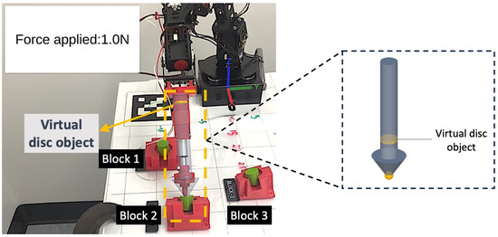
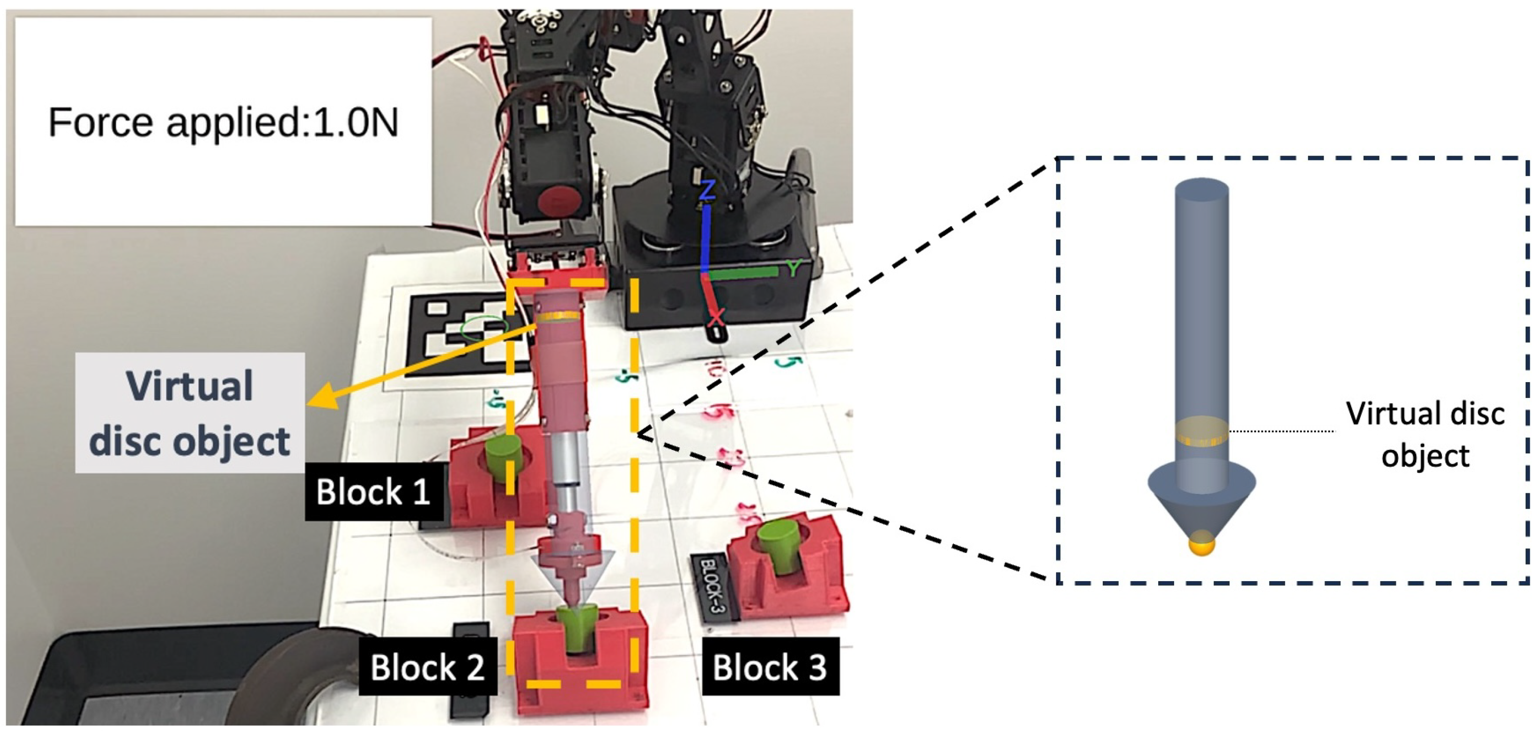
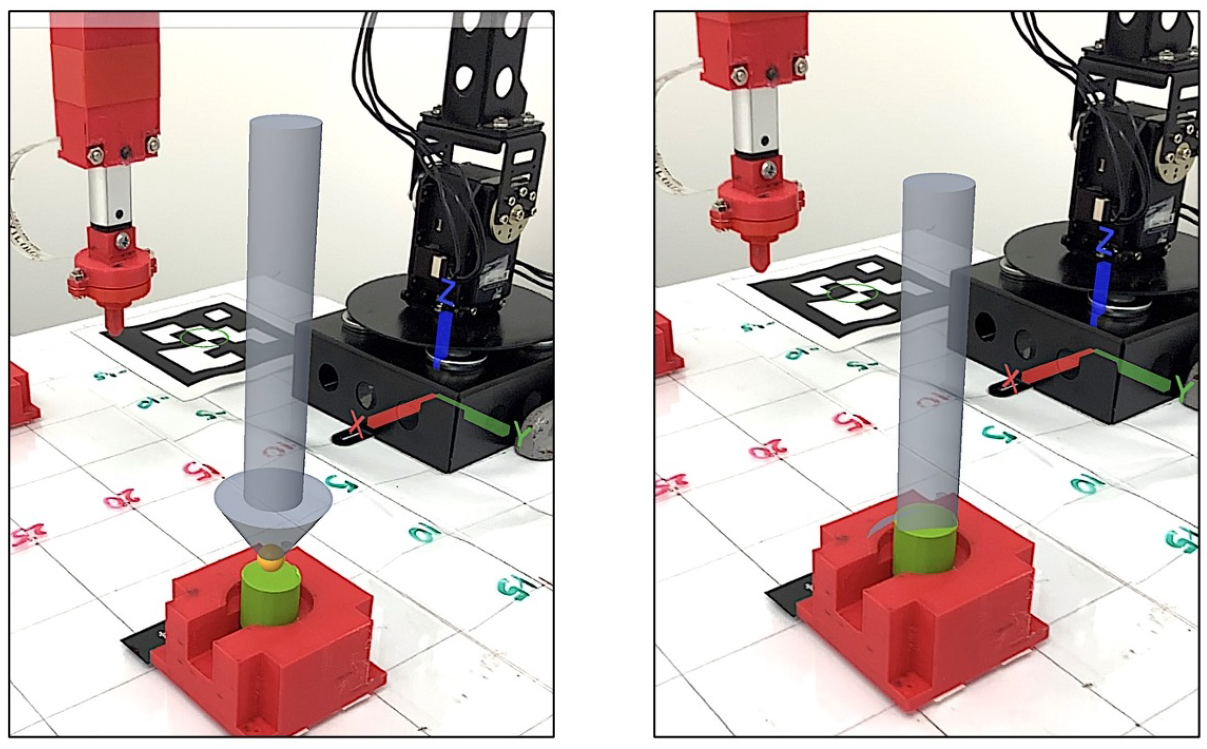
Our testbed consists of a 7-degree-of-freedom (DoF) robot whose end-effector is equipped with a linear actuator and a force sensor. This robot is controlled by an MR-enabled app deployed on a tablet. Through touch interactions in the app, the user creates a virtual arrow and uses it to intuitively instruct the robot to apply a specific amount of force at a desired location in a specific direction. Upon receiving the user instructions, the end effector moves to the required pose. Next, the linear actuator extends the end-effector tip until the applied force is equal to or greater than the user-specified force. When the robot initiates its motion, a virtual disc object is spawned on the app at the target location, as shown in Figure 2. To provide a visual cue proportional to the force sensor measurement, this virtual disc moves in the direction opposite to the end-effector approach vector.
Figure 2.
Visual force feedback during task execution. The virtual disc object is overlaid at the target location on the live camera feed and moves in proportion to the force applied by the end effector (1.0 N shown). The enlarged view (right) details the virtual disc object positioned along the arrow shaft.
3.1. Robotic System
In this subsection, we provide brief overviews of the hardware, software, and control components used for the robotic manipulator of this work.
3.1.1. Hardware
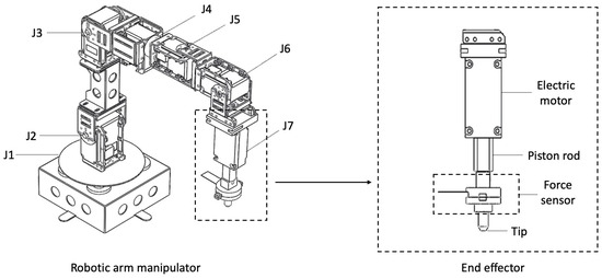
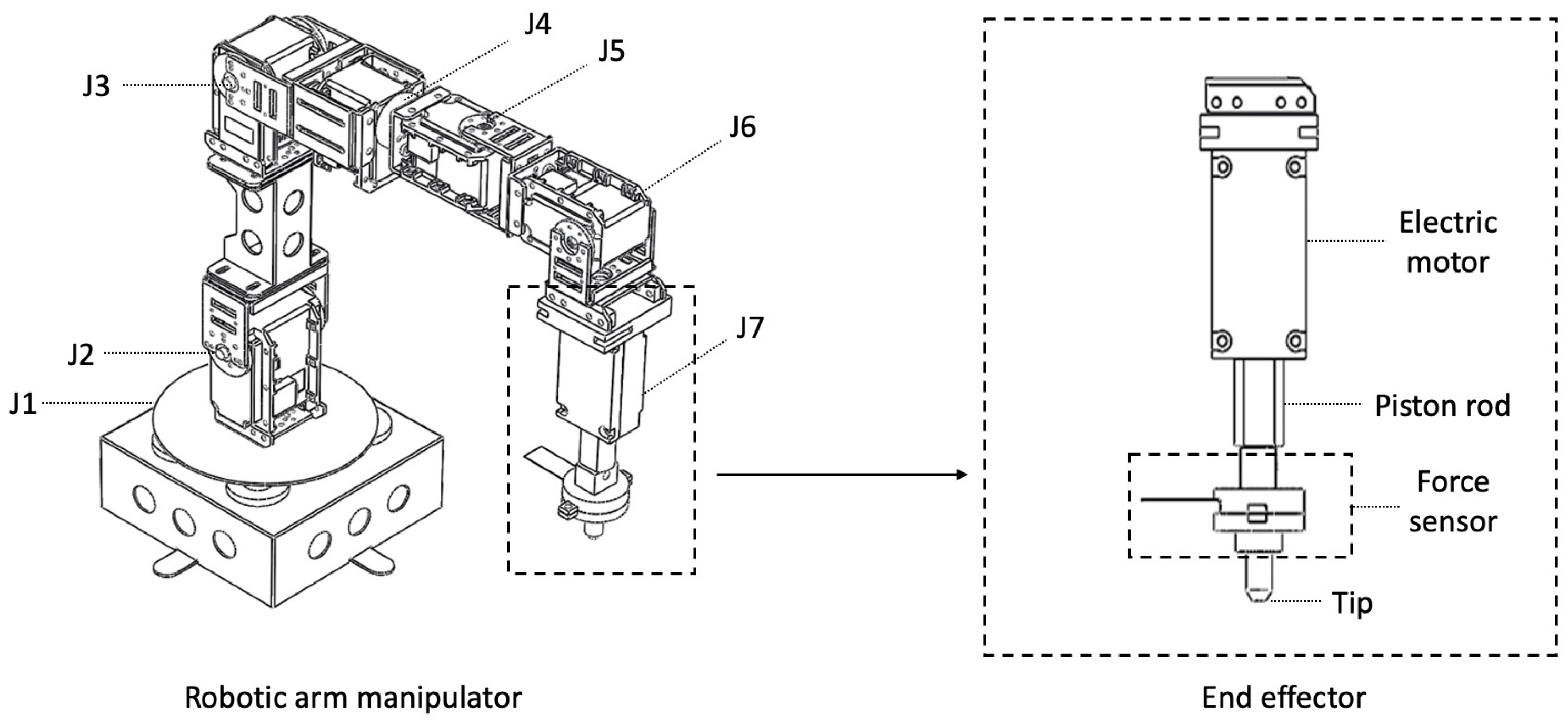
As shown in Figure 3, the 7-DoF robot consists of a kinematic chain of lightweight aluminum links, with six revolute joints driven by MX-106 (one), MX-64 (two), and MX-28 (three) Dynamixel motors (Robotis, Seoul, Republic of Korea) and one linear joint driven by a 1.2 inch stroke-4.5 lbs force DC House linear actuator (DC House, Xiamen, China). A U2D2 USB-to-Serial adapter allows the Dynamixel motors to be controlled by a desktop computer running ROS Noetic on Ubuntu 20.04. At the end of the robot’s last link, a 3D-printed end effector is driven by the linear actuator and controlled by an Arduino Nano microcontroller. The end effector is equipped with a FlexiForce A201 force sensor (Tekscan, Boston, MA, USA) to measure the reaction forces experienced by its tip. The microcontroller acquires and processes the force measurements and communicates with the ROS environment.
Figure 3.
The 7-DoF robotic arm manipulator (left) with six revolute joints (J1–J6) driven by Dynamixel motors and one linear joint (J7) driven by a DC House linear actuator. The enlarged view (right) details the 3D-printed end effector, comprising an electric motor, a piston rod, a FlexiForce A201 force sensor, and a 3D-printed tip.
3.1.2. Software and Control
The robot assembly was 3D-modeled and exported as a Unified Robot Description Format (URDF) file, which was used to configure the robot system using the motion planning and control packages available in the MoveIt framework of ROS. To enable seamless operation with the rest of the kinematic chain, the microcontroller that manages the end effector’s actuation and measurement communicates with ROS via the ROSSerial protocol, facilitating data exchange and synchronization over the USB port. To control the robot, the ROS controller expects a pose (position and orientation) and an end-effector force value from the user interface (UI). Upon receiving a user control command, the robot performs a sequence of actions to move the end effector to the commanded pose within its workspace. It extends the end-effector tip using the linear actuator until the commanded force is reached. Once the force sensor detects that the commanded force has been reached, or if the linear actuator is fully extended without the end-effector tip making surface contact, the linear actuator retracts. The robot then returns to its home position, where it waits for the next control command.
3.2. MR App
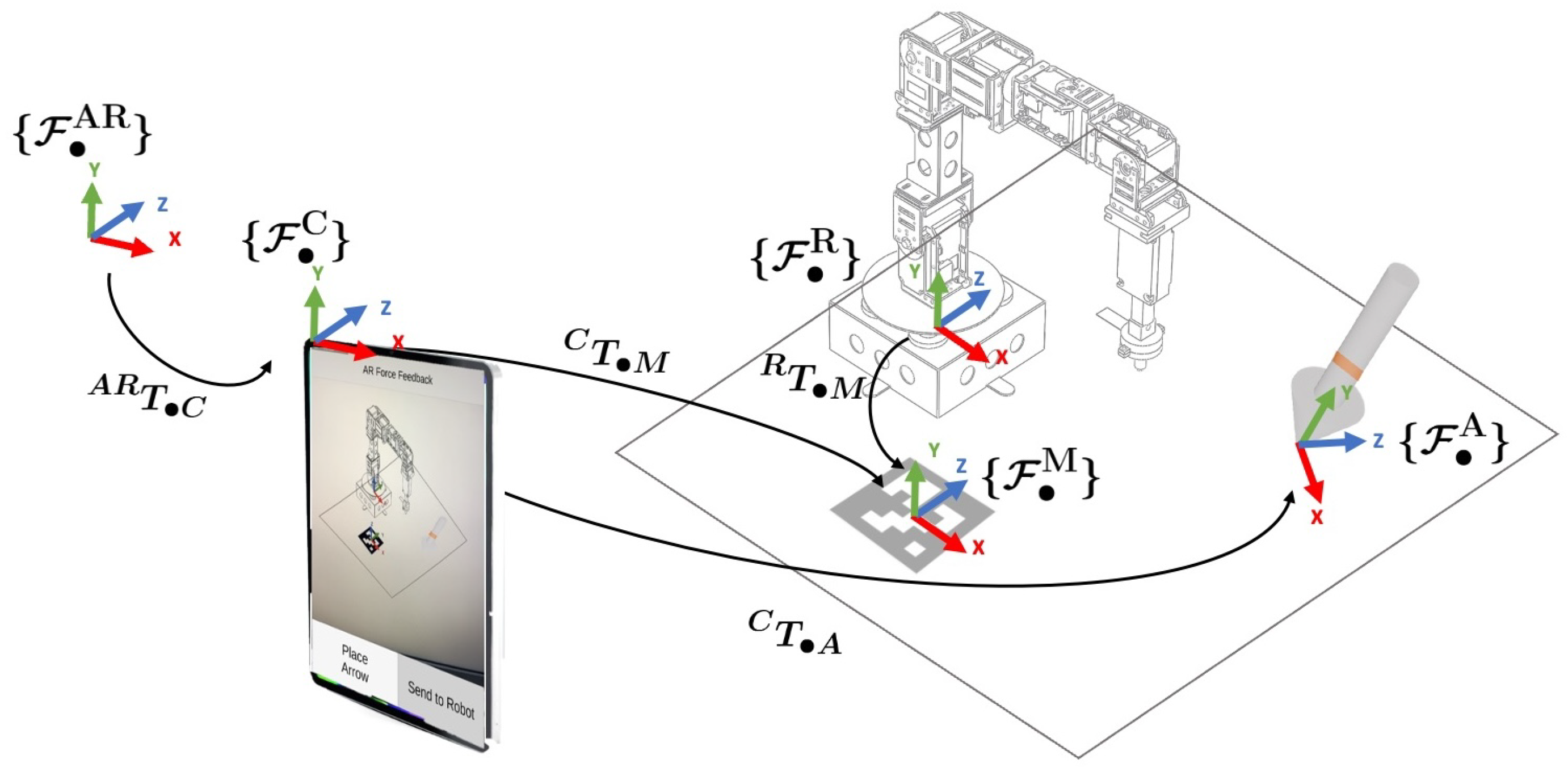
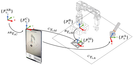
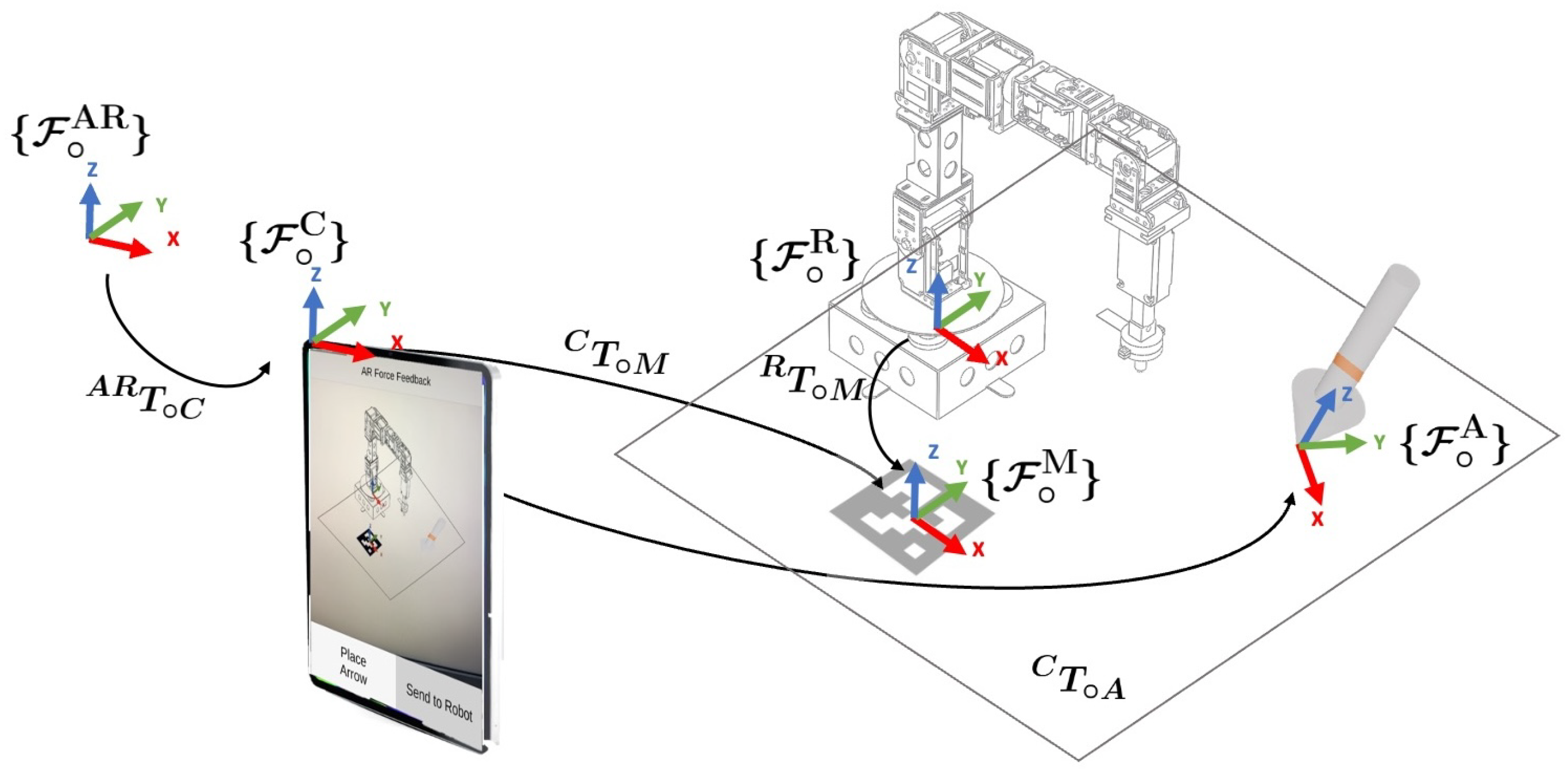
The MR-enabled app was developed using the Unity game engine (Version: 2021.3.17f1) and the AR Foundation framework (Version: 4.2.7), with a 4th-generation 12.6-inch iPad Pro serving as the deployment platform. The AR Foundation framework provides access to the platform’s native AR and MR features, including ARKit XR Plug-in (Version: 4.2.7) functionality for iOS devices. When the app launches, the origin of the coordinate frame for the AR session is set to the location of the tablet’s camera coordinate frame . The coordinate frame serves as a fixed reference for tracking the tablet’s camera, detected features (e.g., corners, edges, and point clouds), planes, and virtual object poses. Every time the MR app spawns a virtual object P, it is initialized relative to with a pose . Since the app tracks the tablet’s camera pose relative to , the corresponding transformation allows the pose of the virtual object to be represented in using As an illustrative example, in the case of a virtual arrow, the app spawns the arrow with the pose relative to . Then, relative to , the app tracks the pose of the arrow by using the transformation
Since the robot manipulates real objects, defining a common reference between the MR app and the real world is necessary. To do so, following a strategy similar to that of Chacko and Kapila [10], the app switches to the Scan Mode and prompts the user to locate and select a fiducial marker in the environment. Relative to the robot’s real-world coordinate frame , this marker has the pose that is provided to the app a priori. Moreover, this fiducial marker is conveniently located on a plane that is coincident with the robot’s base. Once the fiducial marker is detected, the app registers the marker pose relative to and assigns a virtual anchor object to it. Next, the app transitions to the Main Mode. Note that the anchor object requires the app to continuously track and update the marker’s pose throughout the current session.
In the Main Mode, the user can tap the Place Arrow button to create a virtual arrow anywhere in the robot’s workspace seen on the device display. Using the pixel coordinate of the screen position tapped by the user, the app performs raycasting on the robot’s workspace to detect the plane hit by the ray and spawns a virtual arrow at the corresponding position. The virtual arrow is assigned a coordinate frame aligned with the robot’s reference frame , and is initialized with a force magnitude (i.e., arrow length) of 1.5 N.
Having created the virtual arrow object, the app transitions to the Edit Mode, where the user can use drag-and-drop gestures to reposition the virtual arrow in the robot’s workspace. Additionally, the UI provides a menu of buttons that the user can use to select a specific force parameter to adjust (e.g., the location of force application, the force orientation, and the force magnitude to be applied by the robot), all via pinch gestures. The user can also delete the current virtual object or select the Done button upon finishing the virtual arrow modification process.
3.3. Virtual Arrow Parameters
The virtual arrow serves as the primary interaction object through which the user encodes all three parameters of force intent. Specifically, the position of the arrow in the scene specifies the point on a selected object at which the force is to be applied. The orientation of the arrow defines the direction in which the force is applied. Finally, the length of the arrow encodes the desired force magnitude. This three-parameter encoding allows a complete force-interaction goal to be specified by a single, spatially located virtual object, as described in the following subsections.
3.3.1. Position
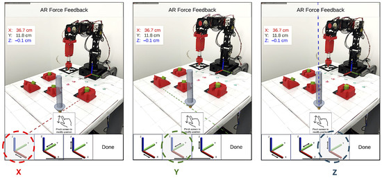
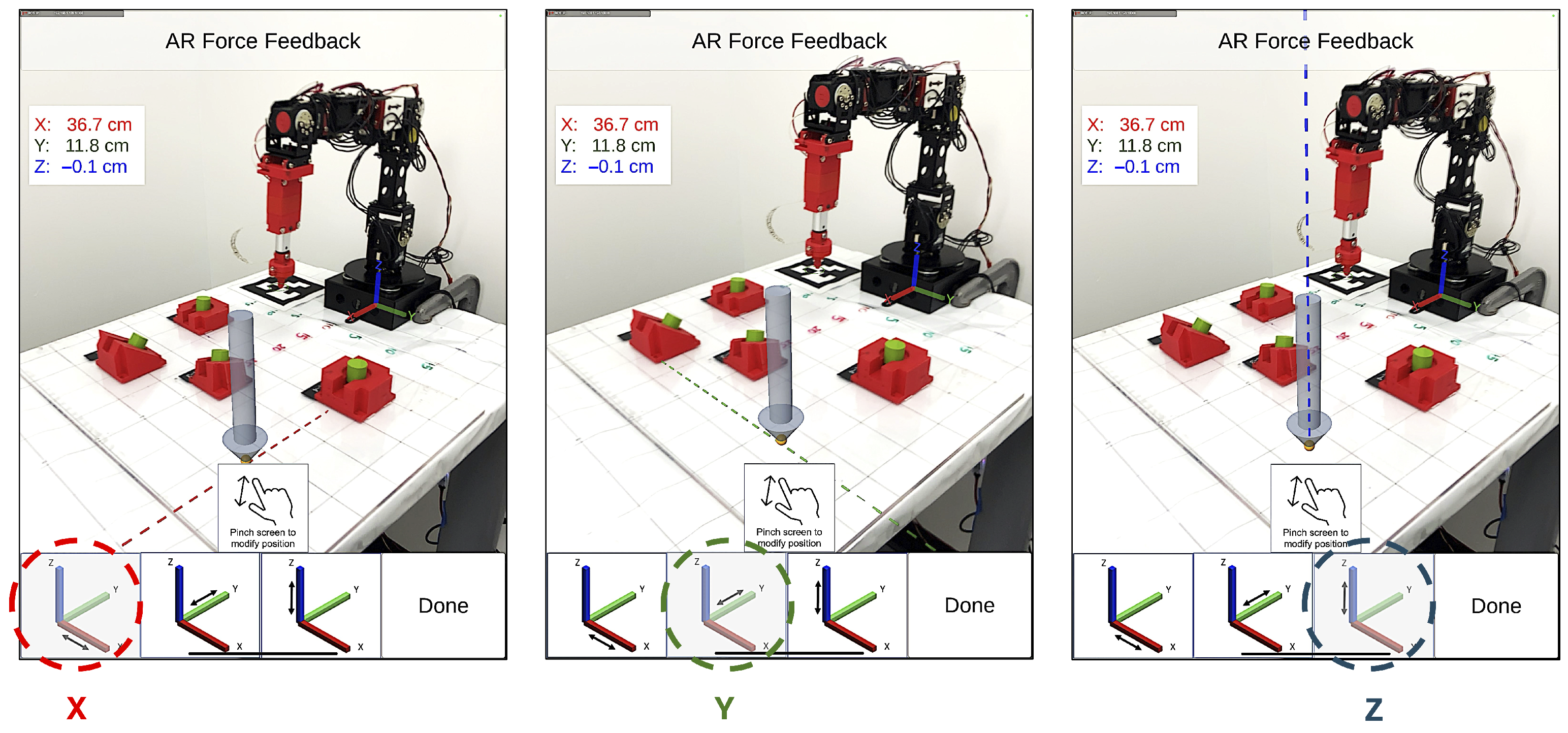
To fine-tune the arrow placement, the user can adjust the arrow’s position along the axes, one axis at a time, as illustrated in Figure 4. The app displays a virtual axis aligned with the direction along which the arrow is being adjusted. The coordinate values displayed on the UI are relative to the robot coordinate frame .
Figure 4.
Arrow position adjustment along the (X) (left), (Y) (center), and (Z) (right) axes. The active axis is highlighted in the bottom toolbar, and a virtual axis line is overlaid on the scene to guide placement. Coordinate values displayed on the UI are relative to the robot coordinate frame.
3.3.2. Orientation
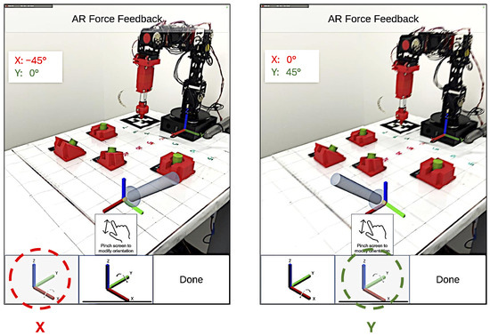
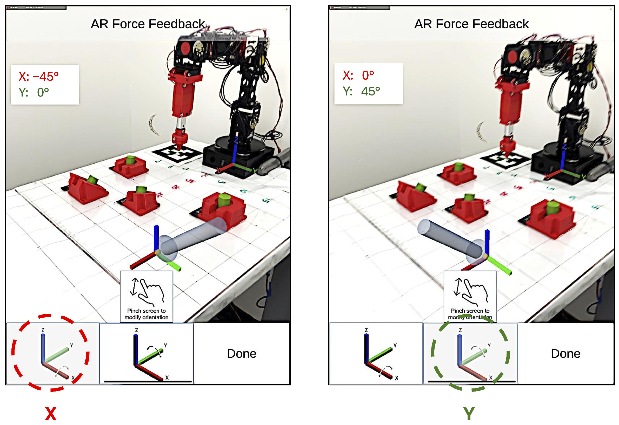
As illustrated in Figure 5, as the user begins editing the arrow’s orientation, a virtual guide coordinate frame is created at the tip of the virtual arrow to help the user identify the reference axis around which the arrow is to be rotated. The orientation of the arrow is adjusted by rotating it around the X– or Y–axis of , where the X–Y plane is parallel to the robot base plane.
Figure 5.
Arrow orientation adjustment around the X–axis (left, X: ) and Y–axis (right, Y: ). The active rotation axis is highlighted in the bottom toolbar, and a virtual guide coordinate frame is overlaid at the arrow tip to indicate the reference axis.
3.3.3. Force
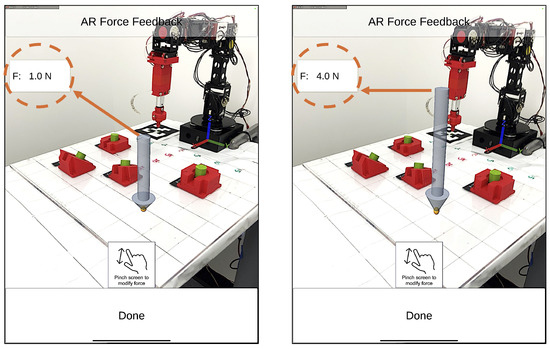
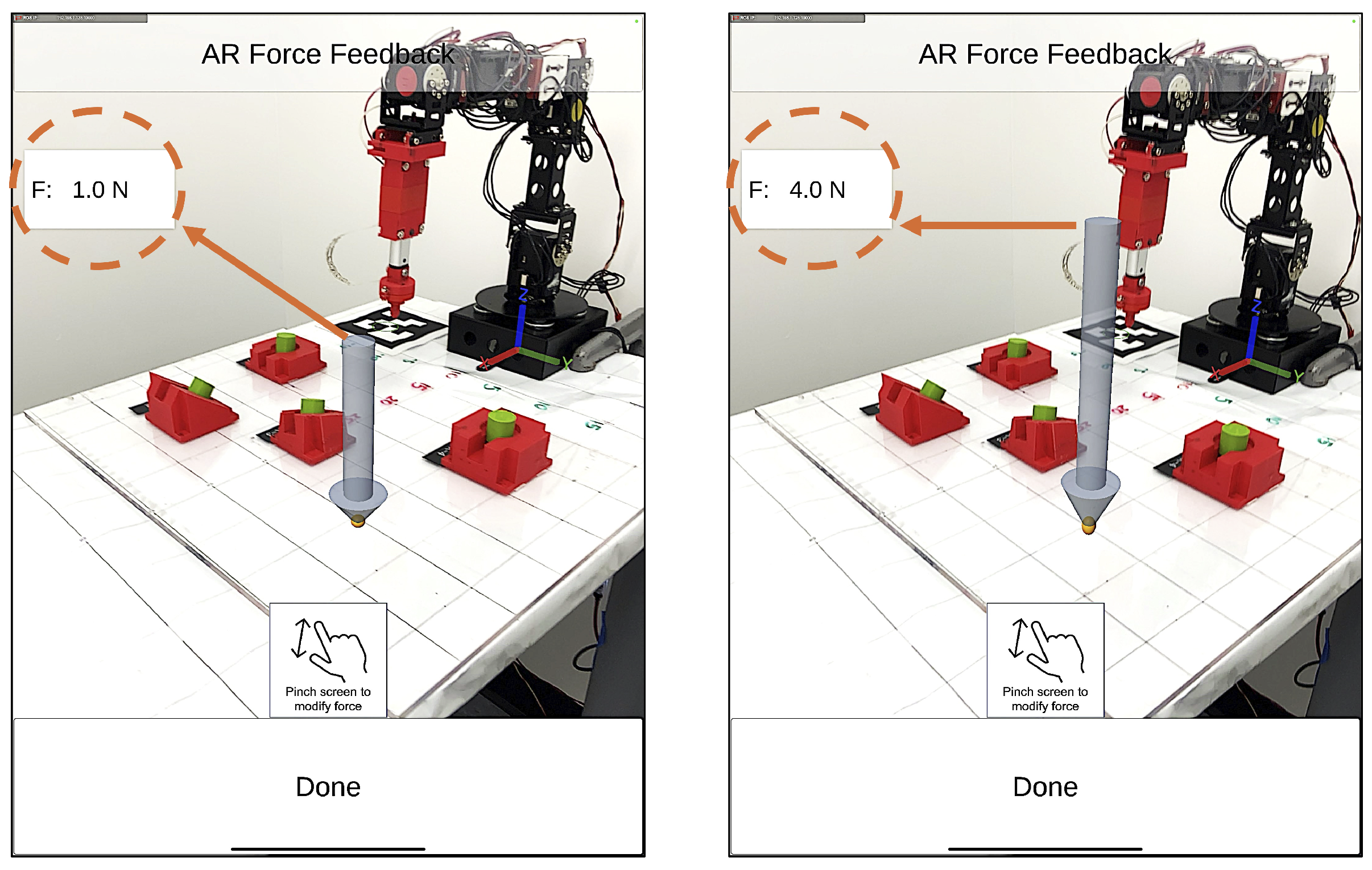
As shown in Figure 6, the length of the virtual arrow corresponds to the amount of force the robot is to apply to the selected object. The interface allows the user to set the force magnitude within a defined range, from 1.0 N to 4.0 N in 0.1 N increments.
Figure 6.
Force magnitude adjustment via arrow length, shown at 1.0 N (left) and 4.0 N (right). The displayed force value (F) updates accordingly as the user pinches the screen to modify the arrow length.
3.4. AR Occlusion Feature
The iPad Pro tablet used in this work is equipped with a LiDAR sensor that continuously captures a mesh of the surrounding geometry. This mesh enables AR occlusion, whereby virtual objects occluded by the real-world geometry are detected by the sensor. As shown in Figure 7, by leveraging the interference between the captured mesh of real objects and the virtual arrow, the user can more accurately estimate the virtual arrow’s position in the robot workspace relative to real objects in the scene, enabling a more realistic and spatially accurate interaction.
Figure 7.
AR occlusion of the virtual arrow enabled by the LiDAR-captured mesh of the real-world geometry. Without occlusion (left), the virtual arrow passes through the target block, while with occlusion enabled (right), the block obscures the arrow tip, helping the user more accurately estimate the arrow’s position relative to real objects in the scene.
3.5. MR App Coordinate System
Since Unity uses a left-handed (LH) coordinate system, its use in AR requires that the poses and pose transformations of all objects in the mobile app adopt the LH coordinate system, as illustrated in Figure 8. For an arbitrary reference frame , we use the notation as its representation in the LH coordinate system. Now, to transform the pose of the virtual arrow from to in the MR app, we utilize where all poses and transformations are represented in the LH coordinate system.
Figure 8.
Coordinate frame transformations in the LH coordinate system used by the MR app, showing the relationships between the AR session , camera , marker , robot , and arrow coordinate frames.
Next, robotics applications commonly use a right-handed (RH) coordinate system. Thus, as shown in Figure 9, to communicate the object pose information to the robot or to display it to the user in the UI, an appropriate transformation is required to convert the poses from the LH to the RH representation. For an arbitrary reference frame , we use the notation as its representation in the RH coordinate system.
Figure 9.
Coordinate frame transformations after conversion to the RH coordinate system, required for communicating pose information to the robot and displaying it in the UI.
Note that in the LH and RH coordinate frames, the X-axis is aligned in the same direction, whereas the Y- and Z-axes are switched. Thus, a homogeneous vector , originally represented in the LH coordinate system, assumes the following representation in the RH coordinate system: . For such a conversion, the following transformation can be used where is a row (or column) swapping permutation matrix [26] given by
Now, let denote an arbitrary homogeneous transformation matrix represented in the LH coordinate system as follows
Then, using Equation (1), the equivalent RH coordinate representation for of (2) is computed as:
Finally, applying Equation (3) to the homogeneous transformation given in the LH coordinate frame yields its RH coordinate frame representation, i.e., .
3.6. Communication Between MR App and Robot
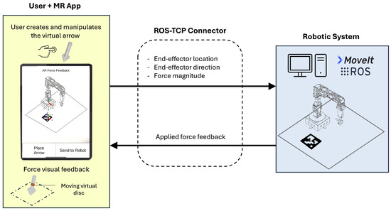
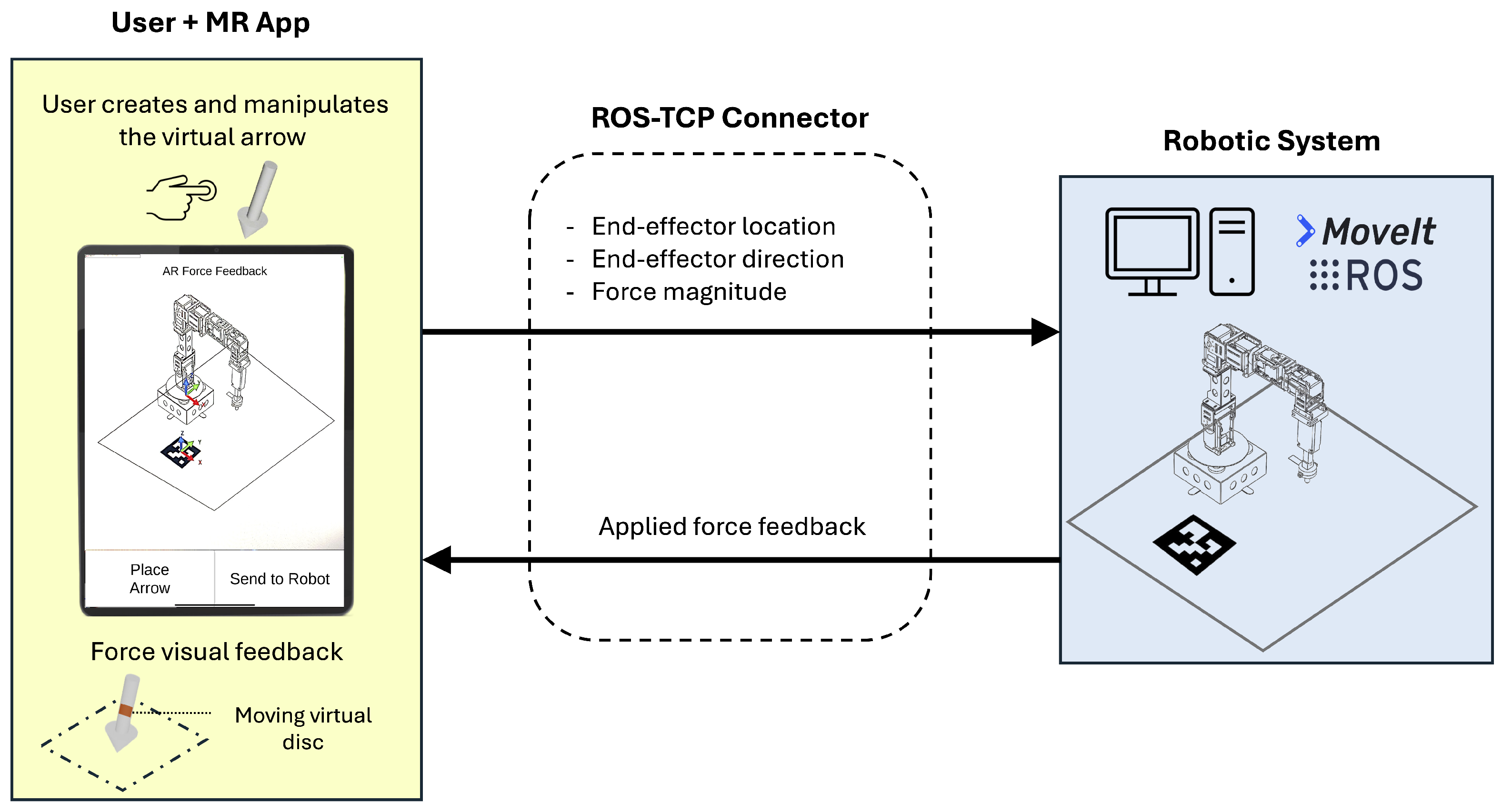
With the MR app and the robotic system connected to the same local network via the Unity-Technologies/ROS-TCP-connector (Release 0.7.0), upon being launched, the app searches for the user-specified IP address of the robotic system. Once connected, the ROS environment can receive control commands from the app. The pipeline from user input to robot control proceeds as follows. The user places and adjusts the virtual arrow on the tablet screen using touch gestures (tap to place, drag to reposition, pinch to modify orientation and force magnitude). The arrow’s pose in the scene is tracked in the AR session coordinate frame and transformed into the robot coordinate frame via the LH-to-RH coordinate conversion described in Section 3.5, yielding the end-effector target pose and force magnitude as a single control command. This command is transmitted to the ROS controller once the user presses the Send to Robot button. The robot then moves its end effector to the specified pose and extends the linear actuator until the force sensor indicates that the commanded force has been reached, at which point the applied force value is streamed back to the app and rendered as the virtual disc’s movement. After executing the user command, the robot returns to its home position and waits for the next control command. Note that the MR-HRI framework of this work operates in a “command-response mode”: force intent parameters are transmitted once, on demand, upon the user confirming the control command via the Send to Robot button, and the applied force feedback is subsequently streamed continuously from the robot to the app during task execution, driving the real-time movement of the virtual disc. While the communication latency of this pipeline was not formally characterized in this work, the system exhibited no perceptible delays during the user study. A formal examination of communication latency is identified as a direction for future work. The overall communication architecture is illustrated in Figure 10.
Figure 10.
Communication architecture between the MR app and the robotic system via the ROS-TCP connector. The app transmits end-effector location, direction, and force magnitude to the robotic system, which returns applied force feedback, rendered in the app as the moving virtual disc.
4. Evaluation Results
In this section, we provide the evaluation results from (i) a series of experimental tests that measured the performance of the robotic manipulator and (ii) a user study that measured participant success and experience under the MR-HRI framework.
4.1. System Performance
In this subsection, we provide the results from three series of experiments, with one series each focusing on the position, orientation, and force performance of the robotic manipulator control.
4.1.1. Position
To assess the robot positioning performance, we used a Microsoft Surface Pro 4 touchscreen display located in the robot’s workspace and equipped the robot end effector with a touchscreen stylus. Using the MR app on the iPad Pro tablet, the end effector was commanded to position itself 20 times at each of two user-specified positions on the Microsoft Surface touchscreen, and the corresponding pixel coordinates were recorded. The position accuracy and repeatability, as given by Mihelj et al. [27], were calculated as follows: accuracy was computed as the Euclidean distance between the commanded pose and the barycenter of the cluster of recorded pixel values, while repeatability was determined by the radius of the minimum enclosing circle centered on the cluster barycenter. The recorded pixel values were then converted to millimeters using the Microsoft Surface touchscreen display’s pixel resolution. As shown in Table 1, the accuracy was 1.64 mm and 2.07 mm at positions P1 and P2, respectively, while the repeatability was 0.55 mm and 0.28 mm. These results confirm that the robotic system’s positioning performance is sufficient for the force applications tasks considered in this work, with force being applied on cylindrical blocks of 20 mm diameter.
Table 1.
Accuracy and repeatability.
4.1.2. Orientation
The robot’s performance in moving its end effector to a commanded orientation was evaluated using cosine similarity between the commanded and measured approach vectors. Cosine similarity was chosen as it directly quantifies the angular agreement between two vectors, yielding a value of 1 for perfect alignment. To measure the actual approach vector, a PhidgetsSpatial 10441B IMU (Phidgets, Calgary, AB, Canada) was installed on the end effector and calibrated. To assess the reliability of the IMU measurements, the goniometry method from RajKumar et al. [28] was used to estimate the root mean squared error (RMSE) and the coefficient of determination () for each rotation axis. The RMSE values were 2.12, 1.23, and 0.72 degrees for the X, Y, and Z rotation axes, respectively, and the values were 0.998, 0.999, and 0.999 for the X, Y, and Z rotation axes, respectively, indicating a strong correlation between the angles set on the goniometer and IMU-measured angles. Two different orientations were then tested 20 times each, with the results reported in Table 2. The cosine similarity mean of 0.999 and near-zero standard deviation (STD) at both orientations confirm that the end effector consistently achieved the commanded approach direction. Finally, Table 2 also provides the orientation accuracy in degrees that captures the difference between the commanded orientation versus the achieved mean orientation. Here, the low values of standard deviation indicate that the achieved mean orientations had relatively small variances. These results demonstrate that the robotic system achieves sufficient orientation accuracy to apply force along the direction commanded by the user.
Table 2.
Orientation accuracy.
4.1.3. Force
To evaluate the robot’s force application performance, two 3D-printed blocks, one with a flat surface and one with an inclined surface, were equipped with force sensors and placed in the robot’s workspace. The robot was instructed to apply force perpendicular to the surface of each block at two commanded force levels (2.0 N and 3.0 N), repeating each condition 20 times. As reported in Table 3, the end-effector force measurements show a mean close to the commanded values with near-zero standard deviation across all conditions. Alternatively, the testbed force sensor measurements show slightly higher mean and standard deviation, likely due to contact variability. These results confirm that the robotic system reliably applies the commanded force across both flat and inclined surfaces. This performance was taken into account when designing the user study tasks, in which participants used the MR app to control the robot to push cylindrical inserts, with a top surface 20 mm in diameter, into hollowed 3D-printed blocks by applying a specified force.
Table 3.
Force performance.
4.2. User Study Tasks and User Experience
The user study had 25 participants, including 19 male and six female users with the following age ranges: 18: 4; 19–24: 10; 25–34: 9; 35–44: 1; and 45–54: 1. Every user was given a brief tutorial on how to use the MR interface, along with an explanation of the programmed features (i.e., UI, AR occlusion, etc.) and a description of three tasks to be performed. After completing the tasks, the participants completed a usability questionnaire and a NASA-TLX questionnaire to evaluate subjective workload from the use of the interface.
The first and second tasks listed below were designed to cultivate user familiarity with the MR app and the robotic system. In the first task, the user had to spawn a virtual arrow, modify its location to the coordinate (25, −6, 8) cm and its orientation to (X: 10, Y: −12) deg, using the editing options available in the UI. Then the user had to send the control command to the robot, which, in response, would move and position its end effector to match the commanded pose and move the end effector’s linear actuator, without the tip contacting any surface. This task aimed to familiarize the user with the app’s interface for changing the arrow’s pose properties. Next, in the second task, the user had to locate the virtual arrow at the coordinate (20, 5, 0), its orientation to (X: 0, Y: 0) deg, and modify the amount of force to be applied by the robot to . Since the position of the arrow is at the same level as the robot’s base, the end effector would make contact with the table where the robot’s base is located, allowing the user to visualize the force feedback information in the MR app. All 25 participants completed the two familiarization tasks successfully.
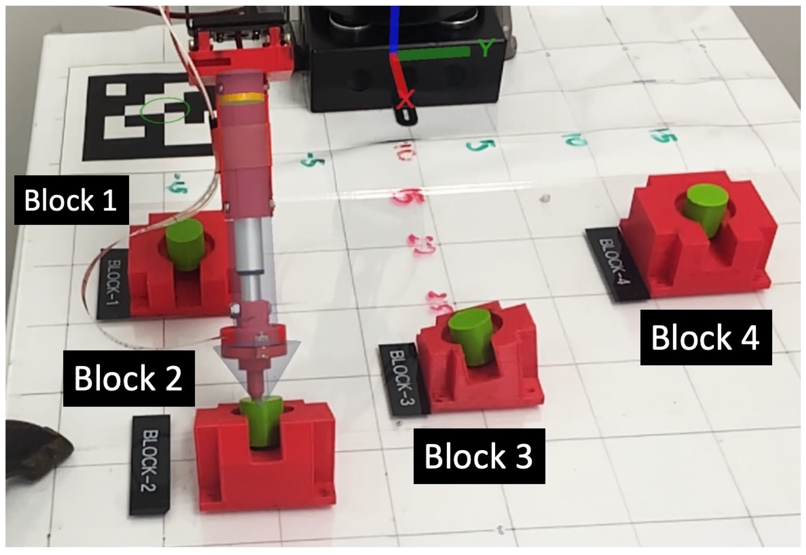
The third task required the user to place the virtual arrow on top of green inserts that fit into a set of 3D-printed red blocks and apply a specified force on each insert, as shown in Figure 11. In this task, the user was not given information about the location or orientation of inserts and had to rely on the apparent pose of the virtual arrow in the real world, as seen on the tablet screen. Blocks 1 and 4 have a flat surface parallel to the workspace plane. Block 2 has a surface rotated −35 degrees around the Y-axis of and block 3 has a surface rotated −15 degrees around the Y-axis and 15 degrees around the X-axis of . For the inclined blocks, the user must orient the virtual arrow correctly to apply a force perpendicular to the block surface and effectively push the insert. This task consisted of the following four subtasks:
Figure 11.
The four 3D-printed red blocks used in Task 3 of the user study. Blocks 1 and 4 have a flat surface parallel to the workspace plane. Block 2 has a surface rotated around the Y-axis and block 3 has a surface rotated around the Y-axis and around the X-axis of . Each block contains a green cylindrical insert that the user must push by commanding the robot to apply a specified force perpendicular to the block surface.
- Apply 1.0 N force to push the insert into block 1
- Apply 3.5 N force to push the insert into block 2
- Apply 2.0 N force to push the insert into block 3
- Apply 3.0 N force to push the insert into block 4
The third task assessed users’ ability to communicate their intentions to the robot via the MR app and evaluated the system’s ability to execute user control commands accurately. Out of the four subtasks, two users missed one subtask each (i.e., failed to accurately locate the virtual arrow on top of the insert), and one user missed two subtasks, yielding a success score of for the four insertion subtasks across the 25 users.
After completing all three tasks, users were asked to respond to a 5-point Likert-scale survey. The survey consisted of 10 questions, six positively directed, four negatively directed, and one open-ended feedback question.
- 1.
- The user interface was easy to use.
- 2.
- It took me a long time to become familiar with the user interface.
- 3.
- I was able to easily modify the “Force-Arrow” characteristics using this interface.
- 4.
- I needed additional assistance from an experienced individual to operate the robot effectively.
- 5.
- The robot reached the goal positions I requested.
- 6.
- The system was unnecessarily complex.
- 7.
- The robot accurately applied the forces I requested.
- 8.
- Learning to use this system required a significant investment of time and effort.
- 9.
- The “object occlusion” feature was helpful to locate the tip of the insert accurately.
- 10.
- Overall, I was able to clearly communicate my intentions to the robot using the user interface.
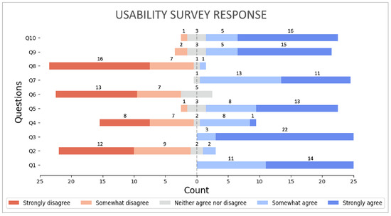
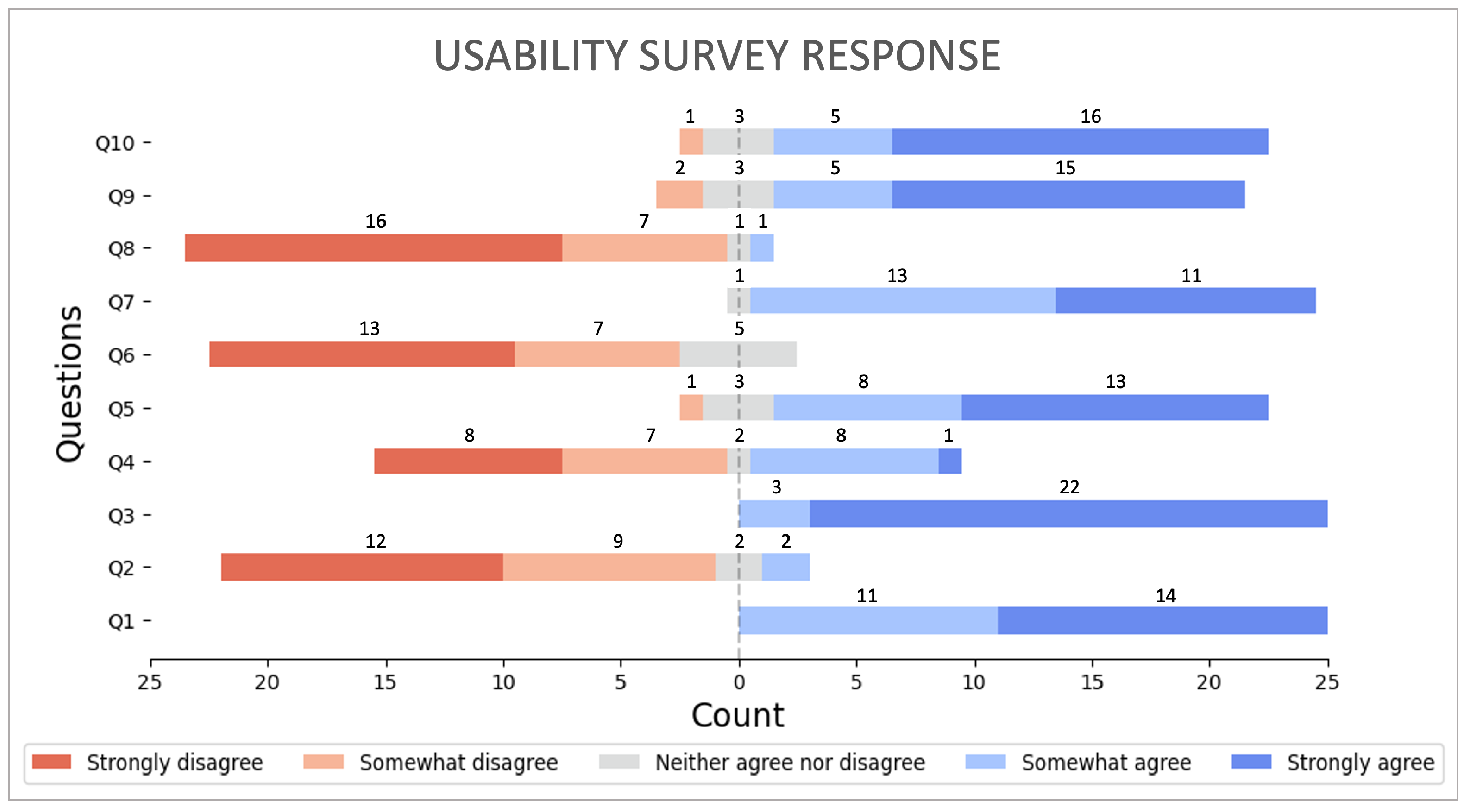
Figure 12 summarizes the user feedback from the usability questionnaire, revealing a positive perception among the participants regarding the MR app. Responses were scored on a 1–5 Likert scale, with negative questions reverse-scored, yielding an overall mean of 4.35 out of 5. For the six questions with positive phrasing, of respondents expressed positive views (agreed or strongly agreed). Likewise, for the four questions phrased negatively, over of participants conveyed favorable opinions (disagreed or strongly disagreed). Question 3 (Q3) received the strongest and most consistent response (mean 4.88, STD 0.32), indicating that the participants found the virtual arrow characteristics easy to modify. Q4 showed the greatest variability (mean 3.52, STD 1.33), suggesting that opinions on the need for additional assistance were more divided, which may reflect differences in the participants’ prior experience with robotics or AR systems.
Figure 12.
Usability survey responses from 25 participants on a 5-point Likert scale. Positively phrased questions (Q1, Q3, Q5, Q7, Q9, Q10) are expected to trend toward agreement (right), while negatively phrased questions (Q2, Q4, Q6, Q8) are expected to trend toward disagreement (left).
Regarding the open-ended user feedback, most participants commented that they could easily modify the characteristics of the arrow. A few participants commented that, although they could accomplish the tasks, the pinching gestures to edit the arrow characteristics were not intuitive. They suggested using slider bars or numerical inputs, which may be considered for future versions of the MR app. Some participants reported that the arrow position changed as they moved around the robot workspace, leading to confusion when positioning the virtual arrow over the inserts. This apparent movement happens when the user moves the tablet too fast, causing the on-board sensor to drift, that may make the virtual arrow’s apparent position deviate from the real-world location. To overcome this effect, the participants were advised to use the grid lines of the physical robot’s workspace as a reference to aid their position estimation before sending the control command to the robotic system.
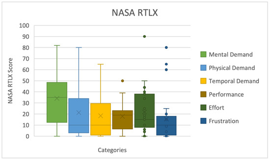
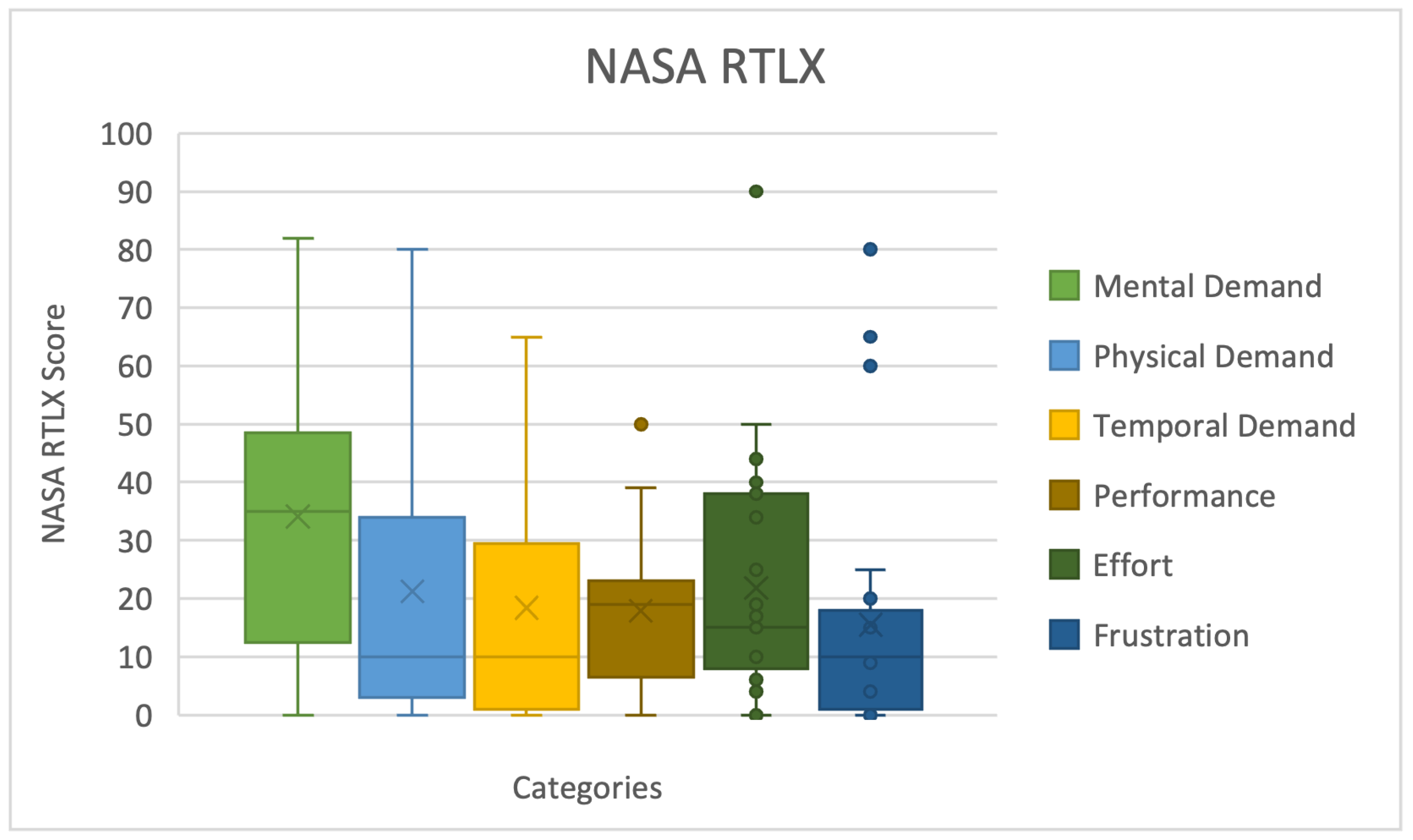
The users were also asked to respond to a survey of NASA Raw Task Load Index (RTLX) [29], which helps assess the interface’s workload implications. This comprehensive workload evaluation was calculated by rating six subscales: mental, physical, and temporal demands, as well as performance, effort, and frustration. Each of these subscales was rated on a 100-point scale by the participants. Note that in RTLX, five of the six subscales are positively directed (higher score implies greater demand, effort, frustration, etc.), and the performance subscale is negatively directed (lower score implies better performance). The results are summarized in Figure 13. The overall composite score, computed as the unweighted mean across all six subscales, was 21.49 out of 100, indicating a low overall workload. Among individual subscales, frustration yielded the lowest mean score (), followed by performance (), suggesting that the participants found the system neither frustrating nor difficult to use effectively. Mental demand had the highest mean score () and the widest spread, indicating greater variability in cognitive load among the participants. Overall, the results indicate that the MR app imposed a low workload on the participants while enabling effective robot control.
Figure 13.
NASA RTLX scores across the six workload subscales for 25 participants. Five subscales are positively directed (higher score implies greater demand), while the performance subscale is negatively directed (lower score implies better performance).
5. Conclusions and Future Work
In this paper, we proposed a mobile-based MR approach that allows users to intuitively communicate to a manipulator robot the magnitude and direction of a force to be applied on a specific point on a selected object, while the robotic system provides visual force feedback when executing the received instruction. This approach was demonstrated for the control of a 7-DoF manipulator (see an illustrative demonstration at https://youtu.be/0O_A1iywVPY, accessed on 29 March 2026) and tested with 25 participants who successfully performed tasks consisting of pushing inserts into 3D-printed blocks. The participants found the MR framework easy to use and quickly familiarized themselves with the UI, as evidenced by a mean usability score of 4.35 out of 5 and a low NASA RTLX composite workload score of 21.49 out of 100. Using a virtual arrow, manipulating its position, and modifying its characteristics to communicate the amount and direction of a force was demonstrated to be an effective strategy to convey the user’s intent for the experimental tasks, resulting in most participants being able to perform them successfully.
Several limitations of this study should be noted. The custom end-effector used in this work restricts the applied force to a narrow range (1.0 to 4.0 N), which limits the system’s applicability for tasks demanding higher contact forces. Because the framework was developed around a custom-built manipulator, its generalizability to commercially available collaborative robot arms requires revalidation of both the communication pipeline and the control interface. The AR session coordinate frame is also susceptible to sensor drift during fast tablet movement, which can cause the virtual arrow’s position to deviate from its intended real-world location, as reported by several participants. Even though this issue can be addressed by using additional fiducial markers distributed across the workspace, such a solution may be impractical in real-world deployments. The user study was conducted in a controlled laboratory setting using a fixed set of 3D-printed push-insertion tasks, which may not reflect the full variability encountered in real-world force-based manipulation. Finally, while the 25-participant sample yields useful usability evidence, it is modest in size. Larger and more diverse samples will be needed to support broader claims about user performance and learnability. The present study also does not include inferential statistical tests or comparisons against alternative interface modalities, such as HMD-based or controller-based force specification, both of which are valuable directions for future work. Moreover, the communication latency of the pipeline between the MR app and the robotic system was not formally characterized in this work. Its measurement and optimization represent a direction for future investigation, particularly for applications where response time is critical.
Future work will explore the UI design of the MR app interface to enhance the user experience and enrich the collaborative experience when executing specific tasks. Doing this will require capturing information about the workspace environment and the objects to be manipulated. In addition, information about the robotic system will be communicated to the user through intuitive visual cues.
Author Contributions
Conceptualization, C.L. and V.K.; methodology, C.L., K.R.R. and V.K.; software, C.L. and K.R.R.; validation, C.L. and K.R.R.; formal analysis, C.L.; investigation, C.L. and V.K.; resources, V.K.; data curation, C.L. and K.R.R.; writing—original draft preparation, C.L. and K.R.R.; writing—review and editing, V.K.; visualization, C.L. and K.R.R.; supervision, V.K.; project administration, V.K.; funding acquisition, V.K. All authors have read and agreed to the published version of the manuscript.
Funding
This research was supported in part by the National Science Foundation grant number FW-HTF 2026479.
Data Availability Statement
The article includes original contributions from a study. Further inquiries can be directed to the corresponding author.
Acknowledgments
The authors thank the mechatronics, controls, and robotics laboratory (MCRL) students for their valuable feedback during the development of the robotic system and the MR app. The authors also thank D. Rivadeneira, a UX/UI designer, for helpful feedback.
Conflicts of Interest
The authors declare no conflicts of interest.
Abbreviations
The following abbreviations are used in this manuscript:
| AR | Augmented reality |
| DoF | Degree of freedom |
| HMD | Head-mounted display |
| HRI | Human–robot interaction |
| IMU | Inertial measurement unit |
| LH | Left-handed |
| MR | Mixed reality |
| RH | Right-handed |
| RMSE | Root mean squared error |
| RTLX | Raw Task Load Index |
| STD | Standard deviation |
| UI | User interface |
| URDF | Unified robotics description format |
References
- Mutlu, B.; Roy, N.; Šabanović, S. Cognitive Human-Robot Interaction. In Springer Handbook of Robotics; Siciliano, B., Khatib, O., Eds.; Springer International Publishing: Cham, Switzerland, 2016; pp. 1907–1934. [Google Scholar]
- Zhou, H.; Zhang, X.; Liu, J. A corrective shared control architecture for human–robot collaborative polishing tasks. Robot. Comput. Integr. Manuf. 2024, 92, 102876. [Google Scholar] [CrossRef] [Scilit]
- Yang, J.; Lim, K.H.; Mohabbat, A.B.; Fokken, S.C.; Johnson, D.E.; Calva, J.J.; Do, A.; Mueller, M.R.; Chon, T.Y.; Bauer, B.A. Robotics in Massage: A Systematic Review. Health Serv. Res. Manag. Epidemiol. 2024, 11, 23333928241230948. [Google Scholar] [CrossRef] [Scilit]
- Bambušek, D.; Materna, Z.; Kapinus, M.; Beran, V.; Smrž, P. Combining Interactive Spatial Augmented Reality with Head-Mounted Display for End-User Collaborative Robot Programming. In Proceedings of the IEEE International Conference on Robot and Human Interactive Communication (RO-MAN), New Delhi, India, 14–18 October 2019; pp. 1–8. [Google Scholar] [CrossRef] [Scilit]
- Carriero, G.; Calzone, N.; Sileo, M.; Pierri, F.; Caccavale, F.; Mozzillo, R. Human-Robot Collaboration: An Augmented Reality Toolkit for Bi-Directional Interaction. Appl. Sci. 2023, 13, 11295. [Google Scholar] [CrossRef] [Scilit]
- Groechel, T.; Shi, Z.; Pakkar, R.; Matarić, M.J. Using Socially Expressive Mixed Reality Arms for Enhancing Low-Expressivity Robots. In Proceedings of the IEEE International Conference on Robot and Human Interactive Communication (RO-MAN), New Delhi, India, 14–18 October 2019; pp. 1–8. [Google Scholar] [CrossRef] [Scilit]
- Makhataeva, Z.; Zhakatayev, A.; Varol, H.A. Safety Aura Visualization for Variable Impedance Actuated Robots. In Proceedings of the IEEE/SICE International Symposium on System Integration (SII), Paris, France, 14–16 January 2019; pp. 805–810. [Google Scholar] [CrossRef] [Scilit]
- Walker, M.; Hedayati, H.; Lee, J.; Szafir, D. Communicating Robot Motion Intent with Augmented Reality. In Proceedings of the ACM/IEEE International Conference on Human-Robot Interaction (HRI), Chicago, IL, USA, 5–8 March 2018; pp. 316–324. [Google Scholar] [CrossRef] [Scilit]
- Green, S.A.; Billinghurst, M.; Chen, X.; Chase, J.G. Human-robot collaboration: A literature review and Augmented Reality approach in design. Int. J. Adv. Robot. Syst. 2008, 5, 1. [Google Scholar] [CrossRef] [Scilit]
- Chacko, S.M.; Kapila, V. An Augmented Reality Interface for Human-Robot Interaction in Unconstrained Environments. In Proceedings of the IEEE/RSJ International Conference on Intelligent Robots and Systems (IROS), Macau, China, 3–8 November 2019; pp. 3222–3228. [Google Scholar] [CrossRef] [Scilit]
- Chan, W.P.; Hanks, G.; Sakr, M.; Zuo, T.; der Loos, H.F.V.; Croft, E. An Augmented Reality Human-Robot Physical Collaboration Interface Design for Shared, Large-Scale, Labour-Intensive Manufacturing Tasks. In Proceedings of the IEEE/RSJ International Conference on Intelligent Robots and Systems (IROS), Las Vegas, NV, USA, 25–29 October 2020; pp. 11308–11313. [Google Scholar] [CrossRef] [Scilit]
- Frank, J.A.; Moorhead, M.; Kapila, V. Mobile Mixed-Reality Interfaces that Enhance Human–Robot Interaction in Shared Spaces. Front. Robot. AI 2017, 4, 20. [Google Scholar] [CrossRef] [Scilit]
- Arevalo-Arboleda, S.; Rücker, F.; Dierks, T.; Gerken, J. Assisting Manipulation and Grasping in Robot Teleoperation with Augmented Reality Visual Cues. In Proceedings of the ACM Conference on Human Factors in Computing Systems (CHI), Yokohama, Japan, 8–13 May 2021; p. 728. [Google Scholar] [CrossRef] [Scilit]
- Chen, J.; Sun, B.; Pollefeys, M.; Blum, H. A 3D Mixed Reality Interface for Human-Robot Teaming. In Proceedings of the IEEE International Conference on Robotics and Automation (ICRA), Yokohama, Japan, 13–17 May 2024; pp. 11327–11333. [Google Scholar] [CrossRef] [Scilit]
- Calderón-Sesmero, R.; Duque-Domingo, J.; Gómez-García-Bermejo, J.; Zalama, E. Development of a Human–Robot Interface for Cobot Trajectory Planning Using Mixed Reality. Electronics 2024, 13, 571. [Google Scholar] [CrossRef] [Scilit]
- Li, C.; Zheng, P.; Zhou, P.; Yin, Y.; Lee, C.K.M.; Wang, L. Unleashing Mixed-Reality Capability in Deep Reinforcement Learning-Based Robot Motion Generation Towards Safe Human–Robot Collaboration. J. Manuf. Syst. 2024, 74, 411–421. [Google Scholar] [CrossRef] [Scilit]
- Chang, C.T.; Hayes, B. A Survey of Augmented Reality for Human–Robot Collaboration. Machines 2024, 12, 540. [Google Scholar] [CrossRef] [Scilit]
- Almeida, L.; Menezes, P.; Dias, J. Telepresence Social Robotics towards Co-Presence: A Review. Appl. Sci. 2022, 12, 5557. [Google Scholar] [CrossRef] [Scilit]
- Hannaford, B.; Okamura, A.M. Haptics. In Springer Handbook of Robotics; Siciliano, B., Khatib, O., Eds.; Springer International Publishing: Cham, Switzerland, 2016; pp. 1063–1084. [Google Scholar] [CrossRef] [Scilit]
- Hooshiar, A.; Najarian, S.; Dargahi, J. Haptic Telerobotic Cardiovascular Intervention: A Review of Approaches, Methods, and Future Perspectives. IEEE Rev. Biomed. Eng. 2020, 13, 32–50. [Google Scholar] [CrossRef] [Scilit]
- Bau, O.; Poupyrev, I. REVEL: Tactile feedback technology for augmented reality. ACM Trans. Graph. 2012, 31, 89. [Google Scholar] [CrossRef]
- Reddy, G.S.R.; Rompapas, D. VisuoTouch: Enabling Haptic Feedback in Augmented Reality through Visual Cues. In Proceedings of the IEEE International Symposium on Mixed and Augmented Reality (ISMAR) Demonstrations, Virtually, 9–13 November 2020. [Google Scholar]
- Jourdes, F.; Valentin, B.; Allard, J.; Duriez, C.; Seeliger, B. Visual Haptic Feedback for Training of Robotic Suturing. Front. Robot. AI 2022, 9, 800232. [Google Scholar] [CrossRef] [Scilit]
- Reiley, C.E.; Akinbiyi, T.; Burschka, D.; Chang, D.C.; Okamura, A.M.; Yuh, D.D. Effects of visual force feedback on robot-assisted surgical task performance. J. Thorac. Cardiovasc. Surg. 2008, 135, 196–202. [Google Scholar] [CrossRef] [Scilit] [PubMed]
- Intuitive Surgical. Da Vinci|Robotic Surgical Systems, 2025. Available online: https://www.intuitive.com/en-us/products-and-services/da-vinci (accessed on 21 November 2025).
- Zhang, F. Special Types of Matrices. In Matrix Theory: Basic Results and Techniques; Springer: New York, NY, USA, 2011; pp. 125–170. [Google Scholar]
- Mihelj, M.; Bajd, T.; Ude, A.; Lenarčič, J.; Stanovnik, A.; Šlajpah, S.; Munih, M.; Rejc, J. Robotics; Springer: Cham, Switzerland, 2019. [Google Scholar] [CrossRef] [Scilit]
- RajKumar, A.; Vulpi, F.; Bethi, S.R.; Wazir, H.K.; Raghavan, P.; Kapila, V. Wearable inertial sensors for range of motion assessment. IEEE Sens. J. 2020, 20, 3777–3787. [Google Scholar] [CrossRef] [Scilit] [PubMed]
- Hart, S.G. NASA-Task Load Index (NASA-TLX); 20 Years Later. Proc. Hum. Factors Ergon. Soc. Annu. Meet. 2006, 50, 904–908. [Google Scholar] [CrossRef] [Scilit]

Disclaimer/Publisher’s Note: The statements, opinions and data contained in all publications are solely those of the individual author(s) and contributor(s) and not of MDPI and/or the editor(s). MDPI and/or the editor(s) disclaim responsibility for any injury to people or property resulting from any ideas, methods, instructions or products referred to in the content. |
© 2026 by the authors. Licensee MDPI, Basel, Switzerland. This article is an open access article distributed under the terms and conditions of the Creative Commons Attribution (CC BY) license.