


Abstract
Maneuverability and performance of UAVs are strongly influenced by the adopted propulsion layout. Electrification has enabled modern UAVs to achieve unprecedented maneuverability, including hovering and VTOL (Vertical Take Off and Landing) capabilities, allowing the adoption of complex propulsion layouts otherwise impossible to manage with conventional fossil powered machines. Despite significant advancements in lithium-based cell technologies, the energy densities achieved by current storage systems remain insufficient to ensure extended operational autonomy. Hybrid systems represent an effective compromise, combining the high energy density of conventional fuels with agile power management of electric storage systems. In this work, the authors investigate the design, modelling, and control of an innovative autonomous compound helicopter equipped with a hybrid propulsion system. For this purpose, a comprehensive digital twin has been developed, capable of simulating the interactions among the vehicle, propulsion system, and energy management systems under a predefined mission profile.
1. Introduction
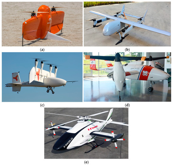
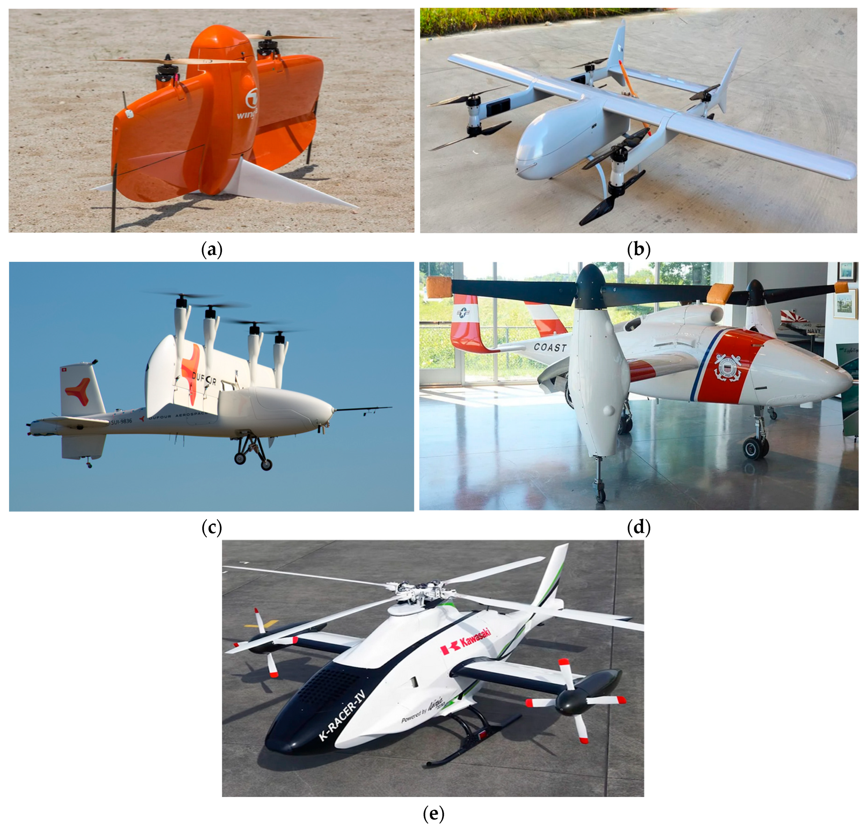
The UAV sector is currently one of the most significant and promising fields within the aeronautical industry, due to the wide range of applications and the advanced operational capabilities offered by these aircraft [1,2,3,4,5]. From a technological standpoint, numerous design solutions are available, differing in both aerodynamic layout and propulsion configuration, depending on specific operational requirements [6]. In recent years, increasing attention has been devoted to the development of hybrid architectures, as they combine the advantages of internal combustion and electric technologies, overcoming the limitations associated with the exclusive use of a single type of propulsion [7,8,9]. Propulsion and energy management therefore play a key role in UAV design, as they strongly influence autonomy, mobility performance and achievable mission profiles. For instance, multirotor UAVs provide excellent hovering and VTOL (Vertical Take-Off and Landing) capabilities, but they are inherently limited in long-range operations due to reduced endurance and aerodynamic efficiency. Fixed-wing UAVs, on the other hand, exhibit high aerodynamic efficiency and can cover long distances at relatively high cruise speeds but lack VTOL and sustained hovering capabilities [10]. For these reasons, as show Figure 1, a wide range of propulsion layouts has been proposed to combine the advantages of fixed-wing and rotary-wing aircraft, enabling high aerodynamic efficiency, extended range and endurance, while preserving hovering and VTOL capabilities.
Figure 1.
Different propulsion layout: (a) Tail-sitter; (b) Dual system; (c) Tilt-wing; (d) Tilt rotor; (e) Compound helicopter.
A tail-sitter UAV is designed to take off and land on its tail and, during the transition maneuvers, reorients its body by approximately 90°, resulting in a change of the vehicle coordinate system [11] between different flight phases. UAVs with dual-system configuration employ two independent propulsion systems. One dedicated to vertical flight, usually based on a multirotor-like layout, and a second optimized for forward flight, adopting a fixed-wing configuration with one or more tractor or pusher propellers [12]. Tilt rotor UAV has propulsions attached to the wingtips. For rotors it is possible to rotate from vertical to horizontal position depending on the flight phase [13]. In the case of tilt-wing UAV, the propulsions are permanently attached to the wing which can rotate [14]. During hovering, the rotor and tilt wing propulsions are in a vertical position and produce thrust necessary to balance aircraft weight. On the other hand, in forward flight propulsions are in a horizontal position and generate thrust while the wing produces lift. In both tilt configurations, control during forward flight is similar to that in a classical fixed wing UAV. In hover, control is performed by changing the direction and the amount of thrust on rotors [15]. Finally, compound helicopter UAVs present a configuration similar to that of a conventional helicopter, to which fixed wings and an auxiliary propulsion system are added. A conventional helicopter relies solely on the main rotor to generate both lift and thrust; however, as forward speed increases, asymmetric flow conditions adversely affect the lift and thrust capabilities of the rotor. Reducing the lift requirement of the main rotor removing the need for the rotor to provide propulsive force can significantly alleviate these limitations. This can be achieved by compounding the aircraft through the addition of wings (lift compounding) and auxiliary propulsion system (thrust compounding). When partially offloaded, the main rotor can be operated at a reduced rotational speed, thereby maintaining low rotor drag at high forward velocities. Lift compounding consists of integrating a fixed wing into the airframe to generate lift during forward flight, allowing the wing to support the aircraft weight and thus unload the main rotor. Since a wing is generally more aerodynamically efficient than a rotor in producing lift as air speed increases, lift compounding improves the overall aerodynamic efficiency of the aircraft. Thrust compounding consists of adding a dedicated propulsion system to generate thrust during forward flight, allowing higher forward speeds to be achieved [16]. Finally, the reaction torque generated by the main rotor can be balanced either by the same propulsors used for forward flight or by a tail rotor, as in conventional helicopters. As part of the VERTIGO project, the authors investigated and supported the development of an innovative hybrid UAV based on a compound helicopter configuration, whose preliminary design specifications are summarized in Table 1.
Table 1.
Preliminary design specifications of the VERTIGO UAV.
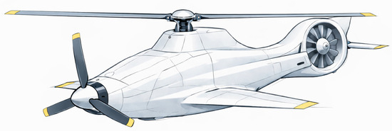
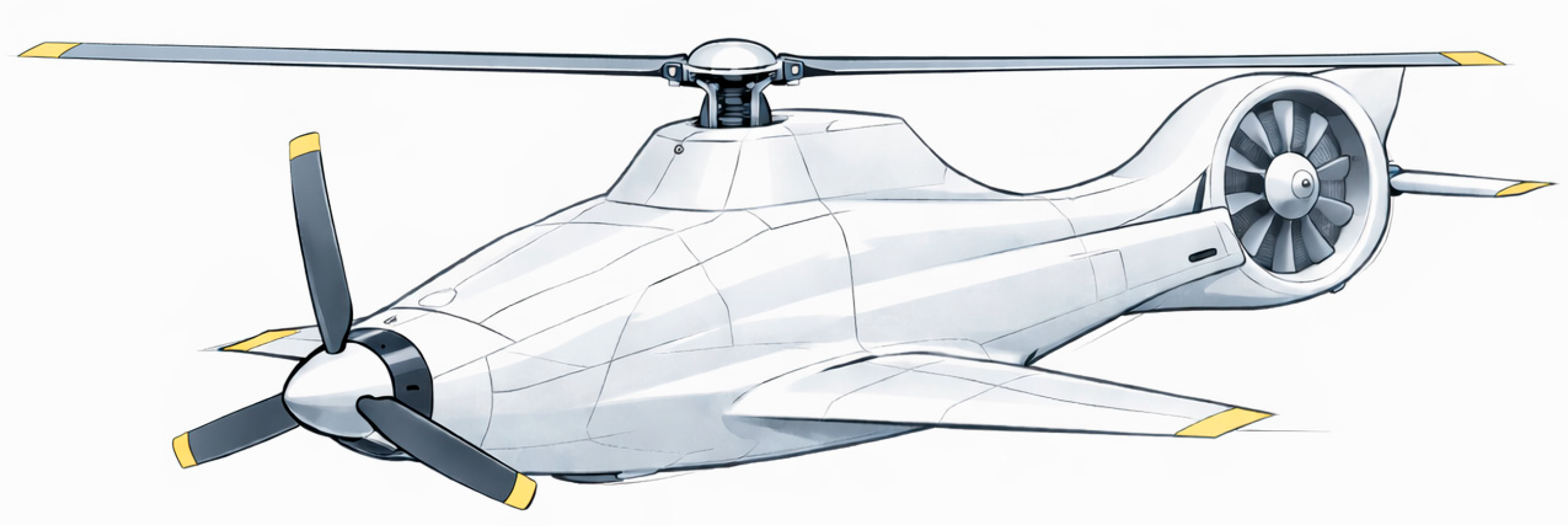
Furthermore, the aircraft must be capable of fulfilling the mission profiles described in Table 2. As shown, the UAV must operate under different flight conditions. Mission 2 and Mission 3 involve prolonged operation either in forward flight at cruise speed or in hovering, whereas Mission 1 requires multiple transitions between these flight conditions. This requirement for operational versatility led the authors to adopt a propulsion layout based on a compound helicopter configuration described in Figure 2.
Table 2.
Mission Profiles.
Figure 2.
Conceptual representation of the proposed propulsion layout.
2. Hybrid Propulsion System
The proposed propulsion layout is illustrated in Figure 2. As shown, the UAV is equipped with three main actuators: a nose-mounted tractor propeller, a main rotor and a Fenestron tail rotor.
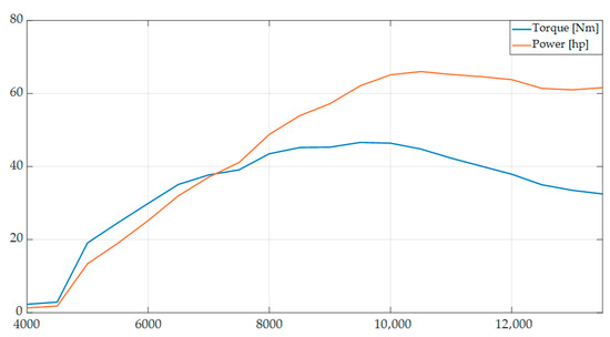
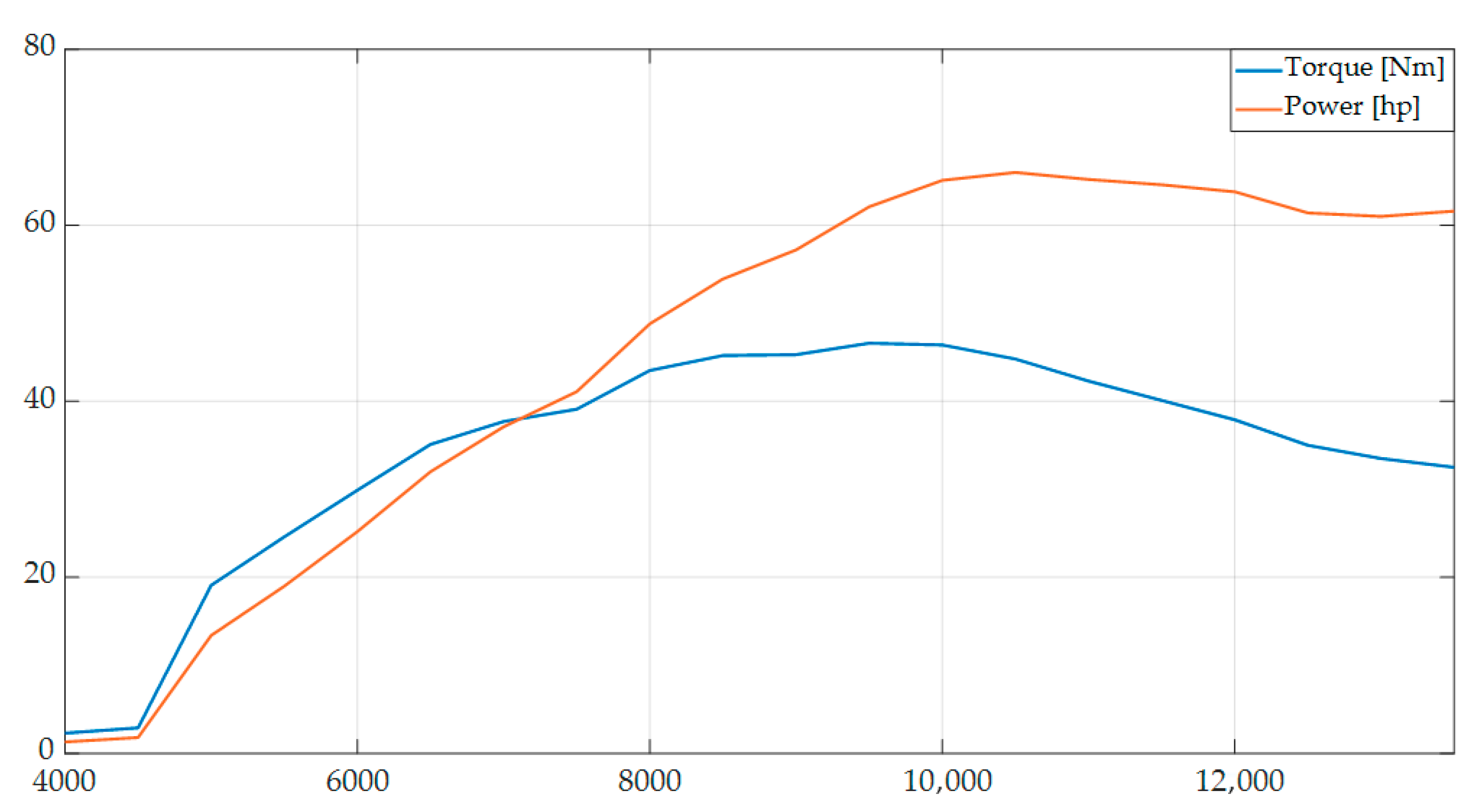
During forward flight, the aircraft behaves as a fixed-wing UAV, with the wings providing lift and the nose-mounted propeller generating the required thrust. In vertical flight, the vehicle operates the main rotor and the Fenestron tail rotor in a manner equivalent to that of a conventional helicopter. To manage power distribution across the different flight phases and meet the mission requirements, the adoption of a hybrid propulsion system was necessary. The proposed hybrid architecture is a mixed series-parallel configuration employing a Wankel engine as the primary power source. This specific architecture was selected following an extensive trade-off analysis of various hybrid configurations. It represents an optimal balance between energy efficiency, system reliability, and industrial manufacturability, meeting the stringent weight and complexity constraints required for this class of UAV. Furthermore, the decision to employ a Wankel engine is motivated by the high power-to-weight ratio achievable with this type of engine, as confirmed by market analyses and the literature [17]. Indeed, the selected engine is a commercial Wankel [18] delivering approximately 46 kW of power at weight of around 18 kg, further confirming its high power-to-weight ratio. The associated power and torque curves are shown in Figure 3.
Figure 3.
ICE’s performances.
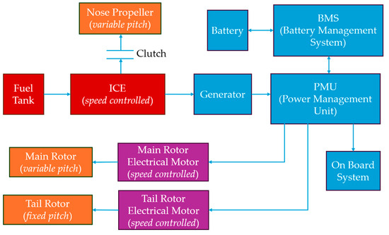
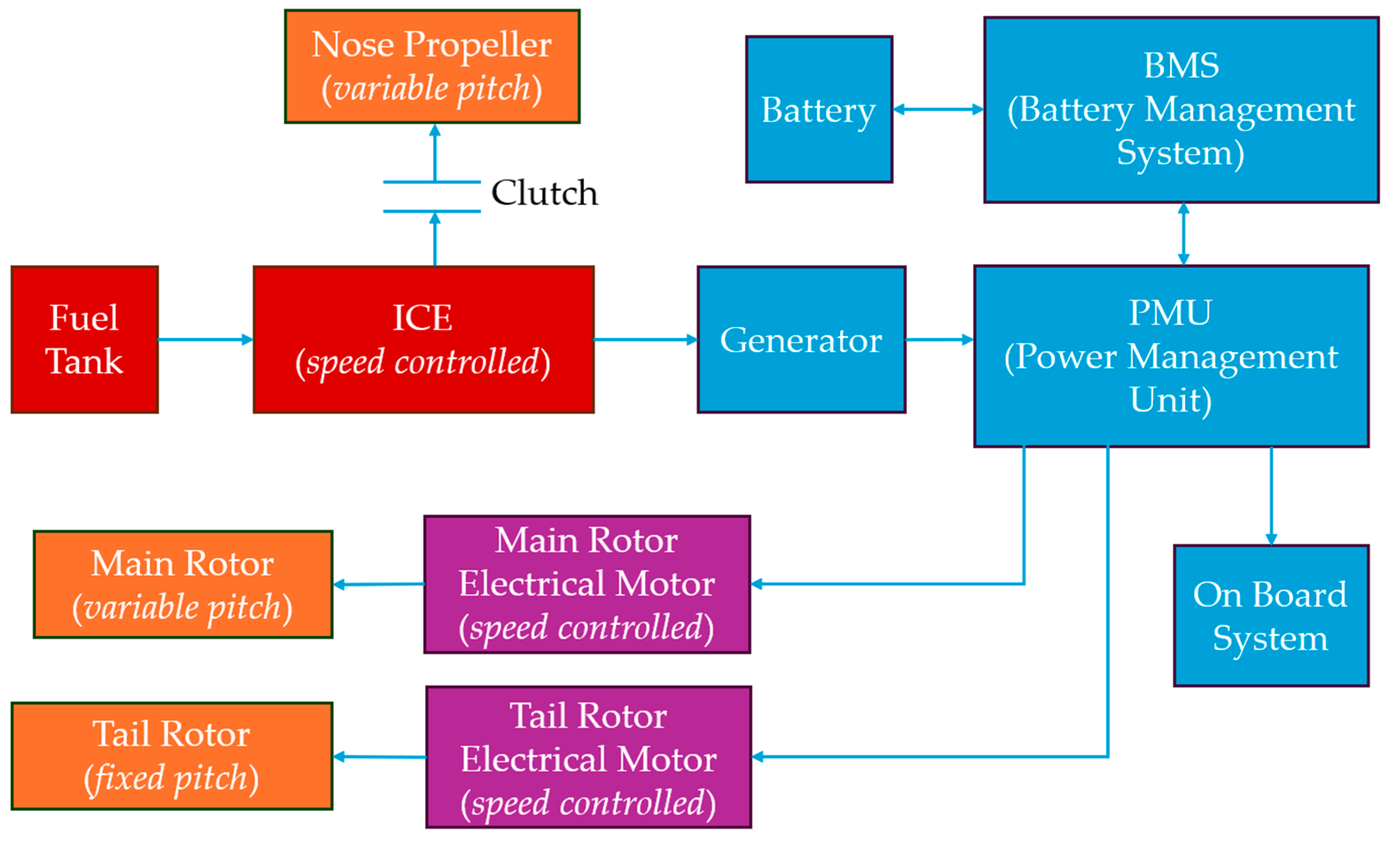
As illustrated in Figure 4, the Wankel engine (ICE) is directly coupled to the nose-mounted propeller through a clutch, as in a parallel hybrid layout. This configuration allows the transmission efficiency to be optimized during forward flight. To avoid the need to continuously adapt the engine rotational speed to the load demand, a variable pitch propeller has been adopted for the nose-mounted propeller. In this way, the internal combustion engine can operate within a high efficiency speed range, while the required thrust is regulated through variations in the propeller pitch. The same primary power source also drives a generator, which provides the electrical power required for battery recharging and for supplying the onboard systems, as well as the electric motors used to drive the main rotor and the tail rotor, thereby implementing the series branch of hybrid architecture. Power flows are managed by a Power Management Unit (PMU), which also enables the integration of battery power with generator power, improving the overall regulation dynamics.
Figure 4.
Proposed series-parallel architecture.
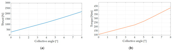
Regarding the other propulsion units, the tail rotor adopts a fixed pitch propeller, with thrust controlled by varying the rotational speed through a radial-flux BLDC electric motor. The main rotor is equipped with a collective pitch mechanism, allowing the required thrust to be adjusted through variation of the collective pitch angle. In addition, a large diameter rotor was selected to improve lift generation efficiency. To manage the high torque required by the main rotor, shown in Figure 5, an axial-flux electric motor coupled with a two-stage epicyclic gearbox featuring a 1:8 reduction ratio was adopted. This solution was selected as it minimizes the overall system weight compared with a commercial direct-drive configuration.
Figure 5.
(a) Main rotor thrust at 600 rpm as a function of the collective pitch angle; (b) Main rotor torque at 600 rpm as a function of the collective pitch angle.
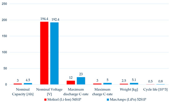
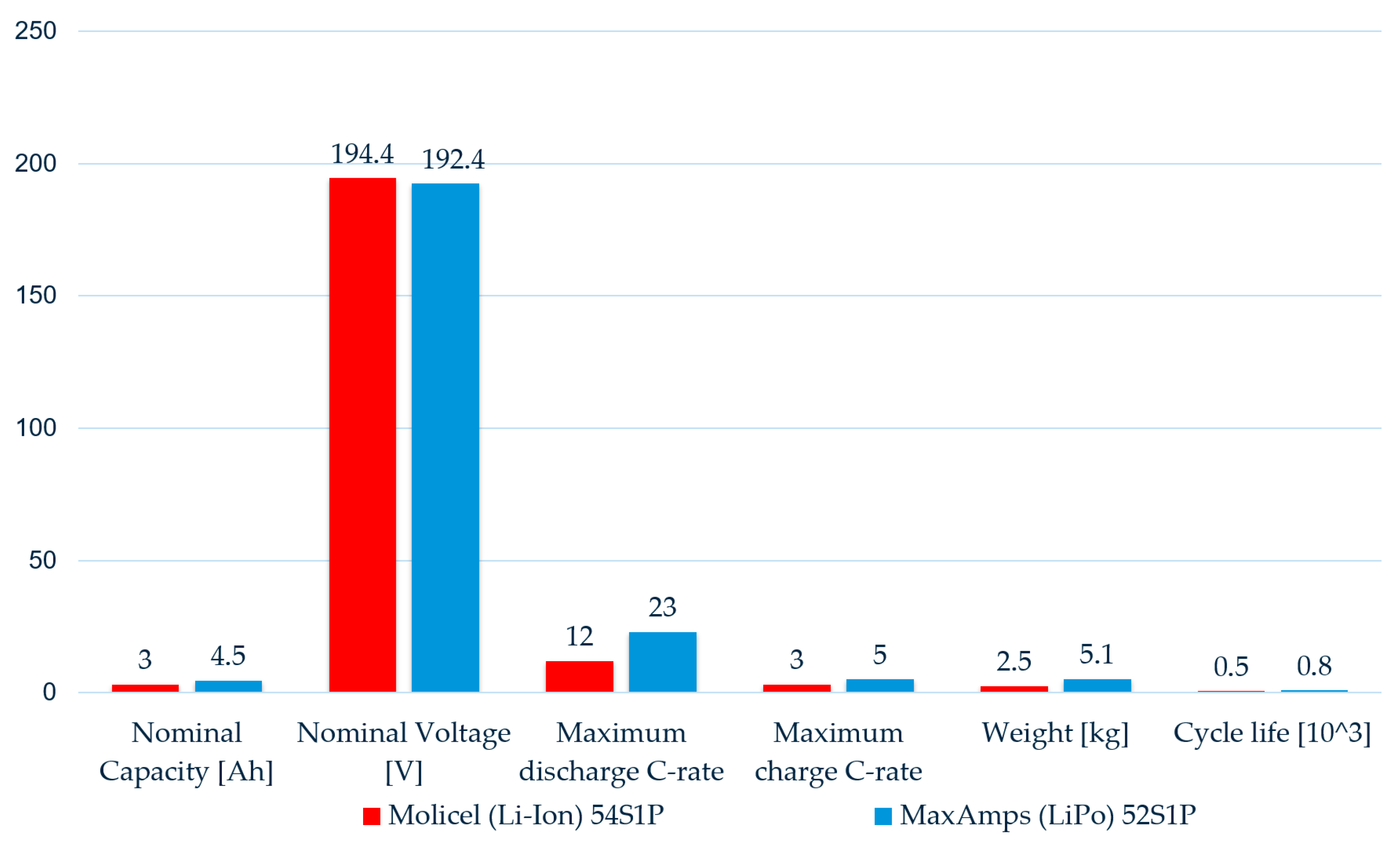
Finally, two battery cell technologies commonly employed in this type of application were considered and compared: LiPo [19,20] and Li-Ion [21]. The comparison, based on the assembled battery pack required to meet the design requirements, is reported in Figure 6. Lithium-ion (Li-Ion) cells were chosen over LiPo due to their lower mass, offering improved energy density for the UAV battery pack.
Figure 6.
Comparison of the designed battery pack technologies.
Table 3 summarizes the hybrid system’s principal component weights.
Table 3.
Hybrid system’s principal component weights.
3. Digital Twin of the Propulsion System
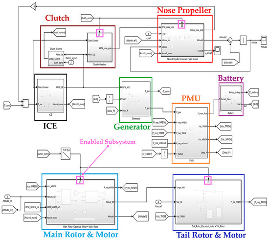
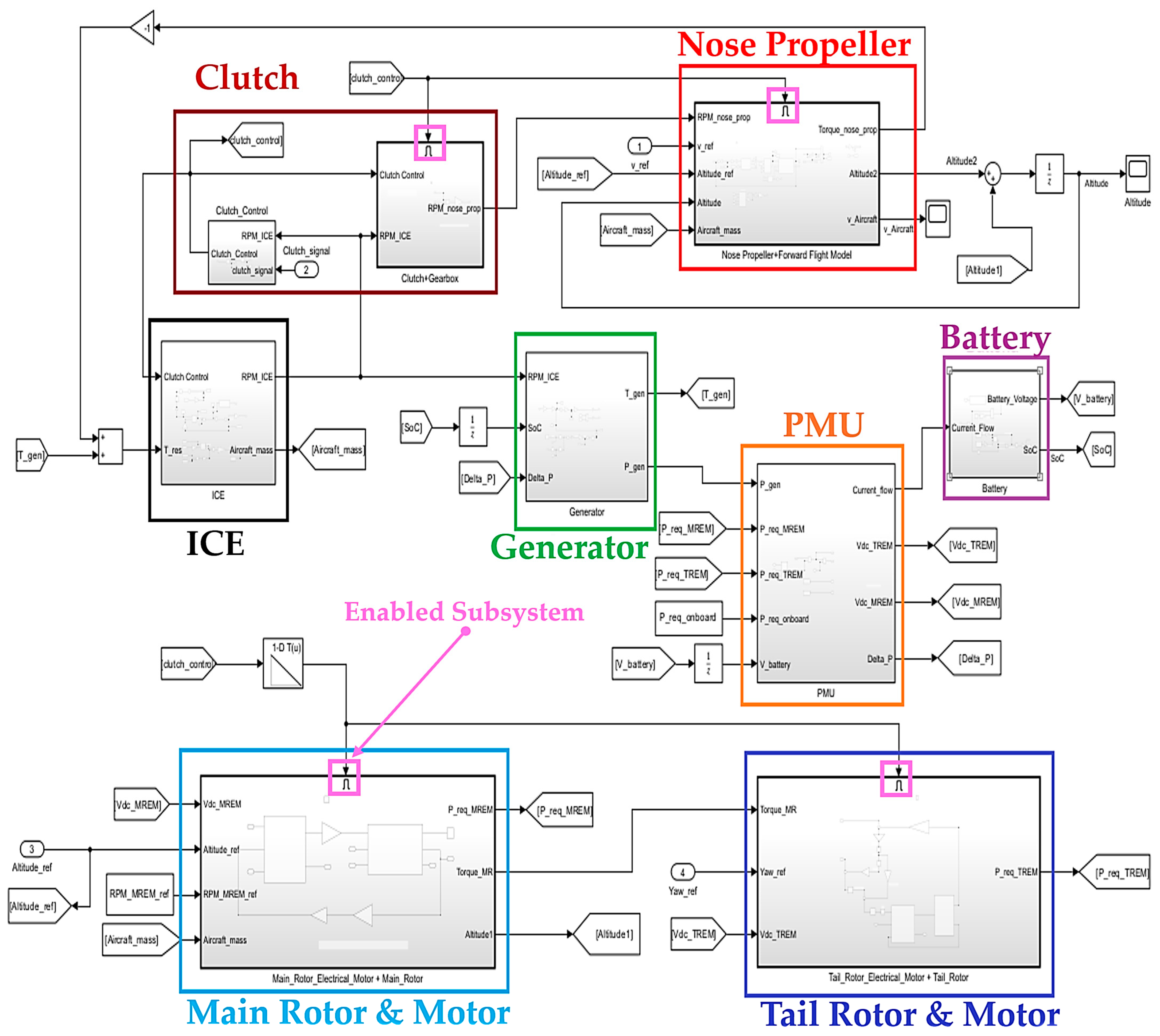
The digital twin of the propulsion system, illustrated in Figure 7, was constructed following the layout of the proposed hybrid architecture (Figure 4) and implemented using MATLAB-Simulink R2024b™.
Figure 7.
Digital Twin of the propulsion system.
Furthermore, the subsystems were implemented using enable signals, allowing their selective activation according to the UAV’s operational modes. This approach reduces computational load, increases simulation execution speed and facilitates implementation on embedded or real-time systems. Reference signals were defined to reproduce the desired mission profiles and drive the propulsion system throughout the simulations, enforcing target conditions for aircraft speed, altitude, yaw angle and UAV’s operational mode. To track the reference signals, multi-level control schemes were implemented, typically based on PID regulators arranged in a cascade configuration. In this structure, the outer loop measures the variable to be controlled, compares it with the desired setpoint, and generates a control signal that serves as the reference for the inner loop. The inner loop then compares this reference with the corresponding intermediate variable and regulates the actuator command accordingly. Such cascade control architectures improve system stability and enable faster dynamic response [22,23]. Two different operating modes were considered for the UAV: fixed-wing mode and VTOL mode.
3.1. Fixed-Wing Mode
During the fixed-wing mode, the UAV behaves as a conventional aircraft. The clutch is engaged and the block associated with the nose-mounted propeller (Nose Propeller in Figure 7) is executed, while the blocks related to the two rotors remain inactive. The longitudinal dynamics of the aircraft are described by the following equation:
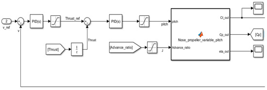
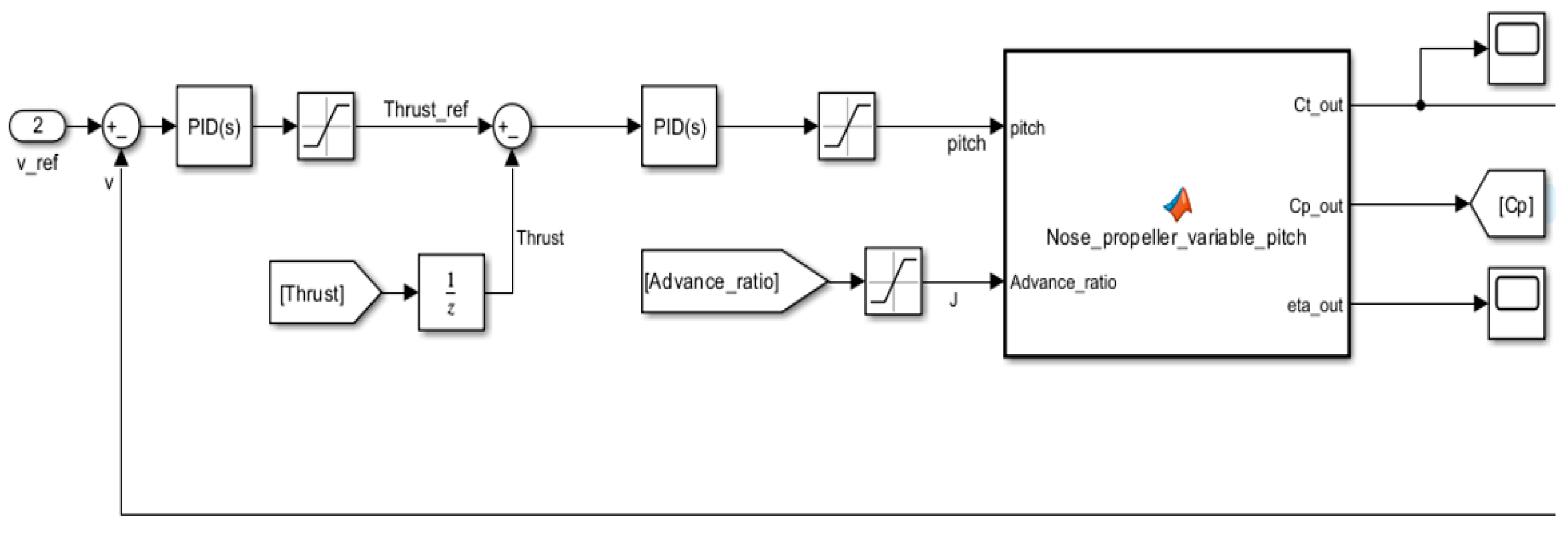
where is the longitudinal speed; is the nose propeller thrust; is the drag; and are the aircraft mass and weight; and denotes the rate of climb. In this operating mode, which is employed during cruise, ascent and descent phases in forward flight, the internal combustion engine operates at a constant rotational speed; consequently, the nose-mounted propeller also rotates at a constant speed. To track the required speed reference, the propeller thrust is regulated by varying the propeller pitch, as illustrated in Figure 8.
Figure 8.
Pitch control for reference speed tracking.
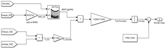
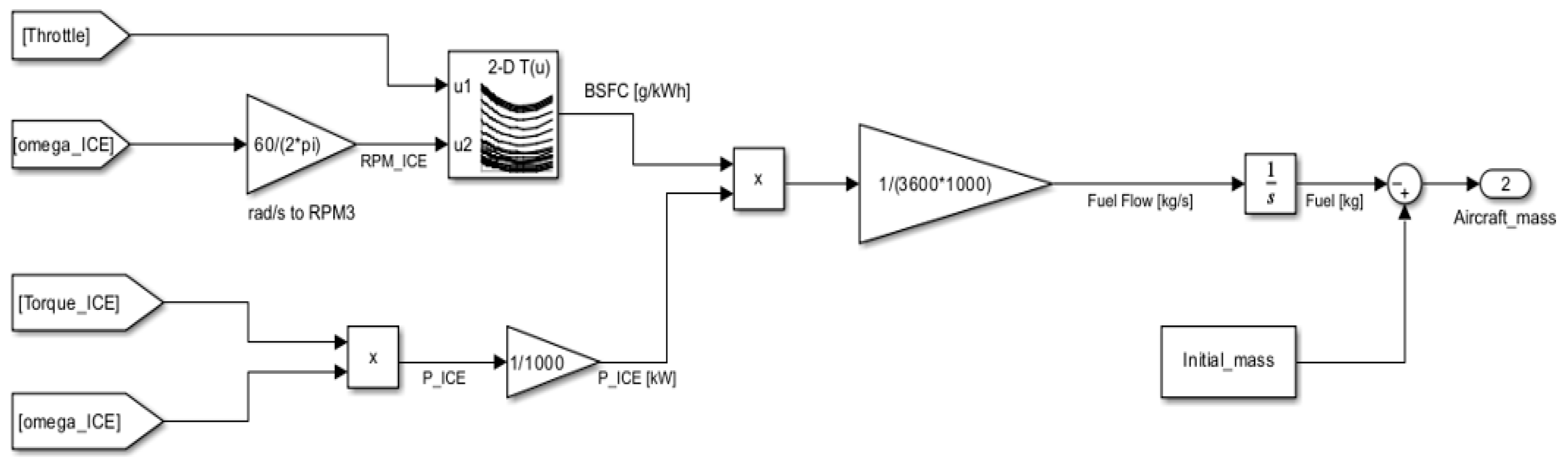
The propeller thrust and torque were evaluated using the advance coefficient J, the thrust coefficient and the power coefficient [24]. In particular, the trends of and were determined as functions of the advance coefficient J and the propeller pitch, allowing the corresponding thrust and torque to be computed. The resulting torque is finally rejected by the Wankel engine as an external disturbance by means of the engine speed control. Finally, fuel consumption was evaluated to determine the aircraft mass throughout the simulation. The fuel flow was computed considering the engine power and the brake specific consumption (BSFC), obtained from a 2-D lookup table as a function of throttle and rpm, and then converted into a mass flow rate. The cumulative fuel mass was integrated over time and subtracted from the initial aircraft mass to obtain its evolution during simulation, as illustrated in Figure 9.
Figure 9.
Fuel flow calculation and mass evolution during simulation.
3.2. VTOL Mode
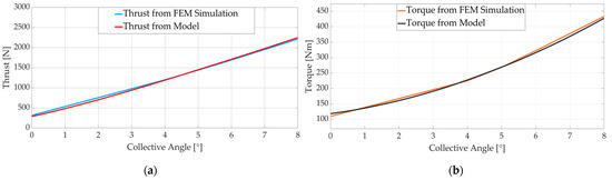
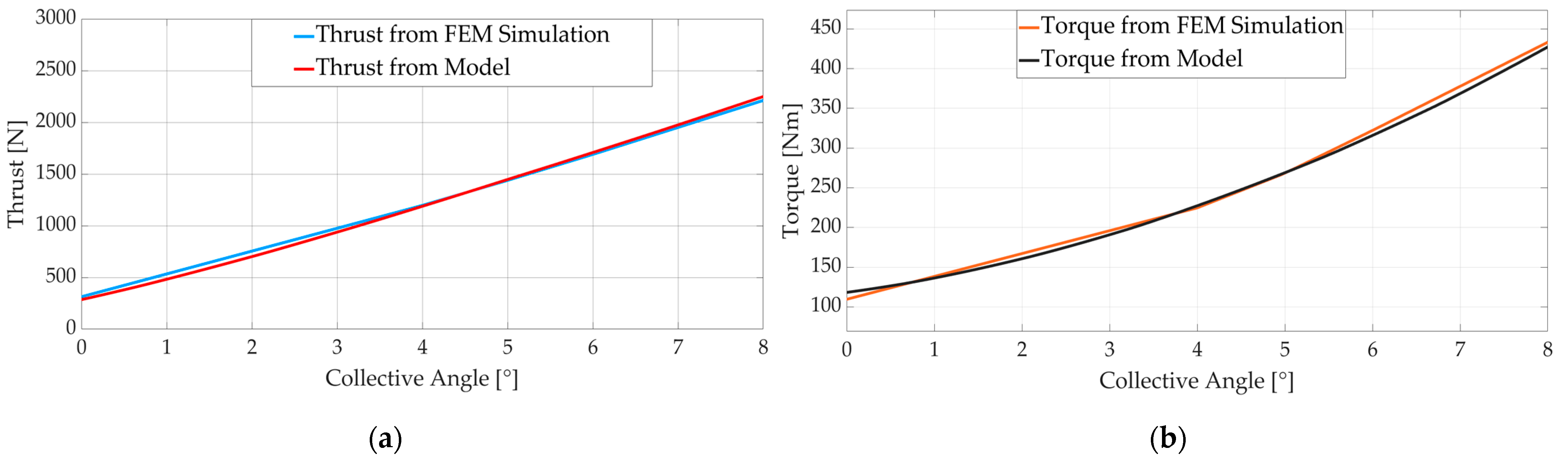
In VTOL mode, the UAV behaves like a helicopter. The blocks associated with the two rotors are active, while the block corresponding to the nose-mounted propeller is deactivated, as the clutch is disengaged. This mode is employed for takeoff and landing phases, as well as for hovering during target monitoring. The main rotor model was implemented using a Simulink-Simscape R2024b™ library [25], employing a Blade Element Momentum Theory (BEMT) approach [26] to compute the thrust and torque generated by the rotor as functions of rotational speed, advance speed and collective pitch angle. Once calibrated, the model results were compared with reference data obtained from the FEM analysis shown in Figure 5, demonstrating good agreement, as illustrated in Figure 10.
Figure 10.
Comparison between BEMT model and FEM results for the main rotor in hovering condition at 600 rpm: (a) Thrust; (b) Torque.
The proposed model therefore enables the simulation of the different vertical flight phases by controlling the rotor thrust through variations of the collective pitch angle, while maintaining a constant rotor rotational speed. Moreover, the same model can also be used to represent the autorotation operating condition of the aircraft, typical of gyrodynes, which may be particularly useful in the case of an emergency landing following a critical failure. The tail rotor is instead responsible for yaw control. To compensate for the torque generated by the main rotor, or to achieve a desired yaw angle, the tail rotor thrust is regulated according to (2) by varying the rotational speed of its electric motor, as the propeller has a fixed pitch. The resulting yawning acceleration is given by:
where is the yaw angle, is the distance between the UAV center of mass and the tail rotor, is the torque generated by the main rotor and is the UAV rotational inertia. The electric motors of the main and tail rotors are represented using a simplified model of a brushless DC (BLDC) motor, defined by the following equations:
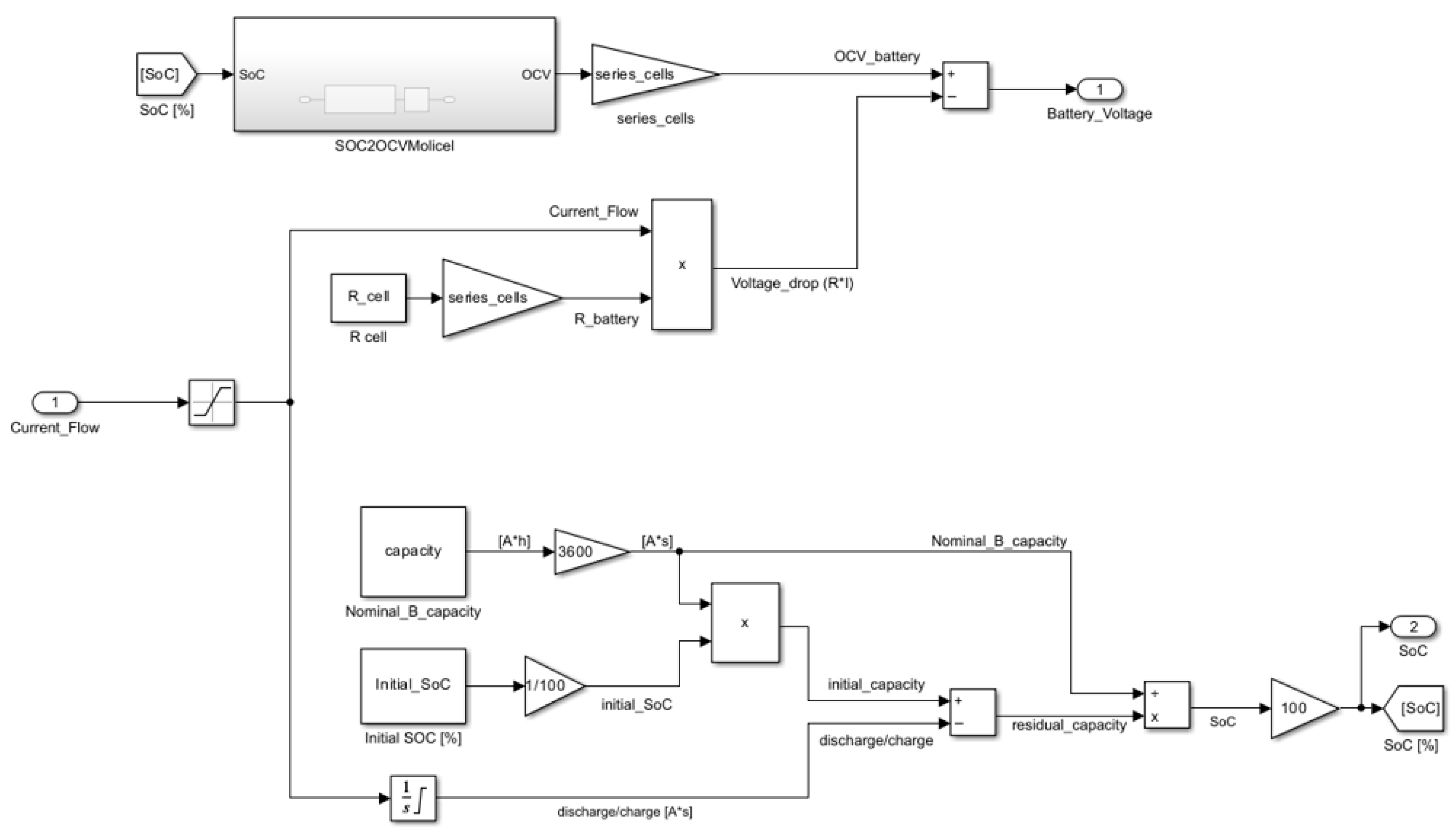
where and represent the applied voltage and current; and are the motor inductance and resistance; , and are the coefficients of back EMF, torque, and viscous friction, respectively; and , , and are the total shaft rotational inertia, angular speed and load torque. This modeling approach allows all relevant motor variables to be determined and the rotational speed to be controlled through a PWM signal that regulates the applied voltage. Finally, the power demanded by the motors is drawn from the battery via the Power Management Unit (PMU). The battery was modeled starting from a basic electric cell representation [27], accounting for the number of the connected cells. The battery model is defined by (5), which includes the dependence of the open circuit voltage (OCV) on the state of charge (SoC).
where , and denote the battery voltage, the equivalent internal resistance and the battery current, respectively. The state of charge is evaluated according to the following equation:
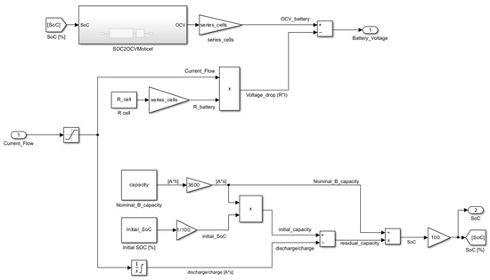
where is the initial battery capacity, is the battery current (positive during discharge), and is the nominal battery capacity. Once the state of charge is determined, the complete battery model can be implemented, as illustrated in Figure 11.
Figure 11.
Battery model.
Finally, the generator is employed to maintain the batteries at a constant State of Charge (SoC). The control system regulates the generator torque as a function of the battery SoC and the instantaneous power demand. Specifically, the torque reference is determined by an SoC regulation loop designed to reject load disturbances by using the current SoC estimate and its derivative relative to the expected load as feedback signals. This control strategy ensures that the SoC returns to its reference value while accounting for the generator’s operational limits through predefined torque maps. As a result, an increase in the power demanded by the motors leads to a rise in the generator torque, which is compensated by the internal combustion engine to stabilize its rotational speed.
4. Simulation Results
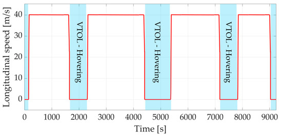
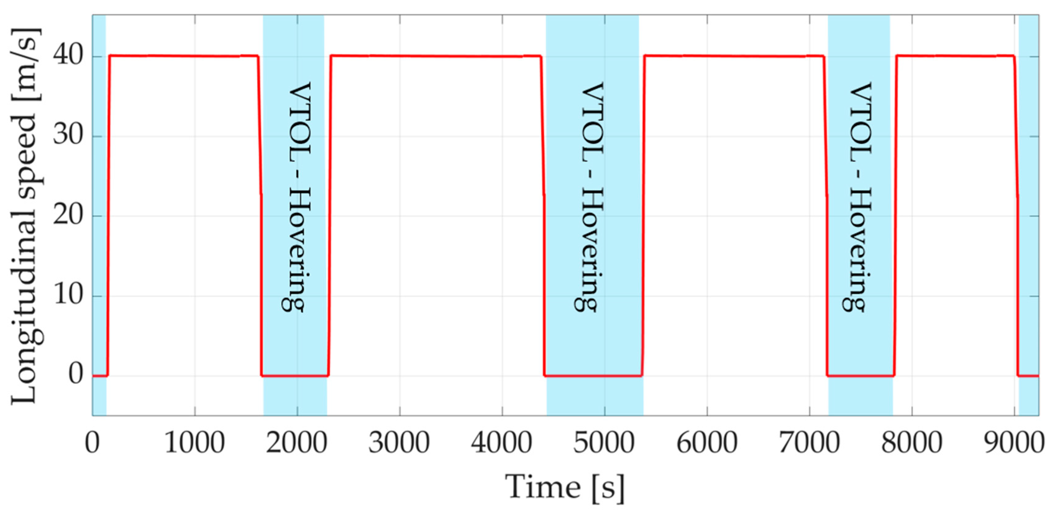
The system behavior under different operating conditions was assessed by implementing the reference signals and simulating the three mission scenarios. The following section presents selected simulation results for Mission 1—Multi Stop Over, considered the most representative scenario since it involves the largest number of transitions between the two flight modes and reflects the primary operational use of the UAV. The mission consists of five vertical flight phases alternating with four forward flight phases. As shown in Figure 12, the UAV reaches a longitudinal speed of 40 m/s during forward flight phases, while it remains zero during hovering and during vertical take-off and landing, as required by the imposed reference signal. Deviations during forward flight remain below 0.4% and are mainly attributable to variations in the rate of climb (RoC).
Figure 12.
Simulation of mission 1—Longitudinal speed.
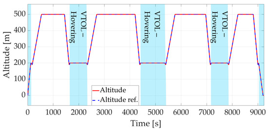
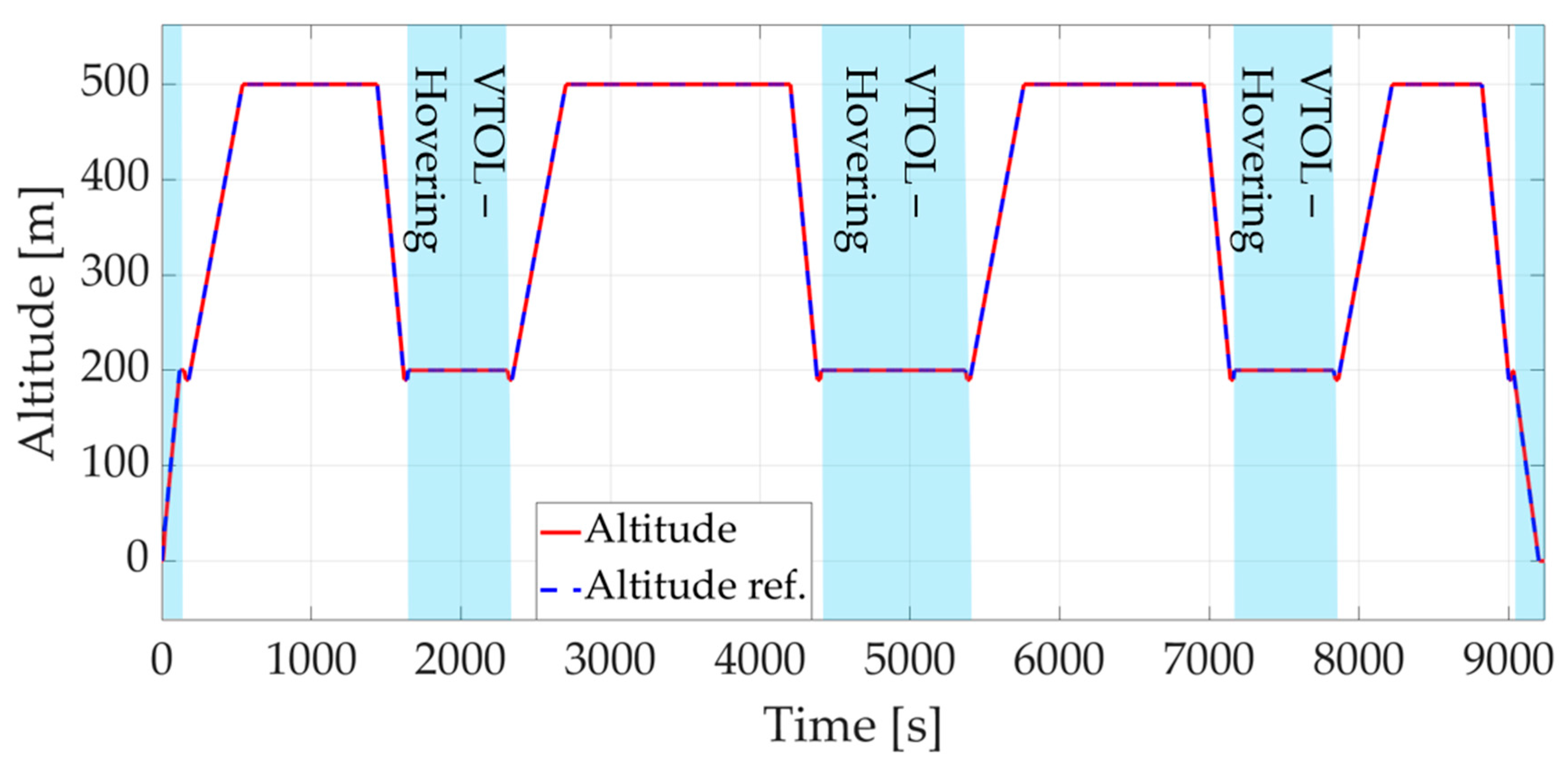
The altitude profile and its reference signal are reported in Figure 13, showing that the UAV accurately follows the imposed altitude profile throughout the mission.
Figure 13.
Simulation of mission 1—Altitude.
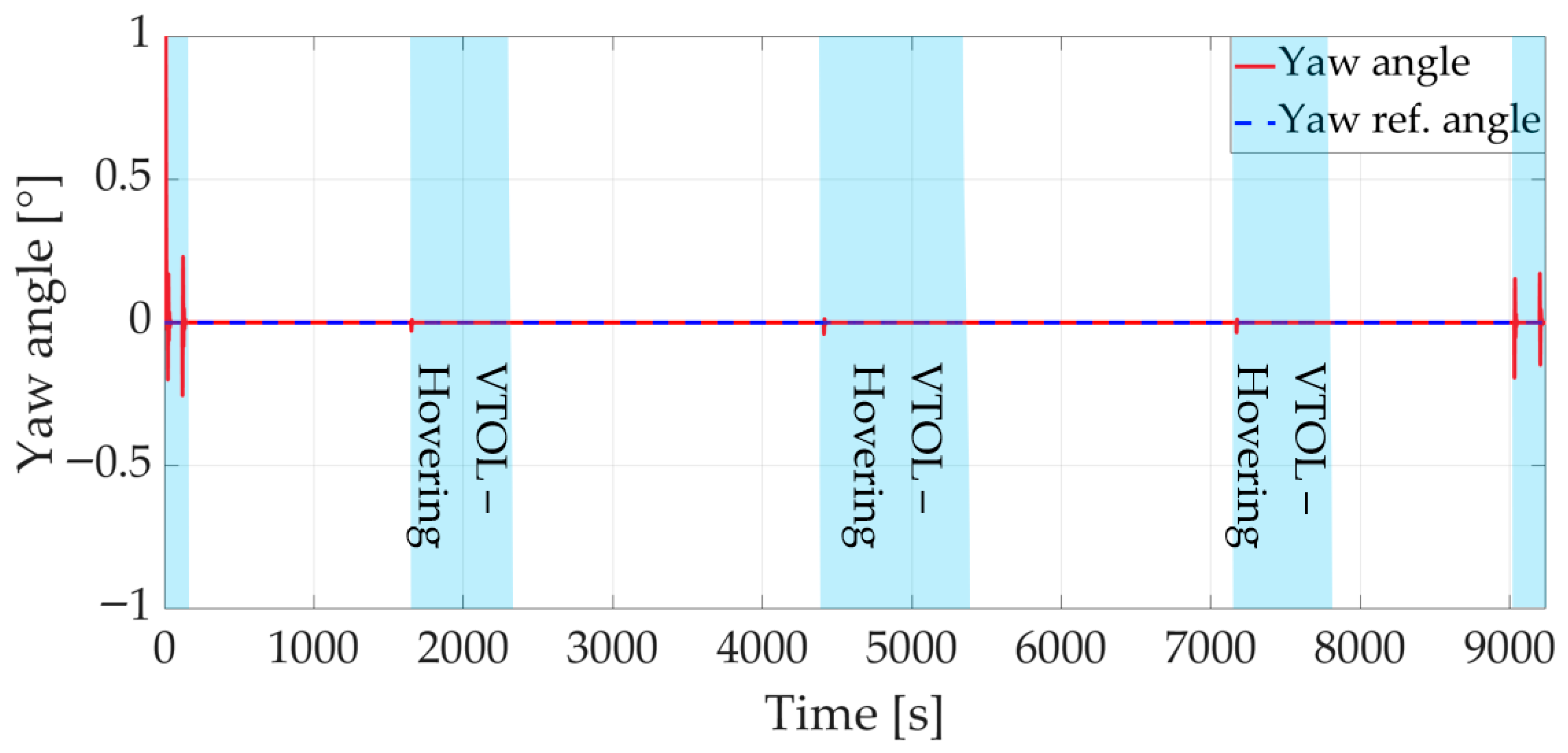
Figure 14 shows the yaw angle response and the corresponding reference signal, which is set to zero in order to achieve yaw stabilization. An initial peak can be observed during the initial take-off phase. This deviation is mainly due to the rapid increase in thrust generated by the main rotor to satisfy the imposed altitude reference, which results in a corresponding increase in the associated torque. The observed error is therefore attributable to the delay with which the tail rotor compensates for the torque variation produced by the main rotor, due to the dynamics of the control system. The maximum deviation remains acceptable given its limited magnitude and the fact that subsequent variations from the reference are significantly smaller.
Figure 14.
Simulation of mission 1—Yaw angle.
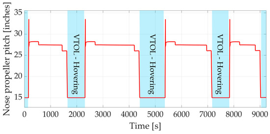
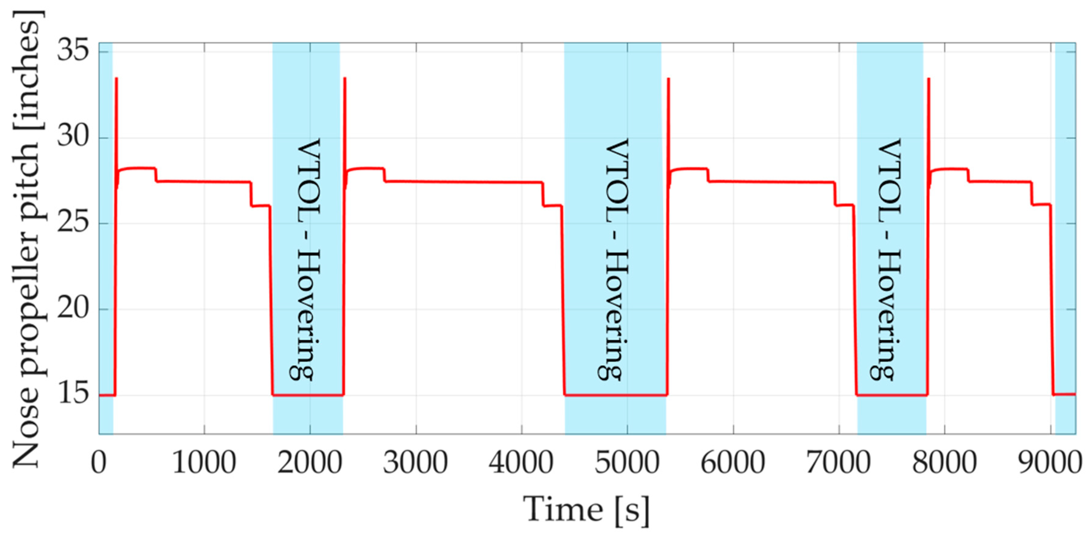
To control the UAV speed, the nose-mounted propeller pitch is progressively adjusted, as shown in Figure 15. During the transition from vertical to forward flight, the pitch is gradually increased to accelerate the UAV. Once in forward flight, it stabilizes at three distinct values corresponding to the ascent, cruise and descent phases. During the transition from forward to vertical flight, the pitch is gradually reduced to its minimum value of 15 inches, which is retained throughout vertical flight; the propeller, however, is mechanically disengaged via the clutch and does not contribute to thrust in this phase.
Figure 15.
Simulation of mission 1—Nose-mounted propeller pitch.
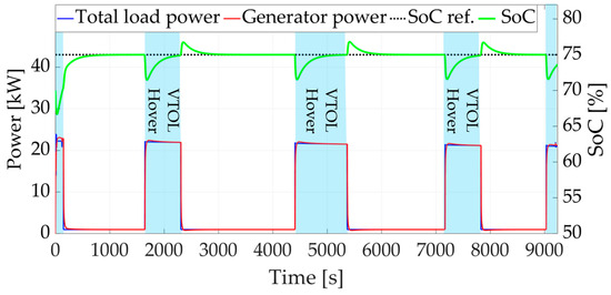
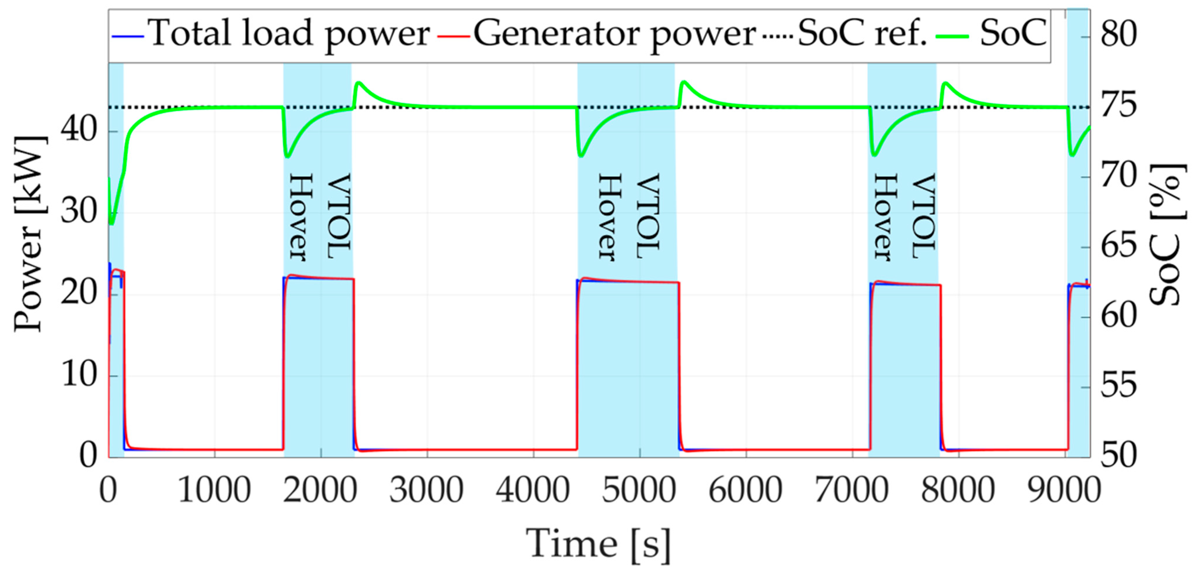
The total electrical power demand from the loads, the power supplied by the generator (reported in absolute value), and the battery state of charge (SoC) are illustrated in Figure 16.
Figure 16.
Simulation of mission 1—Total load power, generator power and battery SoC.
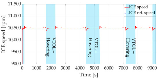
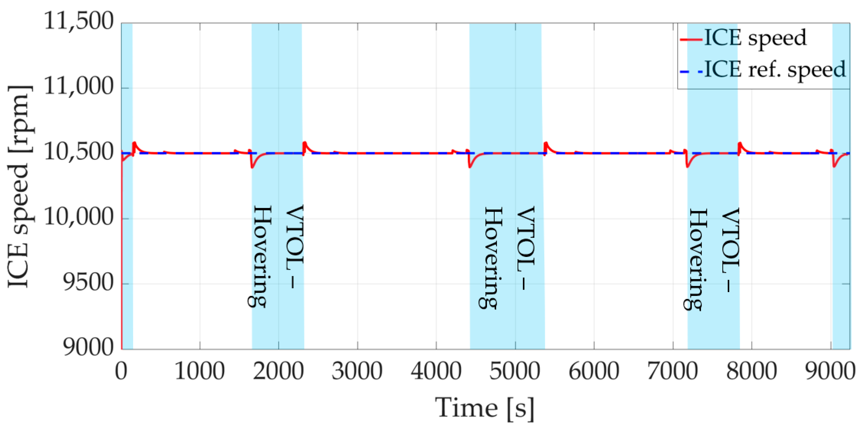
The total electrical power demanded by the loads reaches its maximum during the initial take-off phase, when the system accelerates to the required vertical speed. In this condition, the main rotor must produce thrust greater than that required to balance the UAV weight, resulting in an increased power demand. Once the desired vertical speed is reached, the power decreases and stabilizes at values close to those corresponding to hovering, which are necessary to maintain a constant vertical velocity. During forward flight, the electrical power demanded by the loads corresponds only to that required by the onboard systems, since the nose-mounted propeller is powered directly by the internal combustion engine. During successive hovering phases, the required power gradually decreases, due to the progressive reduction in UAV mass caused by fuel consumption. The electrical power supplied by the generator exhibits a trend similar to the total demand, with reduced peak values. Rapid power variations associated with transient flight phases are mainly compensated by the battery, which supplies or absorbs power to smooth these fluctuations and to allow the generator to operate under more regular conditions. When the battery is partially discharged and operating conditions permit, the generator provides slightly more power than that required by the loads in order to recharge the energy storage system. The battery SoC exhibits different trends depending on whether the battery is delivering or absorbing power, due to the different C-rates associated with the charging and discharging phases. If the SoC exceeds the reference value after a transient, the excess energy is gradually absorbed by the onboard loads, restoring the target SoC. The internal combustion engine (ICE) is regulated to operate at a constant rotational speed, chosen at the point of maximum efficiency corresponding to minimum specific fuel consumption (SFC), to meet the required power demand. As shown in Figure 17, the engine accurately tracks the commanded speed, while residual oscillations arising from torque variations across the flight phases are actively rejected by the speed control system.
Figure 17.
Simulation of mission 1—Internal combustion engine speed.
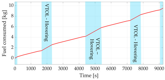
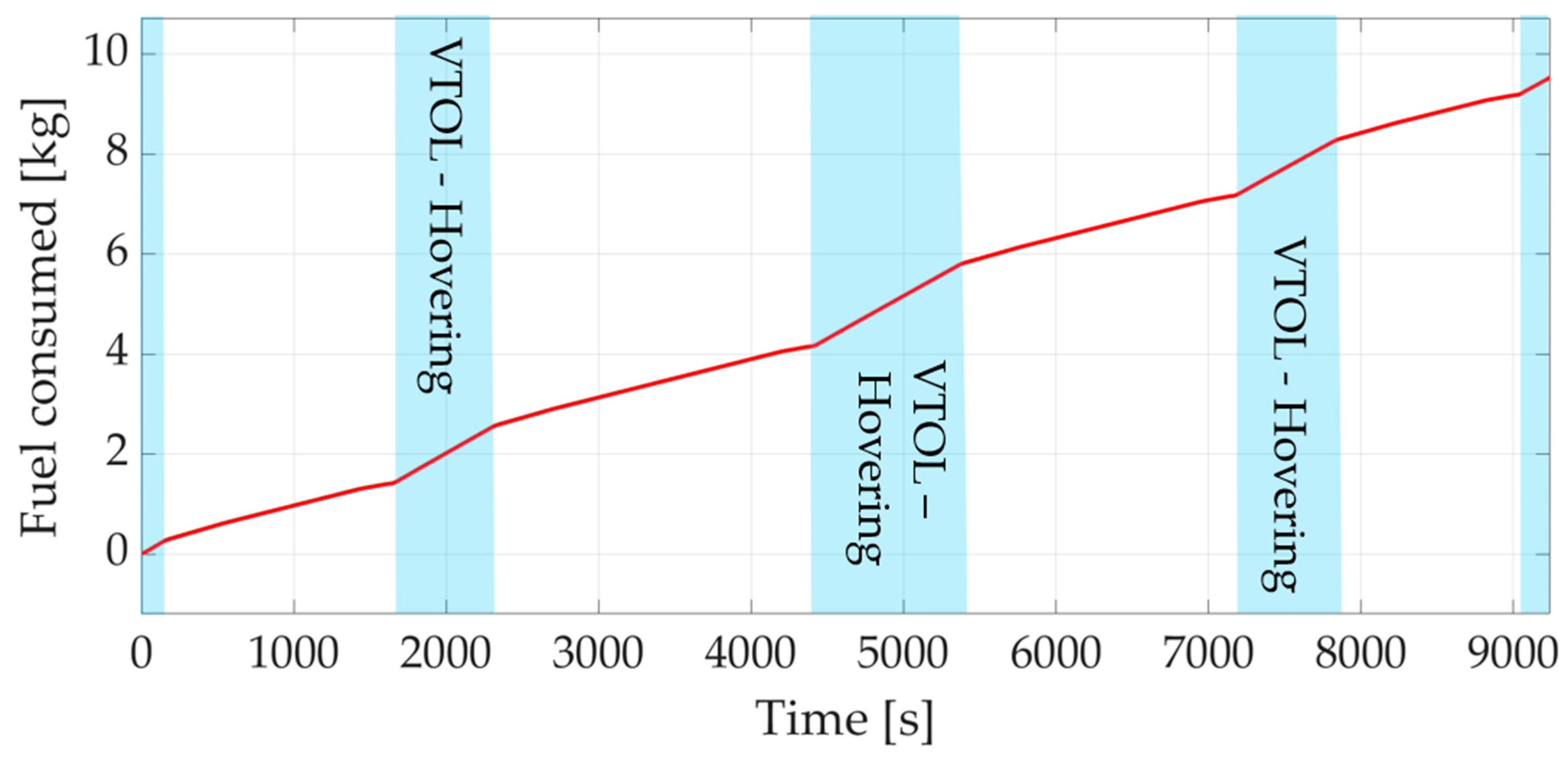
Finally, the evolution of fuel mass consumed throughout the entire mission is shown in Figure 18. The temporal evolution reveals that fuel consumption varies across the different flight phases. Notably, vertical flight phases are associated with higher fuel consumption compared to forward flight segments.
Figure 18.
Simulation of mission 1—Fuel Consumed.
5. Conclusions and Future Work
This work presents a hybrid propulsion system and its digital twin for an innovative autonomous compound helicopter designed for surveillance and monitoring missions. The obtained results confirm both the feasibility of the proposed propulsion architecture and the effectiveness of the developed model. Simulation results demonstrate that the model is able to reproduce the complex interactions among the different subsystems while accurately tracking the reference signals required to replicate the considered operational scenarios. In addition, the developed framework is highly configurable, enabling the rapid integration of additional components and allowing the analysis of system behavior under operating conditions different from those considered in this study. The current analysis focuses on configuration in which the propulsion system operates according to two main control modes. However, additional control strategies are currently under development, specifically targeting operating conditions where the main rotor operates in autorotation, similar to gyrodyne configurations. This built-in capability of the model represents a priority for future studies, providing a framework to investigate system behavior under fault or degraded conditions and to support the development of advanced safety-critical control strategies. Future activities will focus on enhancing Digital Twin’s fidelity by integrating flight-test data and accounting for non-modeled dynamics and environmental disturbances. This process will involve the use of advanced identification methods for dynamic loading and multisource uncertainties [28,29], which are essential for refining the structural and control response of the system under real-world operating conditions. Furthermore, subsequent research will include a comprehensive structural dynamic characterization to evaluate resonance risks. This will entail the calculation of natural frequencies and mode shapes for critical transmission components, utilizing advanced identification methods [30] to compare structural responses against operational harmonic frequencies, such as engine firing and blade passing frequencies, before proceeding with extensive experimental flight testing.
Author Contributions
Conceptualization, L.F. and G.M.; methodology, A.P. and L.P.; software, A.P.; validation, A.P. and L.P.; formal analysis, A.P. and L.P.; investigation, A.P.; resources, L.F. and G.M.; data curation, L.F. and G.M.; writing—original draft preparation, A.P.; writing—review and editing, L.P.; visualization, A.P.; supervision, L.P. and G.M.; project administration, G.M.; funding acquisition, L.P. and G.M. All authors have read and agreed to the published version of the manuscript.
Funding
This work is performed within the project Vertigo financed by Regione Toscana within the program PR FESR 2021-2027 OP1 OS1 Azione 1.1.4” Ricerca e sviluppo per le imprese anche in raggruppamento con organismi di ricerca”-Bando n.2 “Progetti di ricerca e sviluppo per le MPMI e Midcap”, D17H24003530009 DD- 25829.
Data Availability Statement
The raw data supporting the conclusions of this article will be made available by the authors on request.
Acknowledgments
The authors acknowledge the use of ChatGPT GPT-5.3 (OpenAI) for assisting in the generation of Figure 2, based on the authors’ specifications.
Conflicts of Interest
Authors Lorenzo Franchi and Giuseppe Mattei were employed by the company Sky Eye Systems S.r.l. The remaining authors declare that the research was conducted in the absence of any commercial or financial relationships that could be construed as a potential conflict of interest.
References
- Partheepan, S.; Sanati, F.; Hassan, J. Autonomous Unmanned Aerial Vehicles in Bushfire Management: Challenges and Opportunities. Drones 2023, 7, 47. [Google Scholar] [CrossRef] [Scilit]
- Muhmad Kamarulzaman, A.M.; Wan Mohd Jaafar, W.S.; Mohd Said, M.N.; Saad, S.N.M.; Mohan, M. UAV Implementations in Urban Planning and Related Sectors of Rapidly Developing Nations: A Review and Future Perspectives for Malaysia. Remote Sens. 2023, 15, 2845. [Google Scholar] [CrossRef] [Scilit]
- Mohsan, S.A.H.; Khan, M.A.; Noor, F.; Ullah, I.; Alsharif, M.H. Towards the Unmanned Aerial Vehicles (UAVs): A Comprehensive Review. Drones 2022, 6, 147. [Google Scholar] [CrossRef] [Scilit]
- Telli, K.; Kraa, O.; Himeur, Y.; Ouamane, A.; Boumehraz, M.; Atalla, S.; Mansoor, W. A Comprehensive Review of Recent Research Trends on Unmanned Aerial Vehicles (UAVs). Systems 2023, 11, 400. [Google Scholar] [CrossRef] [Scilit]
- Kostoglotov, A.A.; Galdin, E.V.; Pachin, A.R.; Mikhailov, G.G.; Napalkin, M.Y. Engineering Technologies for the Design of Unmanned Aerial Vehicles (Uavs) for Various Industries of the Agricultural Sector, Civil Engineering and Logistics. In Proceedings of the 4th International Conference on Technology Enhanced Learning in Higher Education (TELE) 2024, Lipetsk, Russia, 20–21 June 2024; pp. 192–197. [Google Scholar] [CrossRef] [Scilit]
- Amici, C.; Ceresoli, F.; Pasetti, M.; Saponi, M.; Tiboni, M.; Zanoni, S. Review of Propulsion System Design Strategies for Unmanned Aerial Vehicles. Appl. Sci. 2021, 11, 5209. [Google Scholar] [CrossRef] [Scilit]
- Benmoussa, A.; Gamboa, P.V. Effect of Control Parameters on Hybrid Electric Propulsion UAV Performance for Various Flight Conditions: Parametric Study. Appl. Mech. 2023, 4, 493–513. [Google Scholar] [CrossRef] [Scilit]
- Jarrah, K.; Alali, Y.; Lalko, A.; Rawashdeh, O. Flight Time Optimization and Modeling of a Hybrid Gasoline–Electric Multirotor Drone: An Experimental Study. Aerospace 2022, 9, 799. [Google Scholar] [CrossRef] [Scilit]
- Wachłaczenko, M.J. Hybrid Electric Propulsion System Digital Twin for Multi-Rotor Unmanned Aerial Vehicles. Sustainability 2025, 17, 4901. [Google Scholar] [CrossRef] [Scilit]
- Saeed, A.S.; Younes, A.B.; Cai, C.; Cai, G. A survey of hybrid Unmanned Aerial Vehicles. Prog. Aerosp. Sci. 2018, 98, 91–105. [Google Scholar] [CrossRef] [Scilit]
- Zhong, J.; Wang, C. Transition characteristics for a small tail-sitter unmanned aerial vehicle. Chin. J. Aeronaut. 2021, 34, 220–236. [Google Scholar] [CrossRef] [Scilit]
- Çakici, F.; Leblebicioǧlu, M.K. Control System Design of a Vertical Take-off and Landing Fixed-Wing UAV. IFAC-PapersOnLine 2016, 49, 267–272. [Google Scholar] [CrossRef] [Scilit]
- Liu, Z.; He, Y.; Yang, L.; Han, J. Control techniques of tilt rotor unmanned aerial vehicle systems: A review. Chin. J. Aeronaut. 2017, 30, 135–148. [Google Scholar] [CrossRef] [Scilit]
- Cetinsoy, E.; Dikyar, S.; Hancer, C.; Oner, K.T.; Sirimoglu, E.; Unel, M.; Aksit, M.F. Design and construction of a novel quad tilt-wing UAV. Mechatronics 2012, 22, 723–745. [Google Scholar] [CrossRef] [Scilit]
- Muchowski, J.; Szumski, M.; Krzysiak, A. Aerodynamic concept of the UAV in the gyrodyne configuration. Trans. Aerosp. Res. 2019, 2018, 49–66. [Google Scholar] [CrossRef] [Scilit]
- Yeo, H. Design and aeromechanics investigation of compound helicopters. Aerosp. Sci. Technol. 2019, 88, 158–173. [Google Scholar] [CrossRef] [Scilit]
- Donateo, T.; Cavalera, D. Increasing safety in ultralight aviation with a Wankel-based series/parallel hybrid electric power system. Machines 2022, 10, 486. [Google Scholar] [CrossRef] [Scilit]
- UAVHE RW1-300C. Tech. Doc. Available online: https://uavhe.eu/products/rw1-300c/ (accessed on 14 April 2026).
- MaxAmps LiPo Batteries. Datasheet of LiPo Batteries. Available online: https://maxamps.com/ (accessed on 14 April 2026).
- Agostini, F.; Fani, E.; Mattei, G.; Franchi, L.; Berzi, L.; Pugi, L. Simplified Thermal Identification and Modelling of Li-PO Batteries for Unmanned Aerial Vehicles. In Proceedings of the 2024 IEEE International Conference on Electrical Systems for Aircraft, Railway, Ship Propulsion and Road Vehicles & International Transportation Electrification Conference (ESARS-ITEC), Naples, Italy, 26–29 November 2024; pp. 1–6. [Google Scholar] [CrossRef] [Scilit]
- Market-Leading Ultra-High Power Cells with the Superior Power-to-Energy Ratio. Datasheet of High-Performance Batteries. Available online: https://www.molicel.com/inr-18650-p30b/ (accessed on 14 April 2026).
- Burggräf, P.; Pérez Martínez, A.R.; Roth, H.; Wagner, J. Quadrotors in factory applications: Design and implementation of the quadrotor’s P-PID cascade control system: Modeling and implementation. SN Appl. Sci. 2019, 1, 722. [Google Scholar] [CrossRef] [Scilit]
- Ren, J.; Liu, D.; Li, J.; Liu, J.; Feng, Y.; Lin, X. Cascade PID controller for quadrotor. In Proceedings of the IEEE International Conference on Information and Automation (ICIA), Ningbo, China, 1–3 August 2016; pp. 120–124. [Google Scholar] [CrossRef] [Scilit]
- Prior, S.D.; Newman-Sanders, D. Advanced scale-propeller design using a MATLAB optimization code. Appl. Sci. 2024, 14, 6296. [Google Scholar] [CrossRef] [Scilit]
- Aerodynamic Propeller. Aerodynamic Propeller Block from Simscape Libraries. Available online: https://it.mathworks.com/help/sdl/ref/aerodynamicpropeller.html (accessed on 14 April 2026).
- Tai, M.; Lee, W.; Kim, D.; Park, D. Improvements in Robustness and Versatility of Blade Element Momentum Theory for UAM/AAM Applications. Aerospace 2025, 12, 728. [Google Scholar] [CrossRef] [Scilit]
- Barcellona, S.; Piegari, L. Lithium ion battery models and parameter identification techniques. Energies 2017, 10, 2007. [Google Scholar] [CrossRef] [Scilit]
- Liu, Y.; Wang, L.; Ng, B.F. Multitask-Transfer-Learning Method for Random-Force Frequency Identification Considering Multisource Uncertainties. AIAA J. 2025, 63, 2345–2360. [Google Scholar] [CrossRef] [Scilit]
- Zhu, R.; Yuan, W.; Fei, Q.; Chen, Q.; Fan, G.; Marchesiello, S.; Anastasio, D. Low-resource dynamic loading identification of nonlinear system using pretraining. Eng. Struct. 2025, 323, 119238. [Google Scholar] [CrossRef] [Scilit]
- Zhu, R.; Wang, W.; Liu, Y.; Lei, M.; Fei, Q. Novel LMD-NExT Hybrid Method for Damping Ratio Identification Under Sweep-Frequency Excitation. AIAA J. 2026, 64, 2395–2402. [Google Scholar] [CrossRef] [Scilit]


Disclaimer/Publisher’s Note: The statements, opinions and data contained in all publications are solely those of the individual author(s) and contributor(s) and not of MDPI and/or the editor(s). MDPI and/or the editor(s) disclaim responsibility for any injury to people or property resulting from any ideas, methods, instructions or products referred to in the content. |
© 2026 by the authors. Licensee MDPI, Basel, Switzerland. This article is an open access article distributed under the terms and conditions of the Creative Commons Attribution (CC BY) license.