


Abstract
This study presents the design, simulation, and experimental validation of a novel sector-shaped thread rolling machine aimed at improving forming efficiency, structural compactness, and process controllability compared with conventional linear thread rolling systems. A systematic engineering framework integrating mechanism design, curved-die implementation, motion control, finite-element simulation, and experimental verification is established. DEFORM-3D simulations are performed to investigate the effects of friction coefficient and die spacing on material flow and thread profile formation, and the results are used to guide machine construction and parameter optimization. Experimental results demonstrate that the proposed mechanism can simultaneously form four screws within a single rotation cycle, significantly enhancing production efficiency. Under optimized parameters, the relative errors of pitch diameter and helix angle are maintained within 5%, showing good agreement with simulation predictions. The findings confirm the feasibility, controllability, and stable forming capability of the proposed system, providing a practical and efficient solution for next-generation compact and high-productivity thread rolling equipment.
1. Introduction
Thread rolling is a widely employed plastic forming technology that produces threads through the controlled plastic deformation of a workpiece, rather than material removal, resulting in superior surface integrity, improved material utilization, and enhanced fatigue resistance [1,2,3,4,5,6]. Compared with subtractive methods such as turning, milling, or grinding [7,8,9,10], thread rolling avoids chip formation, reduces contact stresses and frictional heat, and allows high-speed mass production of screws and bolts with consistent mechanical properties. Over the past decades, extensive studies have investigated the underlying mechanisms of thread rolling, including plastic zone expansion [1,2], local material flow [3], residual stress evolution [4], and microstructural effects on thread quality [11]. Process parameters such as feed rate, rotational speed, forming pressure, and die geometry have been systematically examined for their influence on material flow, thread accuracy, and fatigue performance [5,6,12]. Additionally, constitutive stress–strain models incorporating plastic deformation history have been developed to predict cyclic failure and optimize rolling parameters [6]. These theoretical and numerical studies have substantially improved understanding of the thread forming process and provided guidance for industrial applications.
Industrial screw production follows a well-defined, sequential workflow, with thread rolling being the most critical stage for determining final thread geometry and mechanical properties [13,14,15,16,17,18,19,20,21,22]. The process integrates billet preparation, surface treatment, wire drawing, cold heading, thread rolling, and heat treatment into a continuous production chain. Raw material is first cut into billets and undergoes surface treatment to ensure material quality and deformation readiness. The wire drawing stage reduces the wire diameter while enhancing mechanical properties and dimensional consistency. Cold heading then shapes the basic screw geometry without heating, preparing the workpiece for thread formation. Thread rolling generates the final thread profile through plastic deformation, and the process concludes with heat treatment to improve hardness, strength, and fatigue resistance [23,24,25,26,27,28].
From a mechanical design perspective, the rolling stage involves complex thermo-mechanical coupling, contact mechanics, and dynamic load transfer. Previous studies have developed strength verification methods for machine components and spindle systems [23], analyzed plastic extrusion mechanisms and die design optimization for improved material flow [24], and established thermo-mechanical models to predict temperature distribution and forming stability [25]. Stress and strain distribution in the rolling contact zone have been investigated to describe deformation behavior under normal pressure and relative motion [26], while roller geometry optimization and pressure distribution stability have been studied to enhance die performance [27]. Furthermore, friction–lubrication–vibration coupling in rolling systems has been explored to suppress micro-vibrations and improve spindle stability [28]. These studies confirm that thread rolling is the key process determining production efficiency and product quality, thereby highlighting the necessity of improving the structural design and motion control of thread rolling equipment.
Several challenges persist in traditional thread rolling systems. First, linear feed mechanisms are structurally constrained by inertia and spatial requirements, limiting motion controllability and dynamic stability at high-speed operation [29,30,31,32,33]. Second, the coupling between rolling motion parameters and thread quality has not been systematically validated through integrated numerical–experimental approaches [34,35,36]. Third, existing equipment often prioritizes mechanical robustness at the expense of multi-piece forming capability and compact structural integration, reducing flexibility for modern manufacturing environments [37]. These limitations mean that practical process optimization often relies on trial-and-error adjustments rather than quantitatively validated control strategies, which constrains production efficiency and consistency.
In addition, in flat-die thread rolling systems, the number of effective revolutions experienced by the screw within the calibration zone plays a critical role in determining thread quality. From the forming mechanism perspective, sustained and stable plastic flow within the calibration zone is essential to ensure thread integrity and surface quality, while insufficient rotational engagement may lead to inadequate material flow and local discontinuities. Moreover, as thread diameter and profile height increase, the required effective contact length of the dies increases significantly, further intensifying the geometric and stroke limitations of conventional straight-die systems. Based on these engineering constraints, this study proposes a curved thread-plate structure. By introducing a nonlinear contact trajectory and continuously varying geometric constraints, the proposed design modifies the traditional linear contact and finite-stroke forming mode, thereby extending the effective loading path of the material within the forming zone in an equivalent sense. This approach enhances deformation accumulation and improves the continuity and stability of high-profile and long-pitch thread forming processes.
To address these limitations, this study proposes a novel sector-shaped thread rolling mechanism designed to enhance structural compactness, motion controllability, and multi-piece forming capability. The mechanism enables simultaneous forming of multiple screws per rotation cycle, improving production efficiency without sacrificing thread quality. To systematically investigate the influence of process parameters, a controllable rolling motion platform was developed. The platform allows precise adjustment of feed rate, die spacing, and rotational speed, enabling direct assessment of their effects on material flow behavior and thread geometry. Numerical simulations were conducted using DEFORM-3D to predict material flow, stress distribution, and thread profile evolution under varying friction coefficients and die configurations. Experimental validation was subsequently performed to verify geometric precision, surface integrity, and operational stability. Multiple repeated trials ensured reproducibility and reliability of the proposed mechanism, while performance evaluation criteria were established to guide practical machine setup and operation.
The contributions of this work are fourfold:
- (1)
- Introduction of a sector-shaped rolling mechanism capable of simultaneous multi-screw forming, which has been experimentally verified and demonstrated to significantly improve production efficiency.
- (2)
- Development of a controllable rolling motion platform, which has been validated through simulations to effectively improve operational testing efficiency and experimental performance.
- (3)
- Integrated numerical and experimental analysis of material flow and thread geometry, providing quantitative evidence for the effectiveness of the design. Both simulation results and experimental data support the conclusions.
- (4)
- Establishment of experimental validation for controllability and forming stability, which has been thoroughly tested and validated through experimental trials, providing valuable new insights for the design and optimization of industrial equipment.
Overall, the findings provide quantitative evidence supporting the feasibility, stability, and efficiency of the proposed sector-shaped rolling mechanism, offering a strong basis for the future development of high-speed, automated, and intelligent thread rolling systems.
2. Description of the Physical Problem
The CPR6 thread rolling machine, currently used by our industrial partner, is a conventional linear reciprocating system widely applied in large-scale production. It has a maximum production capacity of 400 pieces per minute, a spindle power of 7.5 HP, and a net weight of approximately 1500 kg. The machine operates via a linear feed mechanism, where the workpiece moves between stationary and movable dies to gradually form the thread profile. The fixed die has a rolling length of 90 mm, while the movable die reaches 105 mm, with a die thickness of 25 mm and height of 54 mm. The overall machine dimensions are 2012 mm in length, 850 mm in width, and 1505 mm in height.
Although the CPR6 system demonstrates high productivity under normal operating conditions, several structural and dynamic limitations become apparent under high-speed and high-load scenarios. First, the large size and weight of the machine result in high motion inertia, limiting dynamic responsiveness and increasing energy consumption during reciprocating motion. Inertia-induced load fluctuations may also amplify mechanical vibrations and wear, thus affecting forming stability and long-term reliability. Second, the linear feed mechanism requires a long stroke, leading to non-compact structural arrangements and limiting flexibility for multi-piece simultaneous forming.
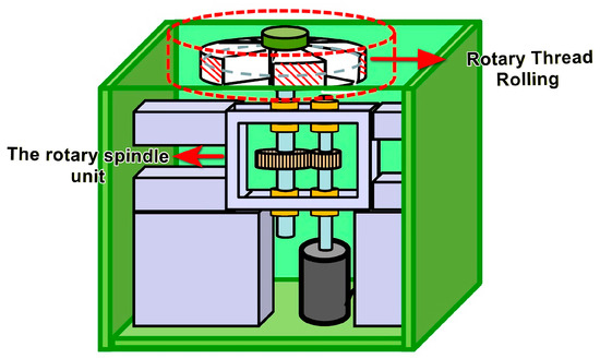
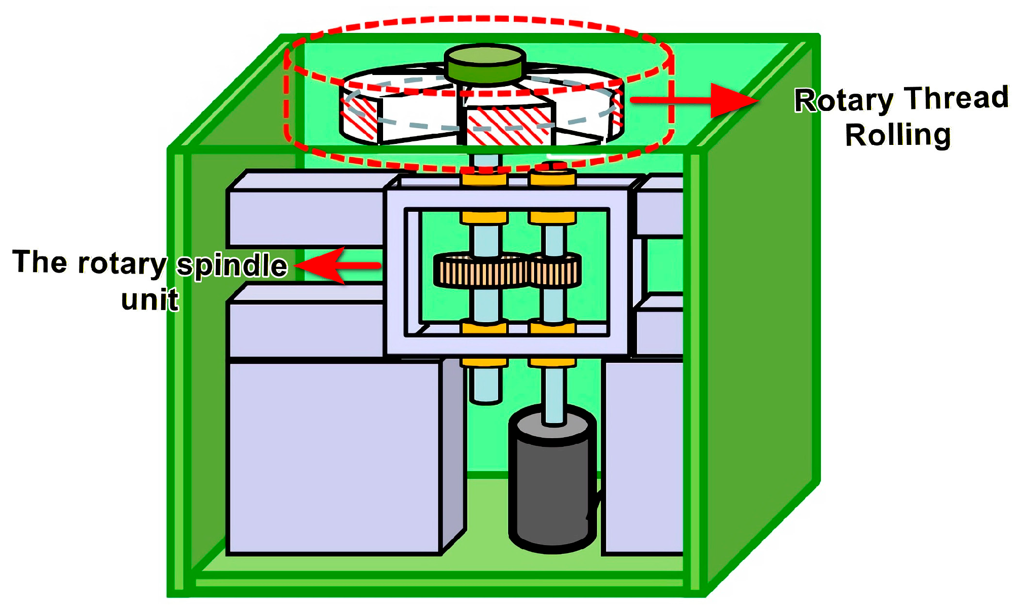
To address these issues, this study proposes a novel sector-shaped thread rolling mechanism that replaces the traditional linear feed with controlled rotational rolling motion (Figure 1). By altering the contact mode and motion trajectory between the dies and workpieces, the new mechanism aims to reduce inertia effects, enhance dynamic stability, and enable multi-piece simultaneous forming within a single rotation cycle.
Figure 1.
Schematic of the Novel Thread Rolling Machine.
A quantitative physical model was developed to describe the relationship between rolling motion parameters and forming quality indicators, including geometric accuracy, surface integrity, and dimensional consistency. Key parameters, such as die spacing and rotational kinematics, were incorporated into the analysis framework. Numerical simulations using DEFORM-3D were performed to study material forming results under different parameter combinations. The simulation results were then used as experimental test parameters, saving testing time while validating the accuracy of the DEFORM-3D results and further evaluating the system’s stability under practical operating conditions.
The primary goal of this equipment is to innovate and improve upon the CPR6 thread rolling machine, aiming to increase production efficiency and reduce costs. During development, the first step is to verify the operational feasibility of the equipment. To save time and costs, a simplified approach was adopted, utilizing the existing straight thread plate geometry of the CPR6 and directly bending it. Since the focus of this stage is to verify stable operation, the thread surface shape and depth have not been fully redesigned. The thread plate used in this stage is a simplified design, not the new plate specifically designed for this equipment.
This study aims to evaluate the applicability, reliability, and performance advantages of the proposed mechanism compared to traditional linear systems. By combining structural innovation, kinematic modeling, numerical simulation, and experimental verification, this work aims to provide both theoretical insights and engineering guidance for the development of compact, energy-efficient, and intelligent thread rolling equipment.
3. Theoretical Analysis of the Novel Thread Rolling Machine
Building upon the structural characteristics and operational parameters of the conventional CPR6 linear thread rolling machine, this study proposes an innovative rotary thread rolling system through systematic theoretical modeling and mechanical derivation. The proposed system integrates rotary forming mechanism modeling, mechanical structure design, thread rolling die optimization, and spindle drive–motion control coordination. The theoretical framework and derivations are presented as follows.
3.1. Thread Rolling Forming Principle
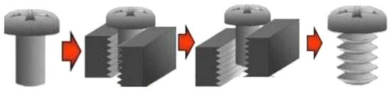
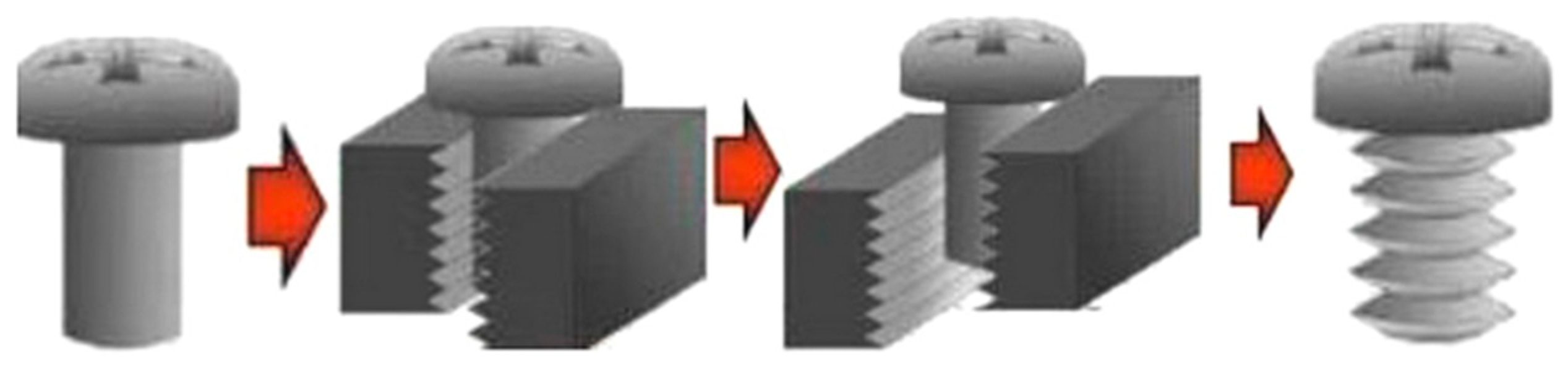
Thread rolling is a cold plastic forming process widely applied in precision screw manufacturing. During operation, a cylindrical screw blank is positioned between a stationary die and a moving die. Under controlled relative motion and high contact pressure, the material undergoes localized plastic flow and surface restructuring, gradually forming the required thread geometry. The thread forming mechanism and motion trajectory are illustrated in Figure 2.
Figure 2.
Schematic of the thread rolling forming process.
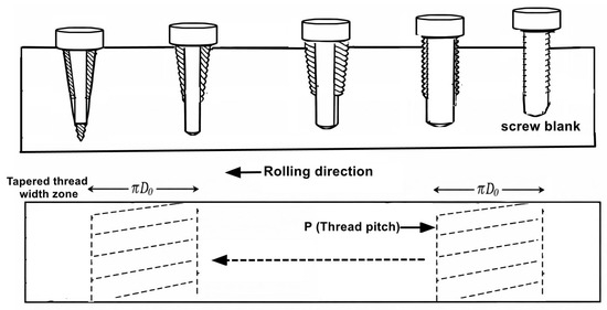
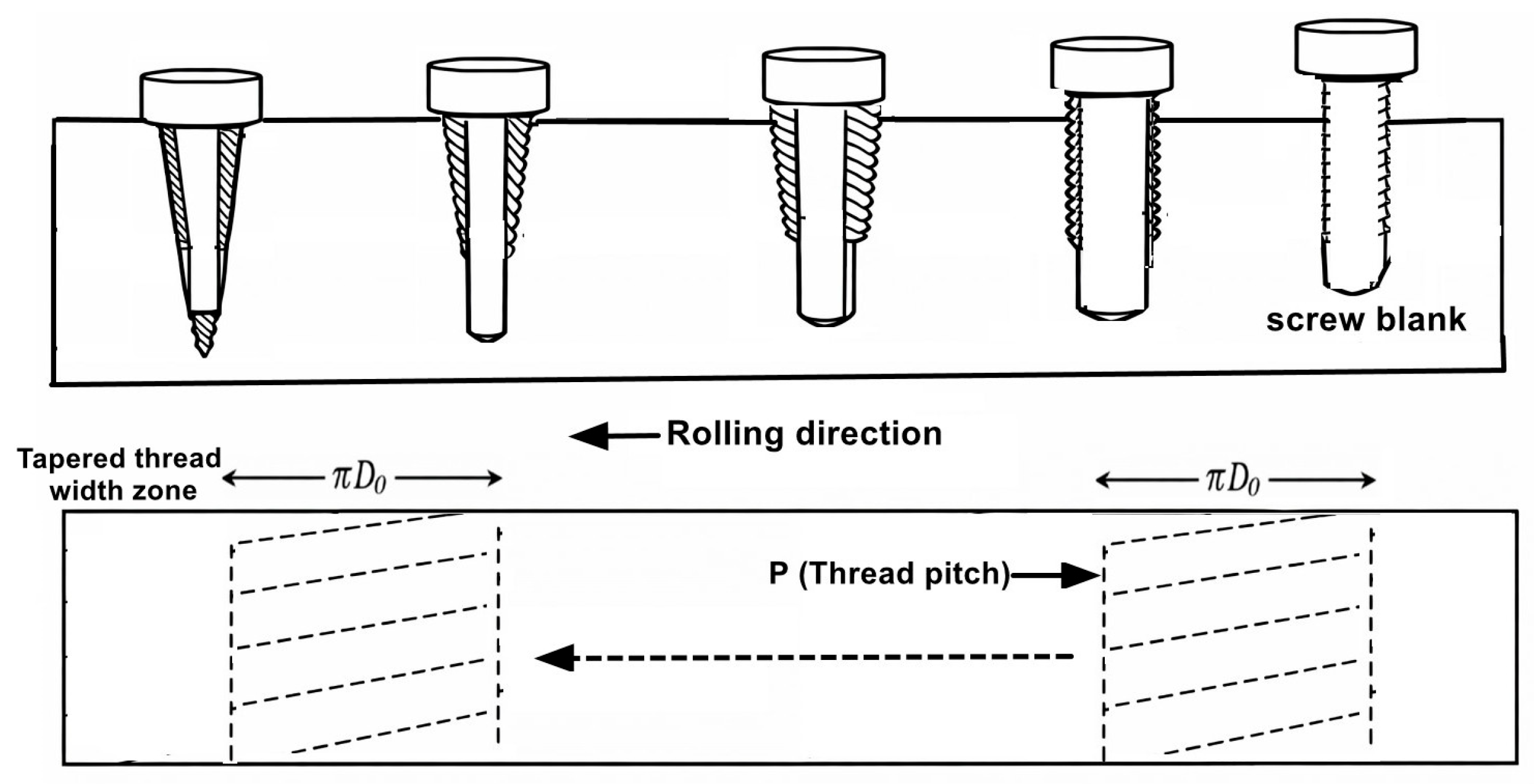
In practical applications of flat-die thread rolling, the material undergoes continuous plastic flow and deformation throughout the entire rolling stroke, as illustrated in Figure 3. The screw blank rolls and advances between the two dies, and as the contact time and deformation gradually increase, the thread is progressively formed from shallow to full depth. In this process, the initial diameter of the screw is denoted as , and the thread pitch is . When the screw rolls one complete revolution on the die, the corresponding axial displacement along the rolling direction is . This distance determines the developed length of the thread on the die and the design of the effective forming zone.
Figure 3.
Schematic illustration of the distribution of plastic deformation throughout the thread rolling process.
Furthermore, when a pointed tip is required, the thread width must be intentionally adjusted at the end of the die to achieve truncation of the screw tail. A tapered thread-width region is therefore designed so that the thread gradually converges during the final stage of rolling and the material filling is reduced. This tapered thread-width zone is located at the end of the flat die, corresponding to the final rolling stage illustrated in Figure 3. Through this adjustment of the thread width, controlled plastic flow and extrusion occur at the end of the rolling process, enabling the truncation and pointed-tip formation of the screw. As a result, the finished screw achieves improved penetration and assembly performance.
3.2. Mechanical Analysis of the Linear Thread Rolling Process
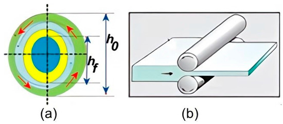
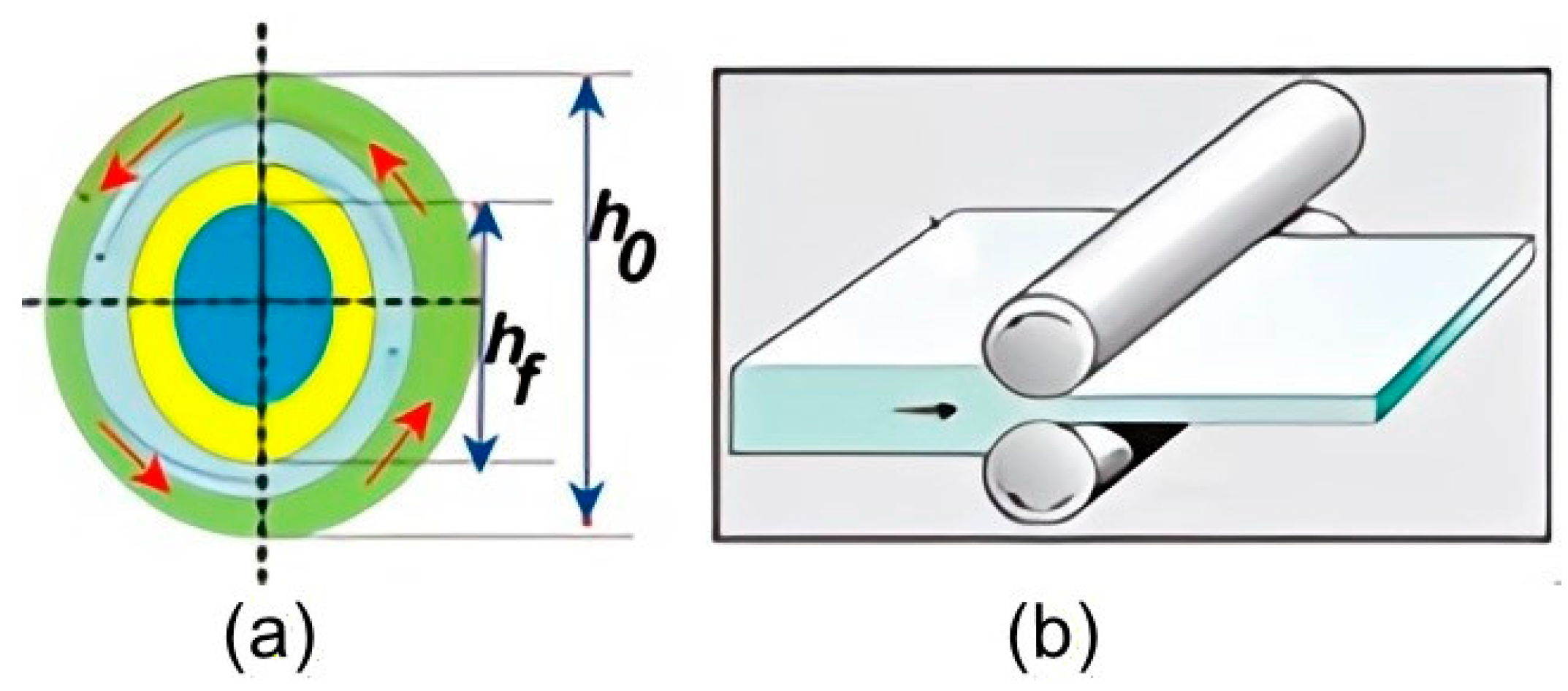
To design the structural strength of the thread rolling machine body and to properly select the spindle drive motor, it is necessary to systematically analyze the stress state of the screw throughout the rolling thread process. By sectioning the screw along the radial direction and observing its deformation, the thread rolling plastic deformation can be equivalently regarded as a localized rolling plastic deformation occurring over a certain contact length, i.e., the screw’s rolling contact distance. The deformation mechanism is illustrated in Figure 4, where represents the initial thickness of the screw material, and denotes the final thickness after thread rolling, corresponding to the geometric state of the material after plastic flow in the compressed region [38,39].
Figure 4.
Screw plastic deformation during thread rolling. (a) Cross-section showing material flow and thickness reduction; (b) Side view of the workpiece passing through the rollers.
In this study, plastic deformation during thread rolling is defined as the localized compressive plastic flow that occurs within the contact zone between the rolling dies and the screw blank. When the screw passes through the rolling region, the material is subjected to high radial compressive stress exceeding the yield strength, causing permanent deformation without material removal. The material originally located at the outer cylindrical surface flows radially outward and tangentially along the die tooth profile, gradually forming the thread geometry.
From a geometric perspective, this plastic flow can be equivalently characterized by the reduction in the effective material thickness from the initial value to the final value . The deformation is not uniform along the screw axis but is concentrated within a finite rolling contact length where the material experiences repeated incremental deformation during successive rotations. Therefore, the overall thread forming process can be regarded as a multi-pass localized plastic compression process, in which the total deformation is accumulated progressively over rolling rotations.
This definition provides the physical basis for the simplified force analysis and the estimation of rolling contact length used in the following derivations.
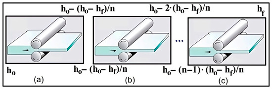
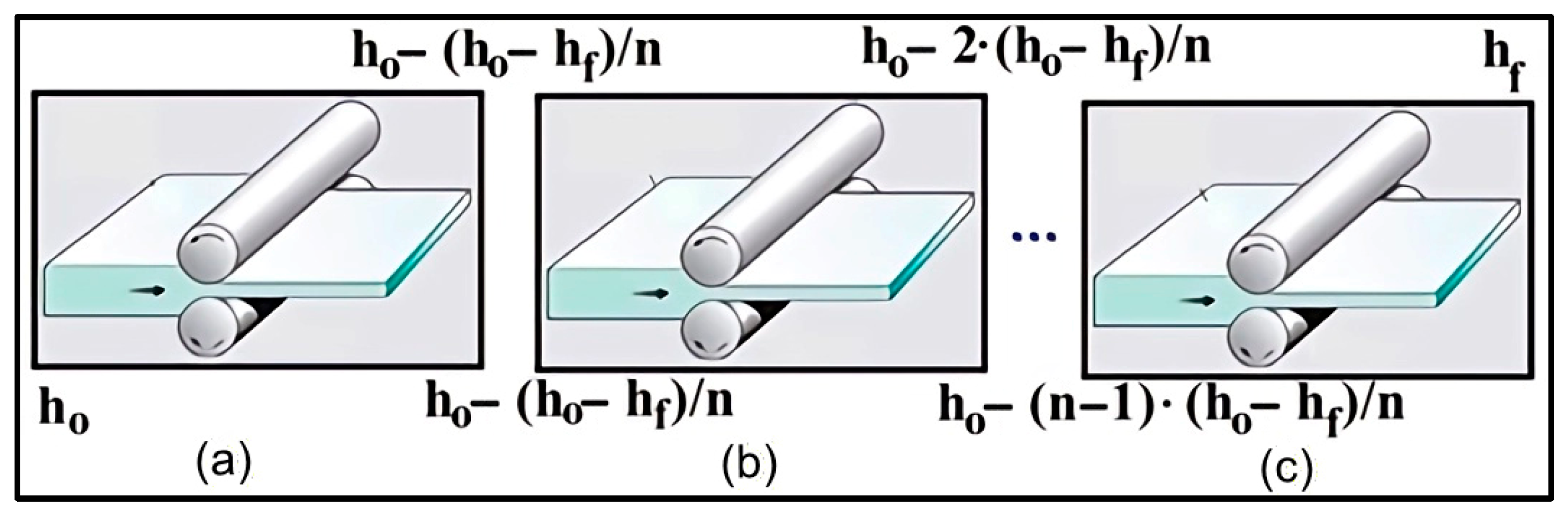
Assuming the screw has an initial diameter and a final diameter , and undergoes rotations during the thread rolling process (Figure 5), the total deformation is . The average deformation per rotation is . The contact length can be expressed as:
Figure 5.
Progressive thread rolling stages illustrating the reduction in workpiece height from to ; (a) initial contact at height , (b) intermediate rolling stage with height , (c) final stage at height .
The average radius for each rotation can be expressed as:
In terms of processing method, thread rolling is classified as a compressive forming process, with contact area and material removal significantly smaller than in flat-die rolling. Consequently, the forming force required for thread rolling is relatively lower. To ensure sufficient safety margin and computational reliability, empirical formulas based on the flat-die rolling approximation are typically employed. Accordingly, this study adopts Equation (3) to estimate the radial force in thread rolling, providing a reliable calculation basis and reference data [40,41].
where
The contact length and the average radius per rotation are calculated using Equations (1) and (2), respectively. represents the screw’s cylindrical length, denotes the material hardness, and is the friction coefficient.
Under the assumption of uniformly distributed thread load and average rolling, the radial force , screw rotational speed , rolling period t, and thread rolling process power can be expressed by the following equations:
The currently used thread rolling machine by the manufacturer is the CPR6 model, with a maximum production capacity of 400 pieces per minute, equivalent to approximately 7 screws per second, resulting in a single-piece processing cycle of about 0.14 s. The machine is equipped with a 7.5 hp (approximately 5.5 kW) spindle motor and has a net weight of 1500 kg, demonstrating excellent stability and strong processing capability in high-speed, large-scale production environments. The design of the new thread rolling machine takes the CPR6 specifications as a benchmark, serving as an important reference for system performance, power requirements, and mechanical configuration. Assuming the screw diameter is (in meters), the feed distance per revolution of the screw is . If the rolling process requires revolutions, the total travel distance of the screw during processing is meters. Based on the above production cycle, the minimum required feed speed of the screw can be expressed as m/s. Considering practical applications, the mechanism must have at least a 25% margin to accommodate load fluctuations and machining accuracy requirements, while also simplifying the design. Therefore, the unidirectional movement speed of the new mechanism is set to:
This design not only ensures the stability of the equipment under high-speed mass production but also provides a solid foundation for subsequent system optimization and intelligent control.
3.3. Mechanical Analysis of Rotary Thread Rolling
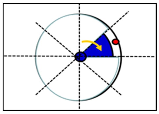
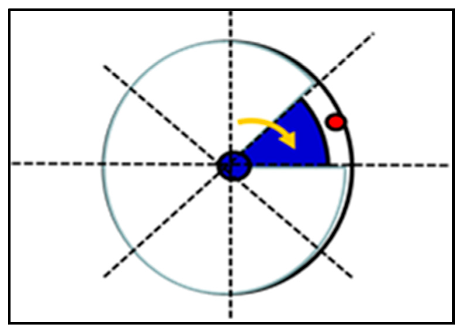
If the unidirectional linear motion is converted into rotational motion, one full rotation can complete a single thread rolling operation. The entire thread rolling process corresponds to the screw rolling over n rotations, which can be regarded as a sector-shaped rotational motion. Figure 6 illustrates this concept, providing a clear depiction of the motion characteristics during the forming process.
Figure 6.
Sector-shaped rotational motion.
Assuming the circular dimension is sufficiently large and one rotation is divided into 8 equal sector segments, the velocity relationship is expressed as follows:
where is the disk diameter, is the motor speed in revolutions per second (rps), and is the mechanism’s linear velocity per sector (with one rotation divided into 8 segments). From Equation (8), it can be seen that
And
where is the screw diameter, is the number of screw rotations, and is the motor speed in revolutions per minute (rpm), the velocity relationship can be expressed as:
Thus, the design relationship among motor speed, disk size, and screw diameter can be expressed as:
If one rotation is divided into sector-shaped segments, under the same production requirement, the motor speed can be reduced to .
Since the CPR6 spindle motor has a power of 5.5 kW, if the motor’s rated speed is (rad/s), then the output torque can be calculated as:
If a full rotation is divided into sector-shaped dies operating simultaneously, the motor torque must be increased by a factor of Similarly, if the rated speed is reduced by a factor of through a gearbox, the motor torque can be increased by times. Naturally, the selection of the rated speed must be based on the optimal thread rolling speed for the process.
The screw processing rate is 400 pieces per minute, which corresponds to approximately 7 pieces per second, meaning 7 complete processing cycles must be completed every second.
From the perspective of rotational motion, each processing cycle corresponds to one full rotation of the spindle, meaning one thread rolling operation is completed per revolution. Therefore, the spindle rotational speed can be expressed as:
The above calculation indicates that the thread rolling machine spindle must maintain a stable rotational speed of 420 revolutions per minute to achieve the desired production efficiency.
According to Equation (8), it can be deduced that:
Here, and .
In terms of mechanical analysis, the tangential force at the processing contact point can be determined by the following equation:
3.4. Kinematic Analysis of Rotary Thread Rolling
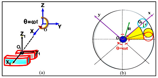
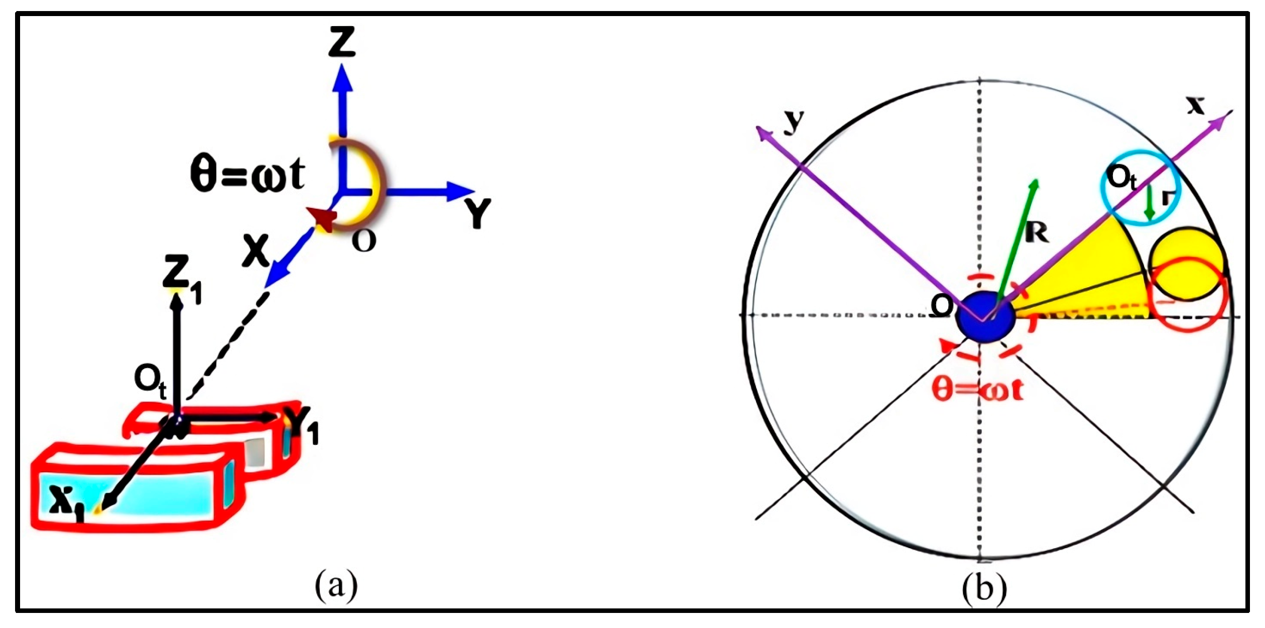
The design concept of the novel thread rolling machine originates from the innovative idea of a sector-shaped rotary rolling mechanism. In the study of the thread forming mechanism, accurate and comprehensive kinematic modeling is of critical importance. To ensure that the model realistically reflects the actual machining conditions, a rigorous and unified spatial coordinate system must first be established, including the screw workpiece coordinate system, the thread rolling die coordinate system, and the machine base coordinate system, along with clearly defined transformation relationships between them. Based on this framework, kinematic parameters are further derived and calculated to systematically describe the instantaneous relative motion between the rolling dies and the screw workpiece. The results of the geometric modeling and kinematic derivations are illustrated schematically in Figure 7a,b.
Figure 7.
Schematic illustration of the geometric and kinematic model of rotary thread rolling: (a) coordinate system; (b) rolling geometry.
From the geometric relationships, it follows that:
where R is the disk radius, is the screw radius, and the initial coordinates of the screw center point are .
During the thread rolling process, the displacement of the movable die is:
The displacement of the screw center point is:
The rotation angle of the screw center point relative to the disk center point is:
The rotation angle of the screw center point can be expressed as:
Therefore, the coordinates of are given by
4. Design and Manufacturing of the Novel Thread Rolling Machine
Building on the preceding theoretical analysis and technical discussion, the complete design and physical fabrication of the thread rolling machine will be carried out. Through a systematic design and implementation process, the machine is ensured to achieve high precision, stable operation, and excellent processing efficiency. The relevant details are described as follows.
4.1. Design Methodology of the Rotational Thread Rolling Machine
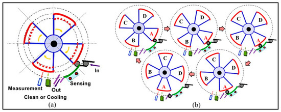
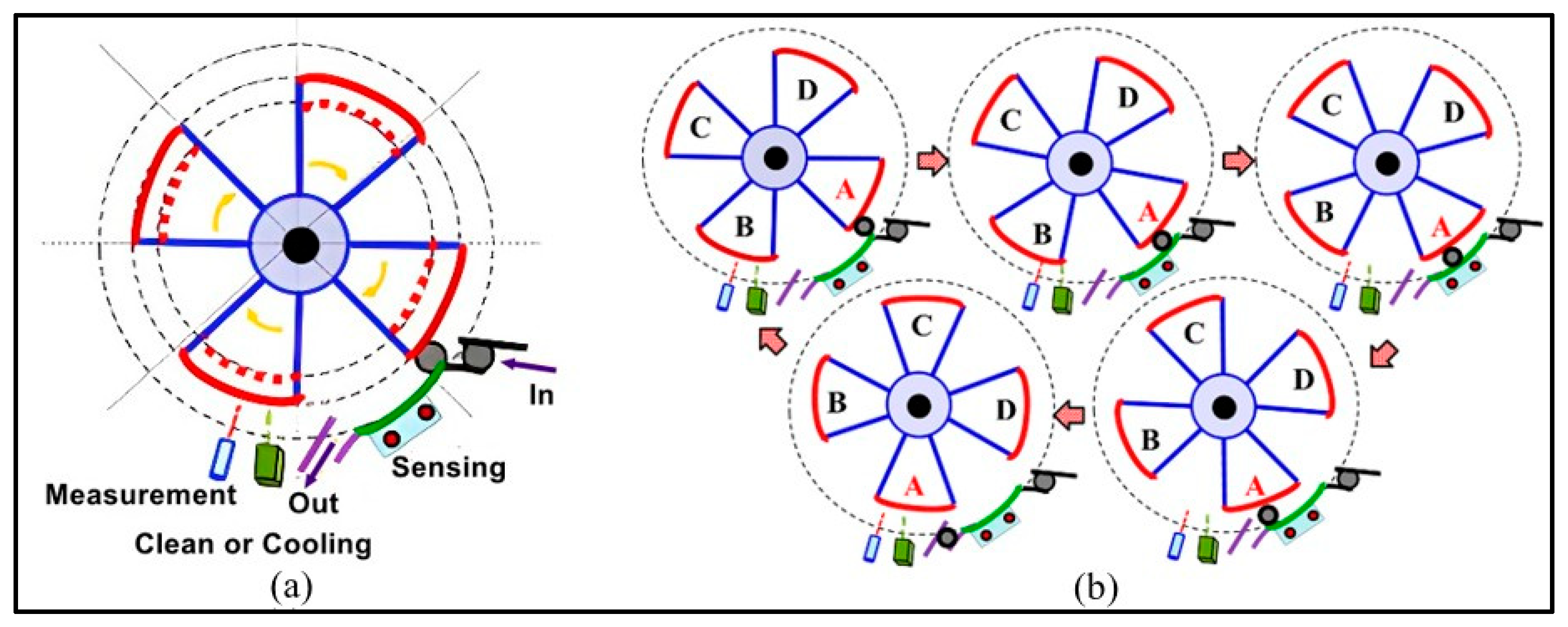
The schematic design concept of the novel thread rolling machine is illustrated in Figure 8a. The overall structure adopts an eight-segment disk configuration, with four segments dedicated to simultaneous screw thread rolling and the remaining four reserved as idle segments for auxiliary operations, including post-rolling sensing, cooling, cleaning, and die measurement. This study primarily focuses on the motion implementation and forming results of the screw thread rolling process. Once system stability and processing accuracy meet the expected criteria, subsequent research will integrate monitoring and feedback control functionalities.
Figure 8.
Schematic illustration of rotational thread rolling in the novel machine: (a) design concept; (b) thread rolling process.
In the schematic shown in Figure 8b, each thread rolling cycle begins as the screw blank enters the rolling zone, where the die gradually contacts the screw shank. The thread is rolled and plastically formed through sector-shaped rotational motion. Each frame in the figure illustrates the relative positions and contact states between the die and the workpiece: during the initial contact stage, the die applies pressure to the screw, initiating material plastic flow; as the sector rotation progresses, the workpiece surface is incrementally rolled, gradually forming the thread profile; in the mid-formation stage, the die maintains continuous local contact with the screw, ensuring uniform material flow under controlled stress and preventing localized over-deformation or voids; in the final stage, the thread approaches its final shape, the die completes the thread profile replication, and the workpiece gradually moves axially out of the processing zone. Throughout the thread rolling process, continuous sector contact enables precise plastic thread formation, with die forces, surface stress distribution, and micro-displacements dynamically adjusted to ensure geometric accuracy, surface integrity, and processing stability.
4.2. Design of Rotational Thread Rolling Dies
In the conventional CPR6 thread rolling machine, both the fixed and moving dies are designed with linear profiles. In the new machine design, to enhance processing efficiency and compactness, the die shape is modified. However, due to the complexity and time-intensive nature of die surface design and manufacturing, the study retains the original die geometry. To achieve an optimal balance between machine size and screw forming accuracy, while minimizing the effect of die shape on rolling outcomes, a curved die design is implemented.
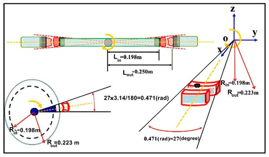
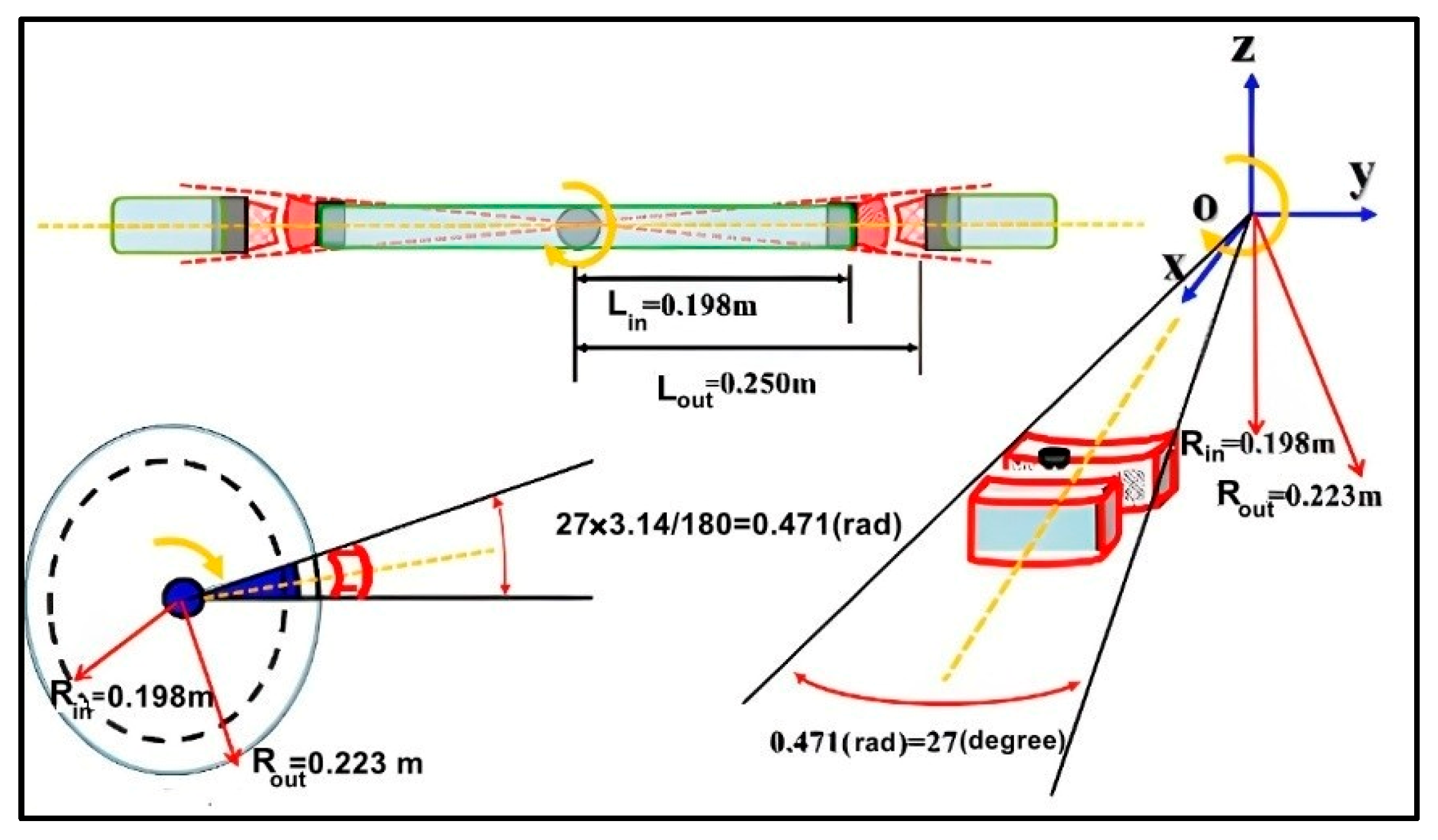
According to Equation (13), the minimum rotating disk diameter is determined based on the relationship between rotational speed, rolling cycles, and screw diameter. In this case, n represents the number of rolling revolutions required for a screw to complete the thread forming process within the effective rolling zone. With ω = 420 rpm, n = 5, and a screw diameter D = 6 mm, the calculated minimum required disk diameter is 342.86 mm. As a result, a rotating disk diameter of 396 mm is selected to ensure a sufficient safety margin while also simplifying manufacturing and assembly. The curvature angle of the moving die is set to 0.471 rad, while the fixed die adopts a linear profile. The main structure and relative dimensions of the dies are illustrated in Figure 9.
Figure 9.
Schematic of the relative dimensions of the thread rolling mechanism in the novel thread rolling machine.
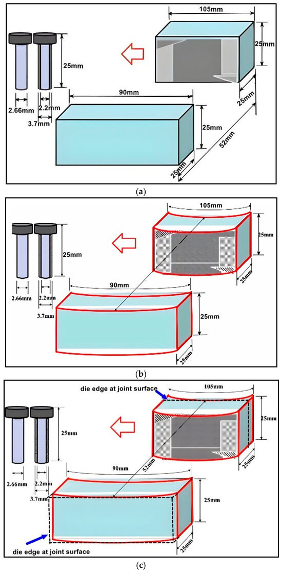
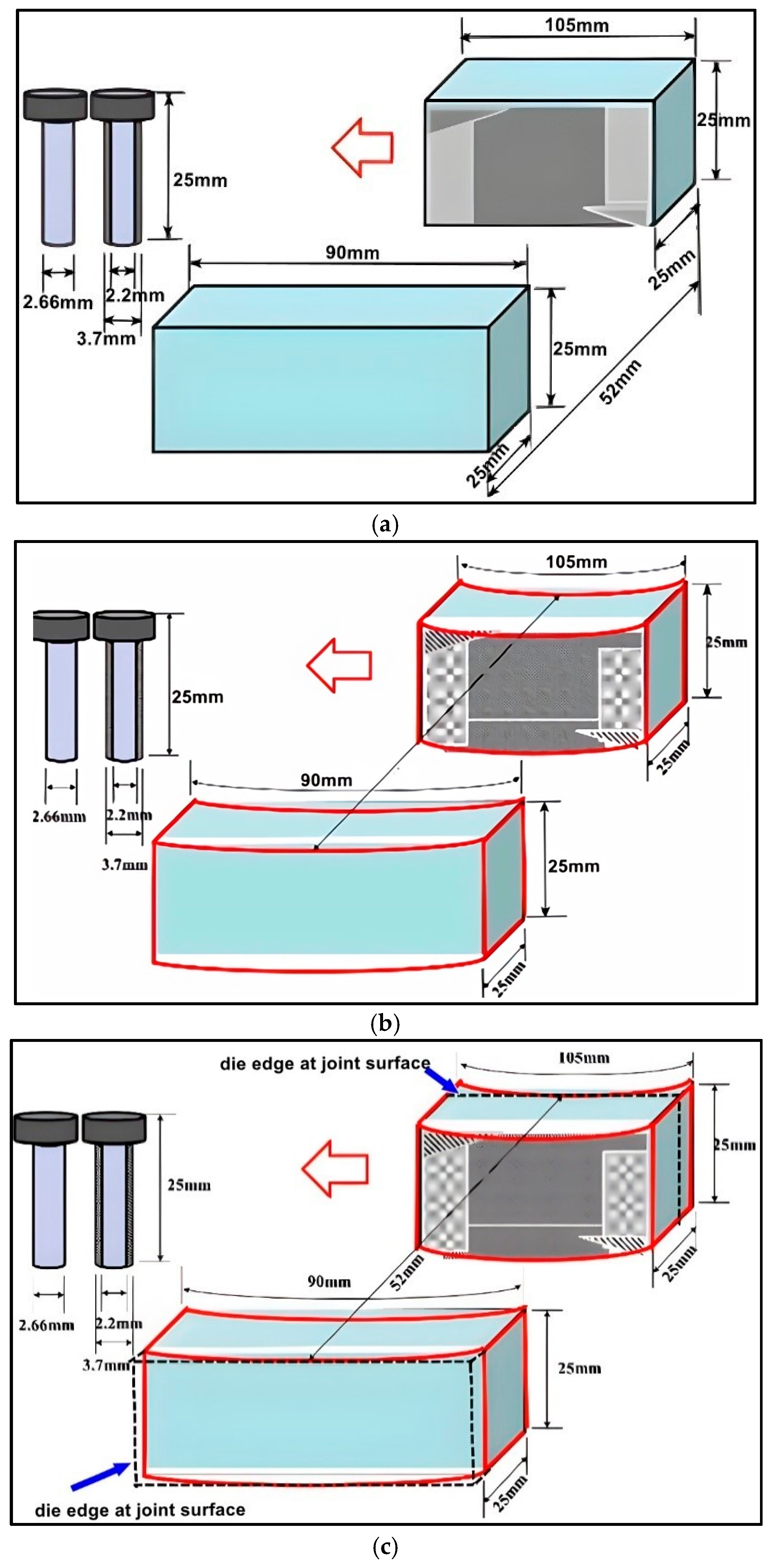
The screws and the original linear dies selected for this study are shown in Figure 10a, where the thread rolling operation is linear and the relative distance between the reference planes of the two dies is 52 mm. For the arc-shaped bending design based on the original die length, the die dimensions need to be determined according to the selected screw specifications and the geometric shape of the sector-shaped die, as illustrated in Figure 10b, while retaining the original rotational thread rolling mechanism. During the actual drafting of the bent dies, the original dimensions are used as a reference, but slight adjustments to the die body geometry are made to accommodate manufacturing and assembly requirements. Moreover, to ensure accurate alignment during installation, the contact surfaces and die edges interfacing with the mechanism are specially designed as right-angled, facilitating positioning and stability. The black dashed lines in Figure 10c indicate the die-to-mechanism interface contour, which helps maintain the processing reference plane and ensures that the bent dies can be stably integrated into the overall thread rolling system.
Figure 10.
Schematic illustration of the dimensional change from straight dies to curved dies from (a) to (c).
4.3. Mechanical Design of the Rotational Thread Rolling System
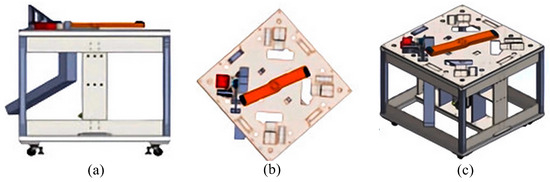
The proposed rotational thread rolling machine was developed to investigate the structural feasibility and motion characteristics of a sector-shaped rolling mechanism. The mechanical architecture was designed with a reduced number of transmission interfaces to simplify assembly and alignment during experimental setup. A rotational rolling unit and die system were arranged in a coordinated configuration to maintain stable engagement between the dies and the screw blank throughout the rolling cycle. This configuration enables continuous material deformation under controlled contact conditions and supports repeatable forming experiments.
To facilitate experimental adjustment, the machine adopts a modular structural layout. Key components, including the rolling dies, rotational mechanism, and feeding unit, can be repositioned and replaced to accommodate different testing conditions. This modular configuration allows systematic variation in process parameters during experimental trials without major structural modifications.
The overall machine layout and spatial arrangement of the main structural modules are shown in Figure 11. This configuration provides a physical platform for evaluating forming stability, controllability, and the feasibility of the proposed rolling mechanism.
Figure 11.
Rotational thread rolling mechanism design: (a) side view; (b) top view; (c) overall view.
4.4. Construction of the Novel Thread Rolling Machine
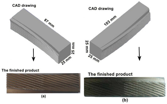
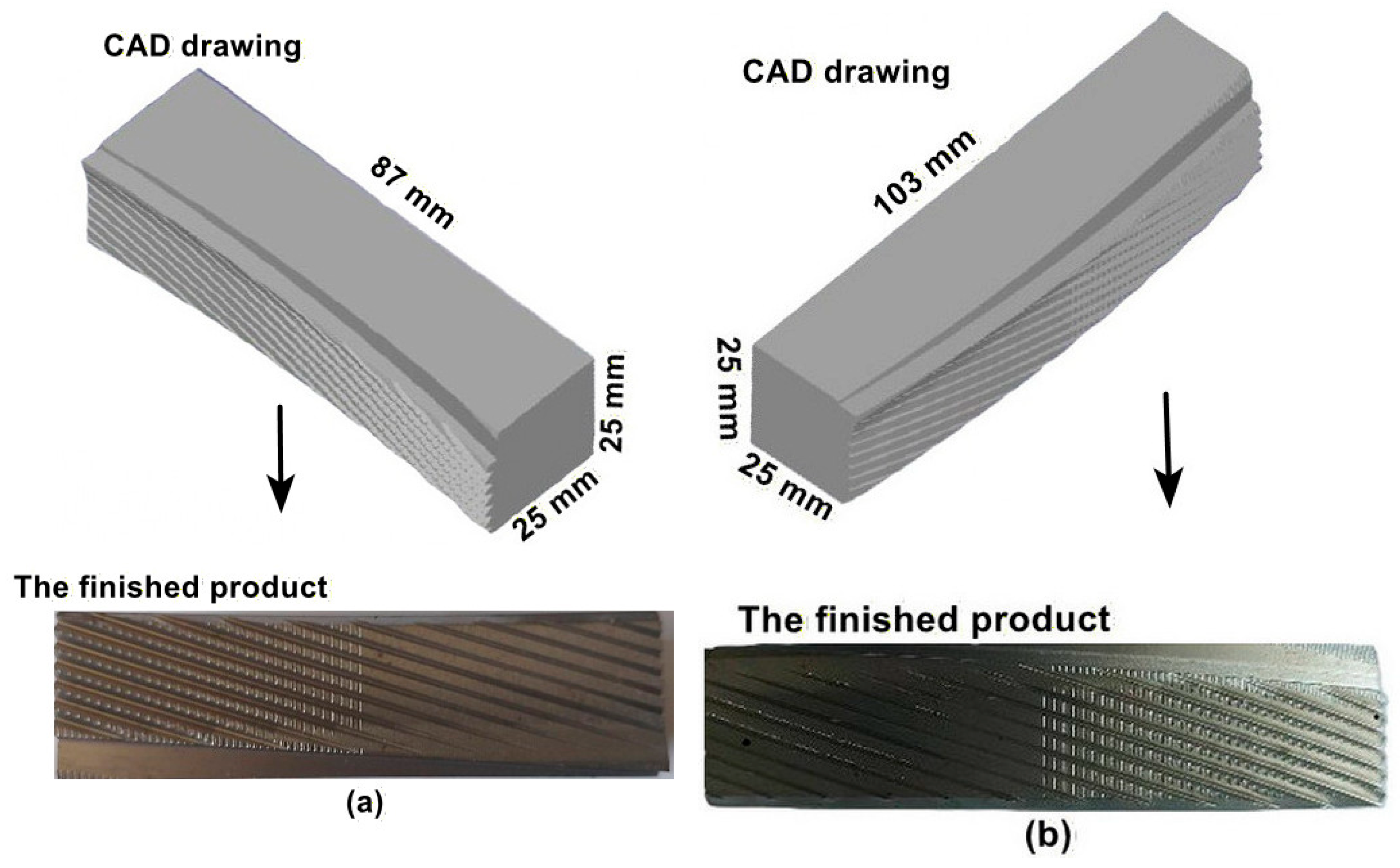
The design and fabrication of the thread rolling dies are critical to both screw thread quality and machine performance. In this study, the geometry of the rotating thread rolling dies was optimized based on theoretical bending angles. The original features of conventional linear dies, such as thread profile, tooth angle, and tooth width, were largely preserved to ensure stable contact and efficient rolling during plastic deformation. By controlling die curvature, the rotating dies maintain the characteristics of rotational thread rolling while enabling comparison with screws formed by conventional linear dies, facilitating the evaluation of different rolling methods on thread quality.
The thread rolling dies are made from SKH9 high-speed tool steel, compliant with Japanese Industrial Standards, and are reinforced through heat treatment to enhance microstructure stability and wear resistance. After heat treatment, the dies reach a hardness of HRC62–64, with an average of HRC63, enabling them to withstand high-load, high-frequency rolling stresses and extend service life. The dies undergo precision grinding and surface finishing to ensure accuracy in tooth profile and surface roughness, meeting design specifications. The final curved dies, including both the CAD model (developed using AutoCAD 2019) and the manufactured dies, are shown in Figure 12.
Figure 12.
Finished curved thread rolling dies: (a) fixed die; (b) movable die.
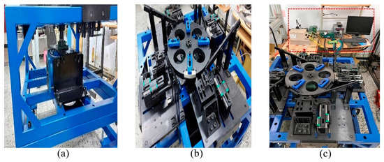
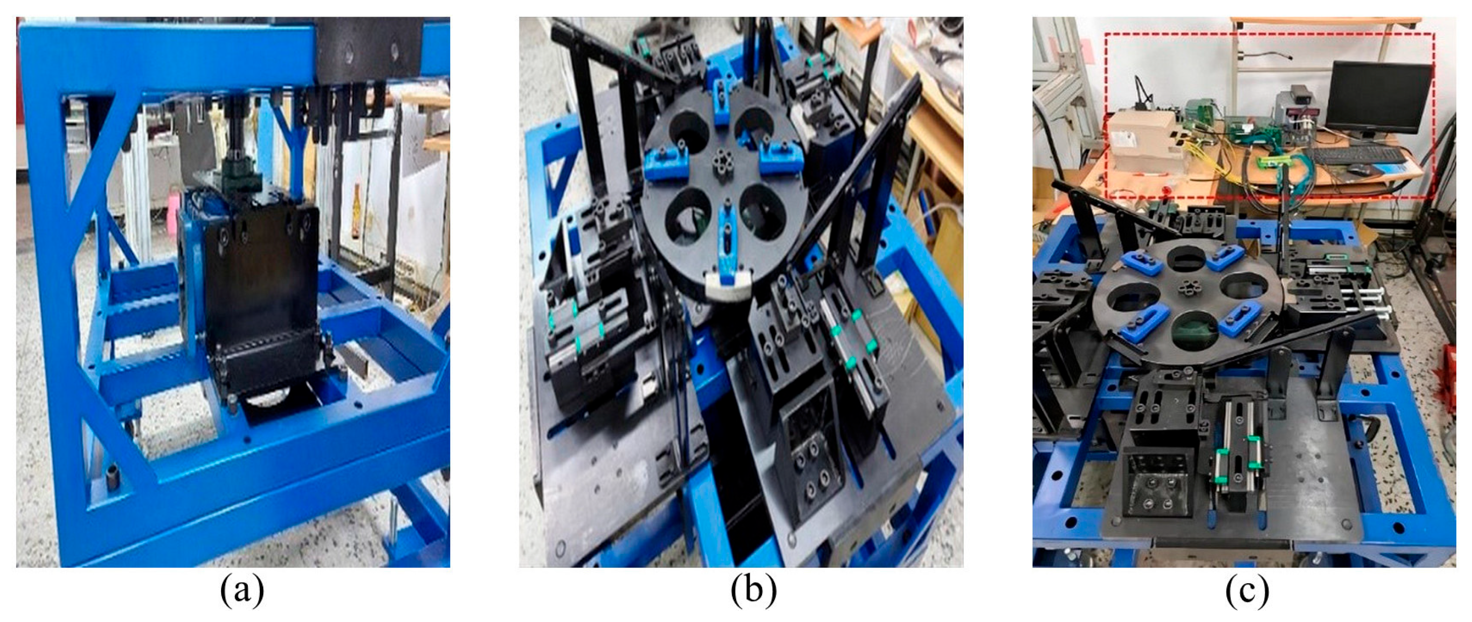
Based on the design specifications derived in Section 3.3, the completed novel thread rolling machine comprises the machine body, feeding mechanism, die fixing assembly, and rotary spindle fixation unit. The rotary spindle unit, as the main driver of the rolling motion, ensures high precision, coaxiality, and wear resistance to maintain stable, synchronized movement and prevent defects or abnormal wear. To meet the high torque and speed requirements, the spindle drive system (Figure 13a) uses a Schneider BCH1805M12F1C servo motor with a Lexium 23 Plus servo driver, delivering 7.5 kW output and up to 3000 rpm, providing stable, precise, and repeatable control. The equipment is manufactured by Schneider Electric, headquartered in Rueil-Malmaison, France. After precise assembly and dynamic adjustment, the fully assembled machine is shown in Figure 13b. The design balances structural rigidity, mechanical stability, and operational convenience, providing a reliable foundation for thread forming tests and integration with the control system.
Figure 13.
Structure of the novel thread rolling machine: (a) spindle drive system, (b) mechanical assembly, and (c) electrical control system.
The electronic control system of the novel thread rolling machine, shown in the red dashed box of Figure 13c, features a modular architecture that includes a computer, digital I/O interface, servo control board, and machine body. At its core, the FPGA-based servo control board enhances control accuracy and operational efficiency with its high-speed parallel computing capabilities. Bidirectional communication between the control board and AC servo driver is facilitated through pulse, direction, start, status feedback, and high-resolution encoder signals, ensuring synchronized motion. The servo motor, equipped with a high-resolution incremental encoder (160,000 pulses per revolution), provides real-time position feedback for precise thread forming. A PID control strategy is employed to maintain stable spindle performance under variable loads, continuously adjusting based on feedback signals [42,43,44]. The PID parameters are tuned for inertia and friction characteristics, enabling smooth and precise motion control, improving stability and efficiency.
5. Simulation and System Testing of the Novel Thread Rolling Machine
To verify the applicability and stability of the proposed new thread rolling machine, finite-element simulations were first conducted using DEFORM-3D software [45,46,47] to evaluate the feasibility of screw forming under different parameter settings after simply designing the linear dies of the conventional CPR6 thread rolling machine as curved dies. Based on the simulation results, the new thread rolling machine was constructed, and the die spacing as well as related process parameters were optimized. During the experimental phase, precise die alignment was performed, and the feeding and control systems were fine-tuned to ensure stable operation of the machining process. Finally, multiple forming tests were carried out using the die spacing adjustment mechanism. These tests served to validate the simulation results on one hand, and on the other hand, to compare the thread quality with that produced by the conventional CPR6 thread rolling machine, thereby verifying the overall reliability and machining performance of the system.
5.1. Numerical Simulation of the Novel Thread Rolling Process
In the novel thread rolling machine proposed in this study, the original straight dies are redesigned into curved profiles while preserving the original tooth surface geometry of both dies. As described in Section 4.4 and Figure 12, the CAD drawing presents the detailed dimensions of the thread rolling dies. To evaluate the feasibility of this modified die configuration for screw blank forming, numerical simulations were performed using DEFORM-3D v11 software.
In accordance with the design specifications of the proposed machine, the moving die works in conjunction with the fixed die at an assumed rolling speed of 1000 mm/s to complete the forming process. The screw blank used in the simulation measures 3.5 × 35 mm and is made of AISI 1020 steel, matching the dimensions specified by the manufacturer for the finished product. Both the screw blank and the dies were set to an initial temperature of 25 °C, representing typical room-temperature cold rolling conditions.
In the numerical simulation, the contact behavior between the dies and the screw blank was modeled using the shear friction model in DEFORM-3D. The friction coefficient was not adopted as a standard value for lubricated cold forming, but was instead determined through a parameter calibration process during the early stage of machine design. At this stage, the primary objective was to evaluate whether the proposed curved die geometry could successfully achieve screw forming. Therefore, DEFORM simulations were first conducted to explore the rolling behavior using AISI 1020 steel, while systematically varying key parameters including mesh density, die spacing, and friction coefficient. Other simulation settings followed the default recommendations of the software. Since the proposed curved die structure is a novel design and no directly comparable literature data are available, the friction coefficient was determined through repeated simulation-based calibration.
The convergence criteria in the DEFORM-3D simulation were defined by a force tolerance of 0.005 and a velocity tolerance of 0.01. The maximum number of iterations per step was set to 20 to ensure numerical stability and solution accuracy. Automatic time stepping was employed, with a minimum time increment of 1 × 10⁻⁵ s, to prevent contact instability and numerical divergence during high-speed rolling.
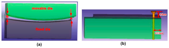
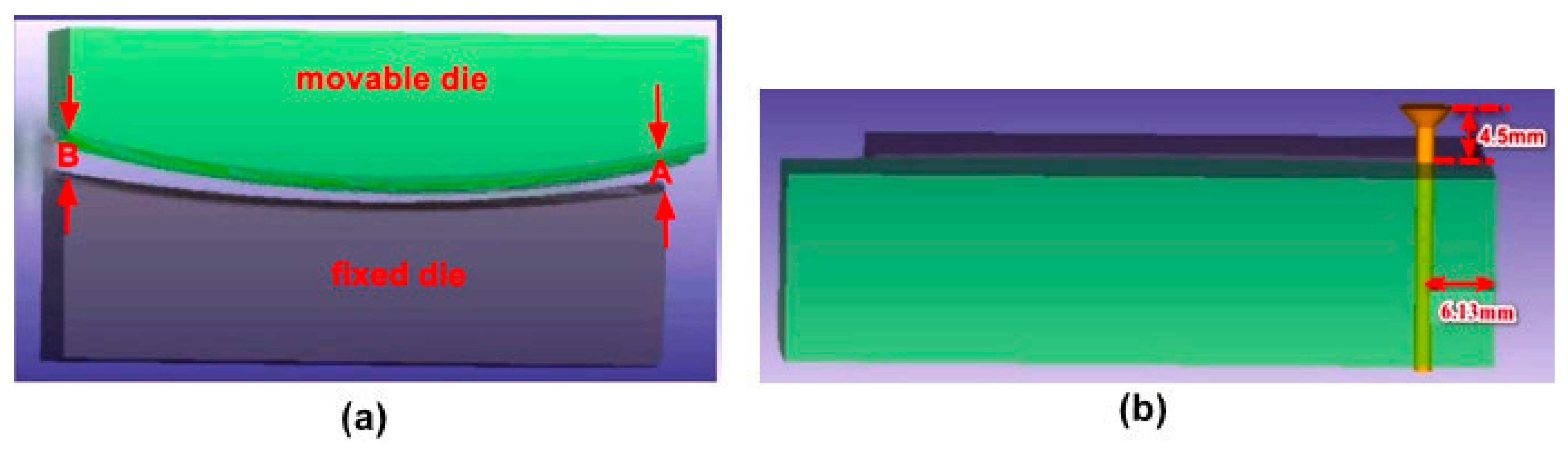
In the simulation of the screw thread rolling process, multiple sets of parameters were examined, including the mesh density of the screw blank, the initial height between the screw head and the dies, and the initial feeding position of the screw blank (as shown in Figure 14). Through repeated simulations, the key influences of these parameters on the rolling process were identified, and the die spacing was optimized accordingly. A representative set of simulation conditions was summarized in Table 1, and was used in the numerical simulation of the novel thread rolling machine to verify the feasibility and practicality of the overall design.
Figure 14.
Key parameters of the curved-die thread rolling simulation: (a) die spacing; (b) screw feeding position and initial height.
Table 1.
Simulation and Test Parameters for the Novel Thread Rolling Machine.
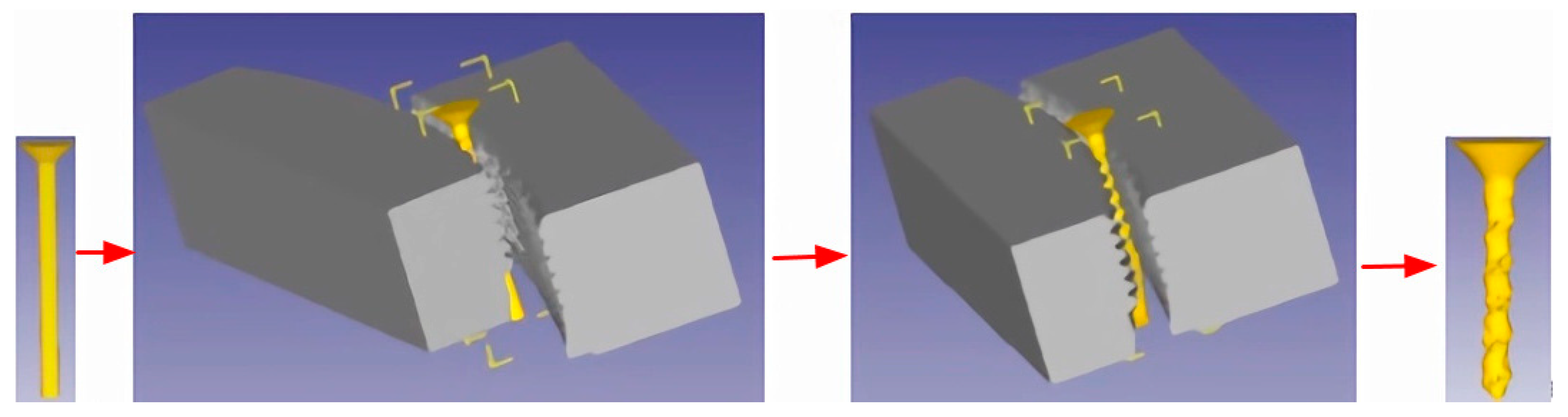
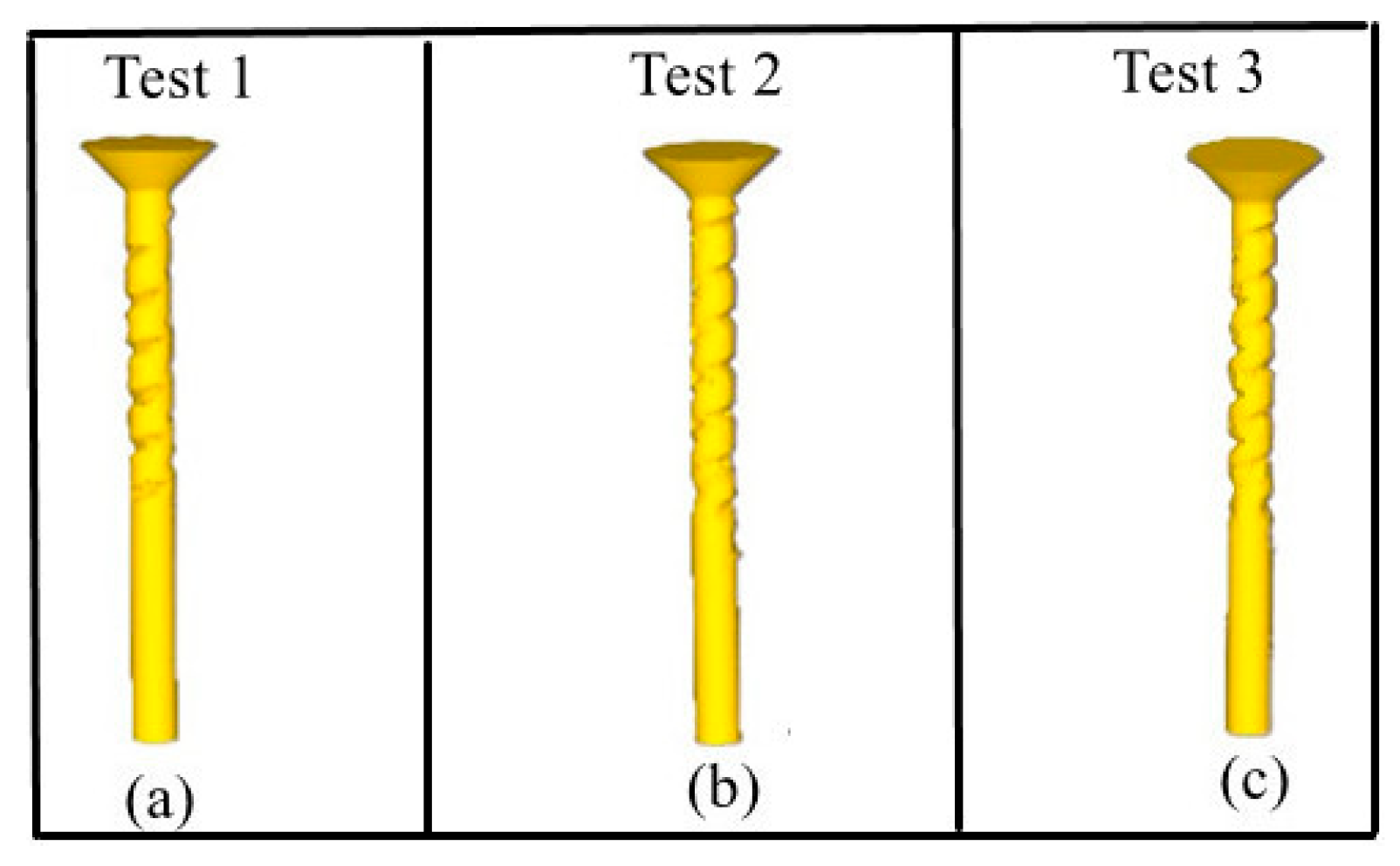
During the thread rolling simulation of the screw blank using Deform 3D, it was found that the friction coefficient between the die plates and the screw blank significantly affects the rolling behavior (Figure 15). According to the results of Tests 1–4 in Table 1, with a fixed die plate spacing, simulations were conducted for different friction coefficients. In Test 1, with a friction coefficient of 0.4, the simulation showed that approximately half of the screw blank’s travel occurred through rolling, while the remainder was completed by slipping. In Test 2, increasing the friction coefficient to 0.6 noticeably raised the proportion of rolling travel to more than two-thirds of the total stroke. In Test 3, further increasing the friction coefficient to 0.8 resulted in about three-quarters of the stroke being rolling, with the remainder slipping. When the friction coefficient reached 1.0 (Test 4), the simulation results were similar to those at 0.8, indicating that 0.8 represents a critical value, beyond which the motion pattern is not significantly affected. From the simulations of Tests 1–3 (Figure 16), although the overall thread profile remained similar, increasing the friction coefficient gradually produced a clearer thread profile and deeper forming depth. For Test 4, the thread quality was nearly identical to Test 3, with no further improvement. Additionally, all four simulations indicated that the screw tail was not fully formed, and the final product did not yet have a complete thread.
Figure 15.
Thread rolling process with curved die plates.
Figure 16.
Simulation results of the thread rolling process: (a) Test 1; (b) Test 2; (c) Test 3.
Based on the simulation results from Tests 1 to 4, although the screw blanks had not yet reached a fully formed state, it was clearly observed that increasing the friction coefficient significantly influenced the rolling behavior of the blanks between the die plates and contributed to an increase in thread depth. Therefore, in subsequent simulations, the friction coefficient was fixed at 0.8 to ensure stable rolling and promote improved thread formation quality.
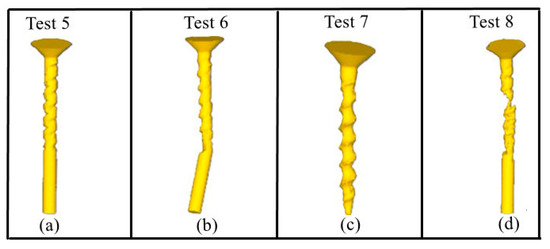
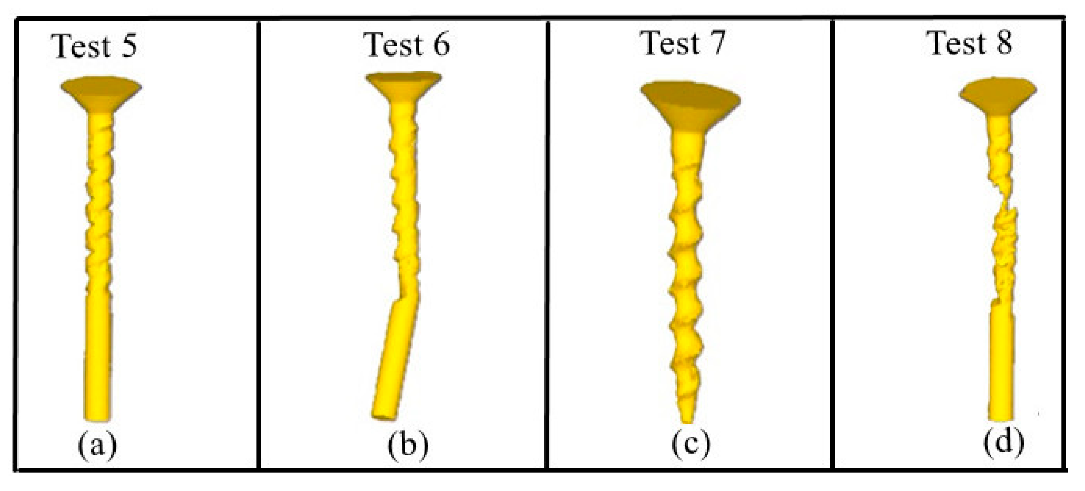
Subsequently, the die plate spacing was fine-tuned to further analyze its impact on the thread forming process. According to the simulation conditions in Tests 5 to 8 (Table 1), the distance between the die plates was gradually reduced, and the resulting thread rolling behavior was observed. In Test 5, with a slightly smaller die plate spacing than in Test 4, the simulation (Figure 17a) showed that the thread began to form gradually at the initial stage of rolling, with thread depth continuing to increase as deformation progressed. The reduced spacing concentrated the material compression, resulting in a more pronounced thread profile, and the rolling portion exceeded three-quarters of the total travel. Although the screw tail remained incomplete, the overall forming efficiency was significantly improved, indicating that die plate spacing is a critical parameter influencing thread quality.
Figure 17.
Simulation results of the thread rolling process: (a) Test 5; (b) Test 6; (c) Test 7; (d) Test 8.
In Test 6, the die plate spacing was further reduced, resulting in the screw blank advancing almost entirely by rolling throughout the thread rolling process. The thread formed clearly with significantly increased depth; however, the tail end exhibited a bent cut shape and was still not fully severed (Figure 17b). In Test 7, with the die plate spacing reduced further, the rolling behavior remained similar to Test 6, but the screw tail was completely cut off (Figure 17c), indicating that the die plate spacing had reached an optimal compaction and shearing condition. This stage represents the first occurrence of complete tail fracture in the simulation process, providing a critical reference point.
In Test 8, the die plate spacing was further reduced, and it was observed that the screw blank was almost severed at the very beginning of the thread rolling process, preventing the subsequent formation from continuing, as shown in Figure 17d. This indicates that when the die plate spacing is too small, the screw blank experiences intense compression and shearing at initial contact, leading to uneven stress distribution. Consequently, the thread formation cannot proceed smoothly, resulting in noticeable fracture, demonstrating that excessively small die plate spacing has a destructive effect on screw forming quality.
Based on the above simulation results, although the final screw threads were not perfectly formed, it can be inferred that the die spacing used in Test 7 represents an optimal range. This spacing enables complete thread rolling and tail-end cutting while maintaining an efficient and stable forming process. Therefore, these spacing values provide critical reference for the installation and adjustment of dies in the future operation of the novel thread rolling machine.
5.2. Thread Rolling Experiments of the Novel Thread Rolling Machine
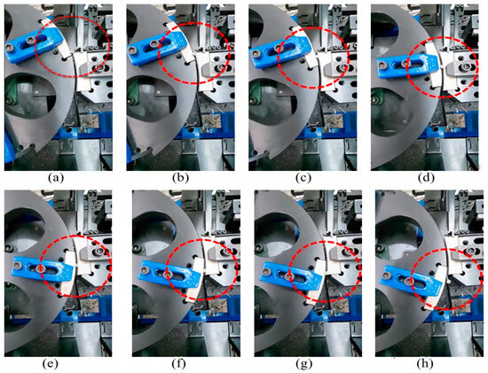
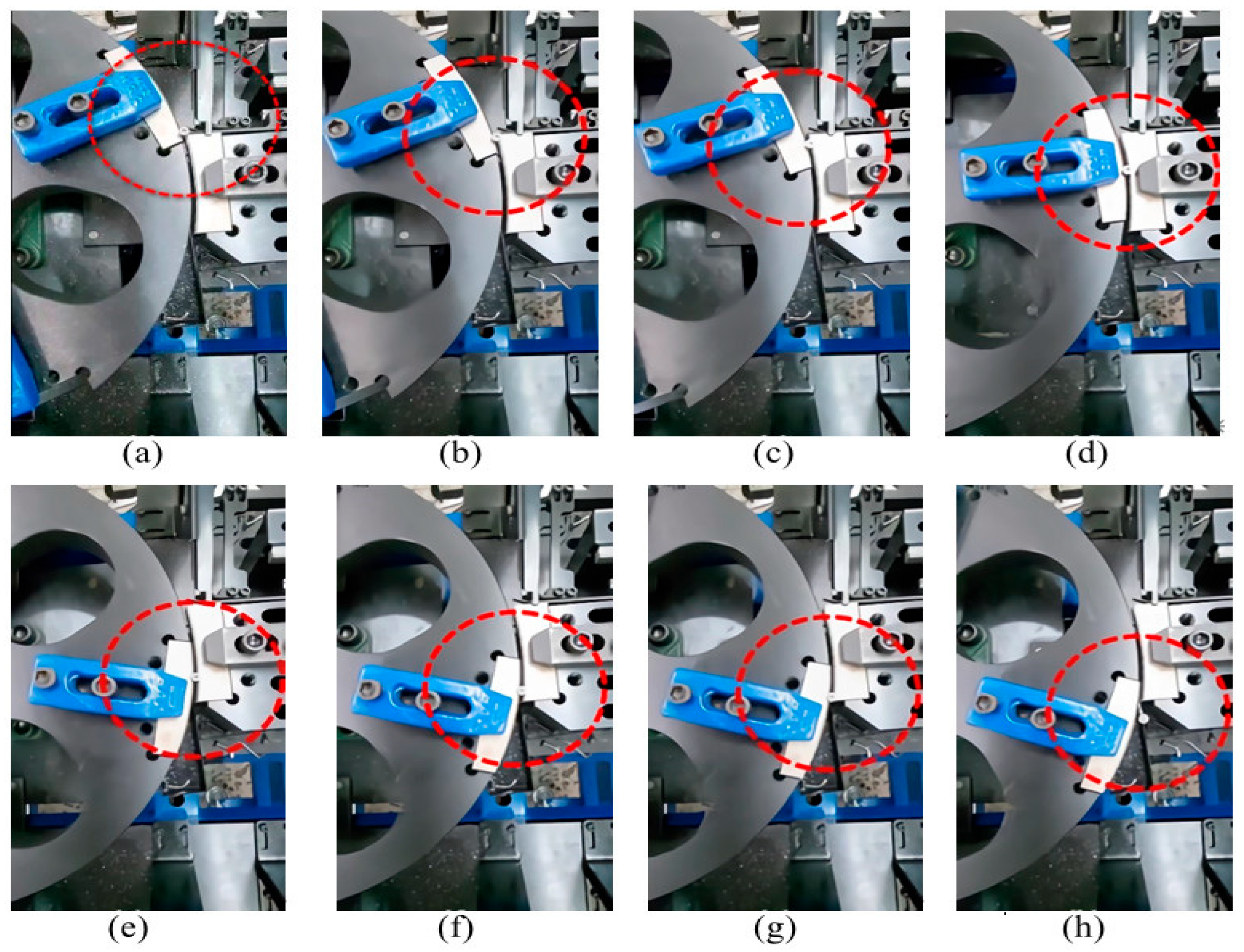
After the novel thread rolling machine was fully fabricated and assembled, its complete operational workflow is illustrated in Figure 18. The figure clearly shows the sequence of each processing stage and the corresponding mechanism configuration, presenting the entire screw thread rolling process.
Figure 18.
Complete sequence of the screw thread rolling experiment: (a) initial position; (b) feed completion; (c) rolling initiation; (d) preliminary forming; (e) final forming; (f) tail forming; (g) rolling completion; (h) screw ejection.
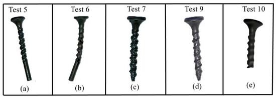
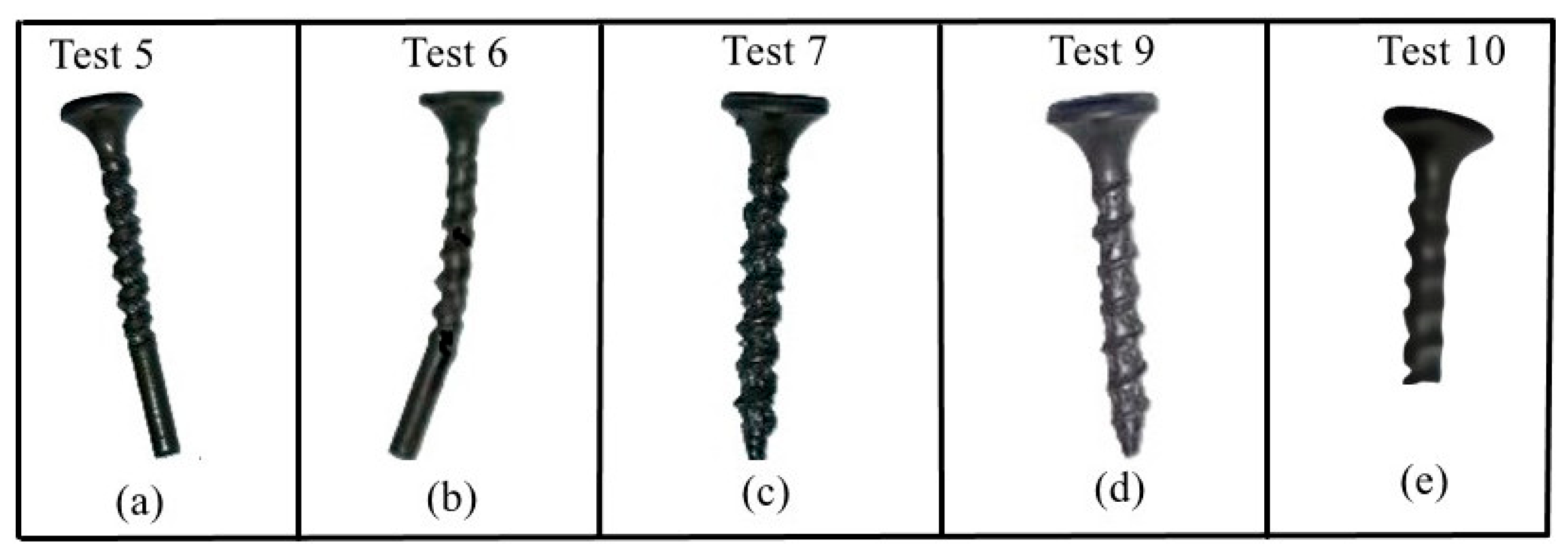
Based on the simulation results presented in Section 5.1, it was evident that the die plate spacing is a critical factor affecting the quality of the finished screw. The novel thread rolling machine was designed by referencing these different spacing conditions and implementing them in the physical device. Using the relative geometric spacing defined in Test 5 (Table 1), the die plate distance was precisely adjusted in the machine, and a physical thread rolling experiment was conducted. The results showed that the screw blank successfully developed a distinct thread profile during rolling, although the screw tip had not fully formed into a pointed end nor been completely severed, as shown in Figure 19a. The overall appearance closely matched the simulation results of Test 5 (Figure 17a), with consistent thread profile, depth, and tip deformation. Subsequently, the die plate spacing was adjusted according to the parameters of Test 6, and another physical rolling trial was performed. In this experiment, the screw thread structure exhibited significant changes: the overall appearance became more three-dimensional, the thread depth increased noticeably, and the screw tip showed clear cutting and bending deformation, indicating effective tail-end shearing by the die plate. These features were highly consistent with the simulation results, as shown in Figure 19b. When the spacing was set according to Test 7, the resulting threads became more pronounced and the overall structure approached completeness, although the pitch between adjacent threads was still not entirely clear (Figure 19c). At this stage, the screw tip was fully severed, forming a completely separated product, with an appearance almost identical to the simulation in Figure 17c. To further improve pitch clarity and uniformity, the die plate spacing was slightly reduced to the value of Test 9, and the rolling experiment was repeated. The resulting screws exhibited more distinct thread profiles, uniform pitch distribution, and fully formed tips, producing the final screws with clearly defined thread characteristics, as shown in Figure 19d. When the spacing was further reduced to Test 10, the screws were cut during the rolling process (Figure 19e).
Figure 19.
Experimental results of the thread rolling process: (a) Test 5; (b) Test 6; (c) Test 7; (d) Test 9; (e) Test 10.
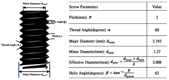
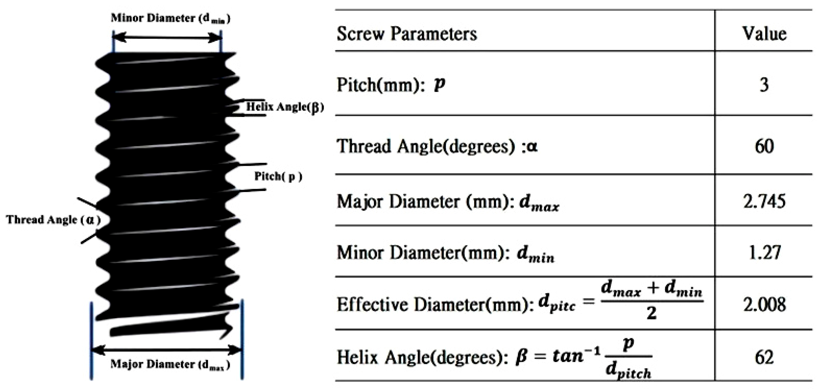
Similarly, the die spacing was set to the Test 9 condition and applied to the overall rotational thread rolling experiments on the novel machine. Owing to the design characteristics of the new mechanism, four screw products are formed simultaneously in each full rotation. Accordingly, three consecutive complete rotations were conducted in this experiment, yielding a total of twelve screw specimens. The measured parameters of these screws were then analyzed and compared with those of standard screws produced by the CPR6 thread rolling machine (Figure 20).
Figure 20.
Parameters of standard screws manufactured using linear dies.
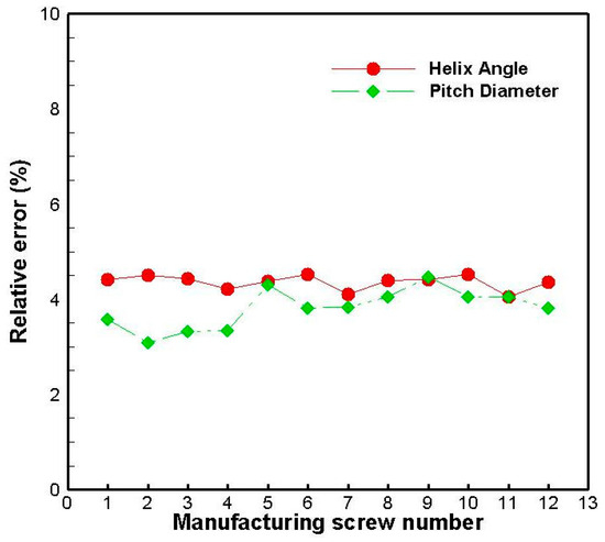
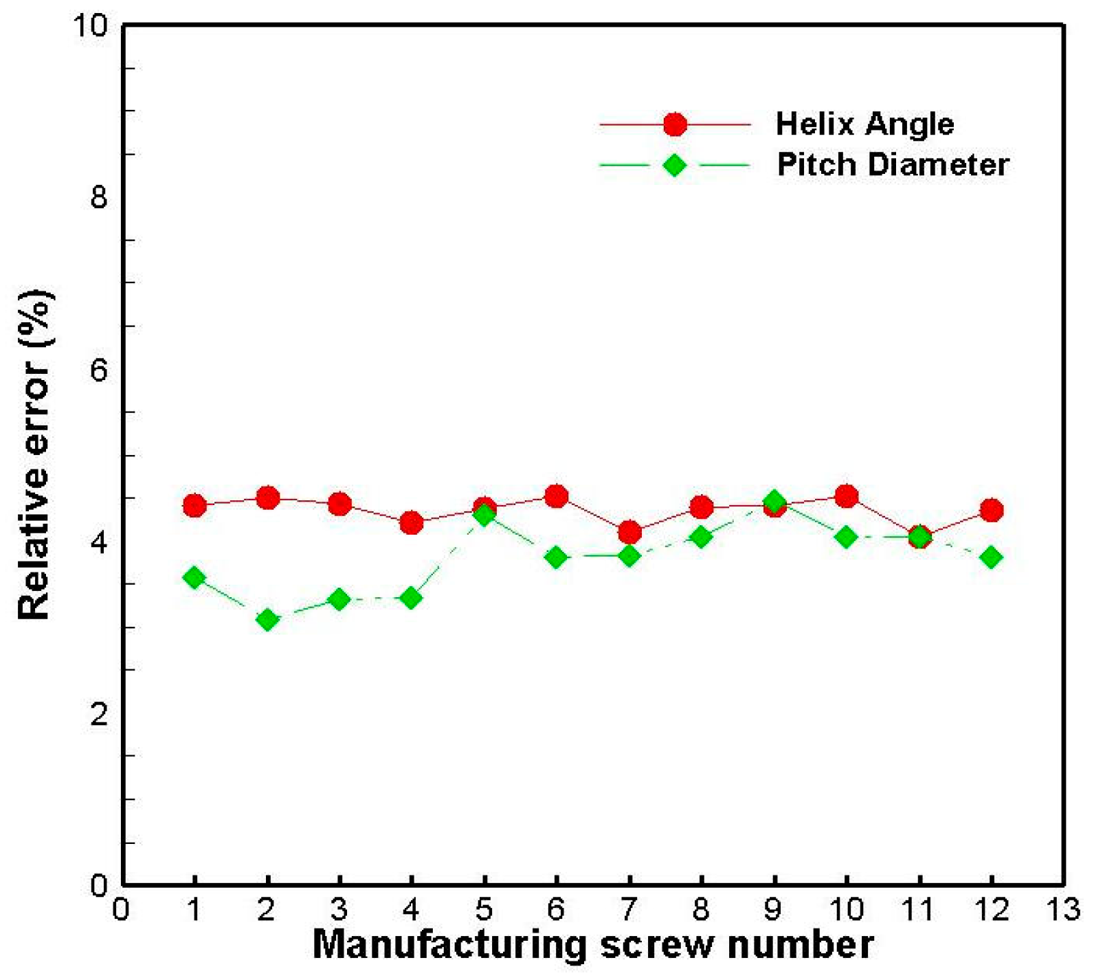
Experimental results show that the thread pitch and thread angle of the produced screws are 3 mm and 60°, respectively, matching the specifications of standard screws, indicating good consistency in thread forming accuracy. For pitch diameter and helix angle, the measured values were compared to target specifications using relative error (the ratio of the difference between measured and target values to the target value). The results show that the relative errors for both pitch diameter and helix angle remain within 5%, as shown in Figure 21. Although the deviations are small, slight geometric discrepancies were observed, primarily due to variations in die geometry and load distribution during the thread rolling process, leading to minor differences between the formed threads and target specifications.
Figure 21.
Relative errors of pitch diameter and helix angle for the experimentally produced screws.
The primary cause of the discrepancies lies in the use of dies based on the original straight-die geometry. The novel thread rolling machine adopts a sector-shaped structure, but due to practical constraints such as mechanism realization, cost control, and manufacturing lead time, only the external profile of the dies was modified to a curved shape, while the original tooth-surface geometry was preserved. Although this approach maintains the essential characteristics of the die tooth profile, the change in external geometry alters the effective tooth length and the contact path. This, in turn, affects the force distribution and the forming trajectory of the screw blank during the rolling process.
As a result, slight deviations in the helix angle and pitch diameter occurred, leading to small discrepancies between the experimental results and the theoretical model. Nevertheless, the experimental results demonstrate that the new thread rolling machine meets the expected design goals in terms of structural configuration, motion accuracy, and forming stability. The machine efficiently forms multiple screws simultaneously with stable performance, and the experimental outcomes align closely with simulation analyses. This confirms that the proposed system is controllable and reliable in practical operation.
The thread forming profile and parameter values for the traditional thread rolling machine are shown in Figure 20. In this study, the newly developed thread rolling machine uses a straight thread plate that is directly bent without redesigning the thread surface. This approach saves production time and testing costs. Consequently, the forming of four screws in a single cycle may show slight deviations from the parameters in Figure 21, which is expected.
As shown in Figure 21, 12 screws can be processed in three cycles. The deviation in the Helix Angle and Pitch Diameter is minimal, with a small error range for all 12 screws. This indicates the satisfactory processing stability of the proposed mechanism. The minor variations observed fall within acceptable limits, showing the system’s efficiency and stability in multi-piece forming. These slight discrepancies are mainly due to the variations in die geometry and load distribution during the rolling process, as the dies used were based on the original straight-die design without further refinement for this specific application.
These results further confirm that the new thread rolling machine can produce screws with consistent dimensional accuracy, demonstrating its potential for high-volume production while maintaining cost efficiency.
6. Conclusions
The main conclusions of this study are summarized as follows:
- (1)
- A novel sector-type rotational thread rolling machine was successfully proposed, designed, and experimentally validated through an integrated framework combining theoretical modeling, numerical simulation, and prototype testing. Compared with conventional linear reciprocating thread rolling machines, the proposed mechanism demonstrates significant advantages in structural compactness, reduced inertia effects, improved motion controllability, and enhanced parameter adjustability. In particular, the ability to perform simultaneous multi-workpiece forming within a single rotational cycle represents a substantial improvement in production efficiency and process flexibility, making the system highly suitable for modern high-throughput screw manufacturing environments.
- (2)
- Numerical simulations revealed that the friction coefficient and die plate spacing are the dominant parameters governing material flow behavior, thread formation quality, and rolling stability. A friction coefficient of 0.8 was identified as the critical condition that ensures continuous and stable plastic flow, preventing slippage and insufficient deformation during the rolling process. Furthermore, die spacing was found to strongly influence thread completeness, tail separation timing, and the overall rolling ratio. Among the evaluated simulation cases, the Test 7 configuration achieved complete tail separation and the clearest thread profile, providing a reliable and practical reference for machine parameter configuration and die installation.
- (3)
- Experimental validation confirmed the mechanical feasibility, coordinated motion performance, and operational stability of the proposed system. After optimizing the die spacing based on simulation results, the formed screws exhibited strong agreement with numerical predictions in terms of thread depth, pitch formation, and tail-end geometry. The consistency between simulation and experimental observations verifies the reliability of the adopted modeling approach and demonstrates the effectiveness of the proposed design methodology.
- (4)
- Under the Test 9 configuration, stable simultaneous forming of four screws within a single rotational cycle was successfully achieved. The measured pitch and flank angle met the target specifications, while the deviations in pitch diameter and helix angle were maintained within 5%. These results confirm the machining accuracy, structural reliability, and practical applicability of the proposed rotational rolling mechanism for precision screw production.
- (5)
- Overall, the proposed mechanism provides a feasible, stable, and high-efficiency solution for next-generation thread rolling equipment. The compact architecture and improved controllability also offer potential advantages in factory layout optimization and automation integration.
Future work will focus on further improving the system from structural, dynamic, and intelligent control perspectives. Planned research includes the development of fully geometry-matched curved dies, detailed investigations of torque fluctuations and vibration behavior under high-speed operation, integration of real-time sensing and machine vision for closed-loop control, exploration of data-driven adaptive parameter optimization, and comprehensive evaluation of energy consumption, tool wear, and productivity under real industrial operating conditions.
Author Contributions
Conceptualization, C.-C.L. and C.-S.L.; Methodology, C.-C.L., M.-N.C. and C.-S.L.; Software, C.-C.L. and M.-N.C.; Validation, C.-C.L., M.-N.C. and C.-S.L.; Formal analysis, C.-C.L. and C.-S.L.; Investigation, C.-C.L., M.-N.C. and C.-S.L.; Resources, C.-C.L., M.-N.C. and C.-S.L.; Data curation, C.-C.L., M.-N.C. and C.-S.L.; Writing—original draft, C.-C.L.; Writing—review & editing, C.-C.L., M.-N.C. and C.-S.L.; Visualization, C.-C.L.; Funding acquisition, M.-N.C. All authors have read and agreed to the published version of the manuscript.
Funding
This work was supported by Guangdong Basic and Applied Basic Research Foundation and Guangdong Soft Science Foundation, China, under Grant 2024A0505050043.
Data Availability Statement
The original contributions presented in this study are included in the article. Further inquiries can be directed to the corresponding authors.
Conflicts of Interest
The authors declare no conflict of interest.
References
- Nastasyuk, I.G.; Glazov, Y.G. Rolling of inside threads in plastic materials. Chem. Petrol. Eng. 1977, 13, 632–634. [Google Scholar] [CrossRef] [Scilit]
- Li, Y.Y.; Zhao, S.D. Research on thread forming process of extrusion tapping of internal thread. Appl. Mech. Mater. 2011, 80, 631–637. [Google Scholar] [CrossRef] [Scilit]
- Ryabov, A.A.; Kukanov, S.S.; Strelets, D.Y.; Trifonov, R.D. Dynamic deformation and rupture of fastening elements. J. Braz. Soc. Mech. Sci. Eng. 2022, 44, 88. [Google Scholar] [CrossRef] [Scilit]
- Wan, N.; He, Q.; Jiang, Y.; Zhou, H.; Fu, B. Numerical and experimental investigation of the influence of the machining parameters on residual stress distribution of internal thread cold extrusion. CIRP J. Manuf. Sci. Technol. 2023, 40, 142–154. [Google Scholar] [CrossRef] [Scilit]
- Bhatt, R.J.; Raval, H.K. Influence of operating variables during flow forming process. Procedia CIRP 2016, 55, 146–151. [Google Scholar] [CrossRef] [Scilit]
- Tarasov, D.; Konovalov, V.; Zaitsev, V.; Rodionov, Y. Mathematical modeling of the stress–strain state of flexible threads with regard to plastic deformations. J. Phys. Conf. Ser. 2018, 1084, 012008. [Google Scholar] [CrossRef] [Scilit]
- Gong, F.; Swain, P.; Kadirkamanathan, S.; Hepworth, C.; Laufer, J.; Shelton, J.; Mills, T. Cutting thread at flexible endoscopy. Gastrointest. Endosc. 1996, 44, 667–674. [Google Scholar] [CrossRef] [Scilit] [PubMed]
- Ulbricht, V.; Franeck, J.; Schirmacher, F.; Offermann, P. Numerical investigations for cutting of wires and threads. AUTEX Res. J. 2003, 3, 9–15. [Google Scholar] [CrossRef] [Scilit]
- Akyildiz, H.K.; Livatyali, H. Prediction and experimental analysis of cutting forces during machining of precision external threads. Mach. Sci. Technol. 2011, 15, 485–506. [Google Scholar] [CrossRef] [Scilit]
- Khostikoev, M.Z.; Timiryazev, V.A.; Orlov, E.M. Control of the machining precision in thread cutting. Russ. Eng. Res. 2018, 38, 1022–1025. [Google Scholar] [CrossRef] [Scilit]
- Zhang, Y.; Hu, Z.; Guo, L. Study on a new forming method—Thread rolling by crystal plasticity finite element simulation. Metals 2021, 11, 503. [Google Scholar] [CrossRef] [Scilit]
- Zhang, S.; Zhang, D.; Wang, Y.; Zhu, Q.; Zhao, S.; Luo, W. The planetary rolling process of forming the internal thread. Int. J. Adv. Manuf. Technol. 2020, 107, 3543–3551. [Google Scholar] [CrossRef] [Scilit]
- Lipton, J.I.; Lipson, H. 3D printing variable stiffness foams using viscous thread instability. Sci. Rep. 2016, 6, 29996. [Google Scholar] [CrossRef] [Scilit]
- Nefelov, I.S.; Baurova, N.I. Formation of threaded surfaces in the components produced by 3D printing. Russ. Metall. 2017, 13, 1158–1160. [Google Scholar] [CrossRef] [Scilit]
- Farniev, A.; Novikov, P.; Sidorov, D.; Falaleev, A. Research of the accuracy of internal threads formed by FDM technology and additionally processed with tapers. In AIP Conference Proceedings; AIP Publishing: Melville, NY, USA, 2022; Volume 2503, p. 070020. [Google Scholar]
- Budzik, G.; Dziubek, T.; Kawalec, A.; Turek, P.; Bazan, A.; Dębski, M.; Józwik, J.; Poliński, P.; Kiełbicki, M.; Kochmański, Ł.; et al. Geometrical accuracy of threaded elements manufacture by 3D printing process. Adv. Sci. Technol. Res. J. 2023, 17, 35–45. [Google Scholar] [CrossRef] [Scilit] [PubMed]
- Rizea, A.D.; Anghel, D.C.; Banica, C.F. Contributions to increasing the quality of outer threads obtained through 3D printing. Acta Tech. Napoc. Appl. Math. Mech. Eng. 2023, 66, 399–408. [Google Scholar]
- Blazewicz, S.; Chlopek, J.; Litak, A.; Wajler, C.; Staszkow, E. Experimental study of mechanical properties of composite carbon screws. Biomaterials 1997, 18, 437–439. [Google Scholar] [CrossRef] [Scilit] [PubMed]
- Tzur, A.E.; Goodship, E.; Maltz, L.; Oron, U.; Steinman, A. Enhancement of bone apposition to stainless steel cortical screws by surface modification using heat treatment. J. Orthop. Trauma 1998, 12, 504–509. [Google Scholar] [CrossRef] [Scilit]
- Ristic, M.; Vasovic, I.; Alil, A.; Obradovic, J.; Prokic-Cvetkovic, R. Failure analysis of carbon steel screws under service in corrosive environments. J. Balk. Tribol. Assoc. 2018, 24, 173. [Google Scholar]
- Król, P.A.; Wachowski, M. Effect of fire temperature and exposure time on high-strength steel bolts microstructure and residual mechanical properties. Materials 2021, 14, 3116. [Google Scholar] [CrossRef] [Scilit]
- Wiewiórowska, S.; Siemiński, M.; Śleboda, T.; Łukaszek-Sołek, A.; Dyl, T.; Koczurkiewicz, B. Determination of two-stage heat treatment parameters to obtain TRIP structure in low-alloy carbon steel wires. Materials 2022, 15, 8965. [Google Scholar] [CrossRef] [Scilit]
- Jadon, V.K.; Verma, S. Analysis and Design of Machine Elements; IK International: New Delhi, India, 2010. [Google Scholar]
- Rosato, D.V. Extruding Plastics: A Practical Processing Handbook; Springer: New York, NY, USA, 2013. [Google Scholar]
- Abeykoon, C.; Martin, P.J.; Li, K.; Kelly, A.L. Dynamic modelling of die melt temperature profile in polymer extrusion. Appl. Math. Model. 2014, 38, 1224–1236. [Google Scholar] [CrossRef] [Scilit]
- Lahoti, G.D.; Pauskar, P.M. Flat, bar, and shape rolling. In Metalworking: Bulk Forming; ASM International: Materials Park, OH, USA, 2005; pp. 459–479. [Google Scholar]
- Widmaier, T. Optimisation of the Roll Geometry for Production Conditions. Ph.D. Thesis, Aalto University, Espoo, Finland, 2012. [Google Scholar]
- Brecher, C.; Eßer, B.; Falker, J.; Kneer, F.; Fey, M. Modelling of ball screw drives rolling element contact characteristics. CIRP Ann. 2018, 67, 409–412. [Google Scholar] [CrossRef] [Scilit]
- Bloch, H.P.; Geitner, F.K. Practical Machinery Management for Process Plants; Elsevier: Houston, TX, USA, 1997; Volume 2. [Google Scholar]
- Sağlam, H.; Kuş, R. Performance of internal thread rolling head and the mechanical properties of rolled thread. In Proceedings of the 6th International Advanced Technologies Symposium (IATS’11), Elazığ, Turkey, 16–18 May 2011; pp. 16–18. [Google Scholar]
- Zhdanov, A.V.; Morozov, V.V. Theoretical study of load distribution on threads for roller screw mechanisms. Procedia Eng. 2016, 150, 992–999. [Google Scholar] [CrossRef] [Scilit]
- Brandão, G.L.; Silva, P.M.D.C.; Freitas, S.A.; Pereira, R.B.D.; Lauro, C.H.; Brandão, L.C. State of the art on internal thread manufacturing: A review. Int. J. Adv. Manuf. Technol. 2020, 110, 3445–3465. [Google Scholar] [CrossRef] [Scilit]
- Yacu, W. Extruder screw, barrel, and die assembly: General design principles. In Extrusion Cooking; Woodhead Publishing: Cambridge, UK, 2020; pp. 73–117. [Google Scholar]
- Cheng, Y.-M. System for real-time measurement and monitoring of forging force of screw-forming machine. Sens. Mater. 2021, 33, 3957–3969. [Google Scholar] [CrossRef] [Scilit]
- Zhang, D.W.; Li, D.H.; Liu, B.K.; Yu, Z.C.; Zhao, S.D. Investigation and implementation for forming lead screw by through-feed rolling process with active rotation. J. Manuf. Process. 2022, 82, 96–112. [Google Scholar] [CrossRef] [Scilit]
- Amano, S.; Shinbutsu, T.; Okimoto, Y.; Takemasu, T.; Kuwabara, T. Optimization of anti-loosening bolt based on double thread mechanism. Heliyon 2024, 10, e28631. [Google Scholar] [CrossRef] [Scilit]
- Wang, Y.; Xiong, L.; Feng, D.; Liu, X.; Zhao, S. Research progress on manufacturing of screw-shaped parts in screw compressors. Appl. Sci. 2024, 14, 1945. [Google Scholar] [CrossRef] [Scilit]
- Domblesky, J.P.; Feng, F. A parametric study of process parameters in external thread rolling. J. Mater. Process. Technol. 2002, 121, 341–349. [Google Scholar] [CrossRef] [Scilit]
- Zhang, D.W.; Zhao, S.D.; Ou, H. Analysis of motion between rolling die and workpiece in thread rolling with round dies. Mech. Mach. Theory 2016, 105, 471–494. [Google Scholar] [CrossRef] [Scilit]
- Dieter, G.E.; Kuhn, H.A.; Semiatin, S.L. (Eds.) Handbook of Workability and Process Design; ASM International: Materials Park, OH, USA, 2003. [Google Scholar]
- Hosford, W.F.; Caddell, R.M. Metal Forming: Mechanics and Metallurgy, 4th ed.; Cambridge University Press: Cambridge, UK, 2011. [Google Scholar]
- Rojas, J.D.; Arrieta, O.; Vilanova, R. Industrial PID Controller Tuning; Springer: Berlin/Heidelberg, Germany, 2021. [Google Scholar]
- Ulusoy, S.; Bekdaş, G.; Nigdeli, S.M.; Kim, S.; Geem, Z.W. Performance of optimum tuned PID controller with different feedback strategies on active-controlled structures. Appl. Sci. 2021, 11, 1682. [Google Scholar] [CrossRef] [Scilit]
- George, T.; Ganesan, V.J.C.P. Optimal tuning of PID controller in time delay system: A review on various optimization techniques. Chem. Prod. Process Model. 2022, 17, 1–28. [Google Scholar] [CrossRef] [Scilit]
- Chandra, G.; Pandey, A. Design and analysis of biodegradable buttress threaded screws for fracture fixation in orthopedics: A finite element analysis. Biomed. Phys. Eng. Express 2021, 7, 045010. [Google Scholar] [CrossRef] [Scilit]
- He, Q.; Jiang, Y.; Jing, X.; Jiang, Y.; Zhou, H.; Fu, B. Research and optimization of process parameters for internal thread forming based on numerical simulation and experimental analysis. Materials 2022, 15, 3160. [Google Scholar] [CrossRef] [Scilit] [PubMed]
- Brutti, C.; Groth, C.; Biancolini, M.E. A fast analytical method for elastic–plastic analysis of threaded connections. Appl. Mech. 2025, 6, 42. [Google Scholar] [CrossRef] [Scilit]

Disclaimer/Publisher’s Note: The statements, opinions and data contained in all publications are solely those of the individual author(s) and contributor(s) and not of MDPI and/or the editor(s). MDPI and/or the editor(s) disclaim responsibility for any injury to people or property resulting from any ideas, methods, instructions or products referred to in the content. |
© 2026 by the authors. Licensee MDPI, Basel, Switzerland. This article is an open access article distributed under the terms and conditions of the Creative Commons Attribution (CC BY) license.