


Abstract
Traditional gear transmission involves relative sliding between mating tooth flanks, which can cause frictional losses and influence transmission efficiency, thermal response, and dynamic performance. This study compares three gear pairs: Type N (pure rolling gears with a circular-arc tooth profile in the normal section), Type T (pure rolling gears with a circular-arc tooth profile in the transverse section), and Type INV (involute helical gears). The loaded transmission error (LTE) characteristics of Type N and Type T are compared over eight helix angle conditions from 10° to 45°. Transmission efficiency and sound pressure level are experimentally evaluated for all three gear pairs over a speed range of 200–450 rpm and a load-torque range of 1–6 N·m. Infrared thermography is used to compare the thermal response of Type N and Type INV after 1 h of continuous operation at 6 N·m and input speeds of 400 and 500 rpm. The LTE comparison indicates that Type T exhibits lower peak-to-peak LTE than Type N over the investigated helix angle range, with non-monotonic variations for both types. At 400 rpm and 6 N·m, the transmission efficiencies of Type N, Type T, and Type INV are 98.795%, 98.305%, and 96.204%, respectively, while their corresponding sound pressure levels are 74.71, 72.78, and 77.16 dB(A). Type N also exhibits a lower meshing-region temperature rise than Type INV at both thermal-test speeds. The results reveal distinct motion-transmission, energy-transmission, acoustic, and thermal characteristics among the investigated tooth-profile designs.
1. Introduction
High-performance gear transmissions are fundamental to power transmission and motion control in modern mechanical equipment and are widely used in automotive, aerospace, renewable energy, industrial robotics, and advanced manufacturing applications [1]. As mechanical equipment evolves toward higher efficiency, greater precision, lower noise, and improved reliability, gear transmission systems are required not only to ensure stable power and motion transmission but also to minimize energy losses and thermal accumulation while maintaining favorable dynamic performance [2,3]. Therefore, gear meshing characteristics are closely associated with transmission efficiency, motion transmission stability, operating temperature, and noise performance [4].
Involute gears have well-established systems for geometric design, manufacturing, and accuracy control and are among the most widely used tooth-profile forms [5]. However, except in the vicinity of the pitch point, relative sliding occurs between the mating tooth flanks of involute gears during meshing, resulting in frictional power losses and potentially causing temperature rise, wear, and scuffing [6,7]. Meanwhile, factors such as tooth-profile geometry, contact conditions, manufacturing errors, applied load, and installation conditions can affect the transmission error and dynamic response of gear systems [8]. Therefore, reducing relative sliding between tooth flanks and improving overall transmission performance have become important directions in the development of pure rolling gears [9].
Pure rolling gears reconstruct the geometric relationships of the tooth surfaces and the law of meshing motion such that the relative sliding velocity at the theoretical meshing locations approaches zero, thereby providing a new design approach for reducing sliding-related frictional losses [10]. Based on this concept, various pure rolling gears and related spatial curvilinear gear configurations have been proposed, and their geometric design, meshing characteristics, and mechanical performance have been investigated [11,12]. Among them, line gears are based on the theory of spatial conjugate-curve meshing and construct spatial contact curves by actively defining the meshing-line function, thereby providing considerable freedom in the geometric design of pure rolling gears [13,14]. Circular-arc tooth profiles feature relatively simple geometric representations and a high degree of parameterization and have also been employed in the design of pure rolling gears and related spatial curvilinear gears [15].
For helical gears, the section in which the tooth profile is defined can further alter the geometric characteristics of the spatial active tooth surface and affect tooth thickness and meshing performance [16]. Defining the circular-arc tooth profile in the normal section can avoid certain geometric constraints introduced by the spatial transformation of the tooth profile defined in the transverse section, thereby providing a new approach for the design of circular-arc tooth profiles for pure rolling under helical-gear conditions [17]. Building on this approach, the previous study established the geometric design of Type N and numerically compared Type N and Type T through tooth contact analysis, finite-element stress analysis, and loaded transmission error (LTE) analysis over eight helix angle conditions [18]. The comparison focused on contact patterns, loaded motion-transmission characteristics, and contact and bending stress performance.
However, a review of the existing literature indicates that research on pure rolling gears still has three main limitations. First, existing studies have focused primarily on gear geometric design, spatial meshing modeling, and contact analysis, while experimental evaluation of fabricated gear specimens under multiple operating conditions remains relatively limited [19]. Second, transmission efficiency, loaded transmission error, acoustic response, and thermal response characterize different aspects of gear performance; therefore, a single performance metric is insufficient to evaluate the practical transmission performance of different tooth profiles comprehensively [20,21]. Finally, although Type N and pure rolling gears with a circular-arc tooth profile in the transverse section (Type T) share the pure rolling design concept, their tooth profiles are defined in the normal and transverse sections, respectively. These different definitions produce different spatial active tooth surfaces, while their transmission performance has not yet been systematically compared under common design parameters and experimental conditions [22]. Therefore, comparing loaded motion-transmission characteristics with experimental measurements on fabricated gear specimens can provide a more comprehensive assessment of different tooth-profile forms.
The present study compares three types of gear pairs: Type N, Type T, and involute helical gears (Type INV), with Type INV serving as a conventional reference. The LTCA results reported for Type N and Type T are considered to examine the differences in loaded motion transmission [18]. The three gear pairs were fabricated under consistent conditions with respect to tooth number, transmission ratio, normal module, normal pressure angle, reference helix angle, face width, material, and target manufacturing accuracy. Transmission efficiency and acoustic response were experimentally evaluated for all three gear pairs at different rotational speeds and load torques using a common test rig. Infrared thermography was further used to compare the meshing-region surface-temperature response of Type N and Type INV under the prescribed operating conditions. Together, these evaluations provide a comparative assessment of motion transmission, energy transmission, acoustic response, and thermal response. The remainder of this paper is organized as follows. Section 2 introduces the gear geometry, the LTCA results considered, the experimental test rig, and the evaluation metrics. Section 3 presents the LTE comparison and the experimental results for transmission efficiency, acoustic response, and thermal response. Section 4 discusses the effects of tooth-profile definition on these performance characteristics and their engineering implications. Section 5 summarizes the main conclusions.
2. Materials and Methods
2.1. Previous Design and Gear Geometry
The Type N gear pair investigated in this study was developed using the previously proposed design method for pure rolling gears with a circular-arc tooth profile in the normal section. The previous study established the parametric design of the pure rolling contact curves, circular-arc tooth profile in the normal section, and spatial active tooth surfaces and verified their pure rolling meshing characteristics through tooth contact analysis. The complete theoretical derivation of the previously proposed design method is not repeated here; instead, only the geometric definitions and key parameters required for the modeling of the three gear pairs, specimen fabrication, and subsequent performance analysis are presented.
2.1.1. Contact Curve
The spatial active tooth surfaces of a pure rolling gear pair are generated from the corresponding conjugate contact curves of the pinion and gear. In this study, Type N adopts the pure rolling contact curves established in the previous study, and the three-dimensional active tooth surfaces are generated according to the corresponding spatial motion relationships. The pure rolling contact curves of the pinion and gear are given by Equations (1) and (2), respectively. The physical meanings of the relevant parameters and the coordinate definitions are consistent with those of the previously developed design model [18].
and
The definitions of all parameters are consistent with those of the previously developed design model, and the detailed parametric equations are provided in Ref. [18]. The complete theoretical derivation of the contact curves is therefore not repeated here.
2.1.2. Normal-Section Circular-Arc Tooth Profile
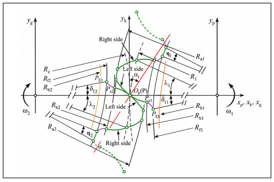
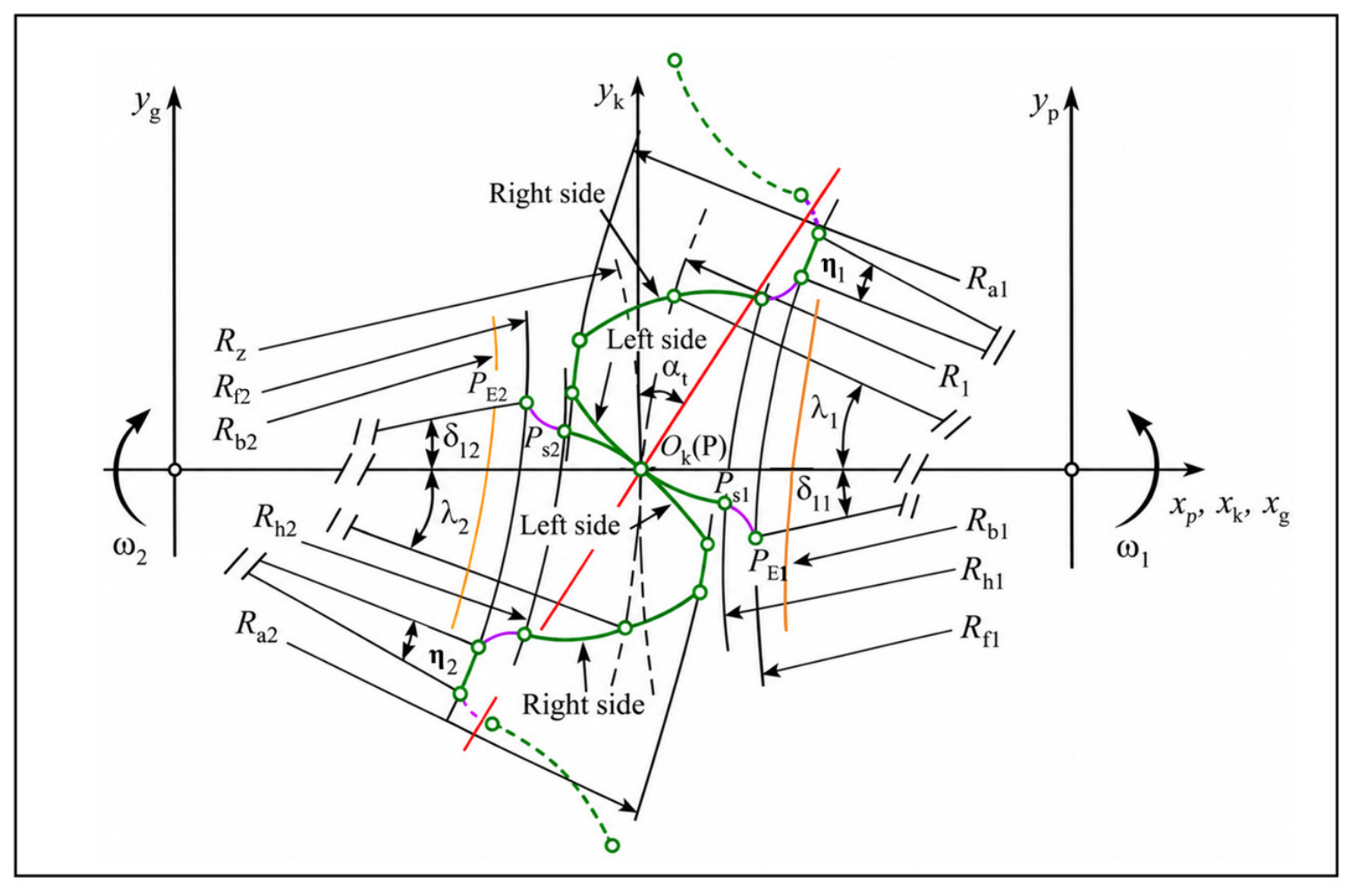
Type N defines the circular-arc tooth profile in the normal section of the gear and obtains the spatial active tooth surface through coordinate transformation. As shown in Figure 1, the complete tooth profile consists of the active circular-arc tooth profile and a fillet transition curve. The radii of curvature of the active circular-arc tooth profiles of the pinion and gear are ρa and ρb, respectively, and the root region is connected by a Hermite curve to form a continuous and complete tooth profile.
Figure 1.
Schematic of the complete tooth profile of Type N [18].
Type N and Type T employ the same circular-arc tooth-profile parameters, with the only difference being the section in which the circular-arc tooth profile is defined: Type N is defined in the normal section, whereas Type T is defined in the transverse section. The relevant parameters are listed in Table 1.
Table 1.
Circular-arc tooth-profile parameters of Type N and Type T.
2.1.3. Tooth Surface Generation
After defining the active circular-arc tooth profile, the three-dimensional active tooth surfaces are generated by spatially mapping the corresponding pure rolling contact curves of the pinion and gear. The parametric equations of the active tooth surfaces of the pinion and gear are given by Equations (3) and (4), respectively. The parameter definitions and coordinate transformation relationships are consistent with those of the previously developed design model. Type T employs the same spatial tooth-surface generation method but uses the circular-arc tooth profile defined in the transverse section as the reference; Type INV adopts the standard involute helical gear tooth profile.
and
2.1.4. Basic Geometric Parameters and Fabricated Specimens
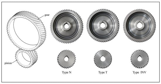
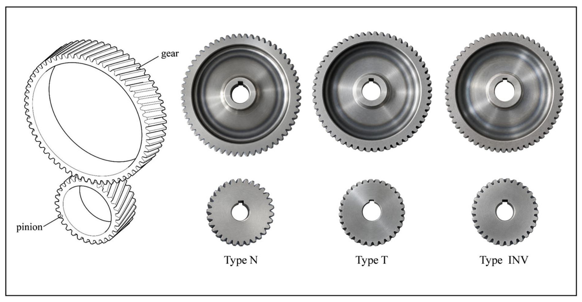
The basic geometric and manufacturing parameters of the three gear pairs are listed in Table 2. The three gear pairs were designed with the same tooth numbers, transmission ratio, normal module, normal pressure angle, reference helix angle, and face width to facilitate comparison among the different tooth-profile forms. The addendum and clearance coefficients of Type INV followed the standard involute gear design, whereas those of Type N and Type T followed the proposed pure rolling gear design. The three gear pairs were manufactured by an external subcontractor using 40Cr steel. The subcontractor performed quenching and tempering, followed by finish machining on a DMU 75 five-axis CNC machining center. Grade 6 was specified as the target manufacturing accuracy. No lead crowning or other intentional tooth-flank micro-geometry modification was applied to the fabricated specimens. The three-dimensional models and fabricated specimens are shown in Figure 2.
Table 2.
Basic geometric and manufacturing parameters of the investigated gear pairs.
Figure 2.
Three-dimensional models and fabricated specimens of the investigated gear pairs.
2.2. Numerical LTCA Model
2.2.1. Numerical Model Configuration
The LTE comparison for Type N and Type T over different helix angle conditions is taken from the previously reported LTCA analysis [18]. These results are considered here to discuss the loaded motion-transmission characteristics of the two tooth-profile definitions alongside the experimental results. The detailed finite-element model and analysis procedure are described in the cited study.
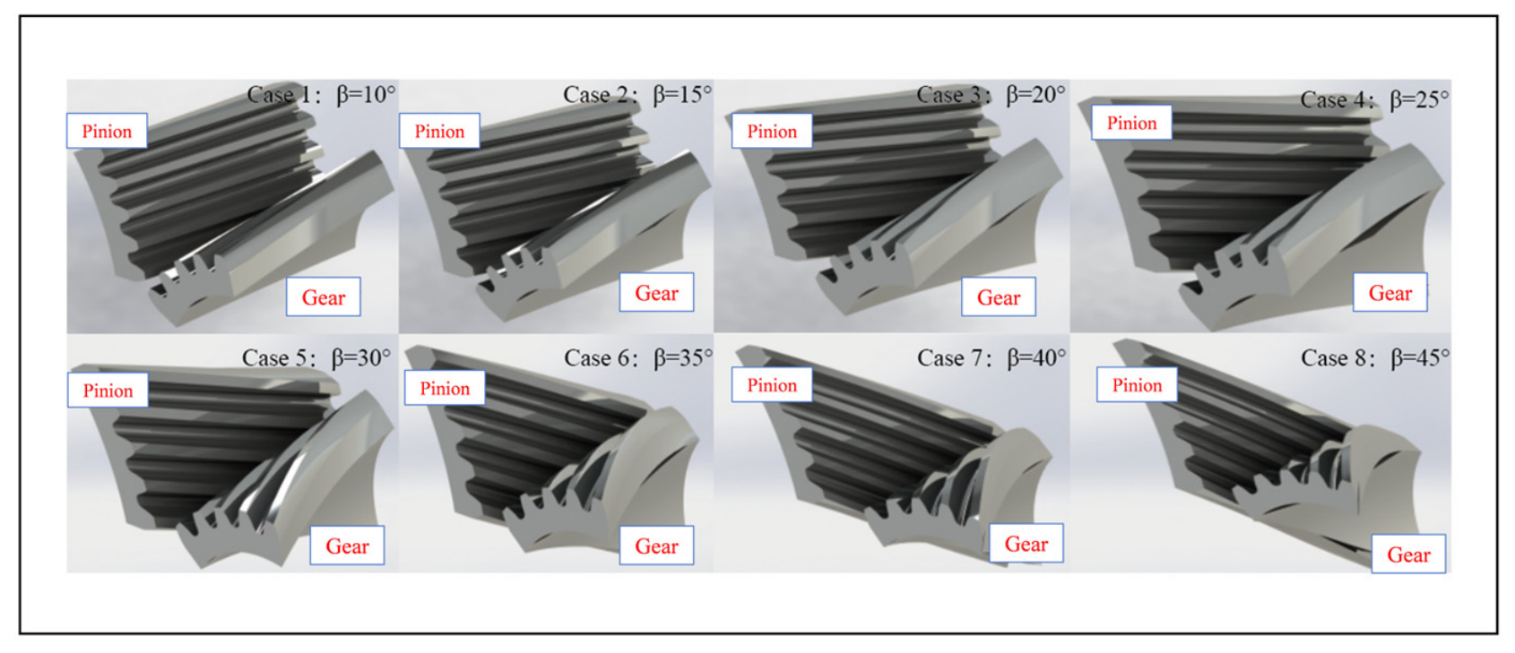
The reported LTCA comparison covers eight helix-angle cases, namely 10°, 15°, 20°, 25°, 30°, 35°, 40°, and 45°, as illustrated in Figure 3.
Figure 3.
Eight numerical LTCA cases with different helix angles.
2.2.2. Helix Angle Cases and LTE Extraction
In the reported LTCA analysis, the loaded angular-displacement responses of the pinion and gear were obtained for each helix angle condition. LTE was defined as the deviation between the actual angular-displacement relationship and the theoretical transmission relationship of the gear pair. The peak-to-peak LTE was calculated as the difference between the maximum and minimum LTE values within one transmission period [18]. The helix angle cases and their associated motion parameters and contact ratios are listed in Table 3.
Table 3.
Numerical LTCA cases for Type N and Type T.
2.3. Experimental Test Rig
A precision gear transmission test rig was employed to conduct the transmission-efficiency and acoustic-response experiments of the three investigated gear pairs, as well as the thermal-response experiments of Type N and Type INV. The test rig consisted of a driving unit, loading unit, tested gear pair, torque and speed sensors, and a data-acquisition and control system.
2.3.1. Experimental Rig Configuration
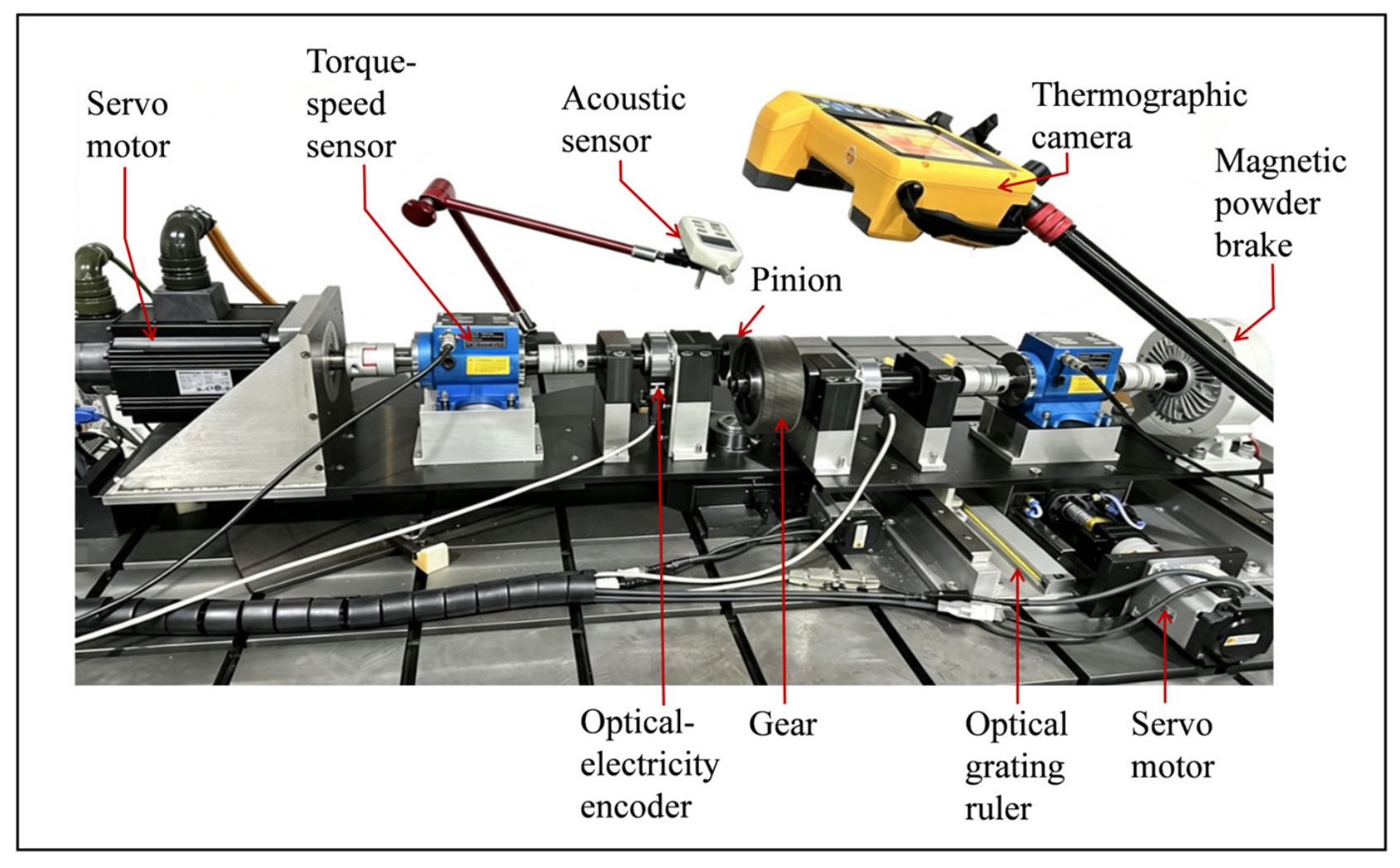
The test rig was driven by a Panasonic MSMF152L1A1 servo motor, and the output shaft was loaded using an FZ30J magnetic powder brake. Two Lanling ZJ-30A torque and speed sensors were installed on the input and output shafts, respectively. The test rig was equipped with precision center-distance and shaft-angle adjustment mechanisms, and an NT03RA200M precision rotary stage was employed to adjust the installation conditions. The main equipment and technical specifications are listed in Table 4. The overall configuration of the test rig and the arrangement of its main functional units are shown in Figure 4.
Table 4.
Specifications of the test rig and measurement instruments.
Figure 4.
Experimental test rig for gear transmission performance evaluation.
2.3.2. Measurement and Data Acquisition
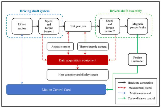
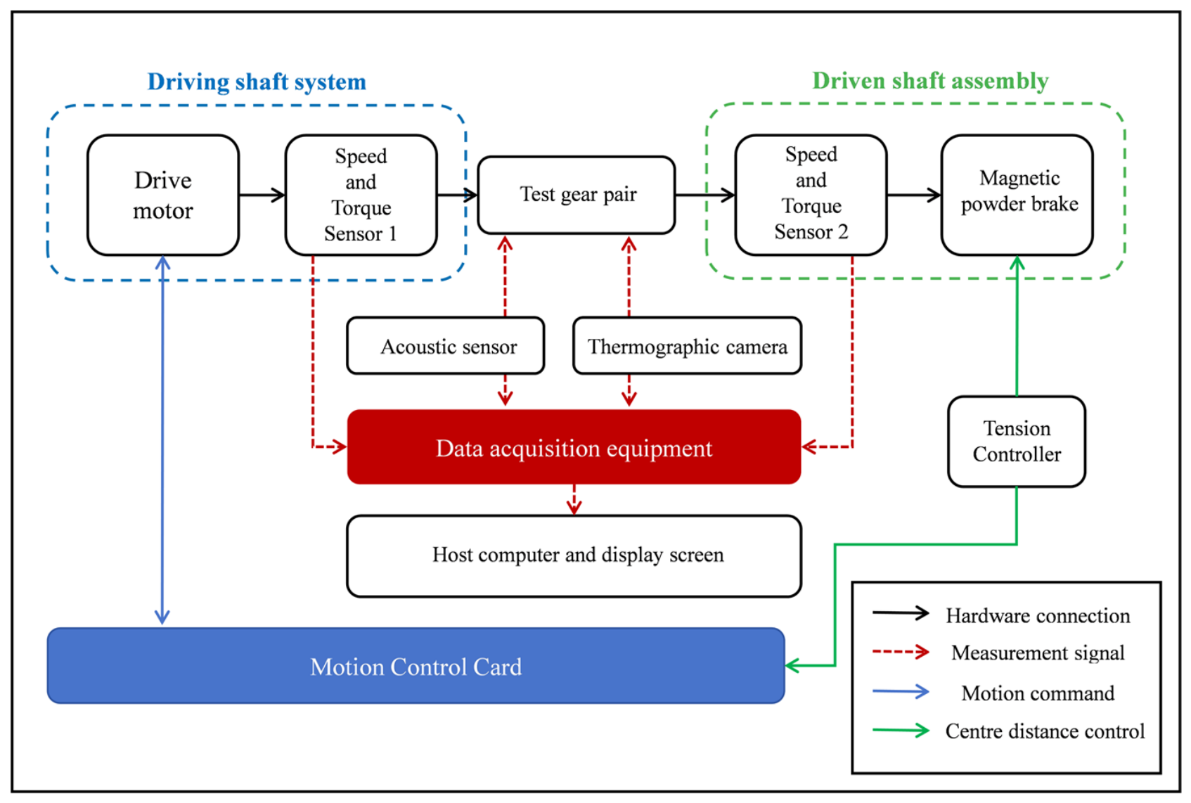
The control system consisted of an Advantech ARK-3532D industrial computer, a GTS-400-PV-PCIe-00 multi-axis motion controller, and a GT2-400-ACC2-VB-V-A expansion module. The input and output shaft torque and speed sensors were used to record the operating conditions of the test rig. Temperature and acoustic responses were measured using a Fluke TiX580 infrared thermal imaging camera and a Wensn WS1361 sound level meter, respectively. The measurement and data-acquisition arrangement is shown in Figure 5.
Figure 5.
Schematic of the measurement and data acquisition system.
2.3.3. Test-Rig Parasitic Mechanical Loss
To minimize the influence of the mechanical losses of the test rig itself on the calculation of gear transmission efficiency, the parasitic mechanical losses of the test rig were calibrated before the formal gear tests. During the calibration process, the input and output shafts were directly connected using an elastic coupling, excluding the tested gear pair from the transmission chain. The output end was still loaded by the same magnetic powder brake used in the formal experiments, and the input and output shaft speed and torque signals were collected under rotational speed and loading conditions consistent with the formal tests. The input and output mechanical powers were calculated as follows:
where T and ω represent the shaft torque and angular velocity, respectively. Under the calibrated condition without the tested gear pair, the parasitic mechanical power loss of the test rig was defined as follows:
and
During the formal gear tests, the measured input power was corrected by subtracting the parasitic mechanical losses of the test rig obtained under the corresponding calibration conditions. The corrected power loss attributed to the tested gear pair was then determined as follows:
The transmission efficiency of the gear pair was further calculated based on the corrected input mechanical power:
The measured parasitic mechanical losses under test conditions corresponding to the formal experiments were used for correction to reduce the influence of the mechanical losses of the test rig itself on the evaluation of gear pair transmission efficiency.
2.4. Test and Analysis Conditions
To facilitate direct comparison among the different tooth-profile designs, 400 rpm and 6 N·m were selected as the representative operating condition. This condition corresponds to the maximum torque used in the transmission-efficiency tests and is consistent with the thermal tests. All three gear pairs were tested under dry-running conditions without additional lubrication. The same test rig, installation conditions, measurement positions, and measurement procedures were used across the three gear pairs to maintain consistency. The test matrix is provided in Table 5.
Table 5.
Test and analysis matrix for the investigated gear pairs.
- (1)
- Transmission efficiency. Transmission-efficiency experiments were conducted on Type N, Type T, and Type INV gear pairs. The input rotational speeds were set to 200, 250, 300, 350, 400, and 450 rpm, and the applied torques were set to 1, 2, 3, 4, 5, and 6 N·m, resulting in 36 rotational speed–torque combinations. All three gear pairs were tested using the same test rig, loading method, and measurement system. Transmission efficiency was calculated from the mechanical power after correcting for test-rig parasitic losses.
- (2)
- Acoustic response. Acoustic experiments were conducted under the same 36 speed–torque conditions as the transmission-efficiency tests. Sound pressure level was measured using a Wensn WS1361 sound level meter with A-weighting and the Slow time-response mode. After the gear pair reached a stable operating condition, the average sound pressure level over a continuous 30 s interval was recorded. All three gear pairs were evaluated using the same measurement position and distance under consistent environmental conditions. Before the acoustic tests, the background sound pressure level was measured as 44.5 dB(A). The background level was not directly subtracted from the measured levels in decibel units; instead, the sound pressure levels were compared under the same experimental environment and measurement conditions.
- (3)
- Thermal response. Thermal-response experiments were conducted on Type N and Type INV at a torque of 6 N·m and input speeds of 400 and 500 rpm. Each gear pair was operated continuously for 1 h. The surface temperature in the gear meshing region was recorded using a Fluke TiX580 infrared thermal imaging camera. The emissivity was set to the thermal imager’s system-default value of 0.98, as documented in the experimental records, and the reflected-temperature compensation was set to 0 °C. The same emissivity setting and measurement configuration were maintained throughout the thermal tests to ensure consistency in data acquisition and processing for the two gear pairs. Both tested gear pairs were made of 40Cr steel and fabricated using the same general manufacturing process, allowing their thermal responses to be compared under nominally comparable measurement conditions. The area-averaged surface temperature was extracted from the predefined meshing region [23]. The same measurement region and data-extraction procedure were used for both gear pairs.
2.5. Evaluation Metrics
- (1)
- Loaded transmission error. LTE was used to characterize the motion transmission fluctuation of the gear pair under loaded conditions. It was calculated from the actual angular displacements of the pinion and gear according to their theoretical transmission relationship. The peak-to-peak value of LTE within one transmission cycle was adopted as the evaluation indicator:where LTEmax and LTEmin represent the maximum and minimum values of the LTE within one transmission cycle, respectively.
- (2)
- Transmission efficiency. The transmission efficiency of the gear pair was calculated using Equation (9), which evaluates the efficiency based on the input and output mechanical powers after correcting for the parasitic mechanical losses of the test rig.
- (3)
- Acoustic response. The sound pressure level (SPL) was adopted as the acoustic response indicator to compare the acoustic characteristics of the three investigated gear pairs under identical test conditions.
- (4)
- Thermal response. The surface temperature rise relative to ambient temperature in the gear meshing region was defined as the difference between the area-averaged surface temperature measured after continuous operation for 1 h and the ambient temperature before the experiment:where T1h represents the area-averaged surface temperature within the predefined meshing region after continuous operation for 1 h, and Tamb represents the ambient temperature before the experiment.
For the comparison between Type N and Type INV, the temperature rise reduction ratio of Type N relative to Type INV was further defined as follows:
This indicator was used to compare the differences in thermal response between the two gear pairs under identical loading and rotational speed conditions.
3. Results
This section presents the LTE comparison for Type N and Type T and the experimental results for the fabricated gear specimens. Transmission efficiency and acoustic response are compared for all three gear pairs under different rotational speeds and load torques, followed by the thermal-response comparison between Type N and Type INV under the prescribed operating conditions.
3.1. Numerical Loaded Transmission Error
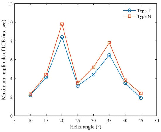
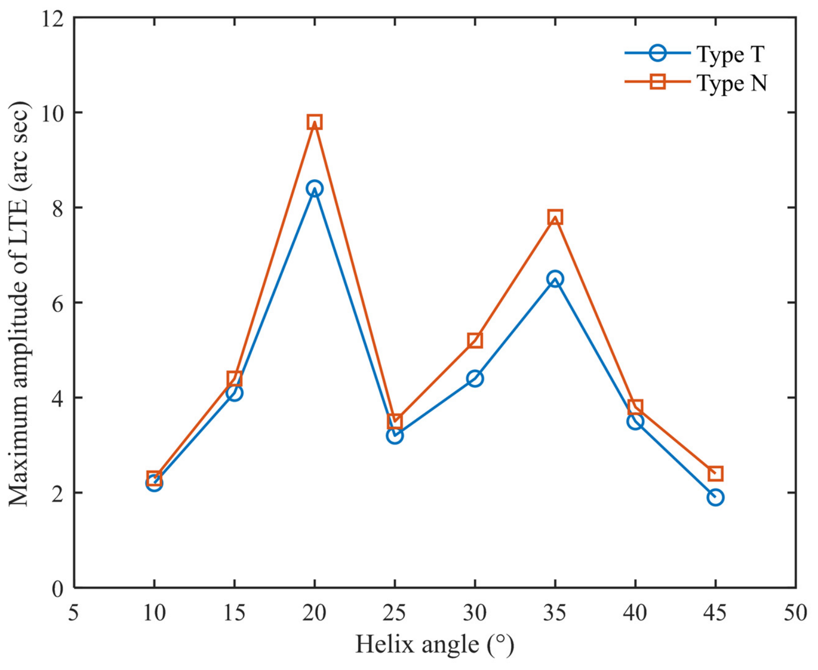
Figure 6 presents the peak-to-peak LTE comparison for Type N and Type T over the investigated helix angle range of 10–45°.
Figure 6.
Peak-to-peak loaded transmission error of Type N and Type T at different helix angles [18].
The peak-to-peak loaded transmission error of both Type N and Type T exhibits a pronounced non-monotonic variation with helix angle. Type T consistently shows a lower peak-to-peak loaded transmission error than Type N at all investigated helix angles. Both gear pairs exhibit relatively high LTE values at around 20°, whereas the values reach relatively low levels within the investigated range at 45°. Overall, Type T consistently exhibits lower loaded motion transmission fluctuation than Type N over the helix angle range of 10–45°.
3.2. Transmission Efficiency
Transmission efficiency tests were conducted for Type N, Type T, and Type INV over a rotational speed range of 200–450 rpm and a load torque range of 1–6 N·m. The three gear pairs were tested using the same test rig, loading method, and measurement system, and the transmission efficiency was calculated from the input and output mechanical power after correction for the test-rig parasitic mechanical loss.
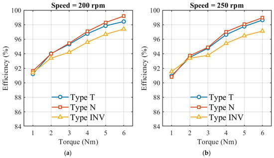
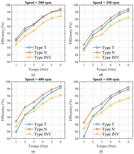
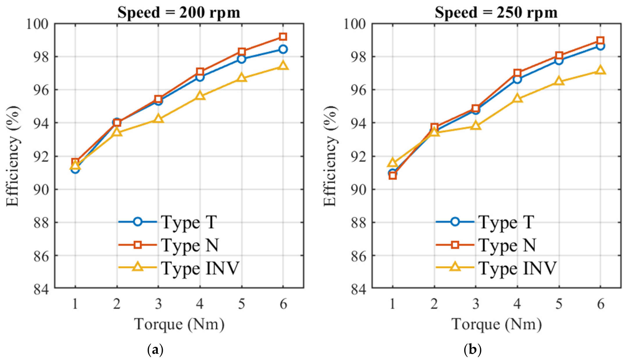
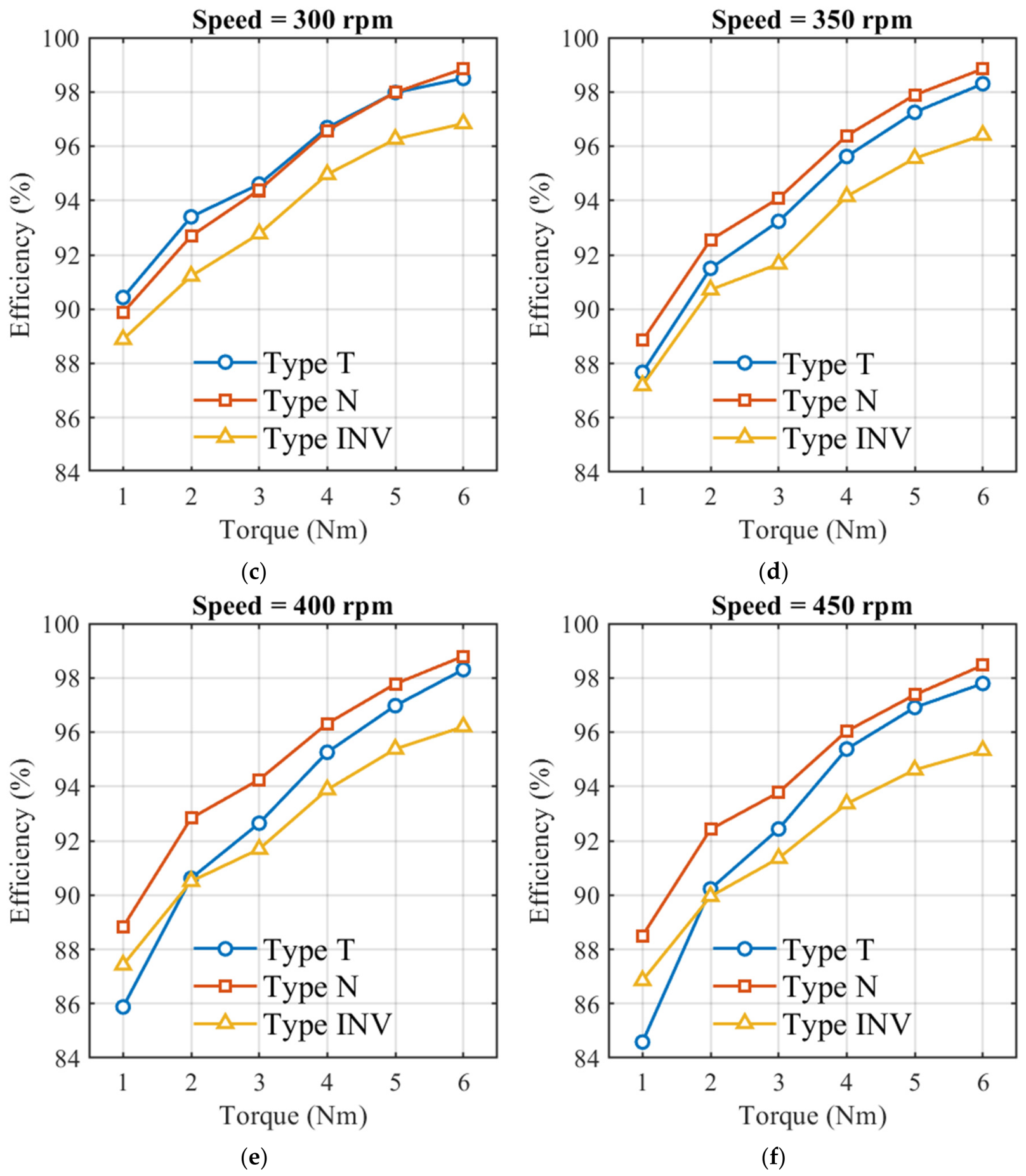
As shown in Figure 7, the transmission efficiency of all three gear pairs exhibits a pronounced dependence on the operating conditions. At the same rotational speed, the transmission efficiency generally increases with increasing load torque. At the same load torque, the transmission efficiency shows an overall decreasing trend with increasing rotational speed. The transmission efficiency results for all 36 test conditions are presented in Table A1.
Figure 7.
Transmission efficiency of the investigated gear pairs under different loads and speeds: (a) 200 rpm; (b) 250 rpm; (c) 300 rpm; (d) 350 rpm; (e) 400 rpm; and (f) 450 rpm.
To facilitate a direct comparison of the power transmission performance of the different tooth profiles under a common operating condition, 400 rpm and 6 N·m were selected as the representative operating condition. This condition corresponds to the maximum load torque and is consistent with the 400 rpm and 6 N·m condition used in the thermal response tests. Under this condition, the transmission efficiencies of Type N, Type T, and Type INV were 98.795%, 98.305%, and 96.204%, respectively. The transmission efficiency of Type N was 0.49 and 2.59 percentage points higher than those of Type T and Type INV, respectively.
3.3. Acoustic Characteristics
The acoustic tests used the same test matrix as the transmission efficiency tests, with rotational speeds of 200, 250, 300, 350, 400, and 450 rpm and load torques of 1–6 N·m. Sound pressure levels were measured for the three gear pairs under the same test conditions, measurement position, and measurement distance.
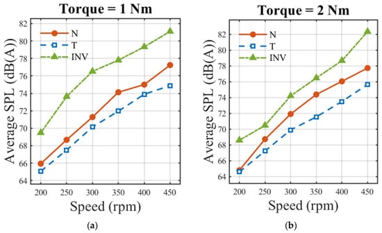
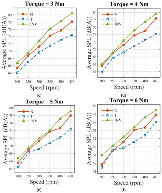
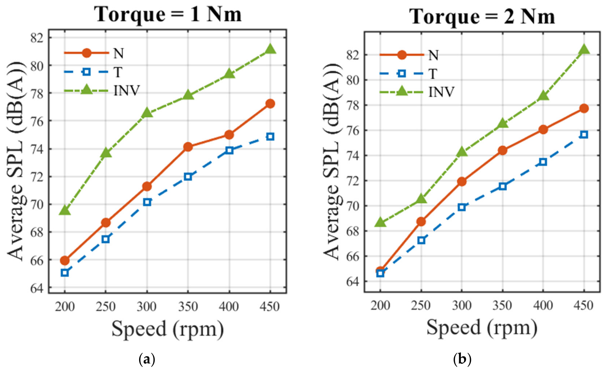
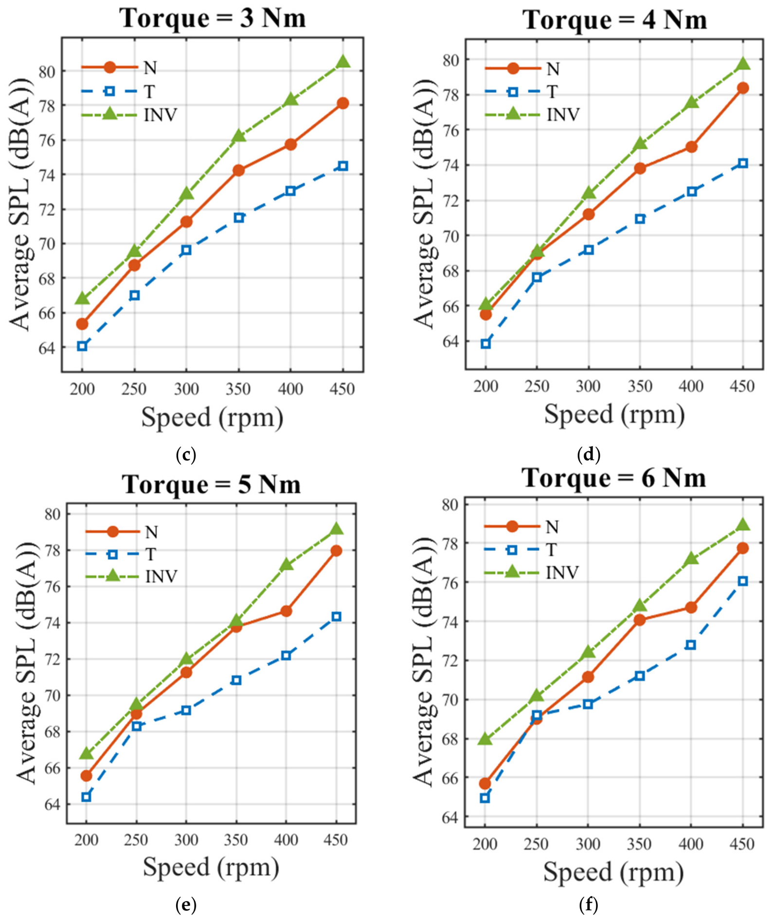
As shown in Figure 8, the sound pressure level of all three gear pairs generally increases with increasing input rotational speed, and the results for all 36 test conditions are presented in Table A2. Acoustic measurements were performed using a Wensn WS1361 sound level meter with A-weighting and the Slow time-response mode. After the gear pair reached a stable operating condition, the average sound pressure level over a continuous 30 s interval was recorded. Before the formal tests, the background sound pressure level was measured at 44.5 dB(A) under the same environmental conditions. The background sound pressure level was not directly subtracted from the measured levels in decibel units; instead, the sound pressure levels of the different gear pairs were compared under the same experimental environment and measurement conditions.
Figure 8.
Sound pressure level of the investigated gear pairs under different loads and speeds: (a) 1 N·m; (b) 2 N·m; (c) 3 N·m; (d) 4 N·m; (e) 5 N·m; and (f) 6 N·m.
For direct comparison under the same operating condition used for the transmission efficiency and thermal response tests, 400 rpm and 6 N·m were also selected as the representative operating condition. Under this condition, the sound pressure levels of Type T, Type N, and Type INV were 72.78, 74.71, and 77.16 dB(A), respectively. The sound pressure level of Type T was 1.93 dB(A) lower than that of Type N, while that of Type N was 2.45 dB(A) lower than that of Type INV.
3.4. Thermal Characteristics
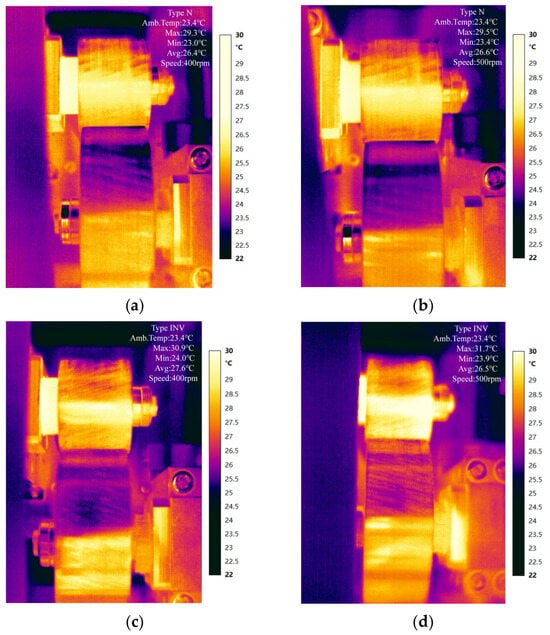
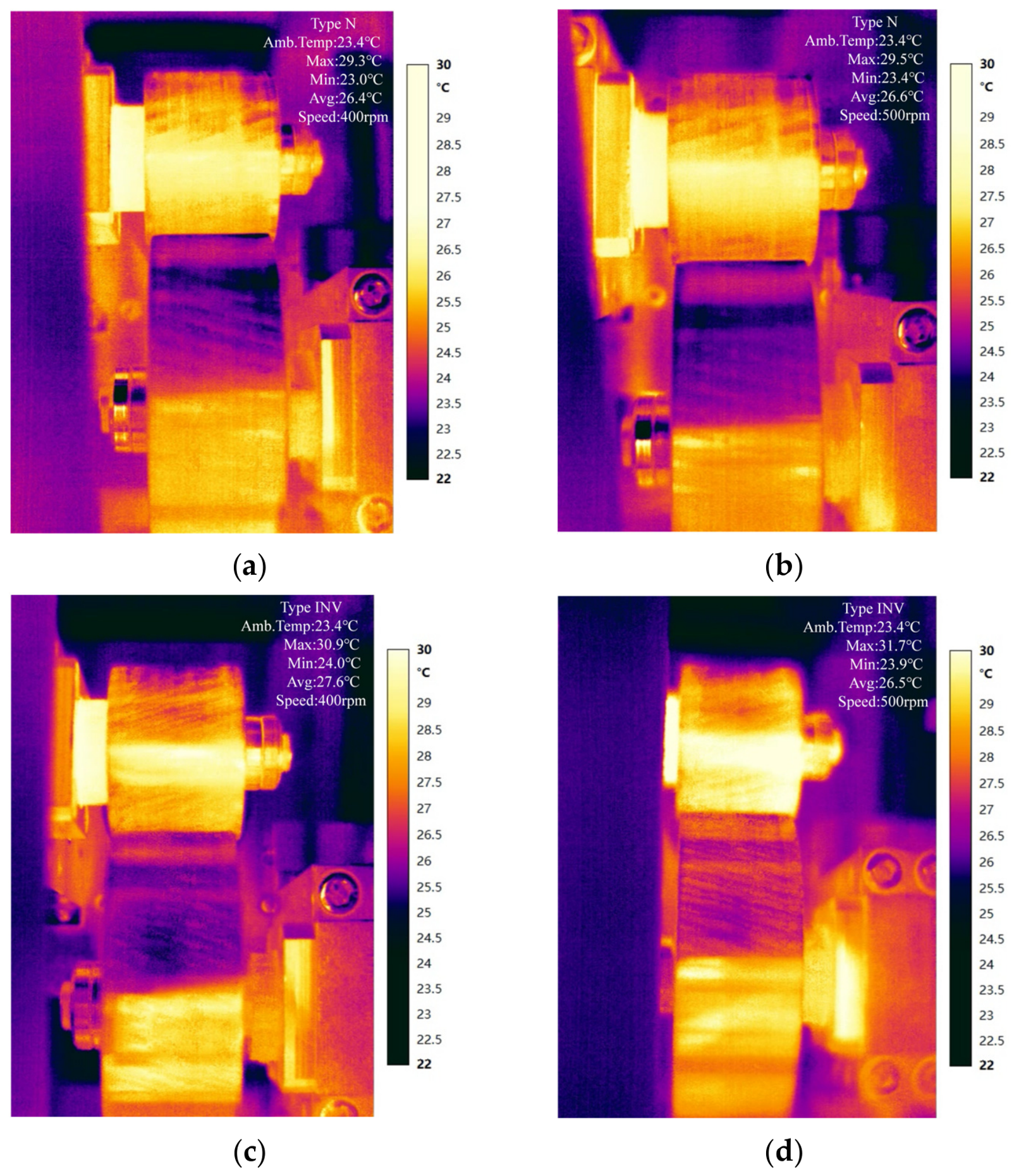
Thermal response tests were conducted for Type N and Type INV at rotational speeds of 400 and 500 rpm under a load torque of 6 N·m. Each gear pair was operated continuously for 1 h, and the area-averaged surface temperature within the predefined meshing region was obtained using a Fluke TiX580 infrared thermal imaging camera. The ambient temperature was 23.4 °C, and the same environmental conditions, temperature measurement region, and data extraction method were used for both gear pairs.
At 400 rpm, thermal response tests were conducted for Type N and Type INV under a load torque of 6 N·m. After 1 h of continuous operation, the area-averaged surface temperature within the predefined meshing region of Type INV was 27.6 °C, corresponding to a temperature rise of 4.2 °C. Under the same conditions, the corresponding temperature and temperature rise for Type N were 26.4 °C and 3.0 °C, respectively. Thus, the temperature-rise reduction ratio of Type N relative to Type INV was 28.6%.
At 500 rpm, the area-averaged surface temperatures of Type INV and Type N after 1 h of continuous operation were 27.5 °C and 26.6 °C, respectively, corresponding to temperature rises of 4.1 °C and 3.2 °C. The temperature-rise reduction ratio of Type N relative to Type INV was 22.0%. The detailed results are presented in Figure 9 and Table 6.
Figure 9.
Infrared thermal images of Type N and Type INV at 6 N·m after 1 h of operation: (a) Type N at 400 rpm; (b) Type N at 500 rpm; (c) Type INV at 400 rpm; (d) Type INV at 500 rpm.
Table 6.
Thermal response of Type N and Type INV at 6 N·m after 1 h of operation.
It should be noted that the thermal metrics used here represent the area-averaged surface temperature within the predefined meshing region and the corresponding temperature rise after 1 h of continuous operation. Therefore, the results characterize the differences in thermal response under the prescribed operating time and test conditions, rather than defining the temperature after 1 h as a strict thermal steady-state temperature.
4. Discussion
This study evaluates the transmission performance of different tooth-profile forms through the LTE comparison and experimental assessments of energy transmission, acoustic response, and thermal response. The results show that the different tooth profiles do not exhibit identical performance across these dimensions, indicating that tooth-profile design has multidimensional effects on gear transmission performance.
4.1. Effect of Tooth-Profile Definition on Loaded Motion Transmission
Under all investigated helix angle conditions from 10° to 45°, the peak-to-peak LTE of Type T is lower than that of Type N, while both types exhibit non-monotonic variations. This result indicates that the pure rolling contact condition alone does not uniquely determine the LTE among different pure rolling tooth-profile definitions, and that the tooth-profile definition and the resulting spatial active tooth surface also affect loaded motion transmission [24,25].
Type N and Type T adopt the same basic geometric parameters and circular-arc tooth-profile construction parameters, with the primary difference being that the circular-arc tooth profiles are defined in the normal section and transverse section, respectively. After spatial transformation, the two tooth profiles form different geometric relationships of the active tooth surfaces, which may further alter the contact region and load transmission state under loaded conditions, thereby resulting in different LTE responses. The non-monotonic variation of LTE with helix angle also indicates that LTE is not a simple function of helix angle alone but may be jointly influenced by the spatial contact geometry and loading conditions.
Therefore, optimization of the motion transmission performance of pure rolling gears should not focus solely on the pure rolling contact condition; the section in which the tooth profile is defined and the resulting three-dimensional active tooth surface should also be considered.
4.2. Transmission Efficiency and Energy Loss
Within the tested range of 200–450 rpm and 1–6 N·m, all three gear pairs exhibit a clear dependence of transmission efficiency on operating conditions. The efficiency generally increases with increasing load torque but decreases overall with increasing rotational speed. The results for all 36 test conditions are presented in Table A1. At the representative operating condition of 400 rpm and 6 N·m, the transmission efficiencies of Type N, Type T, and Type INV are 98.795%, 98.305%, and 96.204%, respectively.
At the selected comparison condition of 400 rpm and 6 N·m, both Type N and Type T exhibit higher measured transmission efficiencies than Type INV, consistent with the design objective of pure rolling gears. Type N also exhibits slightly higher measured efficiency than Type T under this condition, indicating that the tooth-profile definition and the resulting spatial active tooth surface are associated with differences in measured power-transmission performance.
As the load torque increases, the transmitted mechanical power increases, while the corrected power loss attributed to the gear pair does not increase proportionally, resulting in an overall increase in transmission efficiency. As rotational speed increases, the corrected power loss may increase relative to the transmitted power, contributing to the observed overall decrease in efficiency. These trends reflect the combined effects of operating conditions and the transmission characteristics of the tested gear pairs.
4.3. Acoustic Response and Its Association with LTE
The sound pressure level of all three gear pairs generally increases with increasing input rotational speed, indicating that operating speed is an important factor affecting the acoustic response within the tested range. At the representative operating condition of 400 rpm and 6 N·m, the sound pressure levels of Type T, Type N, and Type INV are 72.78, 74.71, and 77.16 dB(A), respectively. Type T is lower by 1.93 dB(A) than Type N, while Type N is 2.45 dB(A) lower than Type INV.
Across the tested operating conditions, Type T generally exhibits a lower sound pressure level. This trend is consistent with the lower LTE reported for Type T across the investigated helix angle range. LTE characterizes fluctuations in loaded motion transmission; its periodic variation can contribute to dynamic excitation of the gear and shaft system and thereby influence acoustic response [26]. The lower LTE and lower sound pressure level observed for Type T are therefore consistent with the possibility that improved loaded motion transmission contributes to its acoustic performance.
The measured sound pressure level is also influenced by manufacturing deviations, tooth-surface geometry, contact stiffness, shaft-system dynamics, installation conditions, and structural response of the experimental system [27]. Accordingly, LTE-related excitation is one factor to consider when interpreting the acoustic results, together with these other influences on the measured sound pressure level.
In addition, although Type N exhibits higher transmission efficiency than Type T at the representative operating condition, its sound pressure level is simultaneously higher than that of Type T, indicating that energy transmission performance and acoustic response do not vary synchronously in a simple manner. Therefore, the performance evaluation of pure rolling gears should consider both mechanical power transmission and dynamic response rather than relying on a single performance metric.
4.4. Thermal Response and Heat-Generation Considerations
Under a load torque of 6 N·m and after 1 h of continuous operation, the temperature rises in the meshing region of Type N were 3.0 °C and 3.2 °C at 400 and 500 rpm, respectively, whereas those of Type INV were 4.2 °C and 4.1 °C, respectively. The corresponding temperature-rise reduction ratios were 28.6% and 22.0%.
The thermal comparison was designed to examine the difference between the representative pure rolling configuration and the conventional involute reference in terms of thermal response. At the selected comparison condition of 400 rpm and 6 N·m, the transmission efficiencies of Type N and Type T differed by only 0.49 percentage points, whereas the corresponding power-loss fraction estimated from the measured transmission efficiency was approximately 3.15 times higher for Type INV than for Type N. This contrast indicates that the principal efficiency-related distinction in the investigated gear sets lies between the pure rolling and involute configurations, while the efficiency difference between the two pure rolling configurations is comparatively small under the selected condition. Accordingly, Type N was used as the representative pure rolling configuration for the thermal comparison.
Type N exhibits a lower meshing-region surface-temperature rise at both test speeds, consistent with its higher measured transmission efficiency relative to Type INV. In gear transmissions, power losses, particularly those associated with tooth friction, contribute to heat generation and influence the thermal response [28]. The measured temperature response also depends on heat conduction and dissipation within the gear pair and experimental system.
The temperature-rise reduction ratio decreased from 28.6% at 400 rpm to 22.0% at 500 rpm, indicating that the thermal response may also be affected by rotational speed, heat conduction, and heat-dissipation conditions of the experimental system. The thermal results therefore characterize the comparative response of the representative pure rolling Type N and conventional Type INV under the prescribed operating conditions.
4.5. Engineering Implications and Study Scope
Taken together, the results indicate that Type N and Type T exhibit different performance characteristics across the investigated dimensions. Type N shows higher transmission efficiency under the selected comparison condition and a lower meshing-region surface temperature rise than Type INV, whereas Type T exhibits lower LTE and sound pressure level. These results indicate that the choice of tooth-profile configuration involves trade-offs among energy transmission, motion transmission, acoustic response, and thermal response, and should therefore be considered in relation to the specific application requirements.
All three gear types were fabricated from 40Cr steel using the same target manufacturing-accuracy grade and comparable manufacturing conditions. Manufacturing deviations and heat-treatment deformation may influence tooth contact, motion transmission, efficiency, and acoustic response. Because one physical gear pair was tested for each tooth-profile form, the present results characterize the tested specimens under the specified conditions. Future work will include independent metrology of the finished gears, including profile, pitch, helix, radial-runout, and surface-roughness measurements, as well as hardness testing after heat treatment. Repeated measurements and additional independently manufactured gear pairs accompanied by detailed gear-accuracy inspection reports will be used to assess measurement repeatability and specimen-to-specimen variation.
All experiments in the present study were conducted under dry-running conditions. Routine visual observations after testing showed no obvious wear, scuffing, or surface discoloration, although wear was not quantified. Future work will include calibration of the measurement instruments and uncertainty-propagation analysis for torque, speed, transmission efficiency, sound pressure level, and temperature measurements. To directly validate LTE experimentally, a synchronized angular-position measurement system for both shafts will be developed, and LTCA mesh-convergence and contact-parameter sensitivity studies will be conducted under loading conditions corresponding to the experiments. Experimental testing at the 150 N·m numerical load will be considered when a suitable high-torque test rig is available. Further investigations will also examine alternative gear materials and verified heat-treatment conditions, controlled lubricated operation, longer-duration running, post-test surface damage, and quantitative characterization of local sliding, frictional power loss, and heat dissipation.
5. Conclusions
Based on the previously established design method for pure rolling gears with circular-arc tooth profile in the normal section, Type N, Type T, and Type INV gear pairs were fabricated and comparatively investigated using LTCA and experiments under unified test conditions. The main conclusions are as follows:
- (1)
- The LTCA results show that the peak-to-peak LTE of both Type N and Type T varies non-monotonically over the investigated helix angle range of 10–45°. Type T exhibits lower peak-to-peak LTE than Type N at all investigated helix angles, indicating that the section used to define the circular-arc tooth profile is associated with differences in loaded motion transmission.
- (2)
- Within the experimental ranges of 200–450 rpm and 1–6 N·m, the transmission efficiency of all three gear pairs generally increases with load torque and decreases with rotational speed. At the selected comparison condition of 400 rpm and 6 N·m, the measured transmission efficiencies of Type N, Type T, and Type INV were 98.795%, 98.305%, and 96.204%, respectively. Type N and Type T exhibited similar measured transmission efficiencies, while both pure rolling gear pairs showed higher measured efficiencies than Type INV under this operating condition.
- (3)
- The sound pressure level of all three gear pairs generally increases with rotational speed. At 400 rpm and 6 N·m, the measured sound pressure levels of Type T, Type N, and Type INV were 72.78, 74.71, and 77.16 dB(A), respectively. Type T recorded the lowest sound pressure level among the three tested gear pairs. This trend is consistent with its lower peak-to-peak LTE, suggesting a possible association between loaded motion-transmission characteristics and acoustic response.
- (4)
- After 1 h of continuous operation at 6 N·m, the meshing-region temperature rises of Type N were 3.0 °C and 3.2 °C at 400 and 500 rpm, respectively, compared with 4.2 °C and 4.1 °C for Type INV. The corresponding temperature-rise reduction ratios were 28.6% and 22.0%, respectively. Under the tested conditions, Type N exhibited a lower meshing-region surface temperature rise than Type INV.
- (5)
- The investigated tooth-profile configurations exhibit different performance characteristics in energy transmission, motion transmission, acoustic response, and thermal response. Their overall performance should therefore be evaluated using multiple indicators rather than a single metric.
Author Contributions
Conceptualization, C.Z. and H.Y.; methodology, C.Z., X.X. (Xikai Xiang). and H.Y.; software, C.Z.; validation, C.Z., X.X. (Xikai Xiang)., Z.F. and Z.Z.; formal analysis, C.Z.; investigation, C.Z. and X.X. (Xiaoping Xiao).; resources, Z.C.; data curation, C.Z., Z.F.; writing—original draft preparation, C.Z.; writing—review and editing, C.Z.; visualization, C.Z.; supervision, Z.C.; project administration, Z.C.; funding acquisition, Z.C. All authors have read and agreed to the published version of the manuscript.
Funding
This research was funded by the National Natural Science Foundation of China (No. 52275073 and 52405056), the State Key Laboratory of Mechanical Transmission for Advanced Equipment, Chongqing University (No. SKLMT-MSKFKT-202416), the Zhanjiang Municipal Science and Technology Project (No. 2025B01058) and the Program for Scientific Research Start-up Funds of Guangdong Ocean University (Nos. YJR23002, YJR22016, YJR23010 and YJR24019), the Guangdong Ocean University Student Innovation Team Project—MechLink Team (No. CXTD2026005).
Data Availability Statement
The original contributions presented in this study are included in the article. Further inquiries can be directed to the corresponding authors.
Conflicts of Interest
The authors declare no conflicts of interest.
Abbreviations
The following abbreviations are used in this manuscript:
| LTE | Loaded Transmission Error |
| LTCA | Loaded Tooth Contact Analysis |
| SPL | Sound Pressure Level |
Appendix A
The following tables provide the detailed experimental data supporting the graphical results presented in Figure 7 and Figure 8. Table A1 reports the transmission efficiencies of Type N, Type T, and Type INV under 36 speed–torque combinations, covering rotational speeds of 200–450 rpm and load torques of 1–6 N·m. Table A2 presents the corresponding sound pressure levels measured under the same operating conditions. These tables preserve the complete numerical results and facilitate detailed examination and comparison of the transmission and acoustic performance of the three gear pairs.
Table A1.
Transmission efficiency of the investigated gear pairs under different operating conditions.
Table A2.
Sound pressure level of the investigated gear pairs under different operating conditions.
References
- Sun, M.; Lu, C.; Liu, Z.; Sun, Y.; Chen, H.; Shen, C. Classifying, Predicting, and Reducing Strategies of the Mesh Excitations of Gear Whine Noise: A Survey. Shock Vib. 2020, 2020, 9834939. [Google Scholar] [CrossRef] [Scilit]
- Pleguezuelos, M.; Pedrero, J.I.; Sánchez, M.B. Analytical Expressions of the Efficiency of Standard and High Contact Ratio Involute Spur Gears. Math. Probl. Eng. 2013, 2013, 142849. [Google Scholar] [CrossRef] [Scilit]
- Li, W.; Chen, G.; Li, Z.; Zhang, J.; Liu, M. Acoustic-Vibration Simulation Analysis of Multistage Gear-Shaft-Housing Coupled System. J. Braz. Soc. Mech. Sci. Eng. 2025, 47, 225. [Google Scholar] [CrossRef] [Scilit]
- Cianciotta, L.; Cirelli, M.; Valentini, P.P. Multi-Objective Optimization of Gear Design of E-Axles to Improve Noise Emission and Load Distribution. Machines 2025, 13, 330. [Google Scholar] [CrossRef] [Scilit]
- Radzevich, S.P. (Ed.) Gear Accuracy: A Treatise on Gear Noise Excitation, Vibration Generation, and Dynamics of Operation; Springer: Cham, Switzerland, 2024. [Google Scholar] [CrossRef] [Scilit]
- Paschold, C.; Lohner, T.; Stahl, K. Local Calculation of Load-Dependent Gear Power Losses of Cylindrical Gears. J. Tribol. 2025, 147, 112201. [Google Scholar] [CrossRef] [Scilit]
- Yue, K.; Kang, Z.; Zhang, M.; Wang, L.; Shao, Y.; Chen, Z. Study on Gear Meshing Power Loss Calculation Considering the Coupling Effect of Friction and Dynamic Characteristics. Tribol. Int. 2023, 183, 108378. [Google Scholar] [CrossRef] [Scilit]
- Horváth, K.; Feszty, D. The Impact of Pitch Error on the Dynamics and Transmission Error of Gear Drives. Appl. Sci. 2025, 15, 7851. [Google Scholar] [CrossRef] [Scilit]
- Wagner, M.J.; Ng, W.F.; Dhande, S.G. Profile Synthesis and Kinematic Analysis of Pure Rolling Contact Gears. J. Mech. Des. 1992, 114, 326–333. [Google Scholar] [CrossRef] [Scilit]
- Lohner, T.; Paschold, C. A Pathway towards Energy Efficiency Classes for Gearboxes Related to Superefficiency. Forsch. Ingenieurwes. 2025, 89, 2. [Google Scholar] [CrossRef] [Scilit]
- Chen, Z.; Zeng, M.; Fuentes-Aznar, A. Geometric Design, Meshing Simulation, and Stress Analysis of Pure Rolling Cylindrical Helical Gear Drives. Proc. Inst. Mech. Eng. Part C J. Mech. Eng. Sci. 2020, 234, 3102–3115. [Google Scholar] [CrossRef] [Scilit]
- Chen, Z.; Lei, B.; Zeng, M.; Li, Y.; Fuentes-Aznar, A. Computerized Design, Simulation of Meshing and Stress Analysis of Pure Rolling Internal Helical Gear Drives with Combined Tooth Profiles. Mech. Mach. Theory 2022, 176, 104959. [Google Scholar] [CrossRef] [Scilit]
- Chen, Z.; Zeng, M. Design of Pure Rolling Line Gear Mechanisms for Arbitrary Intersecting Shafts. Proc. Inst. Mech. Eng. Part C J. Mech. Eng. Sci. 2019, 233, 5515–5531. [Google Scholar] [CrossRef] [Scilit]
- Chen, Z.; Zhang, H.; Xiao, X.; He, C.; Zhu, K.; Chen, Y.; Fuentes-Aznar, A. Computerized Design of Asymmetric Pure Rolling Gears with a Method for Predesigning the Desired Function of Unloaded Transmission Errors. Mech. Mach. Theory 2025, 213, 106072. [Google Scholar] [CrossRef] [Scilit]
- Chen, Y.; Chen, Z.; Xiao, X.; He, C. Theory and Application Foundation of Line Gears; Science Press: Beijing, China, 2025. [Google Scholar]
- Xiao, X.; Chen, Y.; Xie, X.; Shao, Y. A Miniature Non-Circular Line Gear with Pure Rolling Contact. J. Adv. Mech. Des. Syst. Manuf. 2021, 15, JAMDSM0071. [Google Scholar] [CrossRef] [Scilit]
- Rong, K.; Tang, J.; Tian, Z.; Song, B.; Li, H.; Ding, H. A Novel Accurate-Efficient Loaded Contact Analysis Method for Hypoid Gears Based on Ease-Off Topography Discretization and TE-Interference Assessment. Mech. Mach. Theory 2025, 209, 106012. [Google Scholar] [CrossRef] [Scilit]
- Chen, Z.; Yang, H.; Xiao, X.; He, C.; Zhu, K.; Chen, Y.; Fuentes-Aznar, A. Computerized Design, Tooth Contact Analysis and Stress Analysis of Pure Rolling Gear Drive with Circular Arc Tooth Profile in the Normal Section. Adv. Mech. Eng. 2025, 17, 16878132251327072. [Google Scholar] [CrossRef] [Scilit]
- Constien, L.; Weber, M.; Pellkofer, J.; Stahl, K. Efficiency of Bevel and Hypoid Gears—Test Rig Development and Experimental Investigations. Machines 2024, 12, 647. [Google Scholar] [CrossRef] [Scilit]
- Xia, N.; Zhou, C.; Hou, S.; Zhang, F. A Data-Driven Friction Coefficient Model and Its Application in Meshing Efficiency Prediction of Heavy-Duty Gears. Simul. Model. Pract. Theory 2025, 144, 103173. [Google Scholar] [CrossRef] [Scilit]
- Mughal, H.; Dolatabadi, N.; Crew, J.; King, P.; Gnanakumarr, M.; Varnier, O. Comprehensive Tribodynamic Analysis of Lubricated Gear Contacts for Direct Identification of Gear Whine Noise in Electric Drive Units. Mech. Syst. Signal Process. 2025, 236, 113054. [Google Scholar] [CrossRef] [Scilit]
- Dai, L.; Liu, Y.; Jia, Y.; Zhou, W.; Zhang, A. Research on Gear Whine Evaluation Method Based on Transmission Error Sensitivity. J. Phys. Conf. Ser. 2024, 2827, 012024. [Google Scholar] [CrossRef] [Scilit]
- Černe, B.; Petkovšek, M.; Duhovnik, J.; Tavčar, J. Thermo-Mechanical Modeling of Polymer Spur Gears with Experimental Validation Using High-Speed Infrared Thermography. Mech. Mach. Theory 2020, 146, 103734. [Google Scholar] [CrossRef] [Scilit]
- Chen, Y.-C.; Lo, C.-C. Contact Stress and Transmission Errors under Load of a Modified Curvilinear Gear Set Based on Finite Element Analysis. Proc. Inst. Mech. Eng. Part C J. Mech. Eng. Sci. 2015, 229, 191–204. [Google Scholar] [CrossRef] [Scilit]
- Im, D.; Chung, W.-J.; Lee, H.; Lee, Y.-J.; Sung, H.; Lee, M.; Park, Y.-J. Analysis of Gear Transmission Error in Helical Gear Using Enhanced Tooth Contact Analysis Model Considering Measured Tooth Profile Errors. Sci. Rep. 2025, 15, 5981. [Google Scholar] [CrossRef] [Scilit] [PubMed]
- Marek, T.; Nemecek, P. Transmission Error and Sound Pressure Level of Spur Gearing with Straight and Helical Teeth. MM Sci. J. 2022, 2022, 6069–6073. [Google Scholar] [CrossRef] [Scilit]
- Guo, F.; Fang, Z. Experimental and Theoretical Study of Gear Dynamical Transmission Characteristic Considering Measured Manufacturing Errors. Shock Vib. 2018, 2018, 9645453. [Google Scholar] [CrossRef] [Scilit]
- Koffel, G.; Ville, F.; Changenet, C.; Velex, P. Investigations on the Power Losses and Thermal Effects in Gear Transmissions. Proc. Inst. Mech. Eng. Part J J. Eng. Tribol. 2009, 223, 469–479. [Google Scholar] [CrossRef] [Scilit]

Disclaimer/Publisher’s Note: The statements, opinions and data contained in all publications are solely those of the individual author(s) and contributor(s) and not of MDPI and/or the editor(s). MDPI and/or the editor(s) disclaim responsibility for any injury to people or property resulting from any ideas, methods, instructions or products referred to in the content. |
© 2026 by the authors. Licensee MDPI, Basel, Switzerland. This article is an open access article distributed under the terms and conditions of the Creative Commons Attribution (CC BY) license.