


Abstract
Complex multi-rotor aeroengine systems exhibit intricate dynamic behaviours governed by mass distribution, rotor stiffness, bearing flexibility, and assembly coaxiality errors. Establishing accurate and physically representative dynamic models is essential to interpret their vibration characteristics. Taking a turbofan aeroengine dual-rotor configuration as the research object, this paper constructs a rigid–flexible coupled dynamic model within a multi-body dynamics framework. In this model, the fan and high-pressure rotors are simplified as rigid bodies, while squirrel-cage elastic supports and the slender low-pressure turbine shaft are defined as flexible components to improve modelling fidelity. Modal validation against prototype measured data shows that the developed rigid–flexible coupled model yields a maximum natural-frequency relative error of 11.31%, while the fully-rigid model suffers from severe prediction deviation with the maximum relative error reaching 102.37%. Three typical rotor faults, namely multi-disc random multi-phase unbalance, support misalignment, and stator–rotor rub-impact behaviour, are numerically simulated to extract fault-related vibration signatures. Further experimental investigations are carried out on a dual-rotor test rig: critical-speed identification, unbalance-driven vibration, support-misalignment, and fixed-point rub-impact tests. Measured vibration responses under different fault conditions qualitatively corroborate the key simulation predictions, which further validates the reliability and practicability of the rigid–flexible coupled modelling strategy. This work provides a high-precision modelling framework for dual-rotor assemblies and supplies experimental-supported fault-vibration datasets, offering technical references for vibration monitoring and intelligent fault diagnosis of aeroengine rotor systems.
1. Introduction
Originating in the 1860s, rotor dynamics constitutes a crucial branch of mechanical dynamics. Large rotating power machinery such as aeroengines, steam turbine generators, gas turbines, and centrifugal compressors universally suffers from severe and intricate vibration issues [1,2,3,4,5,6,7,8,9,10,11,12,13,14,15]. To reveal the motion laws of rotor assemblies and clarify their dynamic behaviours, it is indispensable to develop a dynamic model capable of reflecting core structural characteristics, which also serves as the fundamental premise for investigating rotor vibration theories of rotating equipment.
Aeroengine dual-rotor systems are equipped with multiple elastic supports and sophisticated structural configurations, whose dynamic responses are governed by numerous interacting factors. Reasonable model simplification is the key to balancing computational efficiency and prediction accuracy for rotor dynamic modelling. Domestic and overseas scholars have extensively studied dynamic modelling approaches for aeroengine dual-rotor systems and generated abundant representative research outcomes in recent years [16,17,18,19,20,21,22,23,24,25,26,27,28]. Existing multi-support dual-rotor models are generally grouped by lumped disk arrangements, including single-disk, two-disk, and multi-disk dual-rotor configurations. However, most available models follow either a fully flexible assumption or a pure lumped-mass simplification. When high-stiffness wheel discs are unnecessarily treated as flexible bodies, spurious elastic strain energy is introduced into dynamic calculations, which induces considerable deviations in vibration prediction. In contrast, conventional lumped-parameter models simplify discs as mass points and cannot independently assign unbalance vectors to individual discs; meanwhile, they often oversimplify the structure of discs and elastic supports, which weakens their capacity to simulate support misalignment and rotor–stator rubbing faults of specific discs. Furthermore, many reported models lack adequate experimental validation of their practicability and rationality for fault vibration analysis. In addition, Bukvić et al.’s research from 2025 [29] provides a reference method for understanding and suppressing the vibration of complex mechanical systems from the perspective of frictional control at the contact interface.
Against this background, this paper selects a dual-rotor layout equipped with multiple squirrel-cage elastic supports and a flexible low-pressure turbine shaft, where the inner and outer rotors generate coupling effects. A rigid–flexible coupling numerical model is constructed on the ADAMS multi-body dynamics platform: squirrel-cage supports and the low-pressure turbine shaft are set as flexible components, whereas the fan and high-pressure rotors adopt rigid-body simplification. This differentiated rigid–flexible treatment avoids redundant flexible degrees of freedom of stiff discs while retaining the deformation characteristics of key flexible components. Importantly, each disc can be assigned an independent unbalance vector, which enables Monte Carlo sampling of multi-disc, multi-phase random unbalance excitations. Benefiting from the retained flexibility of squirrel-cage supports and clear geometric definition of rigid discs, the model also supports the simulation of support misalignment and rotor–stator rub-impact faults. Subsequently, the model is utilized to reproduce various rotor abnormal vibration phenomena, including multi-disc multi-phase random unbalance, support misalignment, and stator–rotor rubbing. The vibration response under three types of faults was studied on the test bench. The simulation and experimental results verify that the established model can accurately reflect vibration features under typical rotor faults. The rigid–flexible coupled modelling strategy proposed in this paper can be generalized to all types of rotating machinery rotor assemblies.
2. Rigid–Flexible Coupled Dynamic Model of Dual-Rotor Assembly
2.1. Modelling Process
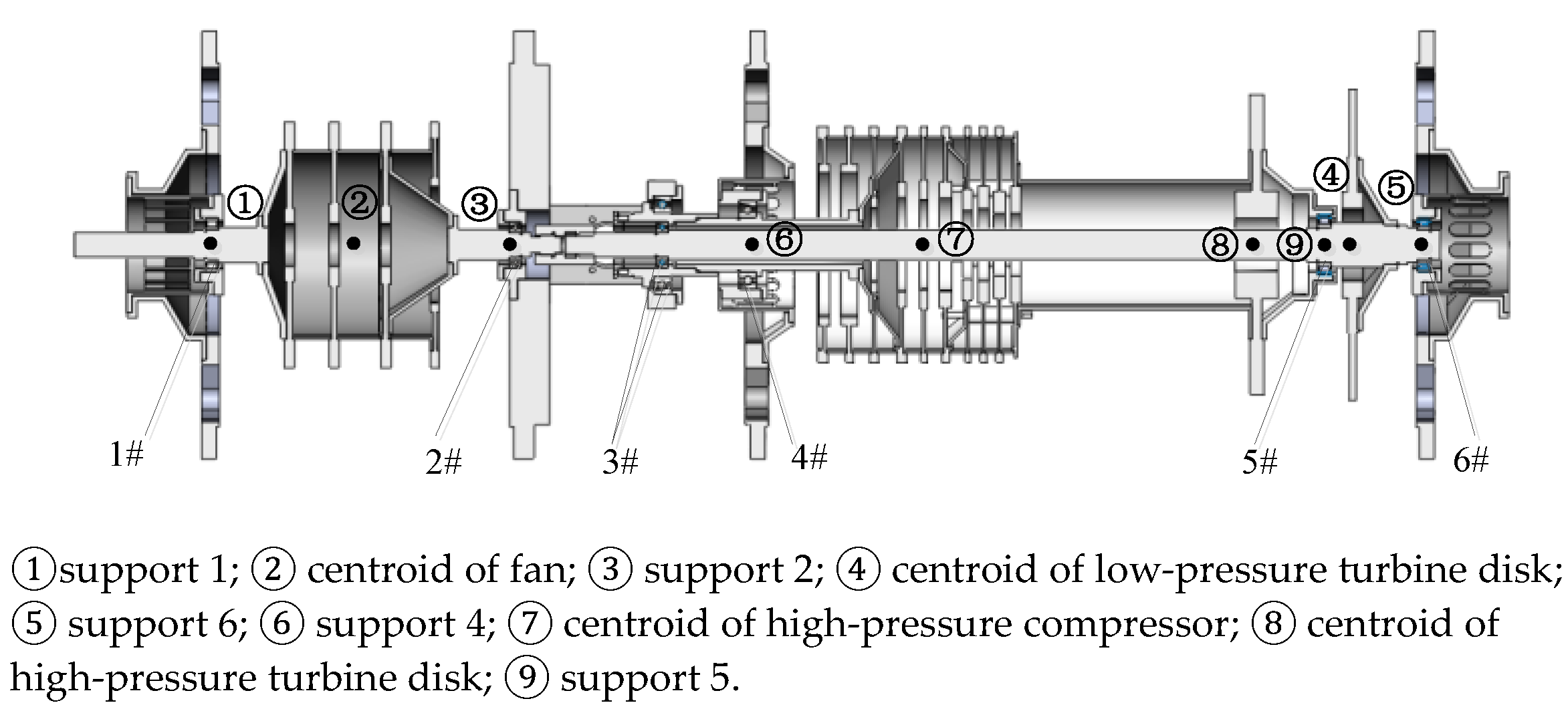
The low-pressure rotor comprised four fan stages and one turbine stage, with an overall length of approximately 2147.98 mm. The high-pressure rotor was 1134.99 mm long and consisted of a nine-stage compressor, a first-stage sealing disk, and a first-stage high-pressure turbine; the high-pressure compressor and high-pressure turbine were rigidly connected directly through a hollow shaft. This dual-rotor system, which is shown in Figure 1, possessed distinctive structural features: the slender thin-walled low-pressure turbine shaft penetrated the high-pressure rotor assembly, intershaft bearings coupled the high- and low-pressure rotors to produce structural interaction, and the system was fitted with multiple composite elastic supports combining squirrel-cage springs, rolling bearings, and squeeze-film dampers. Both the inner and outer rotors were constructed from multi-stage compressor disks and turbine wheels. Of the six bearing locations, supports 1, 4, and 6 were configured with squirrel-cage flexible structures, and measuring points ①–⑨ were deployed to capture vibration signals over the entire rotor system. The main parameters are shown in Appendix A.
Figure 1.
Schematic diagram of the dual-rotor system structure.
The ADAMS simulation platform is developed based on multi-body dynamic theories and integrates multiple professional mechanical analysis modules. The solver applies the gear rigid integration algorithm and sparse matrix-solving technology to remarkably promote computational efficiency. It can construct kinematic and dynamic models for complex mechanical equipment and integrate geometric constraints, mechanical loads, and boundary conditions of rotor assemblies into a unified simulation framework. The application of multi-body dynamics in rotor modelling provides innovative solutions for rigid–flexible coupling modelling and model verification of aeroengine rotors.
In this paper, flexible bodies were generated using the Craig–Bampton (CB) modal reduction method, which is the widely adopted component mode synthesis (CMS) approach native to the ADAMS/Flex module. First, the finite element model of the flexible component was established in ANSYS 18. A set of interface boundary nodes (connections to bearings, couplings, and adjacent components) was predefined as master boundary degrees of freedom (DOFs), and the remaining internal DOFs were treated as slave DOFs. A modal truncation threshold was prescribed to preserve only low-frequency fixed-interface modes within the frequency range of interest for rotor dynamic analysis, balancing model accuracy and computational expense. We then exported a reduced Modal Neutral File (MNF) containing boundary stiffness matrices, mass matrices, and modal information from ANSYS and imported it into ADAMS. ADAMS reconstructed the flexible body directly from this MNF file for the following multi-body dynamic simulation. Compared with alternative modal reduction schemes, the Craig–Bampton method preserves complete boundary DOF information, making it well-suited for assembling multi-body systems with force and motion transmission across component interfaces.
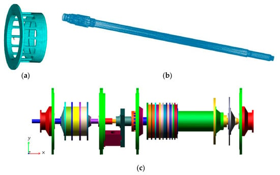
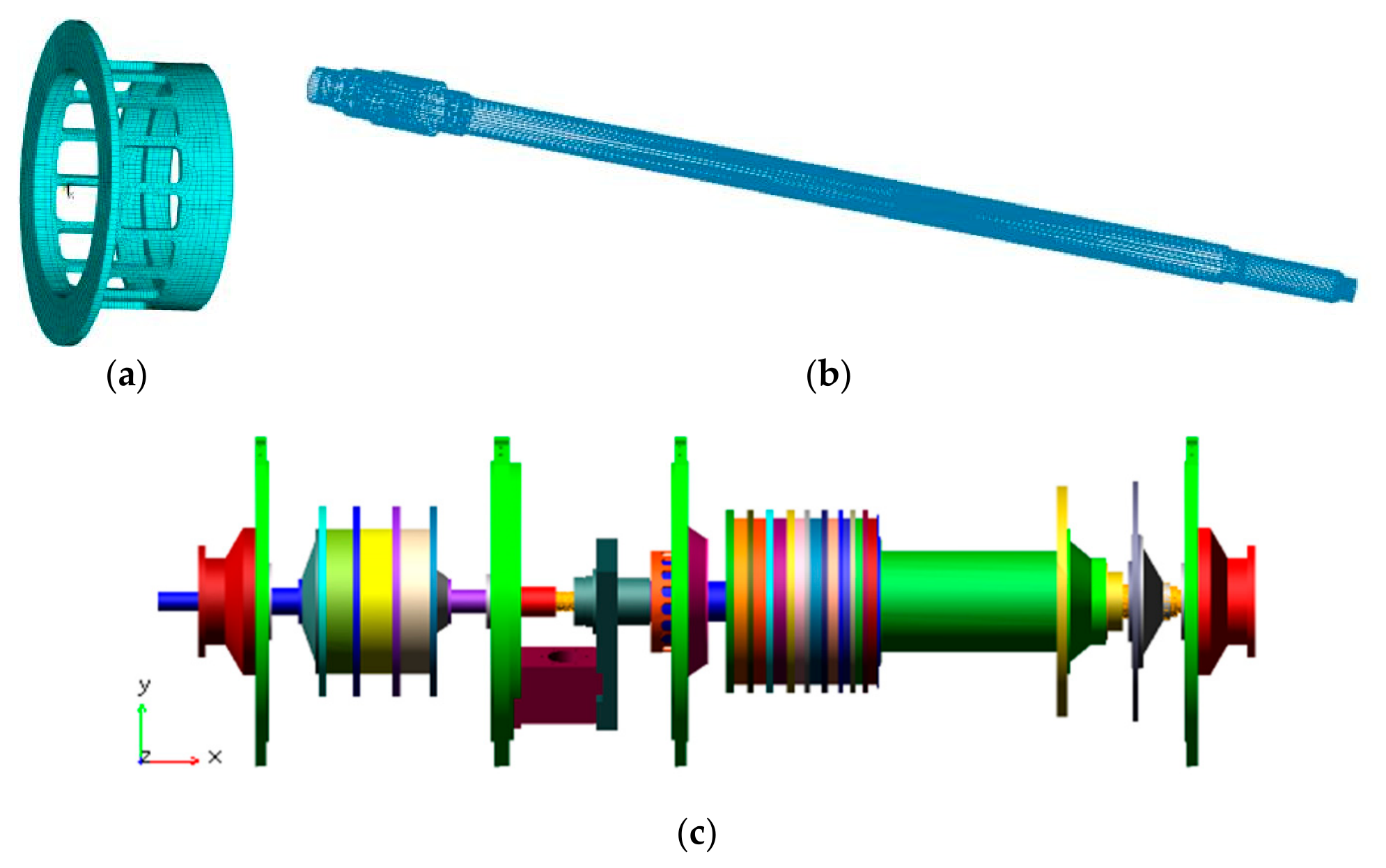
The multi-body dynamic numerical model built on ADAMS is illustrated in Figure 2. A global coordinate system o-XYZ was defined to describe spatial positions of all components, with the positive Y-axis specified as the zero initial phase angle. Due to its slender geometric feature, the low-pressure turbine shaft was assigned flexible body attributes; No. 1, No. 4, and No. 6 squirrel-cage supports are also defined as flexible parts, while all other structural components adopt the rigid-body hypothesis. The connection relationships inside the rotor system were processed as follows:
Figure 2.
Rigid–flexible coupling dynamic simulation model of flexible support-dual rotor system. (a) Grid model of squirrel cage; (b) grid model of low-pressure turbine shaft; (c) assembly multi-body dynamic model of dual-rotor system.
- Bolted fixed joints in practical structures were replaced by fixed constraints in the simulation;
- Rolling bearings were characterized via stiffness and damping parameters and simulated by bushing force elements;
- Rotor coupling structures were simplified as short rigid shafts.
Driving motions were applied at the central axes of low-pressure and high-pressure rotors to realize the rotational operation of the whole assembly.
To eliminate calculation errors induced by inadequate mesh resolution of flexible components, three mesh schemes (coarse, medium, and fine) were designed separately for the squirrel-cage support and low-pressure turbine shaft. The first three natural frequencies under each mesh configuration were extracted for comparison, as summarised in Table 1. The maximum frequency deviation between the medium mesh and the fine mesh was less than 0.3%, satisfying the required computational precision. Balancing numerical accuracy and computational cost, the medium mesh scheme was adopted for both flexible components. The corresponding grid model shown in Figure 2 was used for all subsequent full-condition simulations.
Table 1.
Mesh convergence results for the flexible squirrel-cage support and low-pressure turbine shaft.
2.2. Analysis of Inherent Modal Characteristics
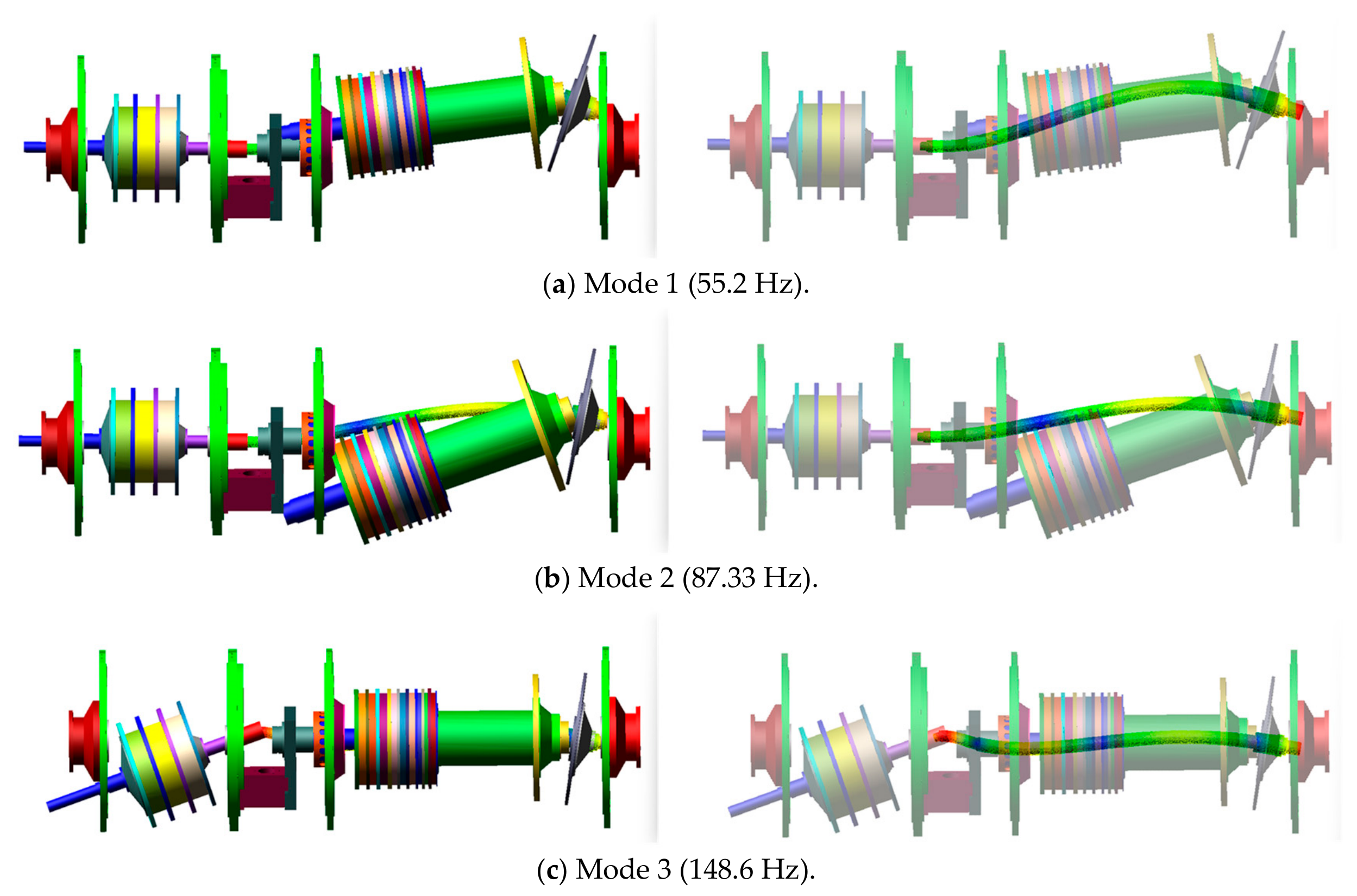
Natural frequency, an inherent property of rotary equipment, acts as a critical indicator for rotor fault diagnosis and vibration trend prediction. Modal analysis was carried out on the rigid–flexible coupled dual-rotor model, and representative modal shapes are summarized in Figure 3 as below:
- First-order mode: dominated by bending deformation of low-pressure turbine rotor and translational displacement of high-pressure rotor;
- Second-order mode: characterized by bending vibration of low-pressure turbine shaft and pitching swing of high-pressure rotor;
- Third-order mode: mainly manifested as pitching motion of low-pressure fan rotor and bending deformation of low-pressure turbine shaft.
Figure 3.
Modal characteristics of the rigid–flexible coupled dual-rotor assembly.
The abovementioned modal results were calculated at zero rotational speed without gyroscopic effects. For the rotating dual-rotor system, gyroscopic moments split the forward and backward whirling modes and alter frequency characteristics as rotational speed varies. Accordingly, the transient speed-sweep method was employed to identify the critical speeds of the dual-rotor assembly.
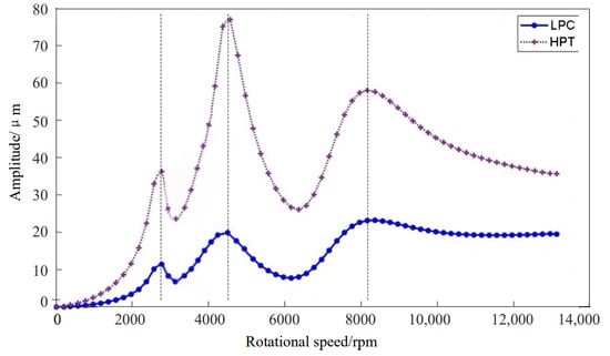
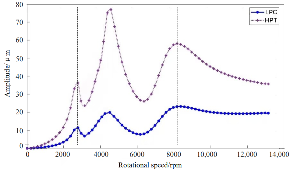
In this scheme, both the inner and outer rotors were accelerated from 0 to 13,000 r/min, and vibration response amplitudes at the measurement points were extracted at an equal speed interval of 200 r/min. Amplitude data at discrete rotational speeds were connected to construct vibration amplitude curves for the low-pressure fan disk (LPC) and high-pressure turbine disk (HPT), as shown in the Figure 4. Three distinct amplitude peaks can be observed throughout the speed-up process. The first peak appears at approximately 2800 r/min, the second at around 4600 r/min, and the third at about 8200 r/min. The rotational speeds corresponding to these peaks are regarded as the critical speeds of the dual-rotor system. This study also provides a basis for configuring vibration simulation operating conditions of rotor systems in follow-up investigations.
Figure 4.
Vibration amplitude curves of LPC and HPT during transient speed sweep (0–13,000 r/min).
2.3. Comparative Modal Analysis Between Full-Rigid Model and Rigid–Flexible Coupled Model
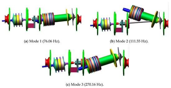
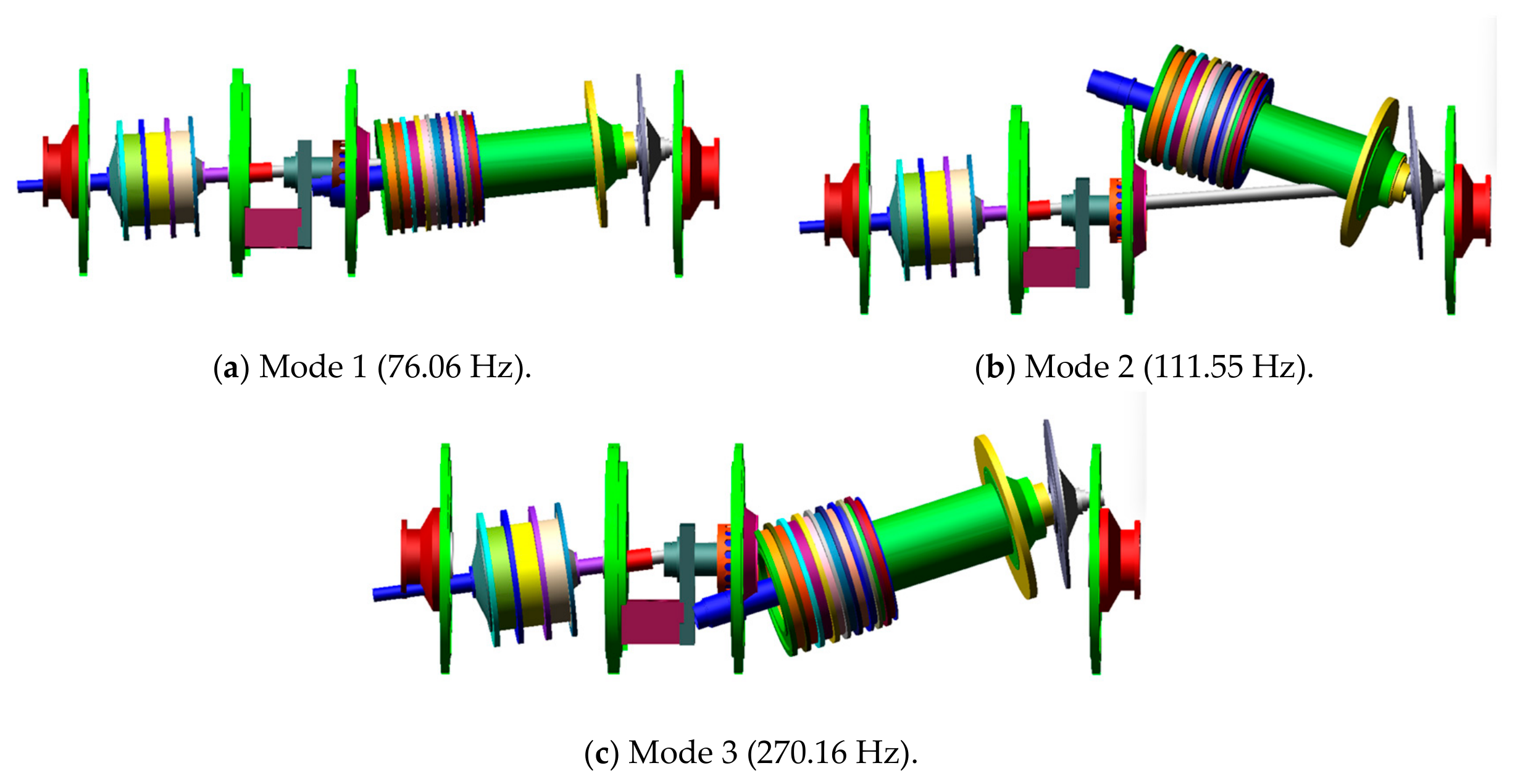
To highlight the superiority and necessity of the proposed rigid–flexible coupled modelling strategy, a full-rigid contrast model with identical geometric dimensions and bearing stiffness was established for comparison. The first three natural frequencies and corresponding mode shapes of the model are shown in Figure 5.
Figure 5.
Modal characteristics of the full-rigid dual-rotor assembly.
Table 2 quantitatively compares the first three natural frequencies of the test prototype, full-rigid numerical model, and the proposed rigid–flexible coupled model, and calculates the relative frequency deviation with the prototype measured data as the benchmark.
Table 2.
The first three natural frequencies of the prototype, full-rigid model, and rigid–flexible coupled model.
For the full-rigid model, neglecting the flexibility of key thin-walled shafts and multipoint elastic supports artificially raises the overall structural stiffness of the dual-rotor system, so all predicted natural frequencies are far higher than prototype test values. The first-order relative error reaches 36.55%, the second-order error approaches 40%, and the third-order error exceeds 100%. Such an enormous calculation deviation demonstrates that the full-rigid simplification cannot reflect the real stiffness distribution of an aeroengine dual-rotor assembly, and its modal prediction results lose practical engineering reference value.
In contrast, the rigid–flexible coupled model proposed in this paper distinguishes rigid and flexible components reasonably, and introduces the elastic deformation characteristics of the turbine shaft and squirrel-cage supports into the numerical solution. The first-order frequency error is only 0.90%, which realizes high-precision matching with the prototype test data. The second-order and third-order relative errors are controlled within 11.3%. The minor residual errors mainly come from the simplified processing of rolling bearing bushing parameters, mesh discretization of flexible bodies, and ignored tiny structural damping, which are within the acceptable error range of multi-body dynamics simulation.
From the overall comparison, the rigid–flexible partitioning modelling strategy proposed in this paper drastically reduces modal calculation errors compared with the traditional full-rigid scheme. The frequency prediction accuracy is greatly improved, which fully verifies the necessity and innovation of considering the flexible deformation of key supporting and shaft components in dual-rotor dynamic modelling.
Combining the quantitative frequency error comparison and qualitative mode shape contrast, three core conclusions can be drawn:
- The full-rigid scheme only simulates the global rigid-body motion of rotors and fails to reproduce elastic bending of key flexible components, which artificially amplifies system stiffness and leads to severely distorted modal frequencies.
- By distinguishing rigid and flexible components, the proposed model accurately reproduces the local bending deformation of key flexible parts, and its frequency values are highly consistent with prototype test data (maximum error less than 12%). The model can truly restore the coupling vibration characteristics of the aeroengine dual-rotor system.
- The comparative results fully verify that rigid–flexible partition modelling is a mandatory prerequisite for high-precision rotor dynamic analysis. Traditional full-rigid modelling produces unreliable modal results and is not suitable for subsequent fault vibration simulation and feature extraction of dual-rotor assemblies.
Overall, the rigid–flexible partitioning modelling method proposed in this paper greatly reduced modal calculation errors compared with conventional full-rigid modelling frameworks, which sufficiently validates the necessity and original contribution of incorporating flexible deformation of key supporting and shaft components in dual-rotor dynamic modelling.
3. Numerical Simulation of Typical Rotor Faults
Based on the established rigid–flexible coupled dual-rotor model, three frequent malfunctions, including random unbalance vector variation, bearing misalignment, and stator–rotor rub-impact behaviour, are simulated separately, and corresponding vibration response characteristics under each fault are analysed to validate the model’s fault reproduction capacity.
3.1. Simulation Methodology for Typical Rotor Malfunctions
Rotating machinery rotors suffer from diverse vibration failures, among which unbalancing, friction faults, and misalignment faults are the most common forms. The core of rotor dynamic research lies in developing numerical models capable of reproducing uneven mass distribution, bearing position deviation, rotor eccentricity, and collision friction, so as to quantitatively analyse vibration responses under abnormal operating conditions.
ADAMS provides two categories of dynamic solving algorithms for different simulation demands: (1) implicit integration solvers (GSTIFF, DSTIFF, BDF): three variable-order variable-step implicit algorithms to solve sparse nonlinear differential-algebraic equations, suitable for rigid systems with wide eigenvalue ranges. GSTIFF (short for “Generalized Stiff” integrator) is a DAE solver based on coordinate partitioning and BDF methods. Divide the generalized coordinates of the system into independent coordinates and non-independent coordinates. By constraining equations, non-independent coordinates can be uniquely determined by independent coordinates. In this way, the dynamics of the system are completely described by independent coordinate differential equations. DSTIFF is a “diagonalized implicit integrator” or “rigid damping integrator”, which is a DAE solver based on the methods of scaling and BDF. It does not partition the coordinates, but directly applies the BDF formula to the original complete index-3 DAE system -. It simultaneously substitutes the BDF formula into the motion differential equation and the position and velocity constraint equations, forming a huge nonlinear system of equations, and then directly solves all variables. BDF is an implicit, multi-step numerical integration method. It constructs a polynomial using the solutions of the past few time steps and the unknown solution of the current time step, and then approximates the derivative of the polynomial at the current time. It is the mathematical foundation of integrators such as GSTIFF and DSTIFF. (2) The ABAM (Adams–Bashforth–Adams–Moulton) integrated solver is a variable-step-size, variable-order algorithm used for explicit integration. Use the coordinate separation algorithm to solve differential equations of independent coordinates. This method is suitable for simulating systems with sudden changes in eigenvalues or high-frequency systems.
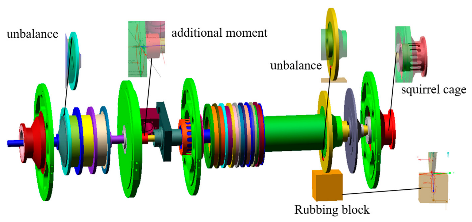
All fault simulation cases are implemented on the multi-body dynamics platform, with specific modelling methods for three faults listed as follows (Figure 6): (1) rotor unbalance: additional mass blocks are mounted on turbine/compressor discs, and unbalance vectors are controlled by adjusting mass block weight and circumferential installation angle; (2) rear support misalignment of low-pressure turbine rotor: the spatial position of squirrel-cage flexible support is offset to generate misalignment errors, and extra torque is exerted on rotor coupling to reflect misalignment-induced additional load; and (3) stator–rotor rub-impact behaviour: fixed mass blocks are added as stator structures, rubbing severity is adjusted by changing radial clearance and contact friction parameters, and collision positions are controlled by moving stator blocks. In all simulation cases, the rotating speeds of low-pressure rotor nLP and high-pressure rotor nHP are set to 3600 r/min and 4800 r/min, respectively.
Figure 6.
Simulation results of typical vibration faults in the dual-rotor system.
3.2. Vibration Response Analysis of Rotor System Under Random Multi-Disc Multi-Phase Unbalance
The researched dual-rotor assembly contains 13 compressor discs and 2 turbine discs, all of which may generate unbalance defects during operation. The low-pressure fan section includes four stages, the high-pressure compressor includes nine stages, and the high-pressure turbine and low-pressure turbine each contain one wheel disc. The overall unbalance status of the whole rotor is determined by the superposition of unbalance vectors of all discs. For each disc, its unbalance state can be described as Si (x, y), where x represents the circumferential phase angle of unbalance mass (uniformly distributed within [0°, 360°]) and y stands for unbalance magnitude (uniformly distributed within [0, mi]. Here, mi denotes the maximum allowable residual unbalance of disc i. The unbalance values of different discs are independent random variables, and the global unbalance state of the 15-disc rotor assembly can be expressed as the vector set p = (P1, P2, …, P15).
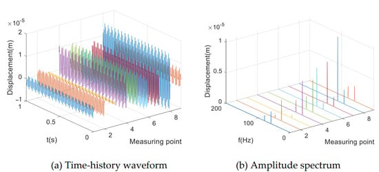
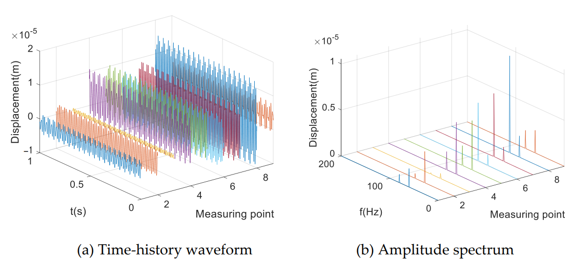
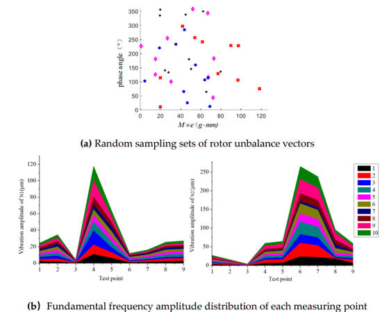
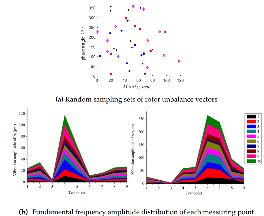
According to rotor dynamic balance standards, the allowable residual unbalance thresholds are specified as follows: fan rotor: 100 g·mm, high-pressure compressor rotor: 127 g·mm, and low-pressure and high-pressure turbine rotors: both 80 g·mm. This paper selects the first-stage fan disc (LPC1), fourth-stage high-pressure compressor disc (HPC4), high-pressure turbine disc (HPT), and low-pressure turbine disc (LPT) as research objects to elaborate the multi-disc unbalance simulation method. Figure 7 presents the vibration responses at each measurement point of the dual-rotor system under a specified unbalance vector. Furthermore, ten groups of combined unbalance vectors are generated via Monte Carlo sampling within the defined distribution bounds. The vibration amplitude acquired from the nine measuring points in these sampled cases is illustrated in Figure 8a. The corresponding results are shown in Figure 8b. It should be noted that these ten Monte Carlo samples serve as illustrative cases to demonstrate the response characteristics under combined multi-disc unbalance, rather than a sufficiently large sample set for rigorous statistical generalization over the full unbalance parameter space.
Figure 7.
Vibration response of the dual-rotor system with unbalance.
Figure 8.
Numerical vibration characteristics of the dual-rotor system with multi-disc multi-phase unbalance.
Simulation results show that vibration amplitude variation rules at all measuring points maintain consistent trends under different unbalance vector combinations. Low-pressure rotor unbalance imposes the most prominent influence on vibration signals collected at the low-pressure turbine disc (measuring point 4), and also generates non-negligible vibration excitation at intermediate supports and the high-pressure turbine disc. High-pressure rotor unbalance mainly excites obvious vibration at the high-pressure compressor disc (measuring point 6), with significant interference on intermediate bearing and low-pressure turbine vibration responses.
3.3. Vibration Response Analysis of Rotor System Under Support Misalignment Fault
The rear support point of the low-pressure turbine is jointly simulated using a squirrel cage and a “bushing” unit. Misalignment failure at the rear bearing of the low-pressure turbine rotor is reproduced by offsetting the installation position of the squirrel-cage flexible support. Considering the mechanical connection between the low-pressure turbine and fan rotor via coupling components, an extra torque load is applied on the coupling to characterize additional loads induced by misalignment. The simulation conditions are shown in Table 3.
Table 3.
Simulation parameters for the misalignment of the rear support point of the low-pressure turbine.
Spectral analysis of vibration signals collected under misalignment conditions reveals that second-order rotational frequency harmonics emerge at all measurement locations (Figure 9). In terms of vibration magnitude, the misalignment defect leads to the most significant vibration amplification at the rear bearing of the low-pressure turbine, while also introducing prominent perturbations to the vibration features of the high-pressure rotor.
Figure 9.
Numerical vibration characteristics of the dual-rotor system with support misalignment.
3.4. Vibration Response Analysis of Rotor System Under Rub-Impact Fault
Contact collision and friction forces between the rotor and stator are calculated using the built-in IMPACT function in ADAMS. The complete normal contact force Fn is expressed in Equation (1). The normal contact force contains two components: an elastic restoring force induced by mutual penetration of contact surfaces and a damping force related to the normal relative penetration velocity. The key parameters of this contact model include the contact stiffness k, radial rotor displacement x, nonlinear force exponent e, maximum damping coefficient Cmax, initial radial clearance δ0, and penetration depth d at which the damping reaches Cmax.
The tangential rubbing friction force Ft follows the Coulomb friction law coupled with the normal contact force, as shown in Equation (2):
where υt is the relative tangential sliding velocity between the rotor–stator contact surfaces, μ(υt) denotes the velocity-dependent friction coefficient to differentiate static and kinetic friction, and sign(⋅) represents the sign function determining the direction of tangential friction.
The physical meaning and selection criteria of key rub-impact parameters are given below. The radial clearance δ0 denotes the initial gap between the HPT disc and the fixed rubbing block. The contact stiffness k is calculated from the Hertz contact theory, using the elastic modulus, Poisson’s ratio, and equivalent contact radius of the HPT disc and rubbing block materials. The force exponent e = 1.5 is adopted for elastic metal point contact, consistent with the theoretical expectation. The friction coefficient μ is referenced from experimental data of identical material contact pairs. Contact damping Cmax represents energy loss during instantaneous impact and is set to 0.1% of contact stiffness, following the common practice in rotor localized rub-impact tests.
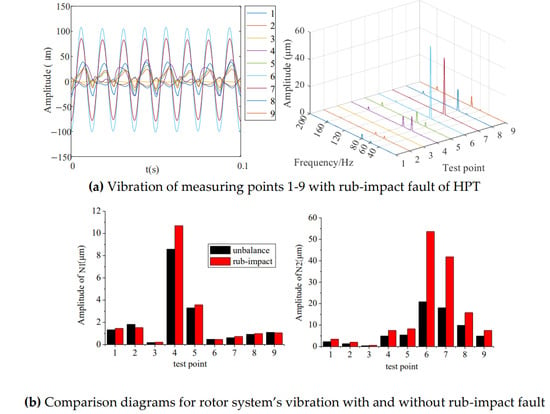
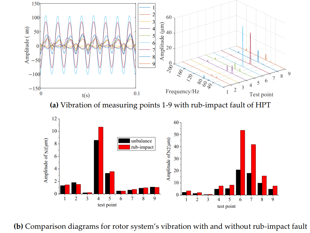
This paper simulates rub-impact faults occurring on a high-pressure turbine disc with calibrated contact parameters listed in Table 4, and collects time-domain waveforms and frequency spectrums of vibration signals at nine measuring points. Vibration responses of the dual-rotor system under mild rub-impact conditions are simulated with the first set of rub-impact parameters in Table 4, and the results are shown in Figure 10. It can be seen that the occurrence of rub impact on the high-pressure turbine disk introduces additional frequency components in the vibration spectrum beyond the fundamental rotational frequencies N1 and N2, among which the 2N2 component is the most prominent.
Table 4.
Simulation parameters for the rub-impact fault of the dual-rotor system.
Figure 10.
Numerical vibration characteristics of the dual-rotor system with rub-impact faults under the case I scenario.
Comparative analysis of rotational frequency vibration amplitudes before and after rubbing faults shows that stator–rotor collision significantly amplifies fundamental frequency vibration energy of the dual-rotor assembly. Rub-impact action occurring on the high-pressure turbine disc generates the strongest vibration excitation on the high-pressure turbine itself, followed by high-pressure compressor discs; meanwhile, vibration signals at the rear bearing of the low-pressure turbine also receive obvious interference from rubbing defects.
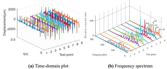
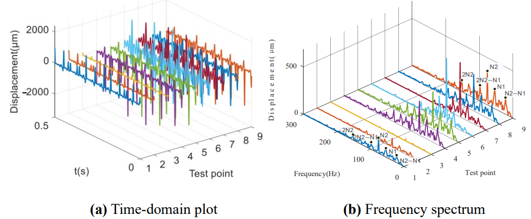
Severe rub-impact behaviour is realized by increasing the rub-impact stiffness and decreasing the initial rub clearance. The time-domain vibration waveforms and spectra at nine measuring points for this second case are illustrated in Figure 11. The spectrum contains many combination frequency components, including N2-N1, 2N2-N1, and 2N2.
Figure 11.
Numerical vibration characteristics of the dual-rotor system with rub-impact faults under the case II scenario.
4. Experiment
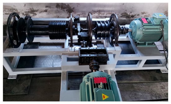
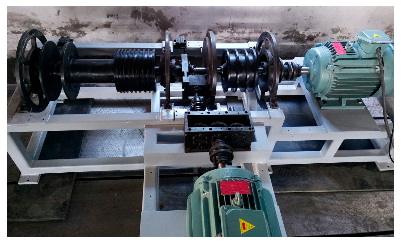
To further validate the rigid–flexible coupled dynamic model and vibration responses of the dual-rotor system, vibration tests were carried out on the dual-rotor test rig [30], and are shown in Figure 12.
Figure 12.
Test rig.
4.1. Critical Speed Measurement
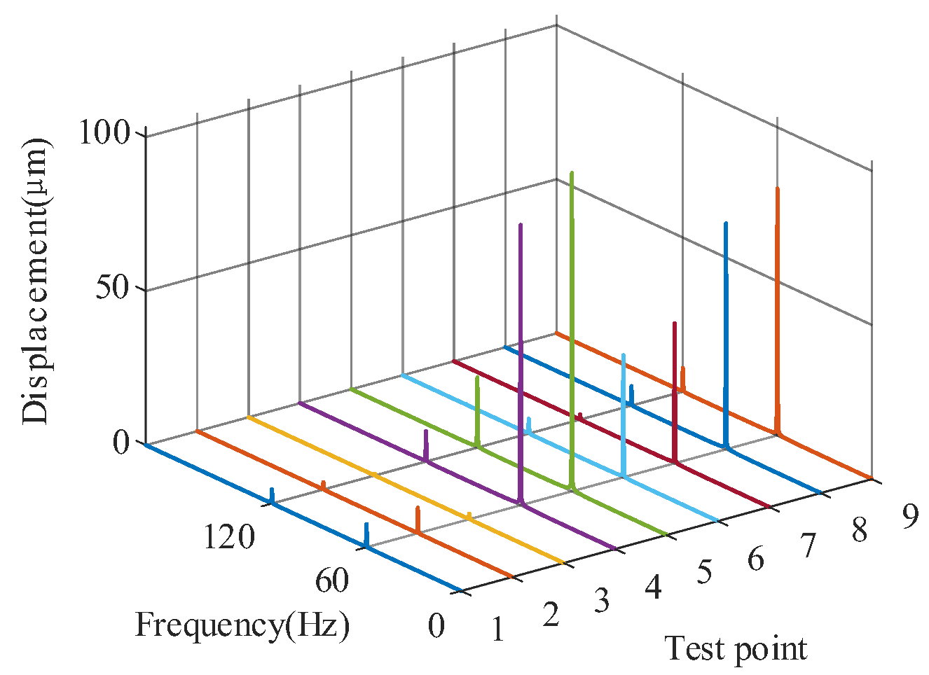
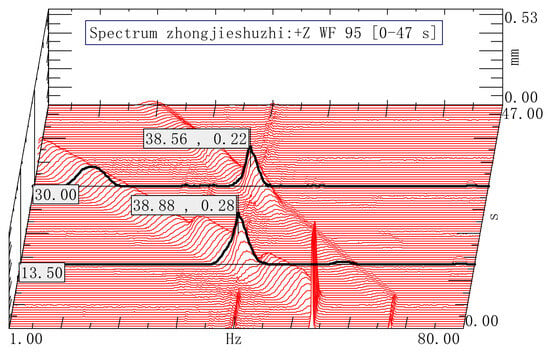
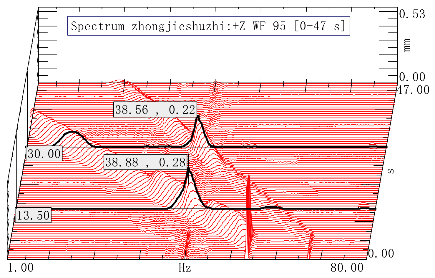
Vibration displacement responses of the dual-rotor system were measured using an LMS test platform and eddy-current sensors during the coast-down process from a steady speed of 4000 r/min. Three-dimensional waterfall spectra were constructed to characterize the system vibration behaviour, and the critical speeds were determined by extracting resonant peak frequencies together with the time–frequency spectral features captured throughout the coast-down process. Figure 13 shows the vibration response spectrum of the dual-rotor system acquired during deceleration. Resonance peaks appear at 38.56 Hz and 38.88 Hz in the spectral signals of the low-pressure and high-pressure rotors, respectively. In this work, 38.88 Hz is identified as the first-order critical frequency of the coupled dual-rotor system, which corresponds to a critical speed of 2332.8 r/min.
Figure 13.
Three-dimensional waterfall spectrum of vibration displacement of the coupled dual-rotor system under synchronous coast-down conditions.
The transient speed-sweep simulation yields three critical speeds of the dual-rotor system at around 2800 r/min, 4600 r/min, and 8200 r/min, while the coast-down experiment identifies a first-order critical speed of 2332.8 r/min. The deviation between the simulation and experiment is attributed to the simplifications of flexible supports, ignored bearing nonlinearity, assembly coaxiality errors, and additional structural damping existing in the test rig. Despite this deviation, the simulated first critical speed shows acceptable agreement with the experimental measurement, demonstrating that the proposed rigid–flexible coupled model can capture the primary resonant characteristics of the dual-rotor system.
4.2. Vibration Test of Rotor System Under Unbalance Fault
Unbalance of the dual-rotor system was simulated by adding mass blocks into prefabricated holes machined on the periphery of each disk, as shown in Figure 14.
Figure 14.
Unbalanced device.
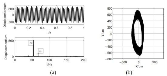
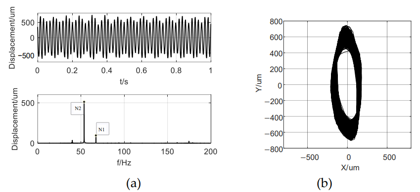
Vibration responses at the inter-shaft bearing were acquired under the operating conditions of nHP = 3150 r/min and nLP = 4000 r/min with a mass block of 17.5 g on the LPC, LPT, HPC, and HPT, as shown in Figure 15. The observable N1 and N2 frequency components within the vibration responses indicate the existence of vibration coupling between the inner and outer rotors.
Figure 15.
Inter-shaft bearing vibration responses under specified unbalance and rotational speeds: (a) Time-domain waveform and frequency spectrum; (b) Orbit of the rotor axis.
To investigate the effect of unbalance magnitude on the vibration characteristics of the dual-rotor system, time-domain vibration waveforms and frequency spectrum at the high-pressure turbine disk under four distinct unbalance magnitudes listed in Table 5 were obtained as shown in Figure 16.
Table 5.
Parameter setting for the unbalanced fault test.
Figure 16.
Vibration test under four unbalance settings.
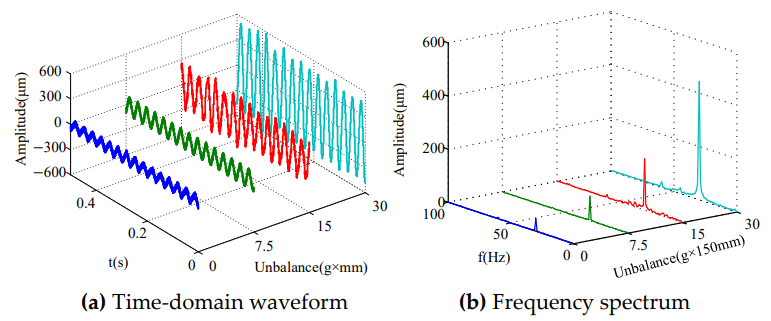
The vibration amplitudes at the N2 component are extracted and plotted in Figure 17, followed by a comparison with the simulation results under identical operating conditions. The analysis reveals that the vibration amplitudes obtained from the simulation are notably lower than those measured in the experiment. This discrepancy can be mainly attributed to two aspects. First, the stiffness and damping of joint interfaces, including bearings, couplings, and bolted connections, are simplified in the ADAMS model. Second, the numerical model only introduces the target fault excitation, ignoring extra excitations from motor torque ripple, foundation vibration, and residual unbalance of brackets in the test setup. But from the variation patterns of the results from both simulation and experience, it can be seen that the amplitude of N2 increases linearly with the increase in unbalance.
Figure 17.
Comparison of N2 amplitudes between experimental and simulated results.
4.3. Vibration Test of Rotor System Under Support Misalignment Fault
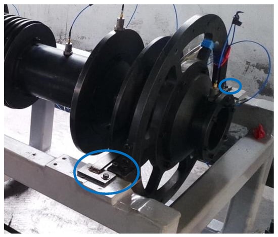
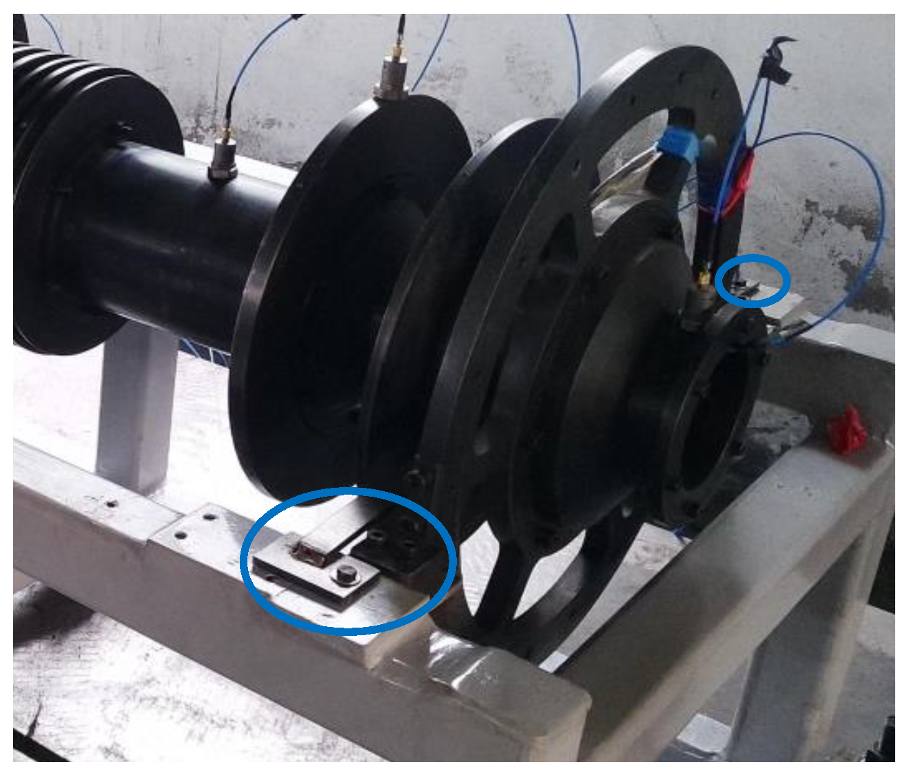
The misalignment simulation device is shown in Figure 18. Misalignment is simulated by adding shims at the support of the auxiliary plate.
Figure 18.
Support misalignment device.
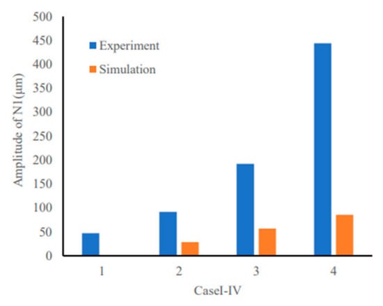
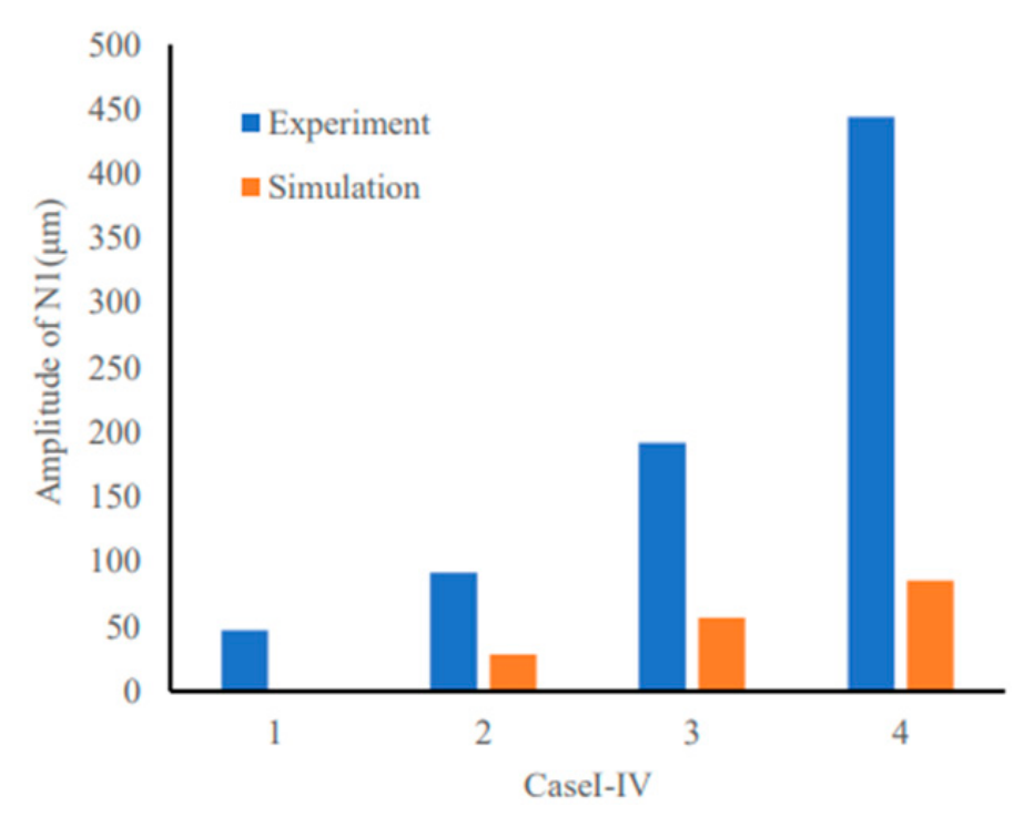
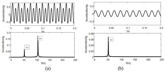
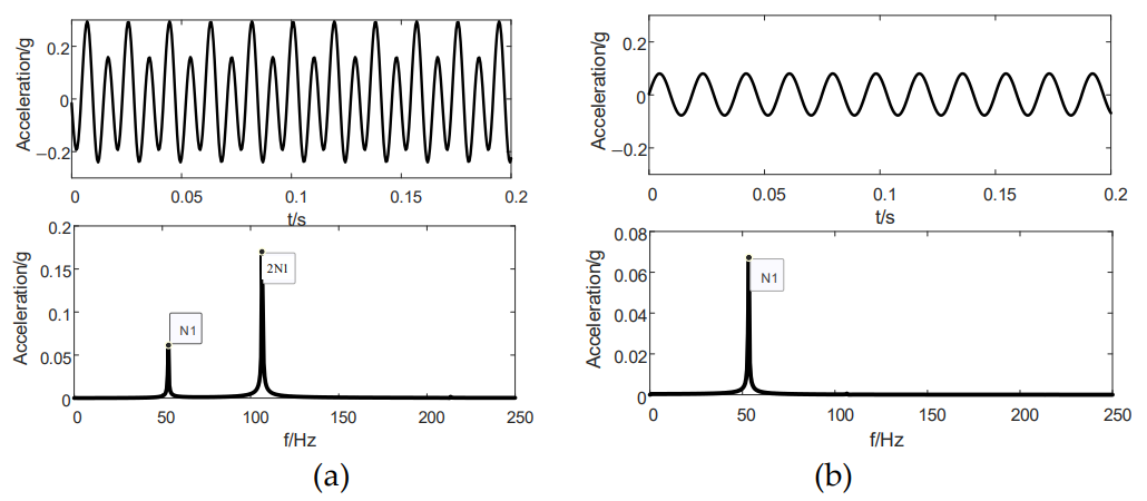
To investigate the vibration characteristics induced by support misalignment, a test case was configured with the high-pressure rotor stationary at 0 r/min and the low-pressure rotor running at 3200 r/min. An unbalance of 7.5 g × 125 mm was preset on the fan disk, and the rear support of the low-pressure turbine was elevated by 2 mm to introduce the misalignment fault. The vertical vibration acceleration time histories and spectra measured at the 6# auxiliary plate are plotted in Figure 19a, and these results are contrasted with the vibration responses excited merely by fan-disk unbalance (Figure 19b).
Figure 19.
Vertical vibration acceleration time histories and spectra at the 6# auxiliary plate: (a) with rear low-pressure turbine support misalignment; (b) without misalignment (only fan disk unbalance).
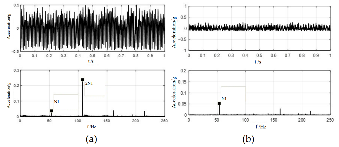
The spectral comparison demonstrates distinct differences between the two operating conditions. In the misalignment case, the second harmonic of the low-pressure rotational frequency (2N1) becomes the predominant spectral component at the 6# auxiliary plate. In the unbalance-only reference case, however, the 2N1 component is nearly negligible, and the low-pressure rotational frequency N1 dominates the spectrum instead. This comparison confirms that the support misalignment at the rear low-pressure turbine excites the 2N1 component in system vibration.
Time-domain waveforms and vibration acceleration spectra at the No. 6 conical shell (the component connecting the squirrel cage and auxiliary plate) were obtained under identical operating conditions shown in Figure 20. It should be clarified that the auxiliary plate is simplified as an ideally fixed boundary in the numerical model; hence, the vibration response of the conical shell is adopted for comparative analysis against experimental measurements. It can be seen that the support misalignment fault introduces the 2N1 harmonic component into the vibration spectrum at this measuring point. The amplitude of the N1 component predicted by the simulation is larger than the experimental value, while the amplitude of the 2N1 component is smaller than the measured result. This amplitude discrepancy mainly originates from the boundary simplification adopted in the simulation. In the numerical model, the auxiliary plate is rigidly constrained without considering assembly clearances and nonlinear contact behaviours at the connection interfaces. The experimental observations are consistent with the qualitative prediction of the established dual-rotor dynamic model. This agreement demonstrates that the present model can capture the core dynamic characteristic of support misalignment, i.e., this fault will induce the 2N1 harmonic in the vibration response.
Figure 20.
The simulation results of the vertical vibration acceleration time histories and spectra at the 6# cone shell: (a) with rear low-pressure turbine support misalignment; (b) without misalignment (only fan disk unbalance).
4.4. Vibration Test of Rotor System Under Rub-Impact Fault
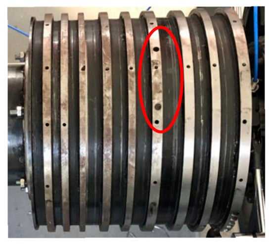
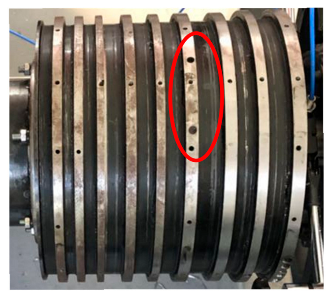
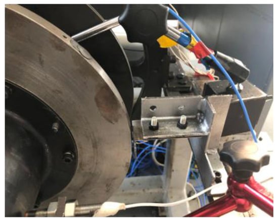
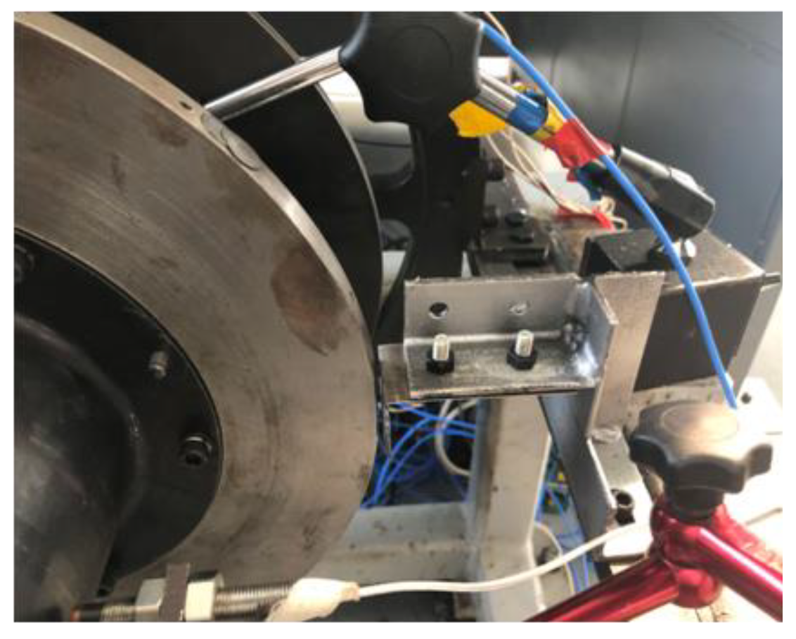
Figure 21 presents the test setup for rub-impact fault simulation. A rub rod was mounted on the bracket adjacent to the high-pressure turbine disk to produce fixed-point rub-impact results. The contact occurs between the rub rod and a protruding mass block installed at a predefined position on the high-pressure turbine disk.
Figure 21.
Rub-impact device.
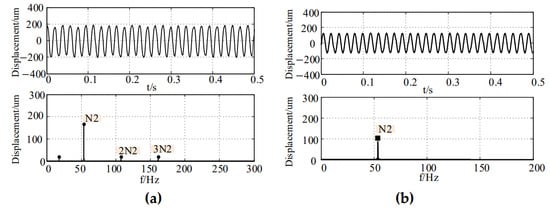
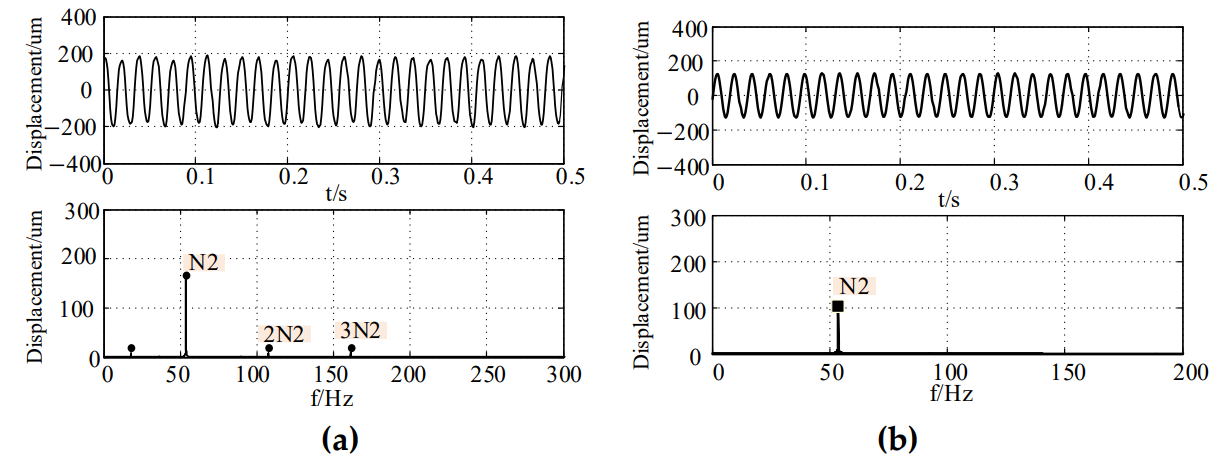
Vibration responses of rub impact on the high-pressure turbine disk were measured under the condition of the stationary low-pressure rotor and high-pressure rotational frequency (N2 = 52.5 Hz), with an unbalance of 3 g × 150 mm applied on the high-pressure turbine disk, as shown in Figure 22. A comparison of vibration responses acquired at the shaft measuring point of the 5# support for rub-impact and rub-free cases shows that the rub-impact fault introduces subharmonic and harmonic components of the rotational frequency in the vibration spectrum. In addition, the vibration amplitude of the fundamental frequency rises in the rub-impact direction.
Figure 22.
Vibration at intermediate support: (a) with HPT rub-impact fault; (b) without rub-impact fault (only HPT unbalance).
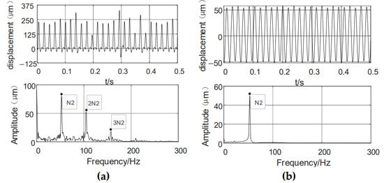
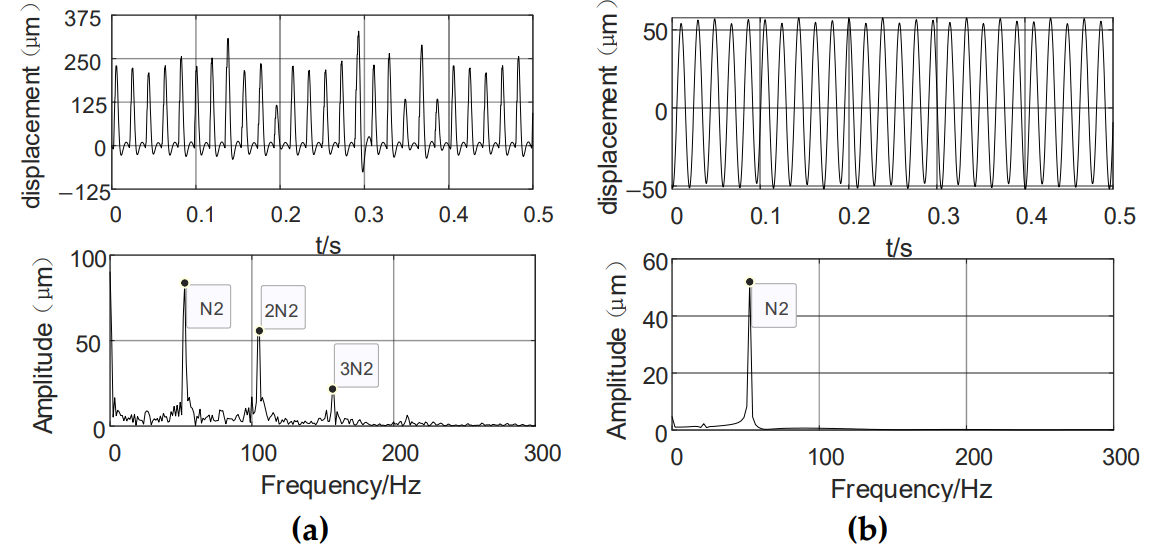
The measured responses are compared with the numerical results under identical operating conditions (Figure 23). It can be observed that the HPT rub-impact fault excites multiple harmonics of the rotational frequency N2 in the spectrum at this measurement point. The amplitude of the N2 component obtained from the simulation is lower than the experimental value, while the harmonic amplitudes of its multiples are higher than the measured counterparts.
Figure 23.
The simulation results of vibration at intermediate support: (a) with HPT rub-impact fault; (b) without rub-impact fault (only HPT unbalance).
This discrepancy is mainly related to the simplification of the rub-impact interface and boundary conditions in the numerical model. In the simulation, the rub-impact contact stiffness and damping are set as fixed parameters, and the supporting boundary is idealized. In the actual test, the local contact stiffness varies dynamically during intermittent rubbing. Meanwhile, the real contact process contains energy dissipation such as friction heat and material micro-abrasion, which suppresses the higher-order harmonic components compared with the numerical prediction. The consistent appearance of N2 multiple harmonics demonstrates that the present model can reproduce the core nonlinear dynamic feature induced by HPT rub-impact action, which supports the qualitative mechanism analysis of the rub-impact fault.
4.5. Isolated Excitation Scheme for Support Misalignment and Rub-Impact Tests
A single-rotor rotation configuration is adopted for the experimental tests of support misalignment and rub-impact faults to decouple fault excitation sources. Under synchronous dual-rotation conditions, fault signatures originating from the low-pressure and high-pressure rotors are superimposed and coupled, together with gyroscopic effects, which greatly hinders the extraction and interpretation of pure fault-induced vibration features. For the support misalignment fault introduced on the low-pressure rotor support, only the low-pressure rotor is driven to rotate while the high-pressure rotor remains stationary to eliminate undesired excitation. For the rub-impact fault occurring on the high-pressure turbine assembly, the low-pressure rotor is kept static to exclude its dynamic interference. This testing scheme achieves isolated fault excitation and facilitates the acquisition and analysis of vibration characteristics solely induced by the target fault.
5. Conclusions
This paper establishes a rigid–flexible coupled dynamic model for aeroengine dual-rotor systems, which distinguishes rigid attributes of fan and high-pressure rotors and flexible characteristics of low-pressure turbine shaft and squirrel-cage supports. This modelling scheme effectively avoids large calculation errors caused by improper body attribute simplification in conventional rotor dynamic analysis, provides a practical engineering modelling framework for dual-rotor assemblies, and lays a reliable numerical foundation for vibration characteristic analysis.
The proposed numerical model can accurately reproduce multi-disc multi-phase random unbalance, bearing misalignment, and stator–rotor rub-impact faults of rotor assemblies, and supports flexible parameter setting for various elastic bearing structures in simulation. Numerical simulations are carried out to capture the vibration response features under the three typical fault scenarios: (1) for the unbalance fault, the presence of both N1 and N2 components at all measurement points verifies the coupling behaviour between the inner and outer rotors. (2) For misalignment faults, the widespread occurrence of the 2N1 harmonic at all measuring locations demonstrates that misalignment at the rear support of the low-pressure turbine introduces the 2N1 component into the vibration responses of the dual-rotor system. (3) Rub-impact behaviour on the high-pressure turbine disk brings nonlinearity to the system, generating abundant combination frequency components in the vibration spectra of all measurement points; meanwhile, the occurrence of rub impact amplifies the vibration amplitudes at the fundamental rotational frequencies of the rotors.
Fault vibration experiments including unbalance, support misalignment, and fixed-point rub-impact tests are conducted on the dual-rotor test rig. The measured vibration responses under different fault conditions agree well with the core findings from numerical simulations: good consistency is observed in spectral harmonic features, rotor orbit morphologies, and nonlinear evolution trends of faults, whereas direct quantitative comparison of vibration amplitudes is not applicable due to mismatched operating speeds. Collectively, the numerical and experimental results validate that the proposed rigid–flexible coupled model exhibits satisfactory capability for simulating common rotor faults.
The simulated fault data generated by the ADAMS multi-body dynamic model can effectively capture the core nonlinear rubbing characteristics of the dual-rotor system, including amplitude modulation, frequency sidebands, and combined frequency components induced by rotor–stator contact and rotor–rotor coupling. Such simulated datasets provide abundant labelled samples under well-controlled operating conditions, which are expensive and difficult to acquire from full-engine flight tests. In this sense, the simulated data can act as a complementary data source to support fault feature extraction and the preliminary development of fault diagnosis algorithms.
Nevertheless, several inherent limitations remain when extending the present results to practical variable-speed flight envelopes. The current dynamic model adopts idealised boundary conditions. In real flight missions, aeroengines are subjected to time-varying inlet pressure and temperature, casing thermal deformation, pronounced gyroscopic effects, and aerodynamic excitations, which are not fully incorporated in the present model. These factors modulate the rubbing dynamic responses and redistribute fault features. Besides, the rotor–stator clearance adopted in the simulation is predefined and time-invariant, while the clearance field in a real engine is spatially non-uniform and varies with thermal expansion under different flight conditions. Furthermore, measurement noise from on-board sensors, vibration transmission attenuation, and signal aliasing in practical monitoring systems are simplified in numerical simulations. The mismatch between clean simulated signals and noisy flight measurement data may deteriorate the performance of data-driven diagnostic models trained solely on simulation datasets. Improving the dynamic model by introducing flight-state-dependent thermal and aerodynamic loads points out a promising direction for future work.
In this work, the comparison between simulation and experiment focuses on dynamic mechanisms and qualitative fault signatures, such as spectral harmonic components, rotor orbit morphologies, and nonlinear vibration trends, rather than absolute vibration amplitudes. The numerical model is capable of reproducing qualitative fault characteristics, whereas direct quantitative comparison of vibration magnitudes is invalid owing to the mismatched rotational conditions. In future work, we will attempt to identify a well-matched dual-speed operating point within the safe operating envelope of the rotor system to facilitate quantitative validation. Moreover, experiments considering support misalignment and rub-impact faults under synchronous dual-rotation conditions will be attempted to further explore the vibration characteristics under fault conditions.
Author Contributions
P.M.: Writing—Review and Editing, Writing—Original Draft Preparation Software, Conceptualization, and Methodology. Y.L.: Data Curation. Q.Z.: Resources and Funding acquisition. Q.H.: Resources and Software. All authors have read and agreed to the published version of the manuscript.
Funding
This research was supported by the National Natural Science Foundation of China (Grant Nos. 12502056 and 12402057).
Data Availability Statement
All data, models, and codes generated or used during the study appear in the submitted article.
Acknowledgments
This work was supported by Key Laboratory of Advanced Power Equipment Intelligent Manufacturing Technology, Shandong Province, and Key Laboratory of Vibration and Control of Aero-Propulsion System Ministry of Education, Northeastern University, Shenyang.
Conflicts of Interest
The authors declare no conflicts of interest in preparing this article.
Appendix A
Table A1.
The information on characteristic nodes of the finite element model for the dual-rotor system.
References
- Han, Q.; Ma, H. The research progress of rotor dynamics. J. Dyn. Control 2018, 16, 481–482. [Google Scholar]
- Zhang, D.; Liu, Y.; Liang, Z.; Ma, Y.; Hong, J. Prediction for Critical Speed of Double Spools System in Aero Engines. Propuls. Technol. 2015, 36, 292–298. [Google Scholar]
- Zhu, Q.; Han, S.; Yang, T.; Huang, X.; Han, Q. An Improved Transfer Learning Method for Rotor Unbalance Position Identification from Simulated Data to Experimental Data. Appl. Math. Model. 2024, 138, 115793. [Google Scholar] [CrossRef] [Scilit]
- Yang, X.; Luo, G.; Tang, Z.; Wang, F. Modeling method and dynamic characteristics of high-dimensional counter-rotating dual rotor system. J. Aerodyn. 2014, 29, 585–595. [Google Scholar]
- Zhang, D.; Zen, Z. Development of an integrated multifunctional rotor dynamics experimental platform for our research. Exp. Technol. Manag. 2023, 40, 133–137. [Google Scholar]
- Xu, K.; Zhang, L. Improvement of the overall transfer matrix method for solving the critical speed of a dual rotor system. J. Nav. Aviat. Eng. Coll. 2013, 28, 133–136. [Google Scholar]
- Wang, P.; Zhao, X.; Yang, Y.; Ma, H.; Han, Q.; Luo, Z.; Li, X.; Wen, B. Dynamic modeling and analysis of two-span rotor-pedestal system with bearing tilt and extended defect: Simulation and experiment. Appl. Math. Model. 2024, 125, 1–28. [Google Scholar] [CrossRef] [Scilit]
- Zou, C.; Zhai, J.; Han, Q. Analysis of the similarity design and vibration transmission characteristics of typical support structures of an aero-engine. Proc. Inst. Mech. Eng. Part C J. Mech. Eng. Sci. 2022, 236, 9441–9458. [Google Scholar] [CrossRef] [Scilit]
- Liu, J.; Wang, C.; Luo, Z. Research nonlinear vibrations of a dual-rotor system with nonlinear restoring forces. J. Braz. Soc. Mech. Sci. Eng. 2020, 42, 6–20. [Google Scholar] [CrossRef] [Scilit]
- Wang, N.; Xu, H.; Jiang, D. Dynamic Model and Fault Feature Research of Dual-Rotor System with Bearing Pedestal Looseness. Math. Probl. Eng. 2016, 2016, 1–18. [Google Scholar] [CrossRef] [Scilit]
- Hou, S.L.; Hou, L.; Chen, Y. The influence of intermediate bearing positioning deviation on the dynamic characteristics of a dual rotor system. Mech. Mach. Theory 2023, 184, 105262. [Google Scholar] [CrossRef] [Scilit]
- Wang, T.; Liu, C. Progress in Multibody Dynamics and Aerospace Dynamics and Their Control. J. Dyn. Control 2018, 65, 3–4. [Google Scholar]
- Li, Y.; Wang, H.; Zhang, L. Rigid-Flexible Multi-Body Dynamic Modeling and Mesh Independence Verification for Aeroengine Dual-Rotor Assemblies. J. Comput. Nonlinear Dyn. 2025, 20, 081007. [Google Scholar]
- Zhao, J.; Ma, H.; Liu, Y. Nonlinear Vibration Response of Dual-Rotor Systems Under Combined Support Misalignment and Multi-Disc Random Unbalance. J. Comput. Nonlinear Dyn. 2023, 18, 111006. [Google Scholar]
- Prabith, K.; Krishna, I. Rub-Impact Nonlinear Dynamics of Counter-Rotating Dual-Rotor Systems With Elastic Squirrel-Cage Supports. J. Comput. Nonlinear Dyn. 2022, 17, 061004. [Google Scholar]
- Yang, T.; Ma, H.; Qin, Z.; Guan, H.; Xiong, Q. Coupling vibration characteristics of the shaft-disk-drum rotor system with bolted joints. Mech. Syst. Signal Process. 2022, 169, 108747. [Google Scholar] [CrossRef] [Scilit]
- Xu, H.; Yang, Y.; Ma, H.; Luo, Z.; Li, X.; Han, Q.; Wen, B. Vibration characteristics of bearing-rotor systems with inner ring dynamic misalignment. Int. J. Mech. Sci. 2022, 230, 107536. [Google Scholar] [CrossRef] [Scilit]
- Ma, Z.; Zhao, X.; Wu, Y.; Ma, H.; Cao, P.; Guan, H.; Liu, Z.; Fan, C.; Zhu, J.; Yan, P.; et al. Two novel indicators for gear crack diagnosis based on vibration responses: Experiment and simulation. Mech. Mach. Theory 2025, 205, 105905. [Google Scholar] [CrossRef] [Scilit]
- Chen, Y.; Hou, L.; Chen, G.; Song, H.; Lin, R.; Jin, Y. Nonlinear Dynamics Analysis of a Dual-Rotor-Bearing-Casing System Based on a Modified HB-AFT Method. Mech. Syst. Signal Process. 2023, 185, 109805. [Google Scholar] [CrossRef] [Scilit]
- Zuo, G. Combination resonance and primary resonance characteristics of a dual-rotor system under the condition of the synchronous impact of the inter-shaft bearing. Sci. Rep. 2023, 13, 1153. [Google Scholar] [CrossRef] [Scilit] [PubMed]
- Nan, G.; Hu, J.; Yao, X.; Zhang, B. Modeling and Nonlinear Dynamic of Dual-Rotor System With Misalignment During Aircraft Climbing Flight. Shock Vib. 2026, 2026, 6327946. [Google Scholar] [CrossRef] [Scilit]
- Liu, M.; Yang, H.; Wang, Y. Beam-shell coupled dynamic modeling and verification for an aeroengine dual-rotor system. J. Vib. Meas. Diagn. 2024, 44, 712–719. [Google Scholar]
- Wang, X.; Zhang, Y. Modeling and Contribution Analysis of Vibration Transfer Paths for a Dual-Rotor Aeroengine. J. Aerosp. Eng. 2024, 37, 04024078. [Google Scholar] [CrossRef] [Scilit]
- Yi, H.; Hou, L.; Gao, P.; Chen, Y. Nonlinear resonance characteristics of a dual-rotor system with a local defect on the inner ring of the inter-shaft bearing. Chin. J. Aeronaut. 2022, 35, 182–197. [Google Scholar] [CrossRef] [Scilit]
- Yao, X.; Nan, G.; Li, Y.; Qiu, X. Nonlinear dynamic characteristics of dual-rotor system under combined misalignment and rub-impact faults. Int. J. Non-Linear Mech. 2025, 172, 104928. [Google Scholar]
- Lin, W.; Wang, C. Nonlinear vibration characteristics of inter-shaft rub-impact in aero-engine dual-rotor system. Propuls. Technol. 2023, 44, 847–856. [Google Scholar] [CrossRef] [Scilit]
- Jin, Y.; Liu, Z.; Chen, Y. Blade-casing rubbing response analysis of a dual-rotor system considering bearing nonlinearity and misalignment. Chin. J. Aeronaut. 2024, 37, 234–249. [Google Scholar]
- Zhang, Y.; Li, Y. Dynamic characteristics of dual-rotor system considering Alford force and nonlinear inter-shaft bearing. Int. J. Mech. Sci. 2025, 289, 110056. [Google Scholar]
- Bukvić, M.; Vencl, A.; Milojević, S.; Skulić, A.; Gajević, S.; Stojanović, B. The Influence of Carbon Nanotube Additives on the Efficiency and Vibrations of Worm Gears. Lubricants 2025, 13, 327. [Google Scholar] [CrossRef] [Scilit]
- Ma, P. Research on Vibration Characteristics of Aeroengine Dual-Rotor System. Master’s Thesis, Dalian University of Technology, Dalian, China, 2026. [Google Scholar]

Disclaimer/Publisher’s Note: The statements, opinions and data contained in all publications are solely those of the individual author(s) and contributor(s) and not of MDPI and/or the editor(s). MDPI and/or the editor(s) disclaim responsibility for any injury to people or property resulting from any ideas, methods, instructions or products referred to in the content. |
© 2026 by the authors. Licensee MDPI, Basel, Switzerland. This article is an open access article distributed under the terms and conditions of the Creative Commons Attribution (CC BY) license.