


Abstract
Flux-switching permanent-magnet (FSPM) machines feature high torque density and a mechanically robust rotor structure, making them suitable for high-speed applications. However, the stator-mounted permanent magnets (PMs) are exposed to rich spatial and temporal flux harmonics, which induce substantial eddy-current losses, increase the risk of irreversible demagnetization, and reduce operational reliability. Although finite-element analysis (FEA) offers high accuracy, its computational cost is considerable. Conventional equivalent magnetic network (EMN) methods are computationally efficient but have difficulty directly representing the eddy-current reaction field, which can limit prediction accuracy. This paper proposes a hybrid vector magnetic network (VMN) model based on the magductance principle. A rotor-saliency-modulated air-gap magnetomotive-force (MMF) model avoids repeated network reconstruction, while frequency-dependent magductance branches incorporate PM eddy-current coupling directly into the network without a separate post-processing correction. A three-dimensional PM subnetwork is combined with Schur-complement condensation to represent axial eddy-current distributions while reducing the system matrix order. Validation on a 12-slot/10-pole, 10 kW prototype shows maximum torque deviations of 1.9% relative to measurement and 2.0% relative to 3D FEA. Compared with 2D and 3D FEA, the computational speed is increased by approximately 15 and 280 times, respectively. The proposed model provides an efficient tool for PM-loss evaluation and segmentation assessment in the investigated FSPM machine.
1. Introduction
Flux-switching permanent-magnet (FSPM) machines have attracted considerable attention because of their high torque density, mechanically robust rotor structure, and suitability for high-speed operation [1,2]. Representative FSPM variants include axial-field and hybrid permanent-magnet (PM) configurations [3,4]. However, in stator-PM configurations with concentrated windings, the magnets are exposed to rich spatial and temporal flux harmonics. These harmonics induce substantial eddy-current losses (ECLs) [5], increase PM temperature, and may lead to irreversible demagnetization [6,7,8,9]. Accurate and efficient prediction of PM eddy-current losses is therefore important for design-stage comparison and optimization.
Finite-element analysis (FEA) remains a reference tool for electromagnetic analysis, but its computational cost can limit repeated multiparameter optimization [10,11]. Equivalent magnetic network (EMN) methods reduce model size and can represent leakage flux and local saturation through discretized or nonlinear magnetic networks [12,13,14,15,16,17]. Related studies include equivalent reluctance networks for reproducing magnetic-field and torque quantities, as well as multilayer quasi-three-dimensional equivalent models for accelerating 3D analysis [18,19]. However, conventional EMN models often require air-gap permeance recalculation or network reconnection at each rotor position, while PM eddy-current reaction is commonly treated through simplified loss post-processing.
Vector magnetic-circuit EMNs and PM-loss network models have addressed some of these limitations by introducing magductance, eddy-current reaction-field coupling, and high-frequency harmonic effects [20,21,22]. More recently, Wang et al. [23] introduced magductance elements into a 2D finite-element model of an FSPM machine and used equivalent windings to represent PM eddy-current reaction and segmentation effects. Hoang et al. [24] proposed an analytical framework in 2026 that combines magnetostatic and frequency-domain models to account for magnetic saturation and magnetic diffusion in conductors when calculating rotor eddy-current losses in permanent-magnet synchronous machines. These studies further demonstrate the importance of considering saturation and eddy-current reaction simultaneously in reduced-order models. Network models can approach FEA accuracy while substantially reducing computational cost. Nevertheless, for FSPM machines, a compact model that avoids rotor-position-dependent topology reconstruction, embeds eddy-current reaction in the magnetic network, and retains axial PM segmentation paths while reducing system order remains to be further developed.
To address these issues, this paper proposes a hybrid-dimensional vector magnetic network (VMN) based on rotor-field modulation and vector magnetic-circuit theory. The main contributions are as follows.
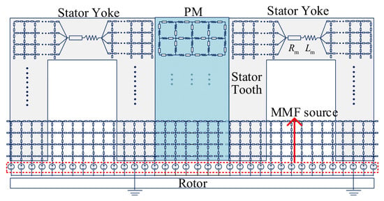
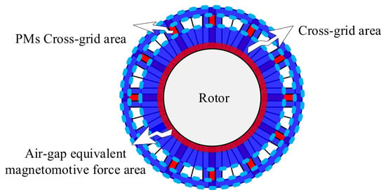
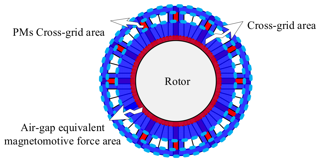
- A hybrid VMN framework based on the magductance principle is proposed, as shown in Figure 1. Unlike conventional EMN methods, the proposed model embeds the PM eddy-current reaction field directly into the network branches, thereby representing frequency-dependent eddy-current coupling. It does not rely on empirical correction coefficients and improves the prediction of high-order-harmonic PM eddy-current losses in FSPM machines.Figure 1. Structure of the proposed VMN.
- A rotor-saliency-modulated air-gap MMF model is established. By introducing the modulation mechanism of the rotor saliency, the time-varying air-gap flux distribution during rotor rotation can be obtained without repeatedly reconstructing the network topology at different rotor positions. This substantially simplifies dynamic solution procedures and improves the computational efficiency of transient electromagnetic analysis.
- A three-dimensional PM subnetwork containing axial magductance branches is constructed to represent the three-dimensional spatial characteristics of eddy currents inside the magnets. The system matrix is then compressed using Schur-complement condensation, which eliminates redundant interior-node degrees of freedom while retaining the essential three-dimensional eddy-current coupling. This reduction strategy lowers the matrix order and computational cost while balancing prediction accuracy and solution speed.
2. Materials and Methods
2.1. Study Case
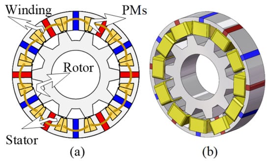
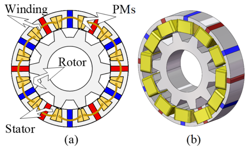
A 12-slot/10-pole, 10 kW FSPM machine is investigated. Its topology is shown in Figure 2, and its key structural parameters are listed in Table 1. The prediction accuracy and computational efficiency of the proposed model are evaluated by comparison with a conventional EMN, 2D and 3D FEA, and prototype measurements.
Figure 2.
Topology of the FSPM machine: (a) 2D cross-section; (b) 3D view.
Table 1.
Key parameters of the FSPM machine.
As shown in Figure 2, the machine has an inner-rotor structure. The stator consists of circumferentially arranged U-shaped laminated iron-core segments, with PMs embedded between adjacent segments. The armature winding is concentrated, with four coils connected in series per phase. Both the PMs and armature windings are mounted on the stator. The rotor is a salient iron core with ten teeth and slots between adjacent teeth; it carries neither PMs nor excitation windings. Figure 2a shows the cross-sectional arrangement of the stator, rotor, PMs, and windings, while Figure 2b presents the corresponding three-dimensional structure.
2.2. Equivalent Air-Gap MMF Calculation Based on Rotor-Field Modulation
The PM excitation MMF Fpm is expressed as follows [11]:
where Fpm0 is the amplitude of the rectangular-wave PM excitation MMF, fpmν is the coefficient of the νth harmonic of the PM MMF, ν = 2k + 1 denotes an odd harmonic order, k is a nonnegative integer, pf is the number of PM pole pairs, α is the PM pole-arc coefficient, and Nst is the number of stator slots.
The armature MMF FABC(ϕ, t) generated by the armature currents is expressed as follows:
where ia, iβ, and ic are the stator phase-A, phase-B, and phase-C currents, respectively, and WsA(φ), WsB(φ), and WsC(φ) are the corresponding phase winding functions. The number of series-connected coils per phase, Nc, follows the definition in Table 1.
For a smooth stator and a slotted rotor, the rotor-saliency-based permeance-modulation function Mr(Nrt, εr) is expressed as follows:
where mr0 and mrl are the mean value and the lth harmonic coefficient of the rotor permeance-modulation function, respectively; l is a positive integer; εr = or/tr is the ratio of rotor-slot opening to rotor-tooth pitch; or is the rotor-slot opening; tr is the rotor pitch used in the modulation model; kcr is the rotor Carter coefficient; g is the air-gap length; βr is the slotting-effect coefficient describing the reduction in air-gap flux density caused by rotor slotting; and ωm is the mechanical angular velocity of the rotor. The rated speed in Table 1 is denoted by nr. The air-gap length g is the difference between the stator inner radius si and rotor outer radius ro.
Virtual rotor rotation is emulated by calculating the rotor-modulated air-gap MMF, eliminating the need to reconnect nodes at each rotor position. The resultant air-gap MMF is obtained by superimposing the PM and armature MMFs [25,26,27]:
2.3. Stator-Core Branch Parameters
According to vector magnetic-circuit theory, magductance elements are introduced in addition to conventional reluctance elements to quantitatively represent the reaction of core eddy currents on magnetic flux [21,25,28,29].
2.3.1. Stator-Core Yoke
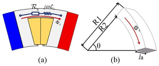
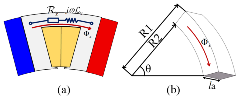
As illustrated in Figure 3, the stator-core yoke is represented by a reluctance–magductance branch in the VMN. x and x denote the reluctance and magductance of branch x, respectively, and ω = 2πf is the angular frequency of the time-varying flux.
Figure 3.
Vector branch model of the stator yoke: (a) equivalent magnetic branch; (b) geometric parameters.
For simplicity, the stator-core yoke shown in Figure 3b is modeled as a concentric annular region with an arc-shaped cross-section. The corresponding yoke reluctance x is as follows:
where μx is the permeability of branch x and θ is the central angle in radians. The outer yoke radius is so, as defined in Table 1. The inner yoke radius is denoted by γ, which corresponds to the inner boundary of the yoke at the slot bottom and is distinct from the stator bore radius si.
The yoke magductance is calculated as follows:
where a is the lamination thickness, which is distinct from the PM pole-arc coefficient α. The resistivity ρ(T) of the laminated core material is corrected for temperature as follows:
where T0 is the reference temperature, T is the core temperature at the rated operating point, and αc is the temperature coefficient.
The magnetic-admittance parameters of the xth stator-yoke branch are calculated as follows:
where x, 𝒵x, Gx, and x denote the magnetic admittance, magnetic impedance, permeance, and magnetic susceptance of the stator-yoke branch, respectively.
2.3.2. Stator-Core Teeth
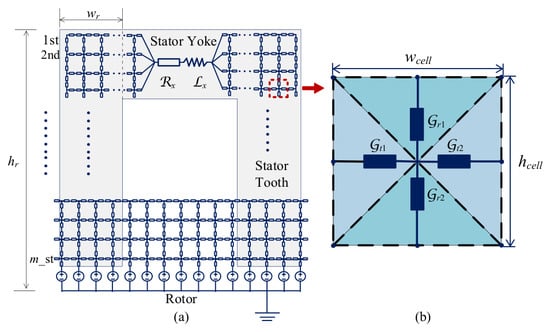
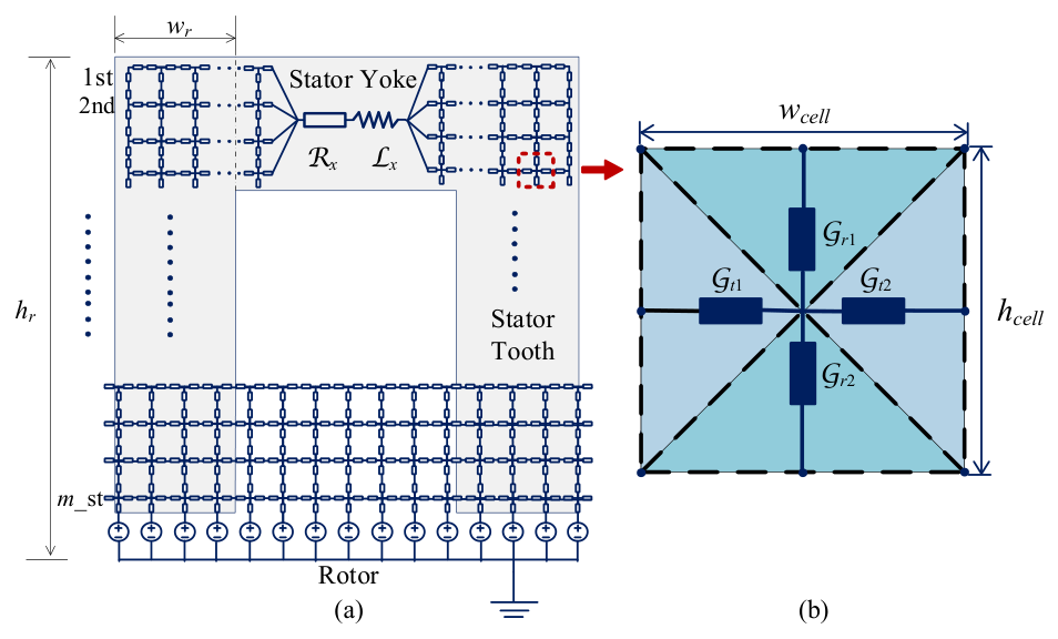
To resolve the radial and tangential flux components in the stator teeth, a cross-shaped mesh is adopted in the VMN. As shown in Figure 4, rs and ts denote the radial and tangential magnetic admittances of the stator teeth, respectively.
Figure 4.
Stator discretization: (a) overall mesh; (b) cross-shaped mesh element.
The radial reluctance rs of the mesh element shown in Figure 4b is as follows:
where μ0 and μr are the permeability of free space and the relative permeability, respectively. A rectangular stator region with width wr, height hr, and axial length la is divided into m rows and n columns. The dimensions of each cell are as follows:
When eddy-current effects are considered, the radial magductance parameter rs is as follows:
where δ is the skin depth, σs is the electrical conductivity of the stator material, and ωs is the angular frequency used for the stator-core branch. wcell and hcell are the local cell dimensions defined in Equation (13).
The radial complex magnetic admittance rs is as follows:
The tangential reluctance ts of the mesh shown in Figure 4b is as follows:
When eddy-current effects are considered, the tangential magductance parameter ts is as follows:
The tangential complex magnetic admittance ts is as follows:
When a mesh element is located on the boundary of the modeled region, its effective cross-sectional area is halved. The boundary magnetic admittances ′rs and ′ts are therefore corrected as follows:
2.4. PM Branch Parameters
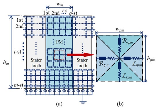
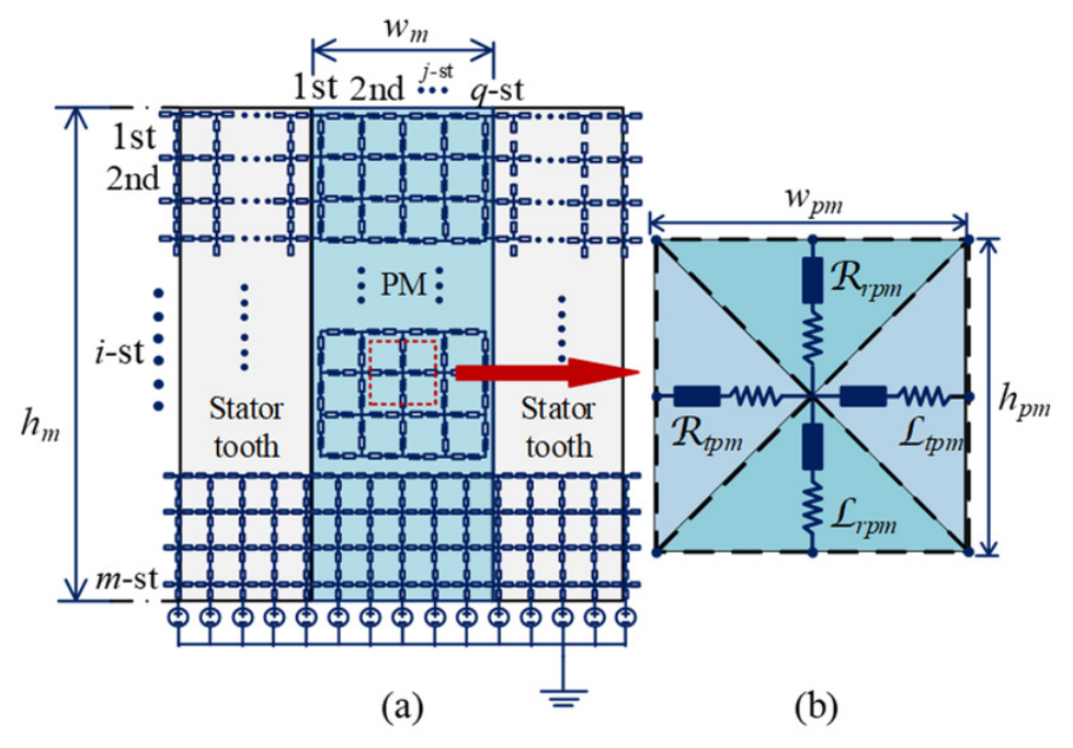
The reluctance of a PM mesh element is calculated using the same method as that for the stator teeth. The radial reluctance rpm and tangential reluctance tpm are as follows:
where μpm is the recoil permeability of the PM, and wpm and hpm are the width and height of the PM mesh element shown in Figure 5b, respectively. A PM region with circumferential width wp and radial height hp is divided into q circumferential columns and m radial rows. The dimensions of an individual PM cell are as follows:
where q and m denote the numbers of circumferential columns and radial rows, respectively. The overall PM dimensions hp and wp follow the definitions in Table 1.
Figure 5.
PM discretization: (a) PM mesh; (b) cross-shaped PM mesh element.
Variations in the air-gap magnetic field induce eddy currents inside the PMs. To represent the eddy-current reaction in the magnets, magductance elements are introduced, as shown in Figure 5. Each PM is modeled as an annular-sector conductor, and radial and tangential magductance models are established separately. The radial PM magductance is as follows:
where σpm is the electrical conductivity of the PM, rpm(i) is the representative radius of the ith radial row, and Ξr(Ωr) is the radial skin-effect correction factor. The superscript (i,j) indicates that the PM cell is located in the ith radial row and jth circumferential column.
The radial frequency parameter Ωr, skin depth δr, and diffusion wavenumber kr are defined as follows:
The radial correction factor Ξr(Ωr) used in Equation (23) is as follows:
where rin(i) is the inner radius of the electrically connected PM region at the ith radial row and must therefore be updated for the current row rather than treated as a fixed global radius. I0(·) and I1(·) are modified Bessel functions of the first kind. The radial complex magnetic admittance is as follows:
where and rpm are the radial permeance and magnetic susceptance, respectively.
For the tangential branch, the PM magductance is as follows:
where accounts for the curvature of the annular sector, and Ξt(Ωt) is the tangential skin-effect correction factor. The corresponding frequency parameter Ωt, skin depth δt, and diffusion wavenumber kt are as follows:
The normalized tangential skin-effect correction factor Ξt(Ωt), corresponding to diffusion along the radial cell height, is as follows:
The correction factor Ξt(Ωt) is normalized so that it approaches unity as Ωt tends to zero. Thus, Equation (29) recovers the low-frequency tangential magductance while retaining high-frequency diffusion effects.
The corresponding cell-wise curvature factor is as follows :
where rout(i) is the outer radius of the ith radial row. These local cell radii are defined separately from the machine-level stator and rotor boundary radii in Table 1 and are not interchangeable with them.
The tangential complex magnetic admittance is as follows:
where and tpm are the tangential permeance and magnetic susceptance, respectively. At a cell boundary, the half-area branch convention in Section 2.3 is applied: the series reluctance and magductance are doubled, and the resulting magnetic admittance is halved:
2.5. Three-Dimensional Extension with Axial Branches
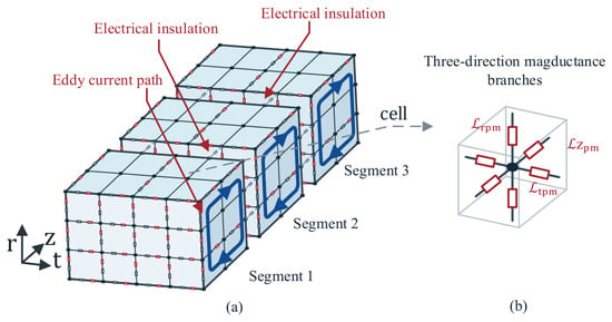
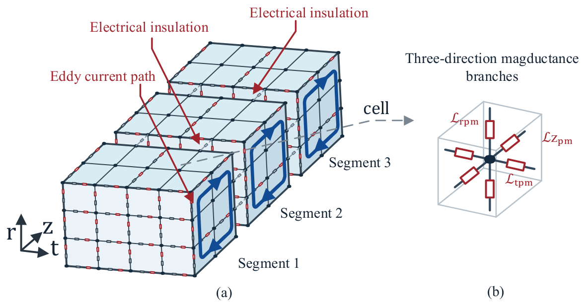
A complete three-dimensional VMN is obtained by adding an axial branch to each radial–tangential PM cell. The axial reluctance zpm and magductance zpm use the same local dimensions wpm and hpm shown in Figure 6.
Figure 6.
Three-dimensional mesh discretization of the PM.
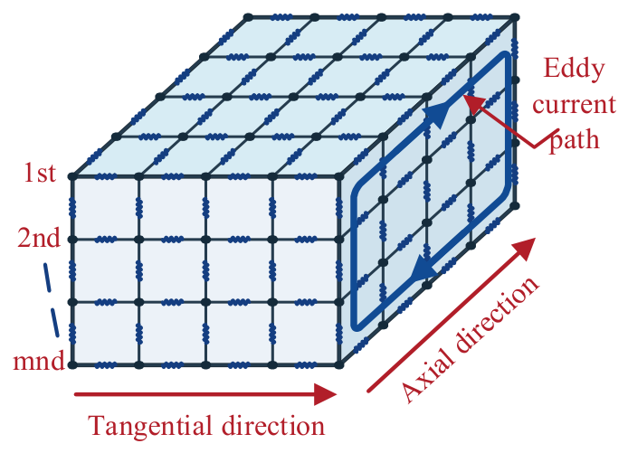
As shown in Figure 7, mesh discretization is a numerical operation and does not imply electrical insulation between all mesh cells. For three-segment axial segmentation, electrical insulation is introduced at the two physical segment interfaces, interrupting conducting connections across the interfaces so that eddy currents close only within each segment; adjacent cells within the same segment remain electrically connected. The same principle is applied to radial segmentation, with insulating interfaces placed at the radial segment boundaries. The interrupted links are electrical-conduction paths, whereas magnetic coupling across the insulating interfaces is retained through the corresponding reluctance branches.
Figure 7.
Three-dimensional mesh of an axially three-segmented PM: (a) intra-segment eddy-current paths; (b) schematic of the three directional magductance branches.
The blue closed loops in Figure 7 represent eddy currents induced by time-varying radial flux, which primarily circulate in the tangential–axial plane; axial insulation limits the axial extent of these loops. Similarly, eddy currents induced by tangential and axial flux variations circulate in the radial–axial and radial–tangential planes, respectively. The radial, tangential, and axial magductances rpm, tpm, and zpm represent the eddy-current reaction associated with the corresponding flux directions. The magductance branches are equivalent magnetic-network elements, not physical current-carrying wires. The axial mesh-layer thickness Δz is a numerical discretization dimension and should not be confused with the length of a physical insulating segment.
The axial PM reluctance is determined by the cell cross-sectional area and axial layer thickness:
where Δz is the axial layer thickness and μpm,i is the relative recoil permeability assigned to the axial layer or insulating interface.
For a time-varying axial flux, the corresponding eddy-current reaction is represented by the axial PM magductance :
where is the axial PM magductance.
The three directional branch pairs, (rpm, rpm), (tpm, tpm), and (zpm, zpm), form a local three-dimensional PM cell for the nodal VMN.
2.6. VMN Assembly and Solution
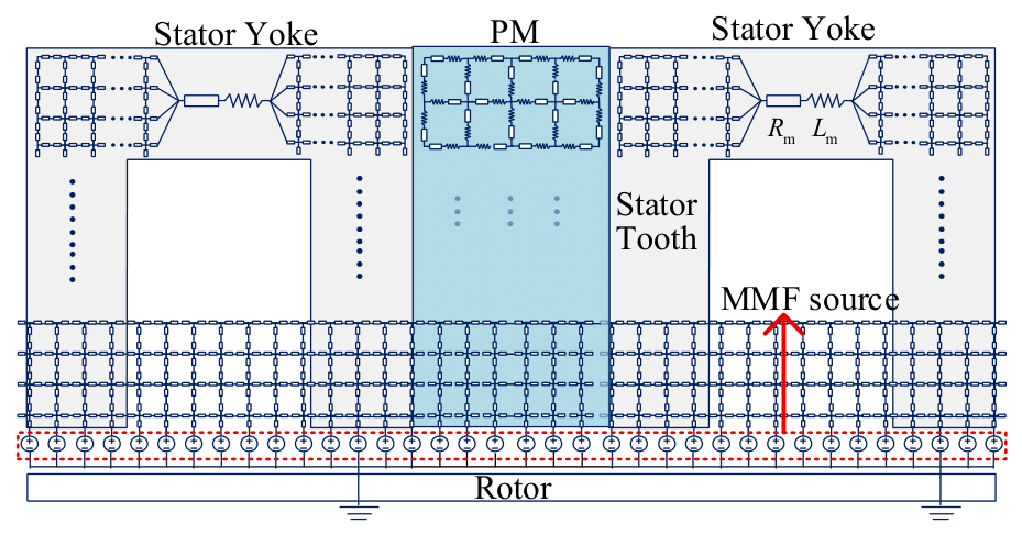
The overall VMN of the FSPM machine shown in Figure 8 combines lumped magnetic circuits with mesh discretization. The stator yoke is represented by lumped-parameter magnetic branches, whereas the stator teeth and air-gap region use a cross-shaped reluctance mesh. Each stator tooth is divided into a 3 × 4 mesh to represent saturation and leakage flux. The PM region is divided into an 8 × 4 × 6 mesh for eddy-current-loss calculation. A total of 240 MMF sources are uniformly distributed around the air-gap circumference, corresponding to 24 sources per rotor-tooth pitch. The system is solved using the nodal MMF method.
Figure 8.
Overall VMN of the FSPM machine.
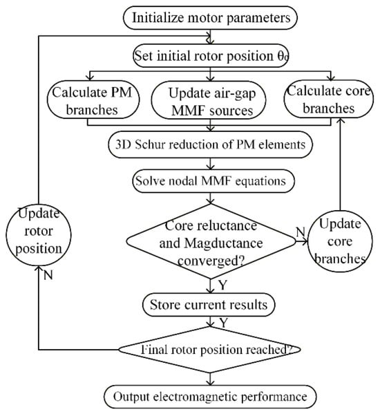
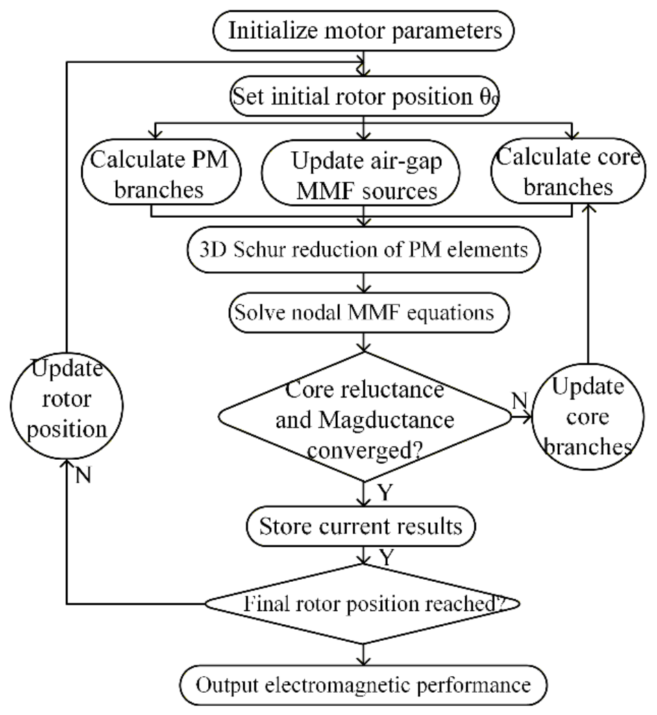
As shown in Figure 9, the rotor position is first specified, and the impedances of the core and PM branches are calculated to initialize the VMN. At each rotor position, the equivalent air-gap MMF sources are updated according to Section 2.2, and the material-dependent branch parameters are updated through reluctance–magductance iteration. During one electrical period of rotor operation, the reference air-gap permeance and network connectivity remain unchanged. With the current material-dependent branch parameters, the global nodal equation is as follows:
where is the sparse, symmetric global nodal magnetic-admittance matrix, m is the vector of unknown nodal MMF phasors, and Φ is the equivalent nodal flux-source vector assembled from the branch excitations.
Figure 9.
Computational flowchart of the complete VMN model.
To account for axial PM segmentation, a three-dimensional magnetic-admittance network is constructed for the PMs. To reduce computational cost, the stator-core magnetic network remains two-dimensional. Therefore, before the global solution, each three-dimensional PM macro-cell is condensed using the Schur complement so that the three-dimensional PM network can be coupled to the two-dimensional stator-core network. The local nodal MMF degrees of freedom are divided into boundary nodes, which connect to the surrounding network and interior nodes. The subscripts b and int denote boundary and interior nodes, respectively. The local block system is expressed as follows:
where β,β and int,int denote the boundary-to-boundary and interior-to-interior couplings, respectively, while β,int and int,β represent the couplings between the two node sets. The interior excitation vector is zero for the source-free interior nodes considered here. Eliminating the unknown interior MMFs gives the following:
The condensed matrix macro retains the influence of the interior nodes on the boundary response and is assembled into the global nodal magnetic-admittance matrix as follows:
where a and c are the local boundary-node indices of the PM macro-cell, and I and J are the corresponding global-node indices. The entries of the condensed matrix are assembled into the global system through this local-to-global mapping.
2.7. Nonlinear Iteration of Stator-Core Magnetic Admittance
To account for the nonlinear characteristics of the core material, the branch reluctance is iteratively updated from the B–H curve using a generalized damping method. The reluctance is recalculated from the actual flux to represent the flux distribution and improve prediction accuracy. Starting from an initial permeability, the nodal equations are solved to obtain the flux density k(i) and magnetic-field strength k(i). The permeability is then estimated from the B–H curve at the corresponding k(i):
The permeability is subsequently updated using a damping factor of 0.9 until convergence is achieved:
The core reluctance is renewed using the updated permeability derived from the computed flux density k(i). In Equations (45)–(47), k denotes the nonlinear iteration number, i denotes the iron-core branch or cell index, and hatted quantities denote candidate values recalculated from the current B–H curve before damping. The iteration terminates when the following convergence condition is satisfied:
where ε1 is the solution tolerance, set to 10−7 in this study.
Equation (48) adopts the magductance-update relation for nonsinusoidal flux proposed by Xu et al. [30], corresponding to Equation (20) in that reference; it is not a new correction formula introduced in this paper. The relation updates the initial parameter derived under a sinusoidal assumption using the branch-flux waveform and its time derivative, based on the equivalence between eddy-current loss and magductance dissipation. Equations (49) and (50) are then used for damped updating and convergence checking. Because the core flux in an FSPM machine contains a DC bias and is nonsinusoidal, a magductance value derived under a sinusoidal assumption requires correction. The initial core magductance is first calculated, as applicable, using Equations (9), (14), and (18), and is then re-estimated as follows:
In Equation (48), ΔFe is the thickness of the local core element along the eddy-current path, w is the element width, ρ is the core resistivity, ω is the dominant angular frequency of the local flux variation, φ is the element flux, and φrms is its root-mean-square value.
The magductance is updated using a damping method:
Here, is the iron-core magductance at iteration k, and is the candidate magductance recalculated from Equation (48) using the current field solution before relaxation.
The process is repeated until the following convergence condition is satisfied:
where ε2 is the solution tolerance, set to 10−2 in this study.
2.8. Nonlinear Iteration of PM Magnetic Admittance
The PM magductance parameters are updated by a cell-wise multi-harmonic formulation rather than by a single dominant-frequency approximation. After each nonlinear VMN solution, the radial, tangential, and axial flux waveforms of the u-th PM cell are sampled uniformly over one electrical period. For the physical directiond ∈ {r,t,z}, the complex amplitude of the λ-th nonzero harmonic is obtained by the following:
where u is the PM-cell index, d is the flux-direction label, τ is the time-sample index, NFFT is the number of uniformly spaced samples, and λ = 1, …, Λmax is the harmonic order. The DC component is excluded because it does not induce eddy currents, and Λmax = NFFT/2 is the largest resolved positive harmonic order. The angular frequency of the λ-th harmonic is as follows:
where ωe is the fundamental electrical angular frequency. To measure the contribution of each harmonic to the time derivative of the local flux, the derivative-energy metric is defined as follows:
For each PM cell and flux direction, the retained upper harmonic order is the smallest positive integer satisfying the following:
The normalized derivative-energy weight of each retained harmonic is then as follows:
Here, and denote the derivative-energy metric and its normalized weight, respectively. The harmonic-specific dimensionless frequency parameters in the radial, tangential, and axial directions are as follows:
In these expressions, is the local recoil permeability of the u-th PM cell; it equals μrec away from an axial insulation interface. The quantities , , σPM, and Δz[u] retain the definitions introduced in Section 2.4 and Section 2.5. Each retained harmonic is evaluated with its own skin-effect correction factor. The corresponding harmonic-specific candidate magductances are as follows:
The symbols , , and are the radial, tangential, and axial candidate magductances of the λ-th harmonic, respectively. The local dimensions and are those defined in Equation (22), is the curvature correction of Equation (34), and Ξz(⋅) is the axial skin-effect correction function evaluated with the same diffusion formulation used forΞt(⋅). To preserve the original VMN matrix order, the harmonic candidates are condensed into energy-equivalent branch values:
Let denote the set of radial, tangential, and axial PM magductance-branch labels, respectively, and let . Using the same nonlinear iteration index k as in Equations (45)–(50), the energy-equivalent candidate is introduced through geometric damping:
The nonlinear field solution, Fourier decomposition, harmonic condensation, and damped magductance update are repeated until the following condition is satisfied:
Here, min is a small positive regularization value used only to avoid division by zero, and ε3 = 10−2 is the PM-branch convergence tolerance. Consequently, the slotting, field-modulation, saturation-generated, and inverter-related harmonics contained in the solved PM flux waveforms contribute independently to the frequency-dependent eddy-current reaction before harmonic condensation.
3. Results
3.1. Simulation Validation
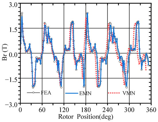
Figure 10 compares the air-gap flux density distributions obtained using the proposed VMN, conventional EMN, and FEA. All three methods reproduce the overall variation trend of the flux density, although certain discrepancies in phase and peak magnitude can be observed. The conventional EMN adopts fixed permeance parameters and does not sufficiently account for the dynamic magnetic-field variations caused by eddy-current reaction. In contrast, the proposed VMN incorporates the frequency-dependent eddy-current reaction into the magnetic network through complex magnetic admittance, thereby describing the phase relationship between the magnetomotive force and magnetic flux. Consequently, the phase deviation between the VMN and FEA results is approximately 2.5 electrical degrees. The remaining discrepancies are mainly attributed to PM element discretization, harmonic truncation, and approximations in the equivalent permeance representation.
Figure 10.
Comparison of air-gap flux-density waveforms.
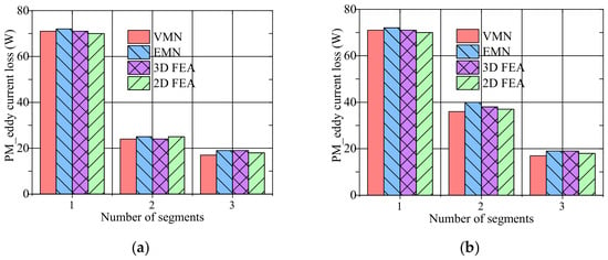
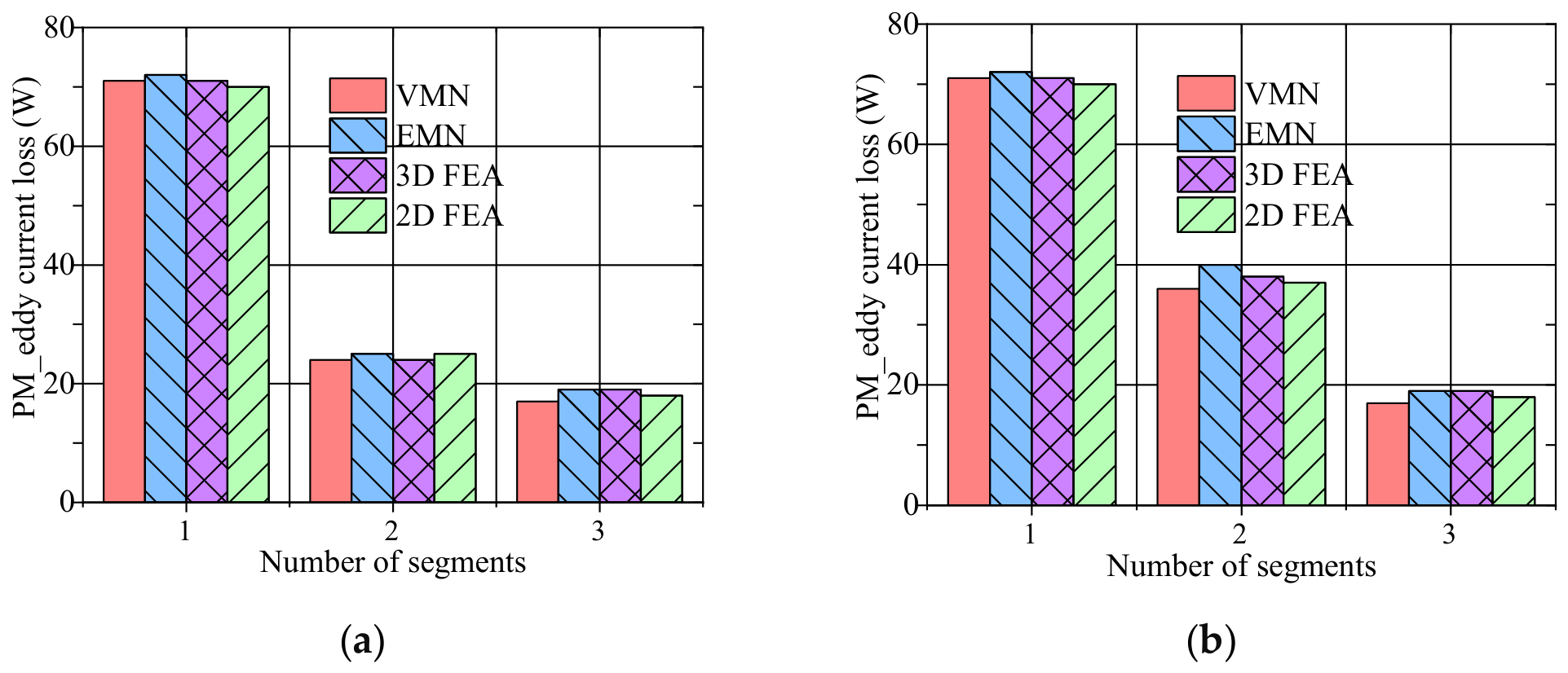
Figure 11 compares PM eddy-current losses for axial and radial segmentation. In both cases, increasing the number of PM segments substantially reduces the loss. For two-segment configurations, axial segmentation produces a greater loss reduction than radial segmentation; the difference becomes smaller for three-segment configurations. The proposed VMN agrees more closely with the 3D FEA results and captures the variation in loss with segmentation. The conventional 2D FEA results do not include axial segmentation or end-region current-return corrections and are therefore retained only as a 2D approximation, not as direct validation of the effect of axial electrical insulation. The 3D FEA results are used as the reference for axial-segmentation losses. The EMN also reproduces the overall trend but shows larger discrepancies, particularly for the two-segment radial configuration.
Figure 11.
PM eddy-current loss: (a) axial segmentation; (b) radial segmentation.
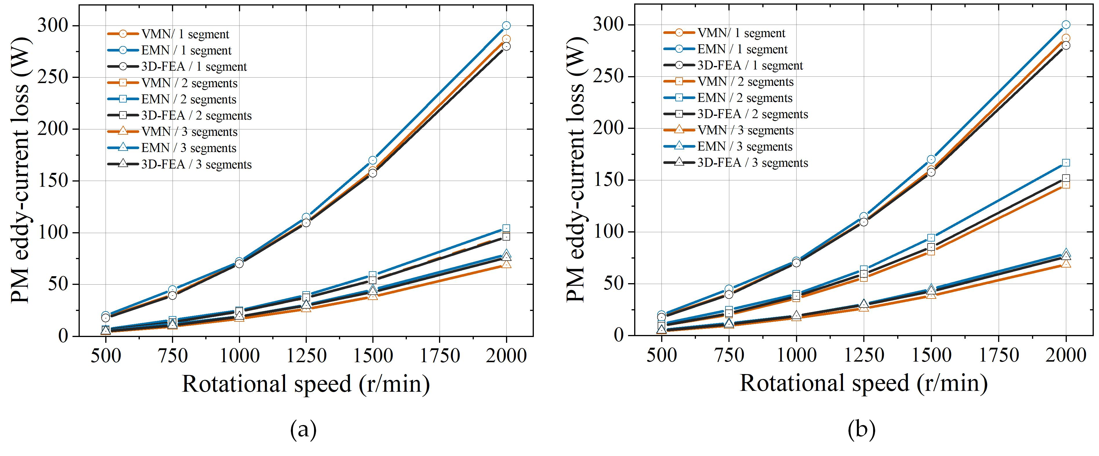
Figure 12 further compares no-load PM eddy-current losses for different speeds and segmentation configurations to assess agreement among the VMN, EMN, and 3D FEA. The speeds are 500, 750, 1000, 1250, 1500, and 2000 r/min, and one-, two-, and three-segment PM configurations are evaluated in both the axial and radial directions. The VMN maintains good prediction accuracy over the investigated speed range. The mean absolute differences from 3D FEA are 1.84 W for axial segmentation and 2.73 W for radial segmentation.
Figure 12.
Comparison of no-load PM eddy-current losses at different speeds: (a) axial segmentation; (b) radial segmentation.
3.2. Experimental Validation and Computational Cost
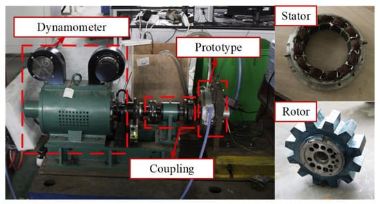
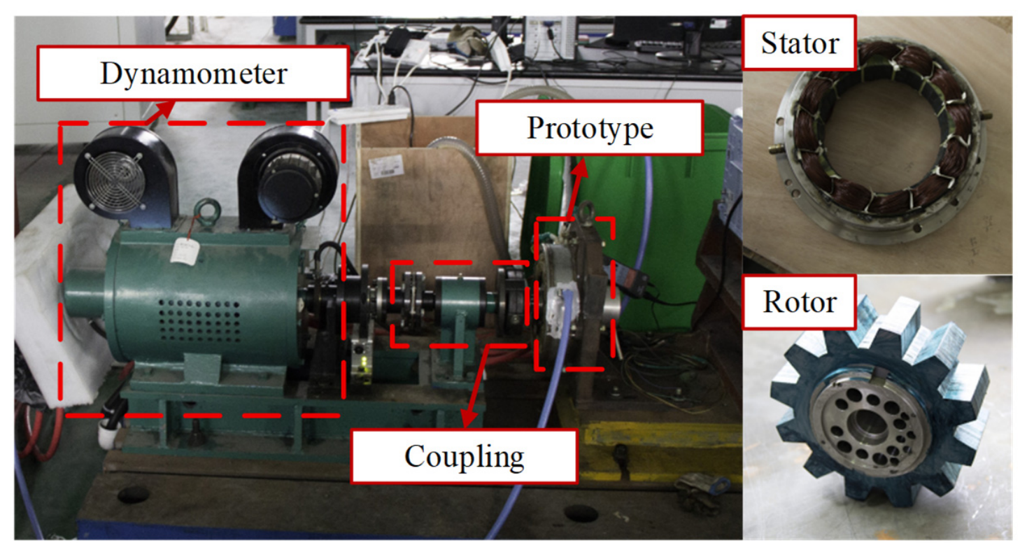
The VMN is further validated using FEA and experimental measurements from a 10 kW prototype. The test platform, which includes a dynamometer, torque sensor, and prototype, is shown in Figure 13.
Figure 13.
Experimental test platform for the 10 kW FSPM machine.
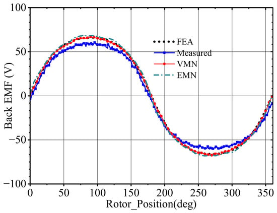
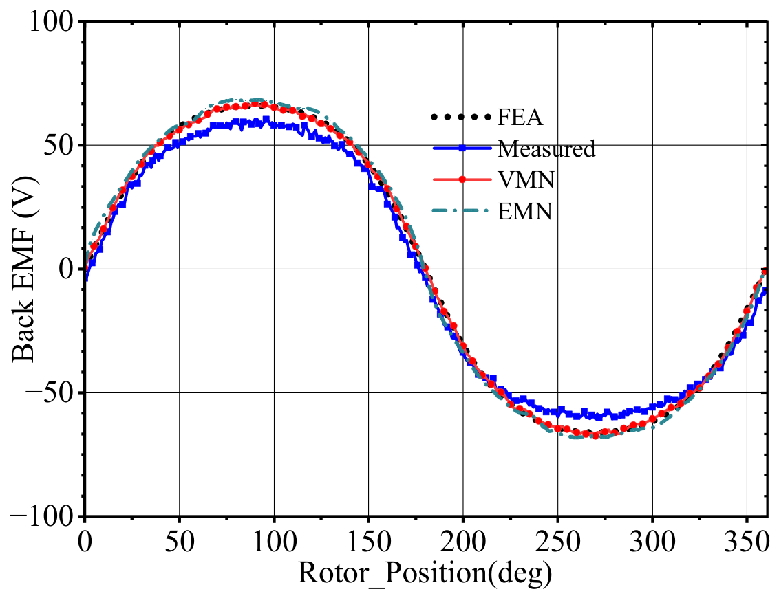
Figure 14 compares the loaded back-EMF waveforms obtained using the VMN, EMN, FEA, and experiment. The VMN peak amplitude is approximately 67 V, compared with approximately 68 V for FEA, corresponding to an estimated amplitude difference of about 1.5%. The measured peak is slightly lower, at approximately 62–63 V, and the estimated amplitude difference between the VMN and measurement is about 6.5–7.0%. The zero-crossing positions of the VMN, FEA, and measured waveforms are broadly similar. The measured waveform has a slightly lower amplitude and greater noise, which may be associated with measurement noise, assembly tolerances, and the simplified coupling permeances in the model.
Figure 14.
Loaded back-EMF waveforms.
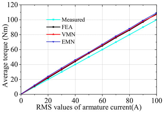
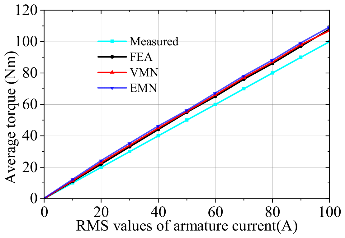
Figure 15 shows that the torque predicted by the VMN nearly coincides with the FEA result over the full current range and captures the trend of the measured torque.
Figure 15.
Torque–current characteristic.
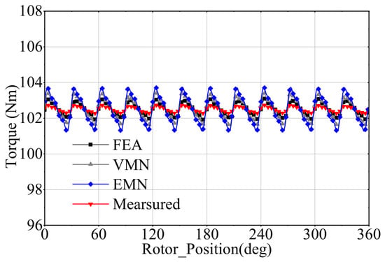
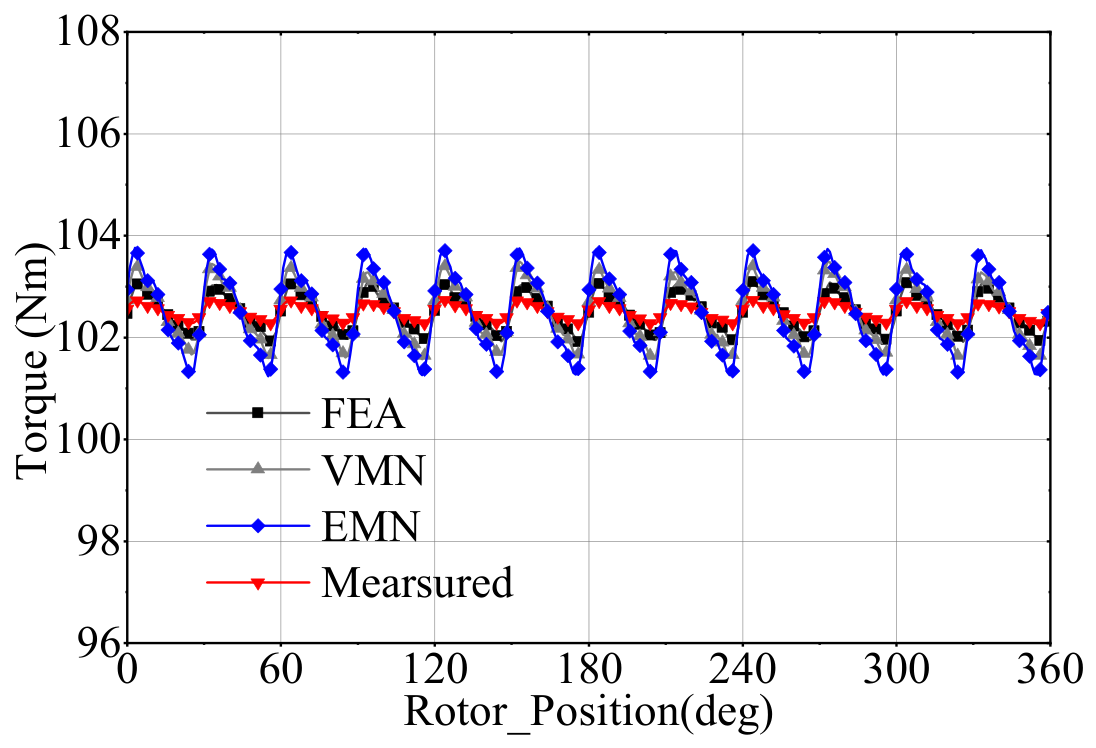
As shown by the load-torque comparison in Figure 16, for the 10 kW FSPM machine, the maximum torque deviations of the VMN relative to measurement and FEA are 1.9% and 2.0%, respectively. Under strongly saturated operating conditions, a fixed-permeance model can produce larger errors, whereas the proposed model maintains the above level of agreement.
Figure 16.
Comparison of load-torque waveforms.
Table 2 summarizes the computational costs. The VMN uses only 2880 nodes, fewer than the EMN, 2D FEA, and 3D FEA models. Under rated load, the CPU time is reduced from 40.3 s for the EMN to 16.2 s for the VMN, while the predictions of saturated flux density and PM eddy-current loss are improved. Compared with FEA, the VMN is approximately 15 times faster than 2D FEA and 280 times faster than 3D FEA under rated load, with substantially lower memory requirements. The simulations were performed on a server equipped with an Intel Xeon 6548Y+ processor and 128 GB of DDR5 memory.
Table 2.
Comparison of computational cost.
4. Discussion
The remaining discrepancies mainly arise from relatively coarse spatial discretization, equivalent leakage permeances, unresolved local end-fringing fields, and mechanical, manufacturing, and measurement effects that are not included in the model. Therefore, high-fidelity FEA remains necessary when detailed local-field distributions or manufacturing effects need to be resolved.
5. Conclusions
This paper proposes a hybrid-dimensional VMN for FSPM machines by integrating rotor-saliency-based air-gap MMF mapping, reluctance–magductance branch modeling, and Schur-complement condensation of a three-dimensional PM subnetwork. The model avoids topology reconstruction as the rotor position changes and incorporates saturation, leakage, and multi-harmonic PM eddy-current reaction in a unified nodal system. Validation on a 12-slot/10-pole, 10 kW prototype shows maximum torque deviations of 1.9% relative to measurement and 2.0% relative to FEA. The VMN uses 2880 nodes and requires 16.2 s under rated load, corresponding to approximately 15 and 280 times the computational speed of the 2D and 3D FEA implementations, respectively. Over the tested 500–2000 r/min speed sweep, the mean absolute PM-loss differences from 3D FEA are 1.84 W for axial segmentation and 2.73 W for radial segmentation. These results demonstrate the proposed framework for PM eddy-current-loss prediction and segmentation assessment in the investigated FSPM machine. Extension to other machine topologies will be investigated in future work.
Supplementary Materials
The following supporting information can be downloaded at: https://www.mdpi.com/article/10.3390/machines14111319/s1, Data S1: Numerical data for the torque–current characteristic; Data S2: Numerical data for the air-gap flux-density waveforms; Data S3: Numerical data for PM eddy-current losses under axial segmentation; Data S4: Numerical data for the back-EMF waveforms; Data S5: Numerical data for PM eddy-current losses under radial segmentation; Data S6: Numerical data for the load-torque waveforms.
Author Contributions
J.W.: conceptualization, methodology, and supervision. X.C.: methodology, software, formal analysis, and writing—original draft preparation. X.Z.: formal analysis and investigation. K.X.: writing—review and editing. Q.Y.: resources. All authors have read and agreed to the published version of the manuscript.
Funding
This research was supported by the National Natural Science Foundation of China (52307064) and the Shanghai Municipal Science and Technology Commission (23YF1428300).
Data Availability Statement
The original simulation and experimental data supporting the findings of this study are provided in the Supplementary Materials.
Conflicts of Interest
The authors declare no conflicts of interest.
Abbreviations
The following abbreviations are used in this manuscript:
| Abbreviation | Definition |
| FSPM | Flux-switching permanent magnet |
| PM | Permanent magnet |
| FEA | Finite-element analysis |
| EMN | Equivalent magnetic network |
| VMN | Vector magnetic network |
| MMF | Magnetomotive force |
| ECL | Eddy-current loss |
| FFT | Fast Fourier transform |
| PWM | Pulse-width modulation |
References
- Chen, H.; El-Refaie, A.M.; Demerdash, N.A.O. Flux-Switching Permanent-Magnet Machines: Opportunities and Challenges—Part II: Design, Control, and Trends. IEEE Trans. Energy Convers. 2020, 35, 699–713. [Google Scholar] [CrossRef] [Scilit]
- Abunike, C.E.; Okoro, O.I.; Far, A.J.; Aphale, S.S. A Review of Optimization Studies on Flux-Switching Machines: Applications and Future Prospects. IEEE Access 2023, 11, 110910–110942. [Google Scholar] [CrossRef] [Scilit]
- Zhang, X.; Zhang, W.; Liang, X.; Lu, P. Performance Analysis and Comparison of Two Flux-Switching Permanent-Magnet Machine Topologies. CES Trans. Electr. Mach. Syst. 2020, 4, 190–197. [Google Scholar] [CrossRef] [Scilit]
- Xiang, Z.; Zhu, X.; Quan, L.; Fan, D. Optimal Design and Analysis of a Hybrid Permanent-Magnet Flux-Switching Machine with a Hybrid Rotor Structure. CES Trans. Electr. Mach. Syst. 2018, 2, 200–206. [Google Scholar] [CrossRef] [Scilit]
- Cheng, X.; Xu, W.; Du, G.; Zeng, G.; Zhu, J. A Novel Low-Eddy-Current-Loss Rotor for High-Speed Permanent-Magnet Machines. CES Trans. Electr. Mach. Syst. 2019, 3, 187–194. [Google Scholar] [CrossRef] [Scilit]
- Sahu, R.; Pellerey, P.; Laskaris, K. An Eddy-Current Loss Model Considering Reaction-Field and Nonuniform Three-Dimensional Magnetic-Field Effects. IEEE Trans. Magn. 2020, 56, 7508404. [Google Scholar] [CrossRef] [Scilit]
- Han, T.; Wang, Y.; Shen, J.X. Analysis and Experimental Method for the Effects of Retaining-Sleeve Structure and Material on Rotor Eddy-Current Losses in High-Speed Permanent-Magnet Machines. IEEE Trans. Ind. Appl. 2020, 56, 4889–4895. [Google Scholar] [CrossRef] [Scilit]
- Li, H.; Zhu, Z.Q.; Hua, H. Comparative Analysis of Flux-Reversal Permanent-Magnet Machines with Toroidal and Concentrated Windings. IEEE Trans. Ind. Electron. 2020, 67, 5278–5290. [Google Scholar] [CrossRef] [Scilit]
- Cao, D.; Zhao, W.; Liu, T.; Wang, Y. A Magneto-Electric Coupling Network Model for Reducing Permanent-Magnet Eddy-Current Losses in Flux-Switching Permanent-Magnet Machines. IEEE Trans. Ind. Electron. 2022, 69, 1189–1199. [Google Scholar] [CrossRef] [Scilit]
- Cheng, M.; Chau, K.T.; Chan, C.C.; Zhou, E.; Huang, X. Nonlinear Variable-Network Magnetic-Circuit Analysis of Doubly Salient Permanent-Magnet Machines. IEEE Trans. Magn. 2000, 36, 339–348. [Google Scholar] [CrossRef]
- Wang, J.; Cheng, M.; Tian, W.; Jiang, Y. Iron-Loss Calculation of PWM-Inverter-Fed FSPM Machines Based on General Air-Gap Magnetic-Field Modulation Theory. IEEE Trans. Ind. Electron. 2022, 69, 12517–12528. [Google Scholar] [CrossRef] [Scilit]
- Cao, D.; Zhao, W.; Ji, J.; Wang, Y. Parametric Equivalent Magnetic Network Modeling for Multiobjective Optimization of Permanent-Magnet Machines. IEEE Trans. Ind. Electron. 2021, 68, 6619–6629. [Google Scholar] [CrossRef] [Scilit]
- Song, Z.; Liu, C.; Chen, Y.; Huang, R. An Air-Gap Permeance and Reluctance-Network Model for Analyzing Vibration-Exciting Forces in In-Wheel Permanent-Magnet Synchronous Machines. IEEE Trans. Veh. Technol. 2022, 71, 7122–7133. [Google Scholar] [CrossRef] [Scilit]
- Ke, H.; Liu, Z.; Chen, Q.; Liu, G.; Xu, G. Analysis of an Auxiliary-Pole Spoke-Type Ferrite Permanent-Magnet Machine Using an Equivalent Magnetic Network with Hybrid Cross-Shaped Mesh Elements. IET Electr. Power Appl. 2023, 17, 474–486. [Google Scholar] [CrossRef] [Scilit]
- Zhao, H.; Chau, K.T.; Yang, T.; Song, Z.; Liu, C. A Novel Quasi-Three-Dimensional Analytical Model for Axial-Flux Machines Considering Magnetic Saturation. IEEE Trans. Energy Convers. 2022, 37, 1358–1368. [Google Scholar] [CrossRef] [Scilit]
- Liu, G.; Wang, Y.; Chen, Q.; Xu, G.; Cao, D. Design and Analysis of a Novel Equivalent Magnetic Network Model for Interior Permanent-Magnet Machines. IEEE Trans. Magn. 2020, 56, 8101112. [Google Scholar] [CrossRef] [Scilit]
- Wang, C.; Liu, Y.; Chen, D.; Zhang, Z. Reducing Permanent-Magnet Eddy-Current Loss in Axial-Flux Permanent-Magnet In-Wheel Machines Using Curved Partial Segmentation. IEEE Trans. Magn. 2023, 59, 93004–93011. [Google Scholar] [CrossRef] [Scilit]
- Li, C.; Wang, X.; Liu, F.; Ren, J.; Xing, Z.; Gu, X. Analysis of a Permanent-Magnet-Assisted Synchronous Reluctance Machine Based on an Equivalent Reluctance-Network Model. CES Trans. Electr. Mach. Syst. 2022, 6, 135–144. [Google Scholar] [CrossRef] [Scilit]
- He, M.; Li, W.; Peng, J.; Yang, J. A Multilayer Quasi-Three-Dimensional Equivalent Model for Axial-Flux Permanent-Magnet Synchronous Machines. CES Trans. Electr. Mach. Syst. 2021, 5, 3–12. [Google Scholar] [CrossRef] [Scilit]
- Cheng, M.; Xu, Z.; Zhang, G. Equivalent Magnetic Network for Flux-Switching Permanent-Magnet Machines Based on Vector Magnetic-Circuit Theory. IEEE Trans. Energy Convers. 2025, 40, 1517–1528. [Google Scholar] [CrossRef] [Scilit]
- Cao, D.; Mecrow, B.C.; Ji, J.; Liu, T. A Hybrid Network Model for Permanent-Magnet Eddy-Current Loss Considering Eddy-Current Reaction Field and PWM Effects in Permanent-Magnet Machines. IEEE Trans. Transp. Electrif. 2025, 11, 3861–3871. [Google Scholar] [CrossRef] [Scilit]
- Zhao, W.; Liu, T.; Ji, J.; Zhu, S.; Cao, D. A Novel Discrete Equivalent Magnetic Network for Electromagnetic-Force and Vibration Calculation in Surface-Mounted Permanent-Magnet Machines Considering Carrier Harmonics. IEEE Trans. Ind. Electron. 2024, 71, 5630–5640. [Google Scholar] [CrossRef] [Scilit]
- Wang, J.; Cao, S.; Qin, W.; Cheng, M.; Yuan, Q.; Xia, K.; Yu, W. PM Eddy Current Loss Calculation Based on Magductance for FSPM Machine. IET Electr. Power Appl. 2025, 19, e70034. [Google Scholar] [CrossRef] [Scilit]
- Hoang, D.-T.; Nguyen, M.-D.; Han, C.; Kim, Y.-J.; Shin, K.-H.; Choi, J.-Y. Analytical Model for Predicting Rotor Eddy Current Loss of PMSMs Considering Magnetic Saturation and Diffusion Effect. IEEE Trans. Energy Convers. 2026, 41, 2383–2396. [Google Scholar] [CrossRef] [Scilit]
- Su, P.; Wang, Y.; Li, Y.; Hua, W.; Shen, Y. Design and Analysis of an Axially Modular Flux-Switching Permanent-Magnet Machine. IEEE Trans. Transp. Electrif. 2023, 9, 3649–3661. [Google Scholar] [CrossRef] [Scilit]
- Zhao, C.; Cheng, M.; Zhou, J.; Ma, Z. A Linear Hybrid Model for Analytical Magnetic-Field Analysis of Flux-Switching Permanent-Magnet Machines. IEEE Trans. Energy Convers. 2023, 38, 1433–1441. [Google Scholar] [CrossRef] [Scilit]
- Wang, J. Iron-Loss Analysis and Modeling of Magnetic-Field-Modulated Permanent-Magnet Machines. Ph.D. Thesis, Southeast University, Nanjing, China, 2022. (In Chinese) [Google Scholar]
- Cheng, M.; Qin, W.; Zhu, X.; Wang, Z. Magductance: Concept, Definition, and Applications. IEEE Trans. Power Electron. 2022, 37, 12406–12414. [Google Scholar] [CrossRef] [Scilit]
- Qin, W.; Cheng, M.; Wang, J.; Zhu, X.; Wang, Z.; Hua, W. Compatibility Analysis among Vector Magnetic-Circuit Theory, Circuit Theory, and Electromagnetic-Field Theory. IEEE Access 2023, 11, 113008–113016. [Google Scholar] [CrossRef] [Scilit]
- Xu, Z.; Cheng, M.; Zhang, G. Vector Magnetic Network Model of a Flux-Switching Permanent-Magnet Hub Motor Based on the Magductance Principle. Trans. China Electrotech. Soc. 2025, 40, 7204–7213. [Google Scholar] [CrossRef]

Disclaimer/Publisher’s Note: The statements, opinions and data contained in all publications are solely those of the individual author(s) and contributor(s) and not of MDPI and/or the editor(s). MDPI and/or the editor(s) disclaim responsibility for any injury to people or property resulting from any ideas, methods, instructions or products referred to in the content. |
© 2026 by the authors. Licensee MDPI, Basel, Switzerland. This article is an open access article distributed under the terms and conditions of the Creative Commons Attribution (CC BY) license.