


Abstract
The performance of linear compressors improves with smeared waveforms compared to symmetrical ones. This paper proposes a novel method using voltage offset to examine its impact on vibration behaviors and performance enhancement. The operating principle of a moving magnet linear compressor is introduced, and a numerical model is established considering the influence of stator assembly. The effect of voltage offset on the vibration behaviors and dynamic performance of the linear compressor is analyzed in both time and frequency domains under six voltage waveforms: the cosine waveform, the cosine waveform without crests, the cosine waveform without troughs, and the cosine waveform without both crests and troughs. Simulation results indicate that at a frequency of 50 Hz, under cosine waveforms, voltage offsets inversely affect the oscillation amplitudes of the piston and stator assemblies. Conversely, under smeared waveforms, oscillation amplitudes increase with forward voltage offsets and decrease with reverse voltage offsets. Additionally, reverse voltage offsets positively impact compressor efficiency and COP. Experimental results confirm the effects of voltage offsets on the performance of the linear compressor.
1. Introduction
Linear compressors are commonly employed in household refrigerators owing to their higher efficiency. The performance of linear compressors is significantly affected by voltage waveforms. A novel method involving voltage offset is proposed in this paper. Investigating the impact of voltage offset on the vibration behaviors and performance of linear compressors is advantageous for the development of the refrigeration industry.
Understanding the principle of linear compressors is crucial for enhancing their performance. Zhang et al. [1] experimentally validated a simulation model for two commercial linear compressors. Bijanzad et al. [2] explored a novel moving magnet linear compressor for household refrigerators, proposing a single-degree-of-freedom model. Chen et al. [3] analyzed a new moving magnet linear compressor design, finding good agreement of motor force between the FEA model and the measurements. Wei et al. [4] developed a dual-piston linear compressor, examining the effects of piston trajectories and operating conditions on its performance. Chen et al. [5] proposed a Co-core Bilateral Reverse Coil and a Halbach permanent magnet ring array structure for a moving coil linear compressor, achieving higher mechanical efficiency than conventional compressors. Li et al. [6] established a real-time measurement bench for a moving coil linear compressor, analyzing the effects of different parameters on efficiency and characteristics. Kong et al. [7] proposed a two-stage moving magnet linear compressor, demonstrating excellent capacity and modulation capabilities. Oh & Lee [8] utilized waste vibrations from the compressor body to create a gap flow, enhancing efficiency through improved heat dissipation. Ding et al. [9] introduced a method to suppress piston offset by discontinuously connecting the compression and back chambers. Zeng et al. [10] proposed vibration isolation methods to address the vibrations of linear compressor. Yang et al. [11] established a vapor-injection system, and the heating performance significantly improved compared to that without injection. Bijanzad et al. [12] analyzed dynamic characteristics of the linear compressor considering the gas and electromagnetic forces, and the results indicate that the efficiency improved at the natural frequency. Hassan et al. [13] provided the design of a moving-magnet linear compressor and evaluated its performance. Li et al. [14] established a real-time measurement system, revealing that the performance of linear compressor was affected by the valve stiffness. Zou et al. [15] proposed an online measurement method of the gas force and examined its impact on the linear compressor performance. Liang [16] developed an oil-free linear compressor, revealing that the piston offset was effectively controlled by a solenoid valve. Chen et al. [17] developed a numerical model of a linear compressor, and the experimental results indicate that the check valve backflow method effectively reduced the piston offset. Bradshaw et al. [18] developed a novel method for predicting the resonance frequency of a linear compressor and explored its performance using a sensitivity analysis. Kim et al. [19] developed a prototype compressor, revealing that its cooling capacity was inherently modulated. Huang et al. [20] built an experimental bench of linear compressor to inhibit the piston offset, noting that there exists an optimal opening of the valve for the best performance. Li et al. [21] established a prototype of a linear compressor, suggesting that the piston diameter significantly affected capacity-modulation performance. Previous research primarily focused on piston dynamics, often overlooking the impact of stator assembly vibrations.
Research has demonstrated the significant impact of voltage waveforms on linear compressor performance. Tan & Dang [22] analyzed the effects of voltage waveforms on efficiency and cooling performance of a Stirling-type pulse tube cryocooler (SPTC). Their experimental results showed that higher efficiencies were achieved with smeared sine or trapezoidal waveforms. Li et al. [23] conducted experiments on a moving coil linear compressor and found that current curves exhibited obvious distortions with various voltage waveforms compared to standard sine wave curves. Qian et al. [24] investigated the effects of driving voltage waveform on an oil-free linear compressor, revealing that single-side clipped sine waves resulted in higher adiabatic efficiency. These findings underscore the substantial influence of voltage waveform on linear compressor performance. Consequently, a novel method involving voltage offsets is proposed to further explore their impacts on performance. This technology adjusts the supply voltage waveform by shifting it up and down, thereby altering waveform values and enhancing compressor efficiency and refrigeration performance.
Addressing the compressor efficiency and performance challenges of smeared waveforms highlighted in previous literature, a novel voltage offset method is introduced to examine its impact on the vibration behavior and performance enhancement of a linear compressor. The operating principle of a moving magnet linear compressor is introduced, and a numerical model is established accounting for the impact of the stator assembly. The influence of voltage offset is analyzed on vibration behavior and performance improvement across both time and frequency domains under various voltage waveforms. Simulation results revealed the optimal voltage offset for performance enhancement across different waveforms. Experimental results confirmed the impact of voltage offset on dynamic characteristics.
2. Linear Compressor
2.1. Operating Principle
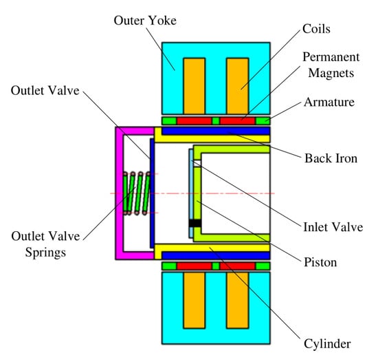
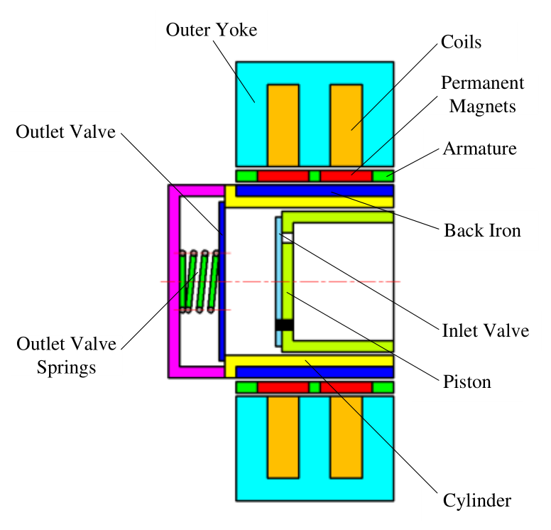
Figure 1 illustrates a schematic of a moving magnet linear compressor, which consists of two main components: the moving assembly and the stator assembly. The moving assembly includes a piston equipped with an inlet valve and an armature containing permanent magnets. The stator assembly comprises a cylinder, outer yokes with coils, and a series of back irons. When alternating current (AC) is applied to the coils, two side legs of the outer yoke are polarized in one direction, while the middle leg is polarized in the opposite direction. A magnetic flux path is created through the outer yoke legs, permanent magnets, and back irons beneath the armature. The resulting magnetic force propels the piston in one direction. When the AC is reversed, the piston moves in the opposite direction.
Figure 1.
Schematic of a moving magnet linear compressor.
The working cycle consists of two main phases: the first half, which includes compression and discharge processes, and the latter half, which involves expansion and suction processes. During compression, the piston moves from the bottom dead center (BDC) to the top dead center (TDC), compressing gas in the chamber and increasing the chamber pressure. The discharge process begins when the piston reaches the pumping start point (PSP), where the chamber pressure matches the discharge pressure, allowing gas to be expelled through the outlet valve. Once the piston arrives at TDC, the minimum clearance volume is achieved. When the AC is reversed, the piston moves in the opposite direction, causing the clearance volume to expand and the chamber pressure to decrease. Once the external pressure surpasses the chamber pressure, gas enters through the inlet valve.
2.2. Numerical Model
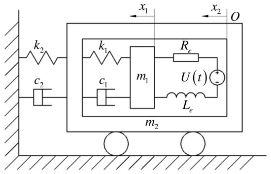
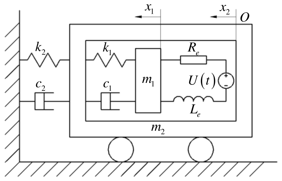
A linear compressor comprises three subsystems: mechanical, electrical, and thermodynamic [25]. Figure 2 presents the numerical model of the linear compressor.
Figure 2.
Numerical model of linear compressor.
The vertex of the cylinder in a static state serves as the coordinate origin. The governing equation for the piston is presented in Equation (1):
The governing equation for the stator assembly is given by Equation (2):
where x1 and x2 denote the positions of the piston and stator assembly, respectively, with their corresponding masses represented by m1 and m2. The total stiffness of the resonance springs is indicated by k1, while the stiffness of the suspension system is represented by k2. The damping coefficient between the piston and the cylinder is denoted by c1, and the damping coefficient of the suspension system is represented by c2. X1 and X2 are initial positions of the piston and stator assembly, respectively. xoffset signifies the piston offset caused by the pressure differential between the compression chamber and its back chamber.
The electromagnetic force is estimated by modeling the solenoid as a perfect circle and disregarding the reluctance of the magnetic flux loop relative to that of the air. Furthermore, the fringing effect at the edges of the solenoid is neglected [12]. The electromagnetic force Fe(t) is described as a product of motor constant and instantaneous current [2], which is expressed by Equation (3):
where Ke represents the motor constant related to the current i(t) flowing through the coils.
Fe(t) = Kei(t)
The magnetic spring force fmag(x) represents the axial force on the piston when no current is applied. The equivalent magnetic spring stiffness kmag is given by Equation (4) [26]:
where S denotes the piston stroke. Considering the vibrations of the piston and stator assemblies, and the piston offset, the equivalent magnetic spring force Fmag(t) is described by Equation (5):
Fmag(t) = kmag(x1 − x2 − (X1 + xoffset − X2))
The gas force Fg(t) is given by Equation (6):
where Ap denotes the piston cross-sectional area, Psuc indicates the suction pressure, Pcyl(t) is the instantaneous pressure in the compression chamber.
Fg(t) = Ap(Pcyl(t) − Psuc)
The dynamic behavior of the valve causes a pressure drop, while gas leakage contributes to power loss [14]. Assuming the fluid behaves as an ideal gas, and disregarding valve dynamics and the gas leakage, the process is considered isentropic. Under these conditions, the instantaneous pressure Pcyl(t) is presented in Equation (7).
where Pdis represents the discharge pressure, X1′ denotes the piston oscillation amplitude, ω signifies the driving angular frequency, n is the heat capacity ratio.
The high-order nonlinear gas force is linearized using the describing function method [27]. Both LV [26] and XIE [28] have validated that the equivalent model derived from this method accurately reflects the actual performance of the linear compressor system. The gas force is expressed by Equation (8) using the describing function method.
where u1 and u2 represent the oscillatory functions of the piston and stator assemblies, respectively. Fs is the static component of gas force, and heq denotes the equivalent damping coefficient of the gas force, as represented by Equation (9).
where heq′ is defined by Equation (10).
where X2′ is the stator assembly oscillation amplitude. keq indicates the equivalent stiffness of the gas force, which is given by Equation (11).
The governing equation for the electrical subsystem is given by Equation (12).
where Le represents the equivalent inductance, Re denotes the equivalent resistance, U(t) is the supply voltage.
The piston position x1 is expressed as follows:
x1 = X1 + xoffset + u1
The stator assembly position x2 is represented as follows:
x2 = X2 + u2
The equivalent dynamic model of the linear compressor is reformulated in Equation (13).
The equivalent model is transformed into matrix form, as shown in Equation (14)
where the independent variable vector U is presented as follows:
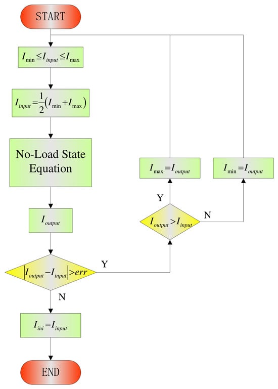
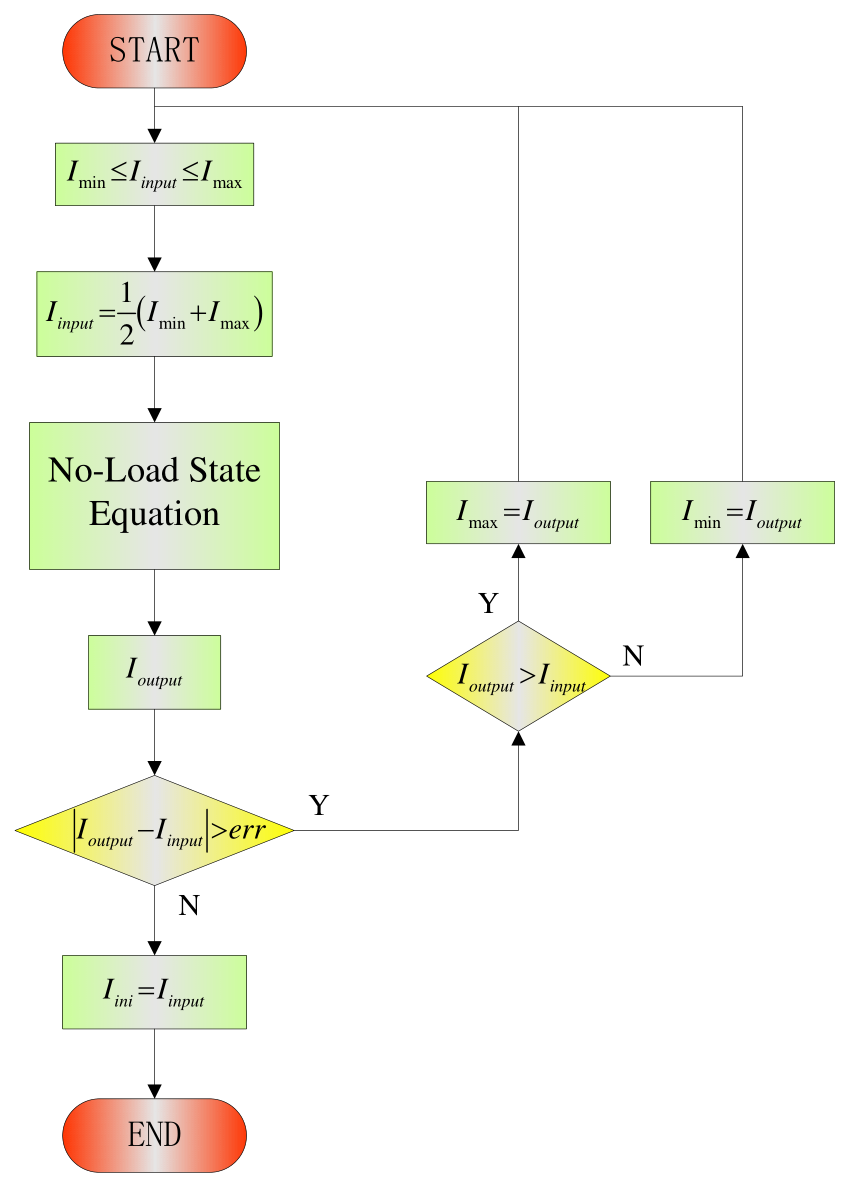
Figure 3 exhibits the flowchart for the initial current iteration, which employs the bisection method. The input current is derived from specific minimum and maximum values. The fourth-order Runge–Kutta method iterates the no-load equation, modeled without gas force, to determine the output value. If the difference between the output and the median is less than the error margin, the median is set as the initial current. If the difference exceeds the error, the maximum or minimum values are adjusted, and the iteration continues until the desired accuracy is achieved. The bisection method ensures the initial current accuracy of 10−2 A.
Figure 3.
Flowchart for initial current iteration.
The equivalent model of the linear compressor is solved using the fourth-order Runge–Kutta method [29]. The initial conditions are as follows:
where xclear denotes the piston clearance for the initial position.
The compressor efficiency is represented by Equation (15).
where ηmotor and ηmech are motor and mechanical efficiencies of the linear compressor, respectively, as shown in Equations (16) and (17) [4,26]:
where Irms denotes the root-mean-square current, Pin is the input power.
ηcom = ηmotor × ηmech
The cooling capacity of the linear compressor is described by Equation (18):
where signifies the mass flow rate of the linear compressor, h1 represents the enthalpy for the suction conditions, h3 is the inlet enthalpy of evaporator.
The COP of the linear compressor can be described as follows:
3. Experimental Setup
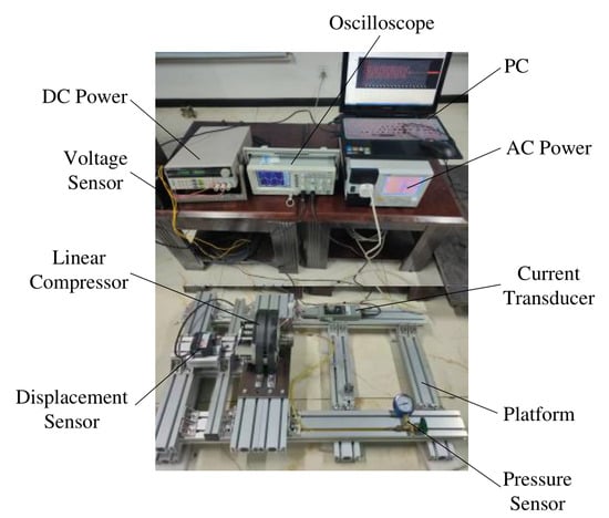
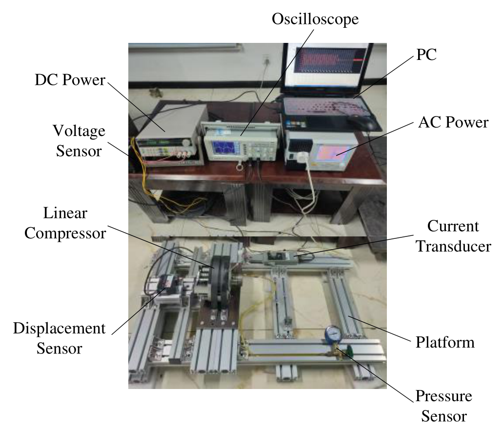
Figure 4 illustrates the test rig setup for the linear compressor. The compressor was secured to a platform. The piston movement was measured by a displacement sensor, with data stored on a PC. A DC power source was used to ensure the stable operation of the displacement sensor. A pressure sensor was used to measure the discharge pressure. When AC power was supplied with varying frequencies and waveforms, the real-time current was measured by a current transducer, and this dynamic data was also recorded on the PC. Table 1 details the instruments used in the test rig.
Figure 4.
Test rig for linear compressor.
Table 1.
Instruments for test rig.
The fundamental equations for uncertainty analysis are presented in Equations (20) and (21), derived from the specifications and uncertainties of the experimental test rig [30].
where R denotes the function of experimental measurement Xei, and each term represents the contribution of uncertainty from an individual variable δXei to the overall uncertainty of the result δR.
R = R(Xe1,Xe2,Xe3,…Xen)
4. Results and Discussions
The performance of linear compressors improves when driven by non-standard voltage waveforms compared to standard sine waveforms [24]. In this paper, the influence of voltage offset is investigated on the nonlinear vibration behaviors and dynamic performance of a linear compressor under various voltage waveforms. The voltage waveform types are listed in Table 2, and the corresponding voltage curves are shown in Supplementary Materials.
Table 2.
Voltage waveform types.
The parameters used for the simulation of linear compressor are listed in Table 3.
Table 3.
Parameters for simulation of linear compressor.
4.1. Cosine Waveform
The effects of voltage offset are analyzed on the performance of linear compressors in both time and frequency domains under cosine waveforms. The voltage offset ratio is defined as the ratio of voltage offset to rated voltage. A negative ratio indicates reverse voltage offsets, while a positive ratio signifies forward voltage offsets. To facilitate comparisons of the impacts of voltage offset, the reductions in voltage amplitude are set to equal to voltage offsets.
4.1.1. Dynamic Characteristics in Time Domain
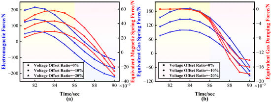
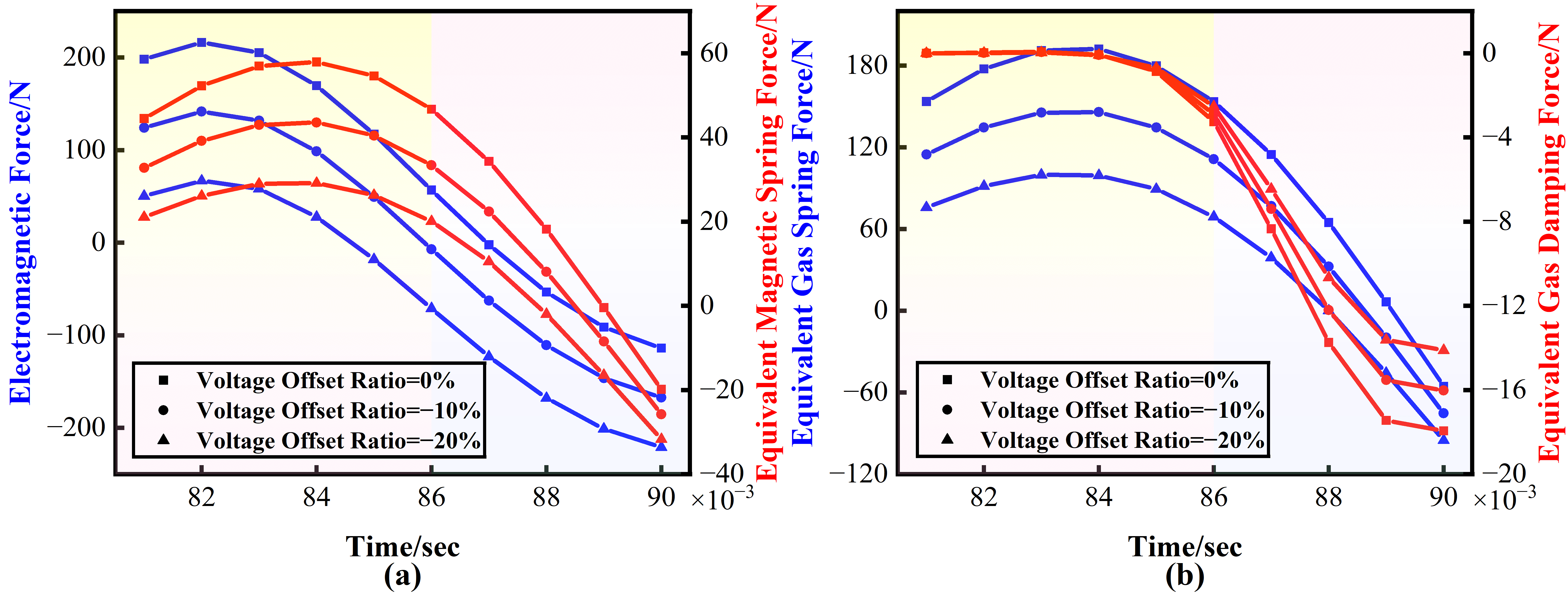
Figure 5 illustrates the force responses during the first half cycle with for waveforms 1 at 50 Hz. Initially, gas enters the chamber through the inlet valve, requiring the linear compressor to expend significant energy to compress it. This process causes the electromagnetic force to gradually increase. As the piston moves, the clearance volume decreases, compressing the gas and increasing the equivalent gas spring force. Simultaneously, the magnetic spring force rises due to its positive relationship with the displacement difference between the piston and stator assemblies, as shown in Equation (5). The electromagnetic force reduces due to increasing magnetic spring force, leading to the reduction in equivalent gas spring force. Additionally, as gas enters the compressor chamber, the equivalent gas damping force gradually increases. During the discharge process, gas exits through the outlet valve, causing the equivalent gas spring and damping forces to decrease, which in turn reduces the electromagnetic force. When reverse voltage offsets increase, the supply voltage decreases, leading to a reduction in electromagnetic force and a subsequent decrease in thrusting force. This reduction in thrusting force results in a decrease in the equivalent gas force.
Figure 5.
Force responses with reverse voltage offsets at 50 Hz. (a) Electromagnetic force. (b) Equivalent gas force.
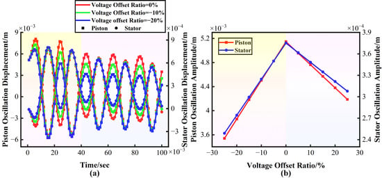
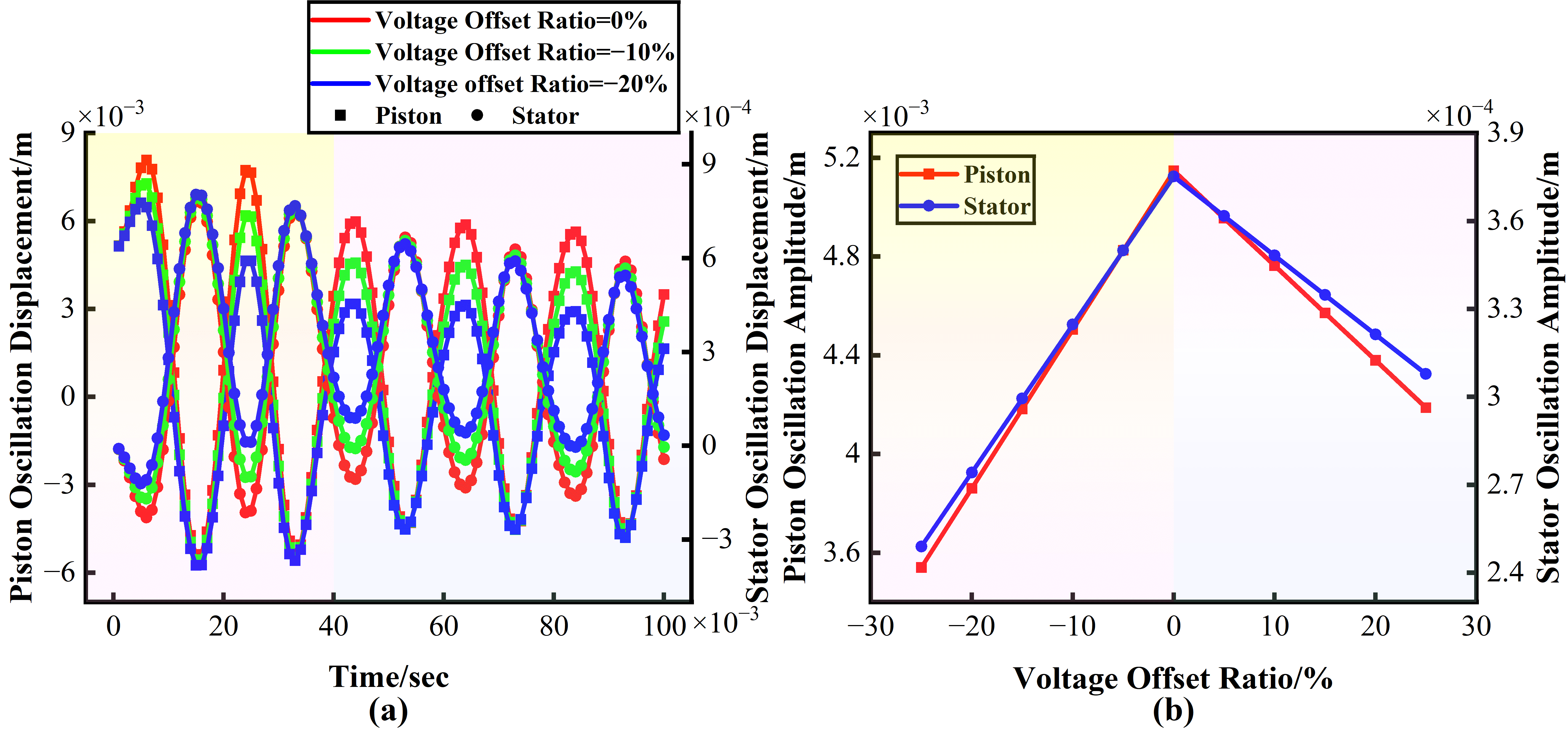
Figure 6 presents the motion responses of the piston and stator assemblies at 50 Hz with varying voltage offsets. The piston moves relative to the stator assembly. During the unstable stage (the first two cycles), both oscillation displacements show decreasing amplitude patterns, with vibration intensity diminishing as reverse voltage offsets increase. In the stable stage (from the third cycle onward), which exhibits the stable system performance, the piston oscillation displacements follow quasi-sinusoidal trends, while the stator assembly displays decreasing amplitude trends. This behavior likely results from continuous electromagnetic forces on the piston, whereas the stator assembly experiences gas friction forces without additional power input. The oscillation amplitudes of both the piston and stator assemblies decrease with larger voltage offsets, possibly due to the combined force in the chamber.
Figure 6.
Responses of oscillation displacement with reverse voltage offsets at 50 Hz. (a) Oscillation displacements of the piston and stator assemblies with time. (b) Oscillation amplitudes of the piston and stator assemblies across various voltage offsets.
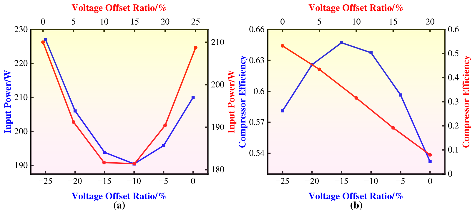
Figure 7 presents the power performance at 50 Hz with varying voltage offsets. The lowest input power is required at a 10% voltage offset ratio for both waveform types. For the cosine waveform with reverse voltage offsets, the minimum input power is approximately 190.4 W, a 9.3% reduction from the 210 W required without voltage offsets. In contrast, with forward voltage offsets, the minimum input power is 181.4 W, a 13.6% reduction. Maximum compressor efficiency occurs at a 15% reverse voltage offset ratio, affected by input power and copper loss. However, the compressor efficiency decreases with increasing forward voltage offsets due to rising copper loss. Without voltage offsets, compressor efficiency is about 0.53, while it peaks at 0.65 with a 15% reverse voltage offset ratio, marking a 23% increase.
Figure 7.
Power performance to various voltage offsets at 50 Hz. (a) Input power. (b) Compressor efficiency.
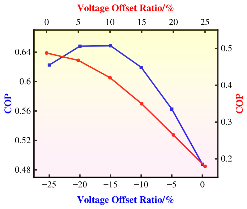
Figure 8 exhibits the COP across various voltage offsets at 50 Hz. The maximum COP is achieved at a 15% reverse voltage offset ratio, influenced by input power and cooling capacity. In contrast, as forward voltage offsets increase, the COP decreases.
Figure 8.
COP across various voltage offsets at 50 Hz.
4.1.2. Dynamic Characteristics in Frequency Domain
The performance of linear compressors is mainly determined by its driving frequency.
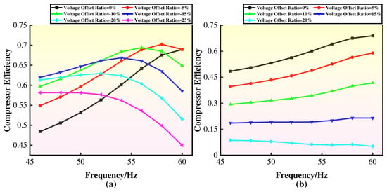
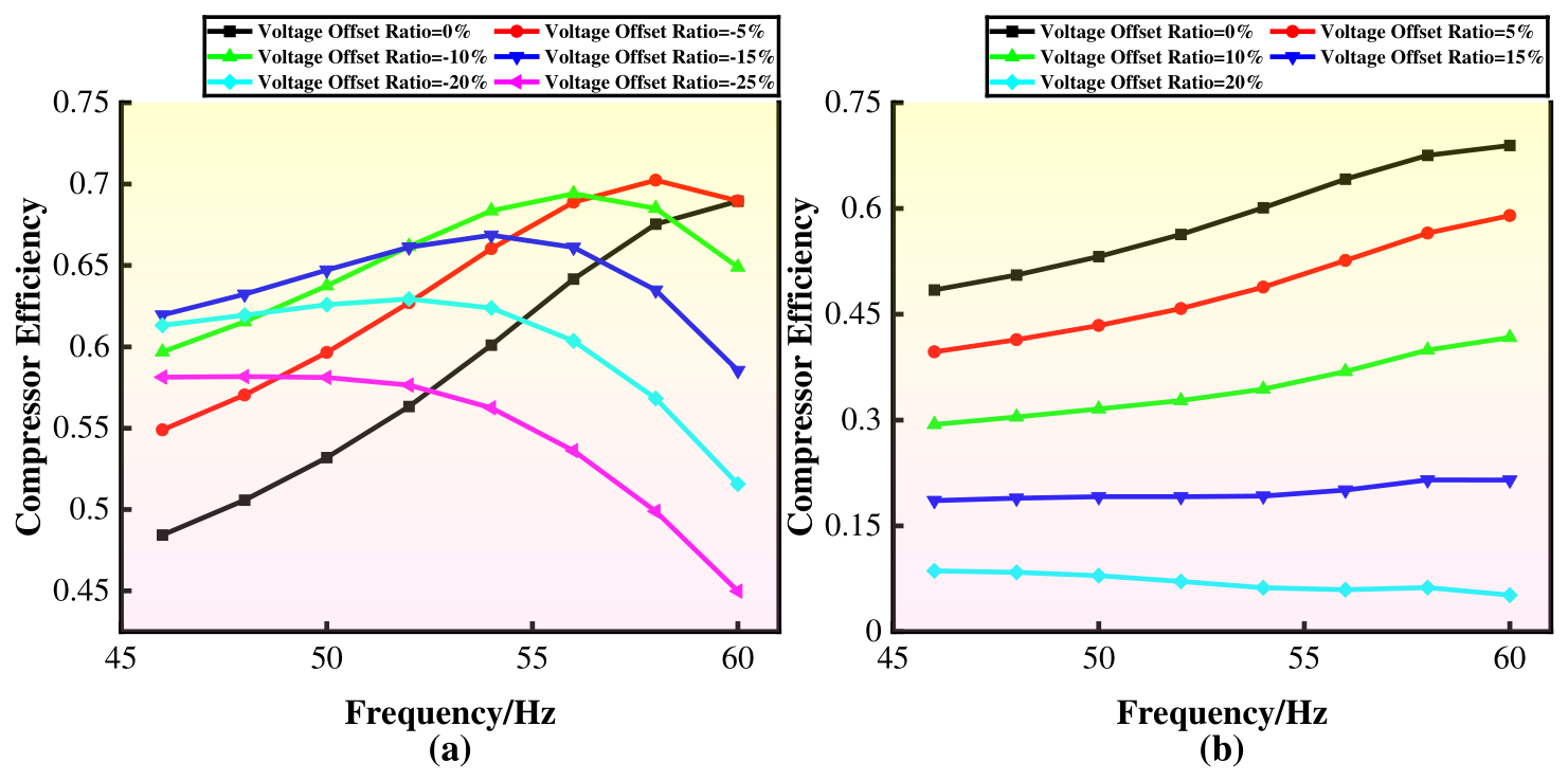
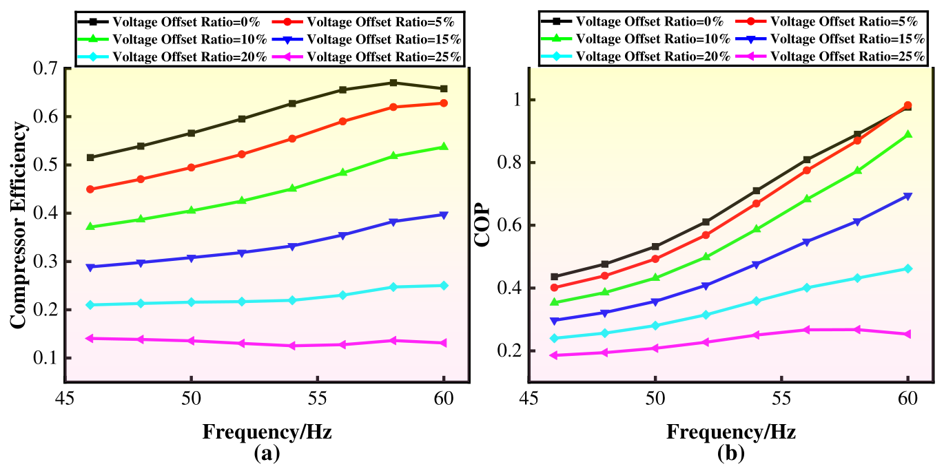
Figure 9 illustrates the compressor efficiency at different frequency. For the cosine waveform with reverse voltage offsets, the highest compressor efficiency occurs at a 5% reverse voltage offset ratio at 58 Hz. In contrast, the compressor efficiency reaches its peak without voltage offsets for the cosine waveform with forward voltage offsets.
Figure 9.
Compressor efficiency at different frequency. (a) Compressor efficiency with reverse voltage offsets. (b) Compressor efficiency with forward voltage offsets.
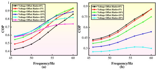
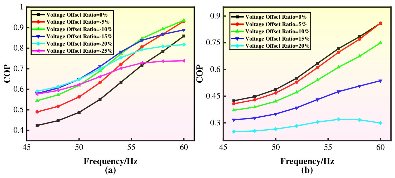
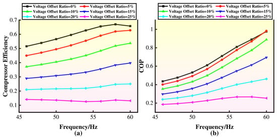
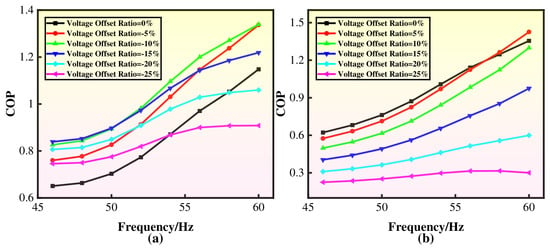
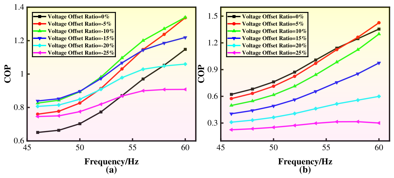
Figure 10 presents the COP at different frequency. As frequency rises, the COP improves. For the cosine waveform with reverse voltage offsets, the COP peaks at a 10% voltage offset ratio, due to minimal input power. Conversely, with forward voltage offsets, the highest COP occurs at a 5% voltage offset ratio.
Figure 10.
COP at different frequency. (a) Reverse voltage offsets. (b) Forward voltage offsets.
4.2. Cosine Waveform Without Crests
The impact of voltage offset is analyzed on the performance of linear compressors in both time and frequency domains under cosine waveforms without crests. In this paper, a cosine waveform without crests is defined as having a crest height that is 70% of the standard cosine crest height.
4.2.1. Dynamic Characteristics in Time Domain
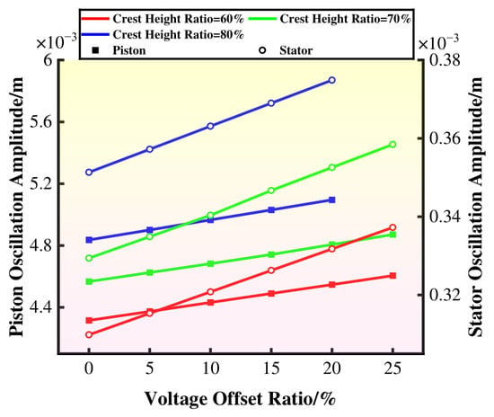
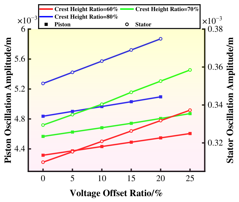
Figure 11 depicts the responses of oscillation amplitudes of the piston and stator assemblies at 50 Hz. As voltage offsets increase, the oscillation amplitudes rise. Additionally, at different crest heights, these oscillation characteristics also increase, given a specific voltage offset. This behavior occurs because higher supply voltages, resulting from larger crest heights, provide more energy.
Figure 11.
Responses of oscillation amplitudes with forward voltage offsets at 50 Hz.
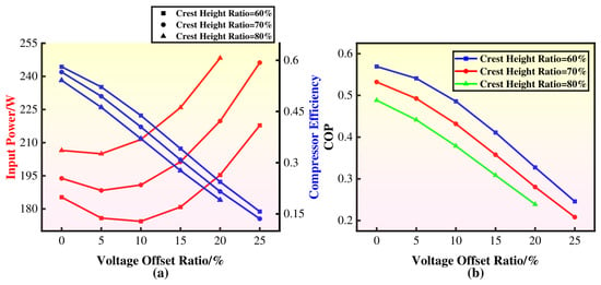
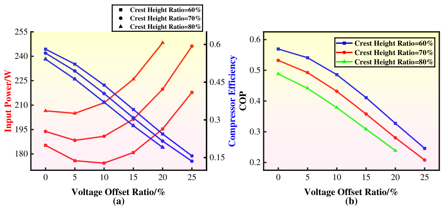
Figure 12 illustrates the power performance with voltage offsets at 50 Hz. As voltage offsets increase, compressor efficiency decreases due to rising copper loss. The least input power is required at a 5% voltage offset ratio. When crest heights increase, the input power rises due to higher voltage supply. The COP decreases with increasing voltage offsets, because of higher input power and reduced cooling capacity. At a specific voltage offset, the COP increases with smaller crest heights, owing to the reduction in input power.
Figure 12.
Power performance with forward voltage offsets at 50 Hz. (a) Input power and compressor efficiency. (b) COP.
4.2.2. Dynamic Characteristics in Frequency Domain
Figure 13 presents the power performance of the linear compressor with forward voltage offsets at different frequencies. The compressor efficiency peaks at 58 Hz without voltage offsets, due to the motor output power and the friction force between the piston and stator assemblies. As frequency increases, the COP also increases, peaking with a 5% voltage offset ratio. This peak results from the optimal balance between input power and cooling capacity.
Figure 13.
Power performance with forward voltage offsets at different frequencies. (a) Compressor efficiency. (b) COP.
4.3. Cosine Waveform Without Troughs
The impact of voltage offset is analyzed on the performance of linear compressors in both time and frequency domains under cosine waveforms without troughs. In this paper, the cosine waveform features a trough height that is 70% of the standard cosine trough height.
4.3.1. Dynamic Characteristics in Time Domain
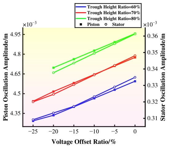
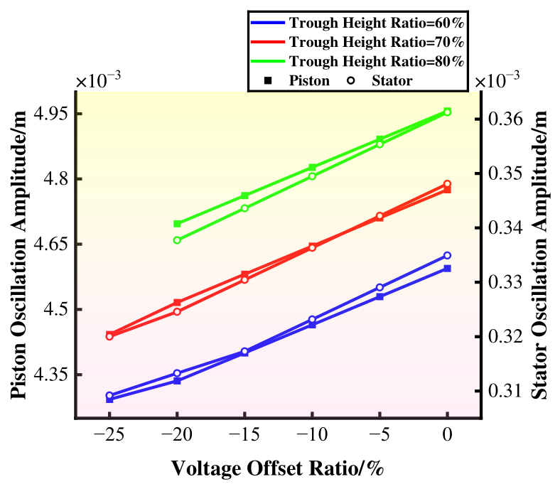
Figure 14 illustrates the responses of oscillation amplitudes of the piston and stator assemblies with reverse voltage offsets at 50 Hz. As voltage offsets increase, the oscillation amplitudes decrease due to the combined force. Conversely, when the trough heights increase, the oscillation amplitudes rise, attributed to the higher supply voltage.
Figure 14.
Responses of oscillation amplitudes with reverse voltage offsets at 50 Hz.
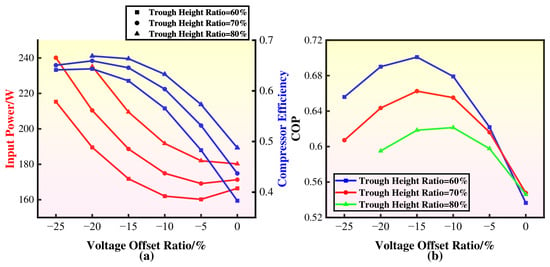
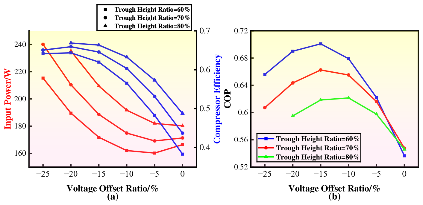
Figure 15 exhibits the power performance of the linear compressor with reverse voltage offsets at 50 Hz. The minimum input power occurs at voltage offset ratios of 5%. However, the compressor efficiency peaks at a voltage offset ratio of 20%. This suggests that compressor efficiency improves with appropriate voltage offsets. Conversely, as the trough heights increase, the input power and compressor efficiency also increase. This indicates that further performance enhancement is achieved by adjusting trough heights. The highest COP occurs at a 15% voltage offset ratio. As trough heights increase, COP decreases because of more input power.
Figure 15.
Power performance with reverse voltage offsets at 50 Hz. (a) Input power and Compressor efficiency. (b) COP.
4.3.2. Dynamic Characteristics in Frequency Domain
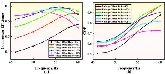
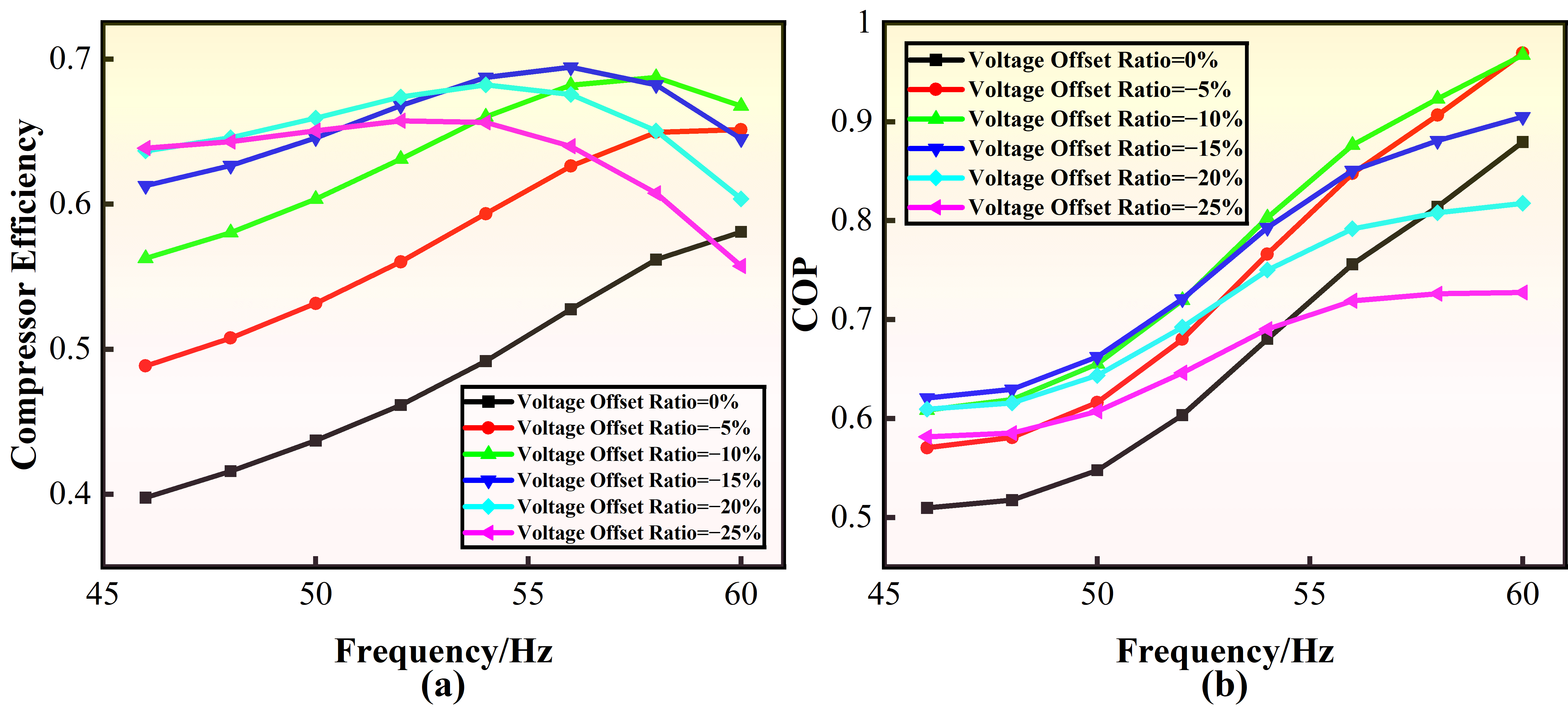
Figure 16 presents the power performance with reverse voltage offsets at different frequencies. Compressor efficiency peaks at a 15% voltage offset ratio at 56 Hz. The highest COP is observed with a 5% voltage offset ratio at 60 Hz, influenced by both cooling capacity and input power.
Figure 16.
Power performance with reverse voltage offsets at different frequencies. (a) Compressor efficiency. (b) COP.
4.4. Cosine Waveform Without Crests and Troughs
The effects of voltage offset are analyzed on the performance of linear compressors in both time and frequency domains under cosine waveforms without crests and troughs. These waveforms are categorized into two types, as detailed in Table 4.
Table 4.
Voltage waveforms without crests and troughs.
4.4.1. Dynamic Characteristics in Time Domain
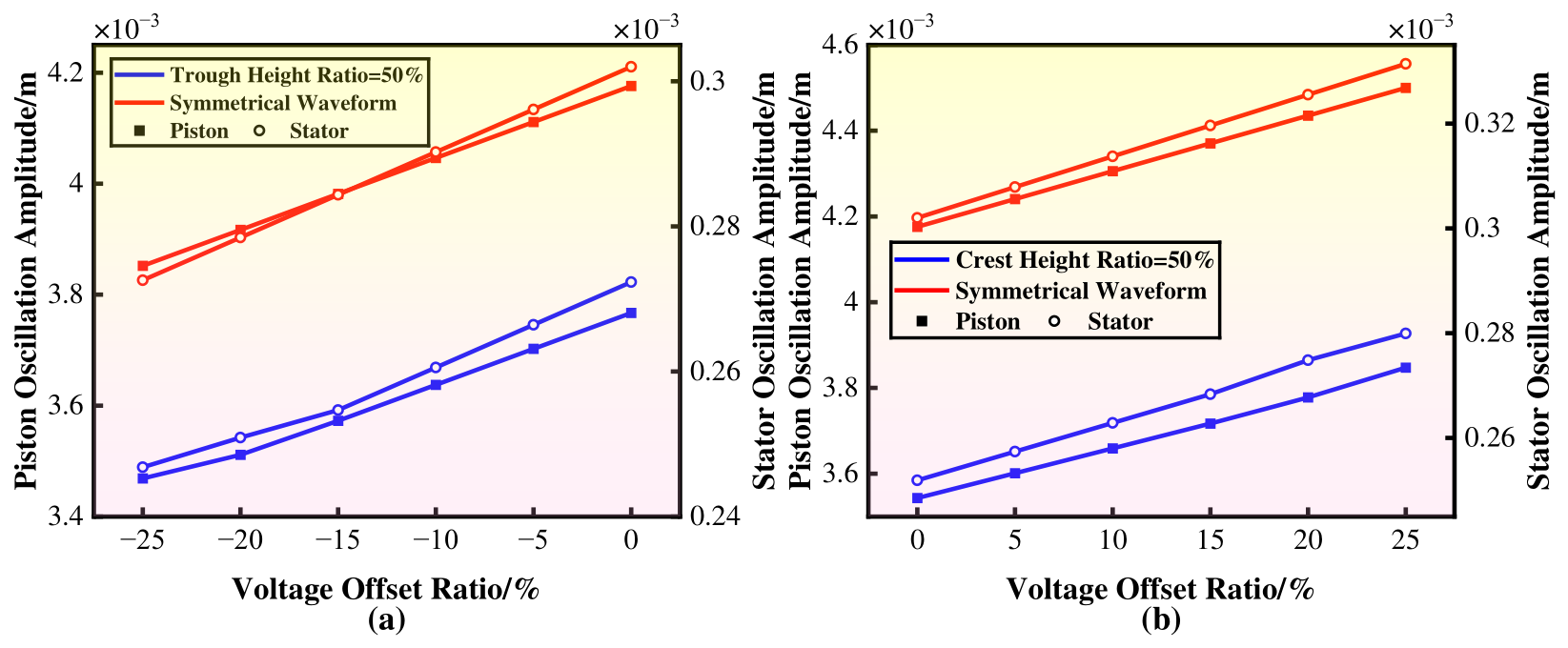
Figure 17 illustrates the oscillation amplitudes of the piston and stator assemblies with voltage offsets at 50 Hz. With increased reverse voltage offsets, their oscillation amplitudes decrease, owing to the combined force. Conversely, with forward voltage offsets, increasing voltage offsets lead to higher oscillation amplitudes. Compared to a symmetrical waveform with crest and trough height ratios of 70%, the parameters of symmetrical waveforms are significantly larger than those of asymmetrical ones. This difference results from the greater electromagnetic force generated by higher supply voltage.
Figure 17.
Responses of oscillation amplitudes with voltage offsets at 50 Hz. (a) Reverse voltage offsets. (b) Forward voltage offsets.
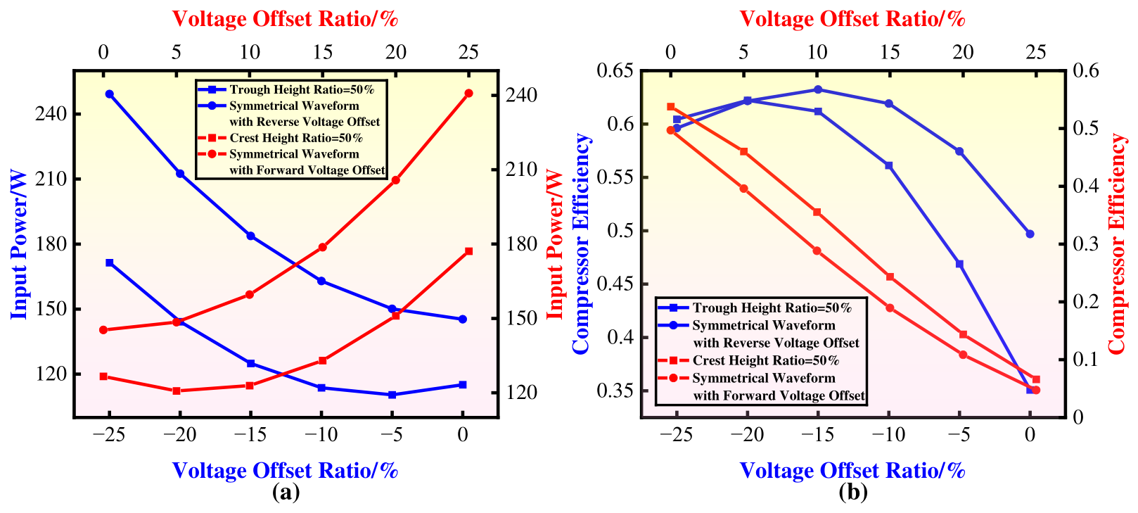
Figure 18 shows the power performance with voltage offsets at 50 Hz. The lowest input power for both waveform types is required at a 5% voltage offset ratio, indicating that input power is minimized by adjusting the voltage offset appropriately. Compared to symmetrical waveforms, where both crest and trough height ratios are 70%, the input power for symmetrical waveforms is significantly higher than that for asymmetrical waveforms. This is due to the larger energy supplied by a higher voltage supply. For the cosine waveform with reverse voltage offsets, the peak compressor efficiency is achieved at a 20% voltage offset ratio. Maximum compressor efficiency reaches 0.62, a 77% improvement over the compressor efficiency of 0.35 without voltage offsets. In contrast, for the symmetrical waveform, the maximum compressor efficiency is 0.63 at a 15% voltage offset ratio, a 26% improvement compared to that without voltage offsets. This demonstrates that the increase in compressor efficiency is more pronounced with asymmetrical waveforms than with symmetrical ones. Conversely, with forward voltage offsets, increasing voltage offsets reduces compressor efficiency.
Figure 18.
Power performance with voltage offsets at 50 Hz. (a) Input power. (b) Compressor efficiency.
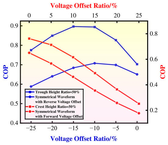
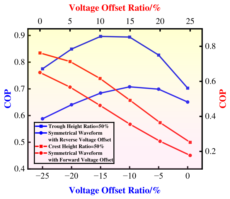
Figure 19 illustrates the COP of the linear compressor at various voltage offsets for two waveform types at 50 Hz. With reverse voltage offsets, the COP peaks at a 15% voltage offset ratio. Conversely, with forward voltage offsets, the COP decreases as the voltage offsets increase. When comparing the COP of asymmetrical and symmetrical waveforms, the asymmetrical waveform exhibits a significantly higher COP. This suggests that applying voltage offsets to asymmetrical waveforms is more beneficial for enhancing COP.
Figure 19.
COP across various voltage offsets at 50 Hz.
4.4.2. Dynamic Characteristics in Frequency Domain
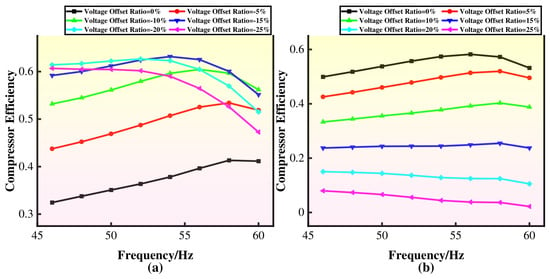
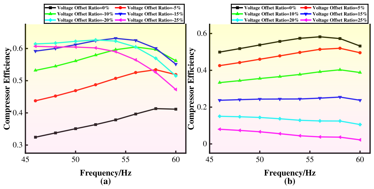
Figure 20 presents the compressor efficiency of the linear compressor across various voltage offsets in the frequency domain. For the cosine waveform with reverse voltage offsets, the compressor efficiency peaks at a voltage offset ratio of 15% around 54 Hz. Compared to the efficiency without voltage offsets, compressor efficiencies with voltage offsets are significantly higher, indicating that proper adjustment of reverse voltage offset and frequency greatly improves compressor efficiency. In contrast, for the cosine waveform with forward voltage offsets, the compressor efficiency peaks without voltage offsets.
Figure 20.
Compressor efficiency with voltage offsets at different frequencies. (a) Reverse voltage offsets. (b) Forward voltage offsets.
Figure 21 illustrates the COP at different frequencies for two waveform types. For the cosine waveform with reverse voltage offsets, the COP peaks at a 10% voltage offset ratio. Compared to the maximum COP of 1.148 without voltage offsets, a 10% voltage offset ratio boosts COP to an estimated 1.339, marking a 17% improvement. In contrast, with forward voltage offsets, the maximum COP of 1.426 is achieved at a 5% voltage offset ratio, a 5% enhancement over the peak value of 1.355 without voltage offsets.
Figure 21.
COP with voltage offsets at different frequencies. (a) Reverse voltage offsets. (b) Forward voltage offsets.
4.5. Performance Cross-Comparison
Table 5 compares compressor efficiency and COP across various waveforms at 50 Hz. The highest compressor efficiency occurs at a 20% voltage offset ratio under the cosine waveform without troughs. Conversely, the COP peaks at a reverse voltage offset ratio of 15% under the cosine waveform without crests and troughs. Furthermore, the maximum compressor efficiency and COP are achieved with reverse voltage offsets. In contrast, with forward voltage offsets, these parameters peak without voltage offsets. These findings suggest that reverse voltage offsets positively influence compressor efficiency and COP.
Table 5.
Cross-comparison of performance at 50 Hz among different waveforms.
Table 6 presents a comparison of compressor efficiency and COP across various frequencies and waveforms. The highest compressor efficiency is achieved at 58 Hz with a 5% reverse voltage offset ratio under the cosine waveform. Conversely, the COP peaks with a 5% forward voltage offset ratio under the cosine waveform without crests and troughs at 60 Hz. Notably, the maximum COP is observed at 60 Hz for all six waveform types, suggesting that COP increases with frequency.
Table 6.
Cross-comparison of performance across various frequencies among different waveforms.
4.6. Experimental Validations
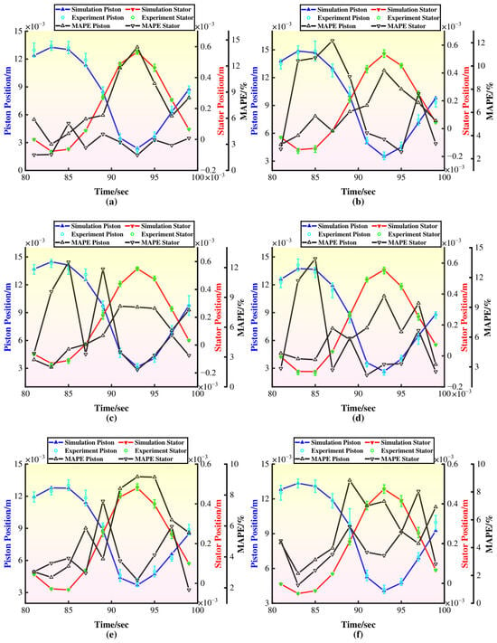
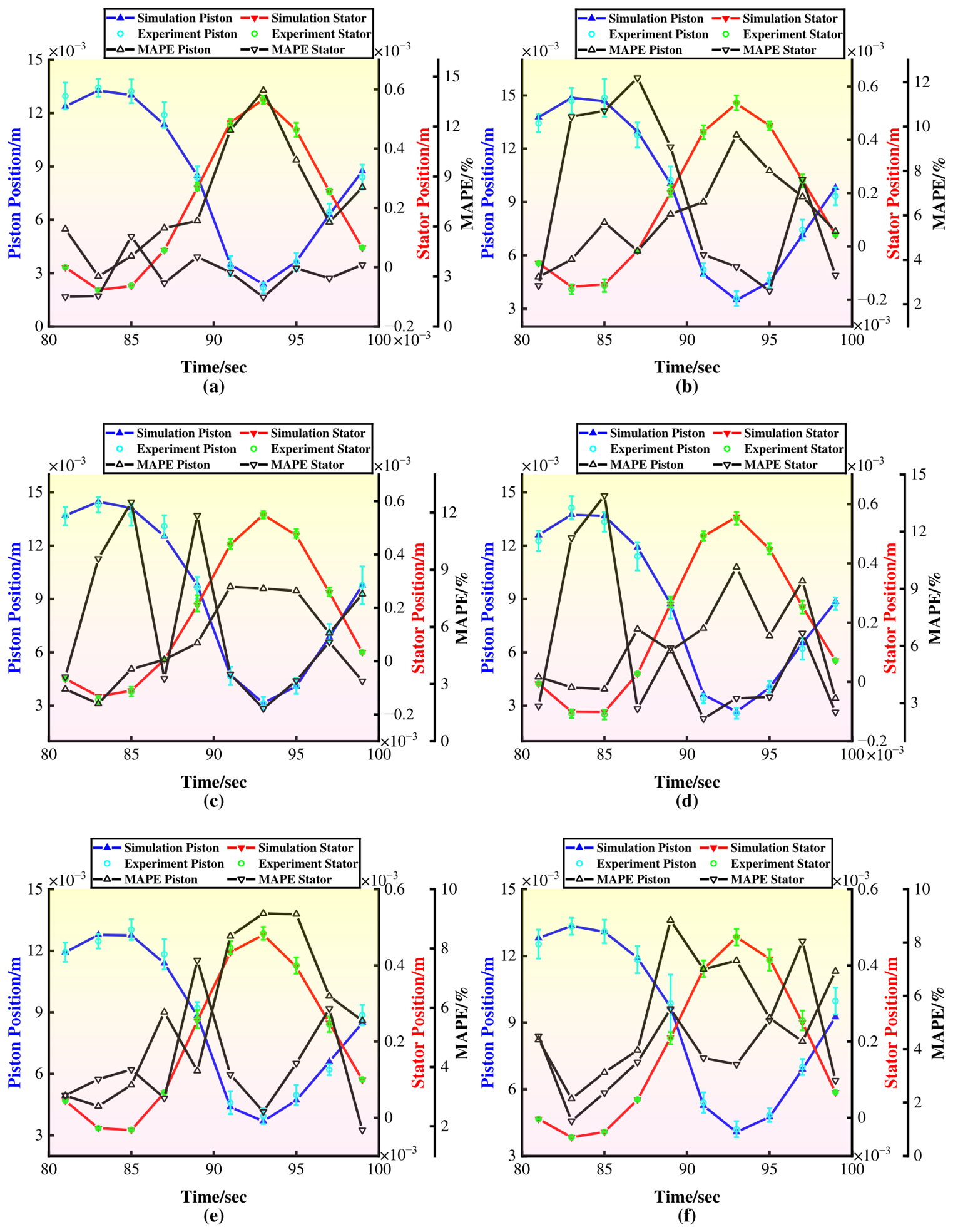
To validate the effects of voltage offset on the performance of linear compressors, experiments were conducted under these voltage waveforms. Each test was repeated three times, and the average values, error bars, and Mean Absolute Percentage Error (MAPE) of the positions of the piston and stator assemblies were calculated at 50 Hz, as shown in Figure 22. The figures in the Supplementary Materials compare simulations and experiments, detailing the amplitudes of the piston and stator assemblies over voltage offsets and frequencies. The simulations assumed the fluid behaved as an ideal gas, excluding the effects of valve vibrations and gas leakage. The MAPE for these parameters remains within an acceptable range of 15%.
Figure 22.
Comparison of the positions of the piston and stator assemblies between simulations and experiments at 50 Hz. (a) Waveform 1. (b) Waveform 2. (c) Waveform 3. (d) Waveform 4. (e) Waveform 5. (f) Waveform 6.
5. Conclusions
This paper presented the voltage offset method applied to different waveforms and investigated its effects on the vibration behavior and performance of linear compressors. Reverse voltage offsets positively affect compressor efficiency and COP. Although this study used a specific linear compressor and operating environment, the proposed mathematical model is modular. For other linear compressors with similar geometries and boundary conditions, the findings remain relevant. From an engineering standpoint, given the performance gains reported in this study, future project implementations should evaluate economic benefits by comparing those gains with the specific retrofit costs. To further validate the generality of our results, future work will extend the linear compressor model operating over larger pressure ranges and under different environmental conditions, aiming to provide broader engineering guidance.
Supplementary Materials
The following supporting information can be downloaded at: https://www.mdpi.com/article/10.3390/machines14111314/s1, The supplementary materials have been uploaded with the manuscript. The content with the name ‘1. Voltage waveform curves’ corresponds to 4; the content with the name ‘2. Cosine Waveform’ corresponds to 4.1; the content with the name ‘3. Cosine Waveform without Crests’ corresponds to 4.2; the content with the name ‘4. Cosine Waveform without Troughs’ corresponds to 4.3; the content with the name ‘5. Cosine Waveform without Crests and Troughs’ corresponds to 4.4; the content with the name ‘6. Validation’ corresponds to 4.6.
Author Contributions
Conceptualization, Z.L. and H.C.; methodology, J.M. and X.L.; software, Z.L.; validation, X.L.; formal analysis, Q.C. and X.L.; investigation, D.G. All authors have read and agreed to the published version of the manuscript.
Funding
This research was funded by the National Natural Science Foundation of China, grant number 52474173, the Liaoning Revitalization Talents Program, grant number XLYC2402035, and the Department of Science and Technology of Liaoning Province, grant number 2025-BS-0392.
Data Availability Statement
All data generated or analyzed during this study are included in this published article and its Supplementary Information files.
Acknowledgments
This work was supported by the National Natural Science Foundation of China, the Liaoning Revitalization Talents Program, and the Department of Science and Technology of Liaoning Province.
Conflicts of Interest
The authors declare no conflicts of interest.
Abbreviations
| Ap | Piston cross-sectional area (m2) | Pcyl | Instantaneous pressure (MPa) |
| c1 | Damping coefficient between piston and cylinder (N·s/m) | Pdis | Discharge pressure (MPa) |
| c2 | Damping coefficient of stator assembly (N·s/m) | Psuc | Suction pressure (MPa) |
| Fe | Electromagnetic exciting force (N) | R | Experimental function |
| Fg | Gas force (N) | Re | Equivalent resistance (Ω) |
| Fmag | Magnetic spring force (N) | U | Supplied voltage (V) |
| i | Current (A) | x1 | Piston assembly position (m) |
| k1 | Resonance spring stiffness (N/m) | X1 | Piston assembly initial position (m) |
| k2 | Suspension spring stiffness (N/m) | X1′ | Piston oscillation amplitude (m) |
| Ke | Thrust coefficient (N/A) | x2 | Stator assembly position (m) |
| kmag | Magnetic spring stiffness (N/m) | X2 | Stator assembly initial position (m) |
| Le | Equivalent inductance (mH) | X2′ | Stator oscillation amplitude (m) |
| m1 | Piston assembly mass (kg) | Xi | Experimental measurement |
| m2 | Stator assembly mass (kg) | xoffset | Piston offset (m) |
| n | Heat capacity ratio | ω | Angular frequency (rad/s) |
References
- Zhang, X.; Ziviani, D.; Braun, J.E.; Groll, E.A. Experimental validation and sensitivity analysis of a dynamic simulation model for linear compressors. Int. J. Refrig. 2020, 117, 369–380. [Google Scholar] [CrossRef] [Scilit]
- Bijanzad, A.; Hassan, A.; Lazoglu, I.; Kerpicci, H. Development of a new moving magnet linear compressor. Part A: Design and modeling. Int. J. Refrig. 2020, 113, 70–79. [Google Scholar] [CrossRef] [Scilit]
- Chen, X.; Jiang, H.; Li, Z.; Liang, K. Modelling and Measurement of a Moving Magnet Linear Motor for Linear Compressor. Energies 2020, 13, 4030. [Google Scholar] [CrossRef] [Scilit]
- Wei, Y.; Zuo, Z.; Jia, B.; Liang, K.; Feng, H. Operational optimisation of a novel dual-piston linear compressor: Simulation and experiment. Int. J. Refrig. 2021, 132, 82–91. [Google Scholar] [CrossRef] [Scilit]
- Chen, H.; Liu, X.; Zou, X.; Lv, Z.; Li, W.; Chen, C. Study of the moving offset characteristics of multi-loop moving coil linear compressor. Int. J. Refrig. 2022, 133, 289–301. [Google Scholar] [CrossRef] [Scilit]
- Li, C.; Sun, J.; Zou, H.; Cai, J. Experimental assessment on operation efficiency and output characteristics of an oil-free linear compressor in a refrigeration system under various parameters. Appl. Therm. Eng. 2024, 242, 122453. [Google Scholar] [CrossRef] [Scilit]
- Kong, F.; Tang, M.; Zou, H.; Zhang, S.; Hu, Z.; Tian, C. Performance simulation analysis of a novel dual-piston two-stage carbon dioxide linear compressor. Int. J. Refrig. 2024, 159, 185–194. [Google Scholar] [CrossRef] [Scilit]
- Oh, S.H.; Lee, Y.L. Feasibility study on the heat transfer enhancement of gap flow induced by wasted vibration of linear compressor body. Case Stud. Therm. Eng. 2024, 61, 105057. [Google Scholar] [CrossRef] [Scilit]
- Ding, L.; Sha, X.; Hu, R.; Liu, S.; Jiang, Z.; Wu, Y. Experimental study on the output characteristics of valved linear compressor with intermittently connecting compression chamber and back chamber. Int. J. Refrig. 2025, 170, 340–348. [Google Scholar] [CrossRef] [Scilit]
- Zeng, X.; Xu, J.; Han, B.; Zhu, Z.; Wang, S.; Wang, J.; Zeng, J. A Review of Linear Compressor Vibration Isolation Methods. Processes 2024, 12, 2210. [Google Scholar] [CrossRef] [Scilit]
- Yang, T.; Zou, H.; Tang, M.; Tian, C.; Yan, Y. Experimental performance of a vapor-injection CO2 heat pump system for electric vehicles in −30 °C to 50 °C range. Appl. Therm. Eng. 2022, 217, 119149. [Google Scholar] [CrossRef] [Scilit]
- Bijanzad, A.; Hassan, A.; Lazoglu, I. Analysis of solenoid based linear compressor for household refrigerator. Int. J. Refrig. 2017, 74, 116–128. [Google Scholar] [CrossRef] [Scilit]
- Hassan, A.; Bijanzad, A.; Lazoglu, I. Dynamic Analysis of a Novel Moving Magnet Linear Actuator. IEEE Trans. Ind. Electron. 2017, 64, 3758–3766. [Google Scholar] [CrossRef] [Scilit]
- Li, C.; Zou, H.; Cai, J.; Jiang, Y.; Guo, C. Dynamic behavior analysis of a moving coil oil-free linear compressor in refrigeration system. Int. J. Refrig. 2022, 133, 235–246. [Google Scholar] [CrossRef] [Scilit]
- Zou, H.; Li, C.; Tang, M.; Wang, M.; Tian, C. Online measuring method and dynamic characteristics of gas kinetic parameters of linear compressor. Measurement 2018, 125, 545–553. [Google Scholar] [CrossRef] [Scilit]
- Liang, K. Analysis of oil-free linear compressor operated at high pressure ratios for household refrigeration. Energy 2018, 151, 324–331. [Google Scholar] [CrossRef] [Scilit]
- Chen, Z.; Hu, J.; Sun, Y.; Zhang, L.; Chen, Y.; Wang, X.; Luo, E. Piston offset inhibition method based on check valve backflow in a linear compressor. Int. J. Refrig. 2023, 151, 219–227. [Google Scholar] [CrossRef] [Scilit]
- Bradshaw, C.R.; Groll, E.A.; Garimella, S.V. Sensitivity analysis of a comprehensive model for a miniature-scale linear compressor for electronics cooling. Int. J. Refrig. 2013, 36, 1998–2006. [Google Scholar] [CrossRef] [Scilit][Green Version]
- Kim, J.K.; Roh, C.G.; Kim, H.; Jeong, J.H. An experimental and numerical study on an inherent capacity modulated linear compressor for home refrigerators. Int. J. Refrig. 2011, 34, 1415–1423. [Google Scholar] [CrossRef] [Scilit]
- Huang, Q.; Ding, L.; Sha, X.; Liu, S.; Jiang, Z.; Dong, D. Experimental investigation on piston offset and performance of helium valved linear compressor with an external gas bypass. Int. J. Refrig. 2023, 145, 417–424. [Google Scholar] [CrossRef] [Scilit]
- Li, X.; Zou, H.; Tang, M.; Wang, Y.; Tang, X.; Tian, C. Optimization analysis of linear compressor using R290 for capacity-modulation performance improvement. Int. J. Refrig. 2021, 127, 111–119. [Google Scholar] [CrossRef] [Scilit]
- Tan, J.; Dang, H. Effects of the driving voltage waveform on the performance of the Stirling-type pulse tube cryocooler driven by the moving-coil linear compressor. Int. J. Refrig. 2017, 75, 239–249. [Google Scholar] [CrossRef] [Scilit]
- Li, C.; Li, J.; Tang, L.; Sun, J.; Zou, H.; Cai, J. Effects of the driving voltage waveform on the performance of vapor compression cycle system driven by the moving coil oil-free linear compressor. Int. J. Refrig. 2019, 108, 200–208. [Google Scholar] [CrossRef] [Scilit]
- Qian, N.; Yang, C.; Xu, C.; Li, Z.; Liang, K.; Zhu, Z.; Chen, X. The effect of driving voltage waveforms on the efficiency of linear compressor. Appl. Therm. Eng. 2024, 243, 122635. [Google Scholar] [CrossRef] [Scilit]
- Kim, J.K.; Jeong, J.H. Performance characteristics of a capacity-modulated linear compressor for home refrigerators. Int. J. Refrig. 2013, 36, 776–785. [Google Scholar] [CrossRef] [Scilit]
- Lv, Z. Research on Key Technologies of Moving Magnet Linear Compressor. Ph.D. Thesis, Liaoning Technical University, Fuxin, China, 2022. [Google Scholar]
- Choe, G.S.; Kim, K.J. Analysis of Nonlinear Dynamics in a Linear Compressor. JSME Int. J. Ser. C 2000, 43, 545–552. [Google Scholar] [CrossRef] [Scilit]
- Jiefei, X.I.E. Study of Theory and Testing on a Moving Magnet Linear Compressor. Ph.D. Thesis, Zhejiang University, Hangzhou, China, 2005. [Google Scholar]
- Zhao, K. Research on Key Issues of Dynamic Optimum Design of Moving-Magnet-Iron Linear Compressor for Refrigerator. Ph.D. Thesis, Zhejiang University, Hangzhou, China, 2014. [Google Scholar]
- Moffat, R.J. Describing the uncertainties in experimental results. Exp. Therm. Fluid Sci. 1988, 1, 3–17. [Google Scholar] [CrossRef] [Scilit]

Disclaimer/Publisher’s Note: The statements, opinions and data contained in all publications are solely those of the individual author(s) and contributor(s) and not of MDPI and/or the editor(s). MDPI and/or the editor(s) disclaim responsibility for any injury to people or property resulting from any ideas, methods, instructions or products referred to in the content. |
© 2026 by the authors. Licensee MDPI, Basel, Switzerland. This article is an open access article distributed under the terms and conditions of the Creative Commons Attribution (CC BY) license.