


Abstract
The rapid growth of electric vehicles has increased the demand for efficient and safe recycling processes for end-of-life electric vehicle battery packs. However, as pack structures, fastening locations, module layouts, cables, and auxiliary components vary significantly across vehicle models, battery pack disassembly is still highly dependent on manual labor. This study presents the development and experimental validation of a human–robot collaborative disassembly system for end-of-life EV battery packs. The proposed system integrates model-database-based part information, perception-assisted task execution, collaborative and industrial robots, customized end-effectors, and a conveyor-based process layout. A full-scale testbed was constructed in a 20 m × 8 m workspace, which consisted of twelve main disassembly processes, main and sub-conveyor systems, eight collaborative robots, and two industrial robots. The target battery pack was disassembled through the following sequence: robotic bolt removal, robotic cover handling, manual removal of cables and connectors, robotic module bolt removal, module transfer, bracket removal, module inversion, lower bolt removal, and cutting operations. A process time analysis based on the measured unit process times showed that the calculated total time for the first disassembly cycle was 255.7 min, while the calculated continuous disassembly time after the first cycle was 195 min. Furthermore, for a configuration with one main conveyor and five sub-conveyors for parallel module-level operations, the continuous disassembly time was estimated at 40 min. These calculated results indicate that, for the investigated battery pack model, process overlap and parallel module-level processing can substantially reduce the effective disassembly time of the integrated line. As continuous operation of the complete line was not performed experimentally, the study is presented as a system-level feasibility demonstration. As these reductions were obtained within the context of the proposed system, a comparison with conventional manual disassembly under equivalent conditions remains a topic for future research.
1. Introduction
The rapid growth of electric vehicles (EVs) has significantly increased the demand for sustainable end-of-life battery management. Global electric car sales exceeded 17 million units in 2024, accounting for more than 20% of new car sales worldwide; consequently, EV battery demand also continued to grow rapidly, exceeding 950 GWh in 2024 [1]. As the number of EVs in operation increases, the volume of end-of-life EV battery packs is expected to rise accordingly, making battery reuse, remanufacturing, and recycling increasingly important for the circular economy and resource security. The rapid growth of the recycling industry has also raised concerns about the spatial distribution of recycling enterprises and its implications for waste management and public health [2]. In particular, efficient recycling of lithium-ion battery packs requires not only electrochemical or metallurgical recovery processes but also safe and selective mechanical disassembly before material recovery can be performed [3].
EV battery pack disassembly is a critical pre-processing step for recovering modules, cells, and valuable materials. However, as battery packs differ significantly depending on the vehicle model, manufacturer, pack architecture, fastening method, module configuration, wiring structure, and degradation state, this process remains highly dependent on manual labor. Unlike assembly processes—which are generally performed in structured and standardized production environments—disassembly processes face difficulties such as products with uncertain conditions, variable component locations, damaged parts, and inconsistent fastening states. Therefore, complete automation of EV battery pack disassembly remains difficult, and flexible automation approaches are required to deal with irregular and model-dependent disassembly tasks [4,5].
Manual disassembly also presents several practical limitations. Workers must handle heavy components, high-voltage systems, sharp edges, strongly fastened bolts, coolant lines, busbars, cables, adhesives, and other auxiliary parts. These tasks can increase labor intensity, process time, and safety risks. Robotic systems have therefore been investigated as an alternative for repetitive, heavy, hazardous, or precision-demanding tasks such as bolt removal, cover handling, module transfer, cutting, and component separation. Nevertheless, fully robotic disassembly remains difficult to implement in practical recycling lines because some operations still require human judgment, flexible manipulation, and rapid responses to unexpected situations. For this reason, human–robot collaboration has been regarded as a promising approach that combines the adaptability and decision-making capability of human workers with the repeatability, strength, and precision of robotic systems [6,7]. In addition, recent battery regulations emphasize life-cycle sustainability, recycling efficiency, material recovery, and responsible end-of-life management, further increasing the importance of efficient battery disassembly technologies [8].
Recent studies on robotic battery disassembly have addressed perception-based component recognition, robot-assisted screw removal, task planning, visual servoing, collaborative disassembly, and semi-automated robotic cells [9,10,11,12,13,14]. Recent research has also extended these concepts toward knowledge-driven and flexible human–robot collaborative disassembly lines for EV battery packs [15]. These studies demonstrate the potential of robotic technologies to improve the safety, consistency, and productivity of battery disassembly. However, many previous studies have focused on individual disassembly operations or laboratory-scale demonstrations, such as bolt removal, module handling, and partial disassembly [16,17,18,19]. Consequently, process-level integration and experimental evaluation of a complete disassembly workflow remain important challenges for practical industrial deployment.
In addition to automation feasibility, disassembly planning and battery pack design both significantly influence disassembly time, cost, and process efficiency [20,21,22]. Battery recycling and second-life studies further indicate that disassembly should be considered within a broader circular economy framework that includes reuse, remanufacturing, and material recovery [23,24]. Safety is another critical consideration because end-of-life lithium-ion batteries may pose electrical, thermal, chemical, and mechanical hazards during handling and disassembly [25,26]. Therefore, practical EV battery disassembly requires not only robotic automation of individual tasks but also coordinated integration of perception, manipulation, logistics, human intervention, and process control at the system level.
To address these challenges, this study presents the development and experimental validation of a human–robot collaborative disassembly system for end-of-life EV battery packs. The proposed system is designed to support pack-to-module disassembly and subsequent preparation for cell extraction by integrating a process management system, conveyor-based logistics, collaborative robots, industrial robots, customized end-effectors, machine-vision-based recognition, model-database-based part information, and human–robot task allocation. The overall system was implemented as a full-scale testbed in a 20 m × 8 m workspace, consisting of twelve main disassembly processes, main and sub-conveyor systems, eight collaborative robots, and two industrial robots. The target operations included battery pack inspection, cover bolt removal, cover removal, manual removal of cables and connectors, internal module bolt removal, module transfer, battery pack base-frame ejection, heat plate bolt removal, upper and lower module bolt removal, bracket removal, module inversion, and cutting operations. The complete process time evaluation was conducted using a Kona EV battery pack (Hyundai Motor Company, Seoul, Republic of Korea).
Unlike previous studies, which have mainly addressed individual robotic operations, component-level disassembly, task planning, or laboratory-scale robotic cells, the present study focuses on the integration and experimental evaluation of a full-scale process-level disassembly system. The key distinction of the proposed approach is that multiple pack- and module-level disassembly operations are integrated into a single human–robot collaborative workflow rather than evaluated as isolated robotic tasks. The principal contributions of this study are as follows: (1) implementation of an integrated human–robot collaborative disassembly testbed covering battery pack inspection, robotic fastening removal, heavy-component handling, manual auxiliary disassembly, module transfer, and module-level separation; (2) systematic task allocation among collaborative robots, industrial robots, human workers, and dedicated automation equipment according to task characteristics; (3) implementation of a main/sub-conveyor architecture that separates sequential pack-level operations from parallel module-level operations; and (4) process-level evaluation of first-cycle, continuous, and parallelized operating conditions to identify major bottlenecks and estimate the effects of process overlap and parallelization. These contributions are enabled by four methods implemented in the system: work-target representation in the battery pack frame using a 3D-scan-based model database, ICP-based pack pose estimation, database-matched component recognition with state-based work-completion judgment, and nearest-distance robot–robot collision monitoring based on cylindrical link models.
Based on the abovementioned research gap, the present study addresses the following research questions. RQ1: Can an integrated full-scale human–robot collaborative system execute the pack-to-module disassembly workflow of an end-of-life EV battery pack? RQ2: How do continuous operation and parallel module-level processing affect the effective process time of the integrated disassembly line? RQ3: Which unit operations constitute the dominant bottlenecks in the implemented disassembly process? These research questions are addressed through process time measurements and analyses of the implemented full-scale disassembly testbed. The main design hypothesis was that separating sequential pack-level operations from parallel module-level operations would remove the module-level operations from the critical path of the line such that the effective process time would be governed by the pack-level operations on the main conveyor rather than by the sum of all module-level operation times; RQ2 tests this hypothesis. As a manual baseline under equivalent conditions was not available, no quantitative target relative to manual disassembly was defined in advance (Section 6.5).
The remainder of this study is organized as follows. Section 2 describes the overall architecture of the proposed human–robot collaborative disassembly system. Section 3 presents the detailed disassembly process design and task allocation among human workers, collaborative robots, industrial robots, and automation equipment. Section 4 explains the perception, model database, robotic tools, task execution, and control functions used in the proposed system. Section 5 describes the experimental setup, target battery pack, measurement procedure, and evaluation conditions. Section 6 presents the experimental results, process time analysis, bottleneck analysis, limitations, and discussion of the effectiveness of the proposed system. Finally, Section 7 concludes this study and presents directions for future multi-model validation and industrial-scale deployment.
2. System Overview
2.1. Concept of the Proposed Human–Robot Collaborative Disassembly System
The proposed system was designed to disassemble end-of-life electric vehicle battery packs at the module or cell level through human–robot collaboration. The main concept of the system is to transform a conventional manual disassembly process into an integrated collaborative process consisting of battery pack recognition, robot-assisted disassembly, manual auxiliary disassembly, collaborative module handling, and separated material transfer. In the conventional process, most disassembly tasks are performed manually by workers, which results in high labor intensity, long process time, and potential safety risks. In contrast, the proposed system assigns repetitive, heavy, and precision-demanding tasks to robots, while human workers perform tasks that require flexible judgment, visual inspection, or handling of irregular components.
The overall workflow consists of battery pack input, shape inspection, cover bolt removal, cover removal, manual removal of cables and auxiliary components, internal module fixing bolt removal, module transfer, module-level bolt removal, bracket removal, module inversion, lower bolt removal, and cutting for cell extraction. This process was configured to reflect the actual characteristics of EV battery pack disassembly, where the target object, fastening locations, cable routes, module arrangement, and disassembly method can vary depending on the battery’s model and condition. Therefore, the system was not designed as a fully automated fixed line but as a flexible human–robot collaborative disassembly line that can combine robotic automation with human intervention when necessary.
Figure 1 illustrates the overall concept of the proposed system. The system includes a process management and operation system, a main conveyor, sub-conveyors, collaborative robots, industrial robots, customized end-effectors, sensing devices, and human work areas. Discharged battery packs are introduced into the line by a forklift, and the pack is then transported through each process station. Robot workstations perform cover removal, bolt removal, module transfer, and cutting operations, while manual workstations handle operations such as connector removal, narrow-space component removal, and other irregular tasks. The final output of the process is separated modules, cases, brackets, and cell-related components for subsequent recycling or reuse processes.
Figure 1.
Overall concept of the proposed human–robot collaborative EV battery pack disassembly system.
2.2. System Architecture
The architecture of the proposed system consists of four main layers: the process management layer, the perception and database layer, the robotic operation layer, and the logistics and transfer layer. The process management layer controls the overall sequence of the disassembly line and coordinates the movement of the battery pack and modules between process stations. It also manages the operation of conveyors, cylinders, stoppers, turn-over devices, and auxiliary automation equipment. Previous studies have demonstrated that optimized disassembly strategies, task planners, and behavior-based execution frameworks can improve the flexibility and autonomy of EV battery disassembly systems [27,28,29].
The perception and database layer supports the recognition of battery pack shape, component locations, and work targets. Since EV battery packs have different layouts depending on the vehicle model, model-based information is required for reliable robotic operation [30,31]. In this study, three-dimensional scanning data of the battery pack and modules were used to construct model databases for disassembly targets, including pack cover bolt positions and internal bolt positions. The recognition system compares the measured shape information with reference model data and provides work target information to the robot operation system. Knowledge- and ontology-based representations have also been investigated to support adaptive task planning for uncertain disassembly conditions [32,33].
The robotic operation layer consists of collaborative robots and industrial robots equipped with task-specific end-effectors. Collaborative robots are mainly used for bolt removal and cutting tasks, because these operations require repeated tool positioning and controlled contact with fastening elements. Industrial robots are used for handling large or heavy components, such as battery pack covers and internal modules, because these components require higher payload capacities and stable transfer capabilities. Customized tools, including bolt removal tools, grippers, vacuum units, and cutting tools, were developed and attached to the robots according to the characteristics of each disassembly task.
The logistics and transfer layer consists of the main conveyor, sub-conveyors, stoppers, positioning stages, and module transfer mechanisms. The main conveyor transfers the battery pack through pack-level disassembly processes, while the sub-conveyors support parallel module-level disassembly operations after the internal modules are separated from the pack. This configuration enables multiple module disassembly operations to be performed in parallel, which is essential for reducing the continuous process time of the entire line. At the system level, cloud-based and distributed robotic disassembly architectures have also been investigated to coordinate perception, planning, and execution functions across multiple workstations [34,35].
2.3. Physical Implementation of the Testbed
A full-scale testbed of the proposed disassembly system was constructed at the secondary battery management center in Pohang, Korea. The testbed was installed in a workspace of approximately 20 m × 8 m. The process line consisted of twelve main disassembly processes, main and sub-conveyor systems, eight collaborative robots, and two industrial robots. Pneumatic facilities and electrical facilities for the robots and main controllers were also installed to operate the disassembly line as an integrated system.
The testbed was designed to verify the feasibility of an integrated disassembly process rather than a single robotic unit operation. Therefore, the layout included pack-level disassembly stations, module transfer stations, module-level disassembly stations, manual workstations, and separated component transfer areas. The battery pack was fixed at each process position using conveyor-mounted stoppers, and each robot or automation device performed its assigned task after the target object was positioned. This configuration allowed the disassembly process to proceed sequentially at the pack level and in parallel at the module level.
Figure 2 shows the layout of the implemented disassembly testbed. The main conveyor is used for pack-level processes, including battery pack input, shape inspection, cover bolt removal, cover removal, manual auxiliary disassembly, internal module fixing bolt removal, and module transfer. After the modules are removed from the battery pack, the sub-conveyors are used for module-level operations such as heat plate bolt removal, upper and lower bolt removal, bracket removal, module inversion, and cutting. This division between pack- and module-level processes is a key design feature of the proposed system because it prevents the module disassembly stages from becoming a bottleneck during continuous operation.
Figure 2.
Layout of the implemented EV battery pack disassembly testbed.
2.4. Disassembly Process Flow
The proposed disassembly process begins with battery pack input and shape inspection. The battery pack is transported into the system, and its external shape information is acquired using sensing devices. The acquired shape information is compared with the model database to identify the battery pack’s state and to determine whether it is properly positioned for subsequent robotic operations.
After the shape inspection process, the pack cover bolts are removed by a collaborative robot equipped with a nutrunner. This operation is suitable for robotic automation because the bolt positions can be defined in the model database and the task consists of repeated tool approach, fastening release, and tool withdrawal. After the cover bolts are removed, an industrial robot equipped with a gripper or vacuum unit removes the pack cover and transfers it to a designated area.
The next process is manual auxiliary disassembly. In this stage, a worker removes cables, connectors, coolant hose connectors, terminal covers, and other components that are difficult to automate due to flexible shapes, narrow spaces, or irregular routing. This manual process is intentionally included in the system because complete automation of all internal auxiliary components is technically difficult and may reduce the robustness of the overall line. By separating these tasks from repetitive robotic tasks, the proposed system maintains both productivity and flexibility.
After manual auxiliary disassembly, collaborative robots remove the internal module fixing bolts. The internal modules are then transferred by an industrial robot with sufficient payload capacity. The transferred modules are moved to the sub-conveyor line for module-level disassembly. In the sub-conveyor area, collaborative robots remove the heat plate bolts, upper module bolts, and lower module bolts. Automation equipment is used to remove upper brackets and invert the modules. Finally, the module side brackets are cut to support cell extraction.
This process flow was designed to connect pack- and module-level operations in a continuous line. Since a single battery pack contains multiple modules, module-level disassembly can cause significant delays if performed sequentially in one station. To overcome this limitation, the proposed system separates module-level tasks into sub-conveyor processes, allowing several modules to be processed in parallel. This layout is directly related to the reduction in continuous disassembly time discussed in the Section 6.
2.5. Human–Robot Task Allocation
The proposed system uses task allocation based on the physical characteristics and uncertainty of each disassembly operation. Robotic operations are assigned to tasks that are repetitive, physically demanding, or require precise tool positioning. These include cover bolt removal, internal module fixing bolt removal, heat plate bolt removal, upper and lower module bolt removal, cover transfer, module transfer, and cutting operations. Human workers are assigned to tasks that require flexible manipulation, visual judgment, or handling of irregular components, such as connector removal, cable removal, coolant hose separation, and narrow-space component removal.
This task allocation strategy improves the practicality of the disassembly system. If all operations are assigned to robots, the system becomes complex and vulnerable to unexpected variations in battery pack condition. Conversely, if all operations are performed manually, the process remains labor-intensive and time-consuming. The proposed human–robot collaborative configuration balances automation and flexibility by applying robots where they are most effective and retaining human intervention where adaptability is required.
The collaborative structure also contributes to process scalability. As additional battery models are introduced, the model database, robot paths, and tool parameters can be updated for new pack structures, while human workers can continue to handle irregular operations that are difficult to fully parameterize. Therefore, the proposed architecture was designed to provide a basis for future extension to multiple EV battery pack models through updates to model-specific databases, work-target information, robot paths, tool parameters, and task sequences. However, multi-model performance was not experimentally validated in the present study.
2.6. Role of the Conveyor-Based Parallel Process
A key feature of the proposed system is the use of a conveyor-based parallel process. The main conveyor supports the sequential flow of pack-level disassembly, whereas the sub-conveyors distribute separated modules to multiple module-level workstations. This design is particularly important because battery pack disassembly is not limited to removing the outer cover; a large amount of time is required for module-level bolt removal, bracket removal, inversion, and cutting operations.
In the implemented process, the first disassembly cycle requires the completion of all sequential and module-level operations. However, once the line reaches a continuous operating condition, pack-level and module-level tasks can overlap. Furthermore, by using one main conveyor and five sub-conveyors, multiple module operations can be performed simultaneously, reducing the effective continuous disassembly time. The detailed time evaluation of this process configuration is presented in the Section 6, where the effects of continuous operation and parallel module disassembly are quantitatively analyzed.
3. Human–Robot Collaborative Disassembly Process
3.1. Process Design Strategy
The proposed disassembly process was designed based on the principle that not all tasks in end-of-life EV battery pack disassembly should be automated in the same manner. Battery pack disassembly includes repetitive fastening operations, heavy component handling, flexible cable and connector removal, narrow-space manipulation, module transfer, and cutting operations. These tasks have different levels of uncertainty, payload requirements, accuracy requirements, and safety risk. Therefore, the proposed system applies a human–robot collaborative strategy in which robots perform repetitive, heavy, and precision-demanding operations, while human workers perform tasks that require flexible judgment and adaptation to irregular component conditions [36,37,38,39].
In the proposed process, collaborative robots are mainly assigned to bolt removal and cutting tasks because these operations require repeated tool positioning at predefined locations. Industrial robots are assigned to cover removal and module transfer tasks because these operations require high payload capacity and stable handling of large components. Human workers are assigned to operations involving cables, connectors, coolant hoses, terminal covers, and auxiliary components because these parts often have flexible shapes, irregular routes, or narrow installation spaces. In addition, auxiliary automation devices such as pneumatic clamps, cylinders, turn-over mechanisms, conveyors, and stoppers are used to support positioning, transfer, and module inversion.
The overall disassembly process was implemented for a Kona EV battery pack (specifications in Section 5.2). The process included pack-level disassembly, internal module separation, and module-level disassembly. The process sequence was configured to perform pack-level operations on the main conveyor, while module-level operations are distributed to sub-conveyors for parallel processing.
3.2. Pack-Level Disassembly Process
The pack-level disassembly process begins with battery pack input and shape inspection. The discharged battery pack is introduced into the line by a forklift and positioned on the conveyor. Shape information is then acquired using sensing devices and compared with the reference model data. This step is required to confirm the battery pack type, estimate the pack position, and provide initial information for subsequent robot operations. Since end-of-life battery packs may have different external conditions or slight positional deviations, this inspection step supports robust execution of the following robotic tasks.
After the inspection process, the cover bolts of the battery pack are removed by a collaborative robot equipped with a nutrunner. This task is suitable for robotic automation because the cover bolt positions are defined in the model database and the operation consists of repeated tool approach, bolt loosening, and withdrawal motions. In the implemented process, the cover’s fastening elements included hex-head M6 bolts and nuts, and the total cover bolt removal time was approximately 16 min. A Neuromeka Indy12 (Neuromeka, Seoul, Republic of Korea) collaborative robot and a SETech STNR-06KM-CU (SETech, Daegu, Republic of Korea) nutrunner were used for this operation.
Once the cover bolts are removed, the battery pack cover is separated by an industrial robot. A Hyundai Robotics HS220 (Hyundai Robotics, Daegu, Republic of Korea) industrial robot with a payload of 220 kg was used for cover handling. The robot removes the cover using a gripper or vacuum-based handling device and transfers it to the designated position. The measured cover removal time from the ready position to complete cover removal was approximately 34 s. This operation demonstrates the advantage of using an industrial robot for large and heavy component handling.
After the cover is removed, a manual auxiliary disassembly process is performed. In this stage, a human worker removes components that are difficult to automate reliably, such as sensor and communication cable connectors, coolant hose connectors, power terminal rubber covers, Styrofoam cushioning materials, terminal bolts, and upper connector frame bolts. These components are often installed in narrow spaces or connected through flexible routes, making them unsuitable for simple fixed-path robotic manipulation. The manual auxiliary disassembly time was approximately 10 min.
The next step is the removal of internal module fixing bolts. A collaborative robot equipped with a nutrunner removes the bolts that fix the internal modules to the pack structure. In the implemented process, the internal module’s fixing bolts consisted of M8 hex-head bolts, and the total number of bolts was 60. The total time required for internal module fixing bolt removal was approximately 11 min. After the bolts are removed, the internal modules are transferred by an industrial robot. Since the module sets are heavy and require stable handling, the HS220 industrial robot was used for module transfer. The module transfer time from the ready position to completion was approximately 110 s per module set.
3.3. Module-Level Disassembly Process
After the internal modules are separated from the battery pack, they are transferred to the sub-conveyor line for module-level disassembly. This stage is one of the most time-consuming parts of the entire process because multiple modules must be processed, and each module includes several fastening and separation operations. To reduce the bottleneck effect, the module-level process is distributed across sub-conveyors to process multiple modules in parallel.
The first module-level operation is the removal of heat plate fixing bolts and related components. The heat plate is fixed with multiple M5 bolts on the heat plate’s surface and side surfaces. In the implemented process, the heat plate surface included 48 M5 bolts, and the side surfaces included four M5 bolts. A collaborative robot equipped with a nutrunner was used to perform this operation. The total heat plate bolt removal time was approximately 24 min for the heat plate surface and approximately 2 min for the side surfaces, resulting in a total time of approximately 26 min for this process.
The next process is the removal of upper module fixing bolts. The number of bolts differs depending on the module type. For a 30-cell module, 26 M5 bolts are removed, and the total removal time is approximately 13.0 min when each bolt requires about 30 s. For a 27-cell module, 23 M5 bolts are removed, and the total removal time is approximately 11.5 min. A Neuromeka Indy7 (Neuromeka, Seoul, Republic of Korea) collaborative robot and a SETech STNR-04KM-CU (SETech, Daegu, Republic of Korea) nutrunner were used for this operation. This process is highly repetitive and therefore appropriate for collaborative robot-based automation.
After the upper fixing bolts are removed, the upper bracket is separated, and the module is inverted. The upper bracket removal is performed using pneumatic and cylinder-based automation equipment. The upper bracket removal time is approximately 30 s, excluding transfer time. The module inversion operation is performed using a developed turn-over device, and the inversion time is approximately 25 s. This auxiliary automation step is necessary because the lower side of the module must be exposed for the next bolt removal operation.
The lower module fixing bolts are then removed by a collaborative robot. For a 30-cell module, 20 lower M5 bolts are removed, requiring approximately 8.3 min. For a 27-cell module, 18 lower M5 bolts are removed, requiring approximately 7.5 min. In addition, side bolts require approximately 1.25 min for removal. Therefore, the total lower bolt removal time is approximately 9.55 min for a 30-cell module and approximately 8.75 min for a 27-cell module. This operation is also performed using a collaborative robot and a nutrunner.
Finally, the module side brackets are cut to support cell extraction. The cutting process uses a circular saw blade, and the module is fixed using a pneumatic clamp during cutting. Compressed air is applied to remove scattering particles and dust generated during the cutting operation. The cutting time is approximately 3 min per module. This process prepares the module for subsequent cell-level separation or material recovery.
3.4. Human–Robot Task Allocation in Each Process
Table 1 summarizes the role allocation and main characteristics of each disassembly process. The process design shows that the proposed system is not a fully robotic system but a collaborative disassembly system in which robots, human workers, and auxiliary automation devices are assigned according to task characteristics.
Table 1.
Human–robot task allocation in the proposed EV battery pack disassembly process.
The table shows that most bolt removal tasks were assigned to collaborative robots, while heavy transfer operations were assigned to industrial robots. Manual operations were limited to tasks involving flexible or irregular components. This task allocation reduces the dependence on manual labor while maintaining the flexibility required for end-of-life battery pack disassembly.
3.5. Collaborative Process Flow and Parallelization
The proposed process is designed to connect pack- and module-level operations in a continuous workflow. In the early stages, the battery pack is processed as a single unit on the main conveyor. After the internal modules are separated, the process changes from pack-level disassembly to module-level disassembly. Since one battery pack contains multiple module sets, module-level operations would become a major bottleneck if they were performed sequentially at one workstation. Therefore, the proposed system introduces sub-conveyors to distribute the separated modules to multiple module-level workstations.
This parallelization strategy is essential for improving the throughput of the disassembly line. During the first cycle, all operations must be completed sequentially or semi-sequentially until the entire line is filled. However, after the first cycle, pack-level and module-level operations can proceed simultaneously. For example, while a new battery pack is undergoing cover bolt removal or internal module fixing bolt removal on the main conveyor, previously separated modules can be processed on the sub-conveyors. As a result, the effective continuous process time is reduced compared with the first-cycle process time.
The use of one main conveyor and five sub-conveyors enables multiple module sets to be processed in parallel. This layout is particularly effective because module-level operations—such as heat plate bolt removal, upper and lower bolt removal, bracket removal, inversion, and cutting—require considerable time. By distributing these tasks across several sub-conveyors, the system reduces waiting times and prevents module-level disassembly from limiting the throughput of the entire line [40,41,42].
3.6. Exception Handling and Fallback Procedures
The process flow described above assumes that each operation is completed as planned. In practice, end-of-life battery packs may contain corroded, seized, or stripped bolts; deformed covers; and missing or damaged components. Thus, the process requires decision logic for operations that fail. In the proposed system, each robotic operation is executed within the state-based logic described in Section 4.5, and its result is checked by the work-completion judgment described in Section 4.4. When an operation fails, the task enters an exception state, and the system can retry the operation, request human intervention, skip a non-critical task, or reschedule the task.
For fastening removal, which accounts for most robotic operations, the fallback procedure is defined in three levels. At the first level, the robot moves the tool within a predefined search range around the nominal target position, recognizes the fastener again, realigns the tool, and repeats the loosening attempt. The search range is defined separately for each type of fastening target; for bolts, it is set to half of the spacing between adjacent bolts such that the search does not extend to a neighboring fastener. At the second level, the task is transferred to a human worker, who removes the bolt with manual or impact tools at the corresponding station. At the third level, when the bolt cannot be removed non-destructively, destructive removal, such as cutting or drilling the fastener, is applied. The present experiments did not include packs with corroded or seized fasteners, and the second- and third-level procedures were therefore not evaluated. Their frequency and their effect on process time should be quantified using packs with corroded or damaged fasteners in future research.
3.7. Process Characteristics and Practical Advantages
The proposed human–robot collaborative disassembly process has several practical advantages. First, it reduces the burden on workers by assigning repetitive bolt removal, heavy cover handling, module transfer, and cutting operations to robots and automation equipment. Second, it is expected to improve process consistency because robotic operations can repeatedly execute predefined tool paths and fastening operations. Third, it maintains flexibility by allowing human workers to handle irregular components, such as flexible cables and connectors, which are difficult to automate reliably. Fourth, it provides a basis for process scalability because module-level operations can be expanded by adding sub-conveyors or additional robot workstations.
The process also reflects the practical limitations of end-of-life EV battery pack disassembly. Unlike new product assembly, disassembly must handle unknown conditions, model-dependent structures, and components that may be deformed, corroded, or difficult to access. Therefore, a hybrid system that combines robots and human workers is more practical than a fully automated system at the current technological stage. The proposed system is intended to show that human–robot collaboration can provide a feasible pathway toward improving productivity and safety in EV battery pack recycling lines [43,44,45].
4. Perception, Task Planning, and Robot Tools
4.1. Overview of the Perception and Execution Framework
The proposed human–robot collaborative disassembly system requires reliable perception, task planning, robot motion generation, and task-specific end-effectors because end-of-life EV battery pack disassembly is not a fully structured process. In contrast to battery pack assembly, the disassembly process must accommodate various pack models, uncertain component conditions, different fastening locations, flexible cables, narrow spaces, and possible deviations caused by deformation or previous use. Therefore, the proposed system combines model-database-based task information with perception-based state recognition and robot execution functions.
The overall framework consists of four functional modules: a model database module, a perception module, a task planning module, and a robot tool execution module. The model database stores the reference geometry of the battery pack and modules, including bolt positions and disassembly target locations. The perception module recognizes the battery pack shape, estimates the relative pose of the target pack, detects individual components such as bolts and nuts, and determines the task completion state. The task planning module selects the appropriate disassembly sequence and assigns the task to a collaborative robot, an industrial robot, automation equipment, or a human worker. The robot tool execution module generates the target pose of the robot tool and performs bolt removal, gripping, transfer, inversion, or cutting operations.
This framework was designed to support a practical disassembly line rather than a single isolated robotic operation. In the implemented system, perception results are connected to the disassembly system such that vision-based target recognition can be used for robot task execution. In addition, the developed tools were mounted on collaborative robots and industrial robots, and their workability was verified during the battery pack disassembly process.
4.2. Model Database for Battery Pack and Module Disassembly
A model database was constructed to support robot-assisted disassembly of the battery pack and its components. The database was generated from three-dimensional scanning data of the battery pack and modules. The scanned data were used to define the reference geometry of the target battery pack, module shapes, pack cover bolt locations, and internal bolt locations. This database is essential because the robot must approach fastening elements and disassembly targets accurately during bolt removal and component handling.
The model database includes three types of information. The first is the geometric model of the battery pack and modules. This information is used to identify the pack type, estimate the pack pose, and verify its correct positioning on the conveyor. The second is the work target information, such as cover bolt positions, internal module fixing bolt positions, heat plate bolt positions, upper and lower module bolt positions, and cutting positions. The third is the process-related information, such as the required tool type, approach direction, fastening direction, torque condition, and task sequence.
For each target component, the work target pose can be represented as
where is the pose of the i-th work target with respect to the battery pack coordinate frame B, is the orientation matrix, and is the position vector. By storing work targets in the battery pack coordinate frame, the robot can update all target positions once the actual pack pose is estimated on the conveyor.
This database-based approach reduces the complexity of perception during repetitive operations. For example, if the pack type and pose are identified, the robot can use predefined bolt positions from the database and then refine the approach pose through local sensing or vision-based correction. This structure is particularly useful for bolt removal tasks, as the same type of battery pack contains a large number of fastening elements arranged in a known pattern. The resulting battery pack and module model database is shown in Figure 3.
Figure 3.
Model database constructed from 3D scans of the target battery pack and modules: (a) battery pack cover; (b) battery pack interior; (c) 30-cell + 30-cell module set; (d) 27-cell + 30-cell module set; (e) 27-cell module; and (f) 30-cell module.
4.3. Battery Pack Shape Recognition and Pose Estimation
Before robot operation, the system performs battery pack shape recognition and pose estimation. The purpose of this step is to determine whether the target battery pack corresponds to the reference model and whether it is properly positioned for the next process. The system acquires the external shape of the battery pack with a LiDAR sensor and compares it with the reference model in the database [46,47]. The target pack used for LiDAR-based shape inspection is shown in Figure 4.
Figure 4.
Target end-of-life battery pack for LiDAR-based shape inspection. Three single-channel (1-ch) LiDAR sensors are mounted on the robot arm.
The measured point cloud of the battery pack can be represented as
s = {p1,p2,…,pn},
The reference model point cloud can be represented as
m = {q1,q2,…,qm}.
The rigid transformation between the measured pack and the reference model is estimated by minimizing the registration error, as follows:
where R and t are the rotation matrix and translation vector between the reference model and the measured point cloud, N is the number of corresponding point pairs, and T* is the optimal rigid transformation. The estimated transformation is then used to update the pose of the battery pack in the workcell.
After the battery pack pose is estimated, the work target pose in the robot coordinate frame can be calculated as
where is the transformation from the battery pack frame to the robot base frame and is the target pose stored in the model database. This transformation enables the robot to execute the disassembly task even when the pack position on the conveyor exhibits small deviations. Representative damaged cover regions observed during shape inspection are shown in Figure 5, and the ICP-based registration and bounding box evaluation procedures are summarized in Figure 6.
Figure 5.
Representative damaged cover regions observed during battery pack shape inspection.
Figure 6.
ICP-based point cloud registration and bounding box evaluation for battery pack shape recognition: (a) target battery pack model; (b) uniformly sampled point cloud; (c) ICP-registered point cloud; (d) ICP-registered mesh; (e) tracking and ground-truth bounding boxes; and (f) top-view comparison of the bounding boxes.
The quantitative registration results are summarized in Table 2. The estimated tracking box volume was 13,772.04 cm3, compared with a ground-truth box volume of 17,956.80 cm3, corresponding to a volume ratio of 76.7%. Regarding the spatial registration error, 48% of the evaluated regions exhibited an error between 1 and 2 cm, while an additional 26% and 14% showed errors in the ranges of 2–3 cm and 3–4 cm, respectively. Consequently, 74% of the evaluated regions were within 3 cm, 88% were within 4 cm, and 95% were within 5 cm of the reference model. These results indicate that most of the reconstructed battery pack geometry was spatially consistent with the reference model, although localized deviations remained in several regions.
Table 2.
Distribution of registration errors between the measured and reference battery pack models.
4.4. Component Recognition and Work Completion Judgment
In addition to pack-level shape recognition, the proposed system recognizes individual components such as bolts and nuts. The perception system detects the work positions of fastening elements and evaluates whether the corresponding task has been completed [48,49,50,51]. This function is important because bolt removal failure, missing bolts, different fastening states, or incorrectly recognized targets can interrupt the disassembly sequence.
The component recognition process produces candidate bounding boxes or target positions for bolts, nuts, and other relevant components. Each detected target can be expressed as
where uj and vj are the image coordinates of the detected component, cj is the class label, and sj is the confidence score. If depth or three-dimensional information is available, the two-dimensional image point can be transformed into a three-dimensional position and then into the robot coordinate frame.
dj = (uj,vj,cj,sj),
The detected component is matched with the corresponding database target using spatial proximity and class information. The matching condition can be defined as
where is the database target position, is the recognized component position, and ϵ is the matching threshold. When the detected target matches the database target, the robot can update the target pose and execute the operation.
Work completion judgment is performed by comparing the expected target state before and after the operation; for example, after a bolt removal task, the system can verify whether the bolt remains at the target location or whether the target region has changed. The task state can be represented as
Si ∈ {ready, executing, completed, failed}
If the target is successfully removed or the operation result satisfies the completion criterion, the task state is updated to “completed.” If the target remains or the tool execution fails, the state is updated to “failed,” and the task planning module can request re-execution, human intervention, or process rescheduling. In the present study, the component recognition and work completion functions were verified as part of the integrated disassembly process; their detection accuracy and judgment accuracy were not evaluated quantitatively, and are left for future research (Section 6.9).
4.5. Task Planning and Execution Logic
The task planning module determines the sequence of disassembly operations and assigns each operation to the appropriate actor. In the proposed system, tasks are allocated to collaborative robots, industrial robots, human workers, or auxiliary automation equipment according to the task type. Repetitive bolt removal and cutting tasks are assigned to collaborative robots, heavy cover and module transfer tasks are assigned to industrial robots, irregular cable and connector removal tasks are assigned to human workers, and bracket removal or module inversion tasks are assigned to pneumatic or mechanical automation devices.
The disassembly process can be represented as a task graph
where V is the set of disassembly tasks and E is the set of precedence relationships between tasks. Each task node vi includes the required tool, target component, actor type, estimated process time, and completion condition, as follows:
where ai is the assigned actor, oi is the target object, τi is the expected operation time, Ti is the target pose, and Ci is the completion condition.
G = (V,E),
vi = {ai,oi,τi,Ti,Ci},
The execution logic follows a state-based sequence. First, the system waits for the target object to arrive at the process station. Second, the object is fixed by a stopper or fixture. Third, the perception module verifies the object pose and target locations. Fourth, the task planner selects the operation and sends the target information to the robot or automation controller. Fifth, the robot or automation device performs the task. Finally, the system verifies task completion and transfers the object to the next station.
The basic task execution state machine can be described as follows:
Idle → Object Arrival → Positioning → Recognition → Task Execution → Verification → Transfer.
If an error occurs during recognition or execution, the system enters an exception state. In the exception state, the system can retry the recognition process, request human intervention, skip non-critical tasks, or reschedule the task depending on the operation type and safety condition. This rescheduling function is important because end-of-life battery pack disassembly includes uncertain and irregular conditions.
4.6. Robot Tool Pose Estimation
Accurate tool pose estimation is required for bolt removal, cutting, and gripping tasks. Related robotic battery disassembly studies have investigated autonomous execution, robot-assisted unscrewing, tele-robotic operations, and hybrid robotic disassembly to improve robustness under uncertain conditions [52,53,54,55]. In particular, bolt removal requires the nutrunner’s axis to be aligned with the bolt axis to prevent tool slip, bolt head damage, or incomplete loosening. A six-dimensional pose estimation method was developed to enable precise approach of the robot disassembly tool.
For each work target, the robot tool pose is calculated from the target pose and the required tool offset. The desired robot end-effector pose can be written as
where is the desired end-effector pose in the robot base frame, is the transformation from the battery pack frame to the robot base frame, is the target pose in the battery pack frame, and is the tool offset transformation from the work target frame to the end-effector frame.
For bolt removal, the tool approach direction is selected based on the bolt’s orientation. The robot first moves to a pre-approach pose:
where ΔTz is an offset along the tool approach axis. The robot then approaches the bolt, performs the loosening operation, and retracts to the pre-approach pose. This approach–operation–retraction sequence reduces collision risk and supports stable tool engagement.
For gripping and transfer tasks, the desired pose is calculated based on the center of the target object and the grasping direction. The industrial robot uses this pose to handle the cover or internal modules. For cutting tasks, the tool pose is defined along the cutting line or cutting region, and the module is fixed by a pneumatic clamp before cutting. The accuracy of the estimated tool pose was not evaluated separately in the present study and will be quantified in future research.
4.7. Robot–Robot Collision Avoidance and Motion Verification
Since the proposed system includes multiple collaborative robots and industrial robots operating in the same disassembly line, collision avoidance is essential. The system implements a nearest-distance calculation function to prevent collisions between robots. The collision prevention method is based on the nearest distance between robot links and joint-angle feedback, where the robot links are modeled using cylindrical link representations.
Each robot link can be approximated as a line segment with a safety radius. The distance between two links Li and Lj is calculated as
where
and
pi(α) = pi,0 + α(pi,1 − pi,0),0 ≤ α ≤ 1,
pj(β) = pj,0 + β(pj,1 − pj,0),0 ≤ β ≤ 1.
Here, pi,0 and pi,1 are the endpoints of the i-th robot link, and pj,0 and pj,1 are the endpoints of the j-th robot link. Considering the radius of each cylindrical link, the safety distance is defined as
dsafe = dij − (ri + rj).
If dsafe becomes smaller than a predefined threshold dth, the system slows down or stops the corresponding robot motion. This function is used to reduce the risk of robot–robot collision during simultaneous disassembly operations. The nearest-distance calculation is illustrated in Figure 7. This function is a collision-prevention and motion-monitoring function implemented at the application level. It supplements, but does not replace, the safety functions of the robot controllers, and it is not claimed to be a certified safety-rated function. As the end-effectors and attached cables are not cylindrical, they must be enclosed by enlarging the radius of the last link or by adding a tool segment such that the computed distance remains a lower bound of the true clearance. The threshold values, the computation time per control cycle, and the stopping distance at full speed were not characterized systematically in this study; they will be measured in future research, together with the stopping performance of the robots (Section 6.8).
Figure 7.
Robot–robot collision avoidance based on nearest-distance calculation between robot links.
In robotic disassembly, intuitive robot programming, CAD-based offline programming, and flexible robotic automation have been investigated to reduce engineering effort and improve adaptability to different product structures [56,57,58,59]. In addition to collision avoidance, the system uses a virtual environment for process verification. Unit disassembly scenarios were analyzed, robot work maps were generated, and virtual test environments were implemented before constructing the overall process simulation. This simulation-based verification supports layout design, robot operation planning, and basic safety evaluation before physical operation [60,61]. The multi-robot workcell and virtual motion verification are shown in Figure 8.
Figure 8.
Multi-robot disassembly workcell and virtual motion verification for collision avoidance.
4.8. Robot End-Effectors and Automation Equipment
Task-specific end-effectors were developed to perform the proposed disassembly operations. The main end-effectors and automation devices include a bolt removal tool, a cover and module transfer gripper, a vacuum unit, a cutting tool, a battery pack stage, a stopper-based positioning device, pneumatic clamps, cylinders, and a turn-over mechanism.
The bolt removal tool was developed to automate tasks that had previously been performed manually, such as cover bolt removal, bracket bolt removal, and upper/lower module fixing bolt removal. The tool was mounted on collaborative robots to enable repeated approach to fastening locations and bolt removal. This tool is one of the key elements of the proposed system, as a large portion of the battery pack disassembly time is related to fastening removal.
Grippers and vacuum units were developed for cover and module transfer. The industrial robot handles separated covers, brackets, and upper/lower modules using these end-effectors. Since the battery pack cover and internal modules are relatively large and heavy, industrial robot-based handling improves transfer stability and reduces worker burden.
The cutting tool was developed for module case and cell-fixing band cutting. The system uses a circular saw tool attached to a collaborative robot, and the module is fixed using a pneumatic clamp during cutting. Air blow is applied to remove scattered particles and dust generated during the cutting process. This cutting operation supports subsequent cell extraction from the module structure.
A disassembly stage was also designed and manufactured for battery pack processing. The stage is not an independent fixed station separated from the conveyor. Instead, the battery pack is positioned and fixed on the conveyor using stoppers. This design allows the disassembly system to combine logistics transfer and process positioning in the same line. In addition, the developed tools were mounted on collaborative robots and industrial robots, and their workability was checked through cover removal and disassembly sequence programs. The developed robotic tools and automation devices are depicted in Figure 9.
Figure 9.
Developed robotic tools and automation devices: (a) bolt removal tool; (b) gripper and vacuum unit for cover/module handling; (c) conveyor-mounted disassembly stage; and (d) cutting tool for module case separation.
4.9. Vision–System Integration and Process Control Software
The perception system was integrated with the disassembly system to enable the use of vision-based recognition data for battery pack disassembly tasks. The integration was verified using recognition data from the fixed vision system and from a camera mounted on the collaborative robot. This integration allows the robot to receive target information from the perception module and execute disassembly operations based on recognized component positions.
The process control software manages conveyor logistics, cylinders, turn-over devices, and other automation equipment, excluding the robot controller itself. The software coordinates the movement of battery packs and modules between workstations and controls auxiliary devices required for each process. Therefore, the robot controller and the process controller operate together; in particular, the process controller manages the line sequence and equipment status, while the robot controller performs the assigned motion and tool operations.
The overall control flow can be summarized as follows. First, the process controller detects the arrival of the battery pack or module at the work zone. Second, the conveyor and stopper fix the object at the designated position. Third, the perception system recognizes the object pose and target components. Fourth, the task planner sends the target information to the robot controller. Fifth, the robot performs the operation using the appropriate tool. Finally, the process controller receives the completion signal and transfers the object to the next process.
5. Experimental Setup
5.1. Testbed Configuration
The proposed human–robot collaborative disassembly system was implemented as a full-scale experimental testbed for end-of-life EV battery pack disassembly. The testbed was constructed at the secondary battery management center in Pohang, Korea. The total installation area was approximately 20 m × 8 m, and the system consisted of twelve main disassembly processes, a main conveyor, sub-conveyors, collaborative robots, industrial robots, pneumatic devices, positioning stages, robot end-effectors, and process control equipment.
The purpose of the testbed was to verify the feasibility of an integrated process-level disassembly system rather than a single robotic operation. Therefore, the testbed was designed to include the entire workflow from battery pack input and inspection to cover removal, manual auxiliary disassembly, internal module separation, module-level bolt removal, module inversion, and cutting for cell extraction. The line was configured using one main conveyor for pack-level operations and multiple sub-conveyors for module-level operations. This configuration allowed the system to evaluate both sequential disassembly and parallel module-level processing.
The implemented testbed included eight collaborative robots and two industrial robots. Collaborative robots were used for repetitive tool-based operations, such as bolt removal and cutting. Industrial robots were used for handling large and heavy components, such as the battery pack cover and internal modules. Pneumatic and electrical facilities were installed to operate the stoppers, clamps, cylinders, turn-over devices, robot tools, and main control system. The physical implementation of the testbed is shown in Figure 10.
Figure 10.
Physical implementation of the human–robot collaborative EV battery pack disassembly testbed. The Korean text on the banner reads “Testbed for the development of human–robot collaborative disassembly technology for the recycling of multi-model end-of-life EV battery packs”.
5.2. Target Battery Pack
The experimental target was an end-of-life Kona EV battery pack (Hyundai Motor Company, Seoul, Republic of Korea). The pack size was approximately 196 cm × 144 cm × 34.5 cm. The battery pack included cover fastening elements, internal module fixing bolts, cables, connectors, cooling-related components, terminal covers, internal module sets, heat plates, upper and lower module fixing bolts, brackets, and module side structures.
The internal module configuration consisted of five module sets. Three module sets were composed of 30-cell and 30-cell modules, and two module sets were composed of 30-cell and 27-cell modules. As the number of bolts differed depending on the module type, the upper and lower bolt removal times were evaluated separately for 30-cell and 27-cell modules. The main specifications of the target battery pack are summarized in Table 3.
Table 3.
Specifications of the target EV battery pack.
5.3. Robotic and Automation Equipment
The experimental system used both collaborative robots and industrial robots according to the characteristics of each disassembly task. The collaborative robots were selected for tool-based operations that require repeated positioning, such as bolt removal and cutting. The industrial robots were selected for high-payload handling operations, such as cover removal and internal module transfer.
For pack cover bolt removal and internal module fixing bolt removal, a Indy12 (Neuromeka, Seoul, Republic of Korea) collaborative robot was used with a nutrunner. The robot payload was 12 kg. A STNR-06KM-CU (SETech, Daegu, Republic of Korea) nutrunner was used for these operations, and the torque specification was approximately 58.8 N·m (6 kgf·m). For module-level upper and lower bolt removal, a Indy7 (Neuromeka, Seoul, Republic of Korea) collaborative robot was used with a STNR-04KM-CU nutrunner. The torque specification of this nutrunner was approximately 39.2 N·m (4 kgf·m).
For cover removal and internal module transfer, a HS220 (Hyundai Robotics, Daegu, Republic of Korea) industrial robot was used. The payload capacity of this robot was 220 kg, which was suitable for handling large and heavy battery pack components. The industrial robot was equipped with a gripper or vacuum-based handling unit, depending on the target component. The cover was removed after the cover bolts were released, and the internal modules were transferred after the internal fixing bolts were removed.
Auxiliary automation equipment was also used in the testbed. The battery pack was positioned on the conveyor using stoppers. Pneumatic clamps were used to fix modules during cutting. Cylinder-based devices were used for bracket removal, and a developed turn-over device was used for module inversion. Compressed air was applied during the cutting process to remove particles and dust generated by cutting. The major robots, tools, and automation equipment used in the experiment are summarized in Table 4.
Table 4.
Robots, tools, and automation equipment used in the experiment.
5.4. Experimental Disassembly Procedure
The experiment was conducted according to the full disassembly sequence defined in the proposed process. First, the battery pack was introduced into the line and positioned on the main conveyor. Shape inspection was performed to verify the pack state and position. After inspection, the collaborative robot removed the battery pack cover bolts using the nutrunner. The industrial robot then removed the cover and transferred it to a designated location.
After the cover was removed, a human worker performed manual auxiliary disassembly. This operation included removal of sensor and communication cable connectors, coolant hose connectors, power terminal rubber covers, Styrofoam cushioning materials, terminal bolts, and upper connector frame bolts. These components were assigned to manual operations because they were flexible, irregularly routed, or located in narrow spaces.
Next, the collaborative robot removed the internal module fixing bolts. After the internal module fixing bolts were removed, the industrial robot transferred each module set to the sub-conveyor area. The module-level disassembly process was then performed on the sub-conveyors. This included heat plate bolt removal, upper module fixing bolt removal, upper bracket removal, module inversion, lower module fixing bolt removal, and module side bracket cutting.
The experimental procedure was designed to evaluate both the process sequence and the time required for each operation. The complete process covered pack-level disassembly and module-level disassembly, making it possible to evaluate the integrated performance of the proposed human–robot collaborative system. Representative stages of the complete experimental sequence are shown in Figure 11.
Figure 11.
Experimental disassembly sequence of the target Kona EV battery pack: (a) loading and shape inspection; (b) cover bolt removal; (c) cover removal; (d) manual auxiliary disassembly; (e) internal module bolt removal; (f) module set transfer; (g) module set inversion; (h) module set upper bolt removal; (i) module upper bolt removal; (j) module inversion; (k) module lower bolt removal; and (l) module cutting.
5.5. Process Time Measurement
The main performance metric in this study was the disassembly process time. The process time was measured for individual operations, and the overall process times were calculated from these measurements. For robot handling operations, the time was measured from the ready position of the robot to the completion of the target operation; for example, the cover removal time was measured from the ready position to the completion of cover removal, and the internal module transfer time was measured from the ready position to the completion of module transfer.
For repetitive bolt removal operations, the total process time was measured as the time required to remove all target bolts in the corresponding process; for example, the cover bolt removal time included the removal of all cover bolts, and the internal module fixing bolt removal time included the removal of all internal module fixing bolts. For module-level operations, because the number of bolts differed between the 30-cell and 27-cell modules, the process time was measured separately according to the module type.
The unit process times reported in Section 6.2 are representative values measured on the single end-of-life battery pack available for this study. Repeated measurements could not be performed because of the limited supply of end-of-life battery packs available for testing; the run-to-run variation in the unit process times is therefore not reported and will be evaluated in future research. The first-cycle, continuous, and parallelized process times defined below were not measured as complete disassembly cycles but were calculated from these unit process times using the process time analysis shown in Figure 12.
Figure 12.
Process time analysis of the proposed disassembly line.
Three types of overall process time were calculated. The first was the first-cycle disassembly time, which represents the total elapsed time required for the first battery pack to complete the entire disassembly process. The second was the continuous disassembly time after the first cycle, which represents the effective process time when the line operates continuously. The third was the continuous disassembly time with one main conveyor and five sub-conveyors, which represents the effective process time when module-level operations are parallelized.
The following definitions were used:
is the first-cycle disassembly time,
is the continuous disassembly time after the first cycle, and
is the continuous disassembly time under the main/sub-conveyor parallel configuration.
Tfirst
Tcontinuous
Tparallel
This distinction is important because the first-cycle time includes initial line filling and sequential operation effects, while the continuous and parallelized times are calculated estimates of the effective process time of the proposed disassembly line under repeated operation, which was not performed experimentally in this study.
5.6. Evaluation Scenarios
The experiment was evaluated under three scenarios.
In the first scenario, the complete disassembly sequence was performed for one battery pack, and the first-cycle process time was calculated from the measured unit process times. The result represents the time required for a battery pack to pass through all required operations when the line is not yet filled with products or modules.
In the second scenario, the effective process time under continuous operation after the first cycle was calculated; continuous operation of the line with multiple battery packs was not performed experimentally. In this case, some pack- and module-level operations can overlap. For example, while one battery pack is being processed on the main conveyor, modules separated from a previous battery pack can be processed on the sub-conveyor line. This scenario was used to estimate the effect of continuous operation.
In the third scenario, parallel module-level disassembly with one main conveyor and five sub-conveyors was evaluated by calculation. Since one battery pack contains five module sets, the separated modules can be distributed to sub-conveyors. This configuration allows module-level bolt removal, bracket removal, inversion, and cutting operations to be performed in parallel. This scenario was used to estimate the throughput improvement attainable with the proposed conveyor-based process design. The three evaluation scenarios are summarized in Table 5.
Table 5.
Evaluation scenarios for process time analysis. The process times of all three scenarios were calculated from the measured unit process times.
5.7. Experimental Variables and Assumptions
The experiment was conducted using one type of EV battery pack. The battery pack was assumed to be in a condition suitable for mechanical disassembly, and no severe deformation or damage preventing robot operation was considered in this experimental setup. The robot paths and target positions were prepared based on the model database and verified through the process sequence. Manual auxiliary disassembly was included as part of the proposed process because several components, such as cables, connectors, hoses, and terminal covers, are difficult to automate reliably in a practical recycling line.
The measured process time focused on the mechanical disassembly operations performed in the implemented testbed. It did not include upstream processes—such as battery diagnosis, discharge, and transportation to the facility—or downstream material recovery processes—such as shredding, sorting, hydrometallurgical treatment, or pyrometallurgical treatment. Therefore, the results represent the process time of the proposed pack-to-module/module-to-cell preparation disassembly line.
For comparison with conventional manual disassembly, the same disassembly scope, battery model, number of modules, and completion criteria should be used. In this study, the experimental setup provides the proposed system’s process time. A strict manual comparison requires a separately measured manual baseline time under equivalent conditions.
6. Results and Discussion
6.1. Experimental Evaluation Conditions
The performance of the proposed human–robot collaborative disassembly system was evaluated using one type of end-of-life EV battery pack. The target battery pack was a Kona EV battery pack with an approximate size of 196 cm × 144 cm × 34.5 cm. The experimental disassembly process was performed using the integrated testbed described in the previous sections. The testbed consisted of a main conveyor, sub-conveyors, collaborative robots, industrial robots, customized end-effectors, pneumatic devices, and process control equipment. The full-scale system was implemented in a 20 m × 8 m workspace and included twelve main disassembly processes, eight collaborative robots, and two industrial robots.
The evaluation focused on the process time required to disassemble the battery pack from the pack-level stage to the module-level stage. The measured process included battery pack input and shape inspection, cover bolt removal, cover removal, manual auxiliary disassembly, internal module fixing bolt removal, module transfer, heat plate bolt removal, upper module bolt removal, bracket removal and module inversion, lower module bolt removal, and cutting for cell extraction. The disassembly time was analyzed under three scenarios: first-cycle process time, continuous process time after the first cycle, and continuous process time with one main conveyor and five sub-conveyors.
In this study, the first-cycle process time refers to the total elapsed time required when the first battery pack passes through all required disassembly operations. The continuous process time refers to the effective process time after the line reaches a repeated operating condition. The conveyor-parallelized continuous process time refers to the takt-time-like process time calculated for the case in which one main conveyor and five sub-conveyors are used to process module-level operations in parallel. This distinction is important because the first-cycle time and continuous process time represent different aspects of system performance.
6.2. Unit Process Time Results
Table 6 summarizes the measured time for each major disassembly process. The results show that the proposed system combines robotic operations, manual operations, and auxiliary automated operations according to the characteristics of each task. Collaborative robots were mainly used for bolt removal operations; industrial robots were used for cover removal and module transfer; and manual labor was used for cable, connector, hose, and auxiliary component removal.
Table 6.
Measured unit process time of each disassembly operation (single representative measurement).
The unit process results indicate that bolt removal operations account for a significant portion of the total disassembly time. In particular, the heat plate bolt removal process required approximately 26 min, and the upper and lower module fixing bolt removal processes required more than 10 min and approximately 9 min per module, respectively. This is because the module-level disassembly process includes a large number of fastening elements and must be repeated for multiple modules. Therefore, module-level disassembly can become the dominant bottleneck if all modules are processed sequentially.
The pack-level operations showed different characteristics. The cover bolt removal process required approximately 16 min, whereas cover removal using the industrial robot required approximately 34 s. The manual auxiliary disassembly process required approximately 10 min. These results show that handling operations can be completed relatively quickly when a high-payload industrial robot is used, while fastening and irregular manual operations require more time. The internal module fixing bolt removal process required approximately 11 min, and module transfer required approximately 110 s per module set.
6.3. First-Cycle and Continuous Process Time
The calculated total time required for the first disassembly cycle was 255.7 min. It was obtained as the sum of the pack-level sequence on the main conveyor (approximately 37.6 min), one module transfer (approximately 1.8 min), and the sequential module-level operations on a single sub-conveyor line (approximately 216.3 min). This value represents the estimated elapsed time required for the first battery pack to pass through the complete disassembly sequence, including both pack- and module-level operations. Since the first cycle includes initial line filling and sequential execution of several operations before parallel flow becomes effective, it is longer than the time required under continuous operation.
After the first cycle, the calculated continuous disassembly time was 195 min. This value corresponds to the heat plate bolt removal (approximately 26 min) and upper module bolt removal (approximately 13 min) times accumulated over the five module sets on a single sub-conveyor line (5 × 39 min), which form the longest stage of the line under continuous operation without parallel sub-conveyors. This reduction arises because some operations can be overlapped once the line enters a repeated operating condition. In other words, while one battery pack is being processed at a pack-level station, module-level operations from a previously processed pack can be performed at other stations. Therefore, continuous operation is expected to reduce idle time and improve the effective throughput of the system.
The reduction from the first-cycle time to the continuous process time can be calculated as
where Tfirst is the first-cycle process time and Tcontinuous is the continuous process time. Substituting the calculated values,
Thus, continuous operation is estimated to reduce the effective process time by approximately 23.7% compared with the first-cycle operation. This result indicates that line-level operation and process overlap are important for improving the throughput of the line, even when the individual unit operation times remain unchanged. The process timing and operation sequence are visualized in Figure 12.
6.4. Effect of Parallel Module-Level Disassembly
The largest estimated improvement was obtained for the configuration in which one main conveyor and five sub-conveyors are used for continuous disassembly. Under this configuration, the calculated continuous disassembly time was 40 min. This value corresponds to the pack-level sequence on the main conveyor and module transfer (approximately 39.4 min), which becomes the longest stage once the module-level operations are distributed over five sub-conveyors (Section 6.6). This result indicates that, within the proposed system, the estimated throughput improvement results mainly from process parallelization. The calculated first-cycle time, continuous time, and parallelized continuous time are summarized in Table 7.
The improvement from the first-cycle time to the parallelized continuous process time can be calculated as
where Tparallel is the continuous process time with one main conveyor and five sub-conveyors. Substituting the calculated values,
The improvement from the continuous operation without the five-sub-conveyor configuration to the parallelized continuous operation can be calculated as
Using the calculated values,
These calculated results indicate that, within the proposed system, the major throughput improvement is obtained by separating pack- and module-level operations and processing the module-level tasks in parallel. Since one battery pack contains multiple modules, module-level bolt removal, bracket removal, inversion, and cutting operations can dominate the total disassembly time when performed sequentially. By distributing these operations across five sub-conveyors, the system reduces the bottleneck effect and improves the effective process throughput.
6.5. Relation to Conventional Manual Disassembly
The proposed system was developed to replace the conventional manual-centered disassembly process with a human–robot collaborative process. In the conventional approach, workers perform most operations manually, including bolt removal, cover removal, cable and connector disassembly, module handling, and module-level separation. This manual-centered approach is flexible, but is labor-intensive and difficult to scale for high-throughput recycling lines.
In contrast, the proposed system assigns repetitive and physically demanding operations to robots and automation devices, while retaining human workers for irregular auxiliary tasks. The process time analysis estimates a continuous process time of 40 min for the proposed process when the main and sub-conveyor configuration is applied. Therefore, if the total process time of a conventional manual disassembly method is defined as Tmanual, the manual-to-robot collaborative time reduction rate can be expressed as
where Tparallel is 40 min in the proposed system. As a manual baseline was not measured under equivalent conditions in this study, Tmanual is not reported here, and the above equation is provided only as a framework for a future controlled comparison.
At the current stage, the process time analysis based on the measured unit process times supports an estimated reduction from 255.7 min in the first-cycle operation to 40 min in the parallelized continuous operation; this reduction has not been confirmed by repeated operation of the complete line. This reduction reflects process overlap and parallelization within the proposed system and should not be interpreted as a productivity gain over conventional manual disassembly. However, to report a strict percentage reduction compared with conventional manual disassembly, the manual baseline time should be measured under the same battery pack model, disassembly scope, number of modules, and completion criterion. Such a comparison is required before any productivity advantage over manual disassembly can be claimed. Economic feasibility was not evaluated in this study. A preliminary assessment requires the line’s capital expenditure (CAPEX; robots, end-effectors, conveyors, and system integration), annual operating and maintenance costs (CO&M), and annual savings in labor costs (Slabor) and increased throughput (Sthroughput) relative to a manual baseline. The simple payback period can then be estimated as PB = CAPEX/(Slabor + Sthroughput − CO&M). As labor savings depend on the manual baseline and throughput gain depends on the annual battery pack volume of a facility, this analysis will be performed together with the manual baseline measurement planned in future research.
6.6. Discussion on Bottleneck Processes
The time analysis shows that module-level disassembly is the most important factor determining the overall throughput. The heat plate bolt removal process required approximately 26 min; the upper module bolt removal process required approximately 13.0 min for a 30-cell module and 11.5 min for a 27-cell module; the lower module bolt removal process required approximately 9.55 min for a 30-cell module and 8.75 min for a 27-cell module. Since these operations must be repeated for multiple modules, their cumulative effect is much larger than that of short handling operations such as cover removal or module inversion.
This explains why the introduction of sub-conveyors yields a large reduction in the calculated continuous process time: if each module is processed sequentially in a single workstation, the total process time increases in proportion to the number of modules; however, when the modules are distributed to multiple sub-conveyors, the effective process time is governed by the longest parallel workstation time rather than by the sum of all module-level operation times. In the parallelized configuration, the module-level operations are distributed over five sub-conveyors such that the longest stage becomes the pack-level sequence on the main conveyor (Processes 2–5, approximately 37.6 min) followed by module transfer (approximately 1.8 min). The resulting cycle time of approximately 39.4 min is consistent with the calculated continuous process time of approximately 40 min.
The results also suggest that further improvements should focus on reducing bolt removal time and balancing the workload among sub-conveyors. Since many of the long-duration tasks are related to repeated bolt removal, improvements in tool approach speed, bolt detection robustness, fastening state estimation, automatic bit alignment, and multi-robot task scheduling could further reduce the process time. In addition, the number of sub-conveyors and robot workstations should be optimized according to the number of modules, module structure, and target throughput. Beyond process scheduling, product architecture and design-for-disassembly also strongly influence end-of-life processing efficiency, automation feasibility, and circularity [62,63].
From a line-balancing perspective, the results follow the classical relation in which the cycle time of a paced line is bounded below by its largest workstation time [42]. In the first cycle, the module-level station times are effectively accumulated, whereas in the parallelized configuration, the module-level operations leave the critical path, and the effective cycle time approaches the duration of the pack-level sequence on the main conveyor plus module transfer (approximately 37.6 + 1.8 = 39.4 min), which agrees with the 40 min obtained for this configuration. Further gains therefore require shortening the pack-level operations, particularly cover bolt removal (approximately 16 min) and internal module fixing bolt removal (approximately 11 min), or dividing them over additional main-conveyor stations rather than adding sub-conveyors.
The bottleneck analysis also suggests design-for-disassembly guidelines for battery pack manufacturers. Heat plate removal required 52 M5 bolts and approximately 26 min, and upper and lower module fixing required 41–46 bolts per module (Table 3). Reducing the number of small fasteners through the use of fewer and larger fasteners or reversible clamp and snap-fit connections, standardizing fastener types and sizes to avoid tool changes, orienting fasteners in one accessible direction, and placing connectors and coolant couplings at standardized, robot-accessible positions would directly shorten the dominant module-level operations and reduce the proportion of manual operations. These recommendations are consistent with previous studies on the influence of pack design on disassembly cost and recyclability [21,22].
6.7. Discussion on Human–Robot Collaboration
The implementation of the proposed system suggests that human–robot collaboration is more suitable for practical EV battery pack disassembly than full automation alone. Some operations, such as cover bolt removal, internal module fixing bolt removal, module bolt removal, module transfer, and cutting, can be effectively performed by robots because they are repetitive or physically demanding. However, cable removal, connector separation, coolant hose removal, terminal cover removal, and auxiliary component removal still require human workers because these components have flexible shapes, irregular arrangements, and narrow installation spaces. Recent HRC research similarly emphasizes dynamic task allocation between humans and robots as a key requirement for flexible and uncertain disassembly environments [64].
The allocation rule applied in this study—which assigns operations according to payload, repeatability, and uncertainty—can be regarded as a static, capability-based instance of the task allocation frameworks proposed for human–robot collaborative disassembly [36,39,64]. This static allocation allowed the complete workflow to be executed for the investigated pack; however, packs with uncertain conditions will require dynamic reallocation based on the observed task state, which the exception-handling strategy described in Section 3.6 addresses only partly.
The experimental process therefore illustrates the importance of task allocation. By allowing robots to perform repetitive and heavy tasks and allowing humans to perform irregular tasks, the system maintains flexibility while relieving workers of repetitive and heavy operations. This approach is also expected to reduce worker exposure to repetitive fastening operations, heavy component handling, and cutting operations. As a result, the system may contribute not only to process time reduction but also to worker burden reduction and safety improvement, although these effects were not quantified in this study. Experimental robotic battery disassembly cells reported in recent studies further support the feasibility of combining robotic operations with selective human intervention [65].
Another important aspect is process scalability. As the system uses model database information, perception-based state recognition, and modular robot workstations, it is designed to be extendable to other battery pack models by updating target component information, robot paths, tool parameters, and task sequences. However, different battery models may have different module layouts, fastening methods, connector positions, and structural constraints. Therefore, multi-model validation is required before the system can be generalized to a wide range of EV battery packs.
To clarify what such an extension involves, the elements of the proposed system can be divided into two groups. The model-independent elements are the conveyor logistics, task allocation logic, state-based execution and verification sequence, robot–robot collision monitoring, and process control software. The model-specific elements are the model database, work-target poses, robot paths, gripper fingers and fixtures, and the number of sub-conveyors relative to the number of module sets. Introducing a new battery pack model therefore requires 3D scanning and database construction, path teaching, and adaptation of the handling tools, whereas the line architecture can be reused. The time and effort required for this adaptation have not yet been evaluated experimentally. Flexibility across different battery pack models is therefore a proposed architectural capability rather than an experimentally established result.
6.8. Safety Considerations and Failure Handling
Safety is one of the main motivations for introducing robots into EV battery disassembly, but the present study did not evaluate safety quantitatively. The safety-related measures implemented in the testbed are as follows. First, only discharged battery packs were introduced into the line (Section 2.1), and packs with severe deformation or damage that would prevent robot operation were excluded from the experiment (Section 5.7). Second, heavy and hazardous operations, such as cover and module handling and cutting, were assigned to robots and automation equipment, which reduces worker exposure to heavy loads, sharp edges, and cutting debris; in addition, compressed air was applied to remove particles generated during cutting. Third, the robot–robot collision risk was monitored via the nearest-distance function described in Section 4.7. Fourth, recognition or execution failures were handled by the exception state of the task execution logic (Section 4.5), in which the system can retry the operation, request human intervention, skip non-critical tasks, or reschedule the task.
These measures do not constitute a validated safety system. The nearest-distance function is not a certified safety-rated function, and human–robot interaction safety, stopping distances, and emergency stop behavior were not measured. In addition, end-of-life batteries involve electrical, thermal, chemical, and mechanical hazards, such as residual voltage, internal short circuits, thermal runaway, and electrolyte leakage [25,26], and damaged packs may require handling procedures that differ from those used in this study. Before industrial deployment, a systematic risk assessment of the line, validation of collaborative operation and stopping performance in accordance with the relevant robot-safety standards (e.g., ISO 10218-2 [66] and ISO/TS 15066 [67]), monitoring of battery temperature and voltage during disassembly, and dedicated procedures for damaged or thermally abnormal packs are required. Quantitative evaluation of failure frequency and human intervention is also part of future research (Section 6.9).
6.9. Limitations and Future Improvements
Although the process time analysis indicated a substantial reduction in the effective continuous process time, several limitations remain. First, the current experimental validation was performed using one type of EV battery pack. Since EV battery packs differ significantly depending on vehicle model and manufacturer, additional experiments with multiple pack types and multiple batches of end-of-life packs are required. Second, the present evaluation mainly focused on process time. For industrial deployment, additional performance indicators should be evaluated, including bolt removal success rate, perception accuracy, task failure rate, robot downtime, human intervention frequency, and repeatability over multiple cycles. These indicators were not recorded quantitatively in the present experiments. In addition, because of the limited supply of end-of-life battery packs available for testing, repeated measurements could not be performed. The unit process times are representative single measurements; the first-cycle, continuous, and parallelized process times were calculated from these values rather than measured as complete disassembly cycles; continuous operation of the complete line with multiple battery packs was not performed, so the 195 and 40 min values have not been confirmed experimentally; and the effect of varying initial pack alignment was not tested. Repeated disassembly trials with multiple packs, including a statistical analysis of the run-to-run variation, will be performed in future research as additional end-of-life packs become available.
Third, the current process still includes manual auxiliary disassembly. Although this is practical and appropriate for irregular components, further automation of connector recognition, cable handling, and hose removal could further reduce manual workload [68]. Fourth, the manual baseline time should be measured under the same experimental conditions to quantitatively report the time reduction rate compared with conventional manual disassembly. Finally, economic analysis should be performed to evaluate the feasibility of deploying the proposed system in commercial recycling facilities.
6.10. Summary of Results
The results indicate that, for the investigated battery pack model, process overlap and parallel module-level processing within the proposed human–robot collaborative disassembly system can substantially reduce the estimated effective process time. The calculated first-cycle disassembly time was 255.7 min, while the calculated continuous disassembly time after the first cycle was 195 min. For a configuration in which one main conveyor and five sub-conveyors enable parallel module-level operations, the continuous disassembly time was estimated at 40 min. This corresponds to an estimated 84.4% reduction compared with the first-cycle operation and a 79.5% reduction compared with the continuous operation without the five-sub-conveyor configuration. As no equivalent manual baseline or repeated production cycles were evaluated, these values represent an estimated throughput improvement resulting from parallelization within the proposed system and do not demonstrate a productivity gain over conventional manual disassembly. The findings also indicate that module-level bolt removal and related repeated operations are the dominant bottlenecks and that parallel sub-conveyor design is a promising strategy for improving the throughput of EV battery pack disassembly.
With respect to the research questions, the following results were observed: (RQ1) the integrated system executed the complete pack-to-module workflow of the target battery pack in a single trial; (RQ2) according to the process time analysis, continuous operation reduces the effective process time by 23.7% relative to the first cycle, and parallel module-level processing reduces it by a further 79.5%, with the effective time governed by the pack-level operations on the main conveyor and module transfer (approximately 39.4 min), as hypothesized; and (RQ3) repeated module-level fastening operations—particularly heat plate bolt removal and upper and lower module bolt removal—were the dominant bottlenecks.
7. Conclusions
This study presented the development and experimental feasibility evaluation of a human–robot collaborative disassembly system for end-of-life electric vehicle battery packs. The proposed system was designed to address the practical difficulties of EV battery pack disassembly, including model-dependent structures, numerous fastening elements, heavy components, flexible cables, irregular connectors, and uncertain disassembly conditions. Instead of pursuing complete automation for all operations, the system adopted a collaborative process strategy in which repetitive, heavy, and precision-demanding tasks were assigned to robots, while irregular and flexible tasks were assigned to human workers.
A full-scale disassembly testbed was implemented to verify the feasibility of the proposed approach. The testbed consisted of a main conveyor, sub-conveyors, eight collaborative robots, two industrial robots, customized end-effectors, pneumatic devices, positioning mechanisms, and process control equipment. The system was configured to perform twelve major disassembly processes, including battery pack input and shape inspection, cover bolt removal, cover removal, manual auxiliary disassembly, internal module fixing bolt removal, module transfer, heat plate bolt removal, upper and lower module bolt removal, bracket removal, module inversion, and cutting for cell extraction. The experimental target was a Kona EV battery pack, and the process was evaluated from pack-level disassembly to module-level disassembly.
The process time analysis, based on the measured unit process times, indicated that process-level parallelization within the proposed system can substantially reduce the effective process time of EV battery pack disassembly. The total time required for the first disassembly cycle, calculated from the measured unit process times, was 255.7 min. Under continuous operation after the first cycle, the calculated effective process time was 195 min. Furthermore, for a configuration in which one main conveyor and five sub-conveyors enable parallel module-level disassembly, the continuous disassembly time was estimated at 40 min. This corresponds to an 84.4% reduction compared with the first-cycle process time and a 79.5% reduction compared with the continuous process time without the five-sub-conveyor configuration. These estimated reductions were obtained within the proposed system for one battery pack model; they were not confirmed by repeated operation of the complete line and do not represent a comparison with conventional manual disassembly. The analysis indicates that the main reduction results from separating pack- and module-level processes and allowing multiple module-level operations to be performed in parallel.
The implementation also illustrated the importance of appropriate task allocation in practical battery disassembly. Collaborative robots were effective for repeated bolt removal and cutting tasks, while industrial robots were suitable for handling large and heavy components, such as the battery pack cover and internal modules. Human workers remained necessary for removing cables, connectors, hoses, terminal covers, and other auxiliary components located in narrow or irregular spaces. Therefore, the proposed human–robot collaborative process is offered as a practical compromise between full manual disassembly and full robotic automation. This approach is expected to reduce worker burden, improve process consistency, and enhance the throughput of battery recycling pre-processing lines, although these effects were not quantified in this study.
The proposed system also integrated model-database-based process design and perception-assisted robotic execution. Three-dimensional scanning data, part location databases, battery pack shape recognition, component recognition, tool pose estimation, and robot–robot collision monitoring were combined to support the robotic disassembly process. These functions are essential for applying robots to EV battery pack disassembly, as the robot must approach many fastening elements and components accurately while avoiding collisions in a multi-robot work environment. These functions were verified only at the functional level during the experiment; their accuracy and robustness were not evaluated quantitatively, and the results do not demonstrate operational reliability or robustness. Likewise, the collision-monitoring function was implemented but has not been validated as a safety system (Section 4.7 and Section 6.8).
The limitations of this study—namely, single-model validation, the absence of repeated operation of the complete line, the absence of quantitative reliability, perception, and safety indicators, and the lack of a manual baseline—are discussed in Section 6.9.
Future research will focus on extending the proposed system to multi-model battery packs, improving the robustness of perception and tool alignment, reducing bolt removal time, and optimizing the number and layout of sub-conveyors for higher throughput [69]. In addition, task rescheduling algorithms should be further developed to respond to unexpected disassembly failures, damaged components, missing bolts, or recognition errors. Economic feasibility analysis and long-term reliability evaluation will also be required before industrial deployment.
For multi-model scalability, the following technical roadmap is proposed. On the software side, the model database should be constructed automatically from 3D scans or CAD data; robot trajectories for new pack designs should be generated automatically through CAD-based offline programming and intuitive teaching [56,57]; and target detection should rely on perception rather than on model-specific teaching. On the hardware side, reconfigurable grippers, modular fixtures and stoppers, and automatic tool changers for different fastener sizes are required. At the process level, the number of active sub-conveyors and robot workstations should be reconfigured according to the number of module sets and the target throughput.
In conclusion, the proposed human–robot collaborative disassembly system provides a feasible process-level solution for improving EV battery pack recycling operations. The experimental results show that an integrated line combining robots, human workers, customized tools, perception, and conveyor-based parallelization can significantly reduce the effective disassembly process time. The developed system can serve as a foundation for future intelligent and scalable EV battery pack disassembly lines.
Author Contributions
Conceptualization, S.-J.Y.; methodology, S.-J.Y.; software, S.-J.Y. and J.L.; validation, H.K.; formal analysis, H.K.; investigation, J.H.; resources, J.H. and Y.-H.C.; data curation, J.L.; writing—original draft preparation, S.-J.Y.; writing—review and editing, S.-J.Y.; visualization, J.L.; supervision, G.C. and Y.-H.C.; project administration, S.-J.Y.; funding acquisition, Y.-H.C. and G.C. All authors have read and agreed to the published version of the manuscript.
Funding
This work was supported by the Robot Industry Core Technology Development Program (Project No. 20018745, “Development of human–robot collaborative disassembly technology for the recycling of multi-model end-of-life EV battery packs”), funded by the Ministry of Trade, Industry and Energy (MOTIE, Republic of Korea) and managed by the Korea Planning & Evaluation Institute of Industrial Technology (KEIT).
Data Availability Statement
The original contributions presented in this study are included in the article. The data presented in this study are available from the corresponding author upon reasonable request.
Acknowledgments
During the preparation of this manuscript, the authors used ChatGPT (OpenAI; [GPT-6]) for language editing, structural organization, and drafting assistance, and Claude (Anthropic; Claude Opus 5.5) for drafting assistance in revising the manuscript in response to reviewer comments and for routine figure formatting (panel layout, axis and label text, and blurring of non-English text on a banner). No generative AI was used to create or alter scientific data or image content. The authors reviewed and edited all AI-assisted content and take full responsibility for the final manuscript.
Conflicts of Interest
The authors declare no conflicts of interest.
References
- International Energy Agency (IEA). Global EV Outlook 2025: Expanding Sales in Diverse Markets; IEA: Paris, France, 2025. [Google Scholar]
- Hu, F.; Yang, H.; Zhou, X.; Zhao, S.; Qiu, L.; Wei, S.; Hu, J.; Chen, Y.; Hu, H.; Zhou, H. Spatial dynamics of lithium battery recycling enterprises in China: Implications for smart waste management and public health. Front. Public Health 2026, 13, 1729413. [Google Scholar] [CrossRef] [Scilit] [PubMed]
- Harper, G.; Sommerville, R.; Kendrick, E.; Driscoll, L.; Slater, P.; Stolkin, R.; Walton, A.; Christensen, P.; Heidrich, O.; Lambert, S.; et al. Recycling lithium-ion batteries from electric vehicles. Nature 2019, 575, 75–86. [Google Scholar] [CrossRef] [Scilit] [PubMed]
- Blankemeyer, S.; Wiens, D.; Wiese, T.; Raatz, A.; Kara, S. Investigation of the potential for an automated disassembly process of BEV batteries. Procedia CIRP 2021, 98, 559–564. [Google Scholar] [CrossRef] [Scilit]
- Villagrossi, E.; Dinon, T. Robotics for electric vehicles battery packs disassembly towards sustainable remanufacturing. J. Remanufacturing 2023, 13, 355–379. [Google Scholar] [CrossRef] [Scilit]
- Kay, I.; Farhad, S.; Mahajan, A.; Esmaeeli, R.; Hashemi, S.R. Robotic disassembly of electric vehicles’ battery modules for recycling. Energies 2022, 15, 4856. [Google Scholar] [CrossRef] [Scilit]
- Lee, M.-L.; Liang, X.; Hu, B.; Onel, G.; Behdad, S.; Zheng, M. A review of prospects and opportunities in disassembly with human–robot collaboration. J. Manuf. Sci. Eng. 2024, 146, 020902. [Google Scholar] [CrossRef] [Scilit]
- European Parliament and Council. Regulation (EU) 2023/1542 of the European Parliament and of the Council of 12 July 2023 concerning batteries and waste batteries, amending Directive 2008/98/EC and Regulation (EU) 2019/1020 and repealing Directive 2006/66/EC. Off. J. Eur. Union 2023, L 191, 1–117. [Google Scholar]
- Kaarlela, T.; Villagrossi, E.; Rastegarpanah, A.; San-Miguel-Tello, A.; Pitkäaho, T. Robotised disassembly of electric vehicle batteries: A systematic literature review. J. Manuf. Syst. 2024, 74, 901–921. [Google Scholar] [CrossRef] [Scilit]
- Li, W.; Peng, Y.; Zhu, Y.; Pham, D.T.; Nee, A.Y.C.; Ong, S.K. End-of-life electric vehicle battery disassembly enabled by intelligent and human-robot collaboration technologies: A review. Robot. Comput.-Integr. Manuf. 2024, 89, 102758. [Google Scholar] [CrossRef] [Scilit]
- Zang, Y.; Wang, Y. Robotic disassembly of electric vehicle batteries: An overview. In Proceedings of the 2022 27th International Conference on Automation and Computing (ICAC), Bristol, UK, 1–3 September 2022; IEEE: New York, NY, USA, 2022. [Google Scholar] [CrossRef] [Scilit]
- Hjorth, S.; Chrysostomou, D. Human–robot collaboration in industrial environments: A literature review on non-destructive disassembly. Robot. Comput.-Integr. Manuf. 2022, 73, 102208. [Google Scholar] [CrossRef] [Scilit]
- Beghi, M.; Braghin, F.; Roveda, L. Enhancing disassembly practices for electric vehicle battery packs: A narrative comprehensive review. Designs 2023, 7, 109. [Google Scholar] [CrossRef] [Scilit]
- Meng, K.; Xu, G.; Peng, X.; Youcef-Toumi, K.; Li, J. Intelligent disassembly of electric-vehicle batteries: A forward-looking overview. Resour. Conserv. Recycl. 2022, 182, 106207. [Google Scholar] [CrossRef] [Scilit]
- Zhang, H.; Zhang, Y.; Wang, Z.; Zhang, S.; Li, H.; Chen, M. A novel knowledge-driven flexible human–robot hybrid disassembly line and its key technologies for electric vehicle batteries. J. Manuf. Syst. 2023, 68, 338–353. [Google Scholar] [CrossRef] [Scilit]
- Hellmuth, J.F.; DiFilippo, N.M.; Jouaneh, M.K. Assessment of the automation potential of electric vehicle battery disassembly. J. Manuf. Syst. 2021, 59, 398–412. [Google Scholar] [CrossRef] [Scilit]
- Wegener, K.; Andrew, S.; Raatz, A.; Dröder, K.; Herrmann, C. Disassembly of electric vehicle batteries using the example of the Audi Q5 hybrid system. Procedia CIRP 2014, 23, 155–160. [Google Scholar] [CrossRef] [Scilit]
- Wegener, K.; Chen, W.H.; Dietrich, F.; Dröder, K.; Kara, S. Robot assisted disassembly for the recycling of electric vehicle batteries. Procedia CIRP 2015, 29, 716–721. [Google Scholar] [CrossRef] [Scilit]
- Rosenberg, S.; Huster, S.; Baazouzi, S.; Glöser-Chahoud, S.; Al Assadi, A.; Schultmann, F. Field study and multimethod analysis of an EV battery system disassembly. Energies 2022, 15, 5324. [Google Scholar] [CrossRef] [Scilit]
- Alfaro-Algaba, M.; Ramírez, F.J. Techno-economic and environmental disassembly planning of lithium-ion electric vehicle battery packs for remanufacturing. Resour. Conserv. Recycl. 2020, 154, 104461. [Google Scholar] [CrossRef] [Scilit]
- Lander, L.; Tagnon, C.; Nguyen-Tien, V.; Kendrick, E.; Elliott, R.J.R.; Abbott, A.P.; Edge, J.S.; Offer, G.J. Breaking it down: A techno-economic assessment of the impact of battery pack design on disassembly costs. Appl. Energy 2023, 331, 120437. [Google Scholar] [CrossRef] [Scilit]
- Thompson, D.L.; Hartley, J.M.; Lambert, S.M.; Shiref, M.; Harper, G.D.J.; Kendrick, E.; Anderson, P.; Ryder, K.S.; Gaines, L.; Abbott, A.P. The importance of design in lithium ion battery recycling—A critical review. Green Chem. 2020, 22, 7585–7603. [Google Scholar] [CrossRef] [Scilit]
- Dobó, Z.; Dinh, T.; Kulcsár, T. A review on recycling of spent lithium-ion batteries. Energy Rep. 2023, 9, 6362–6395. [Google Scholar] [CrossRef] [Scilit]
- Canals Casals, L.; Amante García, B.; Canal, C. Second life batteries lifespan: Rest of useful life and environmental analysis. J. Environ. Manag. 2019, 232, 354–363. [Google Scholar] [CrossRef] [Scilit] [PubMed]
- Chen, Y.; Kang, Y.; Zhao, Y.; Wang, L.; Liu, J.; Li, Y.; Liang, Z.; He, X.; Li, X.; Tavajohi, N.; et al. A review of lithium-ion battery safety concerns: The issues, strategies, and testing standards. J. Energy Chem. 2021, 59, 83–99. [Google Scholar] [CrossRef] [Scilit]
- Diekmann, J.; Grützke, M.; Loellhoeffel, T.; Petermann, M.; Rothermel, S.; Winter, M.; Nowak, S.; Kwade, A. Potential dangers during the handling of lithium-ion batteries. In Recycling of Lithium-Ion Batteries: The LithoRec Way; Kwade, A., Diekmann, J., Eds.; Springer: Cham, Switzerland, 2018; pp. 39–51. [Google Scholar] [CrossRef] [Scilit]
- Baazouzi, S.; Rist, F.P.; Weeber, M.; Birke, K.P. Optimization of disassembly strategies for electric vehicle batteries. Batteries 2021, 7, 74. [Google Scholar] [CrossRef] [Scilit]
- Choux, M.; Marti Bigorra, E.; Tyapin, I. Task planner for robotic disassembly of electric vehicle battery pack. Metals 2021, 11, 387. [Google Scholar] [CrossRef] [Scilit]
- Rastegarpanah, A.; Gonzalez, H.C.; Stolkin, R. Semi-autonomous behaviour tree-based framework for sorting electric vehicle batteries components. Robotics 2021, 10, 82. [Google Scholar] [CrossRef] [Scilit]
- Zorn, M.; Ionescu, C.; Klohs, D.; Zähl, K.; Kisseler, N.; Daldrup, A.; Hams, S.; Zheng, Y.; Offermanns, C.; Flamme, S.; et al. An approach for automated disassembly of lithium-ion battery packs and high-quality recycling using computer vision, labeling, and material characterization. Recycling 2022, 7, 48. [Google Scholar] [CrossRef] [Scilit]
- Xiao, J.; Li, W.; Lv, Y.; Du, G. Disassembly information interoperability for electric vehicle battery in remanufacturing based on STEP standards. Procedia CIRP 2021, 104, 1873–1877. [Google Scholar] [CrossRef] [Scilit]
- Yu, J.; Zhang, H.; Jiang, Z.; Yan, W.; Wang, Y.; Zhou, Q. Disassembly task planning for end-of-life automotive traction batteries based on ontology and partial destructive rules. J. Manuf. Syst. 2022, 62, 347–366. [Google Scholar] [CrossRef] [Scilit]
- Zhang, H.; Yang, H.; Wang, H.; Wang, Z.; Zhang, S.; Chen, M. Autonomous electric vehicle battery disassembly based on NeuroSymbolic computing. In Intelligent Systems and Applications; Springer: Cham, Switzerland, 2023; pp. 443–457. [Google Scholar] [CrossRef] [Scilit]
- Maharshi, S.; Reddy, K.J. Cloud based disassembly of electric vehicle battery. Procedia Manuf. 2019, 30, 136–142. [Google Scholar] [CrossRef] [Scilit]
- Yuan, L.; Cui, J.; Zhang, X.; Liu, J. Framework and enabling technologies of cloud robotic disassembly. Procedia Comput. Sci. 2020, 176, 3673–3681. [Google Scholar] [CrossRef] [Scilit]
- Chu, M.; Chen, W. Human-robot collaboration disassembly planning for end-of-life power batteries. J. Manuf. Syst. 2023, 69, 271–291. [Google Scholar] [CrossRef] [Scilit]
- Yin, H.; Xiao, J.; Wang, G. Human-robot collaboration re-manufacturing for uncertain disassembly in retired battery recycling. In Proceedings of the 2022 5th World Conference on Mechanical Engineering and Intelligent Manufacturing (WCMEIM), Ma’anshan, China, 18–20 November 2022; IEEE: New York, NY, USA, 2022; pp. 595–598. [Google Scholar] [CrossRef] [Scilit]
- Wang, G.; Gao, J.; Xiao, J. Optimal strategy of disassembly process in electric vehicle battery based on human-machine collaboration re-manufacturing. In Proceedings of the 2023 9th International Conference on Mechatronics and Robotics Engineering (ICMRE), Shenzhen, China, 10–12 February 2023; IEEE: New York, NY, USA; pp. 174–179. [Google Scholar]
- Yuan, G.; Liu, X.; Zhang, C.; Pham, D.T.; Li, Z. A new heuristic algorithm based on multi-criteria resilience assessment of human–robot collaboration disassembly for supporting spent lithium-ion battery recycling. Eng. Appl. Artif. Intell. 2023, 126, 106878. [Google Scholar] [CrossRef] [Scilit]
- Xiao, J.; Gao, J.; Anwer, N.; Eynard, B. Multi-agent reinforcement learning method for disassembly sequential task optimization based on human–robot collaborative disassembly in electric vehicle battery recycling. J. Manuf. Sci. Eng. 2023, 145, 121001. [Google Scholar] [CrossRef] [Scilit]
- Wu, T.; Zhang, Z.; Yin, T.; Zhang, Y. Multi-objective optimisation for cell-level disassembly of waste power battery modules in human-machine hybrid mode. Waste Manag. 2022, 144, 513–526. [Google Scholar] [CrossRef] [Scilit] [PubMed]
- Wu, T.; Zhang, Z.; Zhang, Y.; Zeng, Y. Modelling and optimisation of two-sided disassembly line balancing problem with human–robot interaction constraints. Expert Syst. With Appl. 2023, 230, 120589. [Google Scholar] [CrossRef] [Scilit]
- Foo, G.; Kara, S.; Pagnucco, M. Challenges of robotic disassembly in practice. Procedia CIRP 2022, 105, 513–518. [Google Scholar] [CrossRef] [Scilit]
- Klohs, D.; Offermanns, C.; Heimes, H.; Kampker, A. Automated battery disassembly—Examination of the product- and process-related challenges for automotive traction batteries. Recycling 2023, 8, 89. [Google Scholar] [CrossRef] [Scilit]
- Fleischer, J.; Gerlitz, E.; Rieß, S.; Coutandin, S.; Hofmann, J. Concepts and requirements for flexible disassembly systems for drive train components of electric vehicles. Procedia CIRP 2021, 98, 577–582. [Google Scholar] [CrossRef] [Scilit]
- Brådland, H.; Choux, M.; Cenkeramaddi, L.R. Point cloud instance segmentation for automatic electric vehicle battery disassembly. In Intelligent Technologies and Applications; Springer: Cham, Switzerland, 2022; pp. 247–258. [Google Scholar] [CrossRef] [Scilit]
- Gerlitz, E.; Enslin, L.-E.; Fleischer, J. Computer vision application for industrial Li-ion battery module disassembly. Prod. Eng. 2024, 18, 393–401. [Google Scholar] [CrossRef] [Scilit]
- Al Assadi, A.; Holtz, D.; Nägele, F.; Nitsche, C.; Kraus, W.; Huber, M.F. Machine learning based screw drive state detection for unfastening screw connections. J. Manuf. Syst. 2022, 65, 19–32. [Google Scholar] [CrossRef] [Scilit]
- Liu, Q.; Deng, W.; Pham, D.T.; Hu, J.; Wang, Y.; Zhou, Z. A two-stage screw detection framework for automatic disassembly using a reflection feature regression model. Micromachines 2023, 14, 946. [Google Scholar] [CrossRef] [Scilit] [PubMed]
- Li, H.; Zhang, H.; Zhang, Y.; Zhang, S.; Peng, Y.; Wang, Z.; Song, H.; Chen, M. An Accurate Activate Screw Detection Method for Automatic Electric Vehicle Battery Disassembly. Batteries 2023, 9, 187. [Google Scholar] [CrossRef] [Scilit]
- Rastegarpanah, A.; Ner, R.; Stolkin, R.; Marturi, N. Nut unfastening by robotic surface exploration. Robotics 2021, 10, 107. [Google Scholar] [CrossRef] [Scilit]
- Zhang, Y.; Zhang, H.; Wang, Z.; Zhang, S.; Li, H.; Chen, M. Development of an autonomous, explainable, robust robotic system for electric vehicle battery disassembly. In Proceedings of the 2023 IEEE/ASME International Conference on Advanced Intelligent Mechatronics (AIM), Seattle, WA, USA, 28–30 June 2023; IEEE: Piscataway, NJ, USA, 2023; pp. 409–414. [Google Scholar] [CrossRef] [Scilit]
- Chen, W.H.; Wegener, K.; Dietrich, F. A robot assistant for unscrewing in hybrid human-robot disassembly. In Proceedings of the 2014 IEEE International Conference on Robotics and Biomimetics (ROBIO), Bali, Indonesia, 5–10 December 2014; IEEE: Piscataway, NJ, USA, 2014; pp. 536–541. [Google Scholar] [CrossRef] [Scilit]
- Hathaway, J.; Shaarawy, A.; Akdeniz, C.; Aflakian, A.; Stolkin, R.; Rastegarpanah, A. Towards reuse and recycling of lithium-ion batteries: Tele-robotics for disassembly of electric vehicle batteries. Front. Robot. AI 2023, 10, 1179296. [Google Scholar] [CrossRef] [Scilit] [PubMed]
- Tan, W.J.; Chin, C.M.M.; Garg, A.; Gao, L. A hybrid disassembly framework for disassembly of electric vehicle batteries. Int. J. Energy Res. 2021, 45, 8073–8082. [Google Scholar] [CrossRef] [Scilit]
- De Marelle, D.; Engelen, B.; Kellens, K.; Peeters, J.R. Intuitive teaching approach for robotic disassembly. Procedia CIRP 2023, 116, 384–389. [Google Scholar] [CrossRef] [Scilit]
- Beck, J.; Neb, A. Towards a CAD-based automated robot offline-programming approach for disassembly. Procedia CIRP 2021, 104, 1280–1285. [Google Scholar] [CrossRef] [Scilit]
- Poschmann, H.; Brüggemann, H.; Goldmann, D. Disassembly 4.0: A review on using robotics in disassembly tasks as a way of automation. Chem. Ing. Tech. 2020, 92, 341–359. [Google Scholar] [CrossRef] [Scilit]
- Li, J.; Barwood, M.; Rahimifard, S. Robotic disassembly for increased recovery of strategically important materials from electrical vehicles. Robot. Comput.-Integr. Manuf. 2018, 50, 203–212. [Google Scholar] [CrossRef] [Scilit]
- Preut, A.; Kopka, J.-P.; Clausen, U. Digital twins for the circular economy. Sustainability 2021, 13, 10467. [Google Scholar] [CrossRef] [Scilit]
- Kaarlela, T.; Padrao, P.; Pitkäaho, T.; Pieskä, S.; Bobadilla, L. Digital twins utilizing XR-technology as robotic training tools. Machines 2023, 11, 13. [Google Scholar] [CrossRef] [Scilit]
- de Kwant, C.; Rahi, A.F.; Laurenti, R. The role of product design in circular business models: An analysis of challenges and opportunities for electric vehicles and white goods. Sustain. Prod. Consum. 2021, 27, 1728–1742. [Google Scholar] [CrossRef] [Scilit]
- Cappelletti, F.; Rossi, M.; Germani, M. How de-manufacturing supports circular economy linking design and EoL—A literature review. J. Manuf. Syst. 2022, 63, 118–133. [Google Scholar] [CrossRef] [Scilit]
- Yuan, G.; Liu, X.; Qiu, X.; Zheng, P.; Pham, D.T.; Su, M. Human-robot collaborative disassembly in Industry 5.0: A systematic literature review and future research agenda. J. Manuf. Syst. 2025, 79, 199–216. [Google Scholar] [CrossRef] [Scilit]
- Liang, C.; Parnada, A.; Gbadebo, A.; Altumi, F.; Qu, M.; Li, L.; Gomes, A.D.; Lin, X.; Pham, D.T.; Wang, Y. An experimental robotic cell for the disassembly of electric vehicle battery modules. J. Remanufacturing 2025, 15, 381–410. [Google Scholar] [CrossRef] [Scilit] [PubMed]
- Standard’s ISO 10218-2:2025; Robotics—Safety Requirements—Part 2: Industrial Robot Applications and Robot Cells. International Organization for Standardization: Geneva, Switzerland, 2025.
- Standard’s ISO/TS 15066:2016; Robots and Robotic Devices—Collaborative Robots. International Organization for Standardization: Geneva, Switzerland, 2016.
- Dinon, T.; Fontana, G.; Ellero, S.; Villagrossi, E. Designing robotic tools for safe and efficient disassembly of automotive battery packs. J. Remanufacturing 2026, 16, 13. [Google Scholar] [CrossRef] [Scilit]
- Zang, Y.; Qu, M.; Pham, D.T.; Dixon, R.; Goli, F.; Zhang, Y.; Wang, Y. Robotic disassembly of electric vehicle batteries: Technologies and opportunities. Comput. Ind. Eng. 2024, 198, 110727. [Google Scholar] [CrossRef] [Scilit]
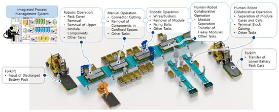
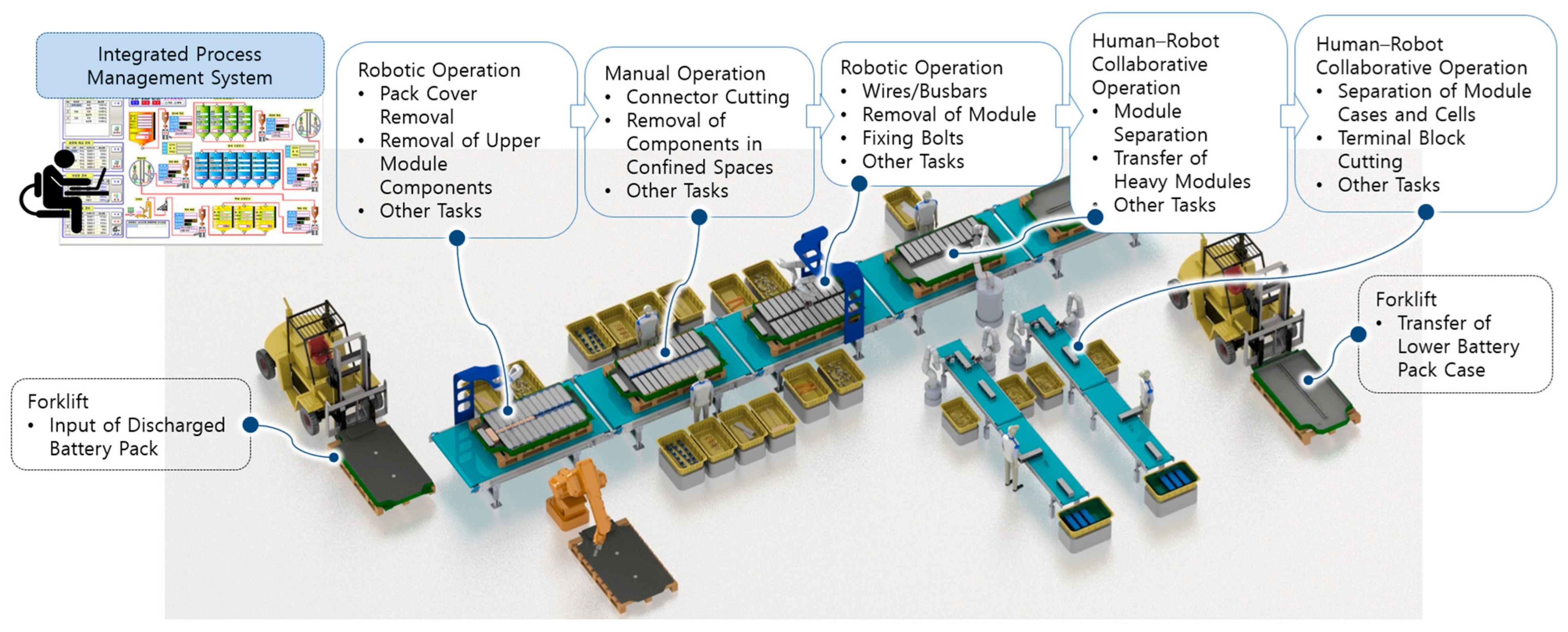
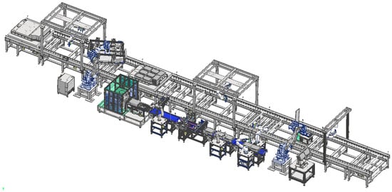
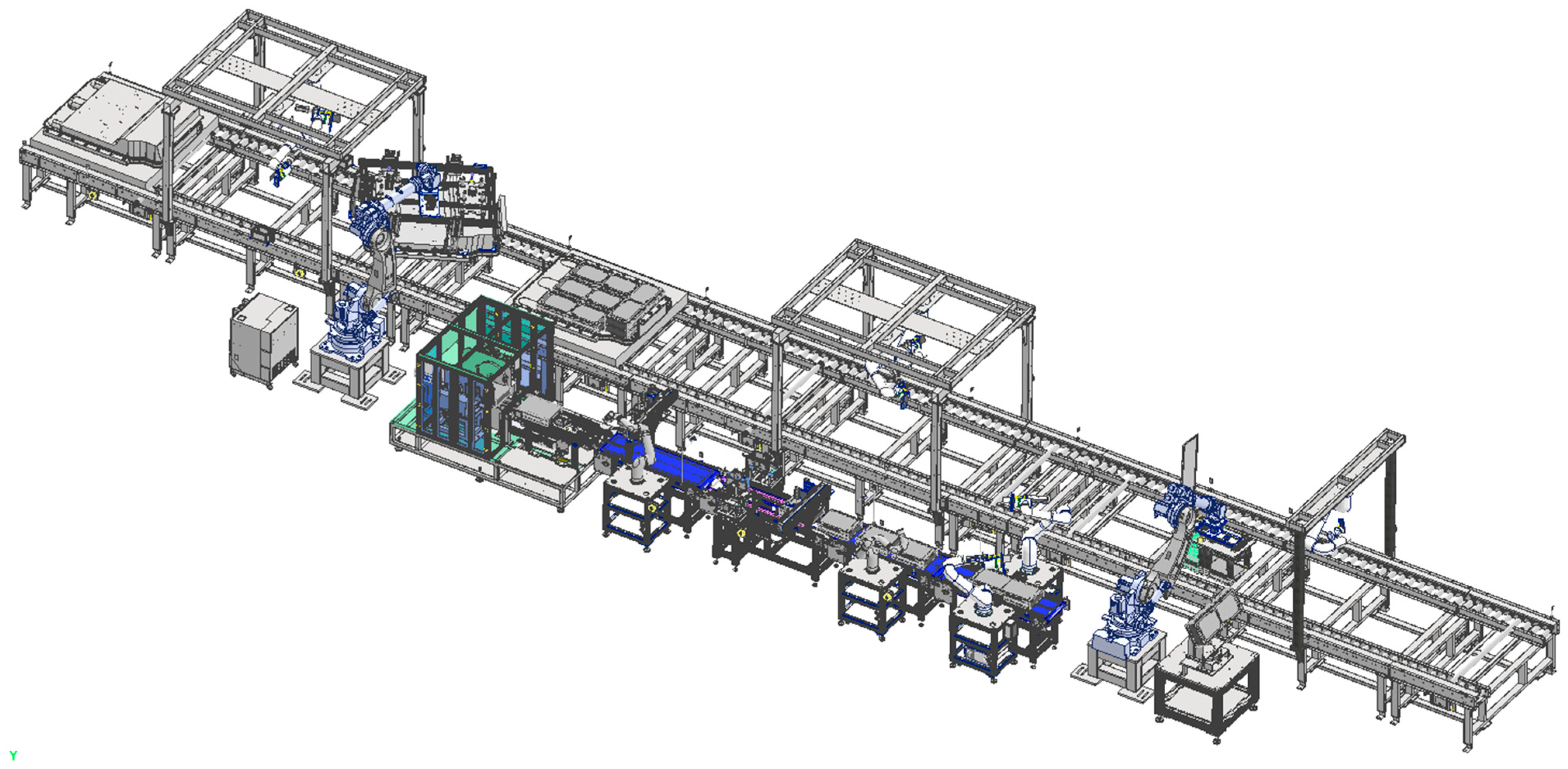
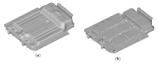
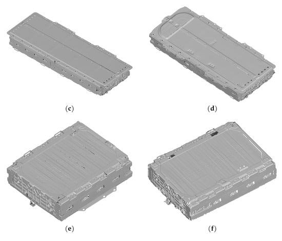
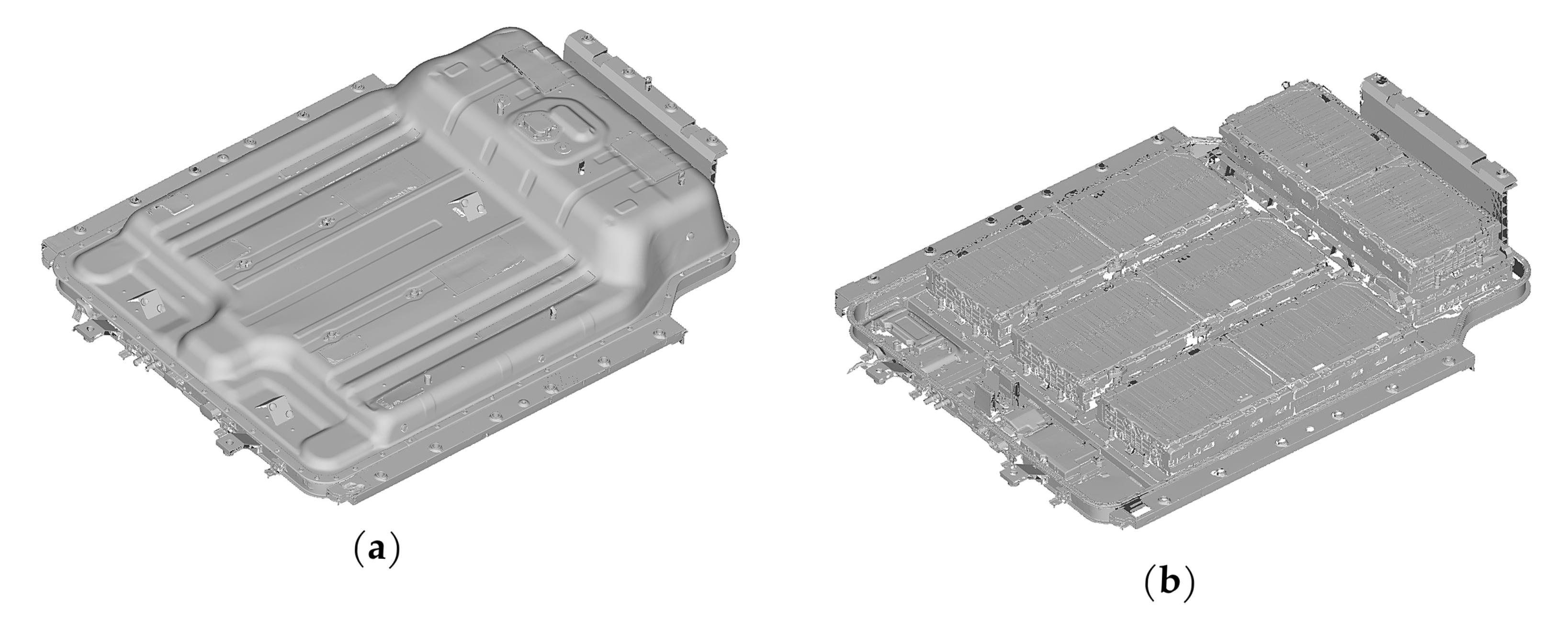
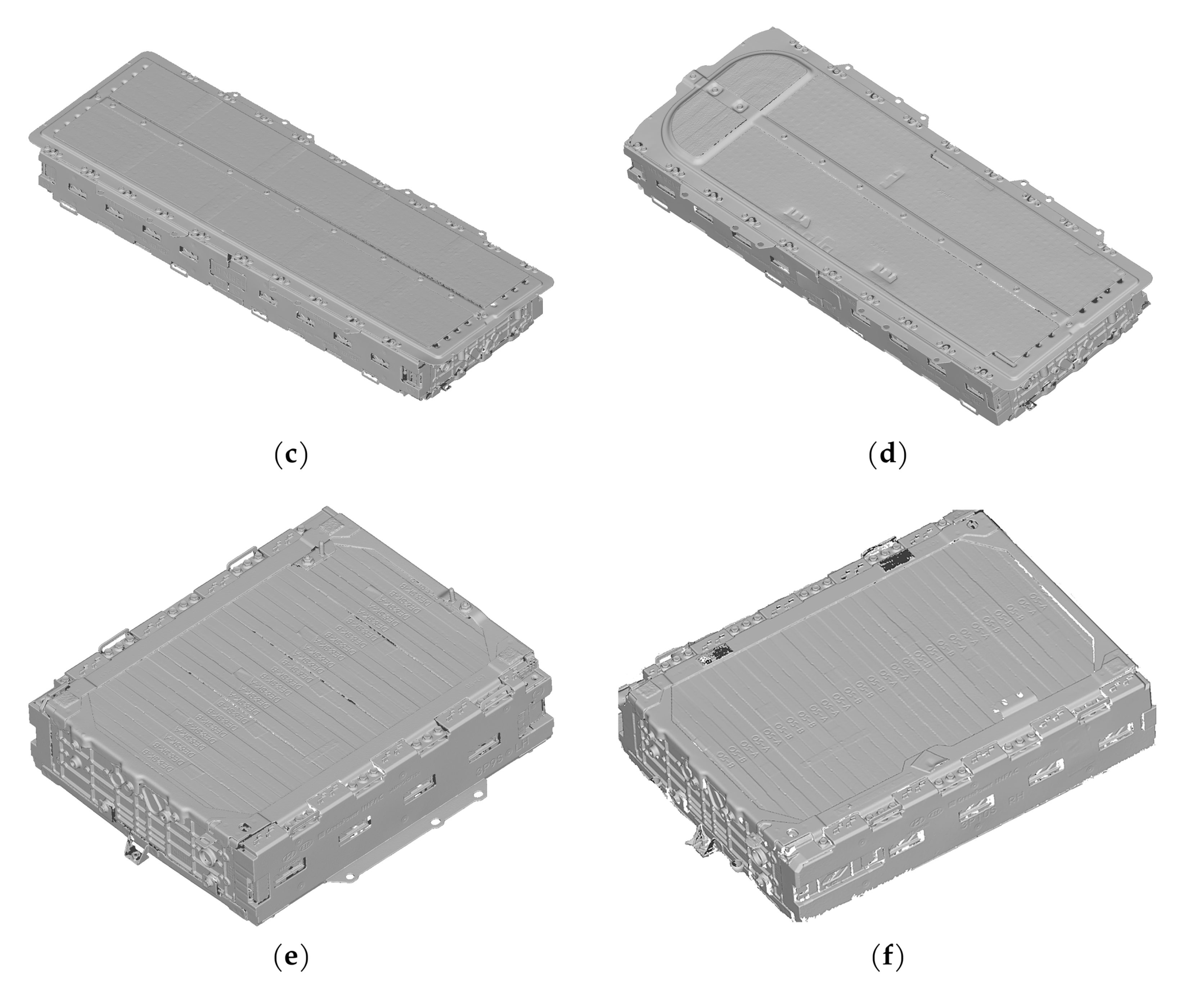
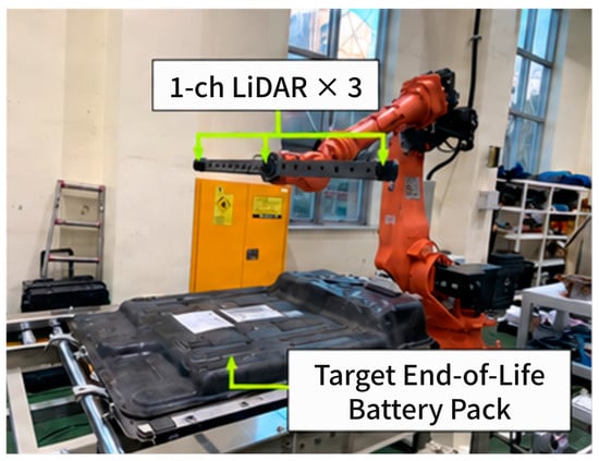
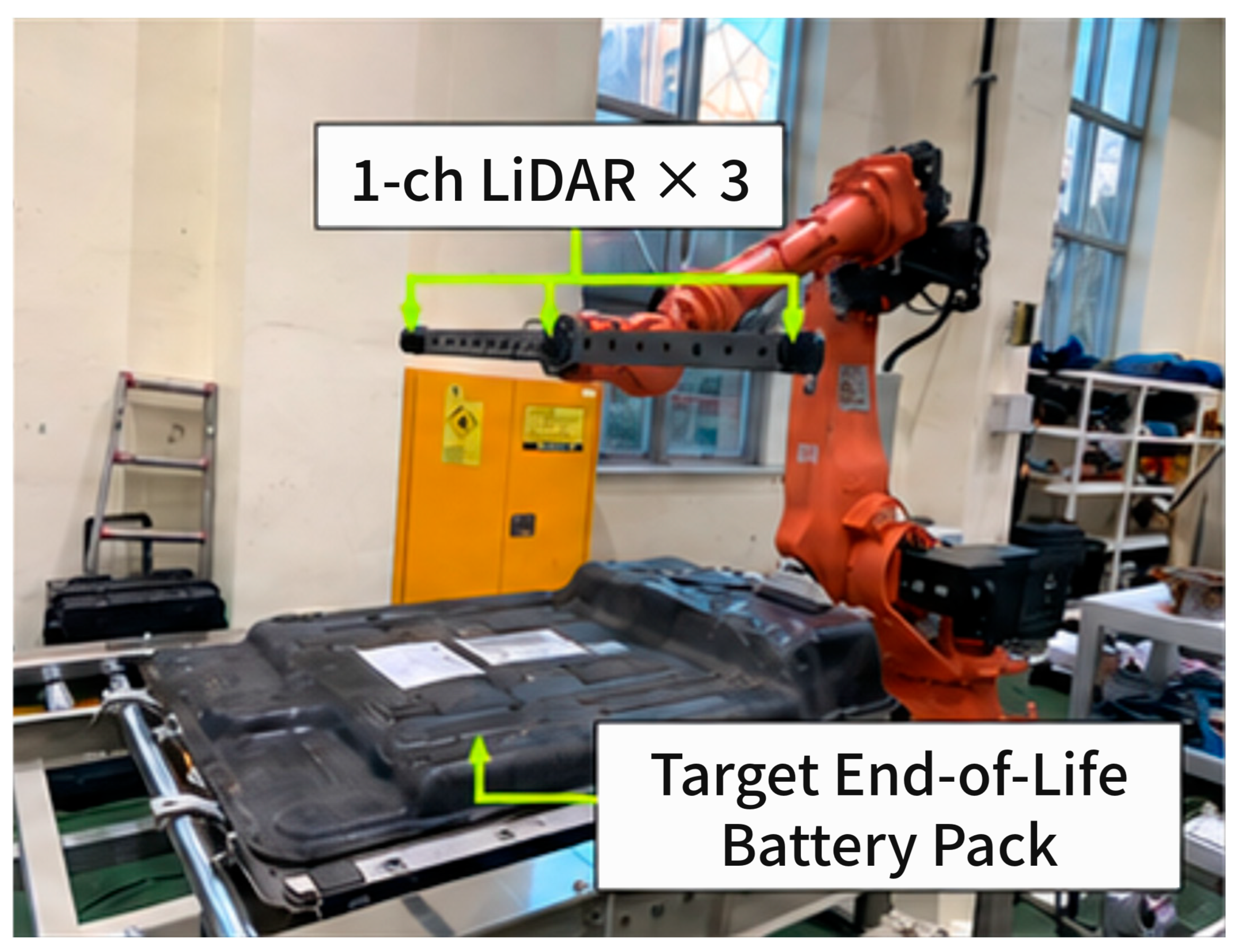
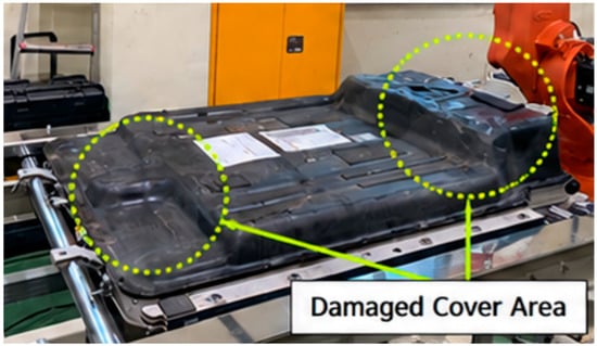
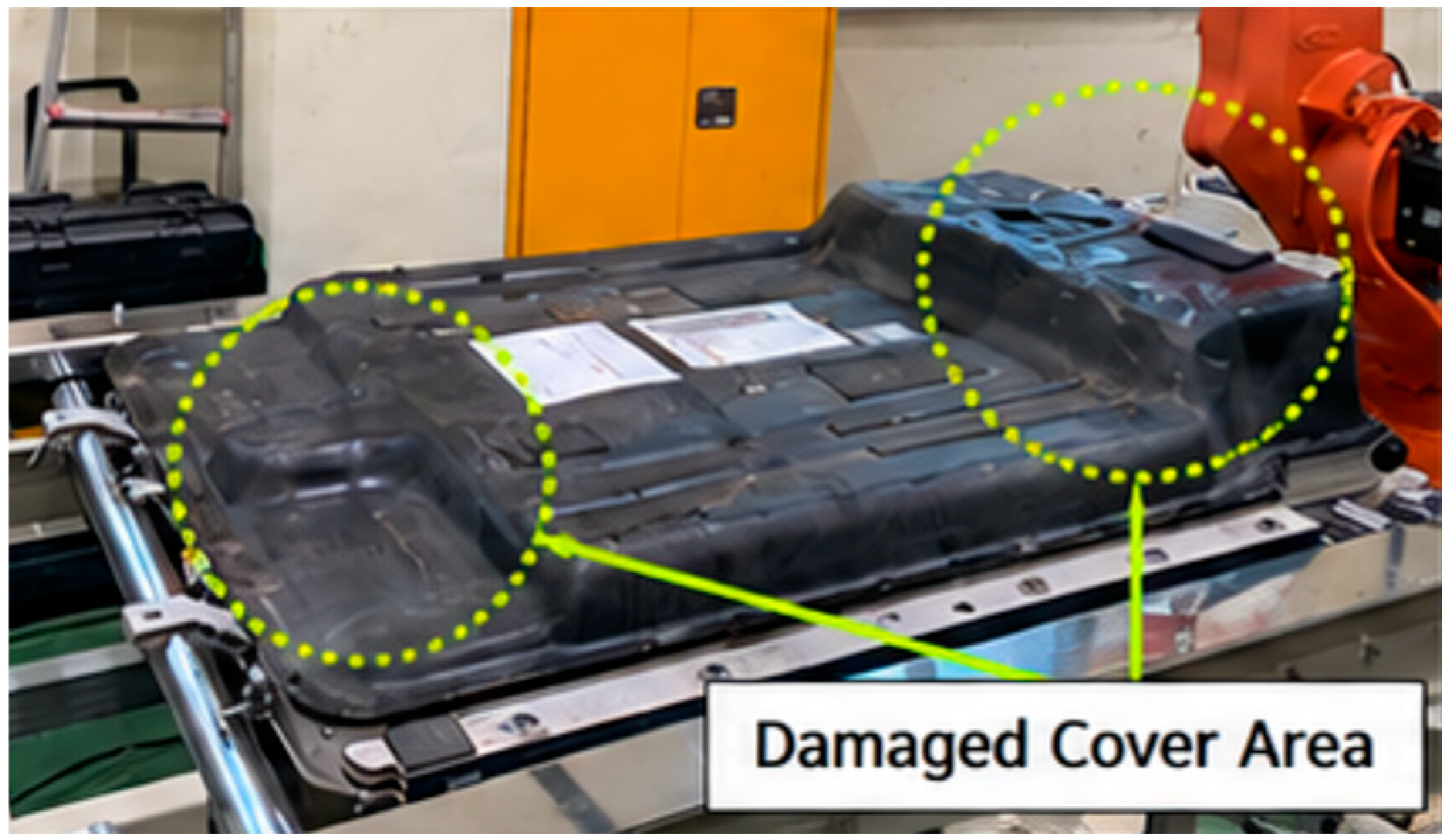
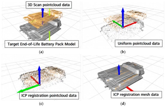
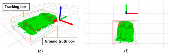
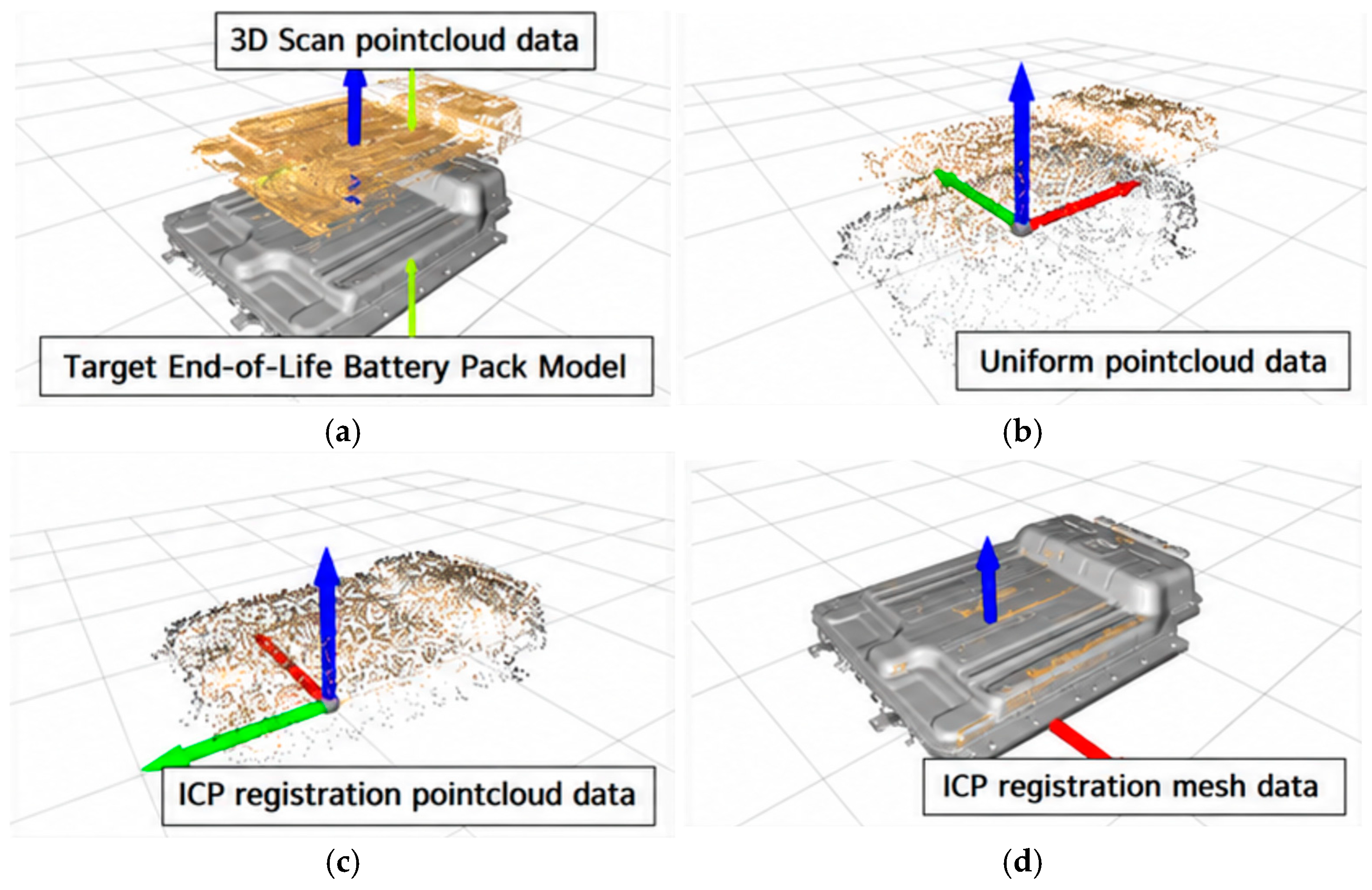
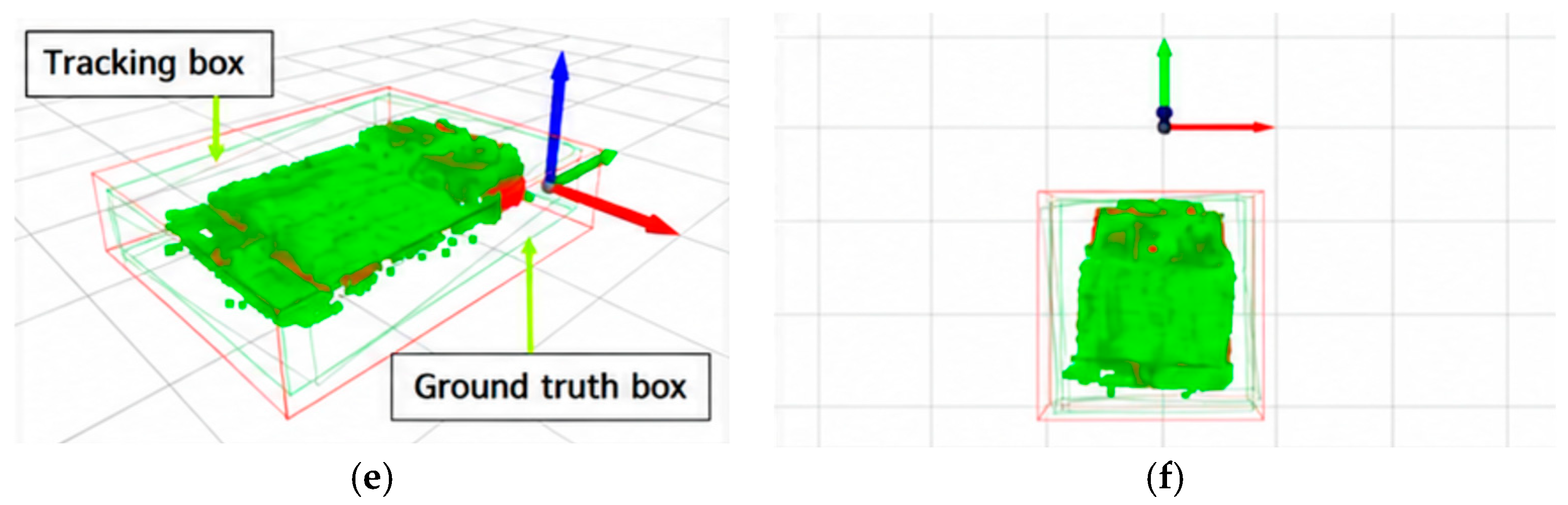
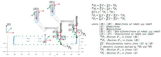
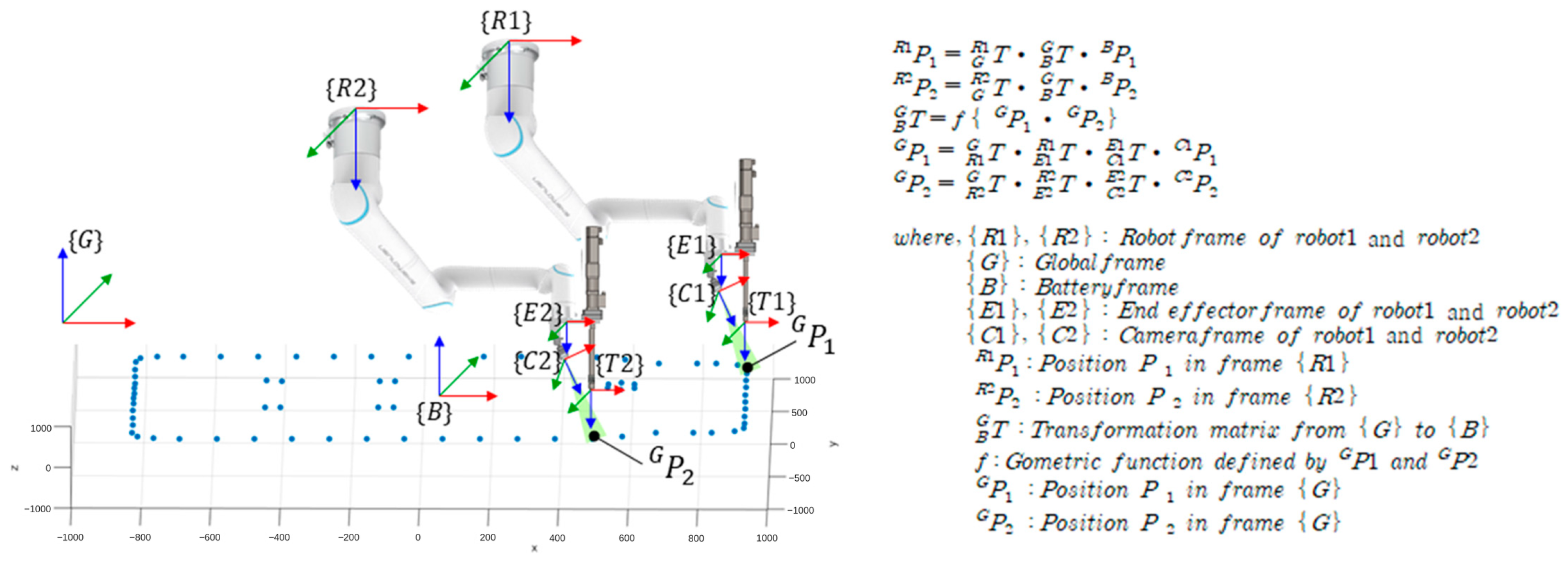
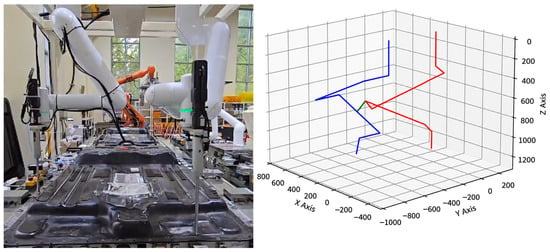
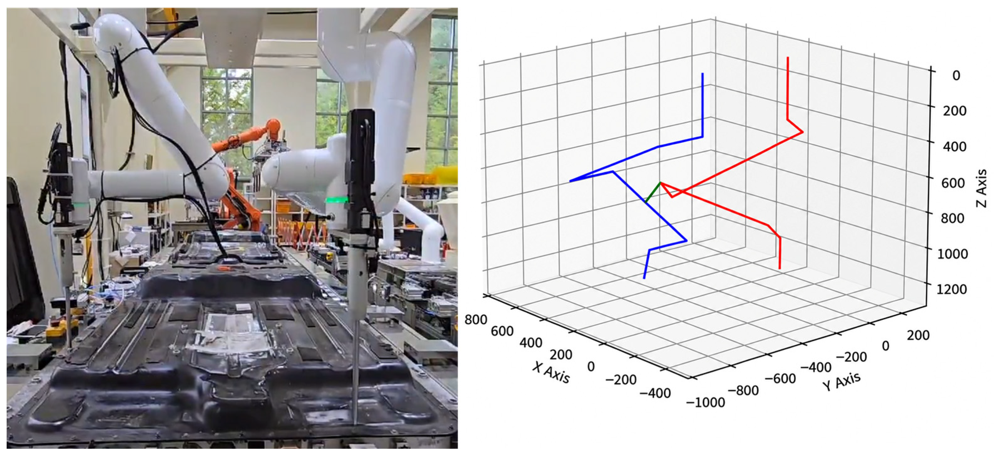
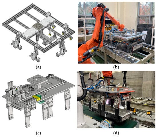
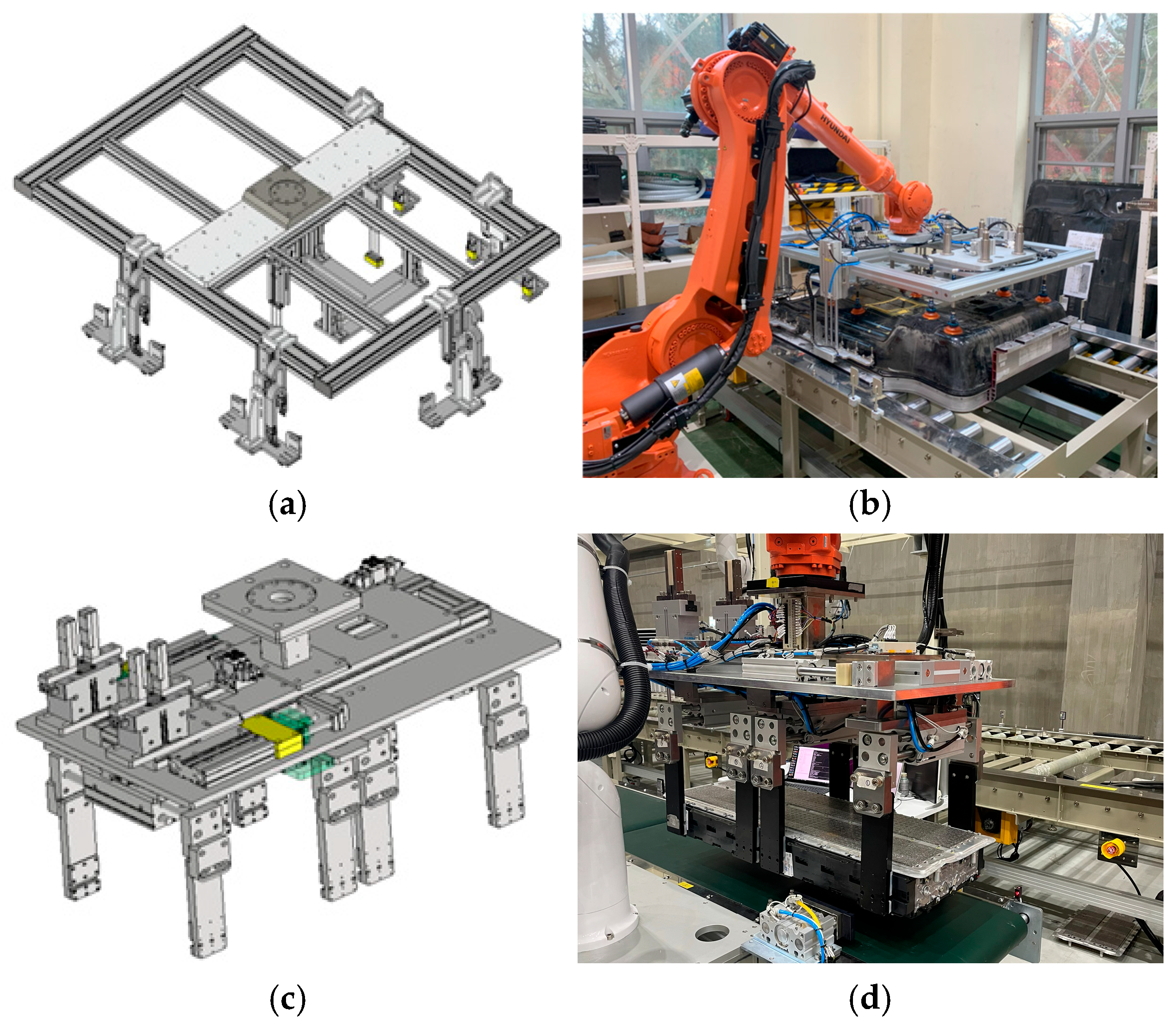
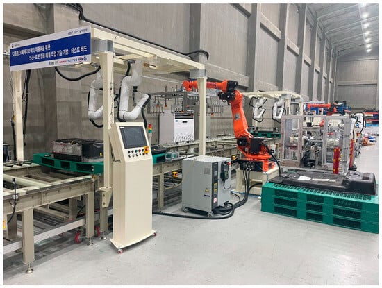
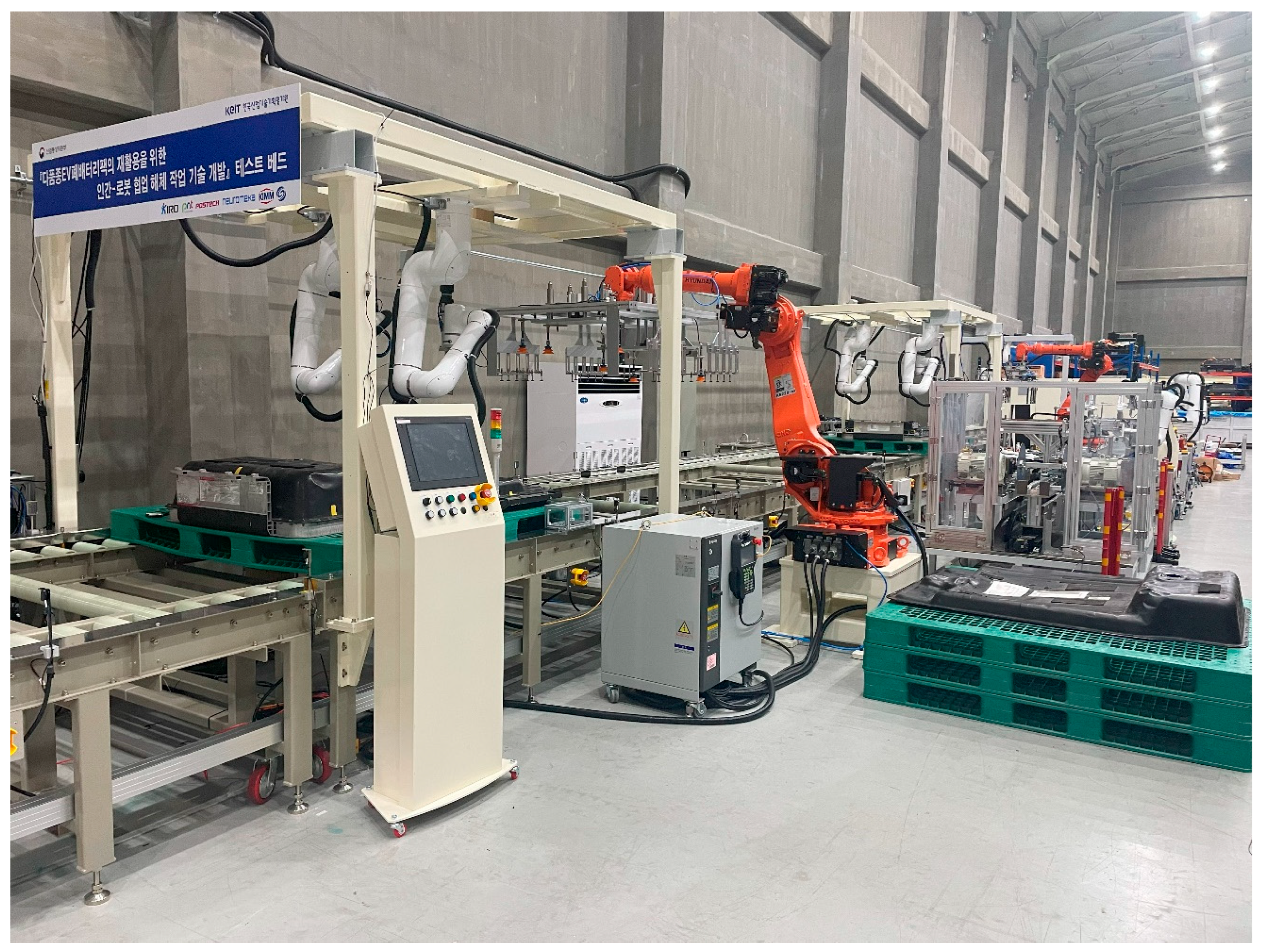
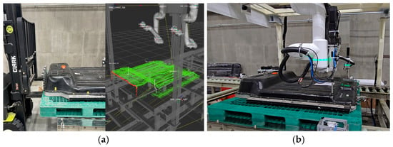
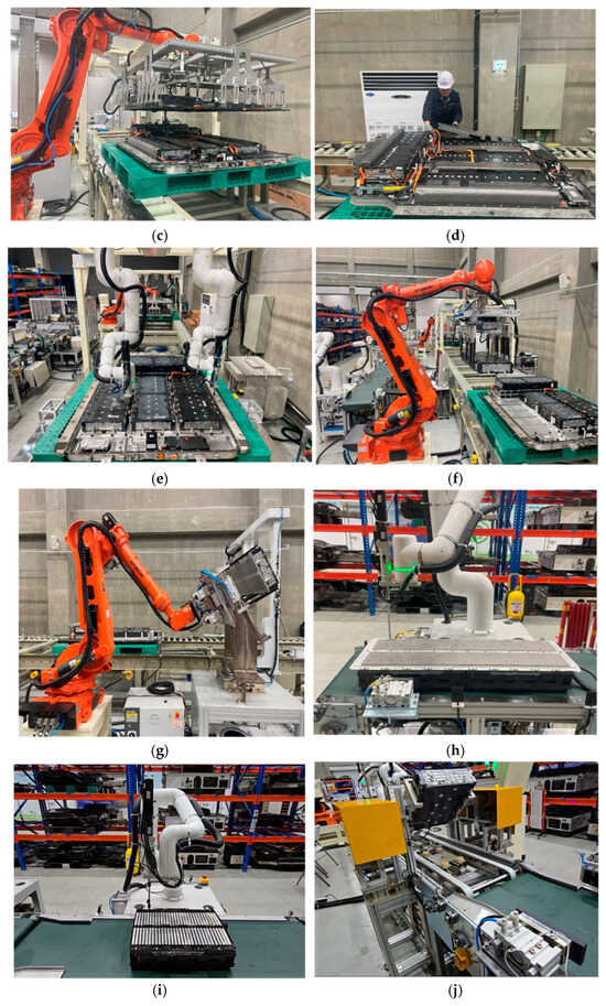
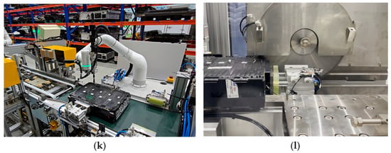
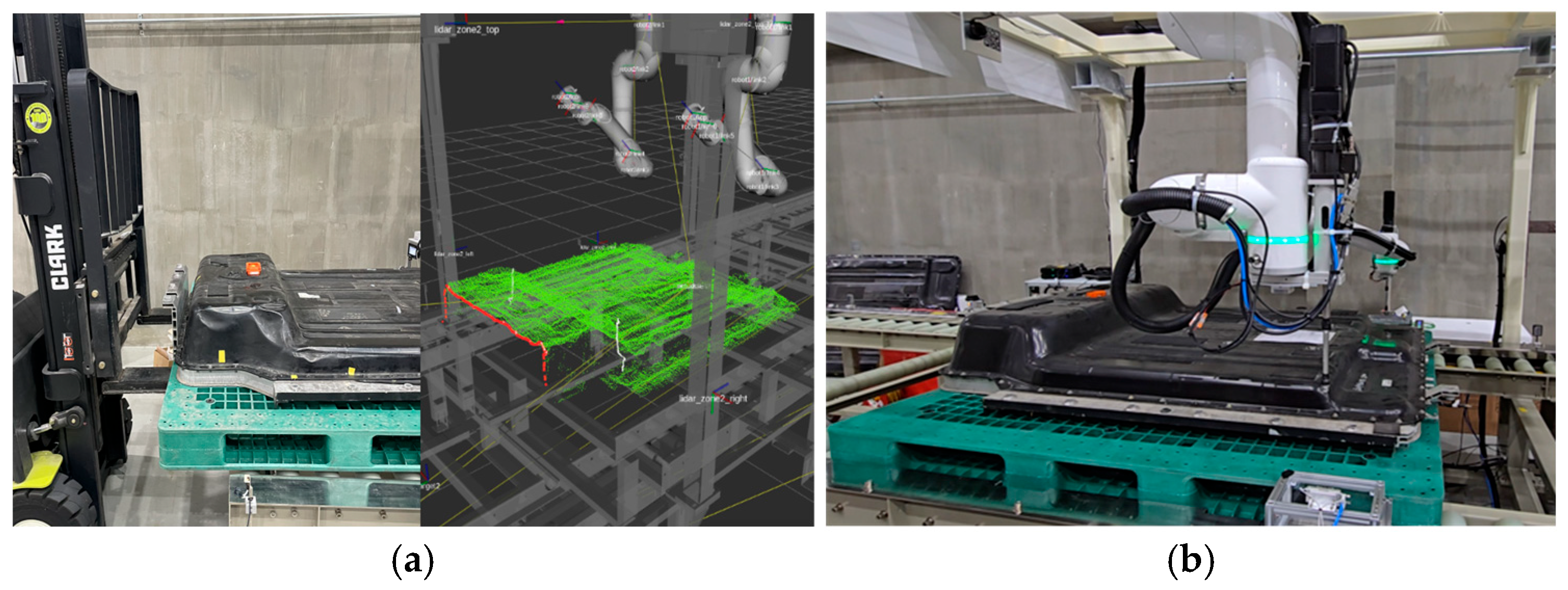
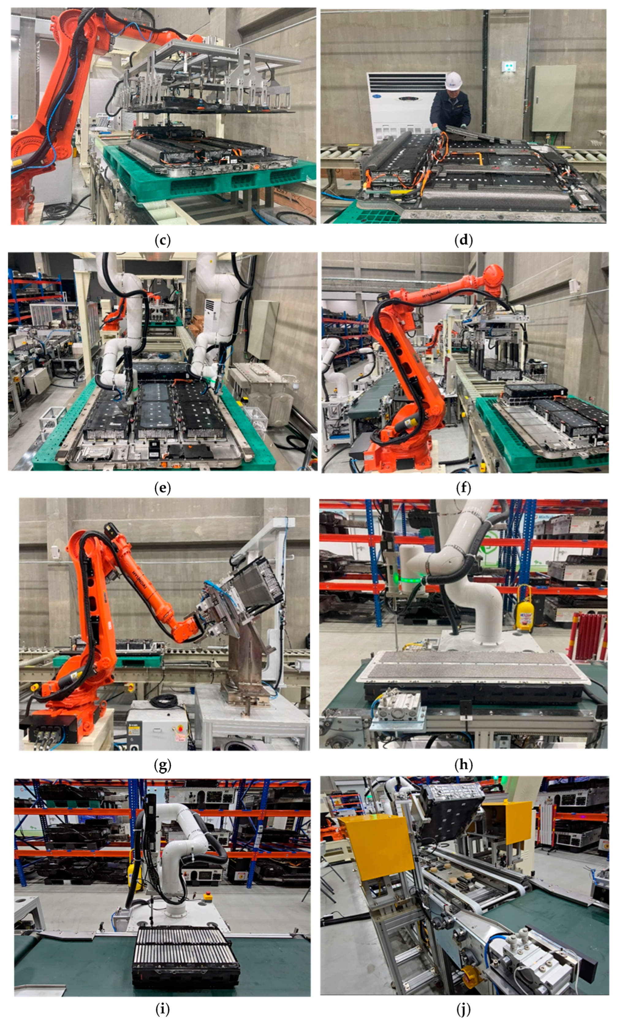
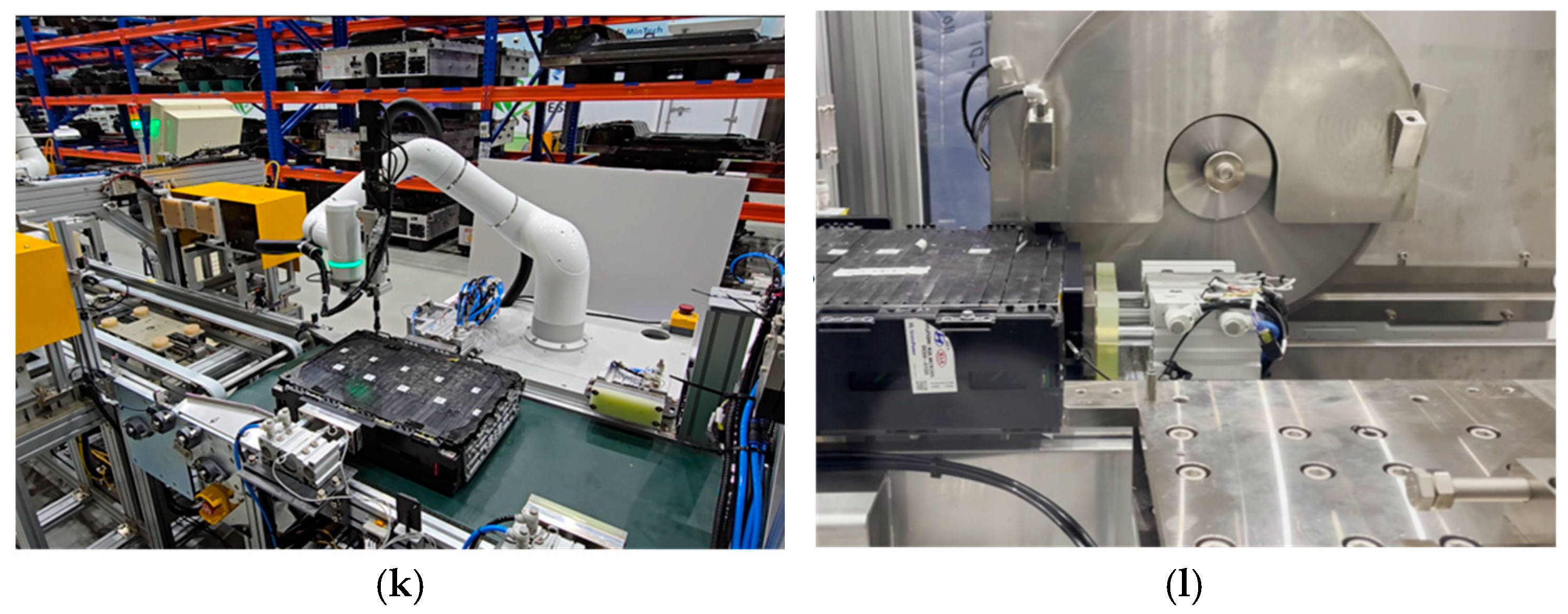
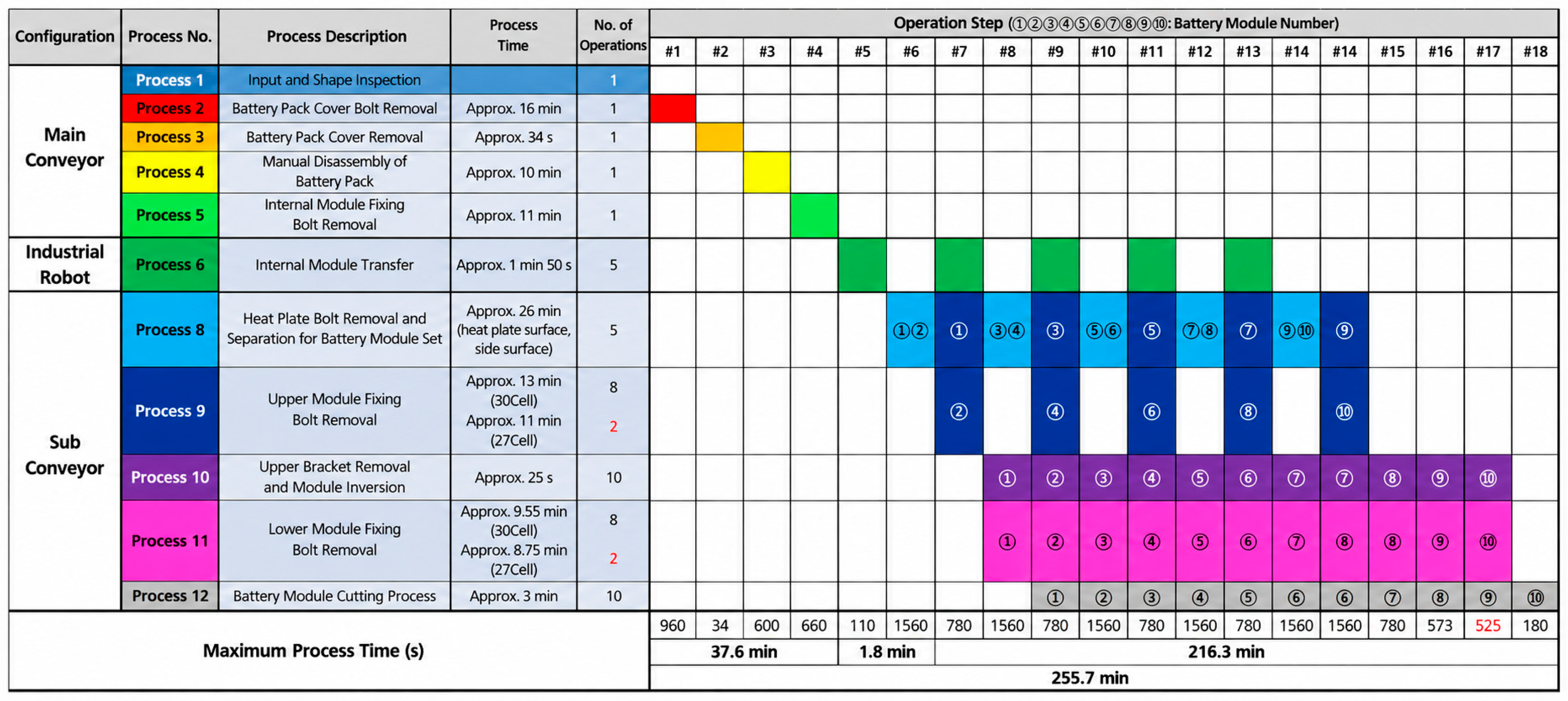

Disclaimer/Publisher’s Note: The statements, opinions and data contained in all publications are solely those of the individual author(s) and contributor(s) and not of MDPI and/or the editor(s). MDPI and/or the editor(s) disclaim responsibility for any injury to people or property resulting from any ideas, methods, instructions or products referred to in the content. |
© 2026 by the authors. Licensee MDPI, Basel, Switzerland. This article is an open access article distributed under the terms and conditions of the Creative Commons Attribution (CC BY) license.