


Abstract
Cage pocket wear and thermal deformation can jointly alter ball–cage contact conditions in high-speed bearings. However, their coupled effects on nonlinear bearing dynamics remain insufficiently studied. A nonlinear dynamic model is developed to account for nonuniform cage thermal deformation, frictional heat generation, wear-induced pocket clearance, and local stiffness variation. These effects are coupled through the ball–cage pocket contact relationship. System responses at different rotational speeds and wear depths are obtained by numerical integration. Nonlinear behavior is characterized using bifurcation diagrams, maximum Lyapunov exponents, phase trajectories, Poincaré sections, and frequency spectra. The results show that the cage temperature field and thermal deformation are nonuniformly distributed, with larger values near the cage pockets. Increasing cage pocket wear changes the bifurcation behavior and causes an earlier transition to chaos. When the wear depth increases from 0.5 to 1.5 mm, the onset speed decreases from 9600 to 8500 rpm. The spindle rotational frequency and cage rotational frequency are identified in both numerical and experimental spectra. Combination frequency components are also observed. For the upper sideband fs + fc, the difference between the experimental and numerical peak amplitudes is 5.31%. These results show that increasing cage pocket wear advances the transition to chaotic motion. The agreement between numerical and experimental characteristic frequencies also supports the proposed model under the investigated conditions.
1. Introduction
Bearings are key supporting components in aerospace systems, precision machine tools, and high-speed rotating machinery. Their operating condition directly affects load transmission, motion accuracy, and dynamic stability [1,2]. Under high-speed or variable operating conditions, repeated ball–cage interaction, relative sliding, and intermittent impacts may occur. These effects can cause local material loss and gradually increase cage-pocket clearance [3,4,5]. Meanwhile, frictional contact generates heat, which may lead to thermal expansion and deformation of bearing components [6,7]. Therefore, the coupled effects of cage-pocket wear and thermal deformation are important for understanding the dynamic behavior of high-speed bearings.
The cage plays an important role in maintaining ball spacing and guiding rolling-element motion. Previous studies have shown that cage motion is sensitive to structural parameters and operating conditions, including unbalance, run-out, mounting configuration, rotational speed, and lubrication conditions [8,9,10]. Cage slip and other abnormal motion characteristics have also been investigated under different operating conditions [11,12,13]. Micro-geometric deviations and cage-related structural parameters can further affect cage motion and stability [14,15,16]. Numerical and experimental studies have examined rolling-element–cage collision, contact forces, and cage vibration [17,18,19]. The effects of rolling-element interaction, pocket geometry, and cage guidance on cage trajectories and contact states have also been investigated [20,21,22]. Recent research has further considered the combined influence of cage-pocket wear and thermal expansion on nonlinear bearing dynamics [23]. However, the coupled effects of nonuniform thermal deformation and local cage-pocket wear remain insufficiently investigated.
Thermal effects become increasingly important during high-speed bearing operation. Friction and relative sliding at rolling contacts and cage-related interfaces generate heat, while lubrication conditions influence heat dissipation and temperature distribution [24,25]. Preload variation and temperature-dependent stiffness can further affect the thermomechanical behavior of high-speed bearings [26,27,28]. Internal clearance also influences rolling-element trajectories, contact conditions, and system dynamics [29,30]. However, the dynamic response resulting from the interaction among nonuniform cage temperature, local thermal deformation, and progressive cage-pocket clearance variation has not been fully characterized.
In this study, a nonlinear bearing model is established to investigate the coupled effects of nonuniform cage thermal deformation and local cage-pocket wear. Wear-induced clearance variation, local stiffness degradation, and repeated impact in the worn region are incorporated into the model. Frictional heat generation at the ball–cage-pocket, cage–guiding-surface, and ball–raceway contacts is calculated. Finite-element thermal analysis is performed to obtain the nonuniform temperature and thermal-deformation distributions of the cage. The local additional clearance and stiffness variation are introduced into the Hertzian contact relationship at the ball–cage-pocket interface. Numerical integration is used to compare the dynamic responses under thermal deformation alone and under coupled thermal deformation and pocket wear. Bifurcation diagrams, maximum Lyapunov exponents, phase trajectories, and Poincaré sections are employed to characterize the nonlinear dynamic states. Experimental vibration tests are finally conducted to compare the measured and numerical vibration responses.
2. Dynamic Modeling of the Bearing
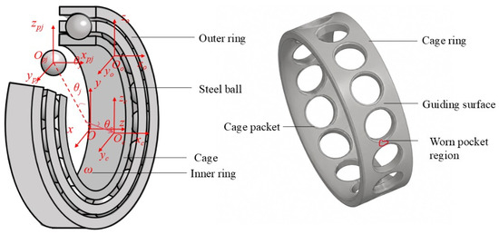
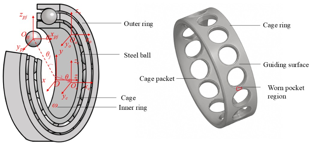
Six coordinate systems are defined to describe the bearing motion, as shown in Figure 1. The global coordinate system is fixed at the center of the outer ring. The outer ring remains stationary. Local coordinate systems are defined for the inner ring, outer ring, cage, ball(j), and corresponding cage pocket. Their axial directions are parallel to the bearing axis. Their radial directions follow the geometry of each component. The inner ring rotates with the shaft. Radial vibration of the inner ring is also considered. The cage rotates around the bearing axis. The pocket coordinate system describes the relative displacement between the ball and cage pocket. It is also used to calculate the contact deformation and contact force.
Figure 1.
Coordinate systems used in the bearing model and geometric description of the localized cage pocket wear region.
2.1. Temperature Field and Thermal Model of the Bearing Cage
Multiple contacts occur during high-speed operation. They involve balls, the cage, bearing rings, and guiding surfaces. Relative motion also occurs at these contacts. Friction, sliding, and local impacts convert part of the mechanical energy into heat. This raises temperatures in cage pockets, guiding surfaces, and local worn regions. Thermal expansion then changes cage pocket dimensions, guiding clearance, and local structural stiffness. These changes affect ball–cage contact conditions. Accordingly, heat-generation and thermal-deformation models are established for the relevant cage regions.
The cage is guided by the outer ring in the present model. This configuration is consistent with the experimental bearing. The outer ring provides the guiding surface for cage motion. Therefore, the guiding contact is defined between the outer surface of the cage and the corresponding surface of the outer ring.
This study considers heat generation in cage-related regions. The main heat sources are frictional heat at ball–cage pocket contacts, cage–guiding surface contacts, and additional contacts in worn regions. Based on established formulations for bearing contact interfaces [31,32], the heat-generation model describes frictional heat generation at the corresponding contact regions. These three heat contributions are denoted by , , and , respectively. The total heat generated in these regions is denoted by , and expressed as:
where , , and represent the frictional heat-generation rates at ball–cage pocket contacts, cage–guiding surface contacts, and local contacts in worn regions, respectively. is the total heat-generation rate in the cage-related contact regions, while ωc is the cage angular velocity. N is the number of balls involved in cage pocket contacts. μfp, μfg are the friction coefficients at ball–cage pocket and cage–guiding surface contacts, respectively. Qpi, Qg are the corresponding normal contact loads. ap, lp are the equivalent contact half-width and contact length of the cage pocket contact region. Similarly, ag, lg are the equivalent contact half-width and contact length of the guiding surface contact region. Nb is the number of local contact points. μbj, Fbj, and vbj are the friction coefficient, contact force, and relative sliding velocity at the jth local contact point, respectively.
To further characterize the lubrication condition at the pocket interface, the minimum lubricant-film thickness is estimated using an elastohydrodynamic lubrication relation for elliptical contact [33]:
where hmin is the estimated minimum lubricant-film thickness at the ball–cage pocket interface; Rx is the equivalent radius of curvature in the rolling direction; U, G and W are the dimensionless speed, material, and load parameters, respectively; η0 is the dynamic viscosity of the lubricant at ambient pressure; ue is the lubricant entrainment velocity; E′ is the equivalent elastic modulus; αp is the pressure–viscosity coefficient of the lubricant; Fn is the normal contact load; and k is the ellipticity parameter of the contact.
Heat is also generated at the ball–raceway contacts. According to the empirical heat-generation model for angular contact ball bearings [24], the heat generation at the raceway contacts is expressed in piecewise form as:
where Hfv is the heat generated at the ball–raceway contacts, n is the bearing rotational speed. fv is the coefficient related to the bearing structure and load condition and is set to 0.001. P1 is the calculated bearing load, and dv is the bearing pitch diameter. f0 is related to the bearing type and lubrication condition and is set to 1.7 for the oil–air-lubricated angular contact ball bearing considered in this study. ν is the kinematic viscosity of the lubricant. The empirical formulation is applied to the 7006C angular contact ball bearing under the specified oil–air lubrication condition. The investigated rotational speed range is from 0 to 40,000 rpm. The corresponding load and lubricant viscosity conditions follow those used in the present model. The two expressions in Equation (3) are selected according to the νn criterion. These empirical coefficients are used only for the investigated conditions and are not assumed to be universally applicable outside this range.
Relative sliding also occurs among balls, the cage, and bearing rings during high-speed operation. According to the frictional power-loss and heat-generation relationship commonly used for rolling-bearing contacts [32,34], the frictional power loss at the contact interfaces is converted into heat. At the ith sliding contact point, μsi, Fsi, vsi represent the friction coefficient, contact force, and relative sliding velocity, respectively. The sliding-friction heat and total heat of the bearing contact system are expressed as:
where is the heat-generation rate caused by relative sliding, while is the total heat-generation rate of the bearing contact system. Ns denotes the number of sliding contact points considered in the model.
The regional temperature changes are used to calculate the thermal deformation of the cage. Based on the conventional linear thermal-expansion relationship used in bearing thermal analysis [32], the thermal deformation of each representative region is calculated as:
where ur, up, ug, ub represent the thermal deformations of the cage ring, cage pocket, guiding surface, and worn pocket region, respectively. αc is the linear thermal expansion coefficient of the cage material. Rc is the cage pitch-circle radius, while rp and rg are the characteristic radius of the cage pocket and the equivalent radius of the guiding surface, respectively. lb is the characteristic length of the worn pocket region. ΔTc, ΔTp, ΔTg, ΔTb are the corresponding temperature rises. ΔTc denotes the overall cage temperature rise used to estimate the equivalent thermal deformation of the cage ring.
The accumulated heat used in the temperature-rise calculation is defined as , where denotes the heat-generation rate and Hi denotes the corresponding accumulated heat.
For an analytical estimate of the relationship between regional heat accumulation and temperature rise, a lumped-parameter approximation is adopted as:
where mc is the cage mass; C is the specific heat capacity of the cage material. The expression describes the effect of regional heat input on local temperature rise for the same cage material.
Equation (6) relates accumulated heat to temperature rise using a lumped-parameter approximation. Together with Equation (5), it establishes the relationship between heat generation and thermal deformation. ANSYS Workbench 2022 R1 is used to evaluate the nonuniform temperature field of the cage. The calculated frictional heat-generation rates are applied as surface heat fluxes to the corresponding contact regions. Steady-state analysis determines the spatial temperature distribution. Transient analysis provides the temperature histories. Table 1 summarizes the material properties, mesh settings, and thermal boundary conditions.
Table 1.
Main parameters and boundary conditions of the finite element thermal model.
Representative temperatures are extracted from the ANSYS results for the cage and its selected regions. The corresponding temperature rises are substituted into Equation (5) to calculate equivalent thermal deformations. These deformations are incorporated into the dynamic model through corrections to the effective cage-pocket clearance. The corrected clearance modifies contact deformation and contact force.
If the initial contact deformation is denoted by δ0, the actual contact deformation considering thermal deformation is expressed as:
δn = δ0 − ΔδT
When wear is further considered, local additional clearance in worn regions reduces the effective contact indentation between balls and cage pockets. The actual contact deformation under the combined effects of temperature rise and wear is expressed as:
δns = δ0 − ΔδT − Δδs(θ)
If wear depth is hs and wear width is bs, the dimensionless parameter is defined as:
where λh, βs, χT are the dimensionless parameters of wear depth, wear width, and thermal deformation, respectively. hs and bs represent wear depth and wear width. h and b represent the original local thickness and width, respectively. ΔhT is the temperature-induced deformation in the thickness direction.
Figure 2 schematically illustrates the evolution of geometric parameters under the coupled effects of cage pocket wear and thermal deformation.Considering the combined effects of wear depth and thermal deformation on local thickness, the effective thickness in the worn region is given by:
he = h(1 − λs − χT)
Figure 2.
Schematic illustration of geometric-parameter evolution under the coupled effects of cage pocket wear and thermal deformation.
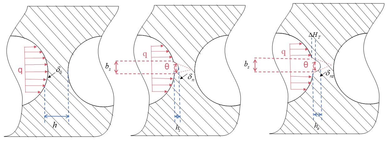
According to Equations (7)–(10), thermal expansion and material removal change local pocket geometry and effective contact clearance. These changes affect ball–cage pocket contact indentation and local load-carrying capacity, requiring a coupled contact-force formulation.
2.2. Force Analysis and Dynamic Model of the Cage
During high-speed operation, ball–cage pocket contact can transition between continuous and intermittent states. Thermal deformation changes the geometry of the cage pocket contact region. This alters contact position, contact area, and load distribution. To characterize this effect, a thermal deformation influence coefficient is introduced. Tangential actions along the two principal directions of the contact region are integrated as:
where ζ and η are the local coordinates in the contact region.
Thermal deformation alters the effective dimensions of the cage pocket contact region. Its effect is incorporated into the semi-major and semi-minor axes of the contact ellipse for contact stress and force calculations. The corrected contact dimensions are expressed as:
After thermal deformation, ball–cage pocket contact stress is determined using the corrected contact semi-axes. An elliptical contact stress distribution is then adopted to calculate tangential shear stress and friction force at the contact surface as:
where τ is the tangential shear stress in the contact region; ηT is the thermal deformation influence coefficient characterizing the effect of temperature rise on the contact dimensions.
The model accounts for thermal deformation by correcting the contact indentation. The normal contact force and tangential friction force at the ball–cage pocket contact are expressed as:
where KH is the Hertzian contact stiffness coefficient; δ0 is the initial contact deformation. ΔδT is the change in ball–cage pocket contact clearance caused by temperature rise. ui is the thermal deformation at the ith local position. si is the weighting coefficient for the effect of local thermal deformation on contact clearance. n is the number of local deformation terms used in the equivalent thermal deformation calculation.
The local thermal deformation ui is determined from the corresponding regional temperature response obtained by the ANSYS thermal analysis in conjunction with the thermal-expansion relation given in Equation (5). The equivalent thermal-clearance variation ΔδT is subsequently evaluated through the weighted contribution of the local thermal deformations and incorporated into Equation (14) to correct the ball–cage pocket contact indentation. In this manner, the nonuniform thermal response is introduced into the dynamic contact-force formulation through the temperature-induced modification of the effective contact deformation.
Cage pockets are affected by both temperature rise and wear during operation. Wear introduces additional clearance in local pocket regions, reducing ball–cage pocket contact deformation. To describe the circumferential wear distribution, an angular variable θ is introduced. The worn region is defined within [θs,θe], and the local geometric defect is expressed as:
where Δδs(θ) is the local additional clearance caused by wear at angular position θ. hs is the maximum wear depth, while Γ(θ) is the normalized wear-depth distribution function. θs and θe define the start and end angles of the worn region, respectively. Outside this region, Γ(θ) = 0. Within the worn region, Γ(θ) varies with angular position to describe the circumferential wear-depth distribution.
The function Γ(θ) is introduced as an idealized representation of local cage pocket material loss. It is not fitted to a measured wear profile. A cosine function is used to describe the defect distribution. The defect depth is zero at both boundaries of the worn region. It changes smoothly to the maximum defect depth inside the worn region. This form avoids abrupt geometric discontinuities in the contact calculation.
Thermal deformation further modifies the local effective thickness. For reduced-order dynamic modeling, the cage bridge adjacent to the worn pocket is approximated as an equivalent rectangular section. For this section, the second moment of area depends linearly on the effective width and cubically on the effective thickness. The local bending stiffness is related to the sectional second moment of area. The effects of wear and thermal deformation are therefore introduced into the equivalent second moment of area and local structural stiffness as follows:
where Is and I0 denote the equivalent second moments of area of the local cage bridge in the damaged state and intact state, respectively. Kse, K0 are the corresponding local stiffness values. b and h denote the width and thickness of the equivalent rectangular section. βs represents the reduction in effective width caused by wear. λs represents the reduction in effective thickness caused by wear. χT represents the change in effective thickness caused by thermal deformation. χl is the stiffness correction coefficient.
This formulation is used as an equivalent stiffness approximation. It does not explicitly resolve local stress concentration or multi-axial deformation of the cage bridge.
Figure 3 presents a schematic force analysis of the ball. The arrows indicate the directions of the forces acting on the ball.
Figure 3.
Schematic illustration of the force analysis.
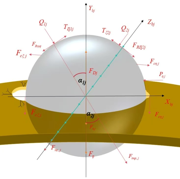
Wear changes pocket contact deformation by introducing additional clearance. It also reduces local structural stiffness. As balls enter or leave the worn region, the contact state changes between continuous and intermittent contact. Based on these effects, a pocket contact-force model under wear is established.
The equivalent contact stiffness is obtained from the Hertzian contact stiffness and local cage structural stiffness as:
According to the nonlinear Hertzian contact relationship, the normal contact force depends on the actual contact deformation. When the deformation is less than or equal to zero, the ball and cage pocket are separated. The normal contact force and tangential friction force at the jth ball–cage pocket contact under wear are expressed as:
where Keq,j denotes the combined equivalent stiffness of the jth ball–cage pocket contact, and μj denotes the corresponding equivalent friction coefficient.
The normal contact force and tangential friction force at the ball–cage pocket contact are expressed as:
where Qij is the normal contact force between the jth ball and the ith raceway. i = 1,2 correspond to the inner and outer raceways, respectively. δ0 is the initial contact deformation, while Δδn is the correction caused by temperature rise, wear, or local deformation. Contact exists when the corrected deformation is greater than zero; otherwise, the ball and raceway are separated.
Relative sliding between balls and cage pockets generates tangential friction. Its magnitude depends on the normal contact force, while its direction opposes the relative sliding direction. The tangential friction force is expressed as:
where vbc,j, μbc,j are the relative sliding velocity and equivalent friction coefficient between the jth ball and cage pocket, respectively. θj is the circumferential angular position of the jth ball.
When a ball passes the edge of the worn region, the contact state may change abruptly. The ball may undergo local unloading when entering the worn region and come into contact again when leaving it. When contact is restored, local compression and relative normal velocity generate an additional impact force. Assume that the re-contact compression of the kth ball at the worn-region edge is:
δimp,j ≡ δ0 − ΔδT − hsΓ(θj)
The model accounts for elastic compression and damping when contact is restored. The additional contact force at the worn-region edge is expressed as:
The damping coefficient is evaluated from the local equivalent contact stiffness as:
where Keq is the corresponding equivalent local contact stiffness. The coefficient 0.0154 is used in the present equivalent impact model. This formulation allows the damping coefficient to vary with the local contact stiffness instead of being prescribed as a constant.
The additional impact force acts only when contact between the ball and the worn-region edge is restored.
The normal contact force, tangential friction force, and worn-edge impact force at ball–cage pocket contacts are resolved in the fixed coordinate system. The resulting force components exerted by the jth ball on the cage are expressed as:
The cage is subjected to multiple loads under the combined effects of thermal deformation and cage pocket wear. These include pocket contact forces, guiding-surface forces, and intermittent impacts in worn regions. Compared with an intact cage pocket, wear changes contact from continuous to intermittent. This introduces additional time-varying loads, resulting in a nonuniform load distribution.
The cage dynamic equations consider normal contact forces, tangential friction forces, guiding-surface forces, and impact forces in worn regions. Translational and rotational inertia of the cage center of mass are also included. After summing the forces associated with all balls, the overall dynamic equilibrium equations of the cage are expressed as:
Each ball is subjected to raceway contact forces, tangential forces, rolling resistance, thermal-deformation-induced forces, and cage pocket forces during operation. Cage pocket wear introduces an additional impact force when the ball passes the edge of a worn region. These forces are resolved in the local ball coordinate system, and the dynamic equilibrium equation of the jth ball is expressed as:
Thermal deformation changes contact clearance, while cage pocket wear introduces additional clearance and reduces local stiffness. These effects govern contact, separation, and subsequent impact as balls pass through worn regions. The resulting contact forces are incorporated into the cage and ball dynamic equations. System dynamic states are then analyzed at different rotational speeds and wear depths.
3. Numerical Simulation and Analysis
The system response is obtained by numerical integration using the cage temperature field, thermal deformation model, and coupled dynamic equations. The main structural parameters of the 7006C angular contact ball bearing used in the numerical model are listed in Table 2. System vibration response and dynamic states are then examined at different rotational speeds and cage pocket wear depths under coupled thermal deformation and cage pocket wear.
Table 2.
Structural parameters of the 7006C angular contact ball bearing.
The nominal initial contact angle is set to 15°. During operation, the inner- and outer-raceway contact angles are updated according to the bearing kinematics and deformation state. As the rotational speed increases, the inner-raceway contact angle decreases, whereas the outer-raceway contact angle increases. The influence of thermal deformation on the contact geometry is also included in the calculation. Therefore, 15° represents only the initial contact angle and is not treated as a constant during operation.
3.1. Cage Temperature Field and Thermal Deformation Response
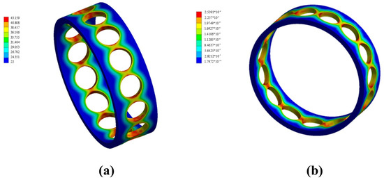
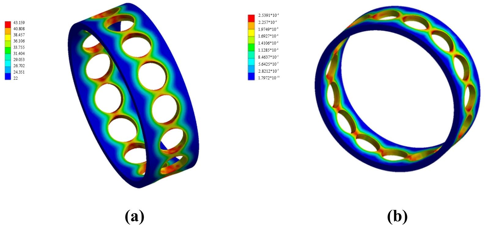
As shown in Figure 4a, the steady-state cage temperature exhibits a clear nonuniform distribution from 22 to 43.16 °C. High-temperature regions are mainly concentrated near the cage pocket edges and adjacent cage regions. The cage ring and guiding surface remain at relatively lower temperatures. This distribution is associated with local frictional heat generated at ball–cage pocket contacts.
Figure 4.
Temperature and thermal deformation distributions of the cage: (a) temperature distribution; (b) thermal deformation distribution.
Figure 4b shows the corresponding thermal deformation of the cage. The deformation distribution generally follows the high-temperature regions shown in Figure 4a. Larger deformation occurs near the cage pocket edges and adjacent cage regions. Smaller deformation appears in the cage ring and guiding surface. The maximum thermal deformation reaches 2.5391 × 10⁻⁴ mm, corresponding to approximately 0.254 μm. This distribution results from the nonuniform frictional heat generation and the resulting temperature gradient. Local thermal expansion changes the geometry of the cage pocket. This change modifies the effective contact clearance and the contact deformation between the ball and the cage pocket.
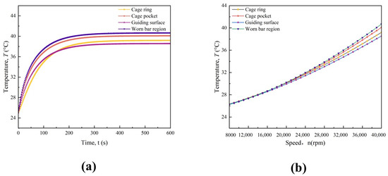
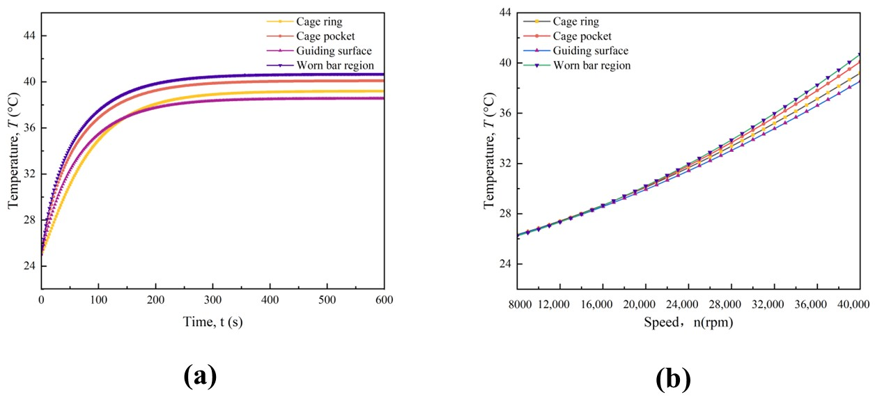
To further characterize the thermal behavior of the cage, the temperature responses of different cage regions are examined in terms of transient variation and rotational-speed dependence, as shown in Figure 5.
Figure 5.
Temperature responses of different cage regions: (a) predicted transient temperature; (b) steady-state temperature versus rotational speed.
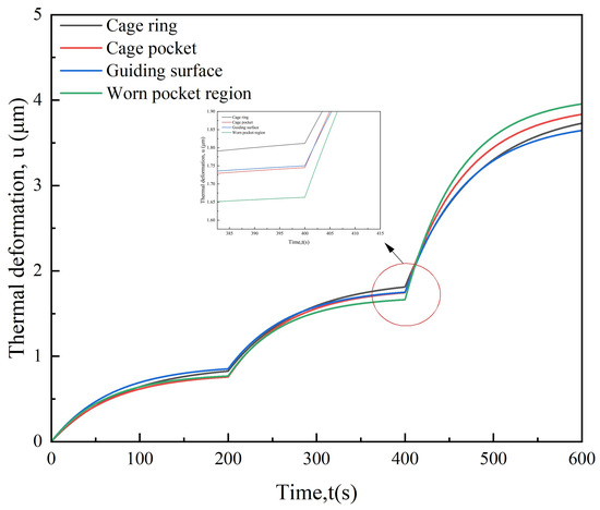
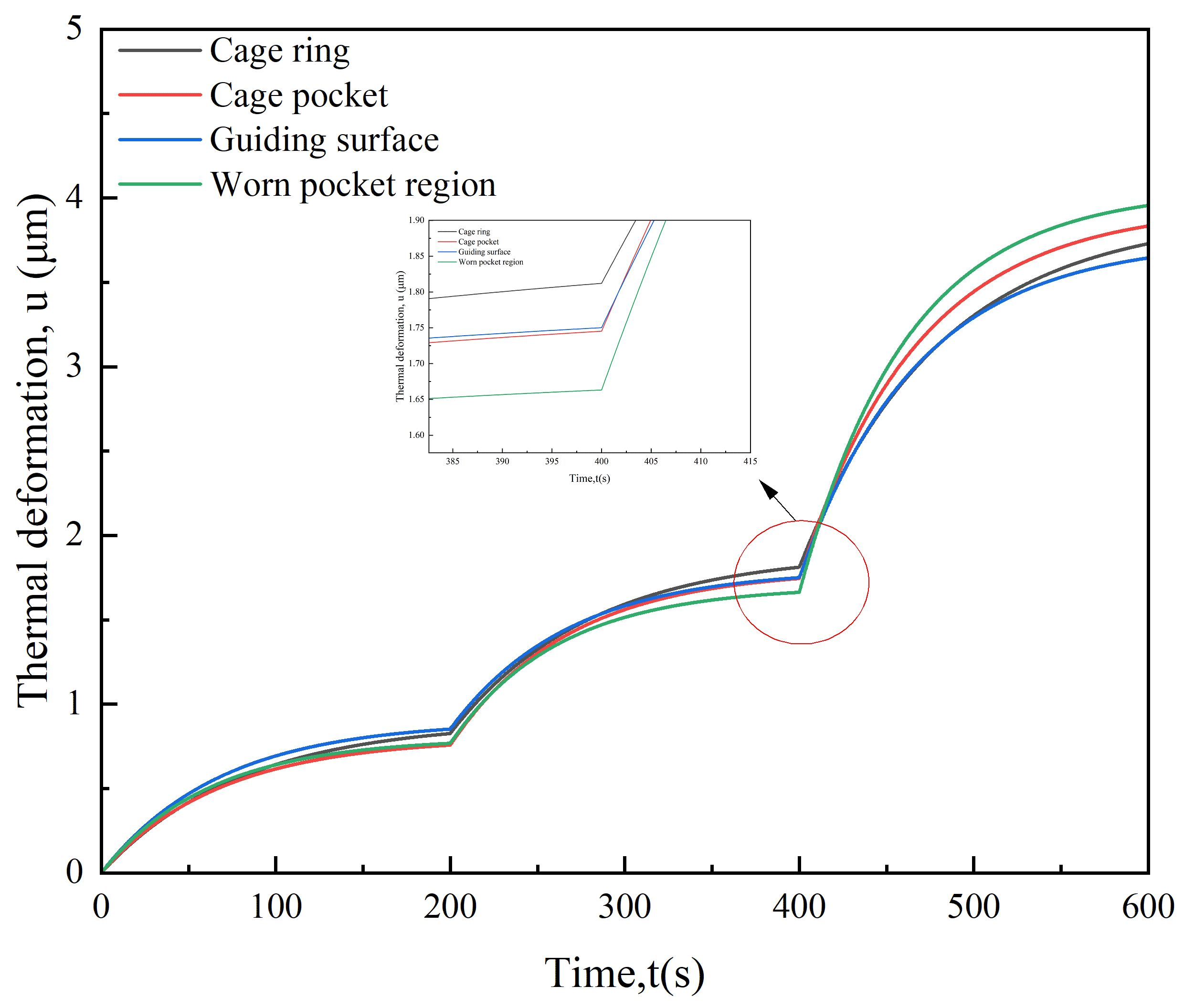
The ANSYS transient analysis provides the temperature field at each time step. The maximum temperature in each selected cage region is extracted as its representative value. Figure 5a presents the corresponding transient temperature responses. Figure 5b shows the steady-state regional temperatures at different rotational speeds. The temperature rises are substituted into Equation (5) to calculate the equivalent thermal deformations. The resulting transient deformation responses are presented in Figure 6.
Figure 6.
Predicted thermal deformation responses under stepwise rotational speeds.
As shown in Figure 6, the predicted thermal deformation increases after each speed change and gradually approaches a new steady-state level. A further increase is observed as the rotational speed rises from 6000 to 12,000 rpm and then to 20,000 rpm. Differences among the cage regions become more pronounced at higher rotational speeds. The inset highlights the transition near 400 s. These equivalent thermal deformations modify the local cage-pocket geometry and effective contact clearance and are subsequently introduced into the dynamic contact model through ΔδT.
3.2. Effect of Thermal Deformation–Cage Pocket Wear Coupling on System Dynamic States
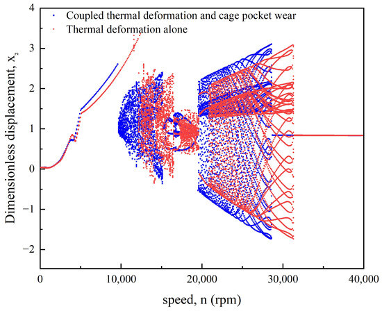
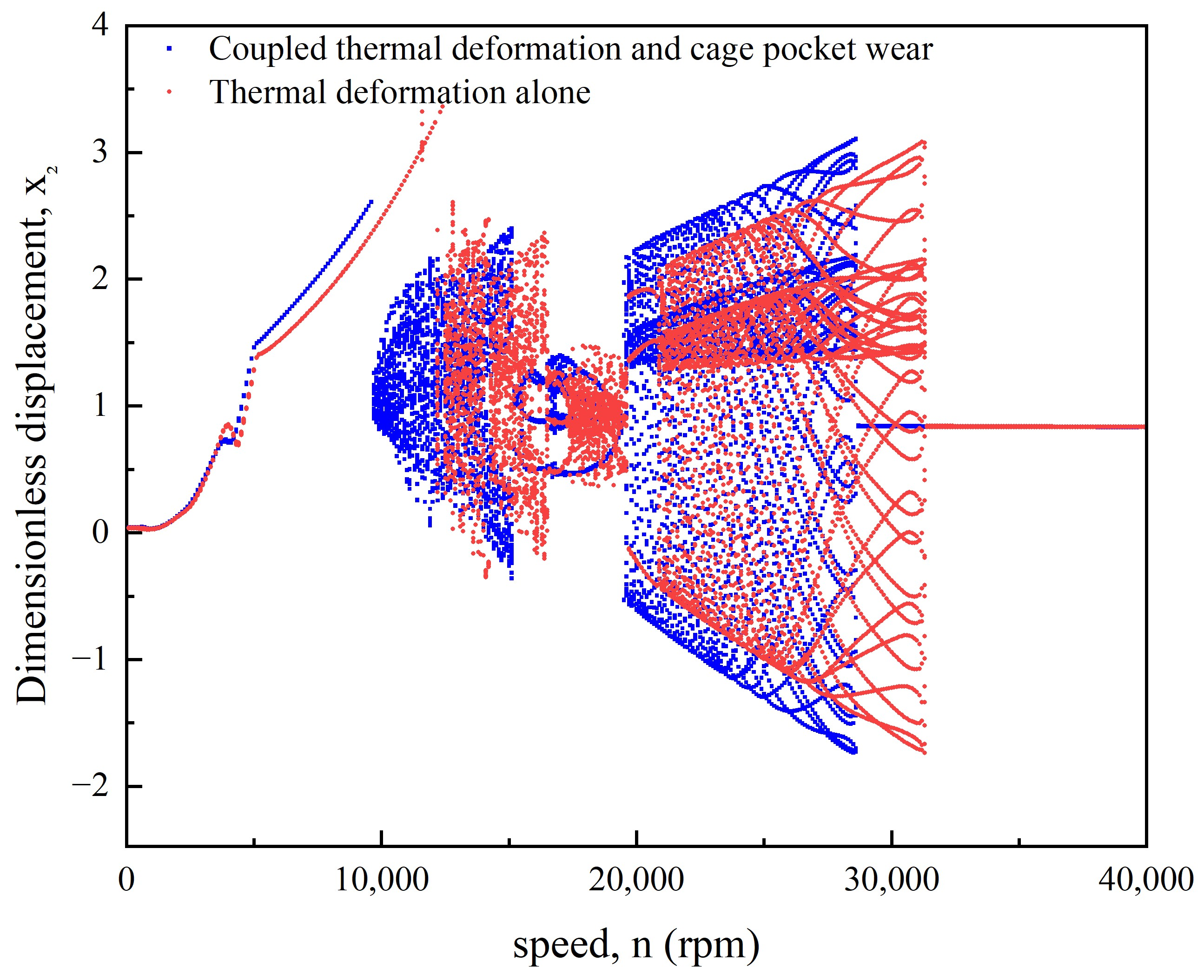
Bifurcation responses are calculated for the cases of thermal deformation alone and coupled thermal deformation–cage pocket wear. Rotational speed is used as the control parameter. Dimensionless displacement peaks in the x2 direction are extracted from the steady-state response, as shown in Figure 7.
Figure 7.
Comparison of system bifurcation characteristics under thermal deformation alone and coupled thermal deformation–cage pocket wear.
Below 9800 rpm, the bifurcation branches remain relatively close and are mainly single-valued. After cage pocket wear is introduced, multivalued branches appear near 9800 rpm. A similar transition occurs at 12,200 rpm when only thermal deformation is considered.
In the intermediate-speed range, both cases exhibit local periodic windows, but their branch positions and widths differ. Around 20,000 rpm, the thermal-deformation-only case exhibits a multi-period response, whereas the coupled case shows a chaotic response. At 28,600 rpm, the thermal-deformation-only case remains chaotic, while the coupled case begins to return to a single-period state. The thermal-deformation-only case does not return to a single-period state until 31,300 rpm. These results show that cage pocket wear changes the bifurcation path and alters the rotational-speed ranges of different states.
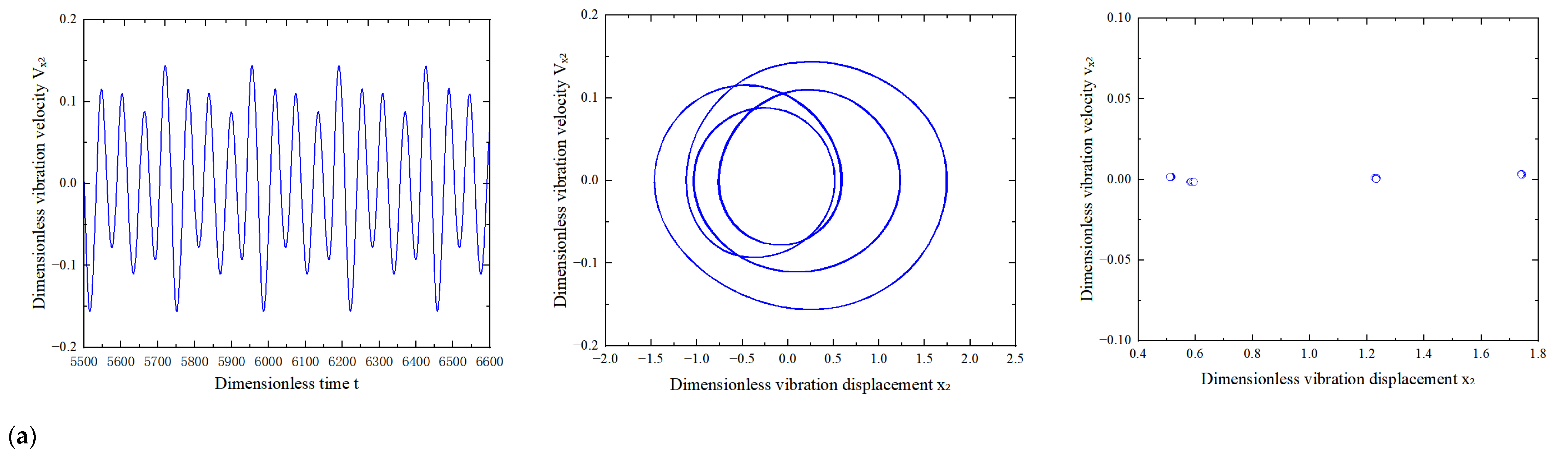
Figure 8 compares the time-domain responses, phase trajectories, and Poincaré sections under thermal deformation alone and the coupled effects of thermal deformation and cage pocket wear at 6000, 12,000, and 20,000 rpm.
Figure 8.
Time-domain responses, phase trajectories, and Poincaré sections under thermal deformation alone and coupled thermal deformation–cage pocket wear: (a) 6000 rpm; (b) 12,000 rpm; (c) 20,000 rpm.
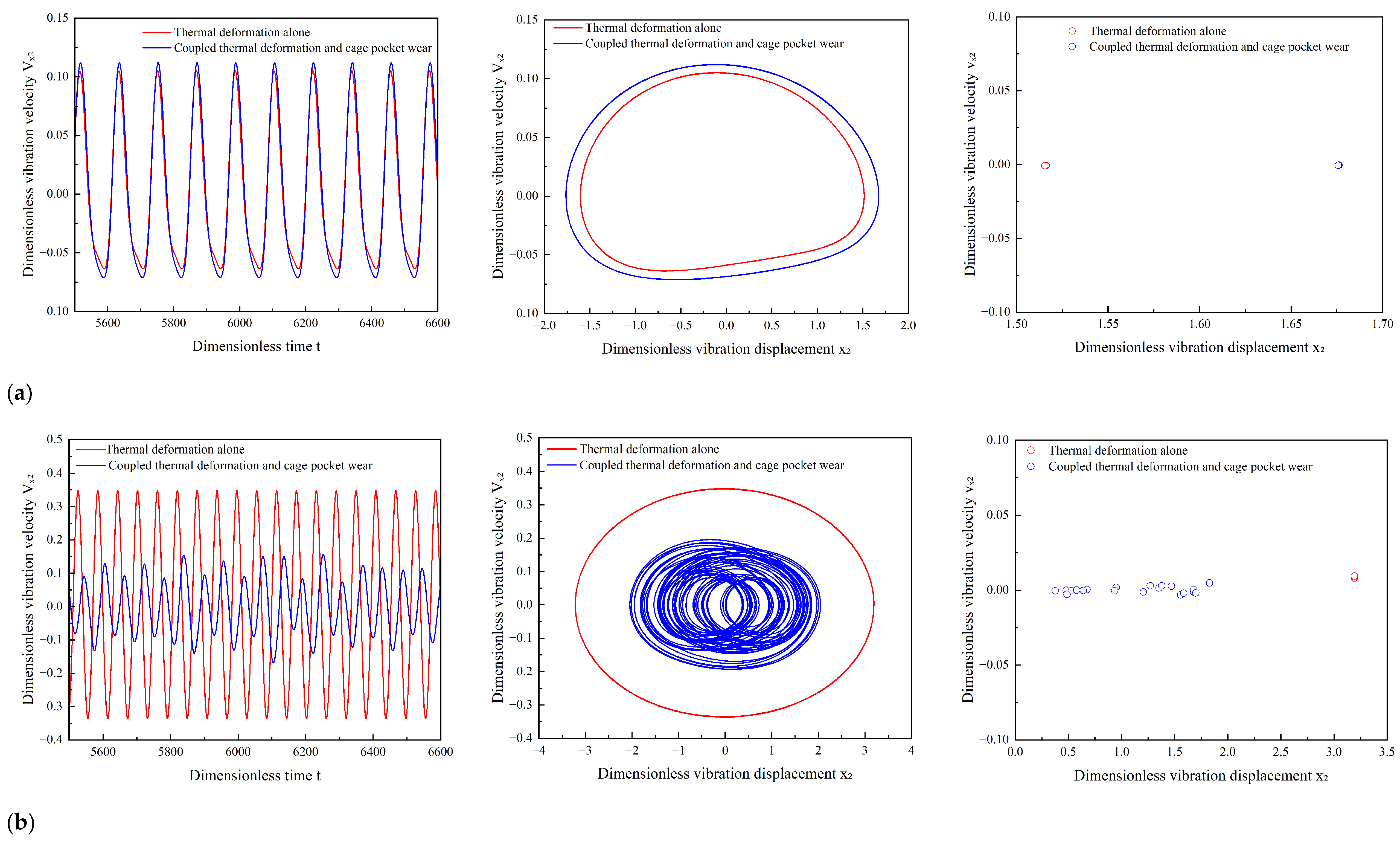
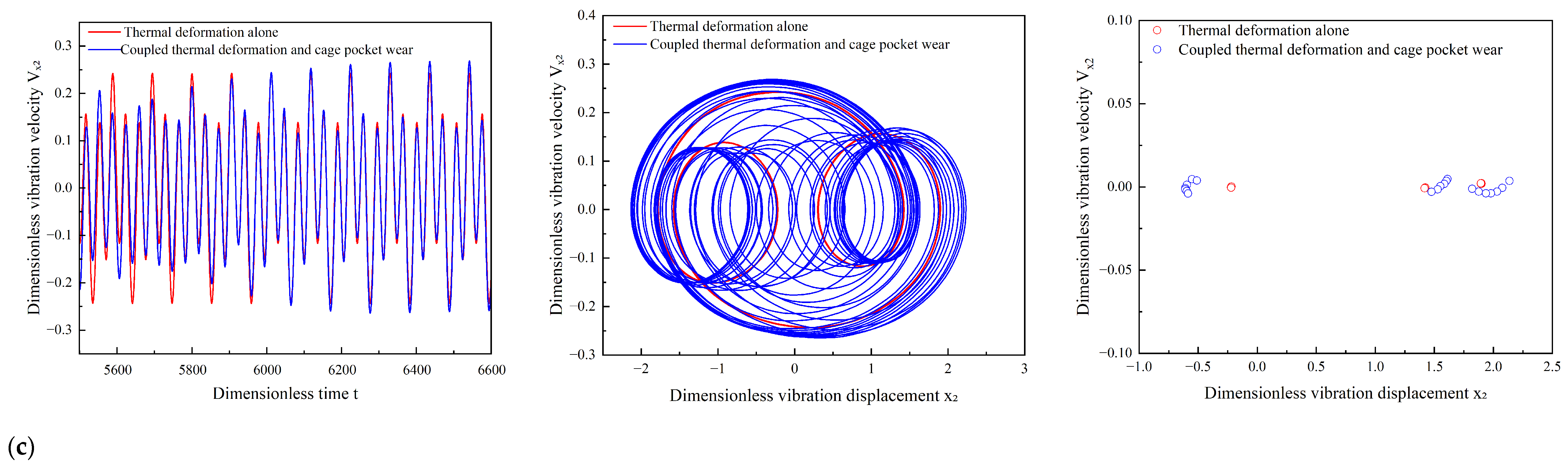
At 6000 rpm, both cases exhibit period-one motion. At 12,000 rpm, the thermal deformation-only case remains in period-one motion, while the coupled case exhibits a chaotic response. Its phase trajectory becomes more complex, with multiple discrete points appearing in the Poincaré section. This result is consistent with the bifurcation characteristics in Figure 7. At 20,000 rpm, the thermal-deformation-only case exhibits period-three motion, whereas the coupled case remains chaotic. These results show that cage pocket wear changes the dynamic state of the system at 12,000 and 20,000 rpm.
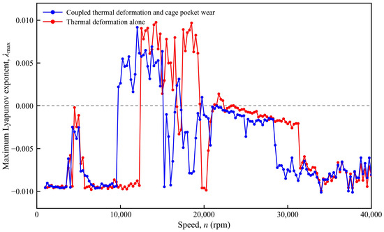
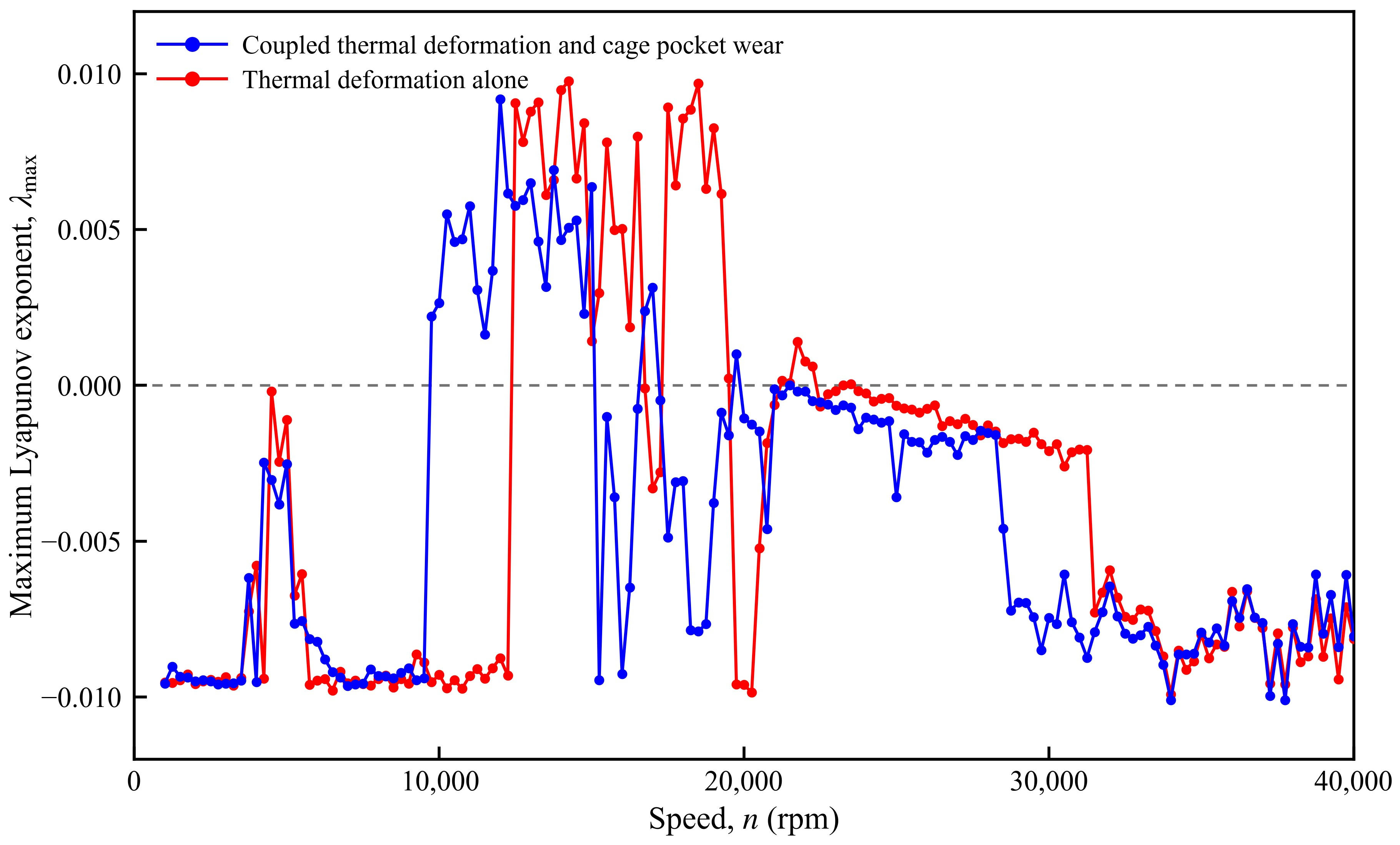
To further characterize the transition to chaotic dynamics quantitatively, the maximum Lyapunov exponent is calculated over the investigated rotational speed range, as shown in Figure 9. A positive maximum Lyapunov exponent indicates the divergence of neighboring trajectories. It therefore provides a quantitative criterion for identifying chaotic motion. The coupled model shows positive values over part of the intermediate speed range. The model with thermal deformation alone shows a different distribution. These results are consistent with the bifurcation characteristics shown in Figure 7.
Figure 9.
Maximum Lyapunov exponent versus rotational speed under thermal deformation alone and coupled thermal deformation–cage pocket wear.
3.3. Effect of Cage Pocket Wear Depth on the Nonlinear Response of the System
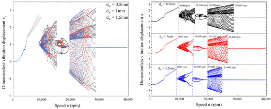
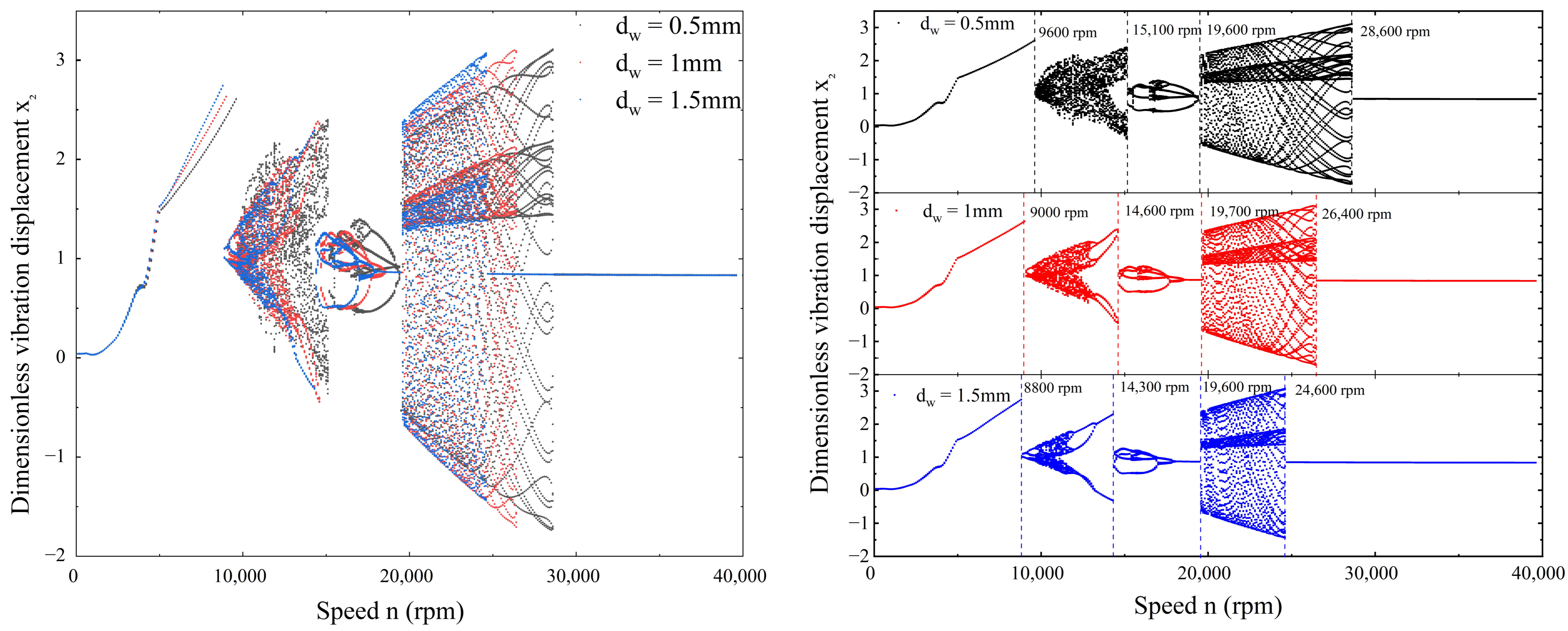
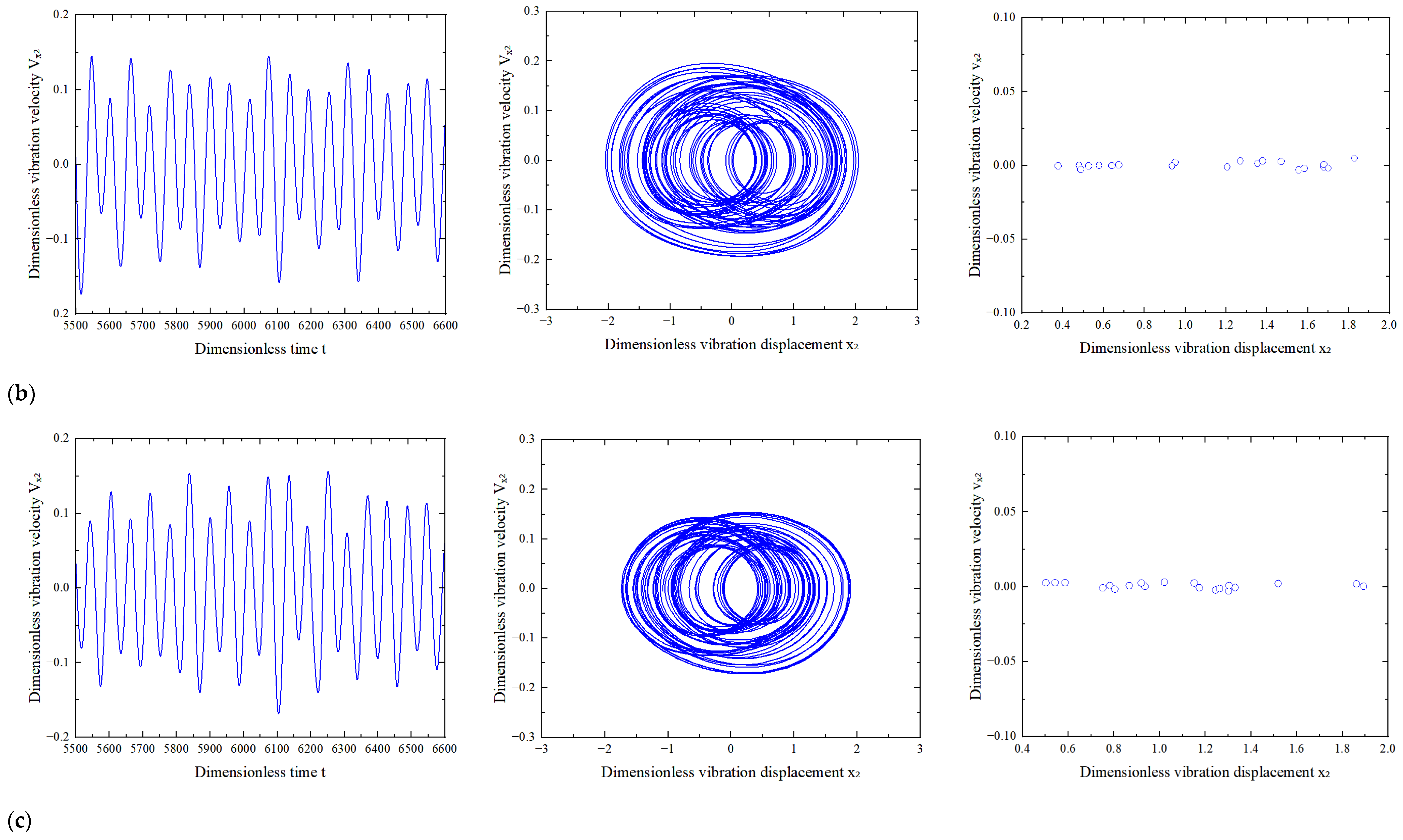
Since local additional clearance and stiffness degradation depend on wear depth, cage pocket wear depths of 0.5, 1.0, and 1.5 mm are considered while other parameters remain unchanged. The corresponding bifurcation responses are shown in Figure 10.
Figure 10.
Bifurcation characteristics of the system at different cage pocket wear depths.
At a wear depth of 0.5 mm, the system enters a chaotic state at 9600 rpm. A periodic window appears near 15,300 rpm, followed by a return to chaos at 19,000 rpm. The system returns to period-one motion at 28,600 rpm. For wear depths of 1.0 and 1.5 mm, chaotic responses begin at 9000 and 8500 rpm, respectively. Periodic windows appear near 14,600 and 14,300 rpm, while chaotic responses reappear at 19,700 and 19,600 rpm. For these two wear depths, the system returns to period-one motion at 26,400 and 24,600 rpm, respectively. These results show that increasing cage pocket wear depth changes the rotational-speed ranges of different dynamic states. The earlier transition to chaotic motion with increasing wear depth is mainly associated with the increased local clearance and reduced structural stiffness caused by cage pocket wear.
Figure 10 shows that 12,000 rpm lies within the complex-response range for all three wear-depth cases and occurs after the first dynamic-state transition in each case. Therefore, this speed provides a common operating condition for comparing the influence of different wear depths on the system response. The complete speed-dependent evolution of the dynamic states is evaluated using the bifurcation diagrams in Figure 10, while 12,000 rpm is selected only as a representative operating condition for detailed comparison of the time-domain responses, phase trajectories, Poincaré sections, and frequency-domain characteristics.
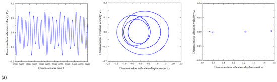
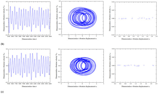
As sh own in Figure 11, increasing cage pocket wear depth from 0.5 to 1.5 mm at 12,000 rpm increases the peak dimensionless vibration velocity from 0.14 to 0.16. The vibration amplitude also increases. More discrete points appear in the Poincaré section, while the phase trajectory becomes more complex. These changes indicate a more complex nonlinear response with increasing cage pocket wear depth.
Figure 11.
Time-domain responses, phase trajectories, and Poincaré sections of the coupled thermal deformation–cage pocket wear system at different cage pocket wear depths: (a) 0.5 mm; (b) 1.0 mm; (c) 1.5 mm.
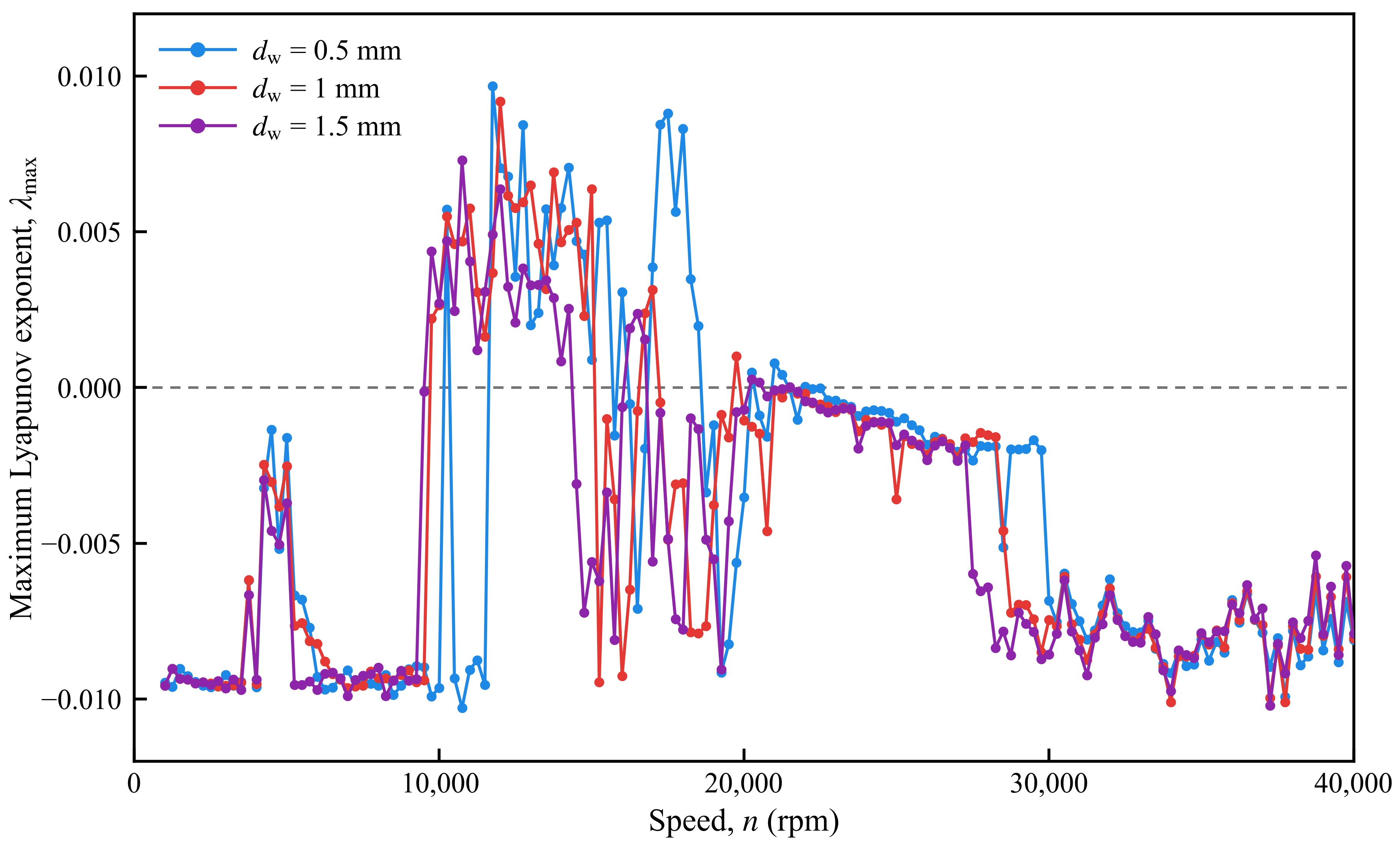
As shown in Figure 12, positive maximum Lyapunov exponents mainly occur within the intermediate speed range for all three cage pocket wear depths. This confirms the presence of chaotic responses in this region. The position and magnitude of the positive values vary with wear depth. This indicates that cage pocket wear affects the transition between different nonlinear dynamic states. The results are consistent with the bifurcation diagrams, phase trajectories, and Poincaré sections.
Figure 12.
Maximum Lyapunov exponent versus rotational speed for different cage pocket wear depths.
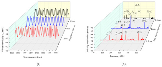
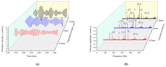
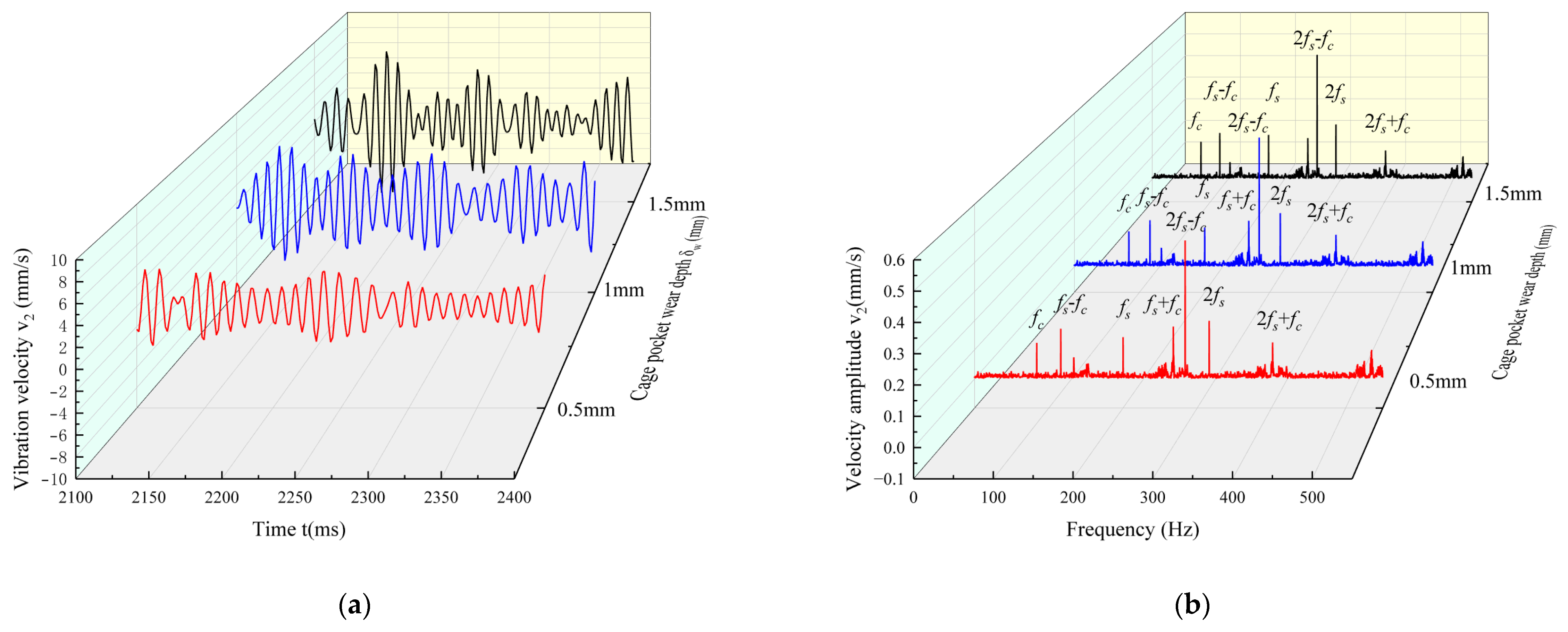
The steady-state responses at 12,000 rpm are analyzed to examine the effect of cage pocket wear on system vibration. The time-domain and frequency-domain results for wear depths of 0.5, 1.0, and 1.5 mm are shown in Figure 13.
Figure 13.
Time-domain and frequency-domain responses of the system at different cage pocket wear depths at 12,000 rpm: (a) time-domain response; (b) frequency-domain response.
As shown in Figure 13a, the vibration range increases as the wear depth increases from 0.5 to 1.5 mm. Local impact features also become more evident. These changes are associated with variations in ball–cage pocket contact caused by increasing wear depth.
Figure 13b shows the frequency-domain responses at different cage pocket wear depths. The spindle rotational frequency fs is 200.0 Hz, while the cage rotational frequency fc is 83.8 Hz. The combination frequencies fs − fc and fs + fc occur at 116.2 and 283.8 Hz, respectively. Components at 2fs − fc, 2fs, 2fs + fc are also observed at 316.2, 400.0, and 483.8 Hz, respectively.
As cage pocket wear increases, contact clearance increases and intermittent ball–cage pocket impacts become stronger. The amplitudes of spectral peaks near fs, fc and their combination frequencies also increase. Sideband components become more evident, suggesting a modulation effect of cage pocket wear on bearing vibration.
4. Experimental Validation
An angular contact ball bearing test platform is established to acquire vibration signals at different rotational speeds and cage pocket wear depths. The results are analyzed using time-domain responses, frequency spectra, and vibration amplitudes. Experimental results are compared with numerical results to evaluate the dynamic model.
Experimental Program
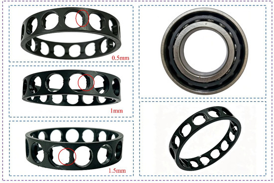
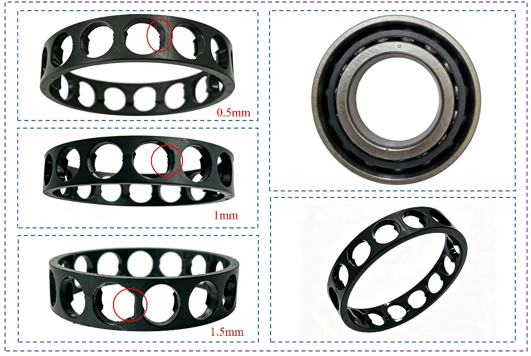
Figure 14 shows cage pockets with different preset defect depths. A 7006C angular contact ball bearing is used in the experiment. Local damage of the cage pocket is represented by preset machined defects with depths of 0.5, 1.0, and 1.5 mm. These defects reproduce the increase in pocket clearance caused by local material loss. They do not represent the complete process of natural wear. Changes in surface roughness, work hardening, material transfer, and lubricant film behavior are not considered in the present experiment. Therefore, the experimental validation is limited to the dynamic effects of local cage pocket damage under the investigated conditions. The 1.5 mm case represents a severe local defect. It is used to examine the dynamic response under an extended damage condition and is not intended to represent a typical depth of natural wear. Vibration signals of the rotor–bearing system are acquired at different rotational speeds, and the experimental results are compared with the numerical results to evaluate the established dynamic model.
Figure 14.
Experimental bearing and cages with preset cage-pocket defect depths.
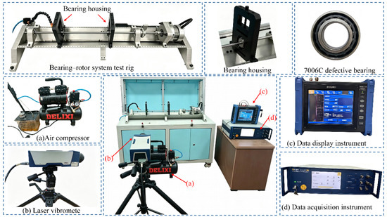
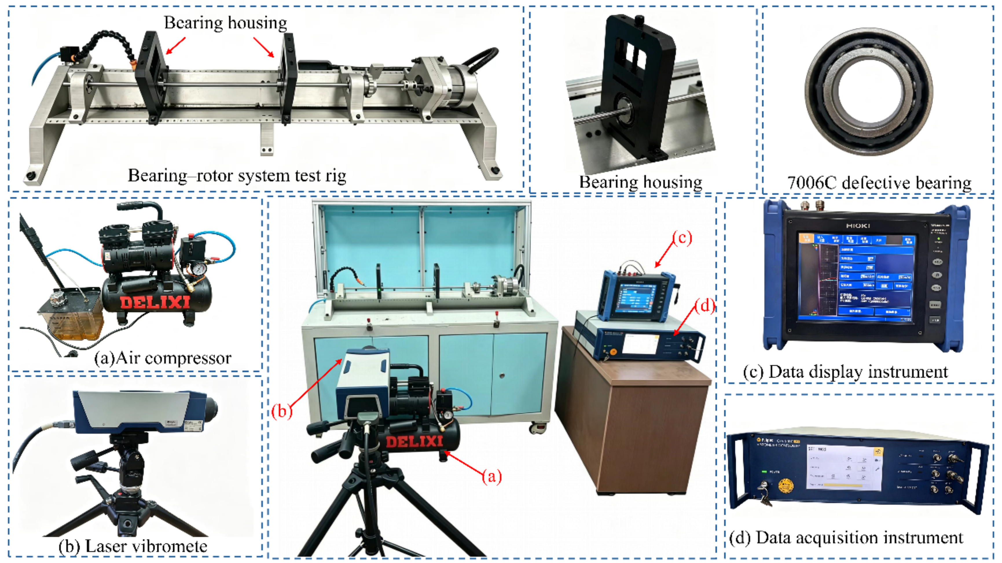
The rotor–bearing vibration test platform is shown in Figure 15. A Polytec OFV505 non-contact laser vibrometer measures the bearing-housing vibration velocity, as shown in Figure 15b. The HIOKI MR8847-01 instrument is used for synchronous signal acquisition, storage, and export, as shown in Figure 15d. The display instrument provides real-time monitoring, as shown in Figure 15c. The air compressor supplies compressed air for rotor operation and oil–air lubrication, as shown in Figure 15a.
Figure 15.
Vibration test platform of the rotor–bearing system.
The main specifications of the Polytec OFV505 laser vibrometer are listed in Table 3.
Table 3.
Main parameters of the Polytec OFV505 laser vibrometer.
Vibration experiments are conducted at different cage pocket wear depths to assess the established dynamic model. Experimental results are compared with numerical results in the time and frequency domains. Vibration amplitudes at different rotational speeds and response errors under representative operating conditions are also examined.
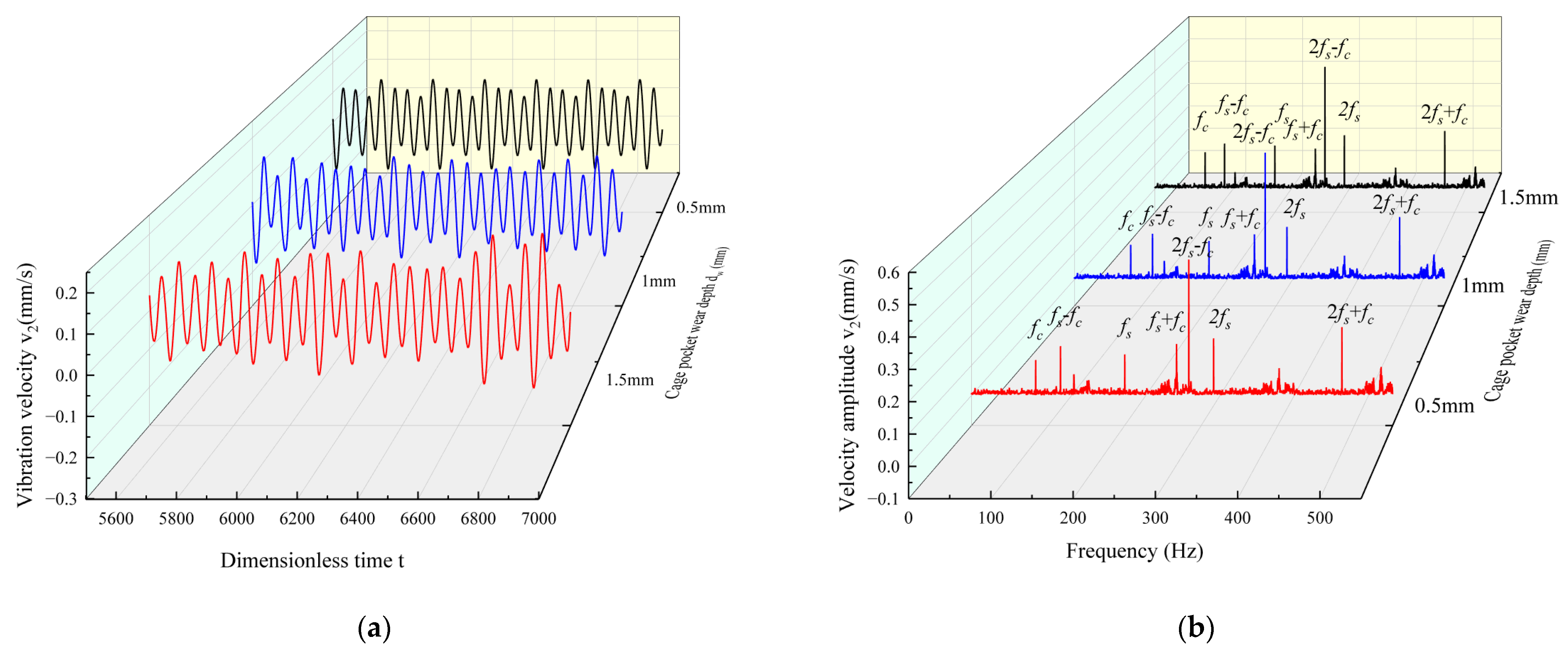
Figure 16a shows the time-domain vibration velocity responses at different cage pocket wear depths. The maximum vibration velocity is 3.661 mm/s at a wear depth of 0.5 mm. It increases to 6.365 and 8.863 mm/s at wear depths of 1.0 and 1.5 mm, respectively. This trend is associated with changes in contact clearance and ball–cage pocket impacts as wear increases.
Figure 16.
Experimental time-domain and frequency-domain vibration responses at different cage pocket wear depths at 12,000 rpm: (a) time-domain response; (b) frequency-domain response.
Figure 16b shows the frequency-domain responses at different cage pocket wear depths. At 12,000 rpm, the spindle rotational frequency fs is 200 Hz, while the cage rotational frequency fc is approximately 83.8 Hz. Combination components at fs − fc, fs + fc, 2fs − fc, 2fs and 2fs + fc are also observed. The spectral peak amplitudes at fs are 0.144, 0.154, and 0.194 mm/s for wear depths of 0.5, 1.0, and 1.5 mm, respectively. The amplitudes near fs, fc, and their combination frequencies generally increase with cage pocket wear depth. This trend indicates that the effect of cage pocket wear on the vibration response increases with wear depth.
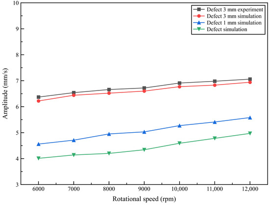
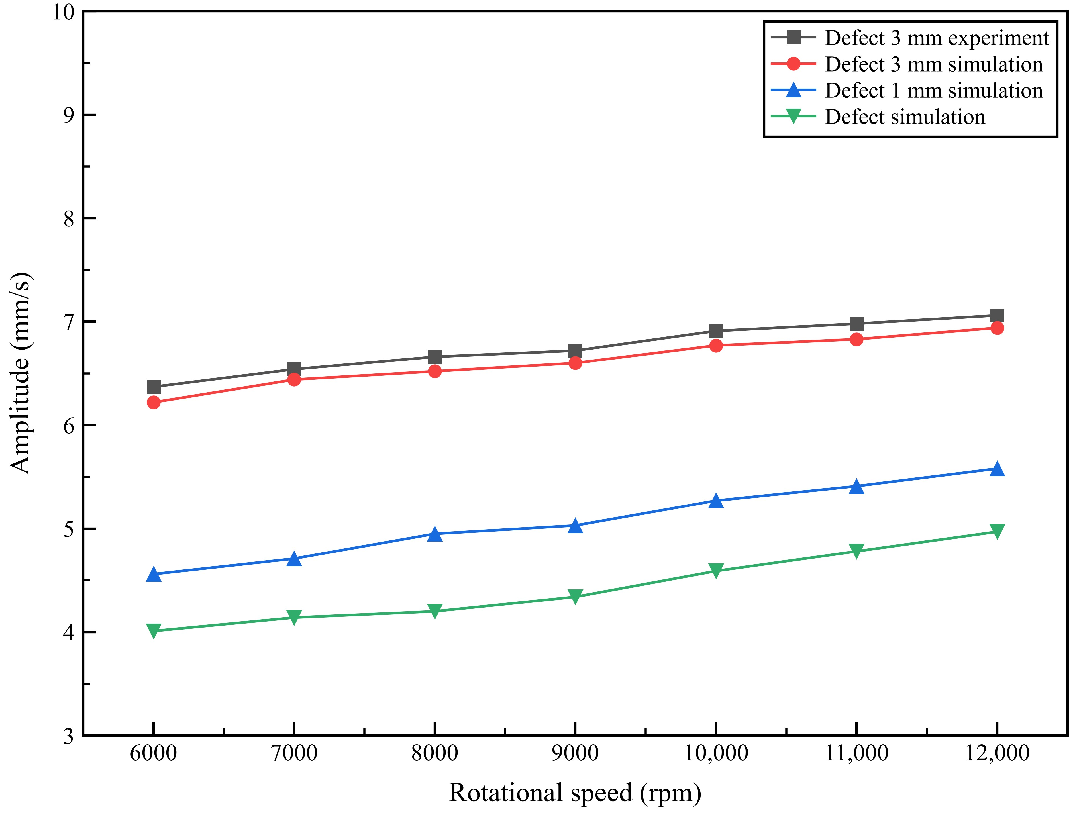
Vibration velocity amplitudes are extracted at different rotational speeds. The experimental results are compared with the numerical results in Figure 17.
Figure 17.
Comparison between experimental and numerical vibration amplitudes at different cage pocket wear depths and rotational speeds.
Figure 17 shows the variation in vibration amplitude with rotational speed for cage pocket wear depths of 0.5 and 1.5 mm. The vibration amplitude increases as rotational speed rises from 6000 to 12,000 rpm under both conditions. The 1.5 mm wear case consistently exhibits higher vibration amplitudes than the 0.5 mm wear case, indicating that increasing cage pocket wear increases the vibration response of the system.
To provide a quantitative validation of the proposed model over different cage pocket wear depths and rotational speeds, the characteristic vibration amplitudes at the cage rotational frequency fc and the upper sideband frequency fs + fc were extracted from both numerical and experimental results. The relative error between the numerical and experimental amplitudes is calculated as:
The corresponding results for wear depths of 0.5, 1.0, and 1.5 mm are summarized in Table 4, Table 5 and Table 6, respectively.
Table 4.
Comparison of numerical and experimental characteristic frequency amplitudes for a cage-pocket defect depth of 0.5 mm.
Table 5.
Comparison of numerical and experimental characteristic frequency amplitudes for a cage-pocket defect depth of 1.0 mm.
Table 6.
Comparison of numerical and experimental characteristic frequency amplitudes for a cage-pocket defect depth of 1.5 mm.
The mean relative errors for the fc amplitude are 4.56%, 4.60%, and 4.62% for wear depths of 0.5, 1.0, and 1.5 mm, respectively. For the fs + fc component, the corresponding mean relative errors are 4.42%, 4.70%, and 4.84%, respectively. These results indicate that the numerical model provides consistent predictions over the investigated rotational-speed range and wear depths.
For the 1.5 mm wear condition, the experimental and numerical results exhibit generally consistent trends. At 12,000 rpm, the experimental and numerical vibration amplitudes are 7.030 and 6.940 mm/s, respectively. The experimental amplitude is 1.30% higher than the numerical amplitude. The results indicate that the established model can effectively capture the vibration response characteristics of the system with cage pocket wear at different rotational speeds.
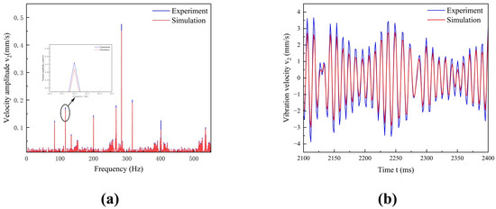
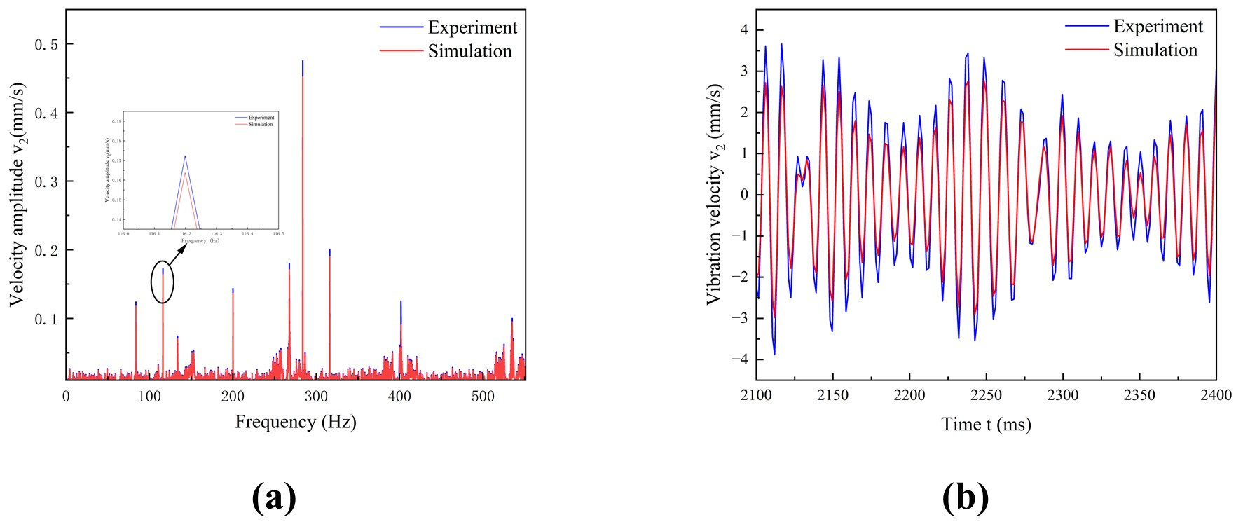
Experimental and numerical results for the 0.5 mm wear condition at 12,000 rpm are compared in Figure 18.
Figure 18.
Comparison of experimental and simulated vibration responses for a cage pocket wear depth of 0.5 mm at 12,000 rpm: (a) frequency-domain response; (b) time-domain response.
The experimental and numerical spectra show peaks near the cage rotational frequency fc, spindle rotational frequency fs, and their combination frequencies. The main characteristic frequencies occur at similar locations in both results. Here, fc is approximately 83.8 Hz and fs is approximately 200 Hz. Components at fs − fc, fs + fc, 2fs − fc, 2fs + fc are also observed. For the upper sideband fs + fc, the frequency is 283.8 Hz. The corresponding experimental and numerical peak amplitudes are 0.476 and 0.452 mm/s, respectively. The experimental value is 5.31% higher than the numerical value. Overall, the two results show close agreement in characteristic frequency locations and similar trends in spectral peak amplitudes. This comparison supports the frequency-domain response predicted by the model under cage pocket wear.
Figure 18b compares the experimental and numerical time-domain responses. The maximum vibration velocities are 3.661 and 2.844 mm/s for the experimental and numerical results, respectively. Although a noticeable difference remains in the peak amplitude, both responses exhibit similar periodic variation trends. The remaining amplitude discrepancy may be associated with uncertainties in assembly clearance, damping representation, structural vibration transmission, and the geometric idealization of the machined pocket defect in the numerical model. The comparison shows that the model reproduces the main time-domain vibration characteristics under cage pocket wear.
Three repeated experiments were performed under each investigated condition. The mean vibration amplitude was calculated as follows:
where xi denotes the vibration amplitude measured in the (i)th experiment. The 95% confidence interval was estimated using Student’s t-distribution with two degrees of freedom:
where s is the sample standard deviation of the three measurements. The critical value t0.975,2 is 4.303.
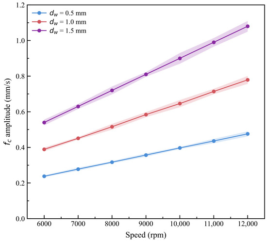
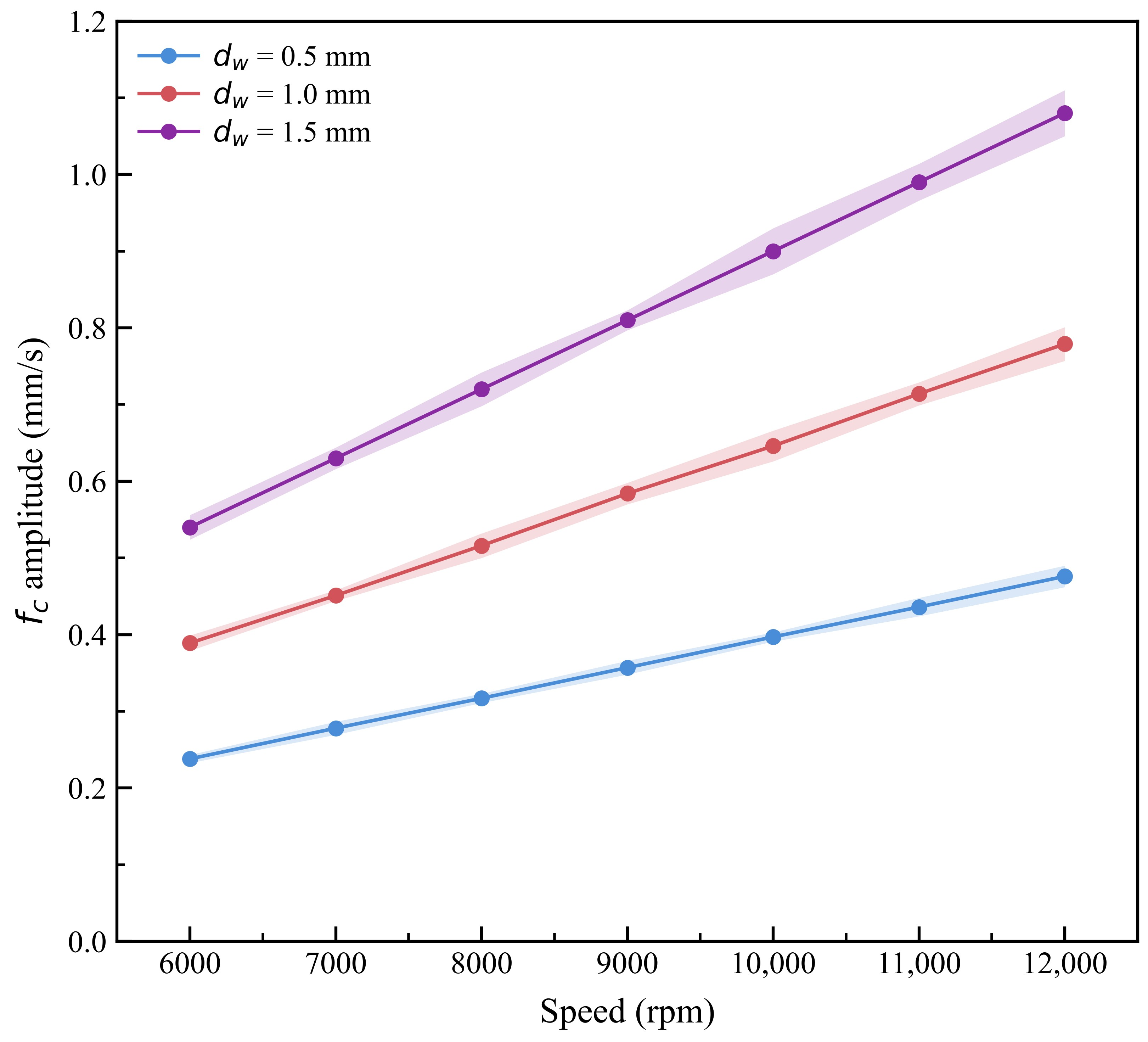
The mean vibration amplitudes and corresponding 95% confidence intervals are presented in Figure 19. Detailed numerical results are provided in Table 7. The confidence intervals remain relatively small over the investigated speed range. This indicates good repeatability of the experimental measurements.
Figure 19.
Experimental repeatability of fc amplitude under different wear depths.
Table 7.
Mean vibration amplitudes and 95% confidence intervals from three repeated experiments.
5. Conclusions
This study establishes a nonlinear dynamic model considering nonuniform cage thermal deformation and local cage pocket wear. Thermal deformation and wear-induced clearance are incorporated into the ball–cage pocket contact relationship. The vibration response and dynamic states are examined at different rotational speeds and discrete wear depths. Experimental results are further compared with numerical results. The main conclusions are as follows:
- The cage temperature field exhibits a nonuniform distribution, with the steady-state temperature ranging from 22 to 43.16 °C. Higher temperatures are mainly concentrated near cage pocket edges and adjacent cage regions, while the cage ring and guiding surface remain at lower temperatures. Thermal deformation shows a similar spatial distribution and increases with rotational speed. Nonuniform thermal expansion changes local cage pocket geometry, contact clearance, and ball–cage pocket contact deformation.
- Cage pocket wear changes the contact clearance and local stiffness, resulting in changes in system bifurcation paths and dynamic-state ranges. For wear depths of 0.5, 1.0, and 1.5 mm, chaotic responses begin at 9600, 9000, and 8500 rpm, respectively. The corresponding return to period-one motion occurs at 28,600, 26,400, and 24,600 rpm. At 12,000 rpm, the measured maximum vibration velocities are 3.661, 6.365, and 8.863 mm/s for wear depths of 0.5, 1.0, and 1.5 mm, respectively. These results show that cage pocket wear affects both vibration amplitude and nonlinear dynamic states of the rotor–bearing system.
- Cage pocket wear produces identifiable frequency components in the vibration spectrum. At 12,000 rpm, the spindle rotational frequency fs is 200 Hz and the cage rotational frequency fc is approximately 83.8 Hz. Components at fs − fc, fs + fc, 2fs − fc, 2fs, and 2fs + fc are also observed. Their spectral amplitudes and sideband components generally increase with wear depth. Experimental and numerical results show close agreement in the main characteristic frequency locations. For fs + fc, the experimental and numerical peak amplitudes are 0.476 and 0.452 mm/s, respectively, with a difference of 5.31%. These frequency components may serve as candidate vibration indicators for assessing localized cage-pocket damage under the investigated operating conditions. Their general applicability to naturally developed wear, different bearing configurations, lubrication conditions, and broader operating regimes requires further experimental validation.
Author Contributions
Conceptualization, data curation, and writing—original draft, C.Y.; funding acquisition, supervision, and writing—review and editing, S.Z.; funding acquisition, writing—review and editing, Z.W.; formal analysis, Q.H. and X.Z.; funding acquisition, software, Q.W. and X.Z.; methodology, H.X. All authors have read and agreed to the published version of the manuscript.
Funding
This research was funded by the National Natural Science Foundation of China, grant number 52205117; Scientific Research Innovation Capability Support Project for Young Faculty, grant number SRICSPYF-BS2025023; the Department of Science and Technology of Liaoning Province, grant numbers 2024-MSLH-401 and 2026JH2/101900002; the Project of Liaoning Provincial Education Department, grant number LJ212610153017; China Higher Education Society: 2024 Higher Education Scientific Research Planning Project, grant number 24RH0301.
Data Availability Statement
The data supporting the reported results cannot be shared due to privacy/ethical/commercial restrictions.
Conflicts of Interest
The authors declare no conflicts of interest.
References
- An, D.; Wei, Y.; Kumar, A.; Ma, S.; Shao, M.; Zheng, H.; Wang, Y.; Xu, P. Dynamic analysis of full-ceramic bearing-rotor system under thermally induced loosening in aerospace applications. Eng. Fail. Anal. 2024, 159, 108080. [Google Scholar] [CrossRef] [Scilit]
- Gu, J.; Zhang, Y.; Liu, H. Influences of wear on dynamic characteristics of angular contact ball bearings. Meccanica 2019, 54, 945–965. [Google Scholar] [CrossRef] [Scilit]
- Zhang, Y.; Zhang, S.; Zhou, G.; Zhang, J.; Qing, T.; Zhou, N. The friction and wear behaviors of polyimide bearing retainer under point-contact condition. Ind. Lubr. Tribol. 2020, 72, 931–936. [Google Scholar] [CrossRef] [Scilit]
- Misenar, J.L.; Arya, U.; Sadeghi, F. Cage Friction Measurements in High-Speed Bearings. Tribol. Trans. 2026, 69, 99–108. [Google Scholar] [CrossRef] [Scilit]
- Gao, S.; Han, Q.; Pennacchi, P.; Chatterton, S.; Chu, F. Dynamic, thermal, and vibrational analysis of ball bearings with over-skidding behavior. Friction 2023, 11, 580–601. [Google Scholar] [CrossRef] [Scilit]
- Gao, S.; Chatterton, S.; Pennacchi, P.; Han, Q.; Chu, F. Skidding and cage whirling of angular contact ball bearings: Kinematic-hertzian contact-thermal-elasto-hydrodynamic model with thermal expansion and experimental validation. Mech. Syst. Signal Process. 2022, 166, 108427. [Google Scholar] [CrossRef] [Scilit]
- Kim, D.; Kim, M.; Ryu, G.; Park, J. On heat, temperature, and cavity oil volume fraction of an under-race lubricated angular contact ball bearing. Tribol. Int. 2023, 187, 108715. [Google Scholar] [CrossRef] [Scilit]
- Han, Q.; Wen, B.; Wang, M.; Deng, S. Investigation of cage motions affected by its unbalance in a ball bearing. Proc. Inst. Mech. Eng. Part K J. Multi-Body Dyn. 2018, 232, 169–182. [Google Scholar] [CrossRef] [Scilit]
- Chen, H.; Liu, Y.; Liang, H.; Zhang, H.; Wang, W. The cage instability of angular contact ball bearing under high speed conditions. Mech. Mach. Theory 2024, 197, 105646. [Google Scholar] [CrossRef] [Scilit]
- Lee, Y.; Kwak, W.; Lee, Y. Failure mechanism of cryogenic self-lubricating ball bearings based on direct measurements of cage dynamics from run-to-failure tests. Eng. Fail. Anal. 2026, 197, 111164. [Google Scholar] [CrossRef] [Scilit]
- Harsha, S.P. Nonlinear dynamic analysis of rolling element bearings due to cage run-out and number of balls. J. Sound Vib. 2006, 289, 360–381. [Google Scholar] [CrossRef] [Scilit]
- Choe, B.; Kwak, W.; Jeon, D.; Lee, Y. Experimental study on dynamic behavior of ball bearing cage in cryogenic environments, Part II: Effects of cage mass imbalance. Mech. Syst. Signal Process. 2019, 116, 25–39. [Google Scholar] [CrossRef] [Scilit]
- Wang, H.; Li, Z.; Ji, X.; Wang, C.; Yang, L. Cage stability analysis of mixed-mounted double row angular contact ball bearing. Mech. Mach. Theory 2025, 211, 106035. [Google Scholar] [CrossRef] [Scilit]
- Kim, S.J. Micro-geometry deviation to reduce the cage slip of high-speed cylindrical roller bearings. J. Mech. Sci. Technol. 2023, 37, 595–605. [Google Scholar] [CrossRef] [Scilit]
- Dawoud, M.; Beitler, S.; Schwarze, H. Slip characteristics in cylindrical roller bearings—Part II: Influence of cage type on rolling element slip. J. Tribol. 2023, 145, 021204. [Google Scholar] [CrossRef] [Scilit]
- Kohar, R.; Hrček, S.; Smetanka, L.; Madaj, R.; Kozarik, D.; Mikusik, J. Co-simulation analysis of the bearing cage in the dynamic state. Results Eng. 2026, 29, 109697. [Google Scholar] [CrossRef] [Scilit]
- Yang, D.; Wang, X.; Hou, Y. Experimental and numerical studies on the roller–cage collision mechanism in a cylindrical roller bearing. Friction 2026, 14, 9441153. [Google Scholar] [CrossRef] [Scilit]
- Arya, U.; Sadeghi, F.; Conley, B.; Russell, T.; Peterson, W.; Meinel, A. Experimental investigation of cage dynamics and ball-cage contact forces in an angular contact ball bearing. Proc. Inst. Mech. Eng. Part J J. Eng. Tribol. 2022, 236, 2522–2534. [Google Scholar] [CrossRef] [Scilit]
- Denni, M.; Biboulet, N.; Abousleiman, V.; Lubrecht, A. Dynamic study of a roller bearing in a planetary application considering the hydrodynamic lubrication of the roller/cage contact. Tribol. Int. 2020, 149, 105696. [Google Scholar] [CrossRef] [Scilit]
- Yao, T.; Wang, L.; Liu, X.; Huang, Y. Multibody dynamics simulation of thin-walled four-point contact ball bearing with interactions of balls, ring raceways and crown-type cage. Multibody Syst. Dyn. 2020, 48, 337–372. [Google Scholar] [CrossRef] [Scilit]
- Yuan, D.; Wang, R.; Chen, S.; Chen, X. Experimental research on cage motion with different pocket shapes in angular contact ball bearing. Proc. Inst. Mech. Eng. Part J J. Eng. Tribol. 2022, 236, 1325–1335. [Google Scholar] [CrossRef] [Scilit]
- Schwarz, S.; Grillenberger, H.; Graf-Goller, O.; Bartz, M.; Tremmel, S.; Wartzack, S. Using machine learning methods for predicting cage performance criteria in an angular contact ball bearing. Lubricants 2022, 10, 25. [Google Scholar] [CrossRef] [Scilit]
- Zhang, S.; Song, B.; Wang, Z.; Bai, X.; Su, Z. Effects of cage pocket wear and thermal expansion on the nonlinear dynamics of ceramic bearings. J. Mech. Sci. Technol. 2026, 40, 61–72. [Google Scholar] [CrossRef] [Scilit]
- Krstić, V.; Milčić, D.; Madić, M.; Milčić, M.; Milovančević, M. Prediction of friction torque and temperature on axial angular contact ball bearings for threaded spindle using artificial neural network. J. Vib. Eng. Technol. 2022, 10, 1473–1480. [Google Scholar] [CrossRef] [Scilit]
- Wei, C.; Wu, W.; Hou, X.; Nelias, D.; Yuan, S. Research on mechanism of enhancing lubrication flow field regulation of high-speed bearing functional cage. Tribol. Int. 2023, 188, 108780. [Google Scholar] [CrossRef] [Scilit]
- Li, T.; Kolar, P.; Li, X.-Y.; Wu, J. Research development of preload technology on angular contact ball bearing of high speed spindle: A review. Int. J. Precis. Eng. Manuf. 2020, 21, 1163–1185. [Google Scholar] [CrossRef] [Scilit]
- Truong, D.S.; Kim, B.S.; Park, J.K. Thermally affected stiffness matrix of angular contact ball bearings in a high-speed spindle system. Adv. Mech. Eng. 2019, 11, 1687814019889753. [Google Scholar] [CrossRef] [Scilit]
- Truong, D.S.; Kim, B.S.; Ro, S.K. An analysis of a thermally affected high-speed spindle with angular contact ball bearings. Tribol. Int. 2021, 157, 106881. [Google Scholar] [CrossRef] [Scilit]
- Ambrożkiewicz, B.; Syta, A.; Gassner, A.; Georgiadis, A.; Litak, G.; Meier, N. The influence of the radial internal clearance on the dynamic response of self-aligning ball bearings. Mech. Syst. Signal Process. 2022, 171, 108954. [Google Scholar] [CrossRef] [Scilit]
- Ambrożkiewicz, B.; Syta, A.; Georgiadis, A.; Gassner, A.; Meier, N. Experimental verification of the impact of radial internal clearance on a bearing’s dynamics. Sensors 2022, 22, 6366. [Google Scholar] [CrossRef] [Scilit] [PubMed]
- Questa, H.; Mohammadpour, M.; Theodossiades, S.; Garner, C.P.; Bewsher, S.R.; Offner, G. Tribo-dynamic analysis of high-speed roller bearings for electrified vehicle powertrains. Tribol. Int. 2021, 154, 106675. [Google Scholar] [CrossRef] [Scilit]
- Aamer, S.; Sadeghi, F.; Meinel, A. Cylindrical roller bearing cage pocket lubrication. Tribol. Int. 2023, 188, 108851. [Google Scholar] [CrossRef] [Scilit]
- Hamrock, B.J.; Dowson, D. Isothermal Elastohydrodynamic Lubrication of Point Contacts: Part III—Fully Flooded Results. J. Lubr. Technol. 1977, 99, 264–275. [Google Scholar] [CrossRef] [Scilit]
- Fossier, C.; Touret, T.; Lefort, G.; Changenet, C. Thermal behavior in rolling bearing applications: Comparison of steel and ceramic materials applied to tapered rollers. Proc. Inst. Mech. Eng. Part J J. Eng. Tribol. 2023, 237, 1085–1097. [Google Scholar]

Disclaimer/Publisher’s Note: The statements, opinions and data contained in all publications are solely those of the individual author(s) and contributor(s) and not of MDPI and/or the editor(s). MDPI and/or the editor(s) disclaim responsibility for any injury to people or property resulting from any ideas, methods, instructions or products referred to in the content. |
© 2026 by the authors. Licensee MDPI, Basel, Switzerland. This article is an open access article distributed under the terms and conditions of the Creative Commons Attribution (CC BY) license.