


Abstract
The cavity expansion solution for loess is absent because the existing elastoplastic models fail to model the sophisticated behaviors of unsaturated loess as a classic axisymmetric boundary-value problem. This paper develops a novel solution for cavity expansion in unsaturated structural loess, taking the coupled hydro-mechanical and structural evolution into consideration. To properly model the behavior of the loess, the Barcelona Basic Model for unsaturated clay is modified by incorporating structural parameters of loess and a volumetric strain-dependent soil–water characteristic curve. The structural parameters are evolved with the degree of saturation and the plastic strain. Leveraging the hydro-mechanical coupling elastoplastic constitutive matrix of the modified constitutive model, the governing differential equations for cylindrical cavity expansion are derived by introducing an auxiliary variable to the stress equilibrium equation and the geometric equation which preserves the intrinsic radial symmetry during spatial coordinate mapping. By considering the constant water content condition, the problem considered is expressed as seven first-order differential equations with suction, three stress components, specific volume, and two structural parameters as unknowns. The governing equations are solved as an initial value problem by the Runge–Kutta scheme. After verifying the solution with well-established solutions and the numerical results from ABAQUS, parametric studies are conducted to investigate the effects of structure degradation and saturation on the expansion response. The results show that the proposed solution can capture the hydraulic yielding behavior well during cavity expansion and the effects of structure on the expansion responses. The proposed solution provides a more reasonable theoretical basis for modelling the static cone penetration test, pile installation effects and pressuremeter tests in loess.
1. Introduction
Loess is a typical aeolian unsaturated silty sediment characterized by high macroporosity, weakly cemented interparticle bonding (soil structure), and strong water sensitivity. In its natural unsaturated state, loess exhibits high shear strength due to matric suction and structural bonding; however, it is susceptible to severe structural breakdown and collapsible deformation upon wetting or shearing. Understanding the cavity expansion response in such structural soils requires explicitly accounting for both structural degradation and suction variations.
The cavity expansion theory provides significant theoretical basis for interpretation of the static cone penetration test, pile installation effect and pressuremeter test [1,2,3]. In geotechnical engineering, numerous practical problems can be conceptualized as cylindrical cavity expansion, such as the soil compaction effect induced by pile driving [4,5,6] and the cone penetration test (CPT) [7,8]. As a crucial theoretical approach for studying stress and displacement variations caused by the expansion or contraction of cylindrical cavities, the cavity expansion theory offers broad applicability in simulating various complex geotechnical engineering problems, and it has become one of the foundational theories in the field of soil and rock mechanics [9,10,11,12]. Fundamentally, cylindrical cavity expansion represents a classical axisymmetric boundary-value problem in continuum mechanics. By exploiting the intrinsic axial and radial symmetries of the geometry, stress fields, and displacement boundary conditions, complex three-dimensional continuum mechanics formulations can be simplified into mathematically tractable one-dimensional governing equations. However, the solution to cavity expansion in loess is currently not available, as the existing elastoplastic models are incapable of modelling the coupled hydro-mechanical and structural behaviors of the loess.
To date, researchers have derived various cavity expansion solutions for different soil types using diverse constitutive models [13,14,15,16,17]. Early studies predominantly adopted ideal elastoplastic models, which fail to reflect the variations in the mechanical state and behavior of soils during cylindrical cavity expansion. With the advancement of constitutive theories, Collins et al. (1994) [18]. incorporated critical state soil models into the cavity expansion theory, accounting for the state-dependent behavior of soils during expansion. Subsequently, based on the modified Cam-clay model, Collins et al. (1992) [19]. derived cylindrical cavity expansion solutions under drained and undrained conditions by utilizing the similarity of stress and strain paths around the cavity. Yu and Rowe (1999) [20] derived an elastoplastic solution for cavity contraction in tunnel excavation, systematically revealing the evolution laws of soil stress, displacement, and the plastic zone under unloading conditions, though neglecting the elastic deformation contribution within the plastic zone. Chen and Abousleiman (2013, 2016) [21,22] established a rigorous semi-analytical framework for cavity expansion and contraction under drained and undrained conditions based on the modified Cam-clay model and bounding surface plasticity theory. Considering natural soil anisotropy, Li et al. (2016) [23] derived an undrained semi-analytical solution for cylindrical cavity expansion using Dafalias’s anisotropic model (1987) [24], thoroughly analyzing the influences of initial and stress-induced anisotropy on the surrounding soil response where the initial axisymmetric stress field evolves due to directional fabric breakdown. Most aforementioned studies target saturated remolded soils. In practical engineering, however, most soils are unsaturated and structured, exhibiting more complex mechanical behavior than saturated soils. For unsaturated soils, Russell and Khalili (2006) [25] introduced a suction-dependent elastoplastic model to establish the first analytical framework for cylindrical cavity expansion considering matric suction but omitted the hydraulic yielding behavior during expansion. Chen et al. (2020) [26] developed an elastoplastic analytical model to systematically derive theoretical solutions under undrained and drained conditions. Zhai et al. (2021) [27] derived a semi-analytical solution considering suction effects based on the modified Cam-clay model and validated its reliability via pressuremeter tests. For structured soils, Mántaras and Schnaid (2002) [28], and Schnaid and Mántaras (2003) [29] first introduced structural characterization into cylindrical cavity expansion analysis, but their constitutive models were too simplified to describe structural evolution during expansion. Sivasithamparam and Castro (2020) [30] utilized the S-CLAY1S model to derive solutions in anisotropic structured soils. Subsequently, Li et al. (2017, 2021) [31,32] employed a simplified structural model to derive elastoplastic solutions under drained and undrained conditions, yet their solutions fail to degrade to the remolded state when the structure is fully destroyed. Thus, existing cavity expansion theories focus primarily on saturated remolded soils. Natural loess, however, is typically unsaturated and features pronounced water-sensitivity and structure. Although progress has been made separately in unsaturated or structured soil theories, a cavity expansion solution coupling the hydraulic properties and structural degradation of unsaturated loess has not yet been proposed, limiting its application to geotechnical problems in unsaturated structured loess. Although progress has been made separately in unsaturated or structured soil theories, a cavity expansion solution coupling the hydraulic properties and structural degradation of unsaturated loess has not yet been proposed, limiting its application to geotechnical problems in unsaturated structured loess. Specifically, existing formulations for unsaturated soils typically neglect the progressive degradation of structural bonds during deformation [25,26,27], whereas structural cavity expansion models are limited to saturated conditions and fail to capture suction variations under hydraulic constraints [28,29,30,31,32]. A unified theoretical framework capable of simultaneously capturing saturation-dependent structural breakdown, suction evolutions under closed hydraulic boundaries, and hydro-mechanical elastoplastic coupling during expansion remains unavailable.
This paper considers the hydro-mechanical coupling and structural features of unsaturated loess by incorporating a saturation-dependent structural parameter into the Barcelona Basic Model (BBM) to establish a hydro-mechanically coupled elastoplastic model. On this basis, the hydro-mechanically coupled elastoplastic constitutive matrix is derived for the cavity expansion problem under the rigorous constraint of rotational and axial symmetry. Combined with stress equilibrium and geometric equations, a set of governing partial differential equations for cavity expansion under constant water content are established by introducing auxiliary variables for transformation to preserve the radial mapping symmetry of governing equations and subsequently solved numerically using the Runge–Kutta method. The joint mechanisms of structural degradation and hydro-mechanical coupling on the expansion response are thoroughly investigated. The findings demonstrate how initial geometric and stress symmetries are maintained while local structural evolution takes place, providing a crucial theoretical foundation for analyzing and interpreting geotechnical engineering problems in loess sites, such as cone penetration tests, pile driving, and pressuremeter tests.
2. Problem Description and Basic Assumptions
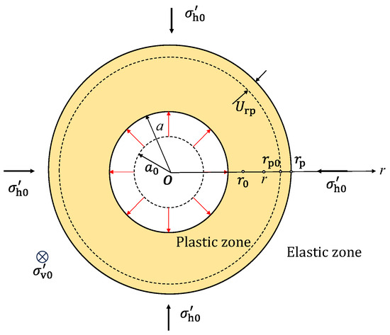
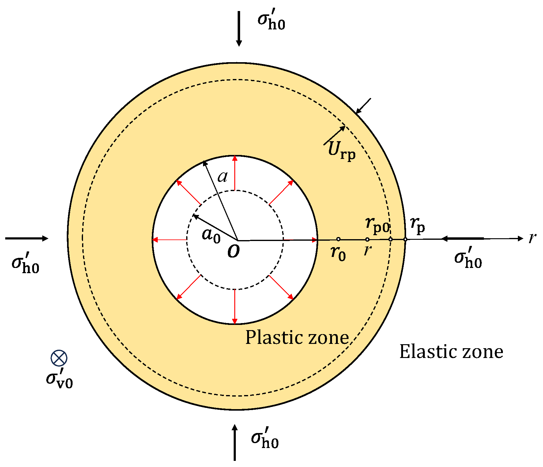
Figure 1 illustrates a schematic diagram of the cylindrical cavity expansion process in unsaturated soils. It is assumed that the initial radius of the cylindrical cavity is , and the surrounding horizontal and vertical stresses are and , respectively. As the internal pressure increases from to , the cavity radius gradually expands from to . Concurrently, a soil element at any given point around the cavity moves radially outward and is displaced to its current position . With the continuous increase in internal pressure, the soil at the cavity wall yields first, forming a plastic zone around the wall that is surrounded by an outer elastic zone. The radial position of the elastoplastic interface is denoted as , with its initial position being . The plastic and elastic zones span the ranges of and , respectively, and the radial displacement at the elastoplastic interface after expansion is represented by .
Figure 1.
Schematic diagram of cylindrical cavity expansion process in unsaturated soils.
As the fundamental cornerstone of the analytical framework established in this study, the fundamental assumption of axisymmetry governs the entire mathematical formulation. Under the strict constraint of axisymmetric geometry and boundary conditions, the physical field exhibits complete rotational symmetry around the vertical z-axis. Consequently, all state and field variables—including the stress tensor components (), strain components (), matric suction , and degree of saturation —are strictly independent of the circumferential angle and the axial coordinate , depending exclusively on the radial coordinate . This structural symmetry induces a significant dimension reduction, simplifying the complex two-dimensional (2D) continuum mechanics problem into a mathematically tractable one-dimensional (1D) system along the radial direction. Such a dimension reduction drastically reduces the mathematical complexity of the coupled governing differential equations. Furthermore, combining this radial symmetry with the self-similarity of stress and strain paths along the expansion boundary, the spatial deformation process can be mapped into a unified framework, allowing the governing field equations to be formulated as a standard initial value problem under the Lagrangian coordinate system.
It is assumed that the water content around the cavity remains unchanged during cavity expansion process. The constant water content assumption reflects a hydraulically closed or rapid-loading boundary condition where no overall moisture exchange occurs between the soil element and the external environment during expansion. This assumption is physically realistic for rapid geotechnical penetration or expansion operations (e.g., rapid cone penetration testing CPT or pressuremeter testing PMT) in unsaturated low-permeability loess, where pore-water flow is negligible over short timescales. Compared to the fully drained condition (constant suction ) and the fully undrained condition (zero total volumetric strain in saturated media), the constant water content condition bridges the response gap by allowing suction and degree of saturation to evolve continuously with volumetric deformation under a closed moisture constraint.
To obtain the elastoplastic solution for the cylindrical cavity expansion problem in unsaturated soils, the following basic assumptions are made:
- (1)
- The pore air pressure remains constant during the cavity expansion process and is equal to the atmospheric pressure ;
- (2)
- The cylindrical cavity extends infinitely along the axial direction, and the unsaturated soil is homogeneous and isotropic, meaning that prior to cavity expansion: ;
- (3)
- During the expansion process, the water content of the unsaturated soil remains constant, .
Unlike cavity expansion in saturated soils, the cylindrical cavity expansion in unsaturated soils under drained conditions involves hydro-mechanical coupling behavior, which is a unique feature of unsaturated soils. To fully simulate hydraulic behavior during the expansion process in unsaturated soils, in this study, the mechanical behavior is expressed by the mean effective stress tensor and strain tensor , whereas the hydraulic behavior is represented by suction and saturation . This study adopts the stress state variables and yield criterion established within the classical BBM framework [33]. Within this framework, the mean effective stress tensor can be expressed as:
where is the total stress tensor; is the pore air pressure, is the saturation of the loess, is the pore water pressure, is the matric suction, and is the Kronecker delta.
According to the geometric characteristics, a cylindrical coordinate system () is generally adopted to study the cylindrical cavity expansion problem, and its total stress and effective stress components can be expressed as , and , respectively. By virtue of the aforementioned rotational symmetry, all shear stress and shear strain components vanish identically. Throughout the entire process of cylindrical cavity expansion in unsaturated soils, any unit soil element in both the elastic and plastic regions satisfies the equilibrium equation:
3. Hydro-Mechanical Coupled Constitutive Model for Structured Loess
3.1. Structural Parameters of Unsaturated Loess
Due to the structural characteristics of loess, the yield stress and internal friction angle of undisturbed loess are both greater than those of remolded loess. Accounting for the interparticle bonding and dynamic destructuration of natural loess during plastic deformation, the yield surface and structural degradation relations are extended in [34,35]. To further account for the soil structure of loess, the yield stress structural parameter and the frictional strength structural parameter are introduced, expressing the yield stress and frictional strength of unsaturated structured loess as , respectively:
where is the effective yield stress in the saturated state; is the stress ratio at the critical state, is the internal friction angle of the intact soil.
Following the definition of structural parameters proposed by Taiebat et al. (2010) [34], and are defined as functions of the plastic damage strain , and their expressions are given as follows:
where and are the initial structural parameters. and are both parameters for the structural degradation rate; the structural degradation rate parameters and reflect the sensitivity of soil structural bond breakdown to plastic strain development and suction changes (wetting), respectively. Specifically, governs the rate of bonding collapse induced by plastic shear strain during shearing, whereas controls the structural degradation driven by wetting-induced debonding. In practical application, can be calibrated by fitting the stress–strain and volumetric strain curves from conventional triaxial shear tests on both intact and remolded loess specimens under the same suction level. On the other hand, is determined through isotropic compression or wetting-induced collapse tests under controlled suction states by evaluating the reduction rate of the virtual preconsolidation pressure upon wetting; is the void ratio; and are the compression and swelling parameters, respectively; is defined as a function of the plastic volumetric strain and the plastic deviatoric strain :
where is the soil property parameter, reflecting the degree of contribution of the soil plastic volumetric strain rate and plastic deviatoric strain rate to the plastic damage strain , and for convenience, the value of is generally taken as 0.5; is the incremental integration step size.
Changes in loess saturation significantly affect its cementation structure, which in turn influences the yield behavior and shear strength of the soil. To describe the evolution of loess structural characteristics with saturation and plastic strain, the influence of saturation is introduced into the structural parameters and . The structural parameters of loess can be further expressed as:
where and are both fitting parameters, representing the degree of influence of saturation on structural degradation.
3.2. LC Yield Equation
The classic BBM incorporates matric suction into the elastoplastic framework through the Loading–Collapse (LC) yield curve, defined by parameters including stiffness indices , critical state stress ratio , and preconsolidation pressure . To capture the specific mechanical behavior of unsaturated structural loess, the BBM is further extended in this study by introducing the structural parameters and . The structural bonds enlarge the initial yield surface and enhance shear strength. During plastic deformation and suction change, dynamic structural breakdown is governed by structural degradation rates and (Equations (5) and (6)), while the soil–water characteristic curve (SWCC) accounts for density-dependent water retention behavior under mechanical compression. Hence, based on the BBM [33], the yield equation of unsaturated loess in space can be expressed as:
where is the deviatoric stress; is the mean effective stress.
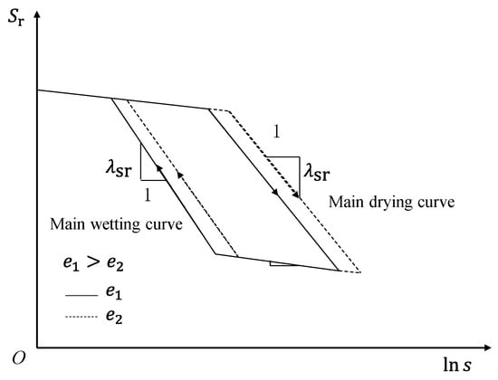
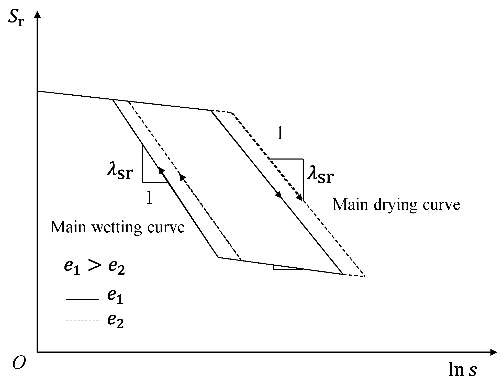
The soil–water characteristic curve (SWCC) proposed by Sun et al. (2008) [35], as shown in Figure 2, is adopted to describe the hydraulic behavior of unsaturated loess. This curve not only accounts for the effect of volumetric strain on the water-retention characteristics of the soil, but also conceptualizes the hydraulic behavior of unsaturated soils as an elastoplastic process, expressed as follows:
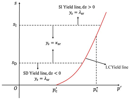
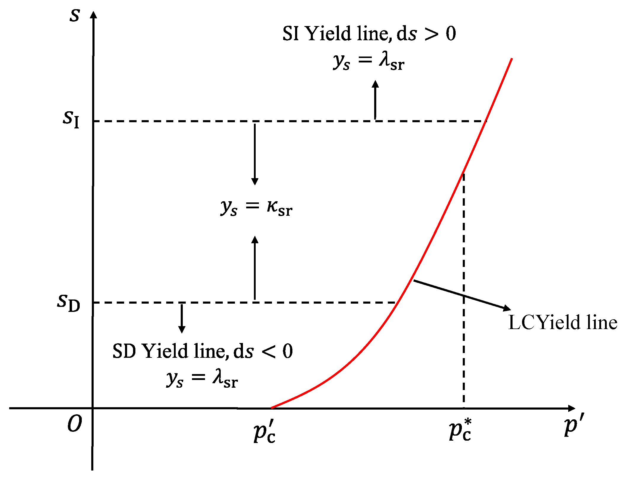
where is the slope of the relationship curve under constant suction conditions; and are the slopes of the main drying/wetting curve and the scanning curve of the soil–water characteristic curve, respectively. The value of varies under different hydraulic states; when , the hydraulic behavior is in an elastic state, where ; when with or with , hydraulic yielding occurs, where . Here, and represent the suction increase and suction decrease yield surfaces, respectively, corresponding to the intersection of the main drying curve with the scanning curve, and the intersection of the main wetting curve with the scanning curve. Notably, when the mechanical behavior enters an elastoplastic state, the hydraulic behavior may still remain elastic.
Figure 2.
Volumetric strain-dependent SWCC model [35].
As shown in Figure 2, the SWCC varies with the volumetric strain of the soil, through which the coupling between the mechanical and hydraulic behaviors of unsaturated loess is achieved. For unsaturated intact loess, the LC yield surface is jointly composed of the mechanical yield surface and the SWCC. Figure 3 illustrates the coupling relationship between the yield surface and the corresponding hydraulic yield lines of the SWCC in the plane.
Figure 3.
LC yield curves of unsaturated intact loess on plane.
4. Expansion Solution of Circular Cavity in Structural Loess
4.1. Analysis of Elastic Expansion Stage
According to Hooke’s law, the incremental stress–strain relationship in the elastic region can be expressed as:
where , , and are the increments of elastic strain components.
Combined with the equilibrium Equation (2), the effective stress components in the elastic region can be expressed as:
where is the mean effective stress; is the mean effective stress at the elastoplastic boundary, the calculation method of which will be determined later; is the displacement in the elastic region; , and are the initial suction, initial degree of saturation, and initial specific volume, respectively.
4.2. Analysis of Each Stage of Elastoplastic Expansion
When the plastic stage is reached, the total radial and tangential strain increments in the plastic region are composed of two parts: the elastic strain increments and the plastic strain increments, which can be expressed as:
where are the increments of plastic strain components.
In the plastic region, according to the associated flow rule, the plastic strain increments can be expressed by taking the partial derivatives of the yield functions:
where is the plastic multiplier, the detailed expression of which is given in Appendix A and:
Combining Equations (12) and (26), the governing equations for cylindrical cavity expansion in unsaturated loess can be obtained (the detailed derivation process is given in Appendix B):
Because the volumetric strain of the soil around the cavity varies along the radial direction, the equilibrium Equation (2) and the governing Equation (28) cannot be unified into a function of a single radial coordinate . This makes it difficult to directly couple and solve the equations simultaneously. Therefore, it is necessary to introduce an auxiliary variable to transform the governing equations into functions of a single variable. According to Chen and Abousleiman (2013) [21], who introduced the auxiliary variable 1 to indirectly represent the radial positions of state variables, the cylindrical cavity expansion problem can be formulated into a system of first-order ordinary differential equations (ODEs) with respect to . The auxiliary variable is defined as:
Differentiating Equation (29) yields:
According to Equation (29), the relationship between the radial coordinate and the auxiliary variable is:
where , which is the auxiliary variable at the cavity wall.
The three strain increments can be expressed in terms of the auxiliary variable as:
Under the condition of constant water content, is a constant; therefore, the increment of the degree of saturation can be expressed as:
Substituting Equation (35) into the equilibrium Equation (2) yields:
Substituting Equation (35) into Equation (12) yields:
Substituting Equations (32)–(35) into the constitutive matrix (28) yields:
Substituting Equations (30), (37) and (38)–(40) into Equation (36) and simplifying yields:
Substituting Equations (A20) and (33) into Equations (A5) and (A6) and simplifying yields:
Equations (37)–(43) reduce the cavity expansion problem in unsaturated loess to a system of seven partial differential governing equations based on the Lagrangian description. Here, serves as the sole independent variable, and the system contains seven unknown variables: three stress components (), two structural parameters (), specific volume (), and suction (). The system can be solved once the initial values of each unknown variable at the elastoplastic boundary are determined.
5. Numerical Solution Method
5.1. Initial Conditions
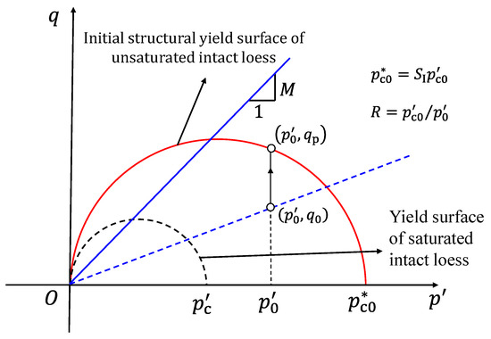
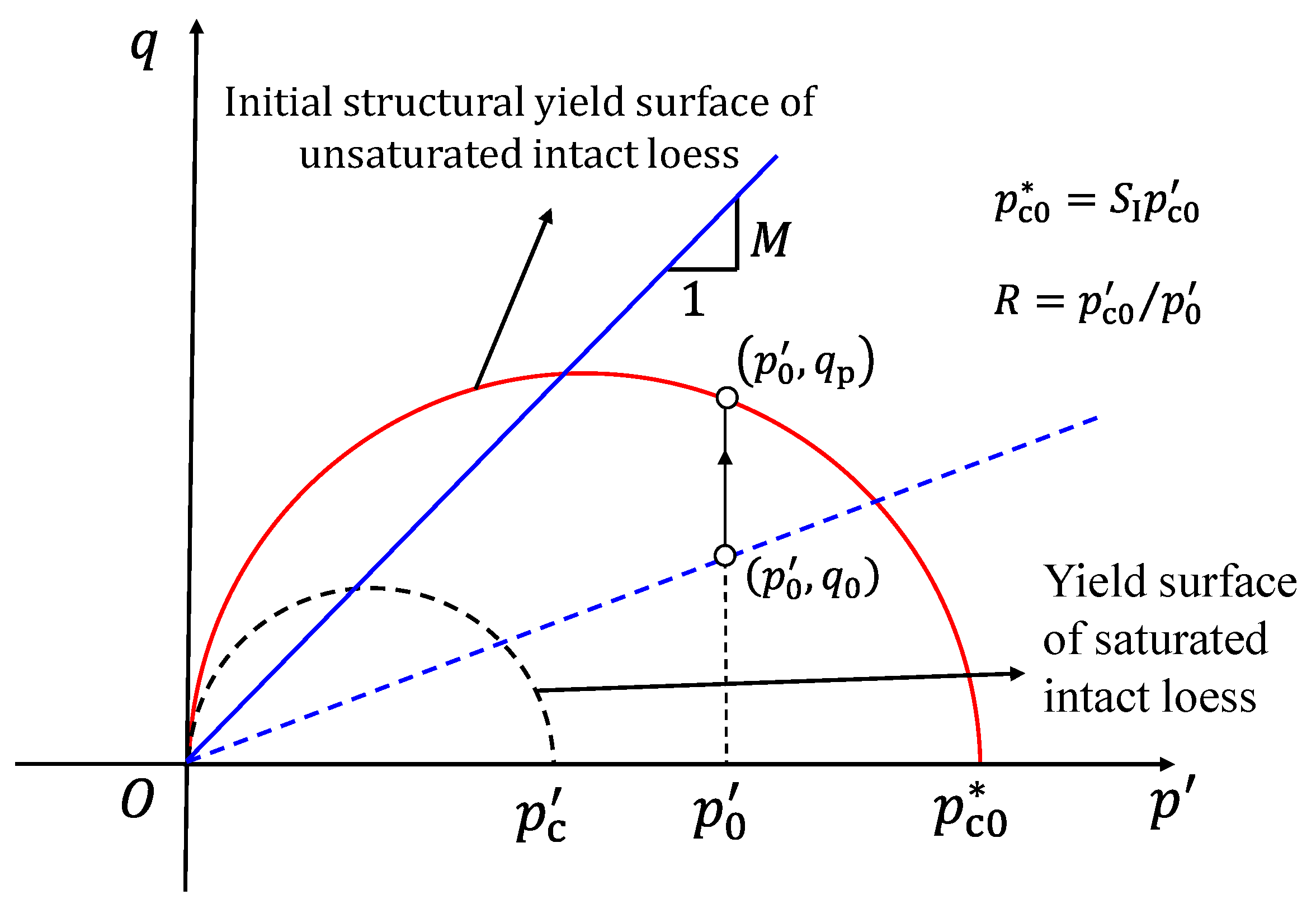
According to Equations (14)–(16), the mean effective stress remains constant during the elastic expansion stage; that is, the mean effective stress at the elastoplastic boundary equals its initial value . Its corresponding effective stress path is a vertical line in the plane, as shown in Figure 4. Furthermore, substituting into the yield Equation (11) yields the deviatoric stress at the elastoplastic interface :
where , is defined as the overconsolidation ratio.
Figure 4.
Projection of the LC yield surface on the plane.
According to the yield Equation (11) and Equations (14)–(16), the effective stress components at the elastoplastic boundary are:
Similarly, the specific volume and suction at the elastoplastic boundary can also be obtained based on the elastic solution and continuity conditions:
Based on , the auxiliary variable at the elastoplastic boundary is:
5.2. Case Study Validation: Large-Diameter Bored Piles in Bangkok
The formulation of the coupled hydro-mechanical cavity expansion in unsaturated loess ultimately culminates in a system of seven first-order ordinary differential equations (ODEs) based on the Lagrangian framework. It is worth emphasizing that this concise and elegant mathematical representation is made possible entirely through the fundamental axial symmetry and spatial self-similarity inherent in the boundary-value problem. Without leveraging these basic geometric and mechanical symmetries, reducing such a highly coupled multi-physical process—involving elastoplastic mechanical yielding, hydraulic suction evolution, and structural degradation—into a system of 1D ODEs would be mathematically intractable.
Specifically, the spatial axisymmetry eliminates two spatial dimensions (the axial coordinate and circumferential angle ), reducing the 3D strain and stress tensors into functions depending purely on the radial distance. Meanwhile, the stress-path similarity resulting from rotational symmetry allows a single Lagrangian spatial variable to track the complete deformation, stress, and hydraulic history of individual soil elements from the initial state to full plastic expansion. This transformation represents a direct and profound application of symmetry principles in theoretical geotechnical mechanics, demonstrating how physical symmetry simplifies complex non-linear constitutive integration.
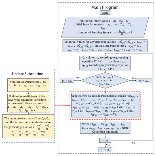
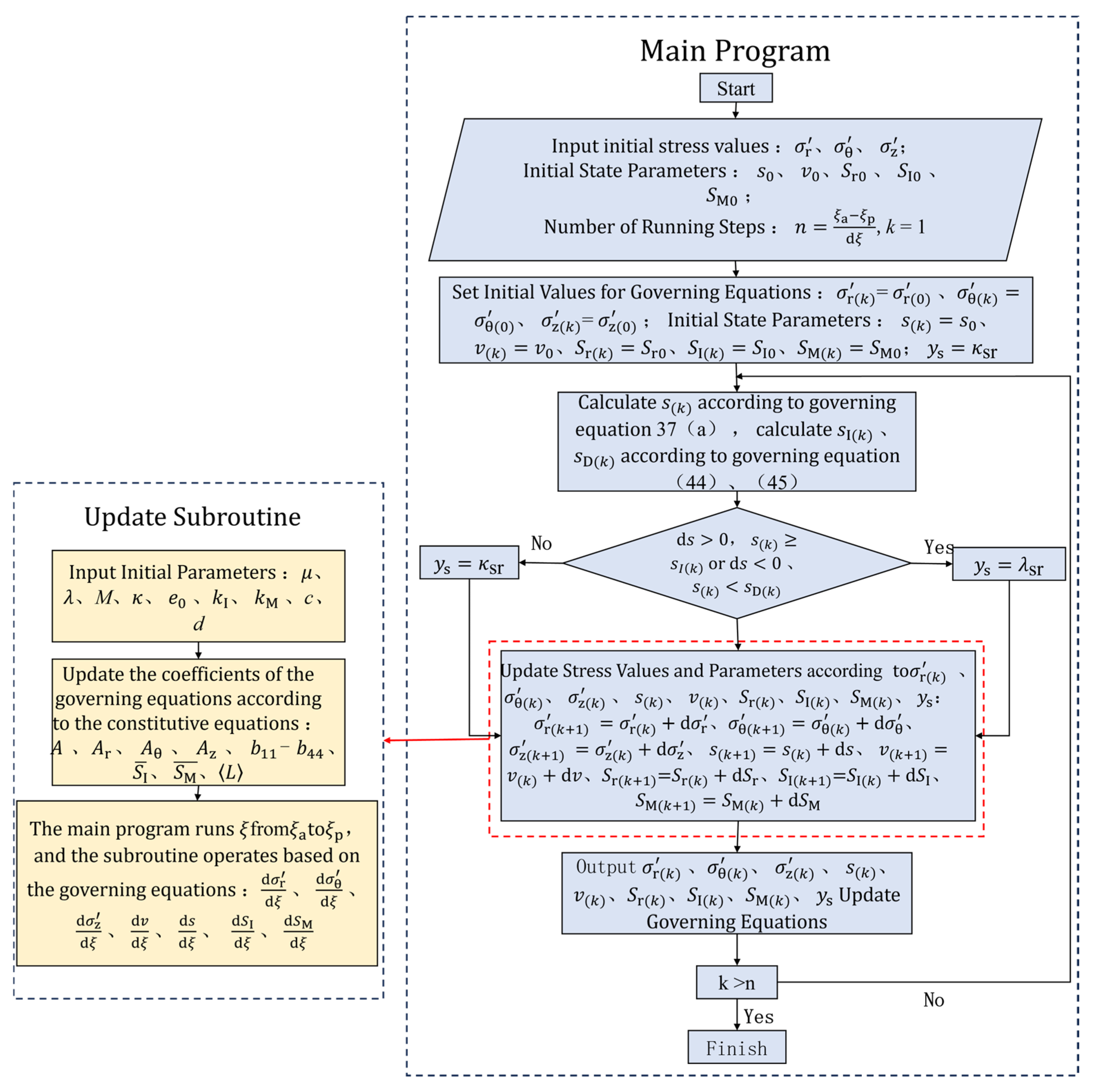
The partial differential governing equations for cavity expansion in saturated soils can be directly solved using ODE45, the built-in solver in MATLAB 2025b. However, unlike saturated soils, cavity expansion in unsaturated soils is closely linked not only to stress variations but also to hydraulic factors such as matric suction and degree of saturation evolution, involving both mechanical and hydraulic behaviors during the calculation process. In this study, both behaviors are conceptualized as elastoplastic processes, which generally do not yield simultaneously during loading; the mechanical behavior may yield while the hydraulic behavior remains elastic. Therefore, during numerical solution, it is necessary to dynamically determine whether the hydraulic state of the soil reaches yielding, but the built-in solver ODE45 in MATLAB lacks this capability. To address this, an iterative program based on the Runge–Kutta algorithm was developed in this study to solve the partial differential governing equations for cavity expansion in unsaturated loess through step-by-step integration while maintaining strict radial numerical symmetry across the computational grid. The specific flowchart of the computational program is illustrated in Figure 5 (with detailed procedures provided in Appendix C).
Figure 5.
Schematic diagram of calculation program for solving governing equations.
To execute the numerical integration of the transformed first-order ODE system, a classic fourth-order Runge–Kutta algorithm is implemented. The integration initiates from the elastic–plastic boundary, where the stress and state variables are rigorously defined by the elastoplastic boundary conditions and integrates inward step-by-step toward the cavity wall. To strike a balance between computational accuracy and convergence stability, an adaptive non-dimensional integration step size of is adopted. The iterative integration terminates upon reaching the cavity boundary (), subject to a stress residual convergence tolerance set to .
Since the soil–water characteristic curve (SWCC) is closely related to the specific volume of unsaturated soils, the values of and vary dynamically with the specific volume during cavity expansion. Based on Equation (12), the values of and can be dynamically updated via the following equation [36]:
where and are the initial values of the suction increase yield stress and the suction decrease yield stress of the unsaturated soil, respectively.
6. Verification and Analysis
6.1. Comparison and Verification of Existing Solutions
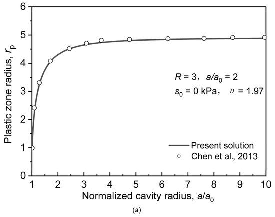
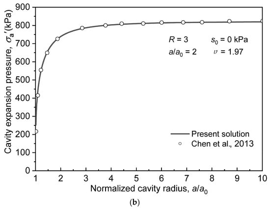
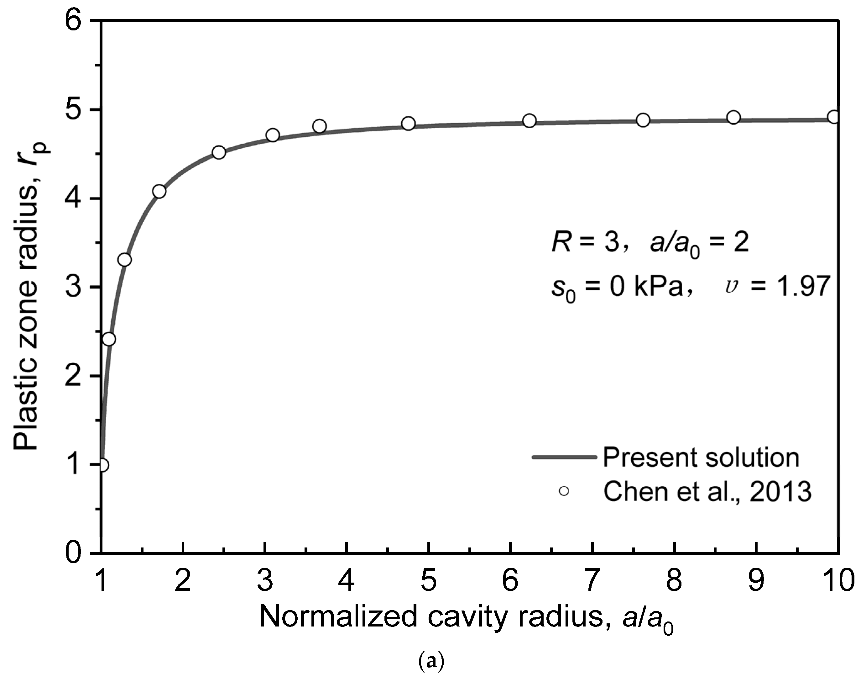
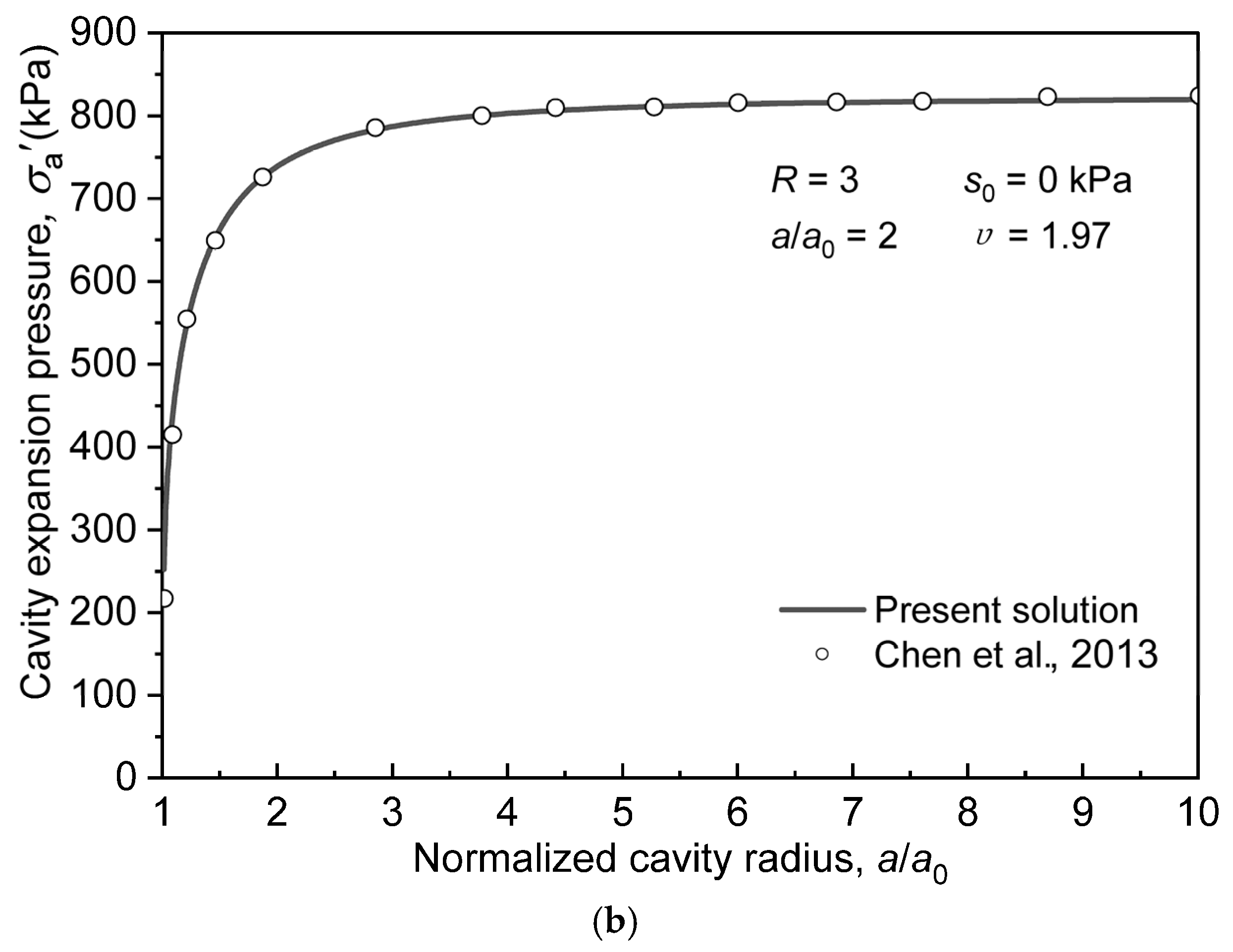
To verify the correctness of the proposed solution, it is first degenerated into a drained cavity expansion solution for unstructured saturated soil and compared with the solution developed by Chen and Abousleiman (2013) [21]. When suction decreases to zero, the soil becomes saturated. By simultaneously setting c = d = 0, = = 0, = = 1, the proposed solution degrades to the drained cavity expansion solution for unstructured saturated soils. The parameter values are adopted from Reference [21] .
Figure 6 presents the comparison of the normalized cavity expansion pressure and the elastoplastic radius variations with the normalized cavity radius. is the cavity expansion pressure; is the current expanded cavity radius; is the elastoplastic boundary radius; is the initial matric suction and compressive stress is defined as positive. As shown in the figure, the degenerated solution derived in this study is in excellent agreement with that from [21], validating the correctness of the proposed solution. Additionally, both the cavity expansion pressure and the elastoplastic boundary radius increase with the cavity radius ratio. At the initial stage of expansion, the cavity pressure changes rapidly because the soil surrounding the cavity wall swiftly enters a plastic state. As the plastic zone expands, the soil deformation gradually stabilizes, and the cavity expansion pressure approaches a steady state, exhibiting a trend of “initial drastic variation followed by stabilization.”
Figure 6.
Comparison between the degenerated solution of this study and the solution of Chen et al. [21]: (a) variations of cavity expansion pressure with normalized cavity radius (); (b) variations of normalized elastoplastic boundary radius with normalized cavity radius ().
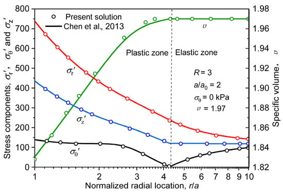
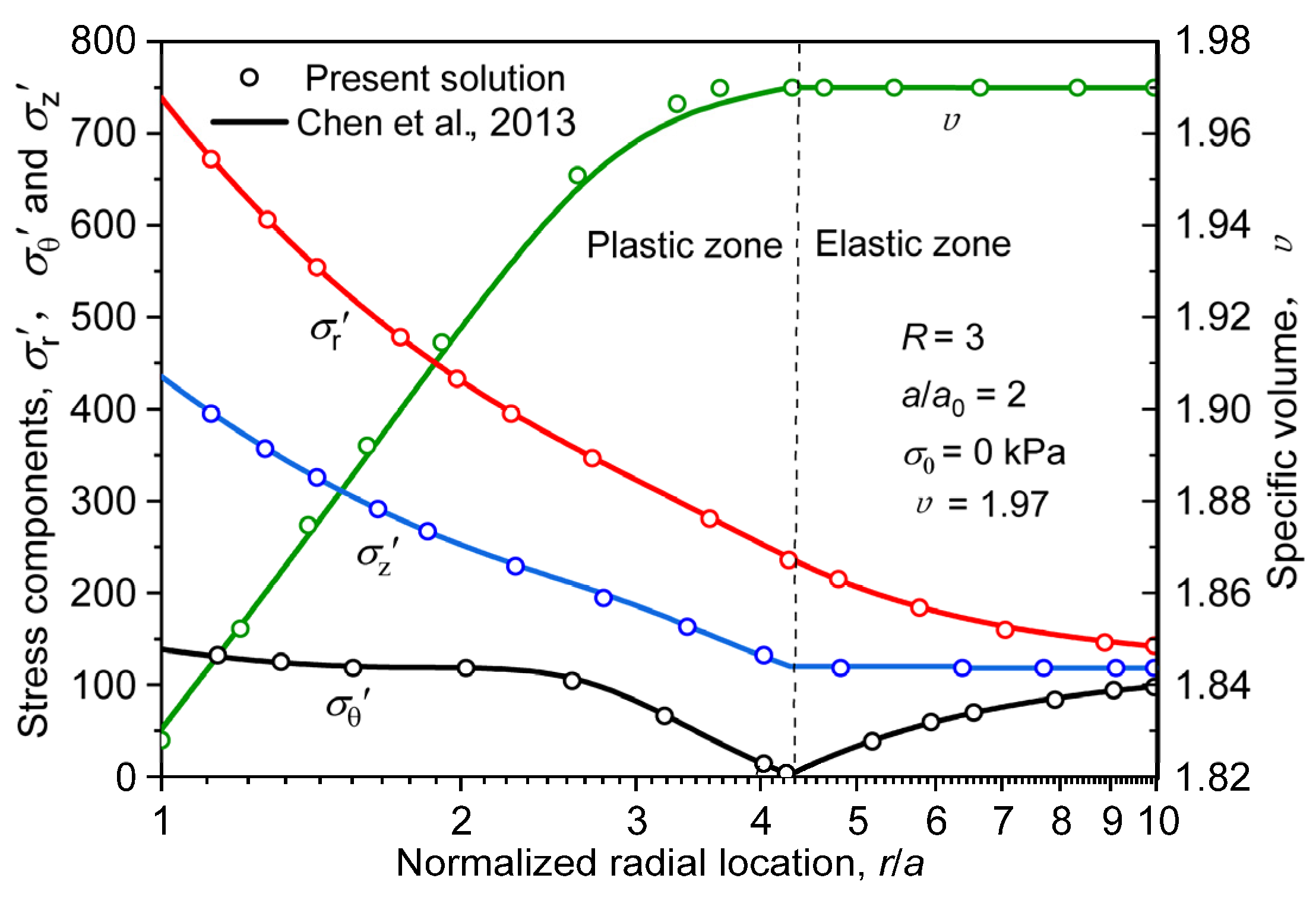
Figure 7 presents a comparison of the soil stress and specific volume variations around the cavity with radial position. In the figure, denotes the radial stress; is the circumferential effective stress; is the axial effective stress; is the specific volume (, where is the void ratio); is the radial distance from the cavity center; is the initial mean effective stress used for normalization. Compressive stress is defined as positive. It can be observed that the calculation results of this study are in good agreement with those from [21]. Concurrently, because the soil surrounding the cavity wall experiences the maximum compression during the expansion process while the regions farther away are less disturbed, reaches its maximum value at the cavity wall and gradually decreases along the radial direction. The variation trend of is similar to that of , decreasing along the radial direction, whereas first decreases and then increases along the radial direction. The specific volume reaches its minimum at the cavity wall, indicating that the soil experiences the maximum compression at this location.
Figure 7.
Comparison between the degenerated solution of this study and the solution of Chen et al. [21]: distributions and variations of stress components () and specific volume () around the cavity wall with normalized radial distance ().
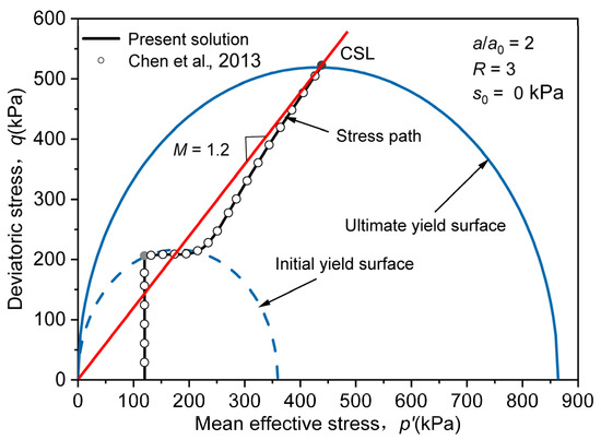
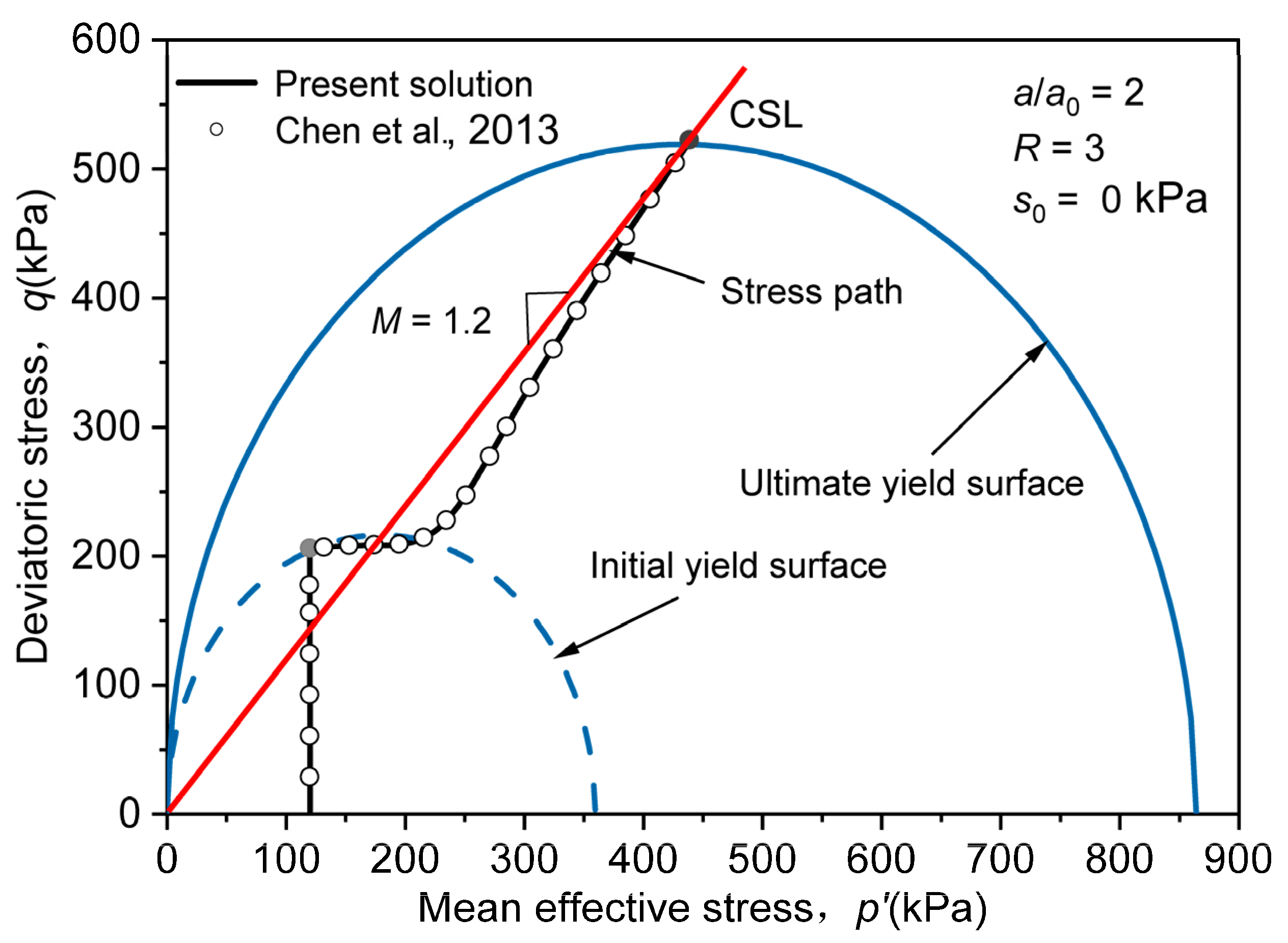
Figure 8 presents a comparison of the effective stress paths in the plane. It can be seen that the stress path derived from the proposed solution perfectly overlaps with that obtained by [21]. This demonstrates that the proposed solution can successfully degenerate into the calculation results of the drained solution for saturated soils in [21], further verifying the validity of the proposed solution.
Figure 8.
Comparison between the effective stress path in plane and the solution of Chen et al. [21].
6.2. Comparative Analysis of Cavity Expansion Models
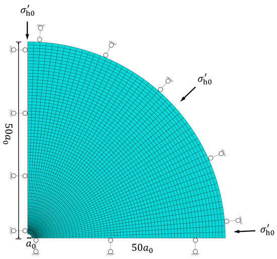
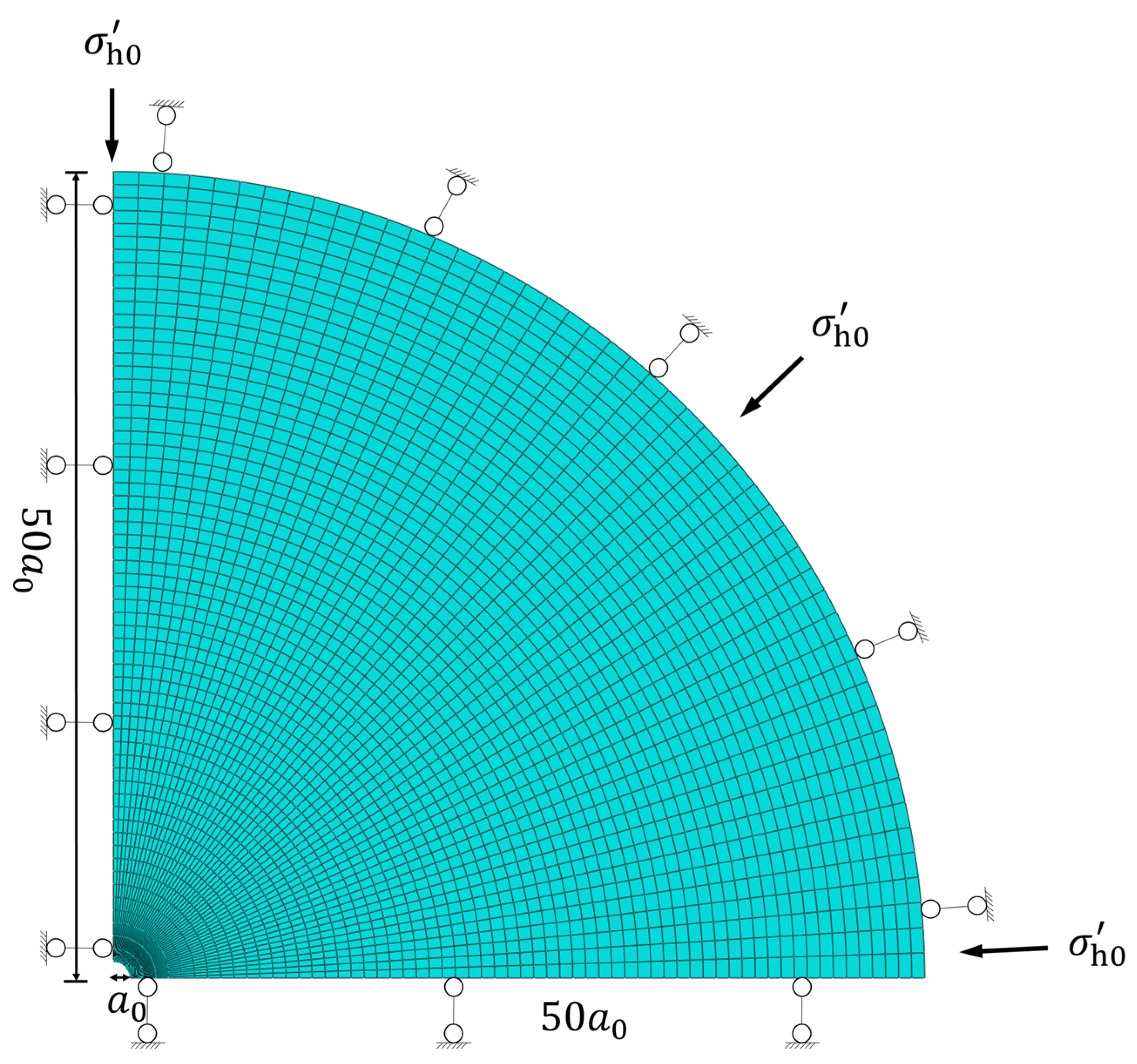
To fully verify the validity of the proposed solution, the calculation results from an ABAQUS finite element model are compared with the analytical solution. As shown in Figure 9, due to the geometric symmetry of the cylindrical cavity, only a quarter of the circular domain is analyzed in the finite element model to reduce computational expense. The outer boundary radius of the model is set to 50 times the initial radius of the cylindrical cavity. The elastoplastic constitutive model for unsaturated loess developed in this study is implemented into the ABAQUS software via the UMAT user subroutine to describe the elastoplastic hydro-mechanical coupled behavior of the loess during cylindrical cavity expansion. During the computation, field variables such as suction and degree of saturation are extracted, updated, and transferred using the GETVRM and USDFLD user subroutines, thereby achieving the hydro-mechanical coupled analysis of the loess constitutive model. The initial stress field is applied and brought to equilibrium through a GEOSTATIC analysis step, after which a uniform radial displacement is applied at the cavity wall in the subsequent loading step to simulate the expansion process.
Figure 9.
Finite element mesh, boundary conditions, and geometric configuration for quarter-domain cylindrical cavity expansion in ABAQUS.
To validate the proposed analytical/numerical solution, a finite element model was established in ABAQUS using the UMAT subroutine. Due to axisymmetry, a quarter-domain finite element mesh with appropriate boundary conditions was constructed, as illustrated in Figure 9. The normal displacement of the symmetry boundaries was constrained to ensure the axisymmetric deformation condition, while the outer radial boundary was equipped with a normal displacement constraint to prevent excessive radial movement and minimize boundary effects during cavity expansion. The initial cavity radius is denoted as , and the outer radial boundary was set at to mitigate boundary reflection effects under initial effective stress . Refined mesh refinement was implemented near the cavity wall to ensure computational precision. In Figure 9, is the radial extent of the outer boundary; is the initial horizontal effective stress applied at the far-field boundary.
The parameter values adopted in the finite element model are sourced from reference [36], as detailed in Table 1. For convenience, only the case with a coefficient of earth pressure at rest is considered; therefore, the values of and are identical across different working conditions in the parametric analysis. The other parameters are taken as: c = 0.01, d = 0.02, = 0.9, = 1.3, = 2, = 1.3, = 100 kPa, = 40 kPa, = 0.04, = 0.05, = 2.7, = .
Table 1.
Soil parameters used in calculation for case 1.
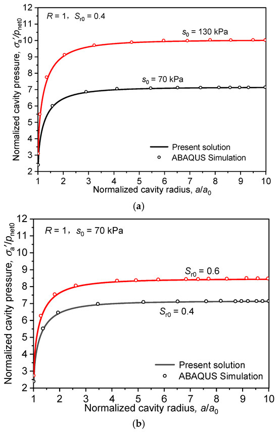
Figure 10 shows the comparison of the expansion pressure variations with the expansion radius under different initial suctions and initial degrees of saturation against the ABAQUS calculation results. In the figure, both the expansion pressure and the expansion radius are normalized. It can be seen that the proposed solution is in good agreement with the ABAQUS finite element simulation results, fully validating the reliability of the proposed solution. Concurrently, Figure 10a,b indicate that the expansion pressure of unsaturated loess increases with the increase in both initial suction and initial degree of saturation. The increase in suction and saturation enhances the effective mean stress and shear strength of the unsaturated soil skeleton, thereby leading to a higher cavity expansion pressure. This demonstrates that matric suction and degree of saturation have a significant influence on the cavity expansion pressure in unsaturated loess. The cavity expansion pressure and suction are normalized by the initial mean effective stress , the cavity radius is normalized by the initial cavity radius and compressive stress is positive. To further clarify the relationship between the initial degree of saturation and water content under the constant water content condition, the corresponding initial gravimetric water contents are calculated based on the soil parameters given in Table 1. The initial specific volume is , corresponding to an initial void ratio of , while the specific gravity of soil particles is . According to the relationship , the initial gravimetric water contents corresponding to and are and , respectively. Therefore, the two initial moisture conditions considered in this study correspond to approximately 40% and 60% of the fully saturated state, respectively, providing a quantitative basis for interpreting the influence of the initial water content on the hydro-mechanical response during cavity expansion.
Figure 10.
Variations of normalized cavity wall expansion pressure with normalized expansion radius: (a) under different initial suctions; (b) under different initial degrees of saturation.
Figure 11 illustrates the variations of cavity expansion pressure, suction, and degree of saturation with cavity radius under different initial suctions, where the expansion pressure, suction, and cavity radius are all normalized. Suction is normalized by the initial mean effective stress , and the cavity radius is normalized by the initial cavity radius and compressive stress is defined as positive.
Figure 11.
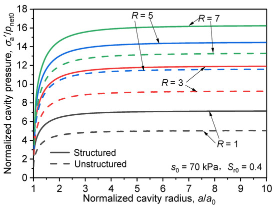
Variations of cavity expansion pressure with normalized cavity radius under different R with and without considering structure.
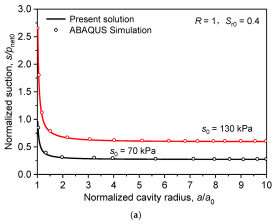
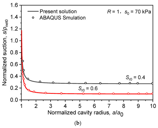
As can be seen from Figure 12, during the cylindrical cavity expansion process in unsaturated soil, the suction decreases rapidly with the increase in the cavity radius and then tends to stabilize. This behavior occurs because the cavity expansion causes soil compression and a reduction in specific volume; once the soil reaches the critical state, the specific volume remains constant, which leads to a decrease and eventual stabilization of suction under undrained conditions. With an increase in initial suction, the initial state of the soil becomes denser and exhibits higher strength. Consequently, the soil possesses a greater capacity to resist deformation, resulting in smaller volumetric compressive strains, which in turn reduces the magnitude of the suction drop and elevates the overall suction level. Furthermore, as shown in Figure 12b, at a higher initial degree of saturation, the drop in suction is more pronounced, rapidly approaching a fully saturated state (s = 0).
Figure 12.
Variations of normalized cavity wall suction with normalized expansion radius: (a) under different initial suctions; (b) under different initial degrees of saturation.
6.3. Analysis of Effects of Structure on Expansion Response
To investigate the effects of loess structure on the cavity expansion response, a comparative analysis is conducted between cases considering and neglecting soil structure. The parameter values used in the solution process are the same as those in Section 6.2. When soil structure is neglected, the structural parameters are set as: c = d = 0, = = 0, = → 0.
Figure 11 presents the variations of cavity wall expansion pressure with expansion radius under different overconsolidation ratios R for both structured and unstructured conditions. As shown in the figure, under the same R condition, the expansion pressure considering soil structure is overall higher than the unstructured result and increases more rapidly with the expansion radius. This is because the presence of structure gives the soil higher initial strength, requiring a greater expansion pressure to drive its expansion. As the cavity radius ratio increases, the expansion pressures for both cases tend toward stable values. However, the expansion pressure considering structure remains higher than that neglecting structure, demonstrating that the structural characteristics of loess have a significant influence on the cavity expansion pressure.
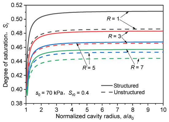
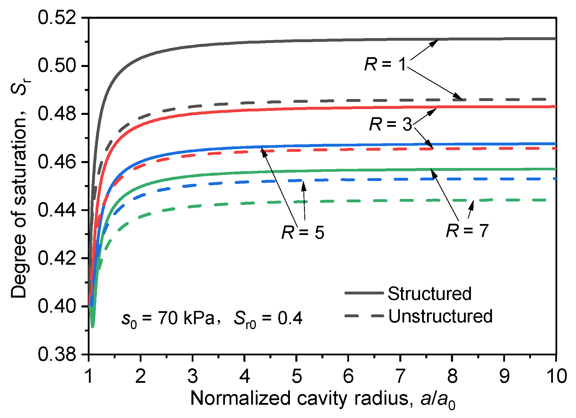
Figure 13 plots the variations of the degree of saturation at the cavity wall with the expansion radius for both structured and unstructured conditions. It can be observed that the degree of saturation at the cavity wall obtained without considering structure is consistently higher than that obtained when structure is taken into account, and its rate of increase with the expansion radius is also faster. This phenomenon occurs because structural degradation causes the pore structure to become progressively interconnected, which enhances the moisture migration capability, accelerates suction attenuation, and reduces its steady-state value. The reduction in suction further weakens the effective stress and promotes volumetric compaction, accelerating the transformation of macropores into mesopores and micropores, which ultimately manifests as a higher magnitude of increase in the degree of saturation.
Figure 13.
Variations of degree of saturation with normalized cavity radius under different with and without considering structure.
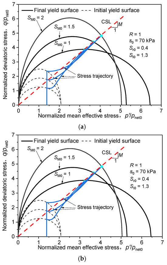
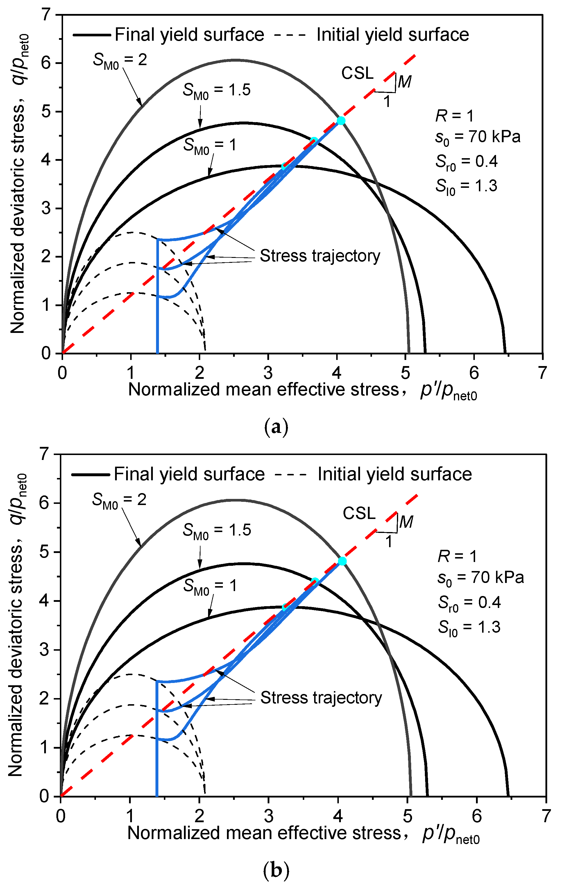
Figure 14 illustrates the influences of the structural parameters and on the evolution of the soil yield surface and the stress paths during the cavity expansion process in unsaturated loess. The stress variables in this figure are presented in normalized form, where and are normalized by the initial mean effective stress .
Figure 14.
Stress paths in plane under different structural parameters. (a) Initial yield stress structural parameter ; (b) initial frictional strength structural parameter .
As shown in Figure 14a, with the increase in , the enveloping ranges of both the initial and final yield surfaces expand significantly, indicating that structural enhancement can markedly improve the mean effective stress and deviatoric stress that the soil can sustain. When is large, the soil exhibits high stiffness during the initial stage of loading. However, once the stress exceeds the structural bearing limit, sudden structural failure occurs, causing a distinct deflection in the stress path and a pronounced post-peak softening feature, followed by gradual convergence toward the critical state line (CSL). In contrast to Figure 14a, an increase in mainly reinforces the expansion capability of the yield surface along the direction, thereby significantly enhancing the shear strength of the soil. As increases, the overall level of the stress path rises noticeably; nevertheless, the stress trajectories under different working conditions eventually converge to the CSL. This indicates that soil structure only alters the failure path and peak strength without affecting the final critical state. In summary, structured loess exhibits distinctive phased mechanical response characteristics during cavity expansion or pile driving processes: high stiffness and load-bearing capacity in the early stage, followed by sudden softening and strength degradation caused by structural disintegration in the later stage. Therefore, the influence of soil structure and its degradation mechanisms should be carefully considered in relevant engineering analyses.
Furthermore, initial water content (or degree of saturation ) plays a crucial governing role in dictating the hydraulic response and structural degradation rate of unsaturated loess during cavity expansion. Under lower initial water contents (higher initial matric suction , e.g., ), the soil exhibits higher initial stiffness and a larger limit expansion pressure due to suction hardening and preserved interparticle structural bonds. However, during the expansion process, the severe plastic compaction and pore structure collapse surrounding the cavity wall trigger a more rapid decay of matric suction and a sharp increase in the local degree of saturation compared to wetter cases (). Conversely, soils with higher initial water contents demonstrate lower limit expansion pressures but maintain a more gradual hydraulic evolution. This parametric contrast demonstrates that initial moisture state strongly controls both structural stability and dynamic hydraulic behavior, reinforcing the model’s physical interpretability and robustness across diverse moisture conditions.
6.4. Effect of Structure on Distribution of Variables Around Cavity
To investigate the influence of soil structure on the stress, suction, degree of saturation, and specific volume around the cavity, a comparative analysis is performed on the distribution of these variables around the cavity under both structured and unstructured conditions. The parameter values are taken as: c = 0.01, d = 0.02, = 0.9, = 1.3, = 1.5, = 2, = 120 kPa, = 40 kPa, = 0.13, = 0.03, = 2.74, = 0.3, = 0.15, = 0.03, and the remaining parameter values are listed in Table 2. For clarity and consistency in presenting the results, the stress, suction, and geometric variables are expressed in normalized form in the following analyses. The initial net mean stress is adopted as the reference value for stress-related quantities, while the initial cavity radius is used as the reference length. Accordingly, the normalized cavity radius and radial location are expressed as and , respectively, while the cavity expansion pressure, matric suction, and effective stress components are presented in normalized forms as , , , and , respectively. Here, denotes the cavity expansion pressure, and denotes the matric suction. The sign convention adopted throughout the analysis defines compressive stress as positive.
Table 2.
Soil parameters used in calculation in case 2.
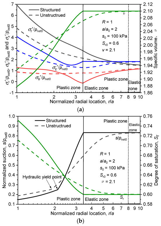
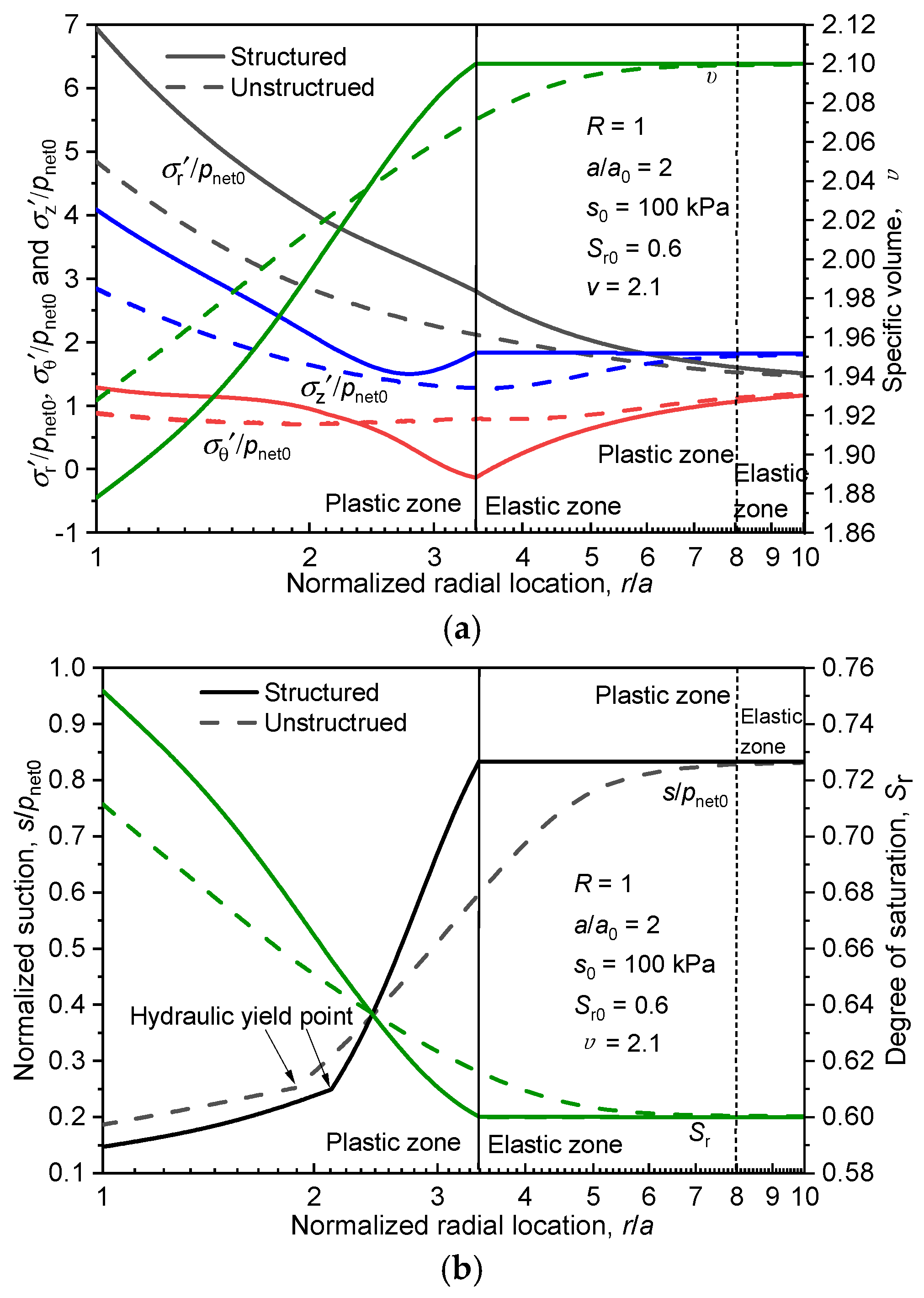
Figure 15 comparatively analyzes the distributions of normalized stress, specific volume, suction, and saturation of the surrounding soil along the radial coordinate , under conditions of an expansion ratio and R = 1, for cases both considering and neglecting soil structure. It can be seen that the structural characteristics of unsaturated loess exert a significant influence on the distribution of stress and specific volume around the cavity. Due to the presence of soil structure, the strength and deformation resistance of the loess are enhanced. Consequently, when structure is taken into account, the plastic zone around the cavity is smaller and the stress levels remain higher. If the soil structure of loess is neglected in cavity expansion analyses, the extent of the plastic zone will be significantly overestimated, while the effective stress around the cavity will be underestimated. Concurrently, it can be observed from the figure that under the structured condition, the distribution of variables within the elastic zone around the cavity is relatively gentle. However, upon entering the plastic zone, structural damage occurs in the loess, leading to rapid soil compression. This results in a higher rate of decrease in specific volume compared to the unstructured condition. Accordingly, both the rate of suction reduction and the rate of saturation increase are higher than those observed when soil structure is neglected.
Figure 15.
Comparison of the distributions of variables around cavity under structured and unstructured conditions (): (a) radial variations of normalized stress and specific volume in surrounding soil; (b) radial variations of suction and degree of saturation around cavity.
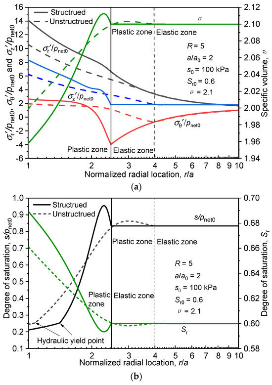
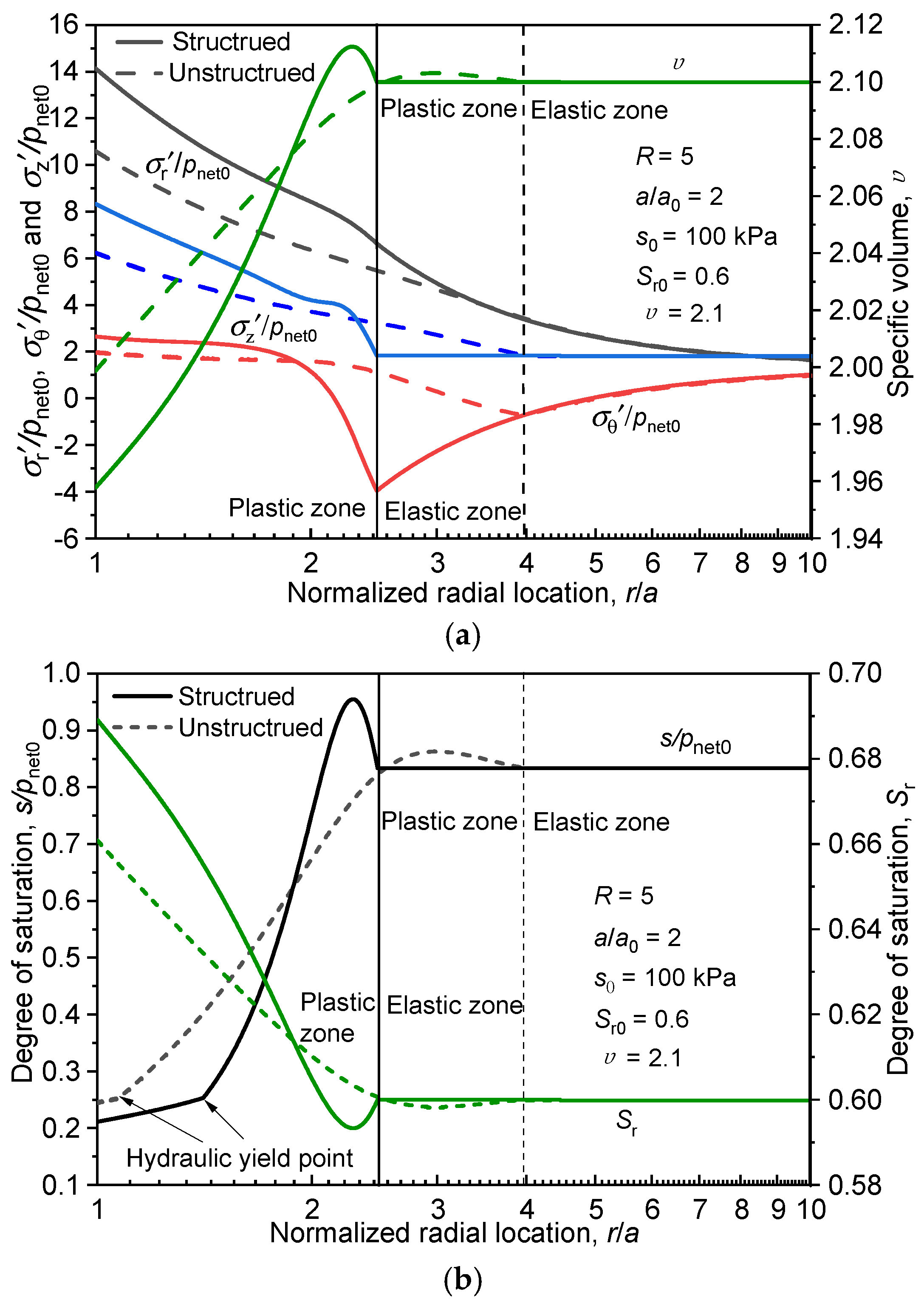
Figure 15 shows the comparison of the distributions of variables around the cavity under structured and unstructured conditions at an expansion radius of , : radial variations of normalized stress, specific volume, suction, and degree of saturation in the surrounding soil along the radial position . It can be observed that under the condition of an overconsolidation ratio , the strength and compressibility resistance of the soil are further enhanced, leading to a marked increase in the stress levels around the cavity and a reduction in the extent of the plastic zone compared to the case where . Concurrently, the distribution patterns of all variables around the cavity when are similar to those when . Although the stress level under the unstructured condition increases to some extent, it remains significantly lower than that under the structured condition. Under the structured condition, due to the structural damage of the soil, pore compression becomes more pronounced, resulting in a more noticeable range of variation for stress, specific volume, suction, and degree of saturation around the cavity. Notably, under overconsolidated conditions, the soil around the cavity undergoes post-yield softening followed by hardening. Consequently, a distinct shear dilation phenomenon occurs in the plastic zone near the elastoplastic boundary, manifested as an increase in specific volume relative to its initial value, which causes the suction to exceed its initial value. Subsequently, as the soil hardens, both the specific volume and suction decrease rapidly in the vicinity of the cavity wall.
Furthermore, as can be seen from Figure 16a,b, the suction distribution curves around the cavity exhibit a distinct inflection point near the cavity wall. This inflection point represents the hydraulic yield point, which fully demonstrates that the proposed solution can effectively determine the hydraulic state of the soil around the cavity and reasonably accounts for the influence of hydro-mechanical coupled behavior on cavity expansion. During the cavity expansion process, the soil surrounding the cavity is severely squeezed, and its pore structure undergoes significant compressive deformation, thereby inducing hydraulic yield in the soil. Concurrently, comparing the locations of the hydraulic yield point under structured and unstructured conditions reveals that the hydraulic yield point is located farther from the cavity wall when soil structure is considered. This indicates that following soil yield, pore compression is intense, causing the soil to enter the hydraulic yield state earlier. As the overconsolidation ratio increases, the strength and compressibility resistance of the soil are enhanced, which subsequently causes the hydraulic yield point to move closer to the cavity wall.
Figure 16.
Comparison of distributions of variables around cavity under structured and unstructured conditions (): (a) normalized stress and specific volume of soil around cavity; (b) suction and degree of saturation around cavity.
7. Conclusions
This study investigates the cylindrical cavity expansion problem in unsaturated structured loess from the perspective of symmetry principles. The fundamental axisymmetry of cylindrical cavity expansion, together with the resulting similarity of stress and strain paths around the cavity, forms the theoretical backbone of the entire formulation. By introducing saturation-dependent structural parameters into the Barcelona Basic Model (BBM), a hydro-mechanical coupled elastoplastic constitutive model is developed for structured loess. Leveraging the symmetry-induced dimensional reduction and self-similar solution properties, the problem is rigorously formulated as an initial value problem in the Lagrangian description. Utilizing this new constitutive model, a system of first-order ordinary differential governing equations for the cylindrical cavity expansion problem in unsaturated structured loess is established and solved numerically based on the Runge–Kutta method. After verifying the correctness of the proposed solution through both analytical degeneration and symmetry-exploiting finite element analysis, the cavity expansion response in unsaturated structured loess is explored in detail, leading to the following primary conclusions:
- (1)
- As suction tends toward zero, the analytical solution developed herein reduces to the classical cavity expansion solution for saturated soils under drained conditions. The favorable agreement between the present solution and finite element simulation results validates the rationality of the proposed formulation. Furthermore, by appropriately incorporating the coupling between soil structure and saturation, the proposed solution is capable of effectively characterizing the cavity expansion behavior in unsaturated structured loess.
- (2)
- The pressure required for cavity expansion exhibits an initial rapid increase followed by stabilization as the expansion ratio grows. Furthermore, the expansion pressure rises with increasing overconsolidation ratio R and initial suction. Throughout the expansion process, the compression of soil pores induces a sustained decline in suction alongside a rapid increase in saturation that eventually reaches equilibrium, clearly reflecting a significant hydro-mechanical coupling effect.
- (3)
- During the cavity expansion process, the soil closest to the cavity wall experiences the most intense squeezing. Moving radially outward from the cavity wall, and gradually decrease, yet their overall magnitudes increase with a higher overconsolidation ratio . Conversely, another variable increases radially from the cavity wall. Due to the most severe soil compression occurring at the cavity wall, the specific volume and suction reach their minimum values there, while the degree of saturation reaches its maximum. As the radial distance from the cavity wall increases, the degree of soil compression progressively weakens, and all variables gradually revert to their initial states at the elastoplastic boundary.
- (4)
- Soil structure significantly influences the cavity expansion response of unsaturated loess. The presence of loess structure enhances both the strength and the compressibility resistance of the soil, resulting in higher stress levels around the cavity and a smaller plastic zone radius. Neglecting the structural characteristics of loess will lead to an overestimation of the plastic zone extent and an underestimation of the stress levels around the cavity. Following the yield of structured loess, structural damage occurs and the soil pores compress rapidly, leading to a swift reduction in specific volume around the cavity, which correspondingly results in decreased suction and increased degree of saturation.
- (5)
- Under overconsolidated conditions, the soil surrounding the expanding cavity undergoes a post-yield softening followed by a hardening process, which corresponds to a phenomenon where the specific volume and suction near the elastoplastic boundary exceed their initial values. Compared to unstructured soils, structured loess experiences a rapid reduction in specific volume after yielding, causing it to enter the hydraulic yield state sooner. Furthermore, the position of the hydraulic yield point moves farther away from the cavity wall as the structural resistance and overconsolidation ratio increase.
- (6)
- From a methodological perspective, this study demonstrates the power of symmetry principles in solving complex geomechanical problems. The axisymmetry of cylindrical cavity expansion not only enables dimensional reduction from 3D to 1D, but also gives rise to the self-similarity of stress–strain paths that allows the elegant Lagrangian initial value problem formulation. This symmetry-based approach avoids the computational cost of full 3D analysis while maintaining rigorous accuracy, providing a paradigm for applying symmetry considerations to coupled hydro-mechanical problems in unsaturated soils. The successful application of symmetry arguments in this work highlights that recognizing and exploiting problem symmetries remains one of the most effective strategies for developing elegant and efficient semi-analytical solutions in geotechnical engineering.
The proposed semi-analytical formulation is developed under the standard assumptions of axisymmetry, spatial homogeneity, and isotropic initial stress states. These idealizations significantly reduce computational complexity, making the solution an efficient and accurate analytical tool for interpreting deep penetration tests (e.g., CPT, pressuremeter tests) and deep cylindrical cavity problems in unsaturated loess. However, the present formulation has inherent limitations: it does not account for initial anisotropic stress conditions, soil spatial variability, or boundary effects near shallow ground surfaces. For complex 3D scenarios involving severe cross-sectional distortion or pronounced soil anisotropy, full numerical finite element analyses remain necessary.
Author Contributions
Conceptualization, X.L. and M.Z.; Methodology, X.L. and M.Z.; Software, M.Z. and Z.X.; Validation, X.L. and M.Z.; Formal analysis, M.Z. and Z.X.; Investigation, X.L. and G.L.; Resources, Z.X. and G.L.; Data curation, Z.X. and X.L.; Writing—original draft, M.Z. and Z.X.; Writing—review and editing, X.L.; Visualization, X.L.; Supervision, X.L.; Project administration, X.L.; Funding acquisition, X.L. All authors have read and agreed to the published version of the manuscript.
Funding
The work has been supported by the Yan’an Science and Technology Project (No. 2025SLJBZ-001) and the Yulin Science and Technology Project (No. 2025-CXY-077).
Data Availability Statement
All data, models, or code generated or used during the study are available from the corresponding author by reasonable request.
Conflicts of Interest
Author Miao Zhang was employed by the company China Railway Liuyuan Group Co., Ltd. The remaining authors declare that the research was conducted in the absence of any commercial or financial relationships that could be construed as a potential conflict of interest.
Appendix A
By taking the partial derivatives of Equations (9) and (10), it can be obtained that:
where
where is the plastic potential function; is the generalized plastic strain rate.
Combining Equations (A1), (A3) and Equations (A2), (A3) yields:
where and denote the degradation rates of the initial yield stress structural parameter and the shear strength structural parameter, respectively. It yields:
Taking the derivatives of Equations (3) and (4), respectively, it can be obtained that:
where
and is a notation introduced for the convenience of derivation, .
Combining Equations (9) and (A5)–(A11), it can be obtained that:
Differentiating each variable in the yield equation yields:
Appendix B
According to the critical state elastoplastic theory, the mean effective stress p′ and the deviatoric stress q can be expressed as:
Taking the partial derivatives with respect to p’ and q, respectively, yields:
Combining Equations (26), (A13a), (A13b), (A16) and (A17) yields:
Similarly:
where
Combining Equations (A13f), (A13g) and (A19), and rearranging Equations (A12) and (A13), it can be obtained that:
where
According to Equations (A12) and (A18), it can be rearranged as:
Finally, combining Equations (9) and (24), the elastoplastic constitutive matrix for the cavity expansion problem can be expressed as:
where
Appendix C
The key steps of the fourth-order Runge–Kutta algorithm are as follows, where it is defined that :
where
The stress state at can be approximately determined as:
References
- Mo, P.Q.; Cai, G.J.; Wang, K.J.; Eslami, A.; Yu, H.S. Cavity expansion-based interpretation of piezocone penetration test (CPTu) data in clays. Géotechnique 2025, 75, 258–277. [Google Scholar] [CrossRef] [Scilit]
- Li, L.; Li, J.P.; Sun, D.A.; Gong, W.B. Time-dependent bearing capacity of a jacked pile: An analytical approach based on effective stress method. Ocean Eng. 2017, 143, 177–185. [Google Scholar] [CrossRef] [Scilit]
- Li, G.Y.; Mo, P.Q.; Yang, H.; Yu, H.S.; Qin, Y.J. Undrained cavity expansion–contraction analysis in CASM and its application for pressuremeter tests. Can. Geotech. J. 2025, 62, 1–19. [Google Scholar] [CrossRef] [Scilit]
- Li, L.; Li, J.; Sun, D.; Gong, W. Analysis of time-dependent bearing capacity of a driven pile in clayey soils by total stress method. Int. J. Geomech. 2017, 17, 04016156. [Google Scholar] [CrossRef] [Scilit]
- Liu, K.; Chen, J.J.; Kang, J.W. Analytical approach for short-term pile setup in clay considering destructuration. Ocean Eng. 2025, 318, 120132. [Google Scholar] [CrossRef] [Scilit]
- Ma, K.; Zhang, Y.P.; Mei, G.X.; El Naggar, M.H.; Liu, H.; Wu, W.B. An improved large-strain RITSS method for quasi-static jacked-pile installation and post-installation consolidation analysis in soft clay. Comput. Geotech. 2026, 196, 108202. [Google Scholar] [CrossRef] [Scilit]
- Li, B.; Fu, S.; Feng, X.; Shen, J.; Duan, B.; Pang, L. Cavity expansion theory with state-dependent Mohr-Coulomb model and its application to cone penetration tests. PLoS ONE 2025, 20, e0329935. [Google Scholar] [CrossRef] [Scilit] [PubMed]
- Wang, Y.Z.; Russell, A.R. Cavity expansions in two silty tailings with high degrees of saturation and a comparison to CPT results. Comput. Geotech. 2023, 164, 105682. [Google Scholar] [CrossRef] [Scilit]
- Randolph, M.F.; Carter, J.P.; Wroth, C.P. Driven piles in clay—The effects of installation and subsequent consolidation. Géotechnique 1979, 29, 361–393. [Google Scholar] [CrossRef] [Scilit]
- Zhou, H.; Kong, G.Q.; Liu, H.L. A semi-analytical solution for cylindrical cavity expansion in elastic–perfectly plastic soil under biaxial in situ stress field. Géotechnique 2016, 66, 584–595. [Google Scholar] [CrossRef] [Scilit]
- Zhang, X.H.; Wang, L.Z.; Hong, Y.; Li, S.Z. Semi-analytical elastic-viscoplastic solution for dynamic spherical cavity expansion in undrained clay considering rate and dynamic effects. Comput. Geotech. 2025, 183, 107209. [Google Scholar] [CrossRef] [Scilit]
- Zhou, H.; Wang, Z.L.; Liu, H.L.; Shen, H.; Ding, X.M. Undrained cylindrical and spherical cavity expansion in elastic-viscoplastic soils. Can. Geotech. J. 2021, 58, 1543–1557. [Google Scholar] [CrossRef] [Scilit]
- Chen, S.L.; Abousleiman, Y.N. Exact undrained elasto-plastic solution for cylindrical cavity expansion in modified Cam Clay soil. Géotechnique 2012, 62, 447–456. [Google Scholar] [CrossRef] [Scilit]
- Cao, L.F.; Teh, C.I.; Chang, M.F. Undrained cavity expansion in modified Cam clay I: Theoretical analysis. Géotechnique 2001, 51, 323–334. [Google Scholar] [CrossRef]
- Zhou, H.; Liu, H.; Kong, G.; Huang, X. Analytical solution of undrained cylindrical cavity expansion in saturated soil under anisotropic initial stress. Comput. Geotech. 2014, 55, 232–239. [Google Scholar] [CrossRef] [Scilit]
- Pang, L.; Jiang, C.; Zhang, C.Y. Cylindrical cavity expansion-contraction solutions in undrained MCC soils with the auxiliary variable approach. Appl. Math. Model. 2025, 137, 115722. [Google Scholar] [CrossRef] [Scilit]
- Chen, C.; Yan, L.; Zhang, X.W.; Wang, Y.; Sun, Z.H.; Xu, M.B. Theoretical solution for drained cylindrical cavity expansion in sands incorporating fabric anisotropy using the SANISAND-F model. Comput. Geotech. 2025, 186, 107380. [Google Scholar] [CrossRef] [Scilit]
- Collins, I.F.; Stimpson, J.R. Similarity solutions for drained and undrained cavity expansions in soils. Géotechnique 1994, 44, 21–34. [Google Scholar] [CrossRef] [Scilit]
- Collins, I.F.; Pender, M.J.; Yan, W. Cavity expansion in sands under drained loading conditions. Int. J. Numer. Anal. Methods Geomech. 1992, 16, 3–23. [Google Scholar] [CrossRef] [Scilit]
- Yu, H.S.; Rowe, R.K. Plasticity solutions for soil behaviour around contracting cavities and tunnels. Int. J. Numer. Anal. Methods Geomech. 1999, 23, 1245–1279. [Google Scholar] [CrossRef]
- Chen, S.L.; Abousleiman, Y.N. Exact drained solution for cylindrical cavity expansion in modified Cam Clay soil. Géotechnique 2013, 63, 510–517. [Google Scholar] [CrossRef] [Scilit]
- Chen, S.L.; Abousleiman, Y.N. Drained and undrained analyses of cylindrical cavity contractions by bounding surface plasticity. Can. Geotech. J. 2016, 53, 1398–1411. [Google Scholar] [CrossRef] [Scilit]
- Li, L.; Li, J.; Sun, D. Anisotropically elasto-plastic solution to undrained cylindrical cavity expansion in K0-consolidated clay. Comput. Geotech. 2016, 73, 83–90. [Google Scholar] [CrossRef] [Scilit]
- Dafalias, Y.F. An anisotropic critical state clay plasticity model. In Proceedings of the 2nd International Conference on Constitutive Laws for Engineering Materials: Theory and Applications, Tucson, AZ, USA, 5–8 January 1987; Volume 1, pp. 513–521. [Google Scholar]
- Russell, A.R.; Khalili, N. On the problem of cavity expansion in unsaturated soils. Comput. Mech. 2006, 37, 311–330. [Google Scholar] [CrossRef] [Scilit]
- Chen, H.; Li, L.; Sun, D. Elastoplastic solutions for undrained and drained expansions of a cylindrical cavity in unsaturated soils. Comput. Geotech. 2020, 123, 103569. [Google Scholar] [CrossRef] [Scilit]
- Zhai, Z.; Ma, S.; Zhang, Y.; Zhang, C. Undrained solution of cylindrical cavity expansion for unsaturated soils with modified Cam-clay model. IOP Conf. Ser. Earth Environ. Sci. 2021, 787, 012159. [Google Scholar] [CrossRef] [Scilit]
- Mántaras, F.M.; Schnaid, F. Cylindrical cavity expansion in dilatant cohesive-frictional materials. Géotechnique 2002, 52, 337–348. [Google Scholar] [CrossRef] [Scilit]
- Schnaid, F.; Mántaras, F.M. Cavity expansion in cemented materials: Structure degradation effects. Géotechnique 2003, 53, 797–807. [Google Scholar] [CrossRef]
- Sivasithamparam, N.; Castro, J. Undrained cylindrical cavity expansion in clays with fabric anisotropy and structure: Theoretical solution. Comput. Geotech. 2020, 120, 103386. [Google Scholar] [CrossRef] [Scilit]
- Li, J.; Gong, W.; Li, L.; Liu, F. Drained elastoplastic solution for cylindrical cavity expansion in K0-consolidated anisotropic soil. J. Eng. Mech. 2017, 143, 04017133. [Google Scholar] [CrossRef] [Scilit]
- Li, J.; Zhou, P.; Li, L.; Xie, F. Elastoplastic solution of drained expansion of a cylindrical cavity in structured soils considering structure degradation. Comput. Geotech. 2021, 133, 104051. [Google Scholar] [CrossRef] [Scilit]
- Alonso, E.-E.; Gens, A.; Josa, A. A constitutive model for partially saturated soils. Géotechnique 1990, 40, 405–430. [Google Scholar] [CrossRef] [Scilit]
- Taiebat, M.; Dafalias, Y.F.; Peek, R. A destructuration theory and its application to SANICLAY model. Int. J. Numer. Anal. Methods Geomech. 2010, 44, 1009–1040. [Google Scholar] [CrossRef] [Scilit]
- Sun, D.; Sheng, D.; Xiang, L.; Sloan, S.W. Elastoplastic prediction of hydro-mechanical behaviour of unsaturated soils under undrained conditions. Comput. Geotech. 2008, 35, 845–852. [Google Scholar] [CrossRef] [Scilit]
- Li, L.; Chen, H.; Li, J.; Sun, D.A. An elastoplastic solution for cylindrical cavity expansion under constant water content conditions in anisotropic unsaturated soils. Comput. Geotech. 2021, 139, 104323. [Google Scholar] [CrossRef] [Scilit]

Disclaimer/Publisher’s Note: The statements, opinions and data contained in all publications are solely those of the individual author(s) and contributor(s) and not of MDPI and/or the editor(s). MDPI and/or the editor(s) disclaim responsibility for any injury to people or property resulting from any ideas, methods, instructions or products referred to in the content. |
© 2026 by the authors. Licensee MDPI, Basel, Switzerland. This article is an open access article distributed under the terms and conditions of the Creative Commons Attribution (CC BY) license.