


Abstract
Deep-buried tunnels excavated in soft-hard interbedded rock masses under high in-situ stresses frequently suffer from severe asymmetric squeezing. To elucidate the multi-scale controlling mechanism of the bedding dip angle (), a finite–discrete element method (FDEM) model was developed on the Abaqus platform using the Muzhailing Tunnel as an engineering prototype. The model couples the Mohr–Coulomb criterion for rock matrix plasticization with zero-thickness cohesive elements for interface debonding and shear slip. Following specimen-scale validation against multi-orientation uniaxial compression tests (average peak strength error of 4.67%) and a qualitative consistency check against field failure patterns, the model was employed to investigate the evolution of surrounding-rock deformation, interface damage, and matrix plastic zones across –. Results demonstrate that maximum radial convergence responds non-monotonically to the bedding dip, peaking at (74.47 mm), which is approximately 52% larger than the minimum at (48.97 mm), defining a prominent deformation amplification window within –. An asymmetry index () quantifies the pronounced bias induced by inclined strata, reaching a maximum of 0.153 at . Dominant deformation zones migrate systematically along the perimeter governed by the geometric tangency between bedding planes and the excavation profile; uniquely, intense interlayer shear slip at shifts the peak convergence anomaly to the right sidewall. Crucially, macroscopic convergence, interface damage, and matrix plasticization evolve asynchronously, where modest radial convergence may mask substantial subsurface interlayer slip. The asymmetric instability is fundamentally a progressive, cross-scale process driven by the synergy between discontinuous interface slip and continuous matrix shear yielding, providing theoretical guidelines for non-symmetric support design in deep stratified ground.
1. Introduction
As underground space development progressively extends into deep and complex geological environments, transportation tunnels and mining roadways frequently traverse soft-hard interbedded rock masses, typically represented by sand-mudstone interbeds, phyllite, and coal-bearing strata [1,2,3,4]. Under the superposition of high in-situ stresses and frequent excavation disturbances, soft-hard interbedded surrounding rock is highly susceptible to severe engineering geohazards, such as severe asymmetric squeezing, biased floor heave, and localized shear crushing [5,6,7,8,9]. For instance, during the excavation of the Muzhailing Tunnel through moderately to steeply inclined carbonaceous phyllite and sandy slate interbeds (), severe asymmetric convergence exceeding 40–60 cm occurred predominantly on the bedding-tangent side, resulting in unilateral buckling distortion of steel arches and extensive shotcrete cracking [5,7,8]. Similarly, in the Yangshan Tunnel traversing monoclinic soft-hard interbedded mudstone and sandstone (), incompatible interlayer shear slip and flexural bending triggered localized roof collapse and severe eccentric distortion of the primary lining [6]. Comparable dip-controlled eccentric squeezing and support failures have also been documented in deep phyllite tunnels [4,9], demonstrating that conventional uniform ring support often fails to accommodate directional rock mass instability. Clarifying the progressive evolution characteristics and triggering mechanisms of such asymmetric large deformations in soft-hard interbedded ground is an essential prerequisite for scientific support design and long-term stability maintenance in deep underground engineering [10].
The mechanical essence of asymmetric deformation around underground openings in layered rock masses stems from the profound coupling between the initial in-situ stress field (the mechanical driving field) and the spatial orientation of strata (the geometric constraint field) [11,12]. Extensive theoretical analyses and laboratory tests have demonstrated that the presence of weak bedding planes endows stratified rock masses with pronounced transversely isotropic characteristics in terms of their deformation modulus, shear strength, and failure modes [13,14,15,16]. This macroscopic asymmetric failure fundamentally originates from cross-scale, non-linear mechanical interactions: at the “micro-matrix scale”, the soft and hard rock layers undergo differentiated shear degradation and non-uniform microcrack propagation under deviatoric stress concentrations [17,18]; at the “meso-bedding scale”, the sharp stiffness contrast between alternating soft and hard strata inevitably triggers incompatible interlayer shear slip, tensile delamination, and localized frictional weakening upon excavation unloading [19,20].
Driven by this stress-structure coupling, the relative spatial relationship between the opening geometry and the bedding orientation governs the distinct divergence of failure modes in the surrounding rock. In large-span transportation tunnels, long-span strata subjected to tangential compressive stress are prone to flexural bending and buckling failure, resulting in severe eccentric loading on the primary support on the loading side [21,22]. Field observations indicate that as the bedding dip angle varies from gentle to steep inclinations, the failure mode transitions from symmetric roof delamination () to unilateral shoulder flexural buckling and sidewall shear sliding (), and eventually to sub-vertical sidewall slabbing () [4,5,21,22]. This structural transition disrupts the geometric and mechanical symmetry of the opening—a phenomenon termed ‘symmetry breaking’—which necessitates a shift from conventional symmetric support to targeted asymmetric reinforcement. Numerical analyses and physical model tests have further revealed that the degree of asymmetric stress concentration and the depth of plastic zone propagation are highly sensitive to the strata orientation; variations in the bedding dip angle systematically induce spatial migration of both the principal stress directions and the dominant deformation zones around the tunnel perimeter [23,24,25]. Therefore, systematically elucidating the controlling mechanism of the bedding dip angle on the internal stress transfer path, the migration of dominant deformation zones, and the resulting asymmetric failure patterns is of vital scientific and engineering importance.
To decipher the asymmetric failure mechanisms of layered rock masses, extensive investigations have been conducted worldwide using analytical solutions, physical model tests, and numerical simulations. Analytical methods typically employ structural element models (e.g., elastically supported beams and composite beams) to evaluate the deflection and fracture of localized roofs or sidewalls; however, they struggle to capture the macroscopic elastoplastic flow and discontinuous fracturing across the entire domain at the engineering scale. While laboratory mechanical tests can visually characterize the orientation-dependent damage and failure of anisotropic rock specimens under different dip angles [15,16]. They are constrained by specimen dimensions and cannot fully reproduce the severe in-situ stress gradients and unloading boundary conditions found around real openings. In contrast, numerical simulations offer distinct advantages in resolving strong non-linearities and complex boundary conditions, thereby serving as a primary approach for investigating failure mechanisms in deep layered ground.
Within the framework of numerical analysis, conventional continuum methods (such as the finite element method, FEM, and finite difference method, FDM) typically describe the response of stratified rock masses using equivalent continuum theories or the ubiquitous-joint model [26,27]. Although well-suited for capturing macroscopic deformation trends and identifying potential hazard zones, these continuum approaches exhibit intrinsic limitations in explicitly resolving highly discontinuous behaviors, such as interlayer tensile cracking, shear slip-induced spalling, and progressive interface debonding between alternating soft and hard strata. To overcome these shortcomings, discontinuum approaches such as UDEC and 3DEC treat layered rock masses as assemblies of discrete blocks separated by discontinuities, thereby effectively capturing interlayer sliding and localized block detachment [28,29]. Nevertheless, purely discrete element methods still face computational bottlenecks when attempting to accurately resolve the continuous elastoplastic damage evolution within the intact rock matrix and its dynamic synergy with structural plane failure.
In recent years, the finite–discrete element method (FDEM) has emerged as a promising approach for modeling the progressive transition from continuous deformation to discontinuous fracturing in layered rock masses [30,31]. This method retains the capability of the finite element formulation to resolve continuous stress evolution and matrix plastic yielding with high fidelity, while concurrently embedding zero-thickness cohesive elements along weak bedding interfaces. By incorporating traction-separation laws, FDEM explicitly simulates tensile opening, shear slip, and bonding degradation along structural discontinuities [32,33]. Lisjak et al. [32] pioneered the application of this coupled continuum–discontinuum approach to simulate brittle spalling around unsupported openings in anisotropic Opalinus clay shale, verifying the efficacy of FDEM in capturing anisotropic fracture paths. Subsequently, Deng et al. [34] and Liu et al. [35] extended FDEM to predict anisotropic fracture zones in deep tunnels and to formulate advanced cohesive damage constitutive formulations. More recently, FDEM has been successfully applied to analyze toppling failure mechanisms in soft-hard interbedded anti-dip slopes [36] and to assess asymmetric deformation control in tunnels in stratified ground [37], demonstrating its versatility in layered rock engineering.
Despite these substantial advancements, two major shortcomings remain in current FDEM and related numerical investigations. First, most existing studies simplify layered rock masses as a single homogeneous matrix dissected by dense discontinuity planes, neglecting the significant contrast in stiffness and strength between alternating “soft” and “hard” lithological units. For soft-hard interbedded surrounding rock characterized by stark property discrepancies between matrices, the synergistic evolution between continuous matrix plasticization and discontinuous interface slip under the control of bedding dip angle remains insufficiently quantified. Second, existing numerical models are predominantly validated against single-level benchmarks—either small-scale laboratory tests or qualitative field observations. A comprehensive validation framework integrating specimen-scale quantitative tests with field-scale qualitative consistency checks, from multi-orientation laboratory experiments to engineering-scale convergence monitoring, remains scarce, thereby limiting the reliability of numerical extrapolations to field practices.
To address these knowledge gaps, this study establishes an FDEM coupled numerical model tailored for soft-hard interbedded surrounding rock on the Abaqus platform. The elastoplastic yielding of both the soft and hard rock matrices is described using the Mohr–Coulomb criterion, while zero-thickness cohesive elements are inserted along the lithological interfaces to explicitly capture discontinuous interlayer damage evolution. The model is first calibrated and validated against multi-orientation uniaxial compression tests on carbonaceous slate specimens to verify its capability in capturing anisotropic matrix responses and mesoscale interface degradation. Subsequently, taking the soft-hard interbedded section of the No. 3 inclined shaft in the Muzhailing Tunnel as an engineering prototype, the model is employed to systematically investigate the asymmetric radial convergence, the migration trajectory of dominant deformation zones, the spatial distribution of bedding interface damage, and the morphology of matrix plastic zones across different bedding dip angles, which are further cross-validated with field-monitored convergence data. By examining the synergistic competition between discontinuous interface damage and continuous matrix plasticization, this study reveals the governing mechanism of bedding dip angle on the asymmetric instability of tunnels in deep interbedded rock masses, providing a solid theoretical foundation for targeted, non-symmetric support design in high-stress stratified ground.
2. Engineering Geological Background
2.1. Project Overview and Geological Setting of the Tunnel Site
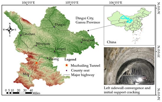
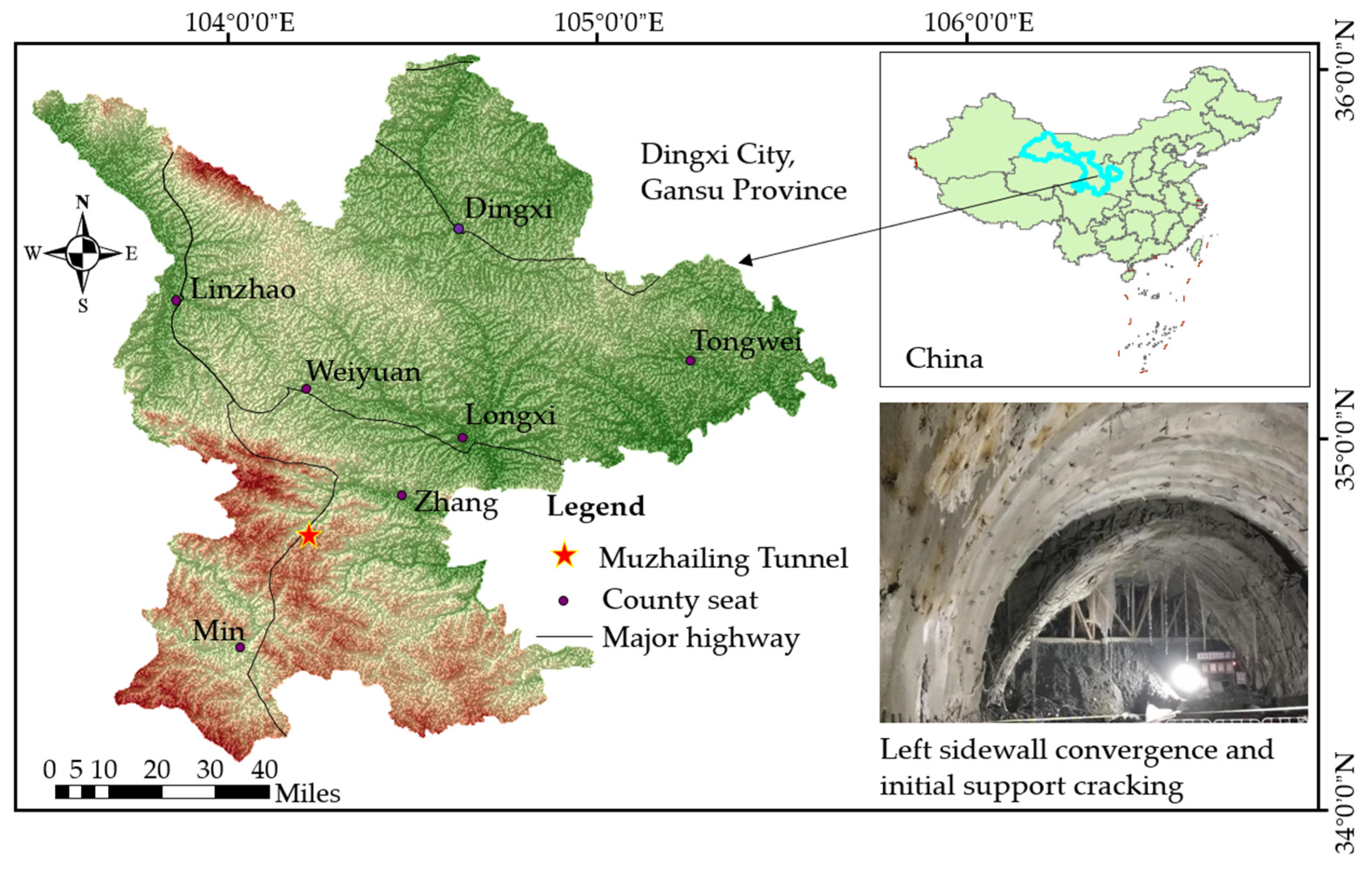
The Muzhailing Tunnel is a critical control project along the Weiyuan–Wudu Expressway, situated at the border between Zhangxian and Minxian counties in Gansu Province, China. Geomorphologically, it is located in the tectonically erosional low-to-medium mountain region of the West Qinling Mountains. The tunnel is designed as separated twin-tube bores, with both the left and right lines extending approximately 15 km in length. The maximum overburden depth reaches approximately 629 m, and three auxiliary construction inclined shafts were excavated. The tunnel area is characterized by high, steep peaks, deeply incised valleys, and pronounced topographic relief. Driven by intense regional tectonic activities, the deep-buried sections have endured sustained high tectonic stresses over geological history. In particular, the sections traversed by the No. 2 and No. 3 inclined shafts feature deep burial depths and intensely fractured rock masses, representing typical engineering sections where severe large deformations of weak stratified surrounding rocks were concentrated during construction. The geographical location of the study area is shown in Figure 1.
Figure 1.
Overview of the study area.
Under the influence of regional tectonic compression, folding, and faulting, geological discontinuities such as joints, slaty cleavage, and bedding planes are extensively developed within the rock mass. Locally intersecting fault fracture zones and their associated influence zones, the surrounding rock exhibits poor overall integrity. Particularly in the sections of the No. 2 and No. 3 inclined shafts, inclined stratified structures are well developed, and strata attitudes vary considerably. This geological framework provides critical structural prerequisites for the development of directional deformation and asymmetric failure upon excavation. The surrounding rock in the deep-buried sections is dominated by weak strata such as carbonaceous slate and carbonaceous phyllite, locally interbedded with relatively competent lithologies including sandstone, sandy slate, limestone, and shale. Geological exposure in the No. 2 and No. 3 inclined shafts reveals prominent layered structures: the slate is predominantly grayish-black, thinly-to-medium bedded, intensely fractured with well-developed bedding and joint fissures, and comprehensively classified as Grade V surrounding rock according to the Chinese rock mass classification standard.
Field geological surveys indicate that the individual layer thickness of the slate ranges predominantly from 10 to 30 cm, intimately accompanied by sandy strata and other competent interbeds of varying scales, thereby constituting a composite soft-hard interbedded rock mass with stark contrasts in mechanical properties. The sharp divergence in stiffness and strength between the soft and hard strata prevents the surrounding rock from deforming compatibly upon excavation unloading: the incompetent carbonaceous layers readily undergo compressive yielding and plastic extrusion, whereas the competent sandy layers exhibit higher deformation resistance and are prone to flexural bending, buckling rupture, and localized spalling under high stress concentrations. Consequently, the lithological interfaces are subjected to tensile delamination and interlayer shear slip. Furthermore, groundwater in the tunnel area is dominated by bedrock fissure water, locally accompanied by karst water and pore water, which readily migrates and accumulates along the interconnected cleavage, bedding planes, and tectonic fractures. The pronounced water sensitivity of carbonaceous slate and carbonaceous phyllite exacerbates water–rock interactions, which further degrades the strength and interfacial cohesive bond of the weak strata, accelerating fracture propagation and interlayer slip. Under the combined action of high in-situ stresses and excavation unloading, these hydro-mechanical processes dramatically amplify the incompatible deformation between alternating soft and hard strata, exacerbating localized rock mass instability. Consequently, surrounding-rock failure exhibits distinct bedding-controlled failure mechanisms, providing the fundamental lithological and structural basis for the spatial asymmetry of tunnel deformation.
2.2. In-Situ Stress Environment and Typical Research Section
The Muzhailing Tunnel is situated in a region governed by tectonic compressive stresses. In-situ stress measurements were performed at the tunnel site by the Institute of Geomechanics, Chinese Academy of Geological Sciences, utilizing the hydraulic fracturing method. The measurement boreholes were located near chainages AK214+738 and AK219+422.8, with testing depths of approximately 492 m and 499 m, respectively. The testing results demonstrate pronounced tectonic stress characteristics: the maximum horizontal principal stress () is greater than the minimum horizontal principal stress () and generally exceeds the vertical stress () at the corresponding depth, indicating that horizontal tectonic stress dominates the initial virgin stress field. The measured orientations of the maximum horizontal principal stress are approximately NE39.6° and NE34.1°, which are in close agreement with the regional tectonic stress field. Crucially, these stress orientations intersect the longitudinal axes of the No. 2 and No. 3 inclined shafts at an angle of approximately 37–42°, forming an unfavorable stress–structure geometric relationship. In parts of the deep-buried sections of the Muzhailing Tunnel, the strength–stress ratio—defined as the ratio of the uniaxial saturated compressive strength of the rock mass () to the maximum principal stress ()—is generally , confirming that the surrounding rock mass is situated in an extremely high in-situ stress environment.
The combination of high horizontal tectonic stresses and inclined bedding planes constitutes the primary geomechanical background driving the asymmetric deformation in the Muzhailing Tunnel. On the one hand, excavation unloading induces stress redistribution around the opening, rendering the weak strata more susceptible to compressive yielding and plastic squeezing. On the other hand, the inclined bedding planes significantly alter the internal load-transfer paths within the surrounding rock, subjecting the interfaces simultaneously to normal compression and tangential shear. When an unfavorable geometric relationship develops between the principal stress orientation and strata attitude, distinct discrepancies arise in interlayer shear slip, strata bending, and matrix plastic damage across different peripheral zones, ultimately triggering directional asymmetric convergence and localized structural failure.
The No. 3 inclined shaft of the Muzhailing Tunnel has a total length of approximately 1.27 km, with a maximum burial depth of about 455 m. The exposed surrounding rock primarily consists of alternating strata of carbonaceous phyllite and sandy slate with a wide variation in bedding dip angles, serving as a representative engineering section for investigating the dip angle effect on asymmetric tunnel deformation. During excavation, pronounced engineering phenomena—including visible interlayer shearing, flexural buckling of strata, fissure water ingress, and severe asymmetric distortion of the primary support—were extensively observed. Among these, chainage section K1+140 possesses comprehensive convergence monitoring records, providing a reliable benchmark for engineering-scale numerical validation. Accordingly, section K1+140 of the No. 3 inclined shaft is adopted as the prototype to establish the FDEM model for soft-hard interbedded ground. By varying the bedding dip angle while maintaining consistent lithological combinations and in-situ stress characteristics, this study aims to systematically elucidate the controlling mechanism of the bedding dip angle on asymmetric deformation, interlayer interface damage, and the progressive evolution of matrix plastic failure.
3. Establishment and Validation of the FDEM Coupled Numerical Model for Layered Rock Masses
3.1. Cohesive Damage Constitutive Model for Bedding Interfaces
Bedding planes represent critical structural discontinuities that govern the deformation compatibility and progressive failure of stratified rock masses. Owing to the pronounced contrast in strength and stiffness between the intact rock matrix and bedding interfaces, excavation disturbances readily induce localized stress concentrations along these discontinuities, subsequently triggering mixed-mode failure characterized by tensile opening (delamination), shear slip, and cohesive bonding degradation. Consequently, conventional continuum models struggle to realistically capture the complete progressive failure process of bedding planes transitioning from continuous deformation to discontinuous detachment.
To characterize the mechanical response of lithological interfaces, a coupled finite–discrete element method (FDEM) is implemented on the Abaqus platform by incorporating the cohesive zone model (CZM). By defining a constitutive traction–separation relationship, the CZM accurately reproduces the progressive failure stages of structural discontinuities, spanning from initial elastic deformation and damage initiation to complete interfacial failure. Originating from fracture mechanics for describing crack propagation, CZM theory effectively captures non-linear interface softening and has been extensively validated and applied in simulating the failure of rock discontinuities and composite interfaces, thereby providing a solid theoretical foundation for the interface modeling in this study [32,38,39,40]. In soft-hard interbedded rock masses, the lithological interfaces are weakly cemented sedimentary contacts that govern deformation incompatibility. Compared with alternative interface modeling approaches, the zero-thickness CZM is particularly suitable for these geological conditions: (i) unlike equivalent continuum approaches (e.g., the ubiquitous-joint model [26]) that smear discontinuity effects across continuum elements, the CZM explicitly resolves discrete kinematic discontinuities, including normal opening (delamination) and tangential slip along bedding planes; and (ii) unlike purely frictional contact algorithms that neglect initial interfacial cohesion, the CZM combined with Coulomb contact friction continuously captures the progressive transition from intact elastic bonding and fracture-energy-governed bond degradation to post-failure frictional sliding. Regarding its scope and limitations, because zero-thickness cohesive elements are embedded solely along predefined bedding interfaces in this study, the model explicitly captures interlayer debonding and slip along bedding planes [32,37], while the intact rock layers between interfaces are modeled as elastoplastic continua (Section 3.2) without explicit intralayer crack propagation.
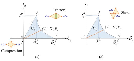
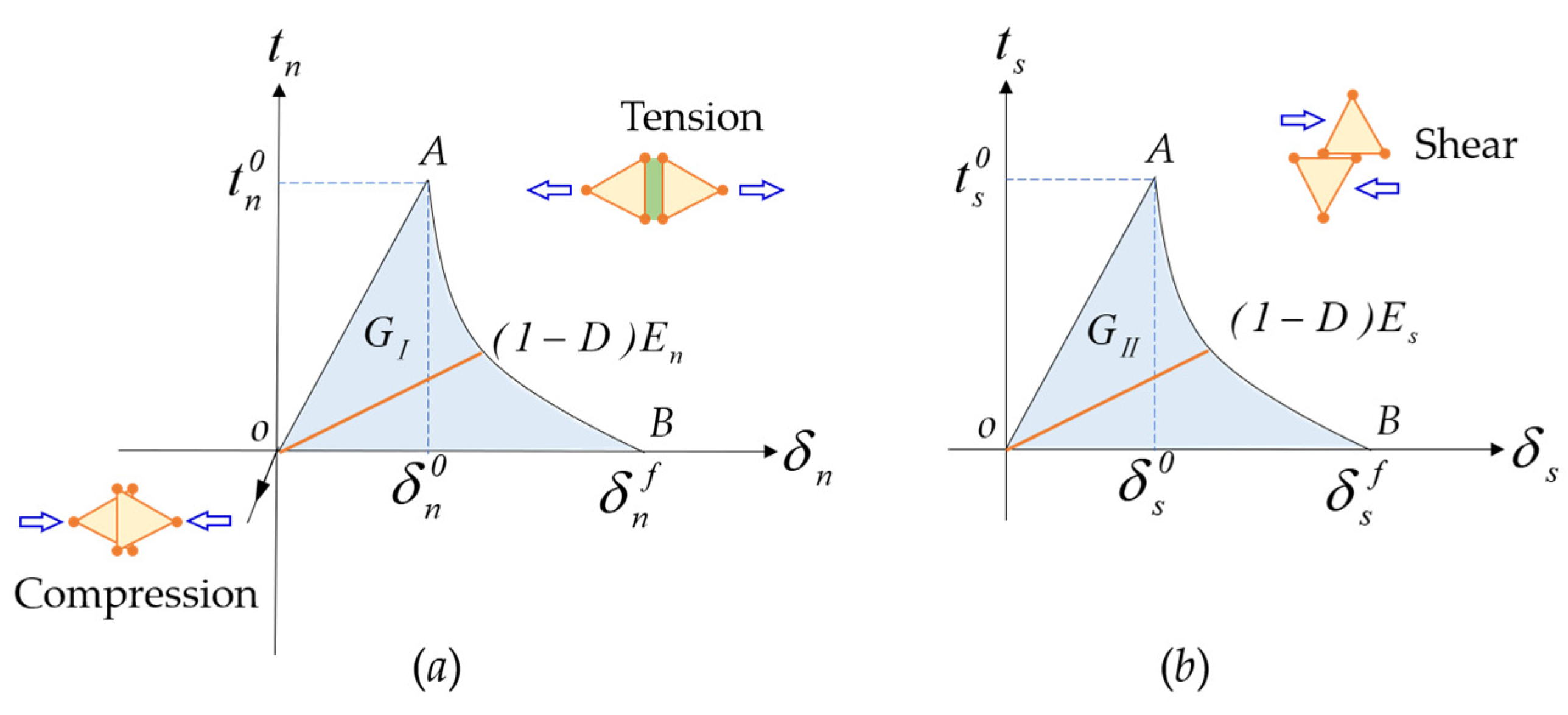
As depicted in Figure 2, the cohesive element characterizes the mechanical response of the bedding plane via a non-linear traction–separation relationship decomposed into normal and tangential modes [40,41]. In the normal direction (Figure 2a), under tensile loading (), the interface remains fully bonded during the initial stage OA (), and the normal traction () increases linearly up to the peak tensile strength () at the critical initiation displacement (). Under normal compression (), the interface resists interpenetration elastically via the normal penalty stiffness () without inducing damage or stiffness degradation. Similarly, in the tangential direction (Figure 2b), the shear traction () increases linearly with relative shear slip () during the elastic stage OA () until reaching the peak shear strength ().
Figure 2.
Traction–separation constitutive behavior of the cohesive interface: (a) normal tension and compression mode; (b) in-plane shear mode.
Once the interfacial traction reaches the peak strength (Point A), internal cohesive bonding begins to degrade, entering the damage evolution stage AB ( or ). With further separation increments, the load-bearing capacity progressively diminishes along a softening branch governed by the degraded stiffness . Ultimately, when the separation reaches the complete failure displacement ( or at Point B), the cohesive bond vanishes entirely (). The total area OAB enclosed by the traction–separation curve and the horizontal displacement axis () represents the total interfacial fracture energy per unit area ( or for Mode-I normal opening, and or for Mode-II shear slip, in ), which comprises both the pre-peak elastic energy stored up to and the post-peak softening energy dissipated from to [41,42].
Prior to damage initiation (Stage OA), the cohesive elements satisfy a linear elastic traction–separation law:
where denotes the traction stress vector comprising the normal and two shear components; is the corresponding relative separation displacement vector; and represents the interface stiffness matrix (with diagonal stiffness components and ). For zero-thickness cohesive elements, a unit constitutive thickness () is specified so that nominal strains are numerically equal to the relative separation displacements (), directly representing normal opening and interlayer shear slip.
When the interfacial traction satisfies the damage initiation criterion, the bedding plane undergoes cohesive degradation. The maximum nominal stress criterion is employed to determine the onset of damage [41,42]:
where , , and denote the peak nominal strengths in the normal and two shear directions, respectively; represents the Macaulay bracket, defined as , indicating that compressive normal stress does not induce tensile damage.
Following damage initiation (Stage AB), the interface stiffness degrades progressively according to the scalar damage variable . The traction stress components are expressed as [41,42]:
where is the undamaged traction stress calculated from the elastic traction–separation law; and is the damage variable ranging from 0 to 1. Specifically, corresponds to an undamaged, fully bonded interface, whereas indicates complete debonding, allowing relative separation or shear sliding between adjacent strata.
To describe mixed-mode fracture energy evolution, the Benzeggagh–Kenane (BK) energy criterion [43] is adopted, expressed as , where is the work done by shear tractions, is the total work, and is the material parameter. Once cohesive bonding is completely exhausted (), the debonded interfaces transition to Coulomb frictional sliding governed by the interfacial friction coefficient (, where residual shear resistance is ), thereby fully realizing the discontinuous interlayer failure characterization within the FDEM framework [35,43].
3.2. Mohr–Coulomb Elastoplastic Model for the Rock Matrix
The deformation and failure of stratified rock masses are governed not only by slip along bedding planes but also by yielding and damage evolution within the intact rock matrix. To characterize the shear yielding behavior of the rock matrix subjected to high in-situ stresses and excavation unloading, an isotropic linear elastic model is adopted to represent the pre-peak elastic stage, while the classical Mohr–Coulomb criterion is employed to capture the subsequent plastic yielding process.
The Mohr–Coulomb criterion postulates that failure in rock materials is primarily governed by a critical combination of normal stress and shear stress acting on the failure plane. Its shear strength envelope is expressed as [43,44]:
where is the cohesion, is the internal friction angle, is the normal stress acting on the failure plane, and denotes the shear stress.
For a generalized three-dimensional stress state, the Mohr–Coulomb yield function in stress invariant space can be formulated as [42,45]:
where is the mean normal stress (hydrostatic pressure), is the Mises equivalent stress, and represents a scaling parameter associated with the deviatoric stress state (governing the shape of the yield surface in the deviatoric plane as a function of the internal friction angle and the Lode angle).
To prevent excessive volumetric dilatancy under high geostresses, a non-associated plastic flow rule based on the hyperbolic plastic potential function [42,45] is employed, characterized by a dilation angle ( for carbonaceous phyllite and for sandy slate, Table 1). Furthermore, the rock matrices are treated as ideal elastoplastic media with constant strength parameters ( and ) that do not soften with accumulated plastic strain, while macroscopic tensile delamination is governed by the cohesive bedding interfaces.
Table 1.
Mechanical parameters of rock matrices and primary support.
Equation (5) inherently captures the pressure-dependent shear strength characteristics typical of geomaterials, making it well suited for describing the shear yielding and progressive plastic deformation of rock matrices such as carbonaceous phyllite and sandy slate under high in-situ stress environments. By coupling this Mohr–Coulomb matrix model with the cohesive interface damage model defined along the bedding planes, the numerical framework enables concurrent simulation of continuous plastic yielding within the intact rock matrix and discontinuous fracture evolution along the lithological interfaces throughout the excavation process [4,5,37].
3.3. Establishment of the FDEM Coupled Numerical Model for Layered Rock Masses
A finite–discrete element method (FDEM) coupled numerical model is developed within the Abaqus/Explicit dynamic computational framework. In this model, the intact rock matrix is discretized using solid continuum elements governed by the Mohr–Coulomb elastoplastic constitutive law, which captures the internal stress–strain response and the progressive evolution of matrix plastic yielding. Zero-thickness cohesive elements are pre-inserted along the bedding interfaces between adjacent strata, and a Coulomb friction coefficient () is incorporated across the contact pairs. Through the bilinear traction–separation relationship, the complete progressive failure process along the bedding planes—encompassing tensile delamination, shear slip, and cohesive bonding degradation—is explicitly simulated. All numerical simulations were conducted in Abaqus/Explicit (Version 2022). To guarantee a quasi-static mechanical response and suppress dynamic inertial effects, loading and excavation unloading were governed by a smooth-step amplitude function without artificial mass scaling, combined with standard bulk viscosity damping (). Quasi-static equilibrium was confirmed by verifying that the ratio of kinetic energy to internal strain energy () remained strictly below throughout the process and that boundary displacements reached a steady plateau.
The structural architecture of the developed FDEM coupled model is illustrated in Figure 3. Distinct from conventional continuum approaches that homogenize stratified rock masses into equivalent anisotropic media, the proposed framework independently and explicitly discretizes the rock matrix and the interlayer discontinuities: the intact rock matrix is represented by continuous finite elements, whereas the bedding planes are modeled using cohesive interface elements, thereby circumventing the empirical homogenization of structural planes. By virtue of this hybrid modeling strategy, the numerical model can explicitly capture discontinuous kinematic behaviors, such as normal separation and tangential slip along bedding interfaces. Furthermore, it enables direct and synchronous tracking of the spatial–temporal interactions among interfacial damage variables, relative interlayer shear displacements, matrix plastic zones, and displacement fields around the opening, providing a critical methodological foundation for deciphering the asymmetric failure mechanisms of soft-hard interbedded surrounding rock.
Figure 3.
FDEM coupled numerical model of layered rock mass.
3.4. FDEM Model Validation via Uniaxial Compression Tests on Layered Rock
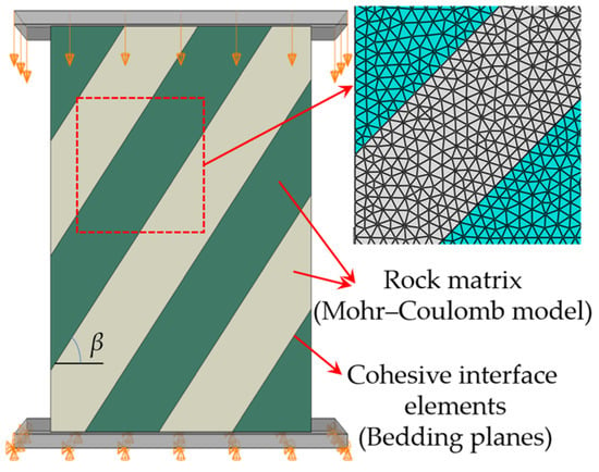
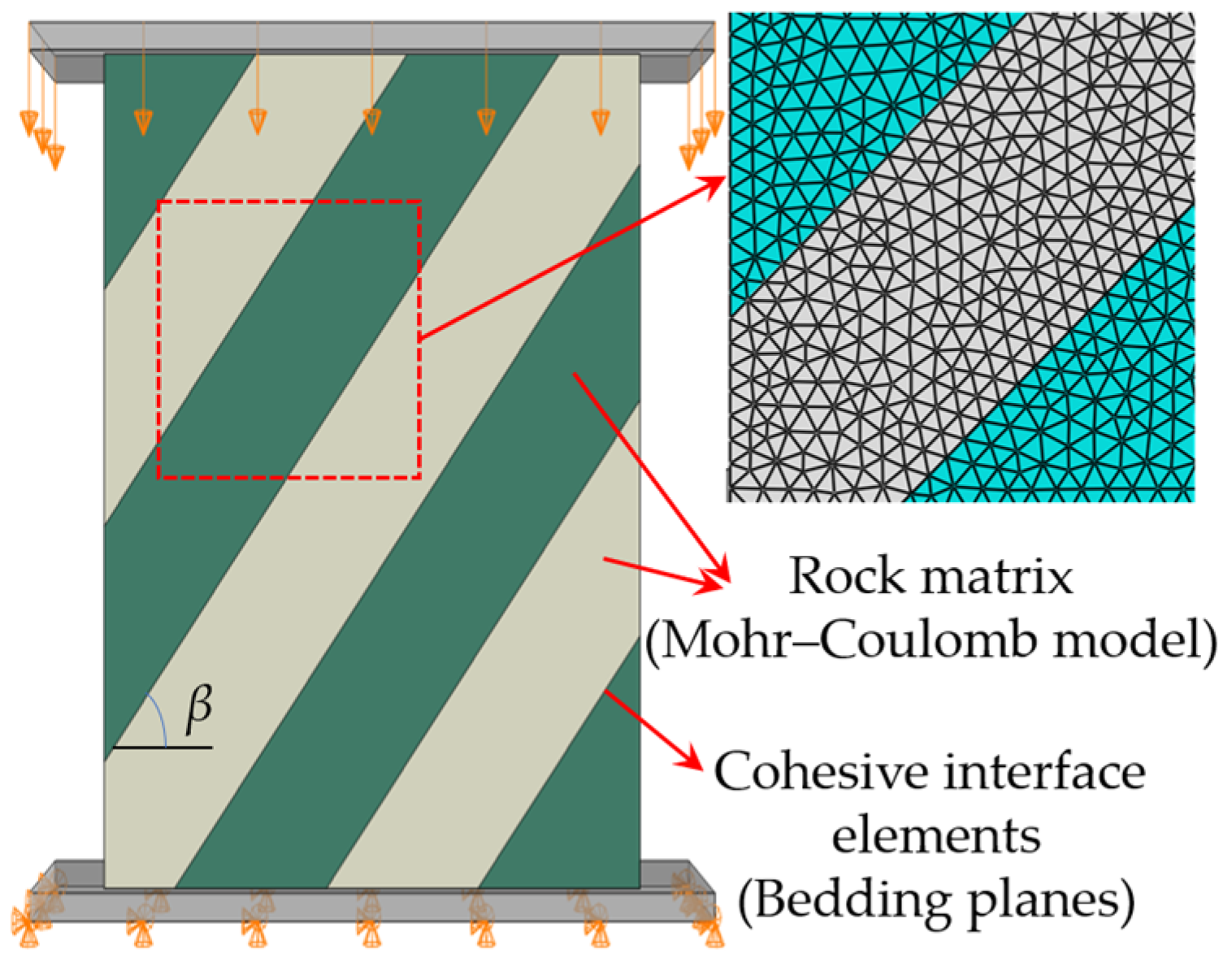
To validate the capability of the developed FDEM model in characterizing the mechanical response and failure mechanisms of stratified rock masses, typical carbonaceous slate from a specific section of the Muzhailing Tunnel was selected for laboratory uniaxial compression testing. Based on established physical experimental results [25], a numerical model replicating the specimen geometry, bedding architecture, and boundary conditions was constructed. By comparing the simulated and experimental results across various bedding dip angles, the fidelity of the model in reproducing stress–strain responses and interlayer damage evolution was systematically evaluated.
Specifically, the cylindrical carbonaceous slate model was built in Abaqus/Explicit (Version 2022) with parallel bedding interfaces spaced at intervals ( and ) and discretized with a characteristic element size of . Based on calibration against the laboratory tests of Hu et al. [25], the slate matrix was assigned , , , , and , whereas the zero-thickness cohesive bedding interfaces were assigned , , , , , , and . During the loading step, the bottom rigid platen was vertically fixed, and a constant quasi-static downward velocity of was applied to the top rigid platen.
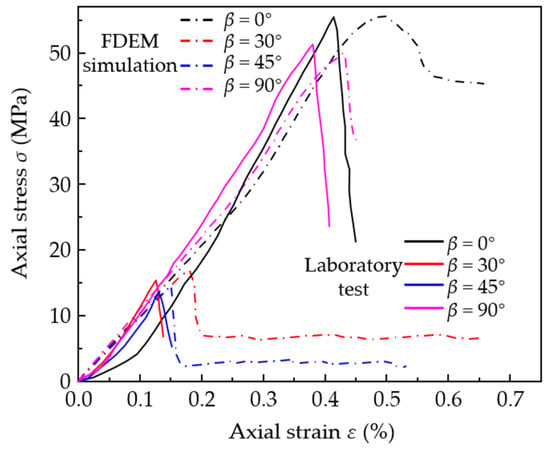
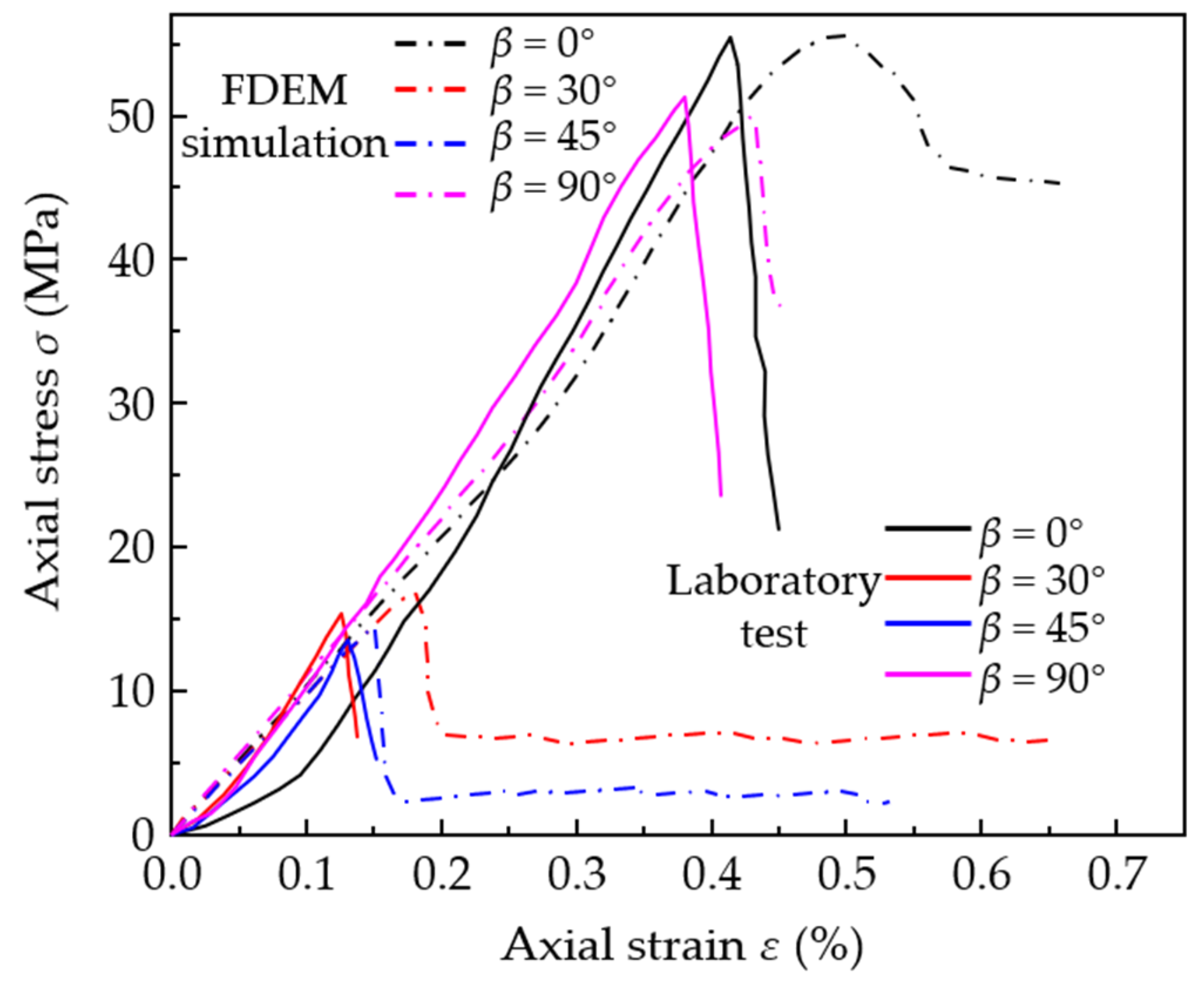
Specifically, the experimental curves at and were used to calibrate the matrix and interface parameters, respectively, while and served to validate the model across intermediate shear and axial splitting modes. As shown in Figure 4, the simulations capture the linear elastic slope (with tangent modulus deviations of ) and the U-shaped peak strength anisotropy. It should be noted, however, that because initial micro-fissure closure and matrix strain-softening are not included in the ideal elastoplastic Mohr–Coulomb matrix model, the simulations omit the initial concave compaction stage (), resulting in slightly smaller peak strains and higher post-peak residual strengths (especially in matrix-dominated cases at and ) compared to the brittle physical tests. Nevertheless, the model reliably captures the peak strength anisotropy and macroscopic failure mode transitions.
Figure 4.
Comparison of stress–strain responses between physical experiments and FDEM simulations for carbonaceous slate with different bedding inclinations.
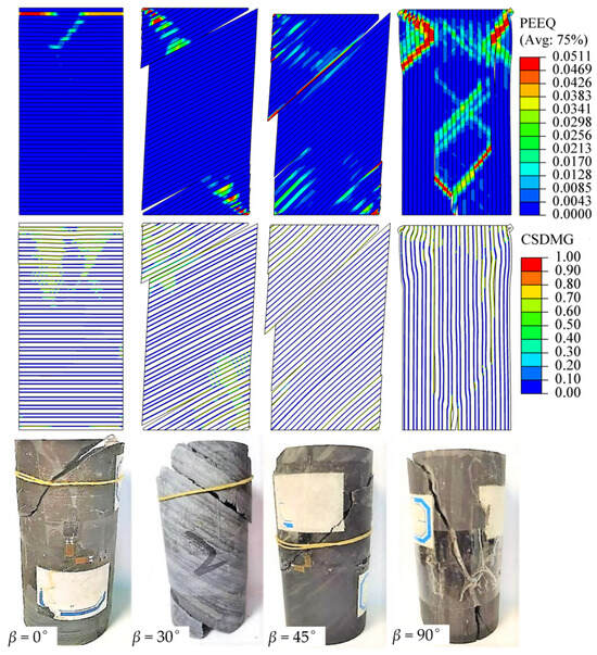
Nevertheless, the macroscopic stress–strain relationships and peak strengths alone are insufficient to verify whether the numerical model accurately reproduces microcrack initiation, fracture propagation paths, and structural-plane-dominated failure modes in highly anisotropic rock masses. Consequently, the physical failure patterns of carbonaceous slate specimens obtained from uniaxial compression tests by Hu et al. [25] were introduced as a physical benchmark. A systematic comparative analysis was conducted between the experimentally observed macroscopic fracture modes and the FDEM-simulated contours across different bedding inclinations (, and ), thereby comprehensively evaluating the fidelity of the model in capturing the progressive, anisotropic fracturing process (Figure 5).
Figure 5.
Experimental and FDEM-simulated failure evolution of carbonaceous slate with different bedding inclinations under uniaxial compression.
Figure 5 compares the simulated equivalent plastic strain (PEEQ) within the matrix and the cohesive damage variable () along bedding planes with the experimentally observed macroscopic failure patterns. The FDEM model reproduces the orientation-dependent transition of failure modes with high fidelity:
- (1)
- At , high normal compressive stress clamps the sub-horizontal interfaces; failure is dominated by conjugate compressive-shear bands traversing the intact matrix (elevated PEEQ), while interface damage () remains sparse and localized.
- (2)
- At and , the failure mode shifts to pronounced structural-plane dominance. As the bedding planes closely align with the maximum shear stress trajectory, rapidly reaches 1.0, forming a through-going debonded slip surface with localized matrix yielding flanking the interface, which captures the sharp drop in peak strength.
- (3)
- At , lateral Poisson’s expansion upon axial compression drives continuous tensile debonding along vertical interfaces (), triggering classic axial splitting accompanied by localized buckling of detached rock slabs.
Overall, the FDEM simulations successfully capture the cross-scale progressive failure process of carbonaceous slate, wherein intact matrix shear yielding (PEEQ) and interfacial debonding/slip () interact cyclically to dictate macroscopic collapse. This verified fidelity confirms that the proposed numerical framework accurately reflects both continuous matrix plasticization and discontinuous joint degradation, providing a reliable constitutive and structural foundation for extending the analysis to engineering-scale tunnel simulations in the subsequent section.
4. Bedding Dip Angle Effect on Asymmetric Deformation and Failure in Soft-Hard Interbedded Surrounding Rock
4.1. FDEM Model and Computational Schemes for the K1+140 Section
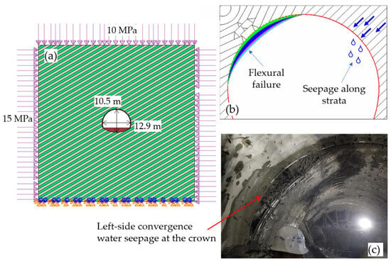
To systematically investigate the controlling role of the bedding dip angle on the asymmetric deformation and localized failure of tunnels in soft-hard interbedded ground, a two-dimensional FDEM numerical model was established based on section K1+140 of the No. 3 inclined shaft in the Muzhailing Tunnel (Figure 6a). This section has a maximum burial depth of approximately 455 m, with the surrounding rock mass primarily composed of alternating sequences of incompetent carbonaceous phyllite and competent sandy slate, exhibiting well-developed stratified structures. Following excavation, the surrounding rock exhibited pronounced directional failure characteristics: one side was dominated by flexural bending and compressive squeezing extrusion, whereas the opposite side was prone to interlayer shear sliding, tensile opening, and localized groundwater seepage, accompanied by substantial asymmetric convergence (Figure 6b,c). In-situ stress testing indicates that horizontal tectonic stresses prevail in this section, providing representative engineering conditions for evaluating the bedding dip angle effect in soft-hard interbedded ground under high geostresses.
Figure 6.
Field failure characteristics and FDEM numerical model of the No. 3 inclined shaft of the Muzhailing Tunnel: (a) FDEM numerical model; (b) Typical asymmetric failure modes; (c) Field photograph of large deformation.
Numerical calculations were performed using the established and verified FDEM framework described in Section 3. The matrices of both the soft carbonaceous phyllite and the hard sandy slate were simulated using the Mohr–Coulomb elastoplastic model. Zero-thickness cohesive elements were pre-inserted along the soft-hard lithological interfaces to explicitly simulate the coupled progression of matrix plastic yielding, tensile delamination, shear slip, and cohesive bonding degradation during excavation. To ensure strict geometric consistency across models with varying bedding dip angles—including overall dimensions, individual layer thicknesses, and numerical discretization schemes—a Python-based parametric modeling script was developed within the Abaqus/Explicit environment to automate the batch generation of models with different bedding orientations.
As depicted in Figure 6a, the computational domain has dimensions of , with the tunnel opening situated at the model center. The external boundaries are placed beyond three times the tunnel span from the opening perimeter to minimize boundary reflection and edge effects on the excavation response. Based on the design cross-section of the No. 3 inclined shaft, the tunnel cross-section features an excavation span of and a total height of from the invert base to the crown. The domain was discretized using a graded mesh strategy, featuring a refined characteristic element size of approximately in the near-field zone surrounding the tunnel perimeter; preliminary mesh sensitivity checks confirmed that further mesh refinement yielded negligible variations (<2%) in radial convergence and asymmetry indices. A two-dimensional plane-strain condition was assumed. By projecting the measured three-dimensional in-situ principal stresses ( intersecting the shaft axis at , Section 2.2) onto the two-dimensional cross-sectional plane perpendicular to the tunnel axis, representative in-plane initial stresses of (horizontal) and (vertical, ) were obtained. The numerical simulation was executed in two sequential steps: first, in the geostatic initialization step, the initial stresses were equilibrated across the unexcavated domain and all resulting nodal displacements were reset to zero; second, in the excavation step, the rock elements inside the tunnel profile were deactivated while simultaneously activating the -thick shotcrete primary lining—modeled with linear elastic CPE4R solid elements bonded to the rock boundary via a tied constraint—over a smooth unloading amplitude. Thus, all reported displacements strictly represent excavation-induced deformations under immediate support installation.
Although individual slate foliations in the field are thick (Section 2.1), they occur macroscopically as alternating meter-scale lithological packages. To ensure computational tractability across the FDEM domain while maintaining a small layer-thickness-to-span ratio () representative of stratified ground [34,37], the layer thickness of both soft and hard strata was uniformly set to to isolate the independent controlling role of the bedding dip angle. In the Python (Version 3.8) parametric script, the rotation pivot of the alternating strata was fixed strictly at the geometric center of the tunnel cross-section so that an identical soft–hard layer sequence intersected the opening center as the bedding orientation was rotated, ensuring strict comparability across all cases. While thinner individual beds or varying soft-to-hard thickness ratios would reduce single-layer flexural rigidity and increase absolute convergence magnitudes [37], the relative dip-angle sensitivity trend and tangency-driven migration mechanism remain governed by the dip angle . All other parameters—including the mechanical properties of the two rock matrices, cohesive interface properties, initial in-situ stresses, tunnel geometry, and support conditions—were held constant, with the bedding dip angle () serving as the sole variable. Seven representative scenarios were investigated: and , fully covering structural transitions from horizontal to sub-vertical strata. The physicochemical and mechanical parameters of the rock matrices and primary support are summarized in Table 1, and the cohesive interface parameters are listed in Table 2.
Table 2.
Cohesive parameters of bedding interfaces.
The mechanical parameters of the intact rock matrices were determined based on in-situ tests and established engineering studies from the Muzhailing Tunnel, while the cohesive interface parameters were calibrated against laboratory test data and the numerical benchmark established in Section 3. During the numerical simulations, peripheral displacements around the tunnel, equivalent plastic strain (PEEQ) within the rock matrices, and the interface cohesive damage variable (CSDMG) were systematically extracted. These metrics respectively characterize macroscopic convergence, matrix plastic shear yielding, and discontinuous interlayer fracturing. Consequently, a comprehensive multi-scale correlation linking bedding dip angle, peripheral displacement, matrix plastic yielding, and interlayer interface failure was established, providing a rigorous quantitative foundation for deciphering the asymmetric deformation mechanisms and failure modes in soft-hard interbedded surrounding rock.
4.2. Engineering Validation and Macroscopic Asymmetric Deformation Response
4.2.1. Engineering Benchmark Comparison and Model Applicability Evaluation
The numerical model adopts a two-dimensional plane-strain assumption with an idealized single-step full-face excavation and immediate lining installation. In reality, section K1+140 was constructed via the three-bench method, where convergence reached 43 cm over nearly 20 days (Figure 6c), driven by multi-stage excavation disturbance, 3D face advancement, long-term rock mass rheology, and groundwater softening of the carbonaceous phyllite. Because the idealized simulation inherently excludes these cumulative time-dependent processes, direct mechanical comparison of absolute displacements is physically unsuitable. Instead, the model’s engineering validity is substantiated across two key dimensions:
- (1)
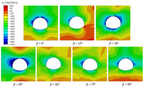
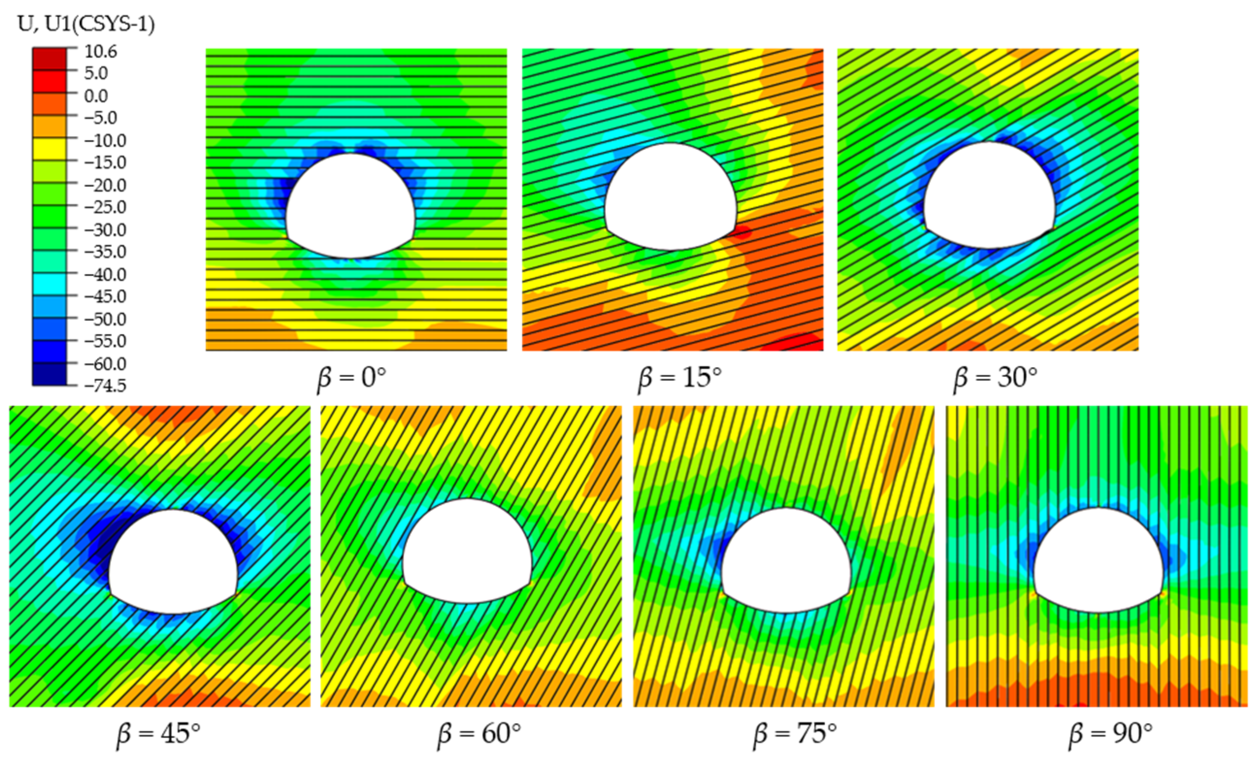
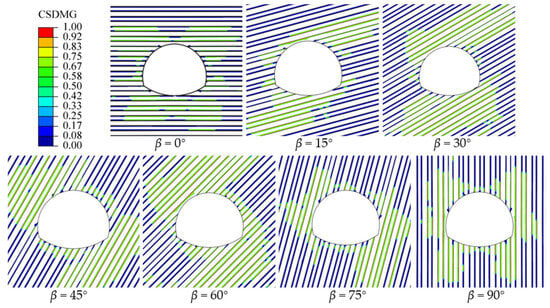
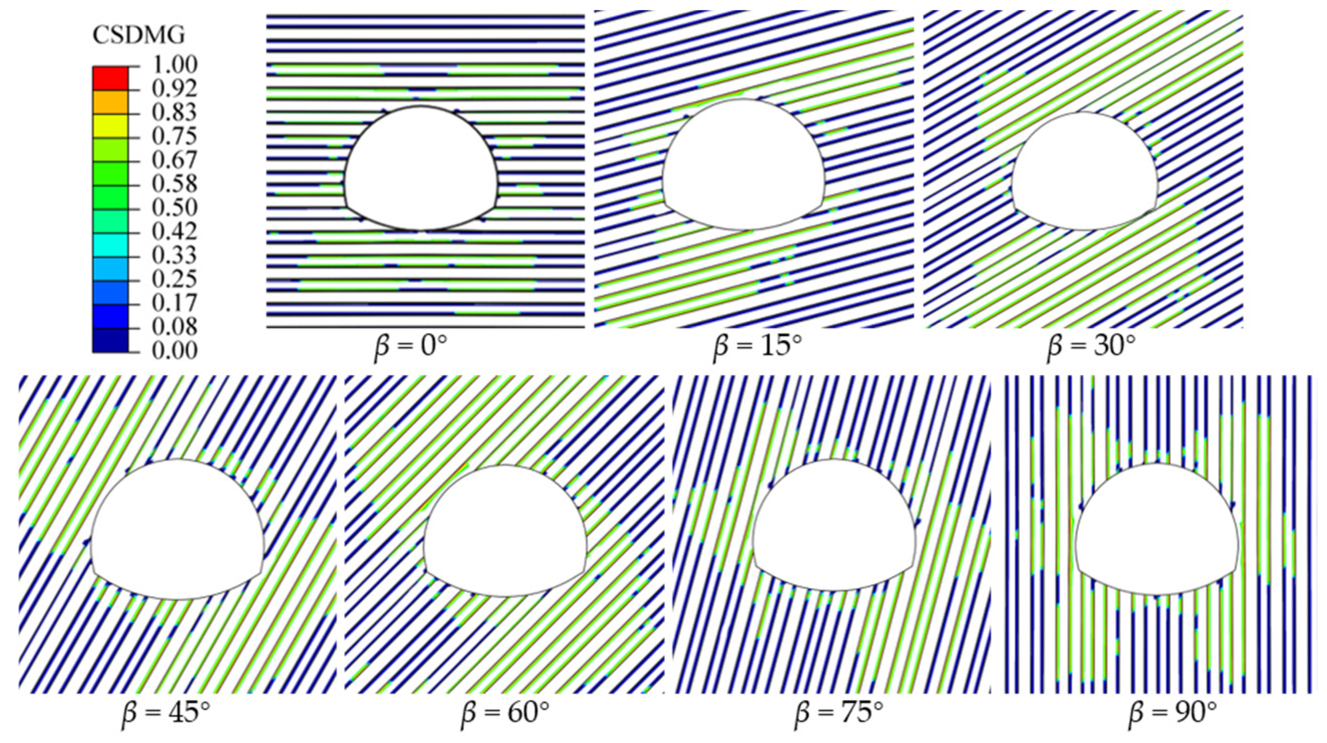
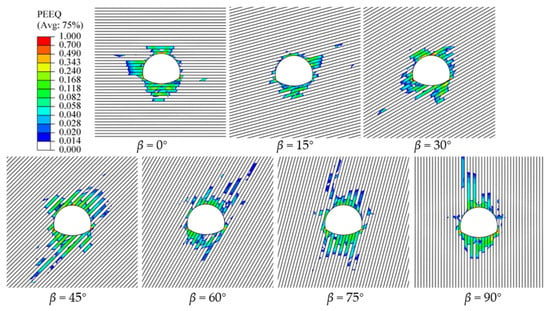
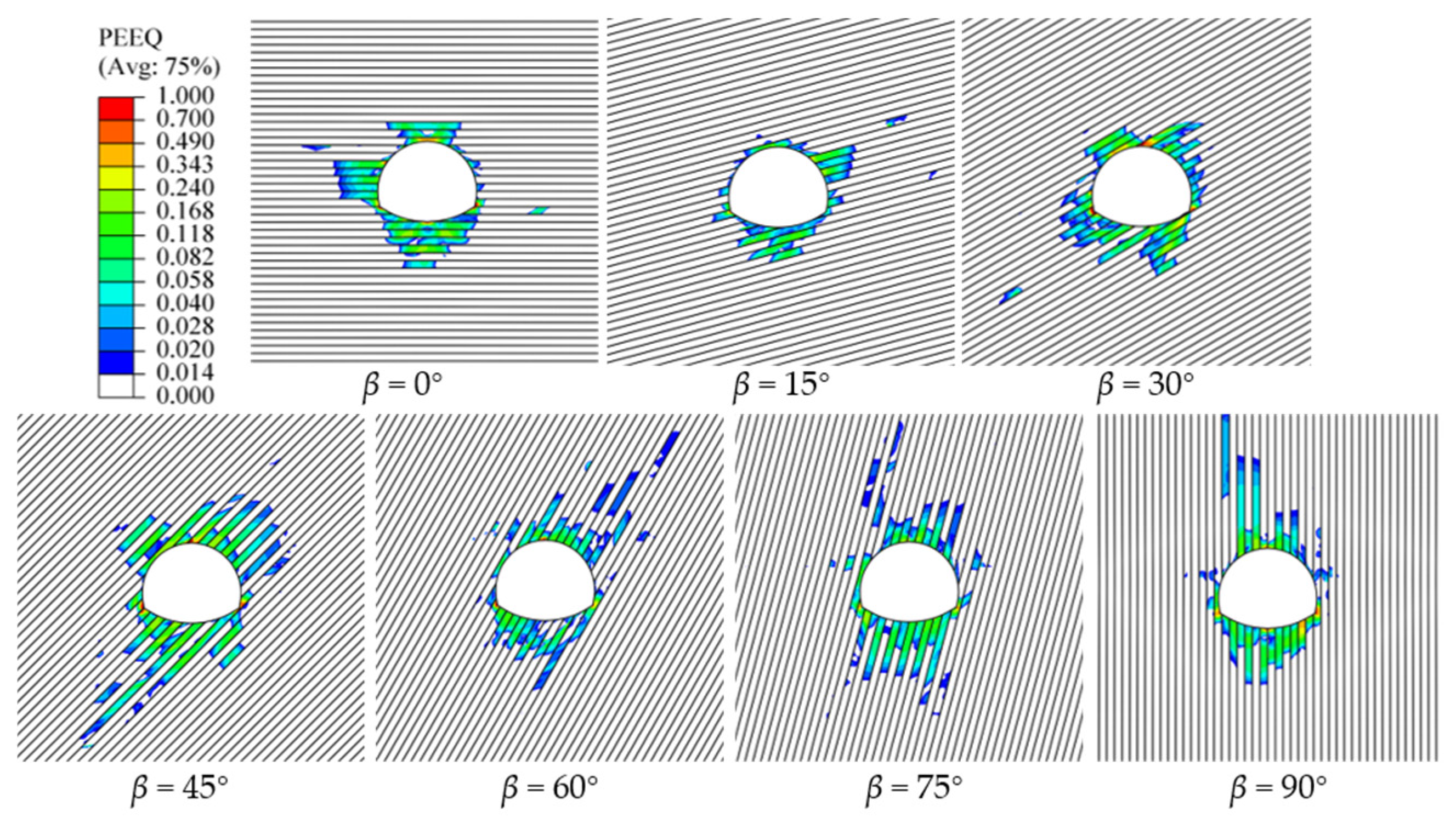
- Failure mode and spatial pattern: Field surveys at section K1+140 (–) identified severe asymmetric damage: flexural squeezing on one side versus interlayer shear slip and joint seepage on the other (Figure 6b,c). The simulation reproduces these localized features with high fidelity, showing maximum convergence at the left shoulder/sidewall (Figure 7), paired diagonal cohesive damage (Figure 8), and plastic yielding biased toward the upper-left boundary (Figure 9).Figure 7. Radial displacement distributions of tunnel surrounding rock at different bedding dip angles.Figure 8. Cohesive damage distributions along bedding interfaces at different bedding dip angles.Figure 9. Equivalent plastic strain distributions in the rock matrix at different bedding dip angles.
- (2)
- Dip-angle sensitivity window: Field monitoring and previous numerical studies at the Muzhailing Tunnel confirmed that surrounding-rock deformation peaks within a bedding dip range of –. Consistently, the simulated radial convergence reaches its global maximum of 74.47 mm at , capturing this critical amplification window.
Consequently, having been validated against laboratory tests (Section 3.4) and corroborated by field failure modes and sensitivity trends, the model is soundly applicable for investigating the dip-angle-dependent deformation mechanisms. Specifically, immediate lining activation in the 2D full-face model constrains radial displacement early ( at ), whereas in actual three-bench tunneling, pre-support stress release during 3D face advancement, staged bench disturbances, and 20-day creep substantially amplify the absolute convergence (). Nevertheless, because 3D face advancement primarily scales the radial unloading ratio without altering the in-plane geometric angle between the principal stresses and the bedding planes, it does not shift the boundaries of the critical amplification window, which is governed by the intrinsic stress–structure coupling in the cross-sectional plane.
4.2.2. Macroscopic Asymmetric Deformation Response
Figure 7 illustrates the radial displacement contours of the surrounding rock across – (negative values indicate inward convergence toward the opening void). At and , the rock mass preserves geometric symmetry relative to the tunnel axes, producing regular, symmetric displacement fields. In contrast, within –, inclined strata disrupt kinematic symmetry: the internal load-transfer paths are fundamentally reconfigured, causing maximum convergence zones to shift along the perimeter and inducing pronounced asymmetric deformation.
To quantitatively evaluate the governing effect of the bedding dip angle on deformation magnitude, asymmetry degree, and the migration of preferred deformation zones, radial convergence displacements were extracted along the excavation perimeter using a polar coordinate system (with the tunnel crown defined as and clockwise as positive). The maximum radial convergences in the left half-section (–) and right half-section (–)—denoted as and , alongside their corresponding polar angles and —were statistically determined. A dimensionless asymmetry index () was introduced to quantify the eccentric loading and deformation bias between the two sides:
where indicates that deformation in the left half-section dominates; denotes that the right half-section governs; and approaching zero indicates an increasingly symmetric deformation field. Formulated as a normalized bilateral contrast ratio [21,37], the dimensionless asymmetry index () in Equation (6) normalizes the difference between the left- and right-half maximum convergences by their sum, bounding within . Because dominant deformation zones migrate along the tunnel profile with , fixed monitoring points cannot capture the shifting hazard centers; thus, using the separate half-section maxima ( and ) directly quantifies the disparity between the most severe squeezing zones on opposite sides. It should be noted that because and occur at their respective peak angles ( and ) rather than strictly conjugate mirror points, evaluates bilateral peak-hazard bias rather than point-wise mirror asymmetry, and should be interpreted alongside and in Table 3. Synthesizing Figure 7 and Table 3, the following mechanical characteristics are identified:
Table 3.
Maximum radial convergence and asymmetry index of surrounding rock at different bedding dip angles.
- (1)
- Non-monotonic variation and moderate-dip amplification regime: The maximum radial convergence responds non-monotonically to strata inclination (Table 3). At , symmetric roof/floor bending yields (). As the strata incline, convergence first drops to at , then rebounds substantially across the moderate-dip interval of () to (, global peak)—representing a and amplification at relative to the adjacent () and () cases, respectively. Combined with the deepest interface damage (Figure 8) and plastic zone penetration (Figure 9) at , this confirms a pronounced moderate-dip amplification regime around , which aligns with the high-deformation zone reported in the Muzhailing Tunnel [7,21].
- (2)
- Structural asymmetry and decoupling of eccentric loading: Except at , maximum convergence across all inclined cases concentrates within the left half-section (). While symmetric orientations () maintain kinematic compatibility (), inclined bedding (–) triggers severe eccentric loading, with peaking at 0.153 for . Crucially, a distinct decoupling emerges between peak deformation magnitude and maximum structural asymmetry: while yields the highest absolute convergence, both sidewalls deform substantially, resulting in moderate eccentricity (); conversely, at , the sharp disparity between the left shoulder/sidewall (62.01 mm) and the right foot (45.57 mm) drives to its global maximum, manifesting severe unilateral squeezing.
- (3)
- Geometrically, for strata dipping from upper-right to lower-left at angle , the tangency points where bedding planes parallel the tunnel boundary rotate downward along the upper-left perimeter (, adjusted for horseshoe curvature) and toward the lower-right foot/invert (). This geometric trajectory directly governs the downward migration of () and in Table 3. As corroborated by the deformed layer profiles in Figure 7, the complete interface debonding () in Figure 8, and the localized plastic zones in Figure 9, rock layers at these tangent boundaries lose radial confinement under concentrated tangential compression (), undergoing interlayer separation and inward flexural deflection.
- (4)
- This shear-slip mechanism is directly evidenced by comparing Figure 7, Figure 8 and Figure 9 at : unlike the localized near-boundary buckling at other inclinations, Figure 8 exhibits long, straight, through-going interface debonding bands () extending deep into the rock mass along the planes at the right crown and lower-left sidewall, which reorient the peripheral displacement field (Figure 7) and drive the rightward convergence bias.
- (5)
- From the perspective of stress-tensor rotation, under the horizontal-dominated virgin stress field () and an interfacial friction coefficient of (), the theoretical Mohr–Coulomb critical slip angle relative to the horizontal major principal stress is , which lies adjacent to . Upon excavation, as the principal stress tensors rotate around the opening perimeter, the tangential major principal stress () intersects the bedding planes at the right crown () and lower-left sidewall () at an optimal slip angle of . This maximizes the resolved shear-to-normal stress ratio (), triggering deep, through-going interlayer shear slip (Figure 8). Consequently, this shear slip relieves tangential stress concentration at the left shoulder and redirects principal stress trajectories toward the right arch and lower-left wall, resulting in ().
In summary, macroscopic asymmetric deformation couples magnitude amplification with spatial eccentric migration. Consequently, evaluating surrounding-rock stability solely by total convergence is insufficient: support design within the – window must prioritize resistance against severe overall squeezing, whereas within the steep – range, measures must focus on unilateral eccentric pressure and localized shear kicking at the tunnel foot.
4.3. Bedding Interface Damage and Interlayer Slip Evolution
To evaluate structural-plane degradation around the tunnel, the cohesive damage variable () along bedding interfaces was extracted (Figure 8), where indicates complete loss of cohesive bonding and a transition to pure Coulomb frictional contact slip (). As illustrated in Figure 8, interface damage concentrates within the near-field relaxation zone, exhibiting pronounced dip-angle dependency across three distinct mechanical regimes:
- (1)
- Symmetric damage under orthogonal orientations ( and ). Interfacial failure strictly mirrors the tunnel geometry. Under horizontal strata (), intense tangential shearing induced by triggers localized shear damage along horizontal interfaces at the crown and invert, accompanied by discrete sidewall delaminations. Under sub-vertical strata (), lateral Poisson’s expansion upon sidewall unloading generates tensile stresses perpendicular to the strata, producing through-going axial splitting bands () parallel to the sidewalls.
- (2)
- Tangency-driven asymmetric deflection and spatial migration (–). Inclined strata break geometric symmetry, reconfiguring interface damage into paired diagonal conjugate bands. Driven by the rotation of the tangency point between the bedding planes and the excavation boundary, the dominant damage zones rotate counter-clockwise: concentrating along the upper-right shoulder and lower-left foot at , and shifting entirely to the upper-left shoulder and lower-right foot at –. Where strata are tangent to the perimeter, the release of normal stress () combined with elevated shear stress () promotes preferential debonding and slip-band coalescence.
- (3)
- Multi-layer slip coalescence at intermediate dips (–). Within this critical range, bedding orientations closely align with maximum shear stress trajectories. At , damage propagates deep into the rock mass in a stepped, through-going pattern (), providing the mesoscale structural origin for the global peak convergence (74.47 mm). At , extensive shear damage extends along the lower left sidewall, degrading local stiffness and explaining the rightward shift in peak convergence ().
- (4)
- Macro–meso decoupling and energy dissipation (β = 60°). Viewed from the energy balance of the model, the β = 60° configuration yields the smallest matrix plastic zone (Figure 9) and the lowest radial convergence (48.97 mm, Figure 7) among the inclinations examined, both falling below those of β = 45°; nevertheless, extensive through-going debonding bands (CSDMG = 1.0, Figure 8) develop along the steeply dipping weak bedding interfaces. This contrast demonstrates that boundary convergence does not scale monotonically with interface damage and reveals an intrinsic deformation-mode transition: a substantial portion of the excavation-induced strain energy is dissipated through frictional shear slip (interlayer shear dislocation) along the debonded planes, rather than through inward radial squeezing of the rock matrix. The resulting decoupling between the macroscopic boundary response and the mesoscopic internal damage implies that modest boundary displacements can mask severe internal structural degradation.
- (5)
- Engineering implications for potential seepage pathways. In field tunneling, completely debonded interfaces () undergoing normal separation or shear slip represent zones of structural loosening that may serve as potential preferential pathways for groundwater ingress, which qualitatively aligns with the localized fissure seepage observed on the sliding side at section K1+140 (Figure 6b,c). It must be emphasized, however, that because the present model does not include seepage analysis, an aperture–permeability relationship, or an interface shear-dilation law, only identifies the mechanical precursor of interface debonding; confirming actual permeable flow paths requires further coupled hydro-mechanical validation.
Furthermore, although groundwater softening is a known factor at the tunnel site (Section 2.1), the present model adopts baseline parameters without explicit pore pressure or moisture-dependent degradation functions. In practice, water infiltration along debonded interfaces would reduce the interfacial strength (), friction coefficient (), and phyllite matrix parameters (), which would lower the stress threshold for slip initiation, increase absolute convergence magnitudes, and broaden the critical dip-angle range susceptible to shear sliding.
4.4. Plastic Zone Evolution in the Rock Matrix
Figure 9 illustrates the spatial distributions of equivalent plastic strain (PEEQ) across various bedding dip angles, delineating regions of matrix shear yielding and crushing flow. The plastic zones exhibit pronounced lithological differentiation and structural-plane-guided features:
- (1)
- Lithological plastic differentiation (“soft-layer concentration and hard-layer shielding”). Plastic strain is sharply partitioned between alternating lithologies across all dip angles. Owing to its lower strength and stiffness (Table 1), the incompetent carbonaceous phyllite exhibits severe PEEQ accumulation and interlayer squeeze flow. In contrast, the competent sandy slate remains largely elastic at depth, acting as a flexural load-bearing skeleton with yielding restricted to the immediate excavation boundary. This stark property disparity generates severe shear stress jumps across lithological interfaces.
- (2)
- Dip-angle control over plastic morphology and peak penetration (). While symmetric orientations () yield mirror-symmetric plastic zones (crown/invert for ; sidewalls for ), inclined strata (–) reorient plastic bands into discrete strips dipping toward the upper-left shoulder. Consistent with macroscopic convergence (Figure 7), the plastic penetration depth varies non-monotonically, achieving its global maximum at . Here, the plastic zone daylights extensively at the left shoulder, directly underpinning the peak convergence (74.47 mm) observed within the critical – window.
- (3)
- Spatial-mechanical coupling between continuous matrix plastic yielding and discontinuous interface damage. It should be noted that within the present Mohr–Coulomb formulation, PEEQ strictly represents continuum plastic shear yielding of the rock matrix (without intralayer damage or strain softening), whereas damage and debonding () are restricted exclusively to the bedding interfaces. Synthesizing the post-excavation equilibrium distributions in Figure 7, Figure 8 and Figure 9 reveals a strong spatial-mechanical coupling between these two mechanisms: plastic shear yielding and squeeze flow within the weak carbonaceous phyllite layers (elevated PEEQ in Figure 9) induce incompatible deformation across the lithological boundaries, which intensifies interfacial stress concentrations and promotes cohesive bonding degradation ( in Figure 8) and interlayer slip. Conversely, interface debonding and slip eliminate shear stress transfer across the bedding planes, reducing the composite load-bearing capacity of the interbedded system and further ampliarifying plastic shear yielding within the rock matrices. This mutual mechanical reinforcement is most pronounced within the window, governing the severe asymmetric squeezing in deep interbedded ground.
5. Conclusions
An FDEM coupled numerical framework combining Mohr–Coulomb matrix plasticity and cohesive interface debonding was established to investigate the bedding dip angle effect (–) on asymmetric deformation in deep-buried soft-hard interbedded ground. Following specimen- and engineering-scale validations against the Muzhailing Tunnel, the main conclusions are drawn as follows:
- (1)
- Non-monotonic deformation amplification and decoupling of structural asymmetry: The maximum radial convergence responds non-monotonically to bedding dip, peaking at (74.47 mm)—a 52.1% amplification over the minimum at (48.97 mm)—defining a critical amplification window within –. While symmetric strata () yield near-zero asymmetry (), inclined strata induce severe eccentric loading. Crucially, a distinct decoupling exists between the global peak deformation magnitude () and the maximum structural asymmetry ( at ).
- (2)
- Tangency-driven spatial migration and localized shear-slip anomaly: Dominant deformation zones migrate systematically along the tunnel profile driven by geometric tangency between bedding planes and the excavation boundary, which concentrates circumferential compressive stresses and triggers flexural buckling. At , this tangency-governed trend is overridden because bedding alignment with the maximum shear stress trajectory triggers extensive interlayer shear slip, shifting peak convergence anomalously to the right side ().
- (3)
- Lithological plastic differentiation and macro-meso decoupling: Plastic strain concentrates almost exclusively within the incompetent carbonaceous phyllite as extrusion flow, whereas competent sandy slate serves as a flexural load-bearing skeleton. Crucially, boundary convergence decouples from internal structural damage: at , modest radial convergence masks extensive through-going interface damage (), where released strain energy is primarily dissipated via subsurface interlayer shear slip rather than radial squeezing.
- (4)
- Synergistic cross-scale mechanism and engineering implications for support: The asymmetric instability of interbedded ground is governed by the spatial-mechanical coupling between continuous matrix shear yielding and discontinuous interface slip. As an engineering implication of these deformation patterns, tunnel stability assessment should look beyond total convergence: the range suggests a need to resist severe quasi-symmetric squeezing, whereas the range points toward mitigating unilateral eccentric deformation and localized slip at the shoulder and foot. Because only a single baseline support configuration under dry conditions was simulated herein, specific support stiffness designs and asymmetric reinforcement layouts require further dedicated numerical and field validation. Future work incorporating coupled hydro-mechanical softening and moisture-dependent interface degradation is warranted to quantify how groundwater shifts these quantitative deformation thresholds.
Author Contributions
Conceptualization, X.L. and C.G.; methodology, X.L.; software, X.L. and Z.W.; validation, Z.W. and C.G.; formal analysis, X.L. and Y.L.; investigation, Y.L. and Z.W.; resources, C.G.; data curation, X.L. and Z.W.; writing—original draft preparation, X.L.; writing—review and editing, C.G. and Z.W.; visualization, C.G. and Z.W.; supervision, C.G.; project administration, X.L.; funding acquisition, X.L. All authors have read and agreed to the published version of the manuscript.
Funding
This research was funded by the Shanxi Provincial College Students’ Innovation and Entrepreneurship Training Program, grant number S202614527048, and the Scientific Research Startup Fund of Shanxi Institute of Technology, China, grant number 2024QD-24.
Data Availability Statement
The data that support the findings of this study are available within the manuscript.
Acknowledgments
GPT-6 Luna was used solely for English language polishing. The authors take full responsibility for the content of this publication.
Conflicts of Interest
The authors declare no conflicts of interest.
References
- Tian, S.M.; Wang, W.; Yang, C.Y.; Liu, C.; Wang, M.N.; Wang, K.J.; Ma, Z.F.; Lv, G. Development and prospect of railway tunnels in China in recent 40 years. Tunnel Constr. 2021, 41, 1903–1930. [Google Scholar]
- Liu, X.F.; Pan, P.Z.; Xu, D.P.; Zhou, Y.Y.; Wang, Z.F. Research progress of the large deformation of layered surrounding rock tunnel with high in situ stress. Chin. J. Undergr. Space Eng. 2024, 20, 1007–1020. [Google Scholar]
- Wagner, H. Deep mining: A rock engineering challenge. Rock Mech. Rock Eng. 2019, 52, 1417–1446. [Google Scholar] [CrossRef] [Scilit]
- Chen, Z.Q.; He, C.; Xu, G.W.; Ma, G.Y.; Wu, D. A case study on the asymmetric deformation characteristics and mechanical behavior of deep-buried tunnel in phyllite. Rock Mech. Rock Eng. 2019, 52, 4527–4545. [Google Scholar] [CrossRef] [Scilit]
- Chen, J.X.; Liu, W.W.; Chen, L.J.; Luo, Y.B.; Li, Y.; Gao, H.J.; Zhong, D.C. Failure mechanisms and modes of tunnels in monoclinic and soft-hard interbedded rocks: A case study. KSCE J. Civ. Eng. 2020, 24, 1357–1373. [Google Scholar] [CrossRef] [Scilit]
- Liu, X.Z.; Liu, F.; Song, K.Z. Mechanism analysis of tunnel collapse in a soft-hard interbedded surrounding rock mass: A case study of the Yangshan Tunnel in China. Eng. Fail. Anal. 2022, 138, 106304. [Google Scholar] [CrossRef] [Scilit]
- Sun, X.M.; Zhao, C.W.; Tao, Z.G.; Kang, H.W.; He, M.C. Failure mechanism and control technology of large deformation for Muzhailing Tunnel in stratified rock masses. Bull. Eng. Geol. Environ. 2021, 80, 4731–4750. [Google Scholar] [CrossRef] [Scilit]
- Liu, W.W.; Chen, J.X.; Luo, Y.B.; Chen, L.J.; Shi, Z.; Wu, Y.F. Deformation behaviors and mechanical mechanisms of double primary linings for large-span tunnels in squeezing rock: A case study. Rock Mech. Rock Eng. 2021, 54, 2291–2310. [Google Scholar] [CrossRef] [Scilit]
- Zhou, P.Y.; Song, Z.P.; Wang, J.B.; Zhang, Y.W.; Tian, X.X. Prediction method for ground surface settlement induced by bias tunnel based on stochastic medium theory. Chin. J. Geotech. Eng. 2025, 47, 589–598. [Google Scholar]
- Feng, X.T.; Guo, H.S.; Yang, C.X.; Li, S.J. In situ observation and evaluation of zonal disintegration affected by existing fractures in deep hard rock tunneling. Eng. Geol. 2018, 242, 1–11. [Google Scholar] [CrossRef] [Scilit]
- Amadei, B. Importance of anisotropy when estimating and measuring in situ stresses in rock. Int. J. Rock Mech. Min. Sci. Geomech. Abstr. 1996, 33, 293–325. [Google Scholar] [CrossRef] [Scilit]
- Sun, X.M.; Zhang, G.F.; Cai, F.; Yu, S.B. Asymmetric deformation mechanism within inclined rock strata induced by excavation in deep roadway and its controlling countermeasures. Chin. J. Rock Mech. Eng. 2009, 28, 1137–1143. [Google Scholar]
- Niandou, H.; Shao, J.F.; Henry, J.P.; Fourmaintraux, D. Laboratory investigation of the mechanical behaviour of Tournemire shale. Int. J. Rock Mech. Min. Sci. 1997, 34, 3–16. [Google Scholar] [CrossRef]
- Jaeger, J.C. Shear failure of anisotropic rocks. Geol. Mag. 1960, 97, 65–72. [Google Scholar] [CrossRef] [Scilit]
- Deng, H.F.; Wang, W.; Li, J.L.; Zhang, Y.C.; Zhang, X.J. Experimental study on anisotropic characteristics of bedded sandstone. Chin. J. Rock Mech. Eng. 2018, 37, 112–120. [Google Scholar]
- Tien, Y.M.; Kuo, M.C.; Juang, C.H. An experimental investigation of the failure mechanism of simulated transversely isotropic rocks. Int. J. Rock Mech. Min. Sci. 2006, 43, 1163–1181. [Google Scholar] [CrossRef] [Scilit]
- Zhou, Y.Y.; Liu, X.F.; Li, X.F. Progressive failure process of anisotropic rock: Insight from full-field strain evolution. KSCE J. Civ. Eng. 2022, 26, 460–471. [Google Scholar] [CrossRef] [Scilit]
- Cho, J.W.; Kim, H.; Jeon, S.; Min, K.B. Deformation and strength anisotropy of Asan gneiss, Boryeong shale, and Yeoncheon schist. Int. J. Rock Mech. Min. Sci. 2012, 50, 158–169. [Google Scholar] [CrossRef] [Scilit]
- Pu, S.J.; Wu, R.Q.; Wu, S.C.; Cheng, H.Y.; Cao, L.; Ren, Z.J. Analysis of deformation characteristics and failure mechanism of interbedded surrounding rock tunnels based on principal stress difference. Int. J. Geomech. 2024, 24, 04024197. [Google Scholar] [CrossRef] [Scilit]
- Han, W.G.; Cui, Z.D.; Tu, X.B.; Jin, Y.J.; Wang, Y.B. Response characteristics of different bedding plane angles to deformation of surrounding rock in layered rock tunnel. J. Eng. Geol. 2021, 29, 1267–1275. [Google Scholar]
- Zhang, L.X.; Chen, L.J.; Chen, J.X.; Luo, Y.B.; Guo, H.J.; Zhai, Y.; Wang, P.K. Load calculation method for deep-buried layered soft rock tunnel based on back-analysis of structural deformation. Symmetry 2024, 16, 383. [Google Scholar] [CrossRef] [Scilit]
- Fortsakis, P.; Nikas, K.; Marinos, V.; Marinos, P. Anisotropic behaviour of stratified rock masses in tunnelling. Eng. Geol. 2012, 141–142, 74–83. [Google Scholar] [CrossRef] [Scilit]
- Do, N.A.; Dias, D.; Dinh, V.D.; Tran, T.T.; Dao, V.C.; Dao, V.D.; Nguyen, P.N. Behavior of noncircular tunnels excavated in stratified rock masses—Case of underground coal mines. J. Rock Mech. Geotech. Eng. 2019, 11, 99–110. [Google Scholar] [CrossRef] [Scilit]
- Huang, F.; Zhu, H.H.; Xu, Q.W.; Cai, Y.C.; Zhuang, X.Y. The effect of weak interlayer on the failure pattern of rock mass around tunnel—Scaled model tests and numerical analysis. Tunn. Undergr. Space Technol. 2013, 35, 207–218. [Google Scholar] [CrossRef] [Scilit]
- Hu, T.T.; Zhang, Z.H.; Wang, D. Anisotropic mechanical characteristics of carbonaceous slate under conventional compression. J. Chang’an Univ. (Nat. Sci. Ed.) 2024, 44, 92–102. [Google Scholar]
- Liu, X.F.; Pan, P.Z.; Wang, Z.F.; Zhou, Y.Y.; Xu, D.P. A three-dimensional transversely isotropic equivalent continuum model for layered rock and numerical implementation. Int. J. Rock Mech. Min. Sci. 2024, 175, 105661. [Google Scholar] [CrossRef] [Scilit]
- Mas Ivars, D.; Pierce, M.E.; Darcel, C.; Reyes-Montes, J.; Potyondy, D.O.; Young, R.P.; Cundall, P.A. The synthetic rock mass approach for jointed rock mass modelling. Int. J. Rock Mech. Min. Sci. 2011, 48, 219–244. [Google Scholar] [CrossRef] [Scilit]
- Bhasin, R.; Høeg, K. Numerical modelling of block size effects and influence of joint properties in multiply jointed rock. Tunn. Undergr. Space Technol. 1998, 13, 181–188. [Google Scholar] [CrossRef] [Scilit]
- Jia, P.; Tang, C.A. Numerical study on failure mechanism of tunnel in jointed rock mass. Tunn. Undergr. Space Technol. 2008, 23, 500–507. [Google Scholar] [CrossRef] [Scilit]
- Munjiza, A.; Owen, D.R.J.; Bicanic, N. A combined finite-discrete element method in transient dynamics of fracturing solids. Eng. Comput. 1995, 12, 145–174. [Google Scholar] [CrossRef] [Scilit]
- Lisjak, A.; Grasselli, G. A review of discrete modeling techniques for fracturing processes in discontinuous rock masses. J. Rock Mech. Geotech. Eng. 2014, 6, 301–314. [Google Scholar] [CrossRef] [Scilit]
- Lisjak, A.; Grasselli, G.; Vietor, T. Continuum–discontinuum analysis of failure mechanisms around unsupported circular excavations in anisotropic clay shales. Int. J. Rock Mech. Min. Sci. 2014, 65, 96–115. [Google Scholar] [CrossRef] [Scilit]
- Hamdi, P.; Stead, D.; Elmo, D. Damage characterization during laboratory strength testing: A 3D-finite-discrete element approach. Comput. Geotech. 2014, 60, 33–46. [Google Scholar] [CrossRef] [Scilit]
- Deng, P.H.; Liu, Q.S.; Huang, X.; Pan, Y.C.; Wu, J. FDEM numerical modeling of failure mechanisms of anisotropic rock masses around deep tunnels. Comput. Geotech. 2022, 142, 104535. [Google Scholar] [CrossRef] [Scilit]
- Liu, P.; Liu, Q.S.; Deng, P.H.; Bo, Y.; Xie, X.Q. A novel mixed-mode power exponent cohesive zone model for FDEM and its application to tunnel excavation in the layered rock mass. Rock Mech. Rock Eng. 2024, 57, 1219–1243. [Google Scholar] [CrossRef] [Scilit]
- Guo, H.; Yan, C.Z.; Zhang, G.H.; Xu, R.; Wang, T.; Jiao, Y.Y. Mechanical analysis of toppling failure using FDEM: A case study for soft-hard interbedded anti-dip rock slope. Comput. Geotech. 2024, 165, 105883. [Google Scholar] [CrossRef] [Scilit]
- Hu, Y.K.; Yan, C.Z.; Jiao, Y.Y.; Wang, L.; Jia, Y.F.; Wang, Y.N. Analysis and countermeasures of asymmetric failure in layered surrounding rock tunnels based on FDEM: A case study. Eng. Fail. Anal. 2025, 167, 109049. [Google Scholar] [CrossRef] [Scilit]
- Dugdale, D.S. Yielding of steel sheets containing slits. J. Mech. Phys. Solids 1960, 8, 100–104. [Google Scholar] [CrossRef] [Scilit]
- Barenblatt, G.I. The mathematical theory of equilibrium cracks in brittle fracture. Adv. Appl. Mech. 1962, 7, 55–129. [Google Scholar] [CrossRef] [Scilit]
- Turon, A.; Camanho, P.P.; Costa, J.; Dávila, C.G. A damage model for the simulation of delamination in advanced composites under variable-mode loading. Mech. Mater. 2006, 38, 1072–1089. [Google Scholar] [CrossRef] [Scilit]
- Camanho, P.P.; Dávila, C.G.; de Moura, M.F. Numerical simulation of mixed-mode progressive delamination in composite materials. J. Compos. Mater. 2003, 37, 1415–1438. [Google Scholar] [CrossRef] [Scilit]
- Benzeggagh, M.L.; Kenane, M. Measurement of mixed-mode delamination fracture toughness of unidirectional glass/epoxy composites with mixed-mode bending apparatus. Compos. Sci. Technol. 1996, 56, 439–449. [Google Scholar] [CrossRef] [Scilit]
- Jaeger, J.C.; Cook, N.G.W.; Zimmerman, R.W. Fundamentals of Rock Mechanics, 4th ed.; Blackwell Publishing: Malden, MA, USA, 2007. [Google Scholar]
- Menétrey, P.; Willam, K.J. Triaxial failure criterion for concrete and its generalization. ACI Struct. J. 1995, 92, 311–318. [Google Scholar] [CrossRef] [Scilit]
- Dassault Systèmes. Abaqus 2022 Theory Guide; Simulia Corp.: Providence, RI, USA, 2022. [Google Scholar]

Disclaimer/Publisher’s Note: The statements, opinions and data contained in all publications are solely those of the individual author(s) and contributor(s) and not of MDPI and/or the editor(s). MDPI and/or the editor(s) disclaim responsibility for any injury to people or property resulting from any ideas, methods, instructions or products referred to in the content. |
© 2026 by the authors. Licensee MDPI, Basel, Switzerland. This article is an open access article distributed under the terms and conditions of the Creative Commons Attribution (CC BY) license.