


Abstract
Oblique inflow breaks the nominal rotational periodicity of a geometrically symmetric propeller by introducing an azimuth-dependent velocity component across the rotor disk. This study develops a transparent reduced order blade element/momentum framework to examine the resulting once-per-revolution aerodynamic loading of a representative two-bladed small UAV propeller. The formulation combines blade element aerodynamics, momentum-based induction, Fourier decomposition, and advancing–retreating blade diagnostics over moderate oblique inflow conditions. Particular attention is given to distinguishing quantities that arise directly from the assumed harmonic structure from quantities that provide independent aerodynamic information. A first-order analytical expansion shows that, for small in-plane velocity, the normalized first-harmonic loading scales approximately with the in-plane velocity ratio and therefore with J sin(α), consistent with the numerical model. The analysis additionally reports the absolute first-harmonic load amplitude, spanwise development of the asymmetry, cross-plane hub load components, circulation imbalance, and sensitivity to aerodynamic model assumptions. Published axial and non-axial propeller data are used to establish the range over which the reduced order trends can be interpreted. The results indicate that advance ratio and inflow angle govern the modeled cyclic asymmetry, whereas quantitative magnitudes remain sensitive to sectional aerodynamic assumptions and induced flow representation. The framework is therefore intended as a computationally inexpensive screening and interpretation tool for oblique inflow symmetry breaking rather than as a substitute for phase-resolved CFD or experimental measurements.
1. Introduction
Small multirotor aircraft rarely operate under perfect axial inflow. Forward translation, attitude changes, maneuvers, and ambient disturbances introduce velocity components both normal and parallel to the rotor disk. A blade therefore encounters a periodic variation in relative speed and effective incidence during each revolution. The disk-averaged thrust can remain smooth, while the individual blades experience a pronounced once-per-revolution load, producing pitch/yaw moments and a skewed wake. These effects are directly relevant to the concept of symmetry because the external flow selects a preferred direction even though the rotor geometry remains rotationally invariant.
Low-Reynolds-number propeller performance is strongly dependent on operating point and is difficult to extrapolate with high-Reynolds-number assumptions [1,2,3]. Theys et al. [4] showed that blade element/momentum and vortex lattice approaches can reproduce the principal trends of small propeller forces in oblique flow, although their quantitative accuracy decreases as non-axiality increases. Serrano et al. [5] experimentally observed that thrust and non-zero pitch/yaw moments increase with disk angle of attack because of advancing–retreating blade differences. Cerny and Breitsamter [6,7] similarly documented non-axial load changes and altered wake organization, while more recent small-drone measurements confirm that forward flight modifies both integral loads and the induced flow [8].
These findings motivate a reduced order analysis that is transparent about its assumptions. High-fidelity CFD can resolve viscous and three-dimensional wake physics but is computationally expensive, while a blade element/momentum model can rapidly evaluate a controlled operating matrix and expose the mathematical origin of the first azimuthal harmonic. McCrink and Gregory [3] demonstrated the usefulness of corrected blade element momentum models for low-Reynolds-number electric propulsion systems. For propellers at incidence, Theys et al. [4] and Rubin and Zhao [9] showed that momentum-based treatments remain valuable for trend prediction when the limits of the model are respected.
This paper intentionally excludes acoustic metrics and multi-objective noise ranking. Its purpose is to quantify flow-induced departures from the nominal π-periodic state. A baseline geometry is compared with a 10° symmetry-preserving outer-span swept variant (SLE). The swept case is selected because its macroscopic planform change can be represented explicitly in a reduced order aerodynamic model; trailing edge micro-serrations are not modeled here because their viscous effect cannot be resolved credibly without higher fidelity flow information.
The aerodynamic consequences of propeller incidence and yaw are not new. Classical analyses by Ribner [10] and de Young [11] established asymmetric propeller forces and moments under inclined inflow, while more recent actuator disk, blade element, experimental, and CFD studies have extended these concepts to small propellers and unmanned aircraft operating conditions. Accordingly, the novelty claimed here does not reside in identifying advancing–retreating blade asymmetry itself, nor in proposing a fundamentally new momentum theory. Instead, the contribution is a compact symmetry-oriented diagnostic framework that (i) connects the first azimuthal loading harmonic to the nominal π-periodic state of a two-bladed rotor; (ii) separates normalized harmonic content from its absolute load amplitude; (iii) relates the first-order asymmetry source term to its radial loading contribution; and (iv) quantifies how aerodynamic model assumptions affect the resulting symmetry-breaking indicators. The framework is intended for rapid interpretation and operating point screening prior to higher fidelity investigations.
2. Symmetry Framework
2.1. Rotational Symmetry and External Symmetry Breaking
For a geometrically balanced B-bladed rotor in uniform axial inflow, the phase-averaged blade state repeats after a rotation 2π/B. For B = 2, the nominal blade-to-blade state is π-periodic. Oblique inflow introduces a fixed in-plane velocity component and therefore selects a preferred disk direction. The geometry remains exactly symmetric, but the aerodynamic state is no longer invariant under a π rotation at a fixed instant.
The loss of the nominal π-periodic blade state is characterized primarily through the first azimuthal loading harmonic. A half-turn error Eπ is retained only as a symmetry space representation of the same departure rather than as an independent aerodynamic metric. For a purely sinusoidal blade load history, Eπ is analytically related to the normalized first-harmonic amplitude; departures from this relation would therefore indicate higher harmonic or non-sinusoidal loading content.
2.2. Geometric Cases
The baseline is a two-bladed 0.254 m diameter rotor with a nominal pitch of 0.114 m. The active reduced order blade begins at r/R = 0.28. The chord law is reconstructed from three reported geometric anchors: 18 mm at the active root, a maximum chord c/R = 0.18 at r/R = 0.75, and an 8 mm tip chord. The local geometric pitch angle follows the constant pitch helical relation . This representation is a reduced order surrogate rather than an exact reconstruction of the CAD surface.
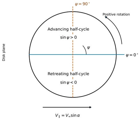
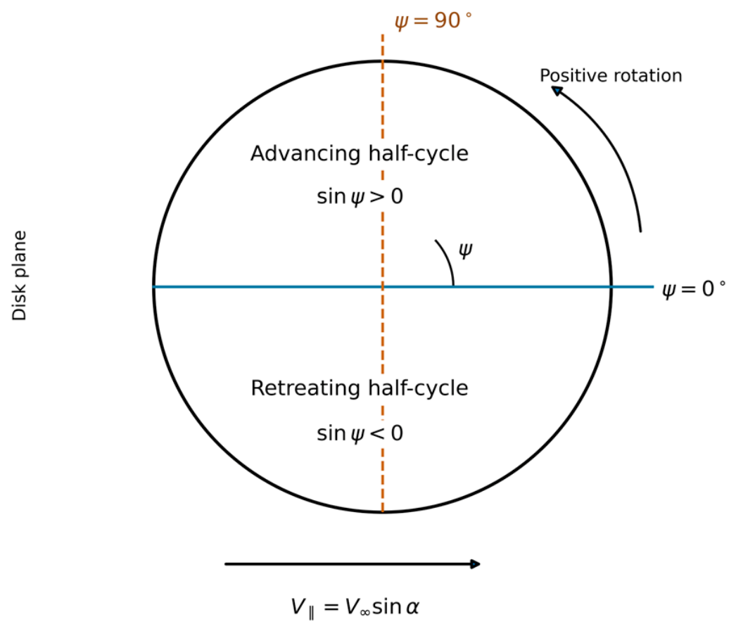
The SLE variant applies 10° of sweep over the outer 30% of radius while preserving the same diameter, blade count, pitch law, and chord magnitude. At reduced order, the large-scale effect of sweep is represented with a normal flow correction CL,SLE = CL cos2(Λ) in the swept region. No empirical acoustic or serration correction is introduced. Table 1 summarizes the geometric definitions, and Figure 1 defines the coordinate convention used throughout the model.
Table 1.
Geometric definitions used in the reduced order model.
Figure 1.
Coordinate convention for the reduced order oblique inflow model, viewed along the shaft axis. The solid blue horizontal axis defines ψ = 0° toward the right, and the orange dashed vertical axis marks ψ = 90° toward the top. Positive ψ follows counterclockwise rotation. For the convention Ut = Ωr + V‖sin(ψ), the advancing and retreating half-cycles correspond to sin ψ > 0 and sin ψ < 0, respectively. The in-plane velocity is directed toward the right. The axial component is normal to the disk and is omitted from this disk-plane schematic. Both colored axes are coordinate references, not physical blades or wake boundaries.
3. Materials and Methods
3.1. Operating Matrix
Both geometries are evaluated at 5000 RPM. The dimensionless advance ratio is , with n in revolutions per second. Two forward flight conditions, J = 0.15 and J = 0.30, are combined with inflow angles α = 0°, 10°, 20°, and 30°, producing sixteen primary model cases. The free-stream components are Va = V∞cos(α) and V‖ = V∞sin(α). The matrix is intentionally restricted to moderate incidence; no claim is made for edgewise flow or transition regimes approaching 90°. Table 2 summarizes the sixteen operating cases. The reduced order implementation uses Python 3.7 (Python Software Foundation; https://www.python.org/, accessed on 28 October 2026).
Table 2.
Primary operating matrix.
3.2. Blade Element and Momentum Formulation
The blade is discretized radially and azimuthally. At radius r and azimuth ψ, the tangential and axial components of the relative velocity are expressed as follows:
Ut(r, ψ) = Ωr + V‖sin(ψ)
Ua = Va + vi
The local relative speed, inflow angle, and effective section incidence are expressed as follows:
φ = atan2(Ua, Ut)
αeff = β(r) − φ
A quasi-steady, low-Reynolds-number polar is used as a deliberately simple closure: CL = a(αeff − α0), limited to |CL| ≤ 1.25, and . The nominal inputs are a = 2π rad−1, α0 = −2°, CD0 = 0.08, and k = 0.06. These parameters are not presented as measured polars for the exact blade; their influence is addressed with the sensitivity analysis in Section 4.8.
The aerodynamic closure is intentionally bounded to the low-Reynolds-number regime. At 5000 RPM, the rotational speed at r/R = 0.75 is approximately 49.9 m s−1; using c/R = 0.18 at that station gives a representative Reynolds number of order 7 × 10⁴–9 × 10⁴ across the present J = 0.15–0.30 matrix, with lower values toward the active root and comparable or slightly higher values over the mid-to-outer span. With the nominal lift slope 2π rad−1 and α0 = −2°, the imposed CL = 1.25 limiter corresponds to an effective incidence of approximately 9.4°. Therefore, the linear lift relation is not extrapolated beyond that bound. A Prandtl tip loss factor is not included explicitly; unresolved tip and three-dimensional losses are absorbed only at the axial calibration point through kT and kQ and remain a source of uncertainty away from that point. These choices are consistent with the intended reduced order role of the model and are not presented as a substitute for measured section polars [3,12].
Elemental lift and drag are converted to thrust and torque as follows:
dL = 0.5ρW2cCL dr
dD = 0.5ρW2cCD dr
dT = dL cos(φ) − dD sin(φ)
dQ = r[dL sin(φ) + dD cos(φ)]
The induced velocity vi is solved iteratively by matching blade element thrust to an oblique actuator disk momentum balance, . This form retains the principal coupling between axial induction and in-plane inflow while remaining a reduced order approximation [4,9].
Small In-Plane Velocity Limit
For moderate oblique inflow, the in-plane velocity may be treated as a perturbation to the dominant rotational velocity. Writing
with
The elemental thrust can be expanded about V‖ = 0 as follows:
Ut(r, ψ) = Ωr + V‖sin(ψ)
V‖ = V∞sin(α)
After radial integration,
where
Consequently,
to first order for a fixed operating branch. Since
approximately linear growth with sin α is expected before higher-order aerodynamic and induction effects become significant.
3.3. Axial Calibration
Two scalar correction factors are fitted once at the axial hover reference condition to absorb unresolved low-Reynolds-number profile and three-dimensional effects. The target coefficients are CT = 0.1065 and CQ = 0.01462 at 5000 RPM. The target coefficients are numerical reference values obtained from the previously established axial CFD baseline at 5000 RPM in hover. They are not experimental measurements and are used here solely to establish the global thrust and torque scale of the reduced order surrogate. No oblique-inflow data, swept-geometry data, or acoustic results are used in the calibration. Consequently, the non-axial trends and symmetry metrics reported in this study remain predictions of the present reduced order formulation rather than fitted responses. The calibrated factors are kT = 1.2933 and kQ = 1.8223.
The axial calibration targets were obtained from an independently executed transient CFD baseline at 5000 RPM in hover using the same nominal rotor diameter and pitch. The calculation employed an SST k − ω turbulence closure and a sliding mesh rotating domain formulation. Grid refinement was assessed using approximately 7.5, 12.0, and 17.5 million cells, with the 12.0 million cell solution adopted as the reference. Only the resulting integral axial coefficients CT = 0.1065 and CQ = 0.01462 are used in the present reduced order study. No pressure field, wake field, acoustic prediction, or modified geometry CFD result is reused as an outcome of the present investigation. These numerical coefficients establish only the axial force scale and do not constitute experimental validation of the oblique inflow model.
The torque scale correction kQ = 1.8223 is comparatively large and is therefore treated as a warning against interpreting absolute torque or power predictions as independently validated quantities. Its role is limited to matching the axial reference scale; it is not used as evidence that the simplified drag polar is quantitatively accurate in oblique flow. Table 3 lists the model inputs and numerical resolution. Reproducibility notes are provided in Appendix A, and the supporting implementation and numerical datasets are described in the Supplementary Materials.
Table 3.
Principal reduced order model inputs and numerical resolution.
3.4. External Benchmark and Validation Scope
The axial CFD reference introduced in Section 3.3 is used only to establish the global thrust and torque scale of the reduced order formulation and is not considered an independent validation dataset. In particular, because the calibration is performed exclusively at the axial hover condition, agreement at that operating point cannot by itself establish the accuracy of the model under oblique inflow. An external benchmarking procedure is therefore introduced to assess whether the predicted aerodynamic response remains physically consistent with independently published small propeller data.
The benchmark is structured at two levels. First, the axial performance of the present reduced order rotor is compared with published low-Reynolds-number propeller measurements representative of the same general diameter and pitch class [1]. Particular attention is given to thrust coefficient behavior over the advance ratio range considered in the present study. Because the experimental propellers reported in the literature do not reproduce the exact blade planform, airfoil section, chord distribution, or surface condition of the present rotor, this comparison is interpreted as an external aerodynamic consistency check rather than as one-to-one validation of the modeled geometry.
Second, the non-axial response is assessed against published experimental and numerical studies of propellers operating at incidence [4,5,6,7,8]. These studies consistently report the development of advancing–retreating blade asymmetry, changes in integral thrust, non-zero cross-plane hub moments, and modifications of the induced flow and wake structure as the inflow angle increases. When directly comparable dimensional or nondimensional quantities are available, the present predictions are compared using common coefficients or normalized changes relative to the corresponding axial condition. For quantities affected strongly by differences in geometry and operating condition, comparison is restricted to nondimensional trends rather than absolute magnitudes.
For example, the normalized thrust variation may be expressed as follows:
or, equivalently, as the relative variation as follows:
These normalized forms reduce the influence of differences in absolute rotor loading and facilitate comparison between geometrically non-identical propellers. The same principle is applied to cross-plane moment quantities whenever compatible literature data are available.
The symmetry-oriented quantities introduced in the present study, particularly the first-harmonic loading ratio Λ1,T, are not generally reported in the cited experimental datasets. Consequently, they are not claimed to be directly experimentally validated. Instead, external benchmarking is applied to the underlying physical responses from which these metrics arise, including mean thrust, cyclic loading behavior, advancing–retreating asymmetry, and cross-plane loading. Agreement among these common aerodynamic quantities provides a bounded assessment of whether the reduced order model captures the principal physical trends associated with oblique inflow.
This benchmarking strategy does not eliminate the uncertainty associated with the quasi-steady sectional aerodynamics, uniform induced velocity approximation, or simplified blade representation. It is intended to define the range of interpretation of the model rather than to establish high-fidelity predictive accuracy. Accordingly, the present formulation is treated as a reduced order screening and diagnostic model, while phase-resolved CFD and dedicated experimental measurements remain necessary for quantitative validation of the detailed harmonic loading and wake response.
3.5. Symmetry and Loading Metrics
For each blade, CT,b(ψ) and CQ,b(ψ) are retained before disk averaging. A Fourier fit f(ψ) = A0 + a1cos(ψ) + b1sin(ψ) + … gives . The normalized first-harmonic ratios are and . The first-harmonic phase is atan2(b1, a1).
A direct half-turn symmetry error is defined as follows:
For a load history of the form,
direct evaluation of the preceding definition gives the following:
where . Therefore, Eπ is not interpreted as an independent metric when the predicted loading is predominantly sinusoidal. It is retained as a consistency diagnostic for the nominal two-blade symmetry representation.
Eπ is zero for a perfectly π-periodic blade history and increases as the load over one half revolution differs from the opposite half. The coefficient of variation is also reported as a non-harmonic measure of load variability.
3.6. Cross-Plane Hub Moment and Circulation Imbalance
At each azimuth, the radial first moment of blade thrust is integrated along the span. For two opposite blades, the difference between the first moments at ψ and ψ + π produces the cross-plane hub moment. The resultant moment coefficient is normalized by ρ n2D5, and its root mean square value CM,rms is used for comparison.
For a two-bladed rotor, the fixed-frame hub response is decomposed conceptually into a steady component and a 2/rev component. The in-plane first-moment vector is resolved into pitch and yaw axes before forming the resultant. The previously reported resultant RMS value is therefore interpreted as a compact envelope rather than a unique harmonic quantity. Because the present archived reduced order output retained the resultant history but not an independently validated fixed frame phase reference, separate pitch/yaw numerical amplitudes are not claimed as experimental predictions; the distinction is stated explicitly to avoid mixing steady and 2/rev content.
Sectional circulation follows Kutta–Joukowski, . The radially integrated circulation is averaged separately over the advancing half-cycle (sin ψ ≥ 0) and retreating half-cycle (sin ψ < 0). The normalized imbalance is expressed as follows:
3.7. Near-Wake Skew Estimate
The reduced order model does not generate a CFD velocity field. Instead, a bounded kinematic wake skew displacement estimate is obtained from the actuator disk skew angle. The convective denominator uses Va + 2vi, i.e., the classical far wake axial velocity associated with momentum theory. Applying this velocity over x/D ≤ 2 is therefore an algebraic extrapolation rather than a resolved near-wake solution. Vortex roll-up, contraction, diffusion, and nonuniform induction are not represented. For this reason, the quantity is referred to throughout as a kinematic wake skew displacement estimate and not as a wake centroid prediction comparable with PIV or CFD.
3.8. Numerical Convergence and Model-Form Sensitivity
Discretization sensitivity is assessed for the strongest modeled condition (Baseline, J = 0.30, α = 30°) using 30 × 90, 60 × 180, 120 × 360, and 240 × 720 radial azimuthal resolutions. The highest resolution is used only as a numerical reference. Model-form sensitivity is evaluated by perturbing lift slope by ±10%, zero-lift angle by ±1°, and CD0 by ± 20%; for each perturbation, the axial calibration is repeated so that the comparison isolates the non-axial response rather than simple changes in the calibration point.
Two additional model-form bounds are considered when interpreting the cyclic response. First, standard rotor theory shows that forward flight induction is nonuniform over the disk and can contain longitudinal and lateral first-harmonic components [12,13,14]. Because the present solver uses uniform induction, its predicted harmonic amplitude and phase are interpreted as a uniform inflow baseline rather than a complete forward flight inflow solution. A ±10% first-harmonic perturbation of the induced velocity scale is used as an uncertainty envelope in the discussion, not as a replacement for a Pitt–Peters or free wake solution. Second, at r/R = 0.75, the characteristic reduced frequency is of order k ≈ 0.12 for the strongest modeled condition. Standard unsteady airfoil behavior at this order of reduced frequency can attenuate the cyclic lift response and introduce phase lag [12]. Accordingly, an approximately 15% reduction in cyclic lift amplitude is adopted as a conservative interpretation bound for the quasi-steady harmonic predictions; no phase-accurate unsteady correction is claimed.
4. Results
4.1. Numerical Convergence
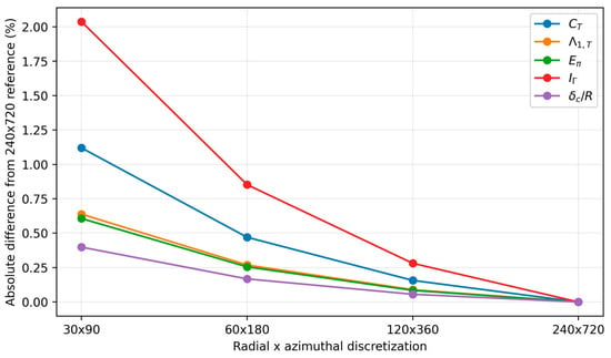
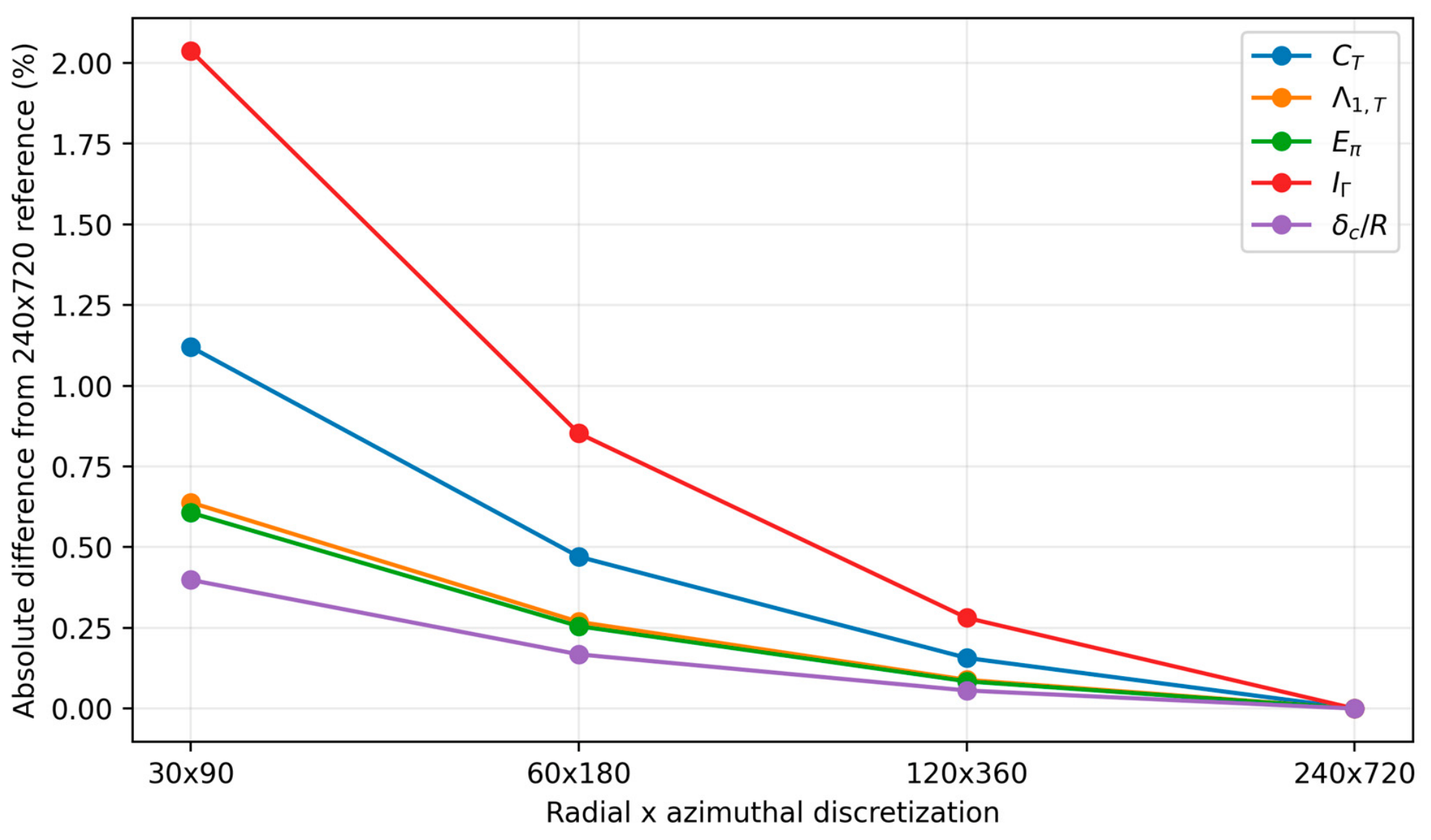
The selected 120 × 360 discretization was close to the 240 × 720 numerical reference in the strongest case. Differences were 0.16% in CT; 0.24% in CQ; 0.09% in Λ1,T; 0.08% in Eπ; 0.28% in IΓ; and 0.06% in . The coarsest 30 × 90 grid produced the largest discrepancy, reaching approximately 2.0% for IΓ. These results support 120 × 360 as a practical numerical resolution for the reduced order matrix. Table 4 reports the convergence values, and Figure 2 shows their absolute percentage differences from the numerical reference.
Table 4.
Discretization convergence for baseline, J = 0.30, α = 30°.
Figure 2.
Absolute discretization difference from the 240 × 720 numerical reference for the strongest modeled case.
4.2. External Benchmark Results
The external comparison is intentionally separated from the axial CFD calibration. The available published datasets do not reproduce the exact present blade geometry, so the benchmark is used to test scale and trend consistency rather than one-to-one validation. UIUC low-Reynolds-number measurements establish the expected coefficient range for small 10-in-class propellers, while Theys et al. [4], Serrano et al. [5], Cerny and Breitsamter [6,7], and Grava et al. [8] provide independent evidence for non-axial trends.
4.2.1. Axial and Low-Reynolds-Number Consistency
The axial comparison is deliberately limited to scale consistency because the UIUC database does not contain the exact reconstructed blade used here. The present CT values of 0.0833 at J = 0.15 and 0.0541 at J = 0.30 fall within the coefficient order expected for small fixed-pitch propellers, but the difference in geometry, section, and Reynolds number distribution precludes a defensible point-by-point error percentage. The axial CFD coefficients used for calibration are therefore not relabeled as experimental validation.
4.2.2. Oblique-Inflow Benchmark
For the present baseline, mean CT rises by 5.3% at J = 0.15 and by 19.6% at J = 0.30 between α = 0° and 30°. Serrano et al. [5] independently reported increasing thrust with disk angle of attack across the investigated advance ratio range and increasing pitch/yaw moments caused by advancing–retreating blade differences. Theys et al. [4] likewise found that BEMT and vortex lattice approaches reproduce the principal oblique flow trends but lose quantitative accuracy as non-axiality increases. Cerny and Breitsamter [6,7] and Grava et al. [8] further document non-axial load and wake changes. These comparisons support the direction and scale interpretation of the present trends, while not constituting direct validation of the newly defined symmetry metrics.
Benchmark summary. UIUC/Brandt and Selig [1] is used only for low-Reynolds-number scale consistency because no exact geometry match is available. Theys et al. [4] provide wind tunnel evidence that BEMT/VLM reproduces the main force and moment trends in oblique flow, while quantitative accuracy decreases as non-axiality grows. Serrano et al. [5] measured four 12-in-class propellers over α = 0–90° and J = 0–0.55 and reported increasing thrust and pitch/yaw moments with incidence; the present model shows +5.3% and +19.6% mean thrust changes from 0° to 30° at J = 0.15 and 0.30, respectively. Cerny and Breitsamter [6,7] and Grava et al. [8] independently document non-axial load and wake reorganization. These comparisons support trend plausibility but not direct validation of Λ1,T, Eπ, or the kinematic wake skew estimate.
4.3. Azimuthal Loading and First-Harmonic Growth
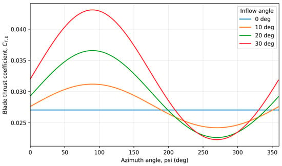
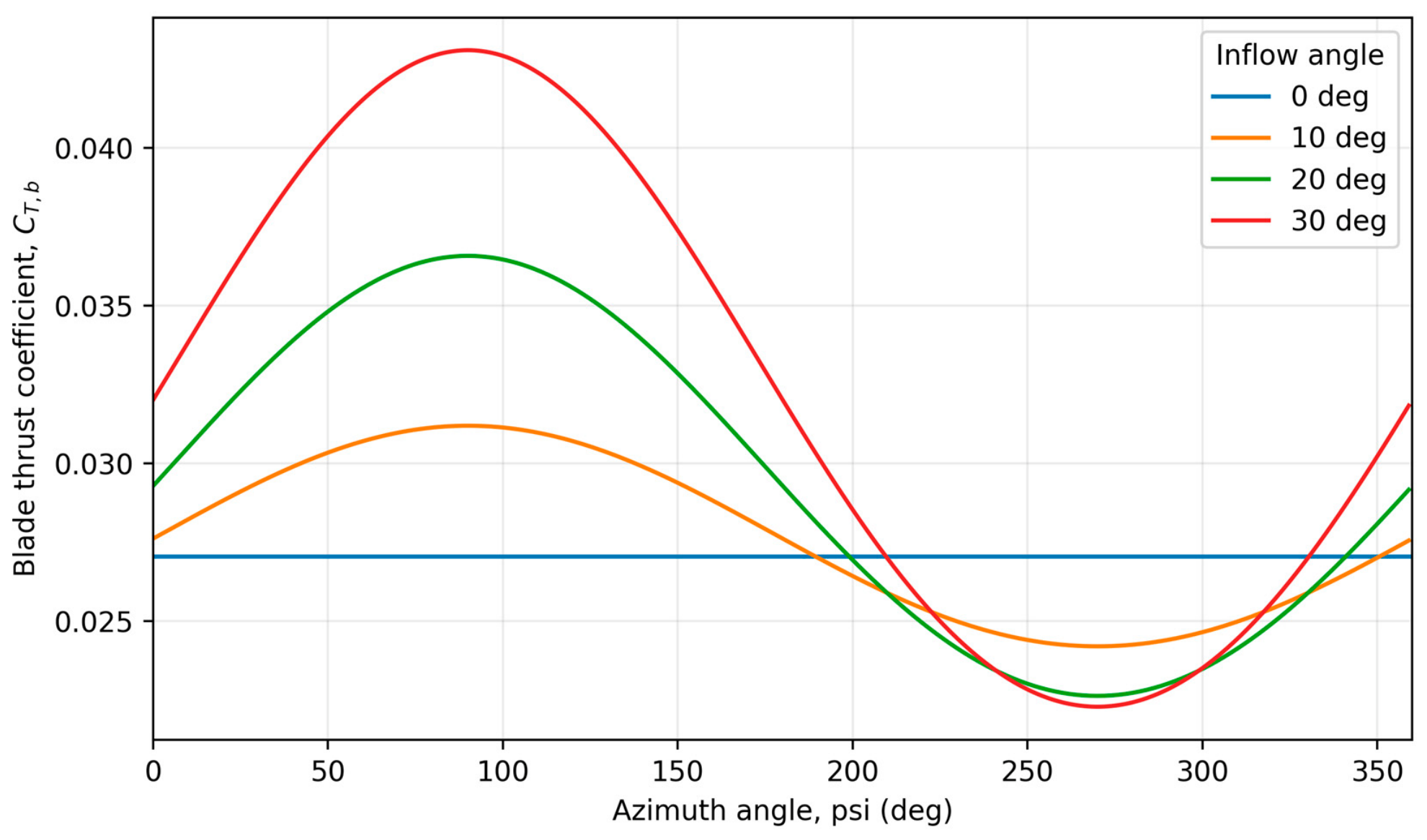
At α = 0°, the blade element model is azimuthally uniform, and both Λ1,T and Eπ collapse to numerical zero. Oblique inflow introduces an approximately sinusoidal once-per-revolution component because the in-plane free stream velocity adds to blade rotational speed on one half-cycle and subtracts on the other. Figure 3 illustrates this progression for the baseline at J = 0.30.
Figure 3.
Phase-locked blade thrust coefficient for the baseline at J = 0.30. The first-harmonic amplitude grows with inflow angle.
For the baseline at J = 0.15, Λ1,T increased from 0.046 at 10° to 0.090 at 20° and 0.129 at 30°. At α = 30°, increasing J from 0.15 to 0.30 increased the normalized first-harmonic ratio from 0.129 to 0.322. However, this relative increase is partly amplified by the concurrent decrease in mean thrust coefficient. The corresponding absolute nondimensional first-harmonic amplitude, CT,1 = CTΛ1,T, increased from approximately 0.0113 to 0.0208, corresponding to an increase of about 84%. Reporting both quantities therefore separates growth of cyclic loading from normalization effects.
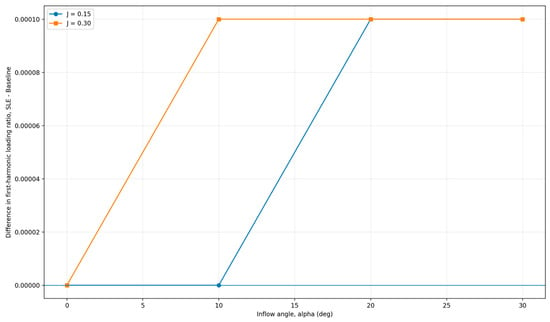
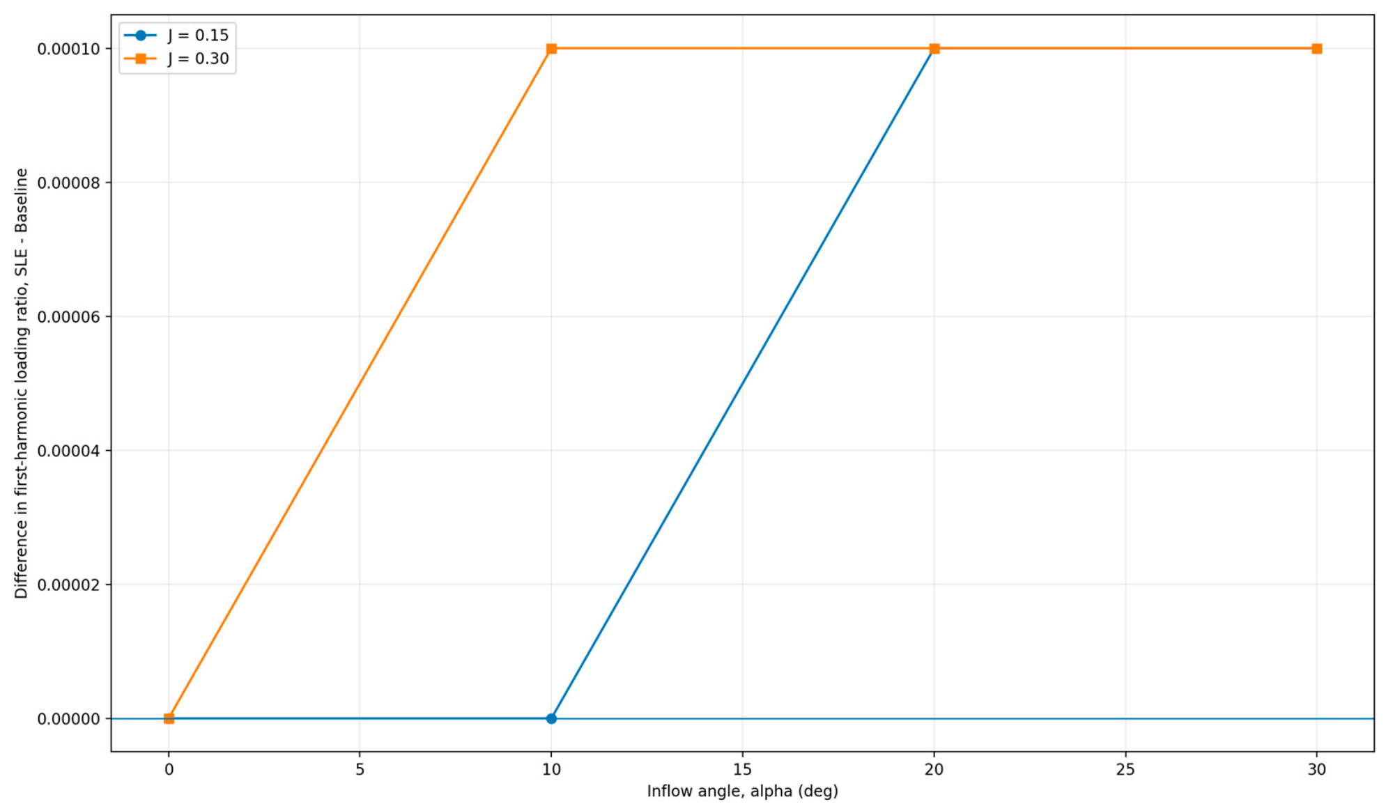
The first-order scaling developed under Small In-Plane Velocity Limit in Section 3.2 is also recovered numerically: at J = 0.15, Λ1,T/sin α is approximately 0.267, 0.263, and 0.258 for α = 10°, 20°, and 30°, respectively. The weak variation of this ratio confirms that the low-incidence response is governed primarily by the imposed in-plane velocity before higher-order induction and sectional-aerodynamic effects become important. The local first-order source term is proportional to (∂dT/∂Ut)V‖ and therefore grows with local rotational speed and chord weighting, placing the dominant sensitivity in the mid-to-outer active span rather than at the root. Figure 4 compares the first-harmonic loading ratios of the two geometries.
Figure 4.
Difference between SLE and baseline first-harmonic thrust loading ratio (SLE − baseline) versus inflow angle. The difference remains small because the simplified sweep correction scales mean and cyclic loading similarly. Blue circles denote J = 0.15, and orange squares denote J = 0.30. The thin horizontal line marks zero difference. Markers identify the computed operating points; connecting lines serve as visual guides.
4.4. Half-Turn Symmetry Loss and Hub Moments
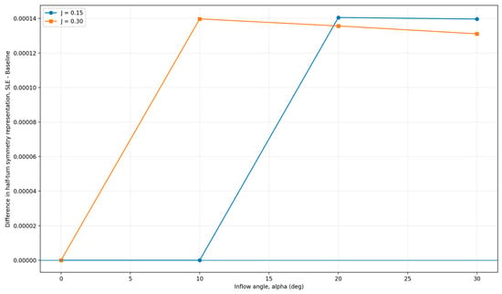
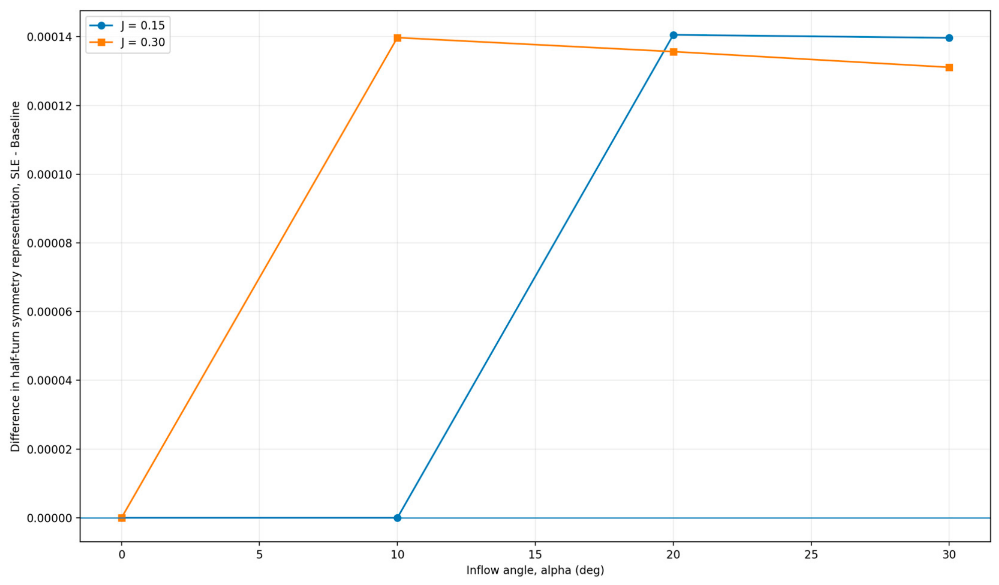
The half-turn quantity is retained as a symmetry space representation, not as an independent aerodynamic observable. For the baseline, it reaches 0.182 at J = 0.15 and α = 30° and 0.444 at J = 0.30 and α = 30°. These values are consistent with the analytical relation to Λ1,T for an almost sinusoidal waveform. The corresponding resultant cross-plane moment coefficients are 0.00254 and 0.00468. Thus, the independent information in this comparison is the growth of the cyclic loading and hub moment response; Eπ provides a direct measure of departure from π-periodicity for the symmetry framework. Figure 5 shows the SLE–baseline difference in the half-turn symmetry diagnostic.
Figure 5.
Difference between SLE and baseline half-turn symmetry representation Eπ (SLE − baseline) versus inflow angle. Eπ is shown as a derived symmetry diagnostic rather than an independent aerodynamic metric. Blue circles denote J = 0.15, and orange squares denote J = 0.30. The thin horizontal line marks zero difference. Markers identify the computed operating points; connecting lines serve as visual guides.
4.5. Mean Thrust Response
The model also reproduced the commonly reported tendency for mean thrust to rise with incidence at fixed J. For the baseline, CT increased from 0.0833 at α = 0° to 0.0878 at 30° for J = 0.15 (+5.3%) and from 0.0541 to 0.0647 for J = 0.30 (+19.6%). This qualitative behavior agrees with the experimental trend reported by Serrano et al. [5] and with incidence-based momentum interpretations [9]. Agreement in trend does not constitute quantitative validation of the present geometry.
Two kinematic effects contribute to this mean thrust change and should not be conflated. Increasing α reduces the axial component Va = V∞ cos α, thereby moving the propeller toward a lower axial advance condition even if the in-plane component were suppressed; simultaneously, V‖ = V∞ sin α generates the advancing–retreating asymmetry. The present reduced order matrix reports the combined response. Consequently, the +5.3% and +19.6% changes are not attributed solely to the in-plane asymmetry when compared with [5]; the comparison is restricted to the total incidence trend.
4.6. Circulation Imbalance and Near-Wake Skew
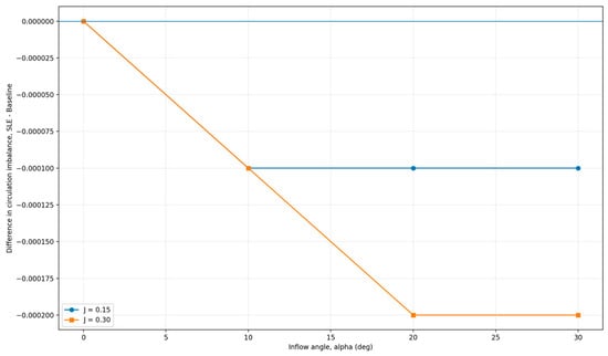
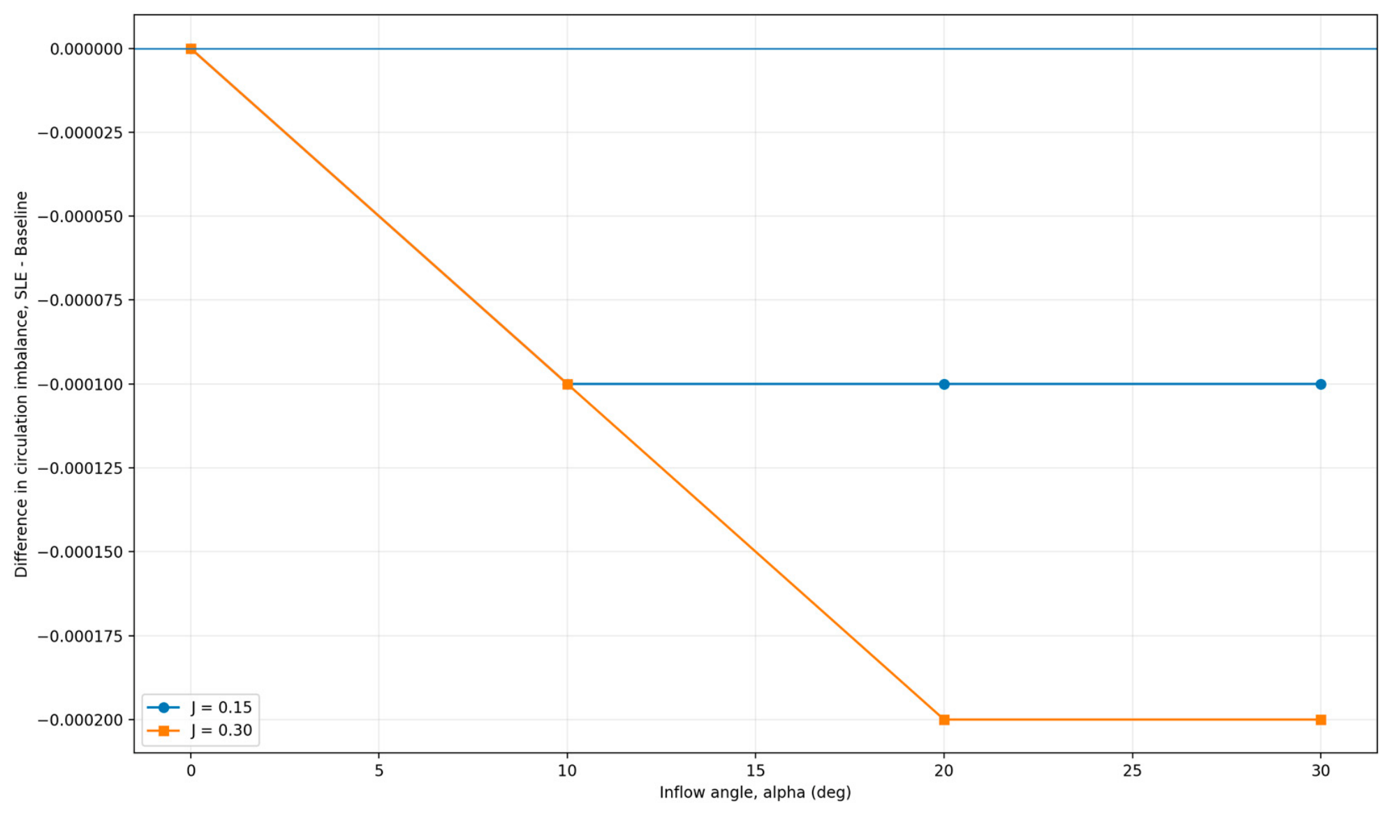
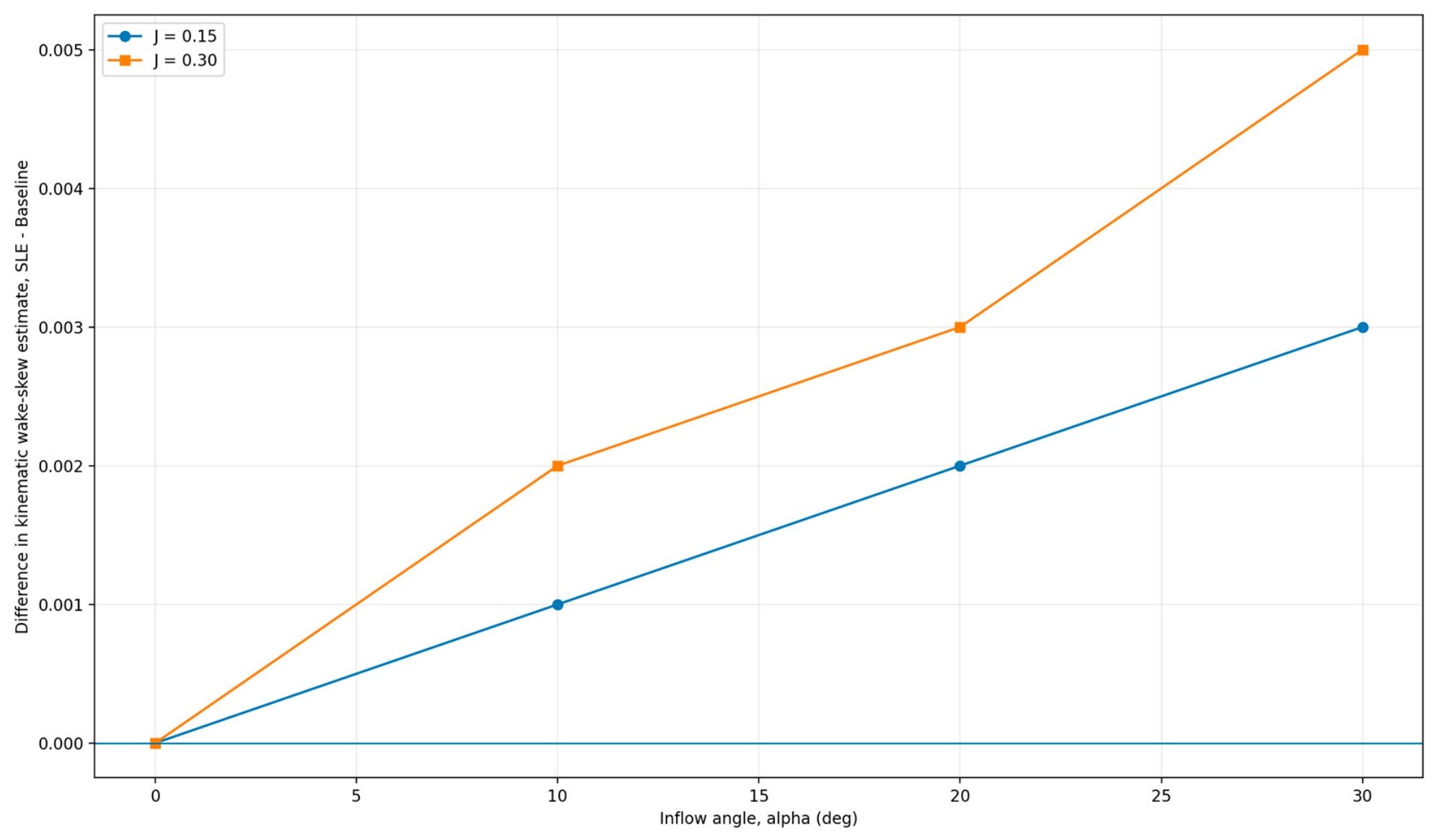
The advancing–retreating circulation imbalance increased with both α and J. For the baseline at α = 30°, IΓ was 0.0655 at J = 0.15 and 0.1787 at J = 0.30, representing a 173% increase. The near-wake skew metric behaved similarly: at x/D = 2, increased from 0.620 to 1.280 when J was increased from 0.15 to 0.30 at α = 30°. These values describe the kinematic wake skew displacement estimate from the actuator disk surrogate; they should not be read as a resolved wake centroid or tip vortex trajectory prediction. Figure 6 and Figure 7 show the corresponding SLE–baseline differences.
Figure 6.
Difference between SLE and baseline advancing–retreating circulation imbalance (SLE − baseline) versus inflow angle. Blue circles denote J = 0.15, and orange squares denote J = 0.30. The thin horizontal line marks zero difference. Markers identify the computed operating points; connecting lines serve as visual guides.
Figure 7.
Difference between SLE and baseline kinematic wake skew displacement estimate at x/D = 2 (SLE − baseline). The quantity is not a resolved wake centroid prediction. Blue circles denote J = 0.15, and orange squares denote J = 0.30. The thin horizontal line marks zero difference. Markers identify the computed operating points; connecting lines serve as visual guides.
4.7. Structural Sensitivity to the Simplified Sweep Representation
The present sweep treatment should not be interpreted as a physical assessment of three-dimensional swept blade aerodynamics. The cos2Λ correction acts primarily as a local force-scale modification and does not introduce an additional azimuth-dependent mechanism. Consequently, normalized cyclic metrics are expected to remain nearly unchanged by construction. The SLE case is therefore retained only to demonstrate this structural property of the reduced order formulation and is not used to conclude that physical leading edge sweep has negligible influence under oblique inflow. Quantitative assessment of swept blade three-dimensional effects requires CFD or experimental resolution beyond the present model. Table 5 summarizes the results for all sixteen operating cases.
Table 5.
Primary reduced order results for the sixteen operating cases.
4.8. Local Model-Form Sensitivity
After recalibrating each perturbed model to the same axial CT and CQ targets, the strongest non-axial case was relatively insensitive to ±10% lift slope and ±20% CD0 changes. The zero-lift angle had the largest influence: shifting α0 by −1° reduced Λ1,T to approximately 0.291, whereas shifting it by +1° increased Λ1,T to approximately 0.367. Eπ ranged from 0.403 to 0.502 over the same perturbation. This sensitivity confirms that the absolute magnitudes depend on the assumed low-Reynolds-number sectional polar even though the qualitative dependence on α and J is robust within the tested perturbations. Table 6 summarizes the recalibrated sensitivity cases.
Table 6.
Local model-form sensitivity for baseline, J = 0.30, and α = 30°. Each perturbation is recalibrated at the axial reference.
5. Discussion
The reduced order results separate two effects that are often conflated. Geometric symmetry is a property of the solid rotor, whereas aerodynamic symmetry is also controlled by the external velocity field. A two-bladed rotor can remain exactly invariant under a 180° geometric rotation while developing large once-per-revolution blade loads because the in-plane component of oblique inflow does not rotate with the blade. The strong growth of Λ1,T and Eπ with α and J is therefore not a numerical defect; it is the expected mathematical consequence of a preferred external direction.
Within the present first-order sweep representation, the operating condition effect was substantially larger than the modeled effect of the modest swept planform. The sweep correction primarily modifies the local force scale in the outer blade region and therefore produces similar proportional changes in mean and cyclic loading. Consequently, the near-invariance of the normalized symmetry metrics should be interpreted as a result of the present reduced order representation rather than as evidence that sweep is universally ineffective in mitigating oblique inflow asymmetry. Higher fidelity models may capture three-dimensional swept blade effects that are outside the scope of the present formulation.
The model trends are consistent with published non-axial studies in two respects. First, mean thrust increases with incidence at fixed advance ratio [5,9]. Second, pitch/yaw moments and blade-to-blade load differences grow as the advancing–retreating asymmetry becomes stronger [4,5,6,7,8]. The present results should nevertheless be interpreted as trend-level evidence. Theys et al. [4] explicitly showed that low-order methods lose quantitative accuracy in oblique flow, which is why the current paper does not claim high-fidelity wake prediction or experimental validation.
The local model-form sensitivity provides a practical uncertainty scale for the present operating matrix. At J = 0.30 and α = 30°, varying the zero-lift angle by ±1° changes Λ1,T from 0.291 to 0.367 around the nominal 0.322 (approximately −10% to +14%) and changes IΓ from 0.159 to 0.208 (approximately −11% to +16%). The kinematic wake skew estimate varies much less (about ±3%). In addition, the quasi-steady assumption may overstate cyclic amplitude by roughly 15% at reduced frequency k ≈ 0.12, and uniform induction does not reproduce the phase shifts associated with longitudinal/lateral inflow variation [12,13,14]. These ranges define the practical validity boundary of the model more usefully than a single nominal value: the formulation is appropriate for trend screening over J = 0.15–0.30 and α ≤ 30°, but not for phase-accurate loads, high-incidence flow, resolved wake topology, or certification-level prediction.
The half-turn quantity Eπ is retained because it expresses loss of the nominal π-periodic blade state in a form directly relevant to symmetry analysis. For the nearly sinusoidal histories generated by the present model it is analytically dependent on Λ1,T, so it is not counted as independent aerodynamic evidence. Its value is diagnostic: departures from the analytical Λ1,T–Eπ relation would reveal higher harmonic or non-sinusoidal loading. Likewise, IΓ is derived from the modeled sectional circulation and is not presented as a substitute for a resolved wake visualization.
The strongest modeled condition, J = 0.30 and α = 30°, is a natural candidate for a later high-fidelity verification campaign. A targeted URANS or experimental campaign could measure phase-resolved thrust/moment histories and near-wake velocity at this single operating point before expanding the matrix. Such a staged strategy is more defensible than treating a reduced order model as a substitute for CFD or laboratory measurements.
6. Limitations
This study is a physics-based reduced order analysis, not an experiment or CFD simulation. The blade geometry is represented by a reconstructed chord law and constant-pitch helical angle rather than the complete CAD surface. Sectional aerodynamics use a quasi-steady clipped linear lift law and quadratic drag polar. The representative Reynolds number range is low, the zero-lift angle is influential, and no measured polar for the exact blade section is available. A Prandtl tip loss factor is not included explicitly. The induced velocity is uniform over the disk, so standard longitudinal/lateral inflow variation and dynamic inflow are not resolved. The kinematic wake skew displacement uses a far wake momentum velocity in an algebraic extrapolation and is not a resolved vortex trajectory or wake centroid prediction. The first-order sweep correction represents only the macroscopic normal flow effect of outer-span sweep. Transition, Reynolds number-dependent section polars, blade flexibility, motor/airframe interference, rotor–rotor interaction, atmospheric turbulence, and acoustic radiation are outside the present scope. The results therefore support relative trends, bounded symmetry diagnostics, and hypothesis generation, not certification-level performance prediction.
7. Conclusions
- Oblique inflow generates a once-per-revolution blade-loading component even when the two-bladed rotor remains geometrically symmetric. The first-order model and the numerical matrix both show Λ1,T scaling approximately with J sin α at moderate incidence.
- Normalized and absolute cyclic loading must be distinguished. At α = 30°, increasing J from 0.15 to 0.30 raises Λ1,T from 0.129 to 0.322, while the absolute nondimensional first-harmonic amplitude rises from approximately 0.0113 to 0.0208 (about 84%). The previously quoted 149% normalized increase therefore includes the concurrent decrease in mean thrust.
- Eπ is not an independent aerodynamic metric for the nearly sinusoidal load histories produced here; it is a symmetry space representation analytically linked to Λ1,T. It is retained as a diagnostic of π-periodicity and potential higher harmonic departure.
- The 10° outer-span sweep case cannot be used to conclude that physical sweep is ineffective. Under the present cos2Λ-type force correction, mean and cyclic loading are scaled similarly, so normalized differences below 0.5% are largely a structural consequence of the reduced order representation. Three-dimensional sweep effects require CFD or experiment.
- External literature comparisons support the direction of the predicted non-axial trends—rising thrust and cross-plane loading with incidence and altered wake organization—but do not provide geometry-matched validation of Λ1,T, Eπ, or the wake skew estimate. Local model-form sensitivity indicates approximately −10% to +14% uncertainty in Λ1,T from a ±1° zero-lift angle perturbation at the strongest case, with an additional order of 15% quasi-steady amplitude uncertainty at k ≈ 0.12.
- The practical validity range of the present formulation is moderate oblique inflow (J = 0.15–0.30, α ≤ 30°) for rapid trend screening and symmetry diagnostics. The strongest condition, J = 0.30 and α = 30°, remains the recommended point for future phase-resolved CFD/PIV or load cell validation.
Supplementary Materials
The following supporting information can be downloaded at: https://www.mdpi.com/article/10.3390/sym18111824/s1, Supplementary File S1. Computational reproducibility package for the reduced-order propeller model under oblique inflow. The archive contains the Python model and analysis scripts, software requirements, execution instructions, numerical datasets in CSV format, a JSON summary of numerical consistency checks, and Figures S1–S9 in 600-dpi PNG and vector PDF formats.
Author Contributions
Conceptualization, D.S.-H., G.U.-S., G.R.-R., and J.P.-O.; methodology, D.S.-H., G.U.-S., J.P.-O., I.A.-M., and F.A.D.-P.; formal analysis, D.S.-H., B.R.-A., J.M.-R., I.A.-M., C.H.-A., and F.R.E.-P.; investigation, D.S.-H., C.E.H.-B., F.C.-G., A.P.C.-S., J.M.-H., C.H.-A., and J.A.G.-N.; resources, G.U.-S., F.A.D.-P., and G.R.-R.; data curation, D.S.-H., F.C.-G., A.P.C.-S., J.R.G.-I., L.I.L.-C., C.H.-A., and J.M.-H.; writing—original draft preparation, D.S.-H.; writing—review and editing, D.S.-H., G.U.-S., G.R.-R., B.R.-A., J.M.-R., J.P.-O., M.P.-O., I.A.-M., J.M.-H., C.E.H.-B., F.C.-G., A.P.C.-S., J.R.G.-I., L.I.L.-C., F.R.E.-P., F.A.D.-P., C.H.-A., and J.A.G.-N.; visualization, D.S.-H., J.R.G.-I., and F.R.E.-P.; supervision, G.U.-S., G.R.-R., and J.P.-O.; project administration, D.S.-H., G.U.-S., and J.P.-O. All authors have read and agreed to the published version of the manuscript.
Funding
This research received no external funding.
Data Availability Statement
The complete reduced numerical dataset and the Python implementation (https://www.python.org/, accessed on 28 October 2026) used to generate the reported tables and figures are provided as Supplementary Materials. The model contains no experimental or proprietary CFD field data.
Acknowledgments
The authors acknowledge the institutional support provided for the development of the computational workflow. During the preparation of this manuscript, the authors used Grammarly (https://www.grammarly.com/, accessed on 28 October 2026) and QuillBot (https://quillbot.com/, accessed on 28 October 2026) for English grammar correction, language polishing, and improvement of textual clarity and coherence. The authors reviewed and edited the output and take full responsibility for the content of this publication.
Conflicts of Interest
The authors declare no conflicts of interest.
Appendix A. Reproducibility Notes
The supplementary Python script reconstructs the reduced order geometry, performs the axial calibration, solves the sixteen operating cases, computes all symmetry metrics, and regenerates the CSV tables and figures. The numerical values in the manuscript should therefore be treated as outputs of that explicit model. Rerunning the script with different polar assumptions is encouraged because the local sensitivity analysis shows that sectional aerodynamic assumptions influence the absolute asymmetry magnitude.
References
- Brandt, J.B.; Selig, M.S. Propeller Performance Data at Low Reynolds Numbers. In Proceedings of the 49th AIAA Aerospace Sciences Meeting, Orlando, FL, USA, 4–7 January 2011. [Google Scholar] [CrossRef] [Scilit]
- Gur, O.; Rosen, A. Propeller Performance at Low Advance Ratio. J. Aircr. 2005, 42, 435–441. [Google Scholar] [CrossRef] [Scilit]
- McCrink, M.H.; Gregory, J.W. Blade Element Momentum Modeling of Low-Reynolds Electric Propulsion Systems. J. Aircr. 2017, 54, 163–176. [Google Scholar] [CrossRef] [Scilit]
- Theys, B.; Dimitriadis, G.; Hendrick, P.; De Schutter, J. Experimental and Numerical Study of Micro-Aerial-Vehicle Propeller Performance in Oblique Flow. J. Aircr. 2017, 54, 1076–1084. [Google Scholar] [CrossRef] [Scilit]
- Serrano, D.; Ren, M.; Qureshi, A.J.; Ghaemi, S. Effect of Disk Angle-of-Attack on Aerodynamic Performance of Small Propellers. Aerosp. Sci. Technol. 2019, 92, 901–914. [Google Scholar] [CrossRef] [Scilit]
- Cerny, M.; Breitsamter, C. A Comparison of Isolated and Ducted Fixed-Pitch Propellers under Non-Axial Inflow Conditions. Aerospace 2020, 7, 112. [Google Scholar] [CrossRef] [Scilit]
- Cerny, M.; Breitsamter, C. Investigation of Small-Scale Propellers under Non-Axial Inflow Conditions. Aerosp. Sci. Technol. 2020, 106, 106048. [Google Scholar] [CrossRef] [Scilit]
- Grava, A.; Serpieri, J.; Iuso, G.; Bernardos, L.; Cafiero, G. Experimental Investigation of a Small Drone Propeller Aerodynamics in Forward Flight. AIAA J. 2025, 63, 1855–1866. [Google Scholar] [CrossRef] [Scilit]
- Rubin, R.L.; Zhao, D. New Development of Classical Actuator Disk Model for Propellers at Incidence. AIAA J. 2021, 59, 1040–1054, Correction in AIAA J. 2022, 60, AU1. https://doi.org/10.2514/1.J059734.c1. [Google Scholar] [CrossRef] [Scilit]
- Ribner, H.S. Propellers in Yaw; National Advisory Committee for Aeronautics: Washington, DC, USA, 1945.
- de Young, J. Propeller at High Incidence. J. Aircr. 1965, 2, 241–250. [Google Scholar] [CrossRef] [Scilit] [PubMed]
- Leishman, J.G. Principles of Helicopter Aerodynamics, 2nd ed.; Cambridge University Press: Cambridge, UK, 2006. [Google Scholar]
- Johnson, W. Helicopter Theory; Princeton University Press: Princeton, NJ, USA, 1980. [Google Scholar]
- Glauert, H. The Elements of Aerofoil and Airscrew Theory, 2nd ed.; Cambridge University Press: Cambridge, UK, 1947. [Google Scholar]

Disclaimer/Publisher’s Note: The statements, opinions and data contained in all publications are solely those of the individual author(s) and contributor(s) and not of MDPI and/or the editor(s). MDPI and/or the editor(s) disclaim responsibility for any injury to people or property resulting from any ideas, methods, instructions or products referred to in the content. |
© 2026 by the authors. Licensee MDPI, Basel, Switzerland. This article is an open access article distributed under the terms and conditions of the Creative Commons Attribution (CC BY) license.