


Abstract
Piping systems must cope with the internal pressure of the fluid they carry. They are almost always well-designed for withstanding steady-flow pressures, but allowing for unsteady-flow pressures and for fatigue can be more challenging. Positive and negative gauge pressures induced by waterhammer waves are possibly the most extreme that piping is likely to face during its lifetime. It is widely accepted that this should be addressed by analyses during the design phase, but this is usually done under the assumption that consequential (non-hoop) structural movements do not affect the calculated pressures. However, the calculated pressures are used as input to the structural design. Commonly, attention focusses on static predictions of induced hoop stresses and on the risk of buckling, but attention sometimes has to be paid to dynamic responses. In these cases, the complexity of the structural analysis depends on the assumed degrees of freedom of possible movement, so it is desirable to avoid including unnecessary detail. The title of this paper poses one question that is frequently asked. However, the correct answer is not always obtained, partly because highly misleading answers were published in one early paper, the rebuttals to which were much less widely reported. The current contribution attempts to answer the question for both fixed and movable bends. Attention is paid to pressure transients arriving at bends from remote locations and potentially inducing pipe movement. Then, the opposite effect is considered, namely the generation of pressure transients by structural movements. To avoid distorting the picture by combining this with nominally unrelated causes, strong simplifications are made—e.g., disregarding all forms of energy dissipation.
1. Introduction
Do waterhammer waves pass pipe bends without noticing them? That is, are they (the waves) unaffected by them (the bends)? This question has been asked (to the authors and in general) and discussed many times, but being justifiably confident about answering it correctly can be difficult. The issue is reconsidered, including references to two not-to-be-forgotten papers from the 1960s, [1] Contractor (1965) and [2] Swaffield (1968–1969), that were instructive in many ways, noting that the latter has misled researchers ever since. Later insights with respect to fluid–structure interaction at elbows as reviewed by [3] Tijsseling (2019) should be considered. The primary purpose of this paper is to discuss and, at least partially, answer the question posed in the title.
The discussion begins in Section 2 with consideration of pressure waves in a pipe with a bend that is restrained to prevent any structural movement. This is followed in Section 3 by an assessment of pressure waves in pipes with bends that are able to move in at least one axial direction. Section 4 focusses on structural motion induced by prescribed pressure changes and it allows for the influence of those movements on subsequent pressures. This interactive behaviour is an example of two-way fluid–structure interaction (FSI). Section 5 considers FSI caused by externally imposed structural movement. In this instance, the presented analysis considers resulting pressure waves in the fluid. However, no allowance is made for the corresponding influence of the pressure waves on the structural motion. This is an example of one-way FSI (structure to fluid). In engineering practice, use is also made of one-way FSI (fluid to structure) in which the phenomenon is simulated in two steps, namely (i) a pressure surge analysis assuming stationary pipes (except for pressure-induced hoop-deformation) followed by (ii) a structural analysis of the response to the simulated pressures. All cases considered are examples of so-called ‘junction-coupling’ at the elbow, a general FSI term that also embraces coupling at joints, branches, valves, etc.
Simplifications
The whole paper is targeted at clarifying the influence of pipe bends on waterhammer waves. This is achieved by disentangling the targeted phenomena from as many potential complications as possible. For example, another form of FSI known as Poisson-coupling also exists but is disregarded herein. In pipework typically used in engineering applications, it is usually a weaker effect than junction coupling [4] Wiggert (1986). All possible causes of fluid or structural damping are also excluded, even though many such causes need to be considered when undertaking simulations for practical purposes or when attempting to deduce causes of unexpected behaviour, whether physical, numerical or analytical [5] Leslie & Tijsseling (1999); [6] Vardy (2023). Other simplifications include (i) assuming that the waves in the fluid and in the pipe wall travel at constant speeds, regardless of variations in pressures, stresses and velocities, and (ii) limiting attention to 90° bends.
In addition to simplifying, ensuring a clear focus on the physical phenomena under investigation, these simplifications enable the interactions to be expressed clearly in the equations presented below. They also make possible the development of symbolic solutions that express the behaviour in analytical forms that can be interpreted without the need for numerical methods. Useful generic information can also be inferred by means of dimensional analysis [1] Contractor (1965); [2] Swaffield (1968–1969); [7] Wylie (1996); however, that approach is not followed herein.
2. Fixed Bends: Do They Exist in Practice?
It is useful to begin with a discussion of pressure waves in pipes with fixed bends. In steady flows, account is usually taken of pressure losses at bends and junctions and other interruptions to simple flow in a straight pipe. These result from secondary flows, flow separation, vortex shedding and enhanced turbulence. Examples for simple bends are described by [8] Itō (1960) and [9] Smyk et al. (2024). Such losses are neglected herein, partly for simplicity, but mostly because they are usually far smaller than pressure changes caused by waterhammer-like waves. For simple bends, the losses are typically less than ½ ρV2, where ρ and V are the fluid density and axial velocity. When the passage of a pressure wave changes the velocity, the change in this pressure loss is less than ½ ρ Δ(V2). In contrast, the pressure change caused by the wave is in the order of ρ a ΔV where a is the wave speed. The ratio of these two changes is in the order of the flow Mach number, V/a, which is almost always very small in liquid flows and is commonly also small in gas flows. For completeness, however, it is noted that these so-called ‘minor’ losses can be large in other contexts, notably partially closed valves or orifices such as those used by [1] Contractor (1965) to generate losses of up to 1150 × ½ ρV2. These cases are not considered herein, and neither are other causes such as entrapped gas in an elevated bend [10] Bergant et al. (2008). Similarly, no account is taken of specialized phenomena such as extreme cases of plastic deformation [11] Florence (1975); [12] Youngdahl et al. (1981). Also, Cartwright (1977) [13] showed that locally increased Boussinesq momentum correction coefficients [14] Vardy & Tijsseling (2022) have negligible consequences.
Impossibility of Reflections from Fixed Bends
We begin by demonstrating that, with the above simplifications, reflections from structurally fixed bends in uniform pipes are impossible. The following assessment applies equally well to a case where few, if any, persons would imagine a reflection to be possible, namely a simple join between two pipes of equal bore (disregarding the fact that flanges and welds give tiny reflections because of the increased local stiffness and mass of the pipe’s wall). A simple proof is possible by assuming that a sustained reflection is possible and showing that this leads to a contradiction.
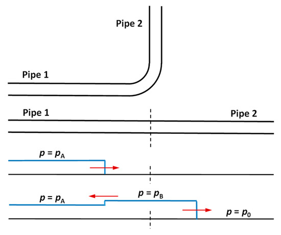
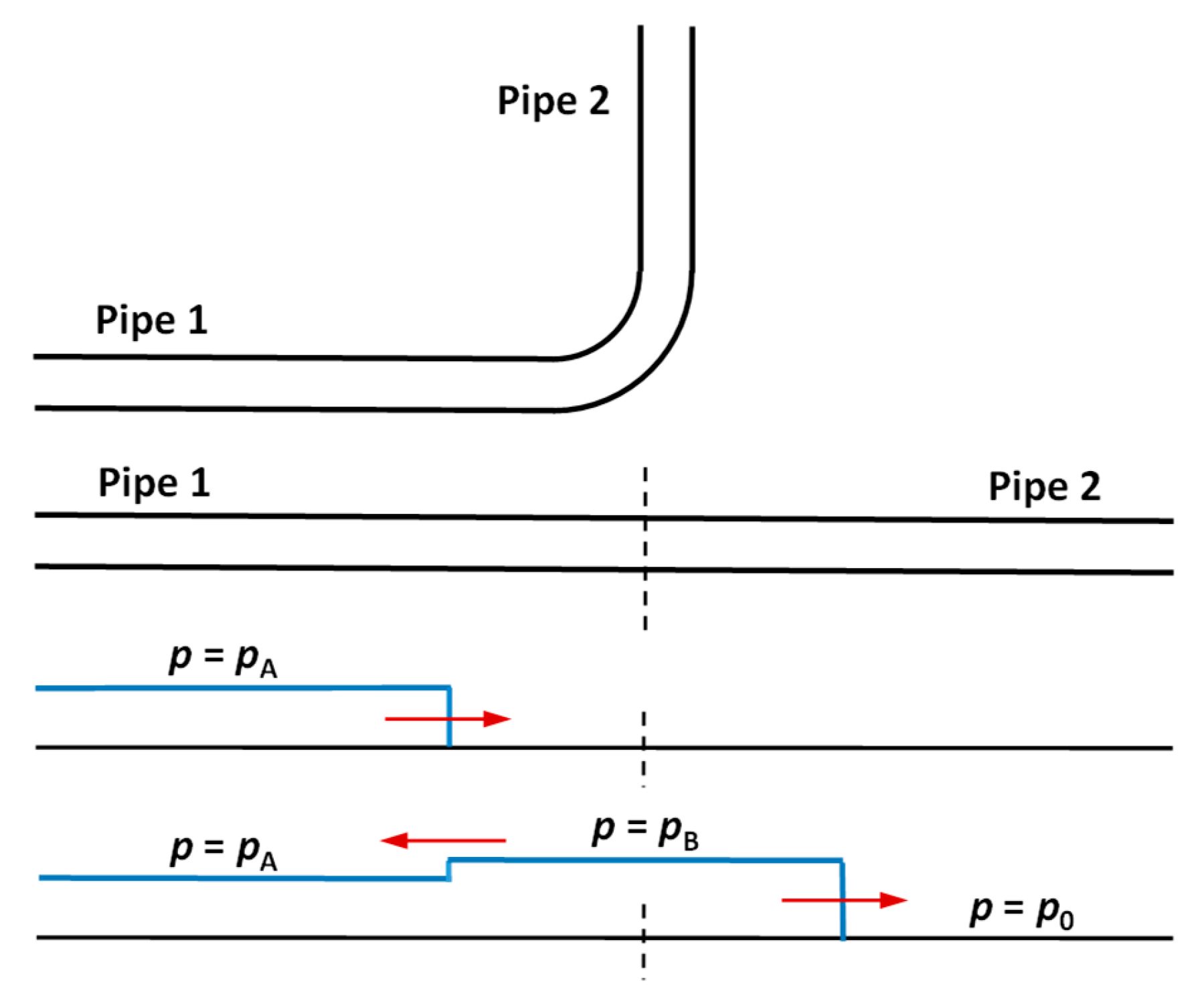
Figure 1 shows a step wavefront approaching such a bend/join. The initial steady flow pressure and velocity in limbs 1 and 2 are P0 and V0 and the approaching pressure wave increases these to PA and VA. The figure also shows (i) an assumed reflection in the upstream limb 1 and (ii) the ongoing wavefront in the downstream limb 2. In this illustration, both the incident wavefront and the wavefront in limb 2 are deemed to cause increases in pressure, so PB > PA. Continuity of pressure requires that the amplitude of the wavefront transmitted into limb 2 is also equal to PB.
Figure 1.
Indicative pressure distributions implied by a sustained reflection of a wavefront at an internal boundary in a uniform pipe.
Now consider the implied velocities:
- In limb 1, the positive reflection of pressure reduces the velocity so VB1 < VA
- In limb 2, the pressure exceeds PA and so VB2 > VA
That is, for the assumed conditions, VB2 is not equal to VB1. Clearly, this is inconsistent with the requirements of conservation of mass, and it follows that the original assumption violates elementary laws of physics. Therefore, the hypothesised reflection in limb 1 is impossible. Strictly, this has been demonstrated only for the case of a compressive wavefront and a compressive reflection. However, the same conclusion is reached if either (or both) of these is deemed to be negative. Accordingly, no further attention is paid in this paper to fixed, loss-free bends in uniform pipes. Instead, the focus is on the influence of bends that do not remain stationary.
One critical note: wave reflection due to pure scattering (because of the 2D or 3D geometry of the bend) occurs but is negligible for long (relative to pipe diameter) wavelengths [15] Martin (2023).
3. Bends That Are Free to Move: Overview
3.1. Swaffield
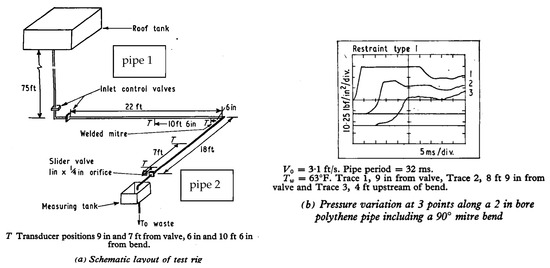
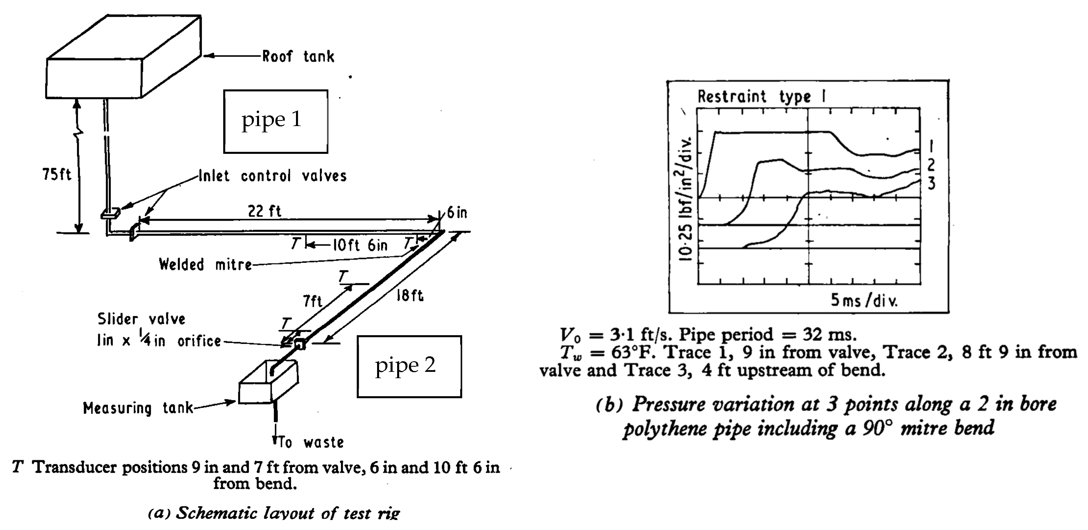
Swaffield (1968–1969) [2] investigated experimentally the influence of bends with a range of axial curvature (maximum radius of curvature of 5D) and angles (30°, 60°, 90° and 135°) on the reflections of pressure waves. He buttressed the bends in a manner that he considered could be regarded as perfectly fixed, and obtained measurements that clearly showed reflections (e.g., Figure 2b). Furthermore, they showed a dependence on the bend curvature and the bend angle. He interpreted the measurements as waterhammer reflections from bends and reported his conclusions accordingly. We now realise, of course, that the bends cannot have been adequately fixed and, indeed, Swaffield himself reached this conclusion after discussion with others. Evidence for this is cited by the following authors:
Figure 2.
Negative reflection of pressure wave from bend as observed by Swaffield [2], (1968–1969).
Cartwright, 1977 [13]:
The work described in the bulk of this (Cartwright’s) thesis assumed that no bend motion took place and that the bend was rigidly held. This assumption was based on the work of Swaffield (1968–1969) who, as already stated, attempted to eliminate bend motion. Swaffield (141) pointed out that in view of the arguments repeated in the first section of this chapter, it is unlikely that this was so.” N.B. Cartwright’s Ref. 141 cited as: Swaffield. Private communication.
Wilkinson, 1980 [16]:
On the effect of restraints, Swaffield found little or none but decided later, Ref. 5, that the restraints he had used had not been sufficient to reduce the very small displacement that occurred. His results are effectively unrestrained.” N.B. Wilkinson’s Ref. 5 cited as Swaffield, J. A. Private communication. (1976).
Unfortunately, these rebuttals were not widely seen and, for many years, Swaffield’s published paper was accepted at face value by a significant number of researchers. Indeed, as recently as two years ago, answers generated by AI searches were seriously misleading (although they have improved noticeably since then). For the avoidance of doubt, therefore, we declare unequivocally that the negative reflection seen in Figure 2b herein were a consequence of bend motion. An assessment of the movement needed to cause the measured reflections is given in Section 4.6.
3.2. Wylie & Streeter
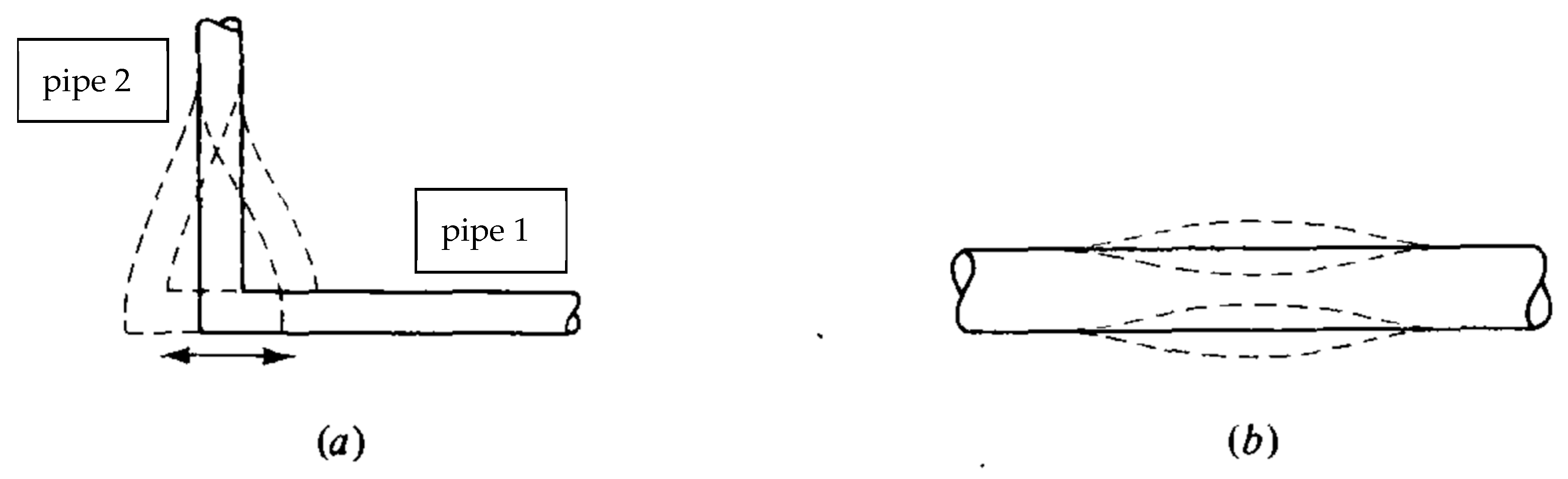
The pumping mechanism of vibrating bends and panting (breathing) of pipes is well known. For example, the classic textbook by Wylie & Streeter (1993) [17] includes the following statements:
“There are two basic types of exciters that may perturb a system. They may act independently, in unison, or in combination with other elements. The two are:
- An element that provides an oscillatory flow across it but maintains a common head. This may be classified as a capacitance element, as it has the capability of storage. It may be a moving pipe bend as shown in Figure 3, left, a “panting” penstock as shown in Figure 3, right, or any other device with an elastic behaviour.Figure 3. Capacitance elements (in [17], Section 13-8): (a) vibrating elbow; (b) breathing pipe.
- An element that provides an oscillatory head across it but maintains a common discharge. This is a resistance element or an inertia element. A turbomachine or variable-loss element may fall into this category. A variable loss may arise due to eddy shedding or hydroelastic interaction between fluid and structural components.”
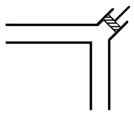
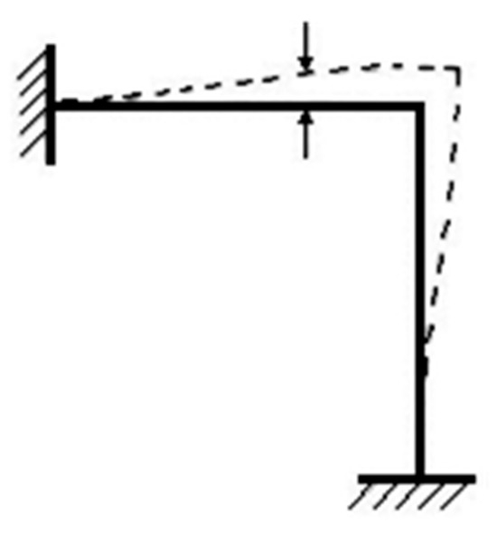
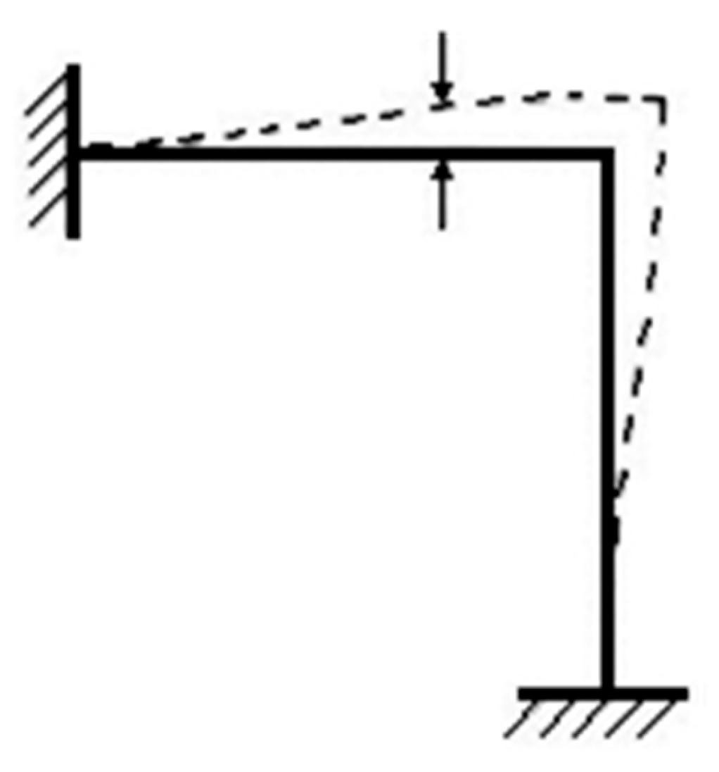
As illustrated in Figure 3a, the axial vibration of pipe 1 causes bending in pipe 2. For a rigid elbow, to keep its angle right, this implies some bending in pipe 1 too.
3.3. Cartwright
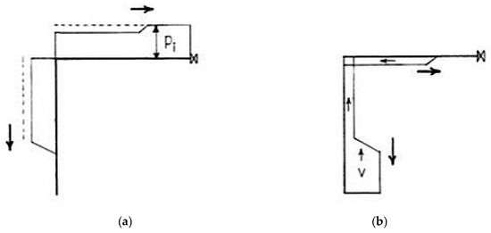
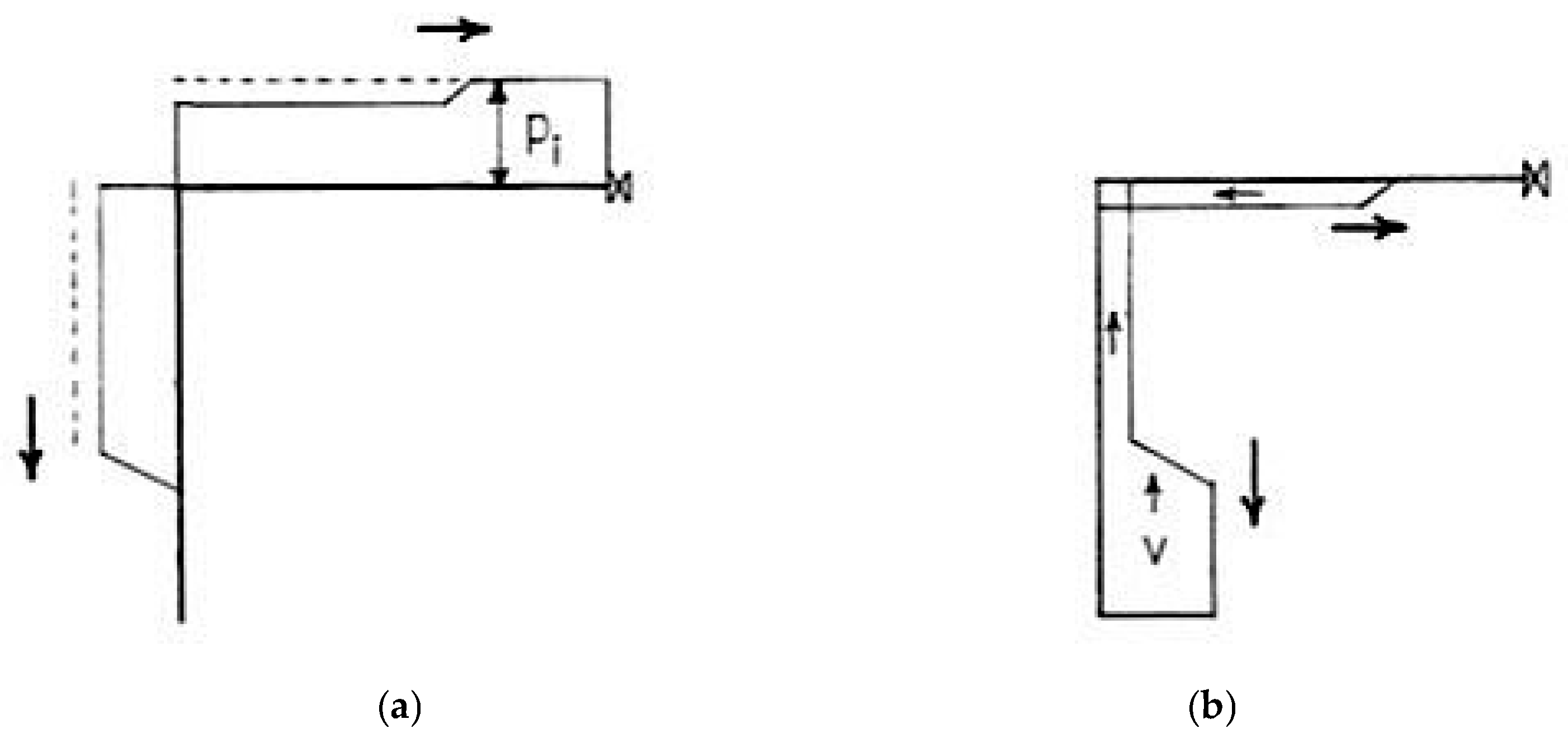
Whereas the first reflection of a positive pressure wave from a minor loss (if detectable) from a fixed bend would be positive [1], it is negative from a bend that is free to move because this creates additional storage (e.g., Figure 3a). Cartwright’s (1977) [13] explanation of this mechanism is illustrated in Figure 4. The reflection (when observed in measured pressure signals) tells something about the “stiffness” of external supports at the bend. Related work on elbows worth reading is by Belytschko et al. (1982, 1986) [18,19] and Tijsseling et al. (1996) [20]. Further reference to Cartwright’s work is made in Section 4.3 and Section 5.2.
Figure 4.
Wave reflection at a moving bend according to Cartwright 1977 ([13], Figure 10.2). (a) Pressures after transmission and reflection of a positive incident pressure wave pi caused by valve closure on the right end (as bottom graphs in Figure 1). (b) Fluid velocities after transmission and reflection; the initial steady fluid velocity before valve closure is V.
4. Analysis: Fluid-Induced Disturbances in the Structure
4.1. Fully Fixed Bends
Extensive literature exists regarding pressure surges in pipework that is deemed to be immovable. Therefore, no useful purpose would be served by presenting further analysis of it herein. Instead, we simply cite the well-known Joukowsky relationship between changes (indicated by Δ) in pressure and velocity induced by isolated wavefronts in pipes, namely, the following:
where H = P/(ρg) is the pressure head, ρ is the fluid density, a is the speed of wave propagation, g is gravitational acceleration, and V is the fluid velocity. This is used below as a reference condition.
4.2. Bends That Are Moving
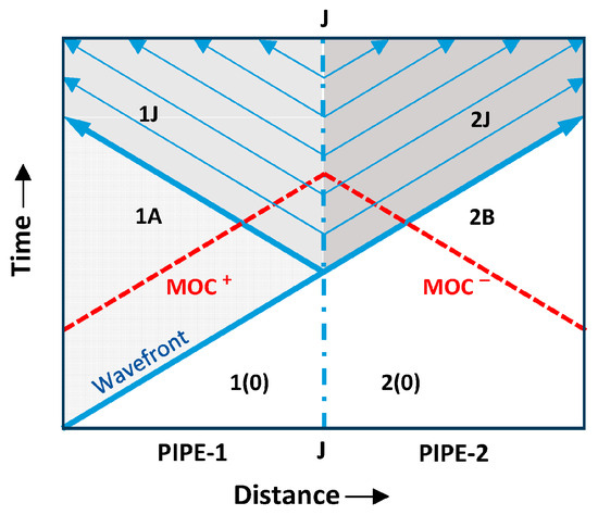
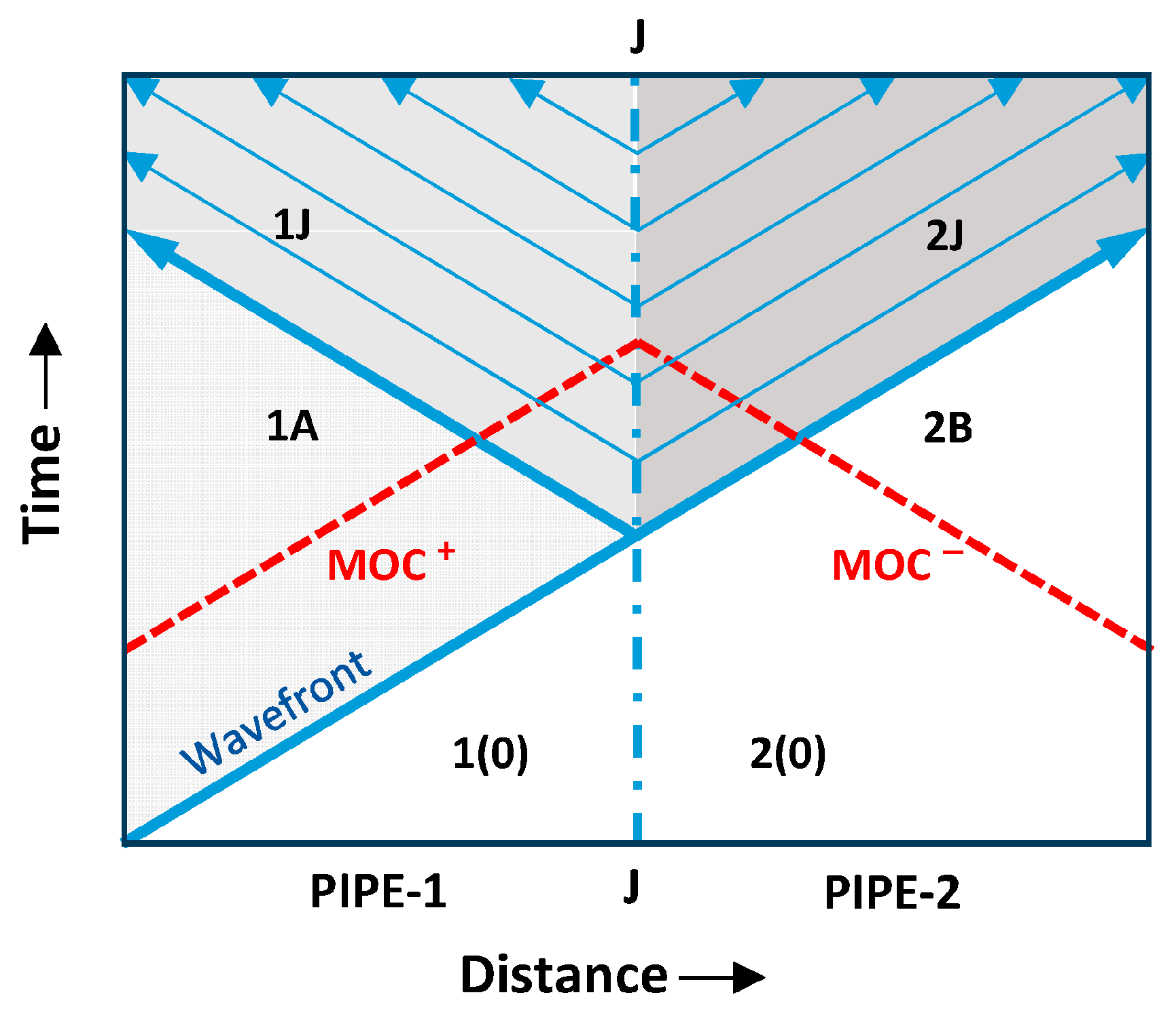
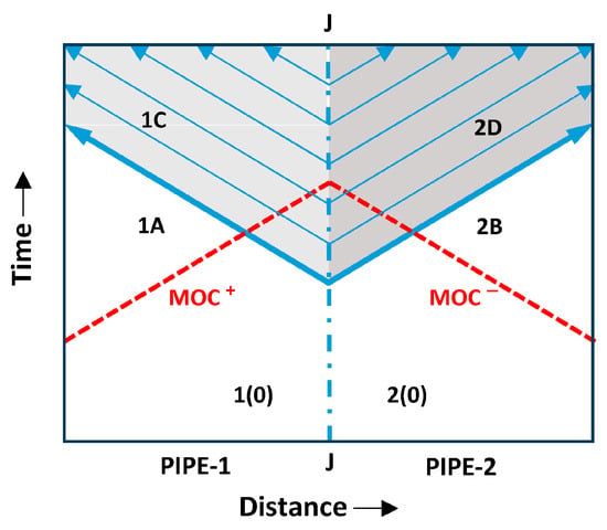
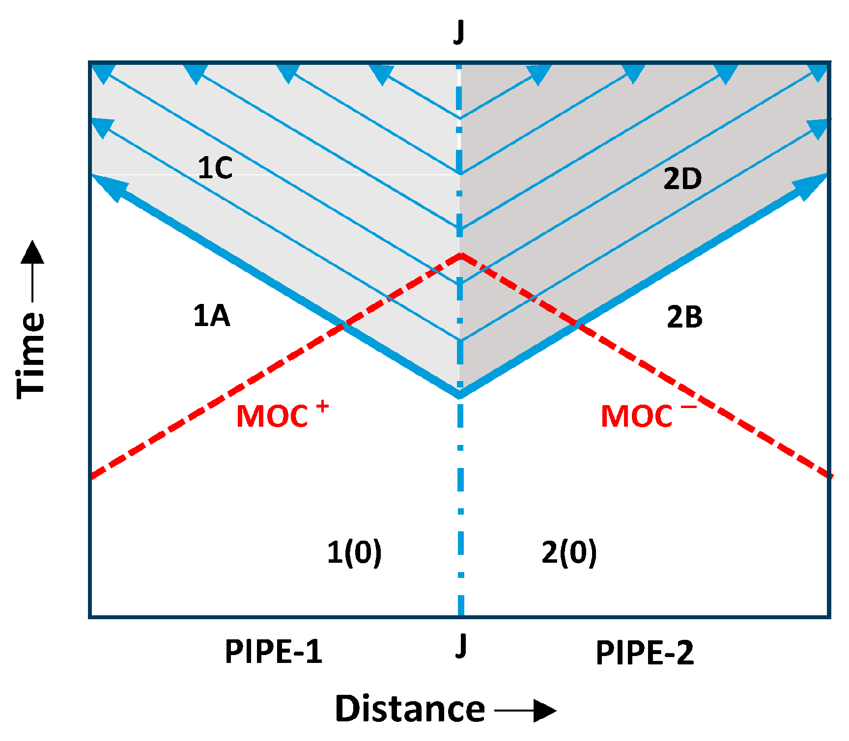
Figure 5 depicts a wavefront propagating along pipe 1 and reaching a bend (J) at which it partially reflects and partially transmits into pipe 2. In pipe 1, three regions of z-t space are identified, namely 1(0) = the initial (steady-flow) conditions, 1A = after the wavefront, but before its reflection from the bend arrives, and 1J = after the reflection. In pipe 2, only two regions exist, namely, 2B = 2(0) = 1(0) before the transmitted wavefront, and 2J after the transmitted wavefront. The figure also shows typical wave paths in both pipes before and after the incident wavefront reaches the bend.
Figure 5.
Wave paths depicting reflection and transmission at an internal boundary (J). Wave generated at t = 0 at the far end of pipe 1.
For completeness, it is useful to note that, as described in Section 2 in the context of fixed bends, in pipe 1, H1J < H1A implies that V1J > V1A, whereas in pipe 2, it implies that V2J < V1A. For the fixed-bend case, this violated mass conservation. For the moving-bend case, however, it acts as a measure of the storage effect of the movement, see Figure 3a.
Using the Method of Characteristics (MOC), the following equations describe the changes across the reflected and transmitted wavefronts.
In the idealized fixed-bend example, the flow states in the regions 1J and 2J are equal. When the bend is free to move, however, these states are not equal. Herein, they are deemed to satisfy the following boundary conditions, in which denotes the axial velocity of a pipe wall.
Equations (2) and (3) can be combined to give the following expressions for the velocities and pressure head at the bend after the reflection/transmission process:
Assuming zero initial conditions in both pipes (i.e., H = 0 and V = 0) and noting that Equation (3, bottom) gives , Equation (4) reduce to (t > L1/a):
4.3. Bend Allowed to Move in Only One Axial Direction:
Equation (5) relate the four unknowns V1J, V2J, HJ and . To proceed further, it is necessary to infer information about the structural velocities, and this necessitates consideration of external structural restraints as well as internal forces. At one extreme, namely the fixed bend considered above, the external (anchor) forces are deemed to be so great that the bend cannot move. We now consider the opposite extreme, namely a bend with no nearby external support [3,20]. This is a good approximation to reality in many applications with suspended pipework. In this section, the bend is free to move in the axial direction of pipe 1 but is prevented from moving in the axial direction of pipe 2. That is, , as illustrated in Figure 3a. In Section 4.5, it is free to move in both directions.
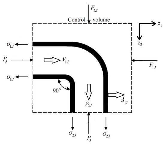
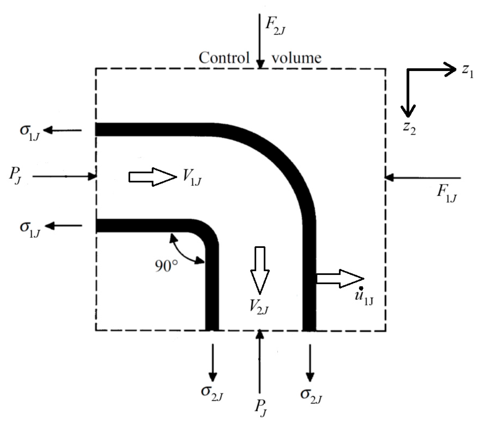
The control volume shown in Figure 6 includes a 90° bend that is deemed to be rigid, so that no account needs to be taken of its flexibility. The control volume is stationary relative to the coordinate axes, so the momentum equation in the axial z1 direction after the wavefront has passed through the bend is
in which Aw is the cross-sectional area of the pipe wall, is the axial stress, m is the mass of fluid in the control volume and mw the mass of the elbow. No account is taken of shear or inertial forces associated with bending in pipe 2. With (temporarily) constant PJ and σ1J, the conditions are steady so that the first term on the right-hand-side of Equation (6) is zero. The second term on the right is a convective term which normally is disregarded in waterhammer analysis. The reaction force F1J is 0 (unrestrained bend), so the axial stress in the wall satisfies
and the associated axial strain ε1J is
where E is the Young’s modulus of the wall material. This strain exists along the whole length of the region between the bend and the stress-wavefront induced in the wall by the reflection and transmission of the incident pressure wavefront. The length of that region is increasing at approximately the speed of sound in the wall, namely, aw = √(E/ρw), where ρw is the density of the wall material, so the induced bend velocity (derived via “Joukowsky”: = ρw aw ) is
Figure 6.
Stationary control-volume surrounding the bend.
Since is deemed to be zero, the values of HJ, V1J and can now be obtained by solving Equations (5, top and bottom) and (9) simultaneously, and the value of V2J then follows from Equation (5, middle).
It is acknowledged that, although there are no externally imposed forces in the z1 direction in this example, the assumption of zero structural resistance to the movement of pipe 1 is not exactly correct. The axial movement of pipe 1 is resisted by bending in pipe 2. The shear force that is needed in this pipe to cause this corresponds to an axial force in pipe 1, and a further axial force is required to overcome associated inertial forces. Although a shear force in pipe 2 will reduce the axial velocity , the bend is mostly held in position by the nearest rigid support of pipe 1. The stress-wave reflected from this support will pull the bend back.
4.4. Cartwright’s Test Problem with Fluid-to-Structure Coupling
The following test problem is a variation of one discussed by Cartwright (1977) [13]. His two-way FSI model explored waterhammer waves interacting with a ‘lumped’ pipe system (i.e., the bend and connected piping were represented by a spring-mass k-m system, see Figure 7) as applied by Wood & Chao (1971) [21], Wiggert et al. (1985) [22], Khalighi et al. (2024) [23]. In such models, the moving bend’s mass and elastic support are estimated values; there are no waves propagating in the pipe walls. In this instance, the interaction is one-way FSI (fluid-to-structure) and the bend is free to move only in the direction of the axis of pipe 1. In Section 5.2, one-way FSI (structure-to-fluid) is considered for the same pipework. The pipe data are as follows: length L1 = L2 = 10 m and internal diameter D = 0.0762 m (i.e., 3 inch), giving a flow area of A = 4.56·10−3 m2. The selected lowest mass (in Cartwright’s 24 test cases) is m = 40 kg; so, for a density of ρw = 7850 kg/m3 (present authors’ estimate) and rigid-body pipe 1 motion, the wall area is Aw = m/(ρw L1) = 5.1·10−4 m2, implying a wall thickness of approximately e = Aw/(π D) = 2.1 mm. The selected lowest stiffness is k = 105 kg/s2 (of importance in Section 5.2). The waterhammer wave speed was estimated as approximately a = 1280 m/s.
Figure 7.
Spring-mass system according to Cartwright 1977 ([13], Figure 10.8).
In Cartwright’s example, the initial condition is stationary pipework conveying a steady water flow with a high velocity V0 of 5 m/s. This requires the pipe system to be anchored in some manner to resist the fluid-momentum forces at the bend. Inviscid flow is assumed and all subsequent values of the liquid and structural parameters are expressed relative to these initial conditions. For reasons that will become clear in the next paragraph, the prescribed initial flow is in the negative axial directions, i.e., from inlet at the +z2 end of pipe 2 to outlet through a valve at the −z1 end of pipe 1; this is compliant with the direction of the pressure wave depicted in Figure 1.
A valve at the outlet from pipe 1 is now closed instantaneously, causing a Joukowsky pressure head of H = a V0/g = 652 m (with g = 9.81 m/s2). This implies a huge pressure force on the valve, namely, F = P A = ρ g A H = 29.2 kN (with ρ = 1000 kg/m3). Nevertheless, neglecting Poisson’s ratio effects, the stipulation that the valve does not move ensures that no axial stresses are induced in the pipe wall. Therefore, the resulting behaviour (relative to the initial conditions), is as described by Equations (5) and (9) for the special case of initially zero flow. Using Equation (7), the axial stress induced in the pipe wall (by pressure-wave impact at the bend) is σ1J = F/Aw = 57 MPa and, using a Young’s modulus of E = 200 GPa (present authors’ estimate), the corresponding strain is ε = σ1J/E = 0.00029. The implied speed of sound in the pipe wall is aw = √ (E/ρw) = 5050 m/s, so the velocity of the bend given by Equation (9) is = 5050·0.00029 = 1.5 m/s (derived via “Joukowsky”: = ρw aw ). This velocity remains constant for a period of ∆t = 2 L1/aw = 4.0 ms, during which, the pipe extends by ∆t = 2 L1 ε = 5.8 mm. Note that the displacement is twice its static value L1 ε, which is one argument for the common use of dynamic load factors of 2. The value of 5.8 mm is used in Section 5.2 to assist in the choice of a suitable initial displacement in forced-vibration and snap-back tests. In mechanics, a snap-back test is a dynamic testing method where a pre-loaded structure is suddenly released to induce free vibration, to study stiffness, damping, and unexpected behaviour (due to cracks and other faults).
4.5. Bend Allowed to Move in Both Axial Directions:
We now consider the more probable case of a bend that is free to move in both directions, z1 and z2, as sketched in Figure 8.
Figure 8.
Deflected bend according to Cartwright 1977 ([13], Figure 10.13).
Equations (7)–(9) are valid for this case too, and the corresponding equations for pipe 2 are as follows:
The values of HJ, and can be obtained by solving Equations (5, bottom), (9) and (10, bottom) simultaneously, and the values of V1J and V2J then follow from Equation (5, top, middle).
The different signs of and in Equations (9) and (10, bottom) arise because the positive directions of both axes (z1 and z2) correspond with the direction of flow whereas the directions of bend movement are determined by the forces in the pipe walls that cause the pipes to extend (see Figure 6).
It is noted in passing that, for the particular case under discussion, the geometrical and mechanical properties of the two pipes are identical, so the absolute values of and are equal. Therefore, and so the only adjustment that would need to be made to Equation (5) to make them suitable for this more general case is the replacement of by . Naturally, this simple substitution is appropriate only for the particular case of a 90° bend in a uniform pipe.
4.6. Swaffield’s Experiments
Swaffield’s test rig and basic data are shown in Figure 2 above. The geometrical data for the polythene (PE) pipes are as follows: L1 = 22 ft = 6.7 m, L2 = 18 ft = 5.5 m (18 feet in Figure 2a, but 19 feet on page 606 in [2]), and D = 2 inch = 0.051 m. The wall thickness is not stated. The pipe-wall properties are ρw = 930 kg/m3 and E = 0.5 GPa, so, neglecting Poisson coupling, the speed aw of sound in the walls would be 733 m/s.
The water properties are ρ = 1000 kg/m3 and K = 2.1 GPa, implying a speed of sound in an unconfined medium of a = √ (K/ρ) = 1449 m/s. It is difficult to infer the actual wave speed, allowing for the pipe’s radial flexibility, because some conflicts exist in Swaffield’s paper [2]. For example, Figure 2 in that paper gives 2L2/a = 32 ms, which implies a = 343 m/s, whereas his Figure 6 gives 2L2/a = 46 ms, which implies a = 239 m/s.
Some clues to the true speed can be obtained by considering measured flow parameters. Based on Figure 2 in [2], the initial flow velocity was V0 = 3.1 ft/s = 0.95 m/s and the resulting pressure rise at the downstream valve in pipe 2 was ΔP = 29.3 lbf/in2 = 202 kPa. Using these values and an estimated wall thickness e = D/10, the Joukowsky equation gives a = ΔP/(ρ V0) = 214 m/s where Korteweg’s expression gives a = √ (K/ρ)/√ (1 + (D/e) K/E)) = 221 m/s. The numerical values in the following paragraph are based on a nominal wave speed of a = 214 m/s.
Swaffield observed pressure reflections of up to 16% of ΔP from 90° bends in both polythene and steel pipes. To assess the implications of this for inferred bend motion, consider an initial condition of steady, frictionless flow with a velocity of V0 and a gauge pressure of zero. Sudden closure of an immovable valve (at the end of pipe 2 as in Figure 2a) would cause a pressure wave that reduces the velocity to zero and increases the pressure by ΔP = ρ a V0. If a reflected wave from the bend then reduces the pressure by 16%, it must also cause a velocity increase of 0.16 ΔP/(ρ a) in the original direction of the wave—i.e., in pipe 2 towards the bend. To infer what this implies about the bend motion, we must first consider the wave transmitted into pipe 1. Assuming continuity of pressure at the bend, the amplitude of this transmitted wave is 0.84 ΔP so the induced velocity will be 0.84 V0. That is, the fluid velocity in pipe 1 towards the bend exceeds the fluid velocity in pipe 2 from the bend by 0.32 V0. Continuity (Equation (3, bottom)) requires (for positive velocity from pipe 1 to pipe 2) the following: .
From symmetry, expressed by Equations (9) and (10, bottom), it follows that , implying net movement at 45° to both axes. Consequently,
It is re-emphasised that this estimate is subject to considerable uncertainty, partly because it is based on uncertain data and partly because the process that has led to it includes a number of assumptions. Nevertheless, unless the result is greatly in error, useful qualitative conclusions can be made. In particular, even if this velocity were maintained for the whole of the time 2L1/aw required for stress waves in the pipe wall to travel back and forth, namely, approximately 18 ms, the total movement would be only about 0.4 mm (18 ms times 21 mm/s). Thus, the displacements implied by the measured deflections are so small (and so short-lived) that there is no wonder that Swaffield originally believed it to be reasonable to regard the bend as fixed. An important corollary of this inference is that it will be easy for engineers who are not fully aware of this aspect of FSI to repeat Swaffield’s mistake even when they actively try not to do so.
5. Analysis: Structure-Induced Disturbances in the Fluid
Attention now turns to one-way ‘pipe to fluid’ FSI, in which a prescribed external vibration of a bend causes pressure waves in the contained liquid. To enable these to be seen clearly, all other possible causes of pressure waves are excluded. Likewise, in common with the fluid-to-structure cases, all possible causes of damping are excluded.
5.1. Bend Allowed to Move in One Axial Direction (z1)
The assessment begins with the particular case of a bend that is prevented from moving in the z2 direction and is acted on by structural forces that induce a harmonic vibration on the z1 axis at the bend (Figure 3a):
in which ω denotes the angular frequency and U the amplitude of displacement. Note that the displacement and velocity are 90° out of phase and that ω = 0 describes a rigid (fully anchored) bend. In the following development, both U and ω are regarded as prescribed values. This causes—if the frequency is high enough—pressure waves to propagate along both pipes. They will do so without change of form (d’Alembert’s principle) until reaching the remote ends of the pipes.
In the following development, the liquid is initially at rest (V0 = 0) and the pressure is uniform (H0 = 0). At some instant, the external structural excitation is suddenly switched on and begins to induce pressure disturbances in both pipes. The pipes are deemed to be infinitely long (i.e., as in the experimental results presented by Swaffield [2], no reflections occur in the time window considered), so all wave propagation in them is exclusively in the direction away from the bend. Figure 9 depicts the wave propagation in (z-t) space.
Figure 9.
Wave paths depicting symmetric propagation in pipes 1 and 2. Snap-back starts at t = 0 at the bend (J).
5.1.1. Time-Domain Analysis
With as defined in Equation (12) and = 0, the MOC Equation (4) become
For the prescribed harmonic disturbance, the conditions in the regions 1C and 2D vary continually, but in both pipes, characteristic paths meeting at the bend (J) can be projected back to the period of zero flow (N.B. compare with Figure 5, in which this is the case only in pipe 2). Then, all of H1A, H1B, V1A and V1B are zero (regions 1A = 1(0) and 1B = 2(0)) so that Equation (13) become the following:
5.1.2. Symbolic Solution for Steady Oscillations in Pipes of Finite Length
Although Equation (14) can be evaluated analytically, they are valid only when all wave propagation is in the directions away from the bend. Then, the characteristic paths can be projected back as far as the time t = 0, at which ambient conditions prevail. This is always possible for pipes of infinite length, but for finite-length pipes, it is possible only during t < 2L/a, where L is the smaller of L1 and L2. Thereafter, the true behaviour at the bend is influenced by the remote boundaries. Solutions can still be obtained using Equation (13) together with the appropriate boundary conditions at the remote ends, but this will usually require the use of a computer.
It is nevertheless possible to obtain information about the bend-induced waves at some later times analytically. In particular, solutions can be developed for the large-time condition after the initial transient behaviour has gradually died away and the overall behaviour has settled down to a steady-oscillating state. This behaviour occurs when the forcing parameter (i.e., the prescribed external harmonic force) is maintained indefinitely. Tijsseling et al. [24,25] obtained a solution for steady oscillations in a single pipe [24] or two pipes in series [25] with constant pressure at one boundary and harmonic pressure or velocity excitation at the other boundary. That is,
Reflected and transmitted pressures and flows in pipes 1 and 2 interact at the bend where z1 = L1 and z2 = 0. If L1 = L2 = L, and the remote-end conditions are the same (Equation (15)), one can use symmetry: V1J = −V2J. The pipe 1 solution for this case is as follows:
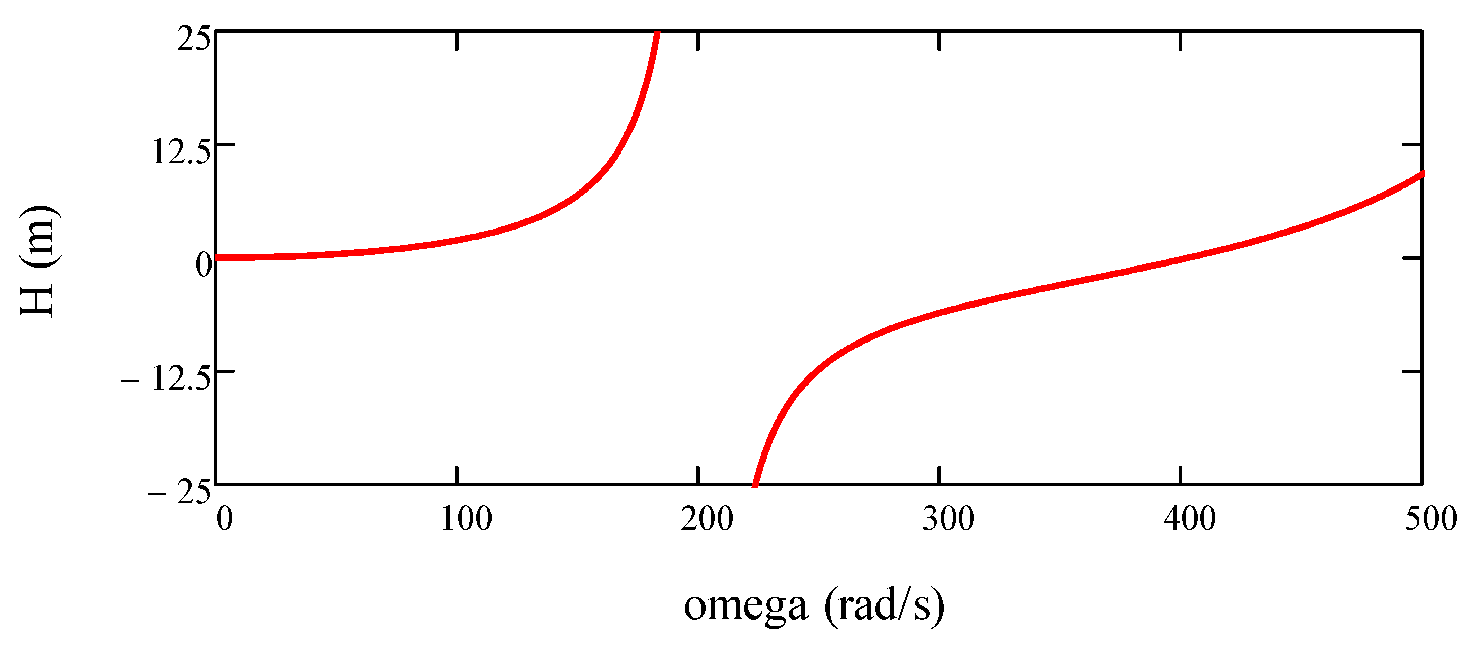
By inspection, at the bend (z1 = L, z2 = 0), the fluid velocities (Equation (16)) are the same as those in the example without reflected waves (Equation (14, top). However, the pressures in the two cases are different (Equations (14, bottom) and (17)). In the steady-oscillating state, they are modulated by tan(ωL/a). The amplitude of the steady oscillations depends on the driving frequency. In the special case when ωL/a = π/2, the denominator in Equation (17) is zero and resonance occurs. The absolute frequency corresponding to this case is f = ω/(2 π) = a/(4L).
5.2. Cartwright’s Test Problem with Structure-to-Fluid Coupling
The basic data for the following case are the same as those used for the corresponding valve-closure simulation in Section 4.4. The bend has a prescribed harmonic motion due to a small initial displacement in the positive z1 direction.
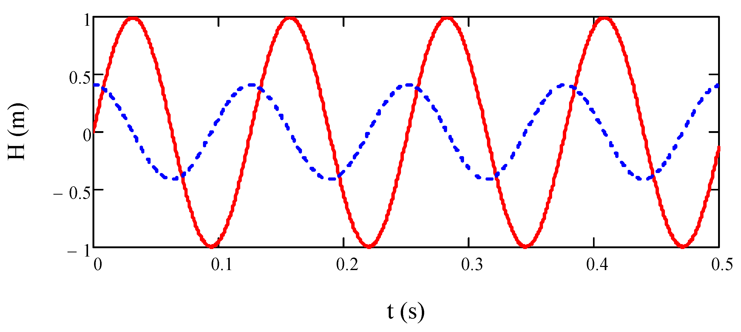
To ensure realistic behaviour, the chosen amplitude of the maintained forced harmonic vibration is U = 0.3 mm, which is approximately 5% of the one-off displacement estimated in the valve-closure case in Section 4.4. The angular frequency, estimated from Cartwright’s fundamental spring-mass system, is ω = √(k/m) ≈ 50 Hz, so the absolute frequency f = ω/(2π) ≈ 8 Hz. Using Equation (14, bottom), the amplitude of the bend-motion-induced pressure head without reflections is a ω U/(2 g) ≈ 1 m. With U = 5.8 mm, the amplitude of the pressure head is about 20 m, which is small in comparison with the Joukowsky head of 642 m obtained in the valve-closure case (without valve motion).
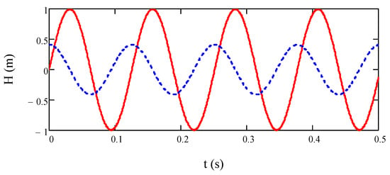
Figure 10 compares pressure fluctuations obtained for this case. The continuous line shows early time behaviour given by the MOC solution—Equation (14, bottom)—and is applicable only before reflections begin to arrive from the remote ends of the pipes. The broken line shows the large-time behaviour given by the symbolic solution, allowing for the finite lengths of the pipes—Equation (17) for z1 = L. For this particular case, the large-time amplitudes (with reflections from far ends) are more than twice smaller than the small-time ones (without any reflections).
Figure 10.
Pressure head oscillations at the bend induced by structural excitation with an amplitude of 0.3 mm and a frequency of 50 Hz (steel pipe, L1 = L2 = L = 10 m). Continuous line = small time: before reflections from remote ends. Broken line = large times: steady oscillating flow.
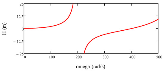
This behaviour is broadly representative of that corresponding to many frequencies of excitation, but it will clearly not be so when the frequency of the forced structural excitation is close to a resonance frequency. This is illustrated in Figure 11, which shows the dependency of the maximum pressure head on the imposed frequency. In this example, the resonance frequency f = a/(4L) = 1280/40 = 32 Hz and the angular frequency is ω = 2π f = 201 rad/s.
Figure 11.
Dependence of the amplitude of the pressure head on the forcing’s angular frequency; large-time behaviour.
In principle, symbolic steady-oscillatory solutions can be obtained for the L1 ≠ L2 case (Swaffield’s system) as well, but this is outside the scope of this paper.
6. Conclusions
To a close approximation, waterhammer waves do not ‘see’ immovable bends in uniform pipes: they simply pass through them. Tiny reflections due to minor losses can exist but are unlikely to be detectable in practical applications. However, waterhammer waves are commonly strong enough to make a bend move, and in the case of positive waves, this causes negative reflections that will be detectable. The resulting behaviour has been discussed and has been analysed in a simple manner by disregarding potential influences of secondary effects such as damping and rotation. The analysis is of practical use because the early time responses of the pipework when pressure waves pass through a bend are not strongly influenced by secondary effects. The analysis of this case has been undertaken allowing for two-way FSI.
The influence of externally forced vibration of bends on induced pressure waves has also been assessed, in this case by simulating the behaviour as only one-way FSI (structure to fluid). Again, secondary effects have been neglected because they have only a small influence on the initial responses of the fluid, although they can be important if the vibrations induce resonance.
The motion of bends can be deduced from reflections observed in measured pressure signals, by a sort of inverse analysis (assessing structural stiffness). In this way, the transient bend displacement in Swaffield’s classical experiments [2] has been estimated to have been no greater than 0.4 mm in a 6 m long pipe, something barely visible to the human eye.
In closing, we note that the type of resonance predicted by one-way FSI models (fluid-to-structure) will not exist in practice because of two-way effects that exist because of stress waves that are induced simultaneously with the pressure waves [26] Wiggert & Tijsseling (2001). However, one-way coupling at bends and other junctions is nevertheless informative and it is easily implemented as a capacitance element (Figure 3a) in professional waterhammer software such as AFT Impulse, ALLIEVI, ARIETE, ARTS, Bentley HAMMER, BOSFluids, CEBELMAIL, DRAKO, DSHplus, DYAGATS, EPA SURGE, FLOW 3-D, FLOWMASTER 2, H2O SURGE, HYPRESS, HYTRAN, KYPIPE, LIQT, MIKE URBAN, PIPENET, SENARIET, SIR 3S, SURGE, Synergi Pipeline Simulator, TRANSAM, TSNet, uSLAM, WANDA, WH, and WHAMO.
Author Contributions
Conceptualization, A.S.T.; Investigation, C.J.B.C.; Writing, review and editing, A.E.V. All authors have read and agreed to the published version of the manuscript.
Funding
This research received no external funding.
Data Availability Statement
Acknowledgments
This Technical Note is based on a presentation held by the first author at the 40th IAHR World Congress, Vienna (2023), session IAHR_6_S1: Transient Flows. Kanayochukwu Ibiam of Magdeburg-Stendal University of Applied Sciences is thanked for preliminary numerical simulations of bend motion within waterhammer MOC.
Conflicts of Interest
The authors declare no conflicts of interest.
Nomenclature
| A | area (m2) |
| a | wave speed (m/s) |
| D | pipe inner diameter (m) |
| E | Young modulus (Pa) |
| e | pipe wall thickness (m) |
| F | force (N) |
| f | frequency (Hz) |
| g | gravitational acceleration (m/s2) |
| H | pressure head (m) |
| K | bulk modulus (Pa) |
| k | stiffness (N/m) |
| L | pipe length (m) |
| m | mass (kg) |
| P | pressure (P) |
| t | time (s) |
| U | maximum displacement of bend (m) |
| u | displacement of bend (m) |
| velocity of bend (m/s) | |
| V | velocity of fluid (m/s) |
| z | axial distance (m) |
| Δ | change, finite difference |
| ε | axial strain |
| ρ | mass density (kg/m3) |
| σ | axial stress (Pa) |
| ω | angular frequency (rad/s) |
| Subscripts | |
| A, B | earlier positions along characteristic lines in the distance–time plane |
| J | junction |
| w | wall |
| 0 | initial |
| 1 | connection of pipe 1 and bend |
| 2 | connection of pipe 2 and bend |
References
- Contractor, D.N. The reflection of waterhammer pressure waves from minor losses. ASME J. Basic Eng. 1965, 87, 445–451, discussion 451–452. [Google Scholar] [CrossRef] [Scilit]
- Swaffield, J.A. The influence of bends on fluid transients propagated in incompressible pipe flow. Proc. Inst. Mech. Eng. 1968–1969, 183, 603–609, discussion 609–614. [Google Scholar] [CrossRef] [Scilit]
- Tijsseling, A.S. An overview of fluid-structure interaction experiments in single-elbow pipe systems. J. Zhejiang Univ. Sci. A 2019, 20, 233–242. [Google Scholar] [CrossRef] [Scilit]
- Wiggert, D.C. Coupled transient flow and structural motion in liquid-filled piping systems: A survey. In Proceedings of the ASME Pressure Vessels and Piping Conference, Chicago, IL, USA, 20–24 July 1986; Paper 86-PVP-4; ASME: New York, NY, USA, 1986. [Google Scholar]
- Leslie, D.J.; Tijsseling, A.S. A review of modelling damping mechanisms in coupled liquid-pipe vibrations. In Proceedings of the 3rd ASME & JSME Joint Fluids Engineering Conference, Symposium S-290 Water Hammer, San Francisco, CA, USA, 18–23 July 1999; Liou, J.C.P., Ed.; Paper FEDSM99-6878; ASME-FED: New York, NY, USA, 1999; Volume 248, Available online: https://www.researchgate.net/publication/293235462_A_review_of_modelling_damping_mechanisms_in_coupled_liquid-pipe_vibrations (accessed on 17 February 2026).
- Vardy, A.E. On sources of damping in water-hammer. Water 2023, 15, 385. [Google Scholar] [CrossRef] [Scilit]
- Wylie, E.B. Unsteady internal flows—Dimensionless numbers & time constants. In Proceedings of the 7th International Conference on Pressure, Harrogate, UK; Boldy, A., Ed.; BHR Group: Harrogate, UK, 1996; pp. 283–288. [Google Scholar]
- Itō, H. Pressure losses in smooth pipe bends. ASME J. Basic Eng. 1960, 82, 131–140, discussion 140–143. [Google Scholar] [CrossRef] [Scilit]
- Smyk, E.; Stopel, M.; Szyca, M. Simulation of flow and pressure loss in the example of the elbow. Water 2024, 16, 1875. [Google Scholar] [CrossRef] [Scilit]
- Bergant, A.; Tijsseling, A.S.; Vítkovský, J.P.; Covas, D.I.C.; Simpson, A.R.; Lambert, M.F. Parameters affecting water-hammer wave attenuation, shape and timing. Part 2: Case studies. IAHR J. Hydraul. Res. 2008, 46, 382–391. [Google Scholar] [CrossRef] [Scilit]
- Florence, A.L. Pulse propagation in fluid-filled pipes. In Proceedings of the Third International Conference on Structural Mechanics in Reactor Technology, SMiRT3, London, UK, 1–5 September 1975; Paper F 4/8. Available online: https://repository.lib.ncsu.edu/server/api/core/bitstreams/6671d48f-26a2-4ca3-b1ee-5a2206e88798/content (accessed on 17 February 2026).
- Youngdahl, C.K.; Kot, C.A.; Valentin, R.A. Pressure transient analysis of elbow-pipe experiments using the PTA-2 computer code. ASME J. Press. Vessel. Technol. 1981, 103, 33–42. [Google Scholar] [CrossRef] [Scilit]
- Cartwright, C.J.B. Pressure Transient Reflections at Pipe Bends. Ph.D. Thesis, Department of Civil Engineering, The University of Leeds, Leeds, UK, 1977. [Google Scholar]
- Vardy, A.E.; Tijsseling, A.S. On Boussinesq and Coriolis coefficients and their derivatives in transient pipe flows. Appl. Math. Model. 2022, 111, 454–470. [Google Scholar] [CrossRef] [Scilit]
- Martin, P.A. Going round the bend: Reflection and transmission of long waves by waveguide corners and labyrinths. Proc. R. Soc. A Math. Phys. Eng. Sci. 2023, 479, 20230635. [Google Scholar] [CrossRef] [Scilit]
- Wilkinson, D.H. Dynamic response of pipework systems to water hammer. In Proceedings of the 3rd International Conference on Pressure Surges, Canterbury, UK, 25–27 March 1980; BHRA: Cranfield, UK, 1980; pp. 185–202. [Google Scholar]
- Wylie, E.B.; Streeter, V.L. Fluid Transients in Systems; Prentice Hall: Englewood Cliffs, NJ, USA, 1993. [Google Scholar]
- Belytschko, T.; Karabin, M.; Lin, J.I. Fluid-structure interaction in waterhammer response of flexible piping. ASME J. Press. Vessel. Technol. 1986, 108, 249–255. [Google Scholar] [CrossRef] [Scilit]
- Belytschko, T.; Lin, J.I.; Csay, C.-S. Modal recovery methods for solution of fluid-structure problems with rigid wall loads. Nucl. Eng. Des. 1982, 71, 67–78. [Google Scholar] [CrossRef] [Scilit]
- Tijsseling, A.S.; Vardy, A.E.; Fan, D. Fluid-structure interaction and cavitation in a single-elbow pipe system. J. Fluids Struct. 1996, 10, 395–420. [Google Scholar] [CrossRef] [Scilit]
- Wood, D.J.; Chao, S.P. Effect of pipeline junctions on water hammer surges. ASCE Transp. Eng. J. 1971, 97, 441–456. [Google Scholar] [CrossRef] [Scilit]
- Wiggert, D.C.; Otwell, R.S.; Hatfield, F.J. The effect of elbow restraint on pressure transients. ASME J. Fluids Eng. 1985, 107, 402–406, discussion 108, 121–122. [Google Scholar] [CrossRef] [Scilit]
- Khalighi, F.; Ahmadi, A.; Keramat, A.; Tijsseling, A.S.; Zecchin, A.C. An efficient estimation of fluid–structure interaction in blocked L-shaped pipelines. Iran. J. Sci. Technol. Trans. Mech. Eng. 2024, 48, 1777–1795. [Google Scholar] [CrossRef] [Scilit]
- Tijsseling, A.S.; Hou, Q.; Svingen, B.; Bergant, A. Acoustic resonance in a reservoir-pipeline-orifice system. In Proceedings of the ASME 2010 Pressure Vessels and Piping Division Conference, Bellevue, WA, USA, 18–22 July 2010; Paper PVP2010-25083; ASME: New York, NY, USA, 2010. [Google Scholar] [CrossRef] [Scilit]
- Tijsseling, A.S.; Hou, Q.; Svingen, B.; Bergant, A. Acoustic resonance in a reservoir—double pipe—orifice system. In Proceedings of the ASME 2012 Pressure Vessels and Piping Division Conference, Toronto, ON, Canada, 15–19 July 2012; Paper PVP2012-78085; ASME: New York, NY, USA, 2012. [Google Scholar] [CrossRef] [Scilit]
- Wiggert, D.C.; Tijsseling, A.S. Fluid transients and fluid-structure interaction in flexible liquid-filled piping. ASME Appl. Mech. Rev. 2001, 54, 455–481. [Google Scholar] [CrossRef] [Scilit]

Disclaimer/Publisher’s Note: The statements, opinions and data contained in all publications are solely those of the individual author(s) and contributor(s) and not of MDPI and/or the editor(s). MDPI and/or the editor(s) disclaim responsibility for any injury to people or property resulting from any ideas, methods, instructions or products referred to in the content. |
© 2026 by the authors. Licensee MDPI, Basel, Switzerland. This article is an open access article distributed under the terms and conditions of the Creative Commons Attribution (CC BY) license.