


Abstract
Gel polymer electrolytes (GPEs) require high room-temperature ionic conductivity and stable electrochemical properties to replace conventional liquid electrolytes. In this study, the content of 3-(1-vinyl-3-imidazolio)propanesulfonate (VIPS) was varied from 0 to 10 wt.% in a fluorinated gel polymer electrolyte with a fixed poly(ethylene glycol) diacrylate (PEGDA) and 2,2,2-trifluoroethyl methacrylate (TFEMA) host. Adding 5 wt.% VIPS increased the temperature at which the gel lost 10% of its initial mass from 238 to 266 °C. Also at 25 °C, the ionic conductivity increased from 2.10 mS cm−1 for the VIPS-free gel to 4.88 mS cm−1 at 5 wt.% VIPS and the oxidative onset potential also improved from 4.80 to 5.15 V (vs. Li/Li+). The optimized GPE with 5 wt.%, named ZF-GPE-V5, shows stable lithium plating and stripping behavior over 1000 h. An LFP|ZF-GPE-V5|Li cell recovered 99.50% of its initial low-rate discharge capacity after operation at 1.0 C and retained 87.16% of its initial capacity after 200 cycles at 0.2 C. These results suggest that the appropriate application of zwitterion-functionalized monomers can serve as a bridging technology between conventional batteries and future all-solid-state batteries.
1. Introduction
Lithium metal is an attractive anode material for next-generation rechargeable batteries because of its high theoretical specific capacity (3860 mAh g−1) and low standard electrode potential (−3.04 V vs. SHE). Replacing graphite with lithium metal could increase cell-level energy density, particularly in cells with high-capacity or high-voltage cathodes. However, repeated lithium plating and stripping lead to continuous changes in electrode morphology and the solid electrolyte interphase (SEI). Nonuniform ion flux and locally elevated current densities can promote uneven lithium deposition, while repeated SEI disruption exposes fresh lithium to the electrolyte, driving further parasitic reactions. These processes can result in porous deposits, electrically isolated lithium, electrolyte depletion, and internal short circuits, limiting the reversibility and long-term stability of lithium-metal batteries [1,2,3,4,5,6,7]. To address these challenges, solid polymer electrolytes have been widely investigated as alternatives to conventional liquid electrolytes because they offer low volatility, mechanical flexibility, and the potential for conformal electrode contact. However, many polymer electrolytes exhibit limited ionic conductivity at room temperature (RT), particularly when slow polymer segmental motion limits ion transport and crystalline domains impede it [8,9]. Gel polymer electrolytes (GPEs) combine a liquid electrolyte with a cross-linked or physically entangled polymer network. The liquid phase facilitates ion transport, while the polymer network retains the liquid and provides structural support. This combination can yield room-temperature ionic conductivities close to those of liquid electrolytes while reducing leakage and maintaining the processability of polymer-based systems [10,11,12,13]. Researchers have explored in situ polymerization as a means of improving interfacial contact in GPE-based cells. This approach allows liquid precursors to infiltrate porous electrodes and separators before forming a polymer network, thereby improving electrode–electrolyte contact and reducing interfacial voids that contribute to an increase in resistance [14,15].
Researchers have explored several GPE design strategies to improve ion transport and electrode compatibility. Lu et al. prepared a lithium-containing zwitterionic poly(ionic liquid) by photopolymerizing an imidazolium-based complex, using propylene carbonate to promote Li+ transport through ion-dipole interactions [16]. Li et al. incorporated zwitterionic groups into a gel electrolyte to coordinate Li+ and restrict anion migration [17]. Chen et al. formed a supramolecular network using photopolymerization and quadruple hydrogen bonding to balance mechanical strength and ion transport [18]. Fluorinated interphase-forming electrolytes and fluorinated PEGDA networks have also been investigated to improve the interfacial and electrochemical stability of GPE-based batteries [19,20]. Specifically, Liu et al. used 2,2,2-trifluoroethyl methacrylate (TFEMA) as the monomer and PEGDA as the cross-linker in a gel electrolyte. They found that the fluorinated side chains of the polymer interacted with the solvent, ethyl 3,3,3-trifluoropropanoate, and weakened its coordination to Li+. A Li symmetric cell containing this gel sustained lithium plating and stripping for at least 1500 h at 0.5 mA cm−2, whereas a control cell in which TFEMA was replaced with an equal amount of PEGDA short-circuited after 236 h [21]. These studies demonstrate the benefits of zwitterionic regulation, supramolecular reinforcement and fluorination in GPE design. However, simultaneously achieving high room-temperature ionic conductivity, improved selectivity for Li+ transport, oxidative stability, and stable electrode compatibility within a cross-linked GPE remains challenging. When TFSI− or other anions carry a large fraction of the ionic current, high total ionic conductivity does not necessarily ensure efficient Li+ transport. During continuous polarization, this transport imbalance generates salt concentration gradients, increases voltage hysteresis and promotes nonuniform lithium deposition [22,23,24,25,26]. At high potentials, residual carbonate solvents and unreacted polymerizable species can also undergo oxidative decomposition, whereas weak solvent–polymer interactions can result in solvent volatilization or redistribution. In addition, while increasing the cross-link density improves structural stability, it can restrict polymer chain motion and ionic mobility. Therefore, an effective GPE should balance ionic transport, Li+ selectivity, polymer-phase dynamics, oxidative stability and electrode compatibility. Polymerizable ionic liquid and zwitterionic monomers provide charged groups that remain fixed within the polymer network. Their local electric fields can modify ion coordination, promote lithium salt dissociation and reduce the effective mobility of counteranions [16,27,28,29,30,31,32]. In particular, sulfonate groups can provide transient coordination sites for Li+, while imidazolium groups can interact with TFSI−. Fluorinated methacrylates complement these groups because their electron-withdrawing groups can improve anodic stability [33,34,35]. A flexible PEGDA network can provide structural cross-linking and coordination sites on ether oxygens while maintaining sufficient segmental motion for ion transport [36,37]. The combination of these functional monomers is therefore expected to provide a practical balance of ionic conductivity, Li+ selectivity and electrochemical stability.
In this work, we prepared a ternary copolymer GPE (ZF-GPE) by in situ thermal copolymerization of PEGDA, TFEMA and VIPS. Building on earlier studies of zwitterionic copolymer and PEGDA-cross-linked fluorinated gel electrolytes [20,29], VIPS was used here as a functional comonomer in a flexible fluorinated network. The VIPS content varied systematically from 0 to 10 wt.% to investigate its effect on thermal behavior, ion-transport properties and ion-transport kinetics. We characterized the GPEs using Fourier transform infrared (FTIR) spectroscopy, differential scanning calorimetry (DSC), thermogravimetric analysis (TGA), temperature-dependent electrochemical impedance spectroscopy (EIS), chronoamperometry (CA), linear sweep voltammetry (LSV), lithium plating and stripping tests, and coin-cell cycling tests.
2. Materials and Methods
2.1. Materials
1-Vinylimidazole (≥99%, Sigma-Aldrich, St. Louis, MO, USA), 1,3-propanesultone (99%, Sigma-Aldrich, St. Louis, MO, USA), lithium bis(trifluoromethanesulfonyl)imide (LiTFSI, battery grade, MTI Corporation, Richmond, CA, USA), 2,2,2-trifluoroethyl methacrylate (TFEMA, ≥98%, TCI, Tokyo, Japan), poly(ethylene glycol) diacrylate (PEGDA, Mn ≈ 700, Sigma-Aldrich, St. Louis, MO, USA), fluoroethylene carbonate (FEC, 98%, Sigma-Aldrich, St. Louis, MO, USA), propylene carbonate (PC, 99.7%, Sigma-Aldrich, St. Louis, MO, USA), 2,2′-azobisisobutyronitrile (AIBN, 98%, Sigma-Aldrich, St.Louis, MO, USA), acetone (99.5%, Samchun, Seoul, Republic of Korea) and LiFePO4 (LFP, MTI Corporation, Richmond, CA, USA) were purchased from the indicated suppliers and used without further purification. Poly(vinylidene fluoride) (PVDF), Super P conductive carbon and N-methyl-2-pyrrolidone (NMP) were used for cathode preparation.
2.2. Synthesis of 3-(1-Vinyl-3-Imidazolio)propanesulfonate (VIPS)
VIPS was synthesized by adapting a reported ring-opening procedure [38]. First, a solution of 1,3-propanesultone (12.24 g, 0.100 mol) in acetone (40 mL) was added dropwise to 1-vinylimidazole (9.41 g, 0.100 mol) in a round-bottom flask under a nitrogen atmosphere. The reaction mixture was stirred at 0 °C for 3 days. The resulting precipitate was collected by filtration and washed thoroughly with acetone to remove unreacted materials and residual impurities. The product was then dried under vacuum at 40 °C for 24 h. The yield of solid VIPS was 89.47% (19.35 g). To confirm the successful synthesis of VIPS, 1H and 13C nuclear magnetic resonance were conducted and chemical shifts are depicted in Figure S1.
2.3. In Situ Synthesis of the Gel Polymer Electrolyte (GPE)
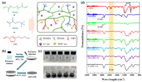
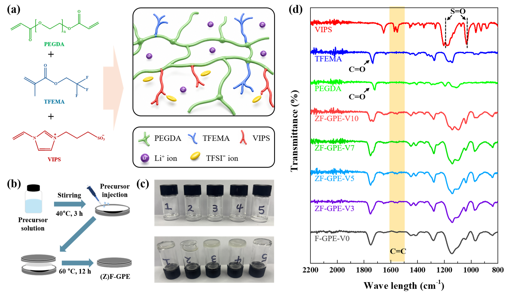
The base liquid electrolyte contained 1 M LiTFSI dissolved in a mixture of FEC and PC (5:95, v/v). As illustrated in Figure 1, 1.0 mL of the base electrolyte was mixed with 200 mg of PEGDA and 1.025 g of TFEMA. The VIPS content was set to 0, 3, 5, 7, or 10 wt.% of the total monomer content (PEGDA + TFEMA + VIPS) mass. AIBN (1.5 wt.% of the total precursor mass) was added as a thermal initiator. Each mixture was stirred at 40 °C for 3 h to obtain a homogeneous precursor solution. Before cell assembly, the glass-fiber separators (GF/A, 19 mm in diameter and 260 µm thick) were dried in a vacuum oven for 24 h. Subsequently, 82 µL of the precursor was dispensed onto a glass-fiber separator and thermally polymerized inside the assembled coin cell at 60 °C for 12 h. All preparation procedures were carried out in an atmosphere with moisture and oxygen levels each below 0.1 ppm. The resulting GPEs were denoted F-GPE-V0, ZF-GPE-V3, ZF-GPE-V5, ZF-GPE-V7 and ZF-GPE-V10, corresponding to VIPS contents of 0, 3, 5, 7 and 10 wt.%, respectively.
Figure 1.
Fabrication and structural characterization of F-GPE-V0 and the ZF-GPE gel polymer electrolytes. (a) Chemical structures of PEGDA, TFEMA, and VIPS, together with a schematic illustration of the cross-linked ZF-GPE network containing Li+ and TFSI−. (b) Schematic illustration of precursor loading, coin-cell assembly, and in situ thermal polymerization. (c) Photographs of F-GPE-V0, ZF-GPE-V3, ZF-GPE-V5, ZF-GPE-V7, and ZF-GPE-V10 before (top) and after (bottom) thermal polymerization. (d) FTIR spectra of the monomers and GPEs with different VIPS contents.
2.4. Cathode Preparation
LFP powder (0.96 g), PVDF (0.12 g) and Super P (0.12 g) were dispersed in 3 mL of NMP to obtain a homogeneous slurry. The slurry was coated onto an aluminum foil current collector and dried under vacuum at 80 °C for 12 h to remove NMP. The dried electrode was punched into discs 13 mm in diameter and used for coin-cell assembly. The thickness of coated cathode layer was 14.47 ± 2.08 µm (n = 10), excluding the aluminum current collector.
2.5. Characterization of Gel Polymer Electrolytes
The chemical structures and in situ thermal copolymerization of the GPEs were examined by Fourier transform infrared (FTIR) spectroscopy. Spectra were recorded for the individual monomers (PEGDA, TFEMA and VIPS) and the cross-linked GPEs containing different amounts of VIPS. Spectra were collected with an IdentifyIR® FTIR spectrometer (Smiths Detection, Hemel Hempstead, UK) equipped with a diamond attenuated total reflectance (ATR) accessory. All spectra were collected from 2200 to 800 cm−1 at a resolution of 4 cm−1, using 256 scans per sample. A background spectrum was recorded before each measurement and subtracted from the sample spectrum. Separator-free gels were prepared with the same formulations for calculation of gel fraction. Weight of prepared gel polymer was measured before and after washing with THF and methanol, and the insoluble polymer was dried.
2.6. Thermal Characterization
The thermal transitions of F-GPE-V0 and the ZF-GPE series were measured using a Jade differential scanning calorimeter (PerkinElmer, Waltham, MA, USA). A 5.00 mg portion of each sample was sealed in an aluminum pan. The sample was first cooled to −50 °C and then heated to 50 °C. It was subsequently cooled to −80 °C and heated to 110 °C at 10 °C min−1. The DSC thermograms were obtained during this second heating scan. Nitrogen gas flow was maintained at 19.8 mL min−1 throughout both heating stages. The reported thermograms are from the second heating scan. The heat-flow signals were normalized and plotted with the endothermic direction upward. For comparison, the DSC thermograms were vertically offset in the order F-GPE-V0, ZF-GPE-V3, ZF-GPE-V5, ZF-GPE-V7 and ZF-GPE-V10, from bottom to top. The transition midpoint was read at half the heat-flow difference between the extrapolated baselines on either side of the low-temperature step.
Thermogravimetric analysis (TGA) was performed using a TGA/N-1000 analyzer (SCINCO, Seoul, Republic of Korea) to evaluate the temperature-dependent mass-loss behavior of the GPE without glass-fiber separators. A 5.00 mg sample was placed in an alumina crucible and heated from 25 to 450 °C at a heating rate of 10 °C min−1 under a nitrogen flow of 40.0 mL min−1. The sample mass was recorded continuously during heating, and the remaining mass was expressed as a percentage of the initial sample mass. The temperatures corresponding to 10% and 50% mass loss, denoted T10% and T50%, respectively, were determined at 90% and 50% of the initial mass and used to compare mass retention during heating across formulations.
2.7. Electrochemical Characterization
The electrochemical properties of the GPEs were measured using a ZIVE MP1 potentiostat (WonATech, Seoul, Republic of Korea).
Ionic conductivity was measured by EIS in SS|GPE|SS cells in which the GPE was placed between two stainless-steel (SS) electrodes, each with an area of 2.84 cm2. The impedance spectra were recorded from 1 MHz to 10 mHz with an AC amplitude of 10 mV at temperatures of 25, 30, 40, 50, and 60 °C. The bulk resistance was obtained from the high-frequency intercept of the Nyquist plot with the real axis. The ionic conductivity was calculated using Equation (1):
where σ is the ionic conductivity, L is the thickness of the gel polymer electrolyte, R is the bulk resistance obtained from EIS and S is the electrode–electrolyte contact area. Ionic conductivity at each temperature is reported as the mean ± standard deviation from three independently assembled cells per formulation. The temperature dependence of ionic conductivity was evaluated using the Arrhenius relationship [39,40] given in Equation (2):
where A is the pre-exponential factor, Ea is the activation energy, R is the universal gas constant (8.314 J·mol−1·K−1) and T is the absolute temperature. Ea was obtained by ordinary least-squares fitting of log10(σ) against 1000/T using data collected at 25, 30, 40, 50, and 60 °C. For a fitted slope m, Ea = −2.303 × R × 1000 × m, with Ea expressed in J mol−1.
Linear sweep voltammetry was performed at 25 °C in SS|GPE|Li cells. The 19 mm stainless-steel disk served as the working electrode and lithium as the combined counter and reference electrode. Current was normalized to the exposed stainless-steel area (2.84 cm2). The potential was swept in the positive direction from approximately 0 V at 1 mV s−1. The operational oxidation onset was defined as the first potential above 3 V at which the current density reached 10 µA cm−2, with linear interpolation between adjacent points [41].
The apparent Li+ transference number (tLi+) was determined by chronoamperometry inLi|GPE|Li symmetric cells, with impedance spectra recorded before and after polarization. The electrode surface area of lithium-metal electrode was 2.01 cm2 (16 mm diameter). A DC polarization voltage of 9.5 mV was applied at 25 °C, and tLi+ was calculated using the Bruce–Vincent equation (Equation (3)) [42,43,44,45]:
where I0 and Iss are the initial and steady-state currents, respectively. ΔV is the applied DC polarization voltage and R0 and Rss are the interfacial resistances measured before and after polarization, respectively.
2.8. Cycling Performance Evaluation
Coin cell experiments were conducted to evaluate the compatibility of the optimized ZF-GPE-V5 electrolyte with lithium metal, as well as its rate capability and long-term cycling performance. All electrochemical measurements were performed using CR2032 coin cells. The compatibility of the electrolytes with lithium metal was investigated using Li|GPE|Li symmetric cells assembled with two 500 µm-thick lithium foils. Long-term lithium plating and stripping tests were conducted using Li|F-GPE-V0|Li,Li|ZF-GPE-V3|Li, and Li|ZF-GPE-V5|Li cells at 25 °C and a current density of 0.1 mA cm−2. The critical current density (CCD) protocol for Li|GPE|Li symmetric cells containing F-GPE-V0, ZF-GPE-V3, or ZF-GPE-V5 started at 0.10 mA cm−2 and increased in increments of 0.05 mA cm−2 to a maximum of 1.00 mA cm−2. Each current step consisted of one complete cycle, with 1 h of lithium plating followed by 1 h of stripping at the same current magnitude. In a separate experiment at 25 °C, a Li|ZF-GPE-V5|Li symmetric cell was cycled sequentially at 0.1, 0.2, 0.3, 0.4, and 0.5 mA cm−2 before returning to 0.1 mA cm−2. Each of the six steps lasted 50 h, with 1 h per half-cycle, giving a total cycling time of 300 h. The areal capacity per half-cycle ranged from 0.1 to 0.5 mAh cm−2. The resulting voltage profiles were recorded to monitor changes in polarization, cycling stability and recovery after operation at elevated current densities.
The electrochemical performance of the proposed GPE was further evaluated using LFP|GPE|Li cells composed of a 500 µm lithium-metal anode and an LFP composite cathode with an active-material loading of 2.08 mg cm−2. Both LFP and lithium-metal foil provides electrode area of 1.33 cm2 (13 mm diameter). Negative to positive capacity ratio was 291:1 based on nominal areal value. The cells were tested at 25 °C using a WHW-25L-S-16CH battery-testing system (NEWARE, Shenzhen, China) over a voltage range of 2.5–3.8 V. Before rate-capability and long-term cycling tests, the cells were preconditioned for three cycles at 0.05 C by constant-current charging and discharging without a constant-voltage step. Rate capability was then evaluated sequentially at 0.05, 0.2, 0.5 and 1.0 C, followed by recovery at 0.05 C to assess the reversibility of the rate-induced capacity decrease. Long-term cycling was performed for 200 cycles at 0.2 C by constant-current charging and discharging. The specific discharge capacity was calculated using the mass of active LFP, while capacity retention and Coulombic efficiency were used to evaluate long-term cycling stability and charge–discharge reversibility.
2.9. Raman Spectroscopy
Raman spectra of F-GPE-V0 and ZF-GPE-V5 were acquired using a LabRAM Soleil Raman microscope (HORIBA) with 532 nm excitation. The laser was focused on each sample through a 20× objective (numerical aperture, 0.46), with a laser power of 5 mW at the sample. Spectra were collected over 370–1480 cm−1 at a spectral resolution of 1 cm−1 using a grating with 1800 grooves mm−1. Each spectrum comprised 10 accumulations with an integration time of 10 s per accumulation. A linear baseline was subtracted, and each spectrum was normalized to the intensity of the peak near 740 cm−1 using eRooanalysis (version 2.1.5). For comparison of the local TFSI− environments, the band at 730–760 cm−1 was fitted with three Gaussian components (Free, CIP-contact ion pairs, and AGG-aggregates, in order of increasing Raman shift). The relative area of each component was calculated as a percentage of the summed area of the three fitted components.
3. Results and Discussion
3.1. Characterization of Gel Polymer Electrolytes
Figure 1a shows the chemical structures of PEGDA, TFEMA and VIPS together with the proposed cross-linked ZF-GPE copolymer network containing Li+ and TFSI−. Figure 1b illustrates process of precursor preparation, coin-cell assembly, and in situ thermal copolymerization. The precursor components were mixed at 40 °C for 3 h to obtain a homogeneous solution. The resulting precursor was applied to the glass-fiber separator, incorporated into the coin cell and subjected to in situ thermal free-radical copolymerization at 60 °C for 12 h. Figure 1c shows the physical changes during thermal copolymerization. Samples 1 to 5 correspond to F-GPE-V0, ZF-GPE-V3, ZF-GPE-V5, ZF-GPE-V7 and ZF-GPE-V10, respectively. Before heating, all precursor mixtures flowed readily. After heating, the resulting gels retained their shape when the vials were inverted. The gel fractions ranged from 88.91% to 91.47% across the five formulations (Table S1). After 24 h on filter paper under vacuum, all specimens retained more than 99% of their initial mass and showed no visible leakage. This sol-to-gel transition provides qualitative evidence of the formation of a cross-linked polymer network. We also used FTIR spectroscopy to evaluate the progress of thermal copolymerization (Figure 1d). Before polymerization, PEGDA, TFEMA, and VIPS exhibited an absorption band near 1636 cm−1, which is assigned to the C=C stretching vibrations of their acrylate, methacrylate, and vinyl groups, respectively. After thermal treatment, the intensity of this band was markedly reduced in F-GPE-V0 and the ZF-GPE series, indicating the consumption of polymerizable C=C groups and supporting the formation of the cross-linked copolymer network. The carbonyl stretching band of PEGDA and TFEMA remained near 1730 cm−1 after copolymerization, while slight changes in its position and shape may reflect alterations in the local carbonyl environment associated with network formation and Li+ coordination. Furthermore, the bands near 1175 and 1030 cm−1 were also present in F-GPE-V0. Their changes with VIPS loading may reflect overlapping contributions from sulfonate, TFSI−, and carbonate vibrations.
3.2. Thermal Characterization
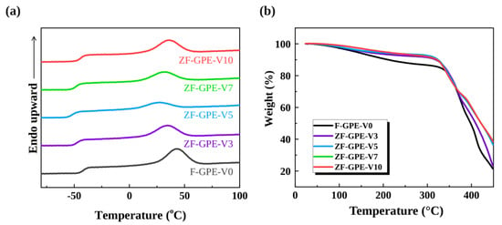
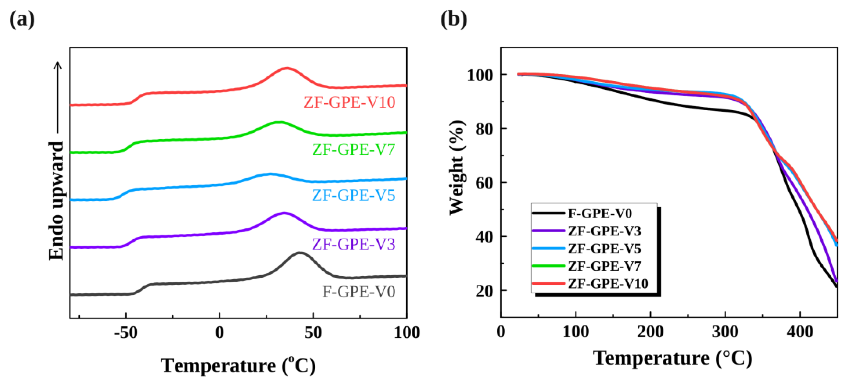
Figure 2a shows the DSC thermograms of F-GPE-V0 and the ZF-GPE series. Table 1 summarizes the low-temperature transition range and midpoint for each formulation. F-GPE-V0 exhibited a low-temperature baseline transition with a midpoint of −41.7 °C. The transition midpoint shifted to −47.3 and −51.8 °C for ZF-GPE-V3 and ZF-GPE-V5, respectively. ZF-GPE-V5 thus had the lowest transition midpoint of the electrolytes tested. As the VIPS content increased further, the midpoint shifted to −48.4 °C for ZF-GPE-V7 and −44.1 °C for ZF-GPE-V10. The low-temperature baseline steps are consistent with a glass transition of the solvated polymer phase, with all five transition midpoints lying below 25 °C. A separate broad endotherm was observed between approximately 27 and 43 °C (Figure 2a). Regarding the endothermic peak in a range of 27–50 °C, there is a possibility of melting transitions in a similar temperature range for PEGDA-based electrolytes containing an ionic liquid and a silver salt [46]. Melting of locally ordered domains may therefore contribute to the broad endotherm observed in the present gels.
Figure 2.
Thermal properties of the gel polymer electrolytes with different VIPS contents. (a) DSC curves of F-GPE-V0, ZF-GPE-V3, ZF-GPE-V5, ZF-GPE-V7 and ZF-GPE-V10. (b) TGA curves of the corresponding gel polymer electrolytes.
Table 1.
Thermal-transition parameters obtained from the DSC curves.
Figure 2b shows how the mass of each GPE changed with temperature during TGA. F-GPE-V0 exhibits a gradual mass decrease before entering its principal decomposition stage, whereas the incorporation of VIPS delays both the initial and intermediate mass losses. The temperature at 10% mass loss (T10%) is 238 °C for F-GPE-V0, while the corresponding T10% for ZF-GPE-V5 is 266 °C. This corresponds to an increase of 28 °C. A similar increase was observed at 50% mass loss (T50%). T50% increases from 314 °C for F-GPE-V0 to 335 °C following the incorporation of 5 wt.% VIPS, representing an increase of 21 °C. Because evaporation of the liquid electrolyte contributes to mass loss below 300 °C, the higher T10% of ZF-GPE-V5 is consistent with greater solvent retention during heating. Consequently, the addition of VIPS most clearly improves mass retention before the main decomposition stage and enhances the thermal stability of the electrolyte.
3.3. Electrochemical Characterization
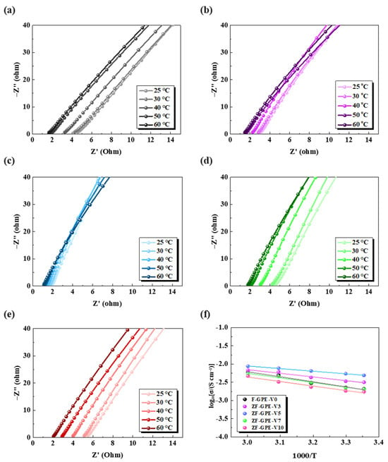
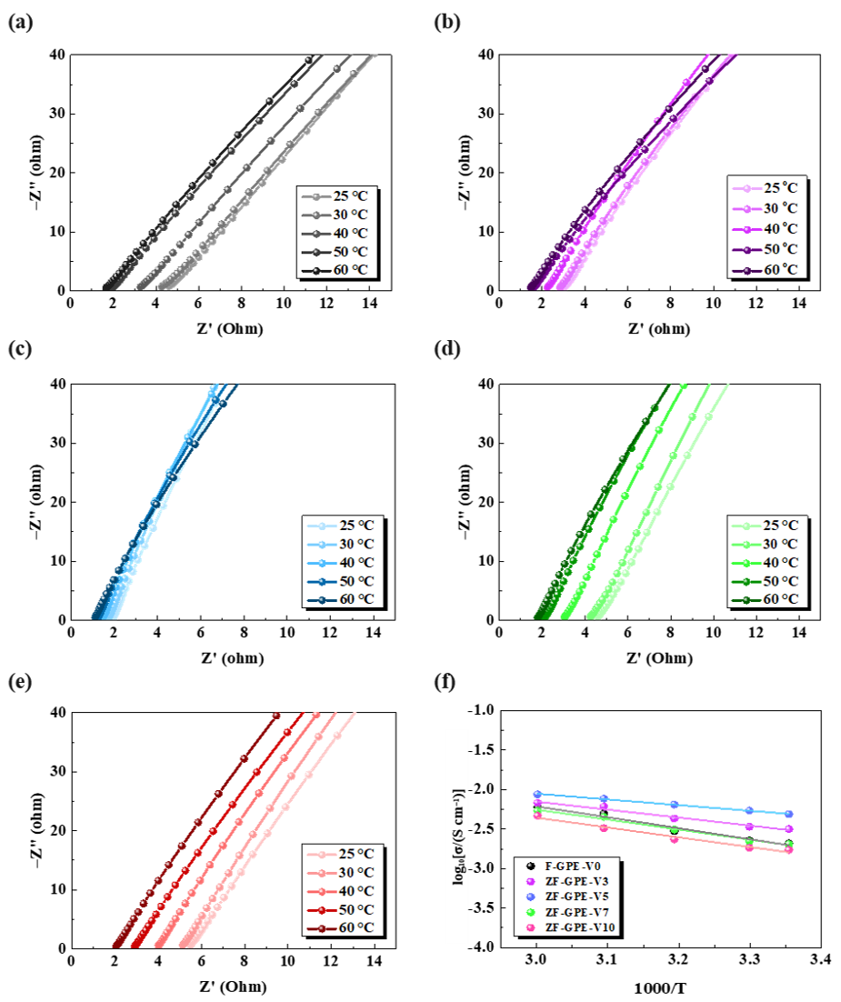
Temperature-dependent EIS measurements were conducted to determine how the VIPS content influences ionic transport in the GPEs and to identify the composition with the highest conductivity over the investigated temperature range. Figure 3a–e shows the Nyquist plots of F-GPE-V0 and the ZF-GPE series measured from 25 to 60 °C. The ionic conductivity increases continuously with temperature for all samples, indicating thermally activated ion transport. At 25 °C, the values for F-GPE-V0, ZF-GPE-V3, ZF-GPE-V5, ZF-GPE-V7 and ZF-GPE-V10 were 2.10, 3.17, 4.88, 2.05 and 1.72 mS cm−1, respectively. The ionic conductivity of ZF-GPE-V5 is 2.32 times higher than that of VIPS-free GPE. This enhancement in the room-temperature was maintained at 60 °C, where ZF-GPE-V5 reached 8.73 mS cm−1 and F-GPE-V0 reached 6.01 mS cm−1. Table 2 summarizes the ionic conductivities calculated from the corresponding bulk resistances. These results suggest that addition of VIPS helps Li+ ion transport more freely in the polymer network. At higher VIPS contents, however, stronger ionic associations and the possible formation of locally rigid zwitterion-rich domains may restrict polymer segmental motion and reduce overall ionic mobility. Among the five compositions, ZF-GPE-V5 gave the highest tabulated conductivity at every temperature tested. The decrease at 7 and 10 wt.% could be attributed to the conductivity gain depended on the amount of VIPS added to the PEGDA/TFEMA host.
Figure 3.
Nyquist plots from 25 to 60 °C for (a) F-GPE-V0, (b) ZF-GPE-V3, (c) ZF-GPE-V5, (d) ZF-GPE-V7 and (e) ZF-GPE-V10. (f) Arrhenius plots of the effective ionic conductivity.
Table 2.
Calculated ionic conductivity of the GF/A supported gel electrolytes (mS cm−1).
Figure 3f shows the Arrhenius plots for the five GPE formulations. For each formulation, log(σ) varies linearly with 1000/T over the measured range of 25–60 °C. This linear behavior indicates that ionic conduction followed an Arrhenius-type thermally activated process and suggests that no pronounced change in the dominant transport regime occurred within this temperature range. Table 3 lists the activation energy (Ea) calculated for each GPE using the Arrhenius equation. F-GPE-V0 had an activation energy of 26.59 kJ mol−1. The incorporation of 3 wt.% VIPS decreased this value to 19.57 kJ mol−1, and ZF-GPE-V5 had the lowest value, 13.87 kJ mol−1. The relatively shallow slope of ZF-GPE-V5 therefore indicates the most favorable ion-transport kinetics among the prepared electrolytes. By contrast, increasing the VIPS content beyond 5 wt.% raised Ea to 24.31 kJ mol−1 for ZF-GPE-V7, and 23.66 kJ mol−1 for ZF-GPE-V10. Both values exceeded that of ZF-GPE-V5, although Ea decreased slightly from ZF-GPE-V7 to ZF-GPE-V10. The higher activation energies at higher VIPS contents may reflect stronger ionic associations and reduced polymer segmental mobility [17].
Table 3.
Activation energies for ionic conduction in the F-GPE-V0 and ZF-GPE gel polymer electrolytes obtained from Arrhenius fitting.
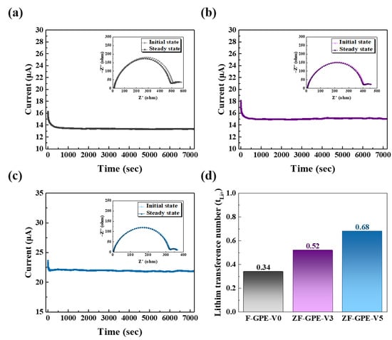
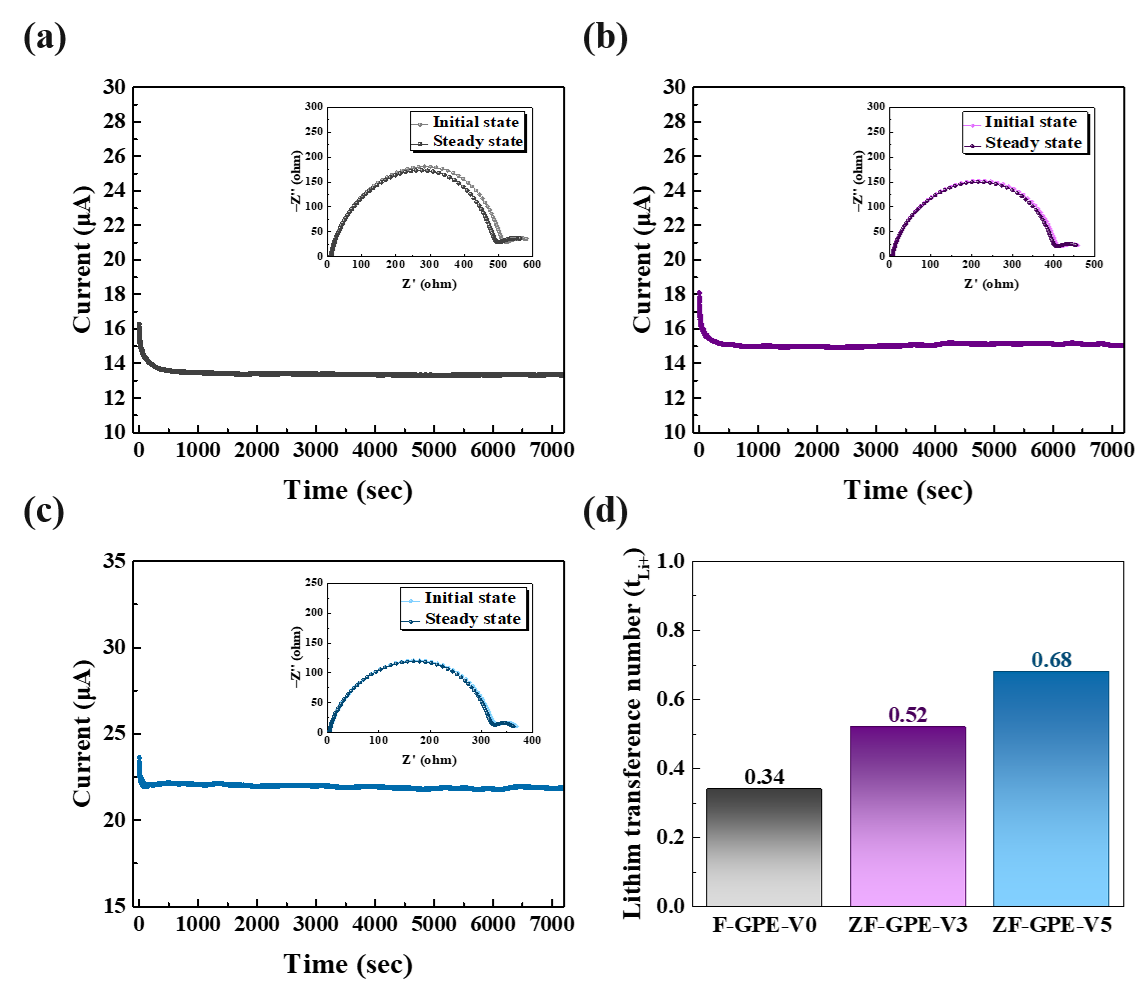
Figure 4 shows the current responses of Li symmetric cells containing F-GPE-V0, ZF-GPE-V3, and ZF-GPE-V5, respectively, during DC polarization at 25 °C. Following application of a 9.5 mV bias, the current in each cell decreased rapidly and then varied more slowly over the remainder of the 7200 s measurement. The initial current (I0) was sampled at 0.5 s, and the terminal current (Iss) was averaged over 6600–7200 s. As summarized in Table 4, the current decreased from 16.27 to 13.34 µA for F-GPE-V0 and from 18.09 to 15.12 µA for ZF-GPE-V3, corresponding to decreases of 18% and 16%, respectively. ZF-GPE-V5 had the highest initial current, 23.63 µA, and retained a terminal current of 21.86 µA, corresponding to the smallest relative decrease in the three cells (7.5%). The impedance spectra recorded before and after polarization are shown in the insets of Figure 4a–c. Before polarization, the interfacial resistance (R0) decreased across the series from 506.10 Ω for F-GPE-V0 to 405.38 Ω for ZF-GPE-V3 and 323.67 Ω for ZF-GPE-V5. The same ordering was observed after polarization, with Rss values of 483.89, 398.77, and 319.28 Ω, respectively. Thus, the lower interfacial resistance of ZF-GPE-V5 was already evident before the DC bias was applied and persisted throughout the comparison. These interfacial resistances were evaluated separately from the high-frequency bulk resistance used to calculate ionic conductivity in Figure 3. Using the measured bias, the initial and terminal currents, and the corresponding interfacial resistances in the Bruce–Vincent equation [42,43,44,45] gave apparent Li+ transference numbers of 0.34, 0.52, and 0.68 for F-GPE-V0, ZF-GPE-V3, and ZF-GPE-V5, respectively (Figure 4d). The increase across these three formulations indicates that the Li+ transport behavior under the same polarization protocol varied with VIPS loading. Interactions between the zwitterionic groups and electrolyte ions may contribute to this trend [27,28,29,30,31,32].
Figure 4.
Current transients and impedance spectra before and after polarization at 25 °C for (a) F-GPE-V0, (b) ZF-GPE-V3 and (c) ZF-GPE-V5. (d) Apparent Li+ transference numbers obtained from the Bruce–Vincent equation.
Table 4.
Currents and interfacial resistances of Li|GPE|Li cells at 25 °C before and after polarization under 9.5 mV bias.
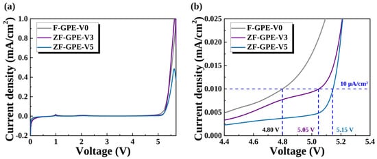
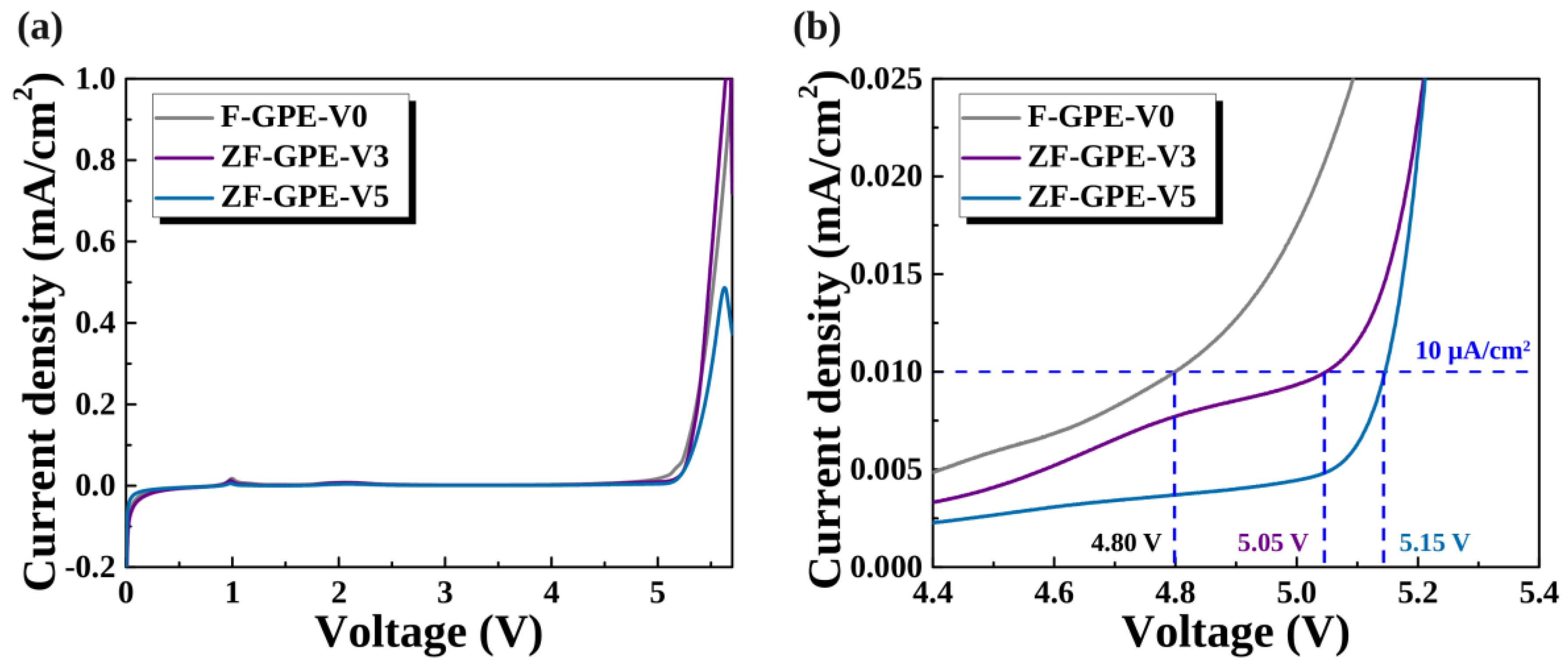
Figure 5a compares the oxidative stability ofF-GPE-V0, ZF-GPE-V3, and ZF-GPE-V5, as evaluated by LSV using SS|GPE|Li cells at 25 °C. At 25 °C, the oxidation current density reached 10 µA cm−2 at 4.80, 5.05 and 5.15 V (vs. Li/Li+) for F-GPE-V0, ZF-GPE-V3 and ZF-GPE-V5, respectively (Figure 5b). ZF-GPE-V5 therefore shows a 0.35 V positive shift in oxidation onset and a lower oxidation current in this potential range. Under identical measurement conditions, these observations indicate that VIPS incorporation delays the kinetic onset of electrolyte oxidation at the electrode. Because both F-GPE-V0 and ZF-GPE-V5 contain TFEMA, the positive shift in oxidation onset cannot be attributed solely to the fluorinated component. Instead, the comparison suggests that VIPS incorporation into the PEGDA/TFEMA network modifies the local ionic and interfacial environment, thereby delaying the onset of electrolyte oxidation. Such interactions may reduce the availability of oxidation-prone species and suppress parasitic oxidative reactions at elevated potentials.
Figure 5.
Linear sweep voltammetry of F-GPE-V0, ZF-GPE-V3 and ZF-GPE-V5 on stainless steel at 25 °C and 1 mV s−1. (a) Full sweeps. (b) Enlarged oxidation region. The horizontal dashed line marks the 10 µA cm−2 criterion.
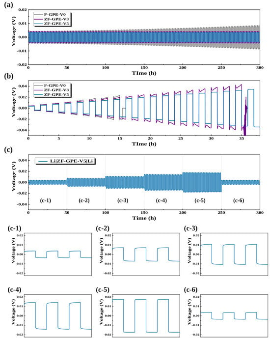
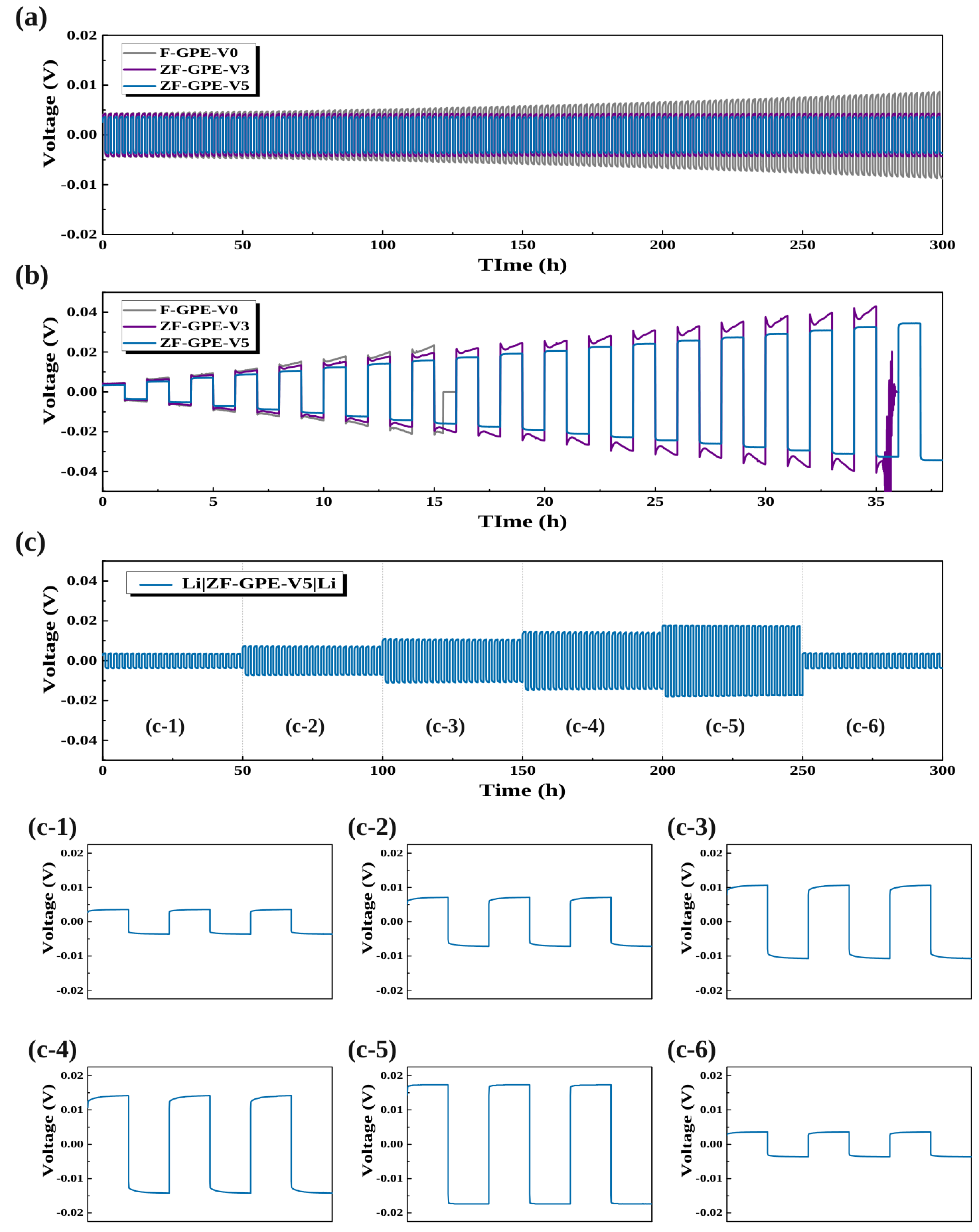
Figure 6 compares lithium plating and stripping profiles for F-GPE-V0, ZF-GPE-V3, and ZF-GPE-V5. In Figure 6a, polarization was quantified as the mean absolute cell voltage over complete plating and stripping cycles at 0.10 mA cm−2. For F-GPE-V0, the mean polarization increased from 4.34 mV during the first 50 h to 7.81 mV during the final 50 h, an increase ratio of 79.95%. Over the same intervals, the polarization of ZF-GPE-V3 changed only slightly, from 4.08 to 4.13 mV, while that of ZF-GPE-V5 remained close to 3.5 mV. The separation between the F-GPE-V0 and ZF-GPE-V5 profiles therefore became more pronounced over the 300 h, primarily because the voltage required to sustain the prescribed current increased progressively in the F-GPE-V0 profile. Furthermore, the Li symmetric cell containing ZF-GPE-V5 operated stably for 1000 h at 0.1 mA cm−2 (Figure S2). Figure 6b illustrates the response of critical current density (CCD) test. The current density was increased from 0.1 to 1.0 mA cm−2 in increments of 0.05 mA cm−2, with one complete plating and stripping cycle per step. F-GPE-V0 completed the 0.40 mA cm−2 step before its voltage collapsed toward zero during the 0.45 mA cm−2 step. ZF-GPE-V3 completed the 0.90 mA cm−2 step and exhibited pronounced voltage fluctuations during the subsequent 0.95 mA cm−2 step before collapse. The ZF-GPE-V5 profile retained alternating positive and negative voltages through 1.00 mA cm−2, the upper limit of the experiment. Figure 6c examines the current dependence of polarization for ZF-GPE-V5. The sequence comprises six 50 h intervals at 0.1, 0.2, 0.3, 0.4, 0.5, and again 0.1 mA cm−2. For the final three cycles at each increasing current step, shown in Figure 6(c-1–c-5), the mean absolute voltages were 3.45, 6.90, 10.36, 13.81, and 17.28 mV, respectively. During the segment, the cell maintains areal capacity of 0.5 mAh cm−2 per half-cycle at 0.5 mA cm−2 current density. Over its final three cycles, the positive and negative branches averaged +17.20 and −17.35 mV, respectively, giving a branch separation of 34.55 mV. At the return step of 0.10 mA cm−2 (Figure 6(c-6)), the mean absolute voltage was 3.51 mV, within 0.06 mV of the initial low-current value. The profiles suggest that ZF-GPE-V5 sustain lower polarization than F-GPE-V0 during repeated lithium plating and stripping.
Figure 6.
Lithium plating and stripping at 25 °C. (a) Voltage profiles over 300 h at 0.1 mA cm−2 for F-GPE-V0, ZF-GPE-V3 and ZF-GPE-V5. (b) Stepped-current profiles, with one cycle at each current density. (c) Response of ZF-GPE-V5 during successive 50 h steps at 0.1, 0.2, 0.3, 0.4 and 0.5 mA cm−2 and on returning to 0.1 mA cm−2. Panels (c-1–c-6) show the final three cycles of each step.
3.4. Galvanostatic Cycling and Rate Capability Performance
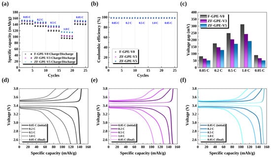
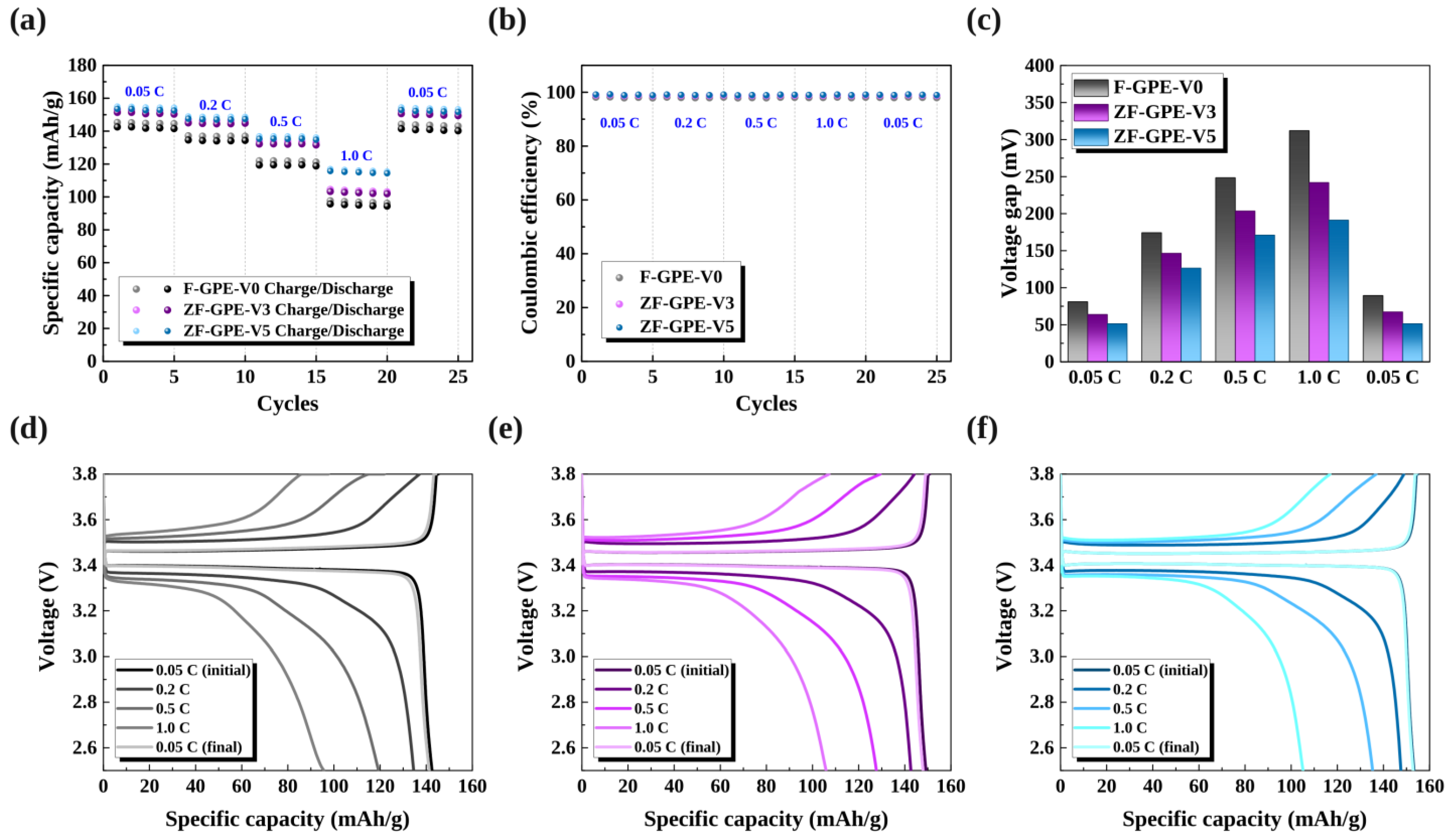
Figure 7a compares the rate capability of LFP|Li cells containing F-GPE-V0, ZF-GPE-V3, and ZF-GPE-V5 at 25 °C. Each cell was cycled five times at each rate between 2.5 and 3.8 V. At the initial rate of 0.05 C, the mean specific discharge capacities were 142.00, 150.80, and 153.00 mAh g−1 for F-GPE-V0, ZF-GPE-V3, and ZF-GPE-V5, respectively. ZF-GPE-V3 and ZF-GPE-V5 showed similar discharge capacities at 0.2 C (144.62 and 147.22 mAh g−1, respectively) and 0.5 C (132.02 and 135.22 mAh g−1, respectively). The difference between these two electrolytes became more pronounced at 1.0 C. At this rate, the discharge capacities were 94.95, 102.49, and 114.95 mAh g−1 for F-GPE-V0, ZF-GPE-V3, and ZF-GPE-V5, corresponding to 66.86%, 67.97%, and 75.13% of their respective initial capacities at 0.05 C. When the rate returned to 0.05 C, the discharge capacities recovered to 140.73, 149.93, and 152.23 mAh g−1 for F-GPE-V0, ZF-GPE-V3, and ZF-GPE-V5, respectively. All three cells thus recovered more than 99% of their initial low-rate capacity. The clearest difference among the electrolytes was the capacity accessible at 1.0 C, where ZF-GPE-V5 delivered 20.00 mAh g−1 more than F-GPE-V0 and 12.45 mAh g−1 more than ZF-GPE-V3. Furthermore, ZF-GPE-V5 exhibits the highest Coulombic efficiencies over all each charge/discharge raets, As shown in Figure 7b. The mean Coulombic efficiencies over the 25-cycle rate sequence were 98.02%, 98.82%, and 99.02% for F-GPE-V0, ZF-GPE-V3, and ZF-GPE-V5, respectively. Figure 7c compares the voltage gap between charge and discharge, evaluated at the midpoint of the respective charge and discharge capacities. The corresponding voltage profiles in Figure 7d–f show the characteristic plateaus of the LiFePO4/FePO4 redox couple [47, 48]. As the C-rate increased, the charge plateau shifted to higher voltages and the discharge plateau shifted to lower voltages. At 1.0 C, the voltage gap was 0.31 V for F-GPE-V0, 0.24 V for ZF-GPE-V3, and 0.19 V for ZF-GPE-V5. The smaller gap for ZF-GPE-V5 is consistent with lower cell polarization, allowing more capacity to be delivered before the lower cutoff voltage was reached. For ZF-GPE-V5, the voltage gap returned to its initial value of 0.052 V when the rate was reduced to 0.05 C. The recovery of both the voltage gap and the discharge capacity indicates that the capacity decrease at higher rates was largely reversible over this rate sequence.
Figure 7.
LFP|GPE|Li rate comparison at 25 °C. (a) Charge and discharge capacities, (b) Coulombic efficiency and (c) charge–discharge voltage gap. Voltage profiles are shown for (d) F-GPE-V0, (e) ZF-GPE-V3 and (f) ZF-GPE-V5 at the initial 0.05 C, 0.2 C, 0.5 C, 1.0 C and final 0.05 C steps.
3.5. Raman Spectra
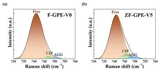
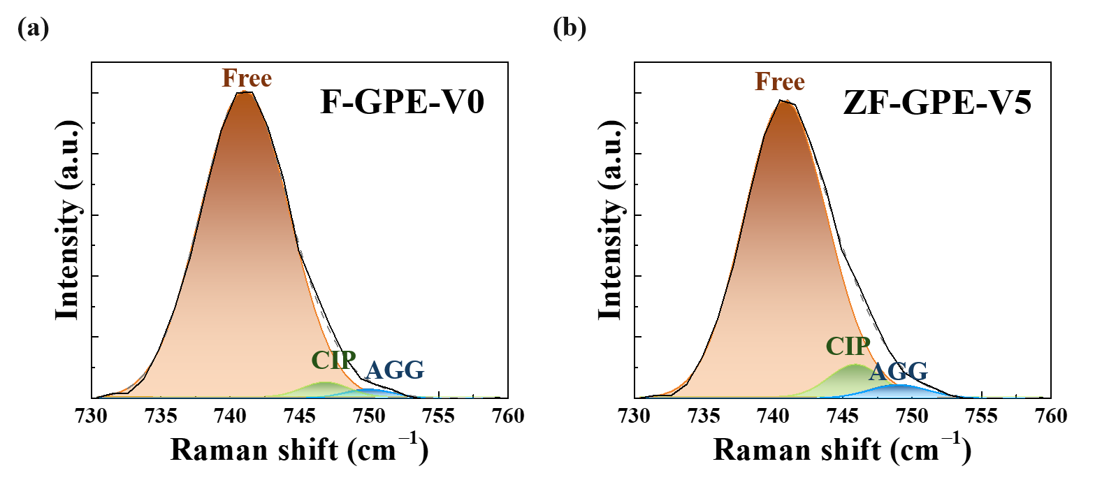
Figure 8a,b depict the Raman spectra of F-GPE-V0 and ZF-GPE-V5. Both F-GPE-V0 and ZF-GPE-V5 exhibit a dominant Raman component near 741 cm−1, assigned to free TFSI−. This component accounts for 96.04% of the total fitted area in F-GPE-V0 and 90.76% in ZF-GPE-V5 (Table 5). With the addition of 5 wt.% VIPS, the relative area of the component assigned to contact ion pairs (CIPs) increases from 2.46% to 6.38%, while that of the component assigned to aggregates (AGGs) increases from 1.50% to 2.86%. Together, these higher-wavenumber components account for 3.96% of the fitted area in F-GPE-V0 and 9.24% in ZF-GPE-V5. Raman bands near 746–750 cm−1 have been associated with more strongly coordinated TFSI− environments in LiTFSI electrolytes [49]. The increased contribution of these bands therefore suggests that VIPS alters the local coordination environment of TFSI−, possibly through electrostatic interactions involving the zwitterionic groups [16,17,29]. The change in anion coordination is accompanied by an increase in the Li+ transference number from 0.34 for F-GPE-V0 to 0.68 for ZF-GPE-V5. The LFP cell containing ZF-GPE-V5 also exhibits lower polarization at 1.0 C, with a charge–discharge voltage gap of 0.19 V compared with 0.31 V for F-GPE-V0. Taken together, the Raman and electrochemical results suggest that the change in the local TFSI− environment may be one factor contributing to the greater relative contribution of Li+ to ionic transport in ZF-GPE-V5. This difference in transport behavior may, in turn, help explain the lower polarization observed at 1.0 C.
Figure 8.
Normalized Raman spectra of (a) F-GPE-V0 and (b) ZF-GPE-V5 in the TFSI− coordination region. The colored peaks show the three fitted components in order of increasing Raman shift (P1, P2 and P3). Their positions and relative areas are listed in Table 5.
Table 5.
Fitted Raman positions and relative areas of the three TFSI− components.
3.6. Long-Term Cycling of the LFP Cell
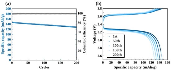
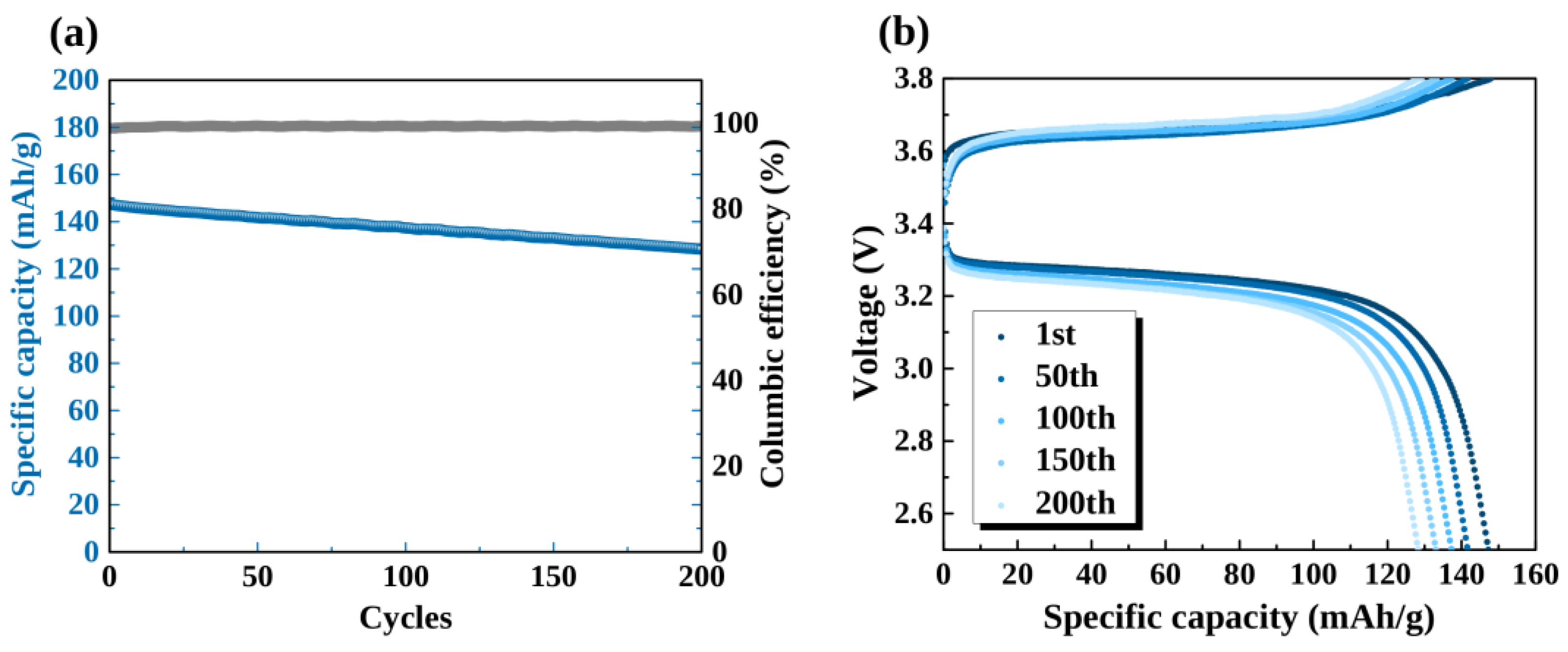
Figure 9a shows the cycling performance of the LFP|ZF-GPE-V5|Li cell over 200 cycles at 0.2 C and 25 °C. The specific discharge capacity decreased from 147.21 mAh g−1 in the first cycle to 128.31 mAh g−1 at the 200th cycle, corresponding to a capacity retention of 87.16%. The capacity decreased gradually without an abrupt collapse, and the average Coulombic efficiency was 99.23%, with values consistently close to 100% throughout cycling. These results demonstrate sustained cell operation over 200 cycles, although the gradual capacity loss indicates cumulative degradation during cycling. Figure 9b compares the charge–discharge profiles for the 1st, 50th, 100th, 150th, and 200th cycles. The characteristic LFP charge and discharge plateaus were preserved throughout cycling, consistent with continued Li+ insertion and extraction through the Fe2+/Fe3+ redox reaction. The progressive reduction in capacity was accompanied by a slight increase in the separation between the charge and discharge curves, indicating increased cell polarization. This increase may reflect changes in interfacial resistance, electrode–electrolyte contact, or ion-transport limitations. The voltage profiles alone cannot distinguish among these contributions.
Figure 9.
Long-term cycling of LFP|ZF-GPE-V5|Li at 0.2 C and 25 °C. (a) Specific discharge capacity and Coulombic efficiency. (b) Voltage profiles at selected cycles through cycle 200.
Consequently, the rate-capability and cycling results indicate that ZF-GPE-V5 provides sufficient ionic transport and electrochemical stability for LFP|Li cell operation at room temperature. The relatively high capacities maintained at elevated C-rates, the nearly complete capacity recovery upon returning to 0.05 C, the stable Coulombic efficiency, and the gradual capacity decay over 200 cycles are consistent with the favorable ion-transport properties of ZF-GPE-V5 observed in the preceding electrochemical characterization. The cross-linked PEGDA-based network may help maintain the dimensional integrity of the electrolyte, while interactions between the zwitterionic groups of VIPS and ionic species may facilitate Li+ transport and thereby contribute to the improved electrochemical response. However, the cell data alone cannot directly establish changes in SEI composition or lithium-deposition morphology, or identify specific mechanisms of interfacial stabilization. Additional post-mortem morphological and spectroscopic analyses would be required to verify these effects. Future work should also include cycling tests using high-nickel NCM cathodes to evaluate the high-voltage performance of ZF-GPE-V5.
4. Conclusions
In this study, we prepared a fluorinated GPE for room-temperature lithium-metal batteries by in situ thermal copolymerization of PEGDA, TFEMA, and the zwitterionic monomer VIPS. Systematic variation in the VIPS content revealed a non-monotonic dependence of the electrolyte properties on composition, with ZF-GPE-V5 exhibiting the most favorable overall electrochemical performance among the investigated formulations. Thermal analysis showed that the temperature corresponding to 10% mass loss (T10%) increased from 238 to 266 °C, demonstrating improved resistance to thermally induced solvent loss after incorporation of 5 wt.% VIPS. Furthermore, ZF-GPE-V5 achieved an ionic conductivity of 4.88 mS cm−1 at 25 °C, compared with 2.10 mS cm−1 for the VIPS-free F-GPE-V0. The tLi+ also increased from 0.34 to 0.68, indicating a greater relative contribution of Li+ to ionic transport following VIPS incorporation. In addition, the oxidation onset shifted to a higher potential from 4.80 to 5.15 V (vs. Li/Li+). The enhanced ion-transport properties of ZF-GPE-V5 were accompanied by stable electrochemical operation in lithium-metal cells. The Li|ZF-GPE-V5|Li symmetric cell maintained regular lithium plating and stripping behavior for 300 h at 0.1 mA cm−2, without the progressive polarization increase and voltage collapse observed for the VIPS-free electrolyte. Also, it operated stably for 1000 h despite exhibiting large polarization. Moreover, the polarization increased reversibly as the applied current density was raised to 0.5 mA cm−2 and recovered when the current density returned to 0.1 mA cm−2, indicating stable operation over the investigated current-density range. The LFP|ZF-GPE-V5|Li cells delivered an initial discharge capacity of 153.00 mAh g−1 at 0.05 C and maintained 114.95 mAh g−1 at 1.0 C. When the rate returned to 0.05 C, the discharge capacity recovered to 152.23 mAh g−1, corresponding to 99.50% of its initial value. During long-term cycling at 0.2 C, the cell retained 87.16% of its initial discharge capacity after 200 cycles, with an average Coulombic efficiency of 99.23%.
Overall, these results demonstrate that incorporating an appropriate amount of zwitterionic VIPS into a fluorinated PEGDA/TFEMA gel polymer network can simultaneously enhance room-temperature ionic transport, increase the relative contribution of Li+ to ionic conduction, improve resistance to oxidative and thermally induced degradation and support stable lithium-metal and LFP cell operation. The ZF-GPE-V5 formulation therefore provides a promising basis for designing multifunctional GPEs for room-temperature lithium-metal batteries. Further investigation using post-cycling morphological and spectroscopic characterization, together with testing against higher-voltage cathodes, will be necessary to clarify the underlying interfacial stabilization mechanisms and evaluate the broader applicability of this electrolyte design.
Supplementary Materials
The following supporting information can be downloaded at https://www.mdpi.com/article/10.3390/polym18222844/s1: Figure S1 shows the VIPS NMR site assignments. Figure S2 compares long-term lithium plating and stripping with F-GPE-V0 and ZF-GPE-V5. Table S1 gives the monomer feed, calculated dry polymer mass and gel fraction for each formulation.
Author Contributions
G.H.: conceptualization, data curation, investigation, methodology, validation, visualization, writing—review and editing. S.K. (Suyeon Kim): conceptualization, investigation, visualization, writing—original draft. S.L.: formal analysis, investigation. D.Y.: investigation, validation. S.K. (Sooncheol Kwon): project administration, supervision. J.J.: conceptualization, funding acquisition, project administration, supervision, writing—review and editing. All authors have read and agreed to the published version of the manuscript.
Funding
This work was supported by the Korea Institute of Energy Technology Evaluation and Planning (KETEP) and the Ministry of Climate, Energy & Environment (MCEE) of the Republic of Korea (No. 20224000000020). This work was also supported by the Ministry of Science and ICT (MSIT), Korea, under the ICT Challenge and Advanced Network of HRD (ICAN) support program (IITP-2026-RS-2024-00437186), supervised by the Institute for Information & Communications Technology Planning & Evaluation (IITP).
Data Availability Statement
The data are available from the corresponding author upon reasonable request.
Conflicts of Interest
The authors declare that they have no known competing financial interests or personal relationships that could have appeared to influence the work reported in this paper.
References
- Cheng, X.-B.; Zhang, R.; Zhao, C.-Z.; Zhang, Q. Toward safe lithium metal anode in rechargeable batteries: A review. Chem. Rev. 2017, 117, 10403–10473. [Google Scholar] [CrossRef] [Scilit] [PubMed]
- Lin, D.; Liu, Y.; Cui, Y. Reviving the lithium metal anode for high-energy batteries. Nat. Nanotechnol. 2017, 12, 194–206. [Google Scholar] [CrossRef] [Scilit] [PubMed]
- Xu, W.; Wang, J.; Ding, F.; Chen, X.; Nasybulin, E.; Zhang, Y.; Zhang, J.-G. Lithium metal anodes for rechargeable batteries. Energy Environ. Sci. 2014, 7, 513–537. [Google Scholar] [CrossRef] [Scilit]
- Tikekar, M.D.; Choudhury, S.; Tu, Z.; Archer, L.A. Design principles for electrolytes and interfaces for stable lithium-metal batteries. Nat. Energy 2016, 1, 16114. [Google Scholar] [CrossRef] [Scilit]
- Tarascon, J.-M.; Armand, M. Issues and challenges facing rechargeable lithium batteries. Nature 2001, 414, 359–367. [Google Scholar] [CrossRef] [Scilit] [PubMed]
- Monroe, C.; Newman, J. The impact of elastic deformation on deposition kinetics at lithium/polymer interfaces. J. Electrochem. Soc. 2005, 152, A396–A404. [Google Scholar] [CrossRef] [Scilit]
- Peled, E.; Menkin, S. Review—SEI: Past, present and future. J. Electrochem. Soc. 2017, 164, A1703–A1719. [Google Scholar] [CrossRef] [Scilit]
- Hallinan, D.T.; Balsara, N.P. Polymer electrolytes. Annu. Rev. Mater. Res. 2013, 43, 503–525. [Google Scholar] [CrossRef] [Scilit]
- Mindemark, J.; Lacey, M.J.; Bowden, T.; Brandell, D. Beyond PEO—Alternative host materials for Li+-conducting solid polymer electrolytes. Prog. Polym. Sci. 2018, 81, 114–143. [Google Scholar] [CrossRef] [Scilit]
- Stephan, A.M. Review on gel polymer electrolytes for lithium batteries. Eur. Polym. J. 2006, 42, 21–42. [Google Scholar] [CrossRef] [Scilit]
- Song, J.Y.; Wang, Y.Y.; Wan, C.C. Review of gel-type polymer electrolytes for lithium-ion batteries. J. Power Sources 1999, 77, 183–197. [Google Scholar] [CrossRef] [Scilit]
- Zhou, X.; Zhou, Y.; Yu, L.; Qi, L.; Oh, K.-S.; Hu, P.; Lee, S.-Y.; Chen, C. Gel polymer electrolytes for rechargeable batteries toward wide-temperature applications. Chem. Soc. Rev. 2024, 53, 5291–5337. [Google Scholar] [CrossRef] [Scilit] [PubMed]
- Baskoro, F.; Wong, H.Q.; Yen, H.-J. Strategic structural design of a gel polymer electrolyte toward a high efficiency lithium-ion battery. ACS Appl. Energy Mater. 2019, 2, 3937–3971. [Google Scholar] [CrossRef] [Scilit]
- Song, M.-K.; Cho, J.-Y.; Cho, B.W.; Rhee, H.-W. Characterization of UV-cured gel polymer electrolytes for rechargeable lithium batteries. J. Power Sources 2002, 110, 209–215. [Google Scholar] [CrossRef] [Scilit]
- Wang, Y.-J.; Kim, D. PEGDA/PVdF/F127 gel-type polymer electrolyte membranes for lithium secondary batteries. J. Power Sources 2007, 166, 202–210. [Google Scholar] [CrossRef] [Scilit]
- Lu, F.; Gao, X.; Wu, A.; Sun, N.; Shi, L.; Zheng, L. Lithium-containing zwitterionic poly(ionic liquid)s as polymer electrolytes for lithium-ion batteries. J. Phys. Chem. C 2017, 121, 17756–17763. [Google Scholar] [CrossRef] [Scilit]
- Li, G.; Guan, X.; Wang, A.; Wang, C.; Luo, J. Cations and anions regulation through zwitterionic gel electrolytes for stable lithium metal anodes. Energy Storage Mater. 2020, 24, 574–578. [Google Scholar] [CrossRef] [Scilit]
- Chen, F.; Guo, C.; Zhou, H.; Shahzad, M.W.; Liu, T.X.; Oleksandr, S.; Sun, J.; Dai, S.; Xu, B.B. Supramolecular network structured gel polymer electrolyte with high ionic conductivity for lithium metal batteries. Small 2022, 18, 2106352. [Google Scholar] [CrossRef] [Scilit] [PubMed]
- Jiao, X.; Wang, J.; Gao, G.; Zhang, X.; Fu, C.; Wang, L.; Wang, Y.; Liu, T. Stable Li-metal batteries enabled by in situ gelation of an electrolyte and in-built fluorinated solid electrolyte interface. ACS Appl. Mater. Interfaces 2021, 13, 60054–60062. [Google Scholar] [CrossRef] [Scilit] [PubMed]
- He, H.; Wang, Y.; Li, M.; Qiu, J.; Wen, Y.; Chen, J. In situ cross-linked fluorinated gel polymer electrolyte based on PEGDA-enabled lithium-ion batteries with a wide temperature operating range. Chem. Eng. J. 2023, 467, 143311. [Google Scholar] [CrossRef] [Scilit]
- Liu, S.; Tian, W.; Shen, J.; Wang, Z.; Pan, H.; Kuang, X.; Yang, C.; Chen, S.; Han, X.; Quan, H.; et al. Bioinspired gel polymer electrolyte for wide temperature lithium metal battery. Nat. Commun. 2025, 16, 2474. [Google Scholar] [CrossRef] [Scilit] [PubMed]
- Doyle, M.; Fuller, T.F.; Newman, J. Modeling of galvanostatic charge and discharge of the lithium/polymer/insertion cell. J. Electrochem. Soc. 1993, 140, 1526–1533. [Google Scholar] [CrossRef] [Scilit]
- Valøen, L.O.; Reimers, J.N. Transport properties of LiPF6-based Li-ion battery electrolytes. J. Electrochem. Soc. 2005, 152, A882. [Google Scholar] [CrossRef] [Scilit]
- Pesko, D.M.; Timachova, K.; Bhattacharya, R.; Smith, M.C.; Villaluenga, I.; Newman, J.; Balsara, N.P. Negative transference numbers in poly(ethylene oxide)-based electrolytes. J. Electrochem. Soc. 2017, 164, E3569–E3575. [Google Scholar] [CrossRef] [Scilit]
- France-Lanord, A.; Grossman, J.C. Correlations from ion pairing and the Nernst-Einstein equation. Phys. Rev. Lett. 2019, 122, 136001. [Google Scholar] [CrossRef] [Scilit] [PubMed]
- Chazalviel, J.-N. Electrochemical aspects of the generation of ramified metallic electrodeposits. Phys. Rev. A 1990, 42, 7355–7367. [Google Scholar] [CrossRef] [Scilit] [PubMed]
- Yu, Y.; Lu, F.; Sun, N.; Wu, A.; Pan, W.; Zheng, L. Single lithium-ion polymer electrolytes based on poly(ionic liquid)s for lithium-ion batteries. Soft Matter 2018, 14, 6313–6319. [Google Scholar] [CrossRef] [Scilit]
- Jones, S.D.; Nguyen, H.; Richardson, P.M.; Chen, Y.-Q.; Wyckoff, K.E.; Hawker, C.J.; Clément, R.J.; Fredrickson, G.H.; Segalman, R.A. Design of polymeric zwitterionic solid electrolytes with superionic lithium transport. ACS Cent. Sci. 2022, 8, 169–175. [Google Scholar] [CrossRef] [Scilit] [PubMed]
- Chen, W.; Hai, F.; Gao, X.; Guo, J.; Yi, Y.; Xue, W.; Tang, W.; Li, M. In situ polymerized zwitterionic copolymer ionic gel electrolytes with high performance for lithium-ion batteries. ACS Appl. Mater. Interfaces 2024, 16, 36696–36704. [Google Scholar] [CrossRef] [Scilit] [PubMed]
- Liu, Y.; Hou, L.; Jiao, Y.; Wu, P. Decoupling of mechanical strength and ionic conductivity in zwitterionic elastomer gel electrolyte toward safe batteries. ACS Appl. Mater. Interfaces 2021, 13, 13319–13327. [Google Scholar] [CrossRef] [Scilit] [PubMed]
- Liu, S.; Cheng, H.; Mao, R.; Jiang, W.; Wang, L.; Song, Z.; Pei, M.; Zhang, T.; Hu, F. Designing Zwitterionic Gel Polymer Electrolytes with Dual-Ion Solvation Regulation Enabling Stable Sodium Ion Capacitor. Adv. Energy Mater. 2023, 13, 2300068. [Google Scholar] [CrossRef] [Scilit]
- Zheng, L.; Sundaram, H.S.; Wei, Z.; Li, C.; Yuan, Z. Applications of zwitterionic polymers. React. Funct. Polym. 2017, 118, 51–61. [Google Scholar] [CrossRef] [Scilit]
- Cha, J.; Nam, K.; Baek, J.; Seo, S.; Kwak, K.; Kim, J.-W.; Kim, W.; Ryu, K.H.; Kim, D.-W.; Kwon, E. Improving the oxidative stability of gel polymer electrolytes for lithium metal batteries. J. Mater. Chem. A 2023, 11, 14180–14186. [Google Scholar] [CrossRef] [Scilit]
- Wang, F.; Zhong, J.; Guo, Y.; Han, Q.; Liu, H.; Du, J.; Tian, J.; Tang, S.; Cao, Y. Fluorinated nonflammable in situ gel polymer electrolyte for high-voltage lithium metal batteries. ACS Appl. Mater. Interfaces 2023, 15, 39265–39275. [Google Scholar] [CrossRef] [Scilit] [PubMed]
- Lin, Y.; Shen, Z.; Huang, J.; Zhu, J.; Jiang, S.; Zhan, S.; Xie, Y.; Chen, J.; Shi, Z. In situ construction of fluorine-containing modified gel polymer electrolyte with high interfacial stability for high-rate lithium metal battery. J. Power Sources 2023, 584, 233612. [Google Scholar] [CrossRef] [Scilit]
- Song, M.-K.; Rhee, H.-W. Ultraviolet-cured polyethylene glycol diacrylate/polyvinylidene fluoride blend gel polymer electrolytes. Electrochem. Solid-State Lett. 2001, 4, A105–A107. [Google Scholar] [CrossRef] [Scilit]
- Lin, Y.; Chen, J.; Zhu, J.; Zhong, J.; Yang, K.; Deng, H.; Huang, J.; Shen, Z.; Shi, Z. In situ construction of tetraethylene glycol diacrylate-based gel polymer electrolyte for long-lifespan lithium metal batteries. Surf. Interfaces 2023, 37, 102737. [Google Scholar] [CrossRef] [Scilit]
- Chen, B.; Wang, M.; Wang, X.; Zhao, Q.; Wang, Y.; Gao, G. Poly(ionic liquid)s with superior swelling and enrichment properties in solvents. Polym. Chem. 2021, 12, 2731–2742. [Google Scholar] [CrossRef] [Scilit]
- Berthier, C.; Gorecki, W.; Minier, M.; Armand, M.B.; Chabagno, J.M.; Rigaud, P. Microscopic investigation of ionic conductivity in alkali metal salts-poly(ethylene oxide) adducts. Solid State Ion. 1983, 11, 91–95. [Google Scholar] [CrossRef] [Scilit]
- Li, Z.; Fu, J.; Zhou, X.; Gui, S.; Wei, L.; Yang, H.; Li, H.; Guo, X. Ionic conduction in polymer-based solid electrolytes. Adv. Sci. 2023, 10, 2201718. [Google Scholar] [CrossRef] [Scilit] [PubMed]
- Méry, A.; Rousselot, S.; Lepage, D.; Dollé, M. A critical review for an accurate electrochemical stability window measurement of solid polymer and composite electrolytes. Materials 2021, 14, 3840. [Google Scholar] [CrossRef] [Scilit] [PubMed]
- Evans, J.; Vincent, C.A.; Bruce, P.G. Electrochemical measurement of transference numbers in polymer electrolytes. Polymer 1987, 28, 2324–2328. [Google Scholar] [CrossRef] [Scilit]
- Bruce, P.G.; Vincent, C.A. Steady-state current flow in solid binary electrolyte cells. J. Electroanal. Chem. Interfacial Electrochem. 1987, 225, 1–17. [Google Scholar] [CrossRef] [Scilit]
- Zugmann, S.; Fleischmann, M.; Amereller, M.; Gschwind, R.M.; Wiemhöfer, H.D.; Gores, H.J. Measurement of transference numbers for lithium-ion electrolytes via four different methods: A comparative study. Electrochim. Acta 2011, 56, 3926–3933. [Google Scholar] [CrossRef] [Scilit]
- Shao, Y.; Gudla, H.; Brandell, D.; Zhang, C. Transference number in polymer electrolytes: Mind the reference-frame gap. J. Am. Chem. Soc. 2022, 144, 7583–7587. [Google Scholar] [CrossRef] [Scilit] [PubMed]
- Chao, Z.; Radka, B.P.; Xu, K.; Crouch, G.M.; Han, D.; Go, D.B.; Bohn, P.W.; Fullerton-Shirey, S.K. Direct-write formation and dissolution of silver nanofilaments in ionic liquid–polymer electrolyte composites. Small 2018, 14, 1802023. [Google Scholar] [CrossRef] [Scilit] [PubMed]
- Padhi, A.K.; Nanjundaswamy, K.S.; Goodenough, J.B. Phospho-olivines as positive-electrode materials for rechargeable lithium batteries. J. Electrochem. Soc. 1997, 144, 1188–1194. [Google Scholar] [CrossRef] [Scilit]
- Yamada, A.; Koizumi, H.; Nishimura, S.-I.; Sonoyama, N.; Kanno, R.; Yonemura, M.; Nakamura, T.; Kobayashi, Y. Room-temperature miscibility gap in LixFePO4. Nat. Mater. 2006, 5, 357–360. [Google Scholar] [CrossRef] [Scilit] [PubMed]
- Touja, J.; Salembier Peyrovi, P.; Tison, Y.; Martinez, H.; Gimello, O.; Louvain, N.; Stievano, L.; Monconduit, L. Effects of the electrolyte concentration on the nature of the solid electrolyte interphase of a lithium metal electrode. Energy Technol. 2023, 11, 2201037. [Google Scholar] [CrossRef] [Scilit]

Disclaimer/Publisher’s Note: The statements, opinions and data contained in all publications are solely those of the individual author(s) and contributor(s) and not of MDPI and/or the editor(s). MDPI and/or the editor(s) disclaim responsibility for any injury to people or property resulting from any ideas, methods, instructions or products referred to in the content. |
© 2026 by the authors. Licensee MDPI, Basel, Switzerland. This article is an open access article distributed under the terms and conditions of the Creative Commons Attribution (CC BY) license.