


Highlights
What are the main findings?
- •
- Cross-scene transfer showed markedly different behavior for the two correction components, with range corrections demonstrating substantially higher stability than azimuth-time corrections.
- •
- Scene-specific correction established a robust meter-level accuracy baseline, significantly reducing the median planimetric RMSE from 57.50 to 1.53 m.
- •
- Transfer accuracy was associated with source–target acquisition compatibility, particularly satellite platform consistency, orbit direction (ascending/descending), and Doppler centroid frequency difference.
What are the implications of the main findings?
- •
- Calibration-derived correction parameters may support geometric correction of GF-3B/C target scenes without local GCPs, but the achieved accuracy depends on the transferred component and source–target compatibility.
- •
- Source scenes should be selected based on acquisition compatibility rather than mere geographic proximity. Range corrections showed potential for reuse within the tested acquisition conditions, whereas azimuth-time corrections require rigorous compatibility screening.
Abstract
Accurate geometric positioning is essential for the quantitative application of synthetic aperture radar (SAR) imagery. Although geometric calibration can effectively reduce systematic positioning errors, the cross-scene transferability of calibration-derived correction parameters remains insufficiently evaluated, particularly under different acquisition conditions. This study investigates the geometric positioning accuracy and parameter transferability of GF-3B/C SAR imagery using observations from the Xilinhot and Lijiang calibration sites. Scene-specific range and azimuth-time corrections were first estimated within the Range–Doppler framework, followed by cross-scene transfer experiments and acquisition-condition sensitivity analyses. The results indicate that scene-specific correction established a high-accuracy baseline, reducing the median planimetric root-mean-square error (RMSE) from 57.50 m to 1.53 m. In cross-scene transfer, the range correction exhibited substantially higher stability than the azimuth-time correction. Range-only transfer yielded a median combined two-dimensional RMSE of 50.98 m, whereas combined transfer yielded 60.51 m, compared with 57.85 m before transfer. Transfer performance was associated with source–target acquisition compatibility, yielding superior accuracy when satellite platform, orbit direction, and Doppler centroid frequency differences were well matched. Furthermore, cross-site transfer demonstrated accuracy comparable to that of same-site transfer under compatible conditions. These findings indicate that parameter transferability depends on both the specific correction component and acquisition compatibility. For GF-3B/C imagery in ground-control-point-free (GCP-free) scenarios, range corrections offer strong potential for direct reuse, whereas azimuth-time corrections require rigorous compatibility screening during source-scene selection.
1. Introduction
Synthetic aperture radar (SAR) is an active microwave remote sensing technique that can acquire surface information with limited dependence on illumination and weather conditions. It has been widely used in Earth observation [1], disaster monitoring [2,3], and topographic mapping [4,5]. Many such applications demand precise georeferencing of image observations to their true geographic locations. However, the geometric positioning accuracy of SAR imagery can be affected by various error sources, including uncertainties in sensor state vectors, terrain representation, atmospheric signal propagation, and image processing workflows [6]. These errors introduce spatial offsets between estimated and actual ground target positions, thereby constraining applications that rely on high-precision geospatial data [7]. Rigorous geometric modeling and accuracy assessment are therefore essential for characterizing SAR system performance and ensuring the reliability of downstream high-accuracy applications [8].
Accurate geometric positioning of SAR imagery relies on a sensor model that establishes the spatial relationship between image coordinates and ground coordinates. Geometric processing for SAR can be implemented using either rigorous physical models or empirical mathematical models. Representative rigorous physical models include the Range–Doppler (R-D) model [9], the Leberl model [10], and the Konecny model [1]. Among them, the R-D model is most widely adopted for spaceborne SAR imagery, as it explicitly formulates the imaging geometry via slant-range and Doppler constraints coupled with satellite orbit state vectors. However, employing a rigorous geometric model alone does not guarantee error-free positioning. Radar timing errors introduce systematic offsets in the measured slant range and azimuth time [11]. Orbit-related uncertainties degrade the reconstructed target position because satellite state vectors are direct inputs to the geometric model [12]. Errors in the Doppler parameter may further introduce azimuth positioning deviations, particularly when the Doppler centroid frequency is not accurately modeled. In addition, terrain elevation errors propagate into horizontal positioning errors owing to the inherent side-looking imaging geometry, whereas atmospheric propagation delays impair radar signal travel time, thereby introducing additional range offsets [13]. Collectively, these error sources comprise both relatively stable, system-related components and acquisition-dependent variations, ultimately leading to scene-to-scene discrepancies in residual positioning errors.
To compensate for the aforementioned systematic errors, external calibration incorporating high-precision ground reference points is routinely conducted to correct the overall geometric bias of the sensor model [11,14]. However, conventional geometric correction methods rely heavily on the availability of ground control points (GCPs) within the target image footprint [15,16]. This operational dependency makes it difficult to achieve rapid, high-precision geometric processing in vast control-free regions (e.g., remote mountainous or overseas areas) or emergency response scenarios. To circumvent this constraint, reusing geometric correction parameters derived from calibrated source scenes for uncalibrated target scenes offers a practical and efficient solution [6]. Yang et al. used DEM-based simulated-image matching to estimate geometric correction parameters from one reference GF-3 image and applied them to one same-orbit image and one cross-orbit image [17]. Their results demonstrated the feasibility of cross-scene parameter reuse in these two cases. A systematic assessment across a larger set of source–target pairs, including the separate and combined transfer behavior of the range and azimuth-time corrections and their associations with acquisition conditions, remained to be conducted.
To address these issues, this study systematically evaluates the geometric positioning accuracy and parameter transferability of GF-3B/C spaceborne SAR imagery using multi-temporal observations from the Xilinhot and Lijiang calibration sites. First, scene-specific geometric corrections are executed within the Range–Doppler framework to establish a high-accuracy positioning baseline for subsequent transfer evaluation. Next, the calibration-derived parameters are transferred across diverse scenes to quantify their cross-scene performance and elucidate the governing factors driving accuracy variations. Finally, this study integrates these empirical findings to evaluate parameter stability and provide empirical guidance for source-scene selection in ground-control-point-free (GCP-free) scenarios.
The remainder of this paper is organized as follows. Section 2 describes the calibration sites and experimental data. Section 3 presents the geometric correction and cross-scene transfer assessment methods. Section 4 reports the experimental results and performance evaluations. Section 5 discusses the governing factors and operational implications, and Section 6 draws the final conclusions.
2. Study Area and Data
2.1. Ground Calibration Sites
Supported by the Common Application Support Platform for Space Infrastructure Planning project, the Aerospace Information Research Institute, the Chinese Academy of Sciences (AIRCAS), has established a dual-site “South–North” SAR satellite calibration and validation (Cal/Val) network in Xilinhot and Lijiang. Each site is equipped with 4 active radar calibrators (ARCs), 10 automatic corner reflectors (CRs), and dozens of deployable CRs [18]. These facilities enable synergistic and remotely controlled operations across sites [19]. This integrated network provides a multisite collaborative Cal/Val capability for SAR satellites operating in L-, S-, and C-bands, accommodating spatial resolutions ranging from 1 to 20 m, and across various orbital inclinations. It is designed to satisfy the routine operational Cal/Val demands for SAR satellites in high-, medium-, and low-Earth orbits.
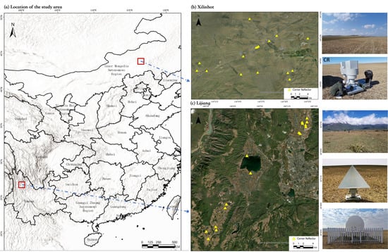
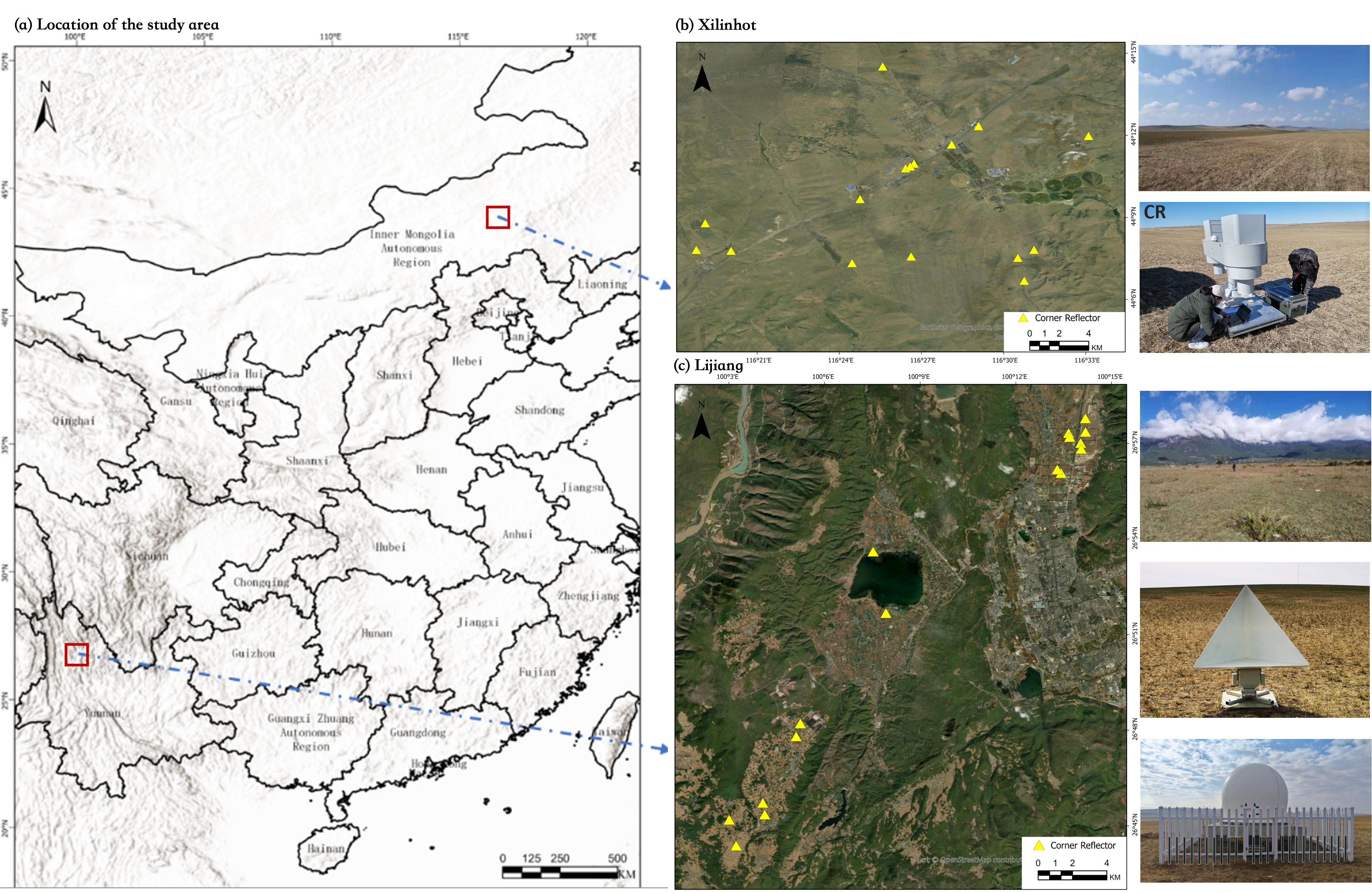
As shown in Figure 1, the Xilinhot and Lijiang calibration sites represent markedly different topographical settings. Xilinhot is characterized mainly by open grassland and relatively gentle relief [20], whereas Lijiang exhibits more complex mountainous terrain [21,22]. This geographic diversity provides an ideal experimental basis for evaluating model performance across diverse geometric conditions and background environments. By leveraging these sites, we systematically conducted in-orbit validation tasks for China’s GF-3 satellite series, including radiometric calibration, geometric positioning accuracy evaluation [23], and multimodal image quality assessment [24].
Figure 1.
Geographic locations of the calibration sites. (Yellow triangles indicate the locations of corner reflectors (CRs)).
2.2. Experimental Data
All data used in this experiment were acquired by the GF-3 satellite series, critical components of China’s High-Resolution Earth Observation System [25]. Operating at C-band with multi-polarization capability, the GF-3 satellite series offers high spatial resolution, wide coverage, diverse imaging modes, and long-term time-series monitoring capabilities [26]. GF-3 was launched in August 2016, and GF-3B and GF-3C were launched in November 2021 and April 2022, respectively, effectively supporting national applications, such as maritime monitoring, disaster risk assessment, and land resource investigation. This experiment utilized the images collected by GF-3B and GF-3C. To comprehensively evaluate geometric positioning accuracy across representative acquisition conditions, five imaging modes were included: Ultra-Fine Stripmap (UFS), Fine Stripmap I/II (FSI/FSII), and Quad-Polarization Stripmap I/II (QPSI/QPSII). The specific image parameters (resolution, swath width, and polarization) are listed in Table 1.
Table 1.
Parameters of the five typical imaging modes for GF-3 series satellites.
This experiment utilized 24 scenes of GF-3 series satellite imagery across two study areas, Lijiang and Xilinhot, covering five imaging modes: UFS, FSI, FSII, QPSI, and QPSII. During satellite overpasses, synchronous ground-truth experiments were conducted using corner reflectors. Therefore, each image contains a certain number of trihedral CRs that can be used as GCPs. Automated CRs with precisely adjustable azimuth and elevation angles were deployed onsite to maximize the radar backscatter signal and ensure high-precision imagery identification. This allows their main lobes to be pointed directly at the satellite’s signal path during overpass. The precise 3D geographic coordinates of these CRs were collected in the field using Real-Time Kinematic (RTK) technology, ensuring centimeter-level positioning accuracy. Before parameter estimation, potentially inconsistent CR observations were screened separately in the range and azimuth components. An observation was excluded only when, in either component, its absolute modified Z-score exceeded 3.5 and its absolute deviation exceeded 2 m. The spatial distribution of CRs across the two calibration sites is shown in Figure 1b,c, while Table 2 lists the detailed image parameters, acquisition conditions, and number of CR observations used in each scene.
Table 2.
Detailed parameters of the GF-3 satellite imagery used in the experiments.
3. Methods
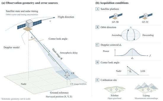
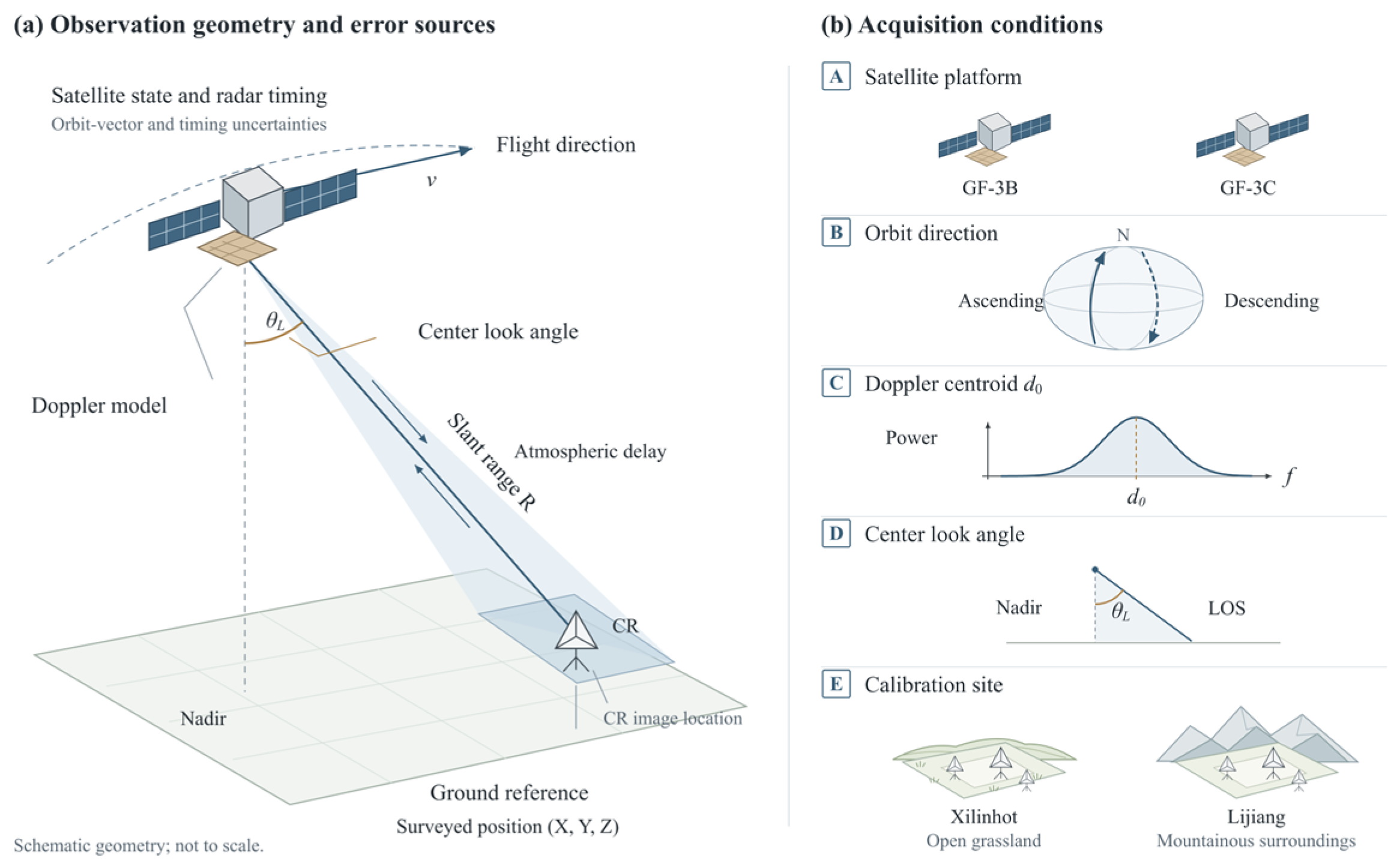
Figure 2 summarizes the SAR observation geometry, major potential sources of positioning error, and the acquisition conditions considered in the transfer analysis. Satellite state and radar timing uncertainties, atmospheric propagation delays, and Doppler modeling errors can affect the modeled image position [11,12,13]. Accuracy assessment also depends on the surveyed three-dimensional CR coordinates, including height, and the measured CR image locations. In this study, uncertainties in these reference observations are controlled through RTK surveying and precise CR image localization. Because atmospheric propagation delay was not independently computed in this experiment, its unmodeled range contribution was absorbed into the estimated range correction, while the range and azimuth-time corrections jointly compensated for the aggregate scene-specific geometric biases within the R-D framework without separately estimating the contribution of each physical error source. The intra-scene experiments evaluate the accuracy achieved by these corrections and describe residual variations across satellite platforms, imaging modes, orbit directions, and calibration sites. The applicability of the estimated correction parameters to other acquisitions is then assessed through cross-scene parameter transfer. Imaging mode is held fixed, while satellite platform, orbit direction, calibration site, Doppler centroid differences, and center look-angle consistency are examined to assess how source–target acquisition conditions are associated with transfer accuracy.
Figure 2.
SAR observation geometry and acquisition conditions considered in the transfer analysis.
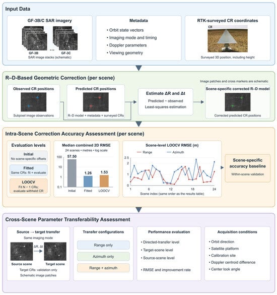
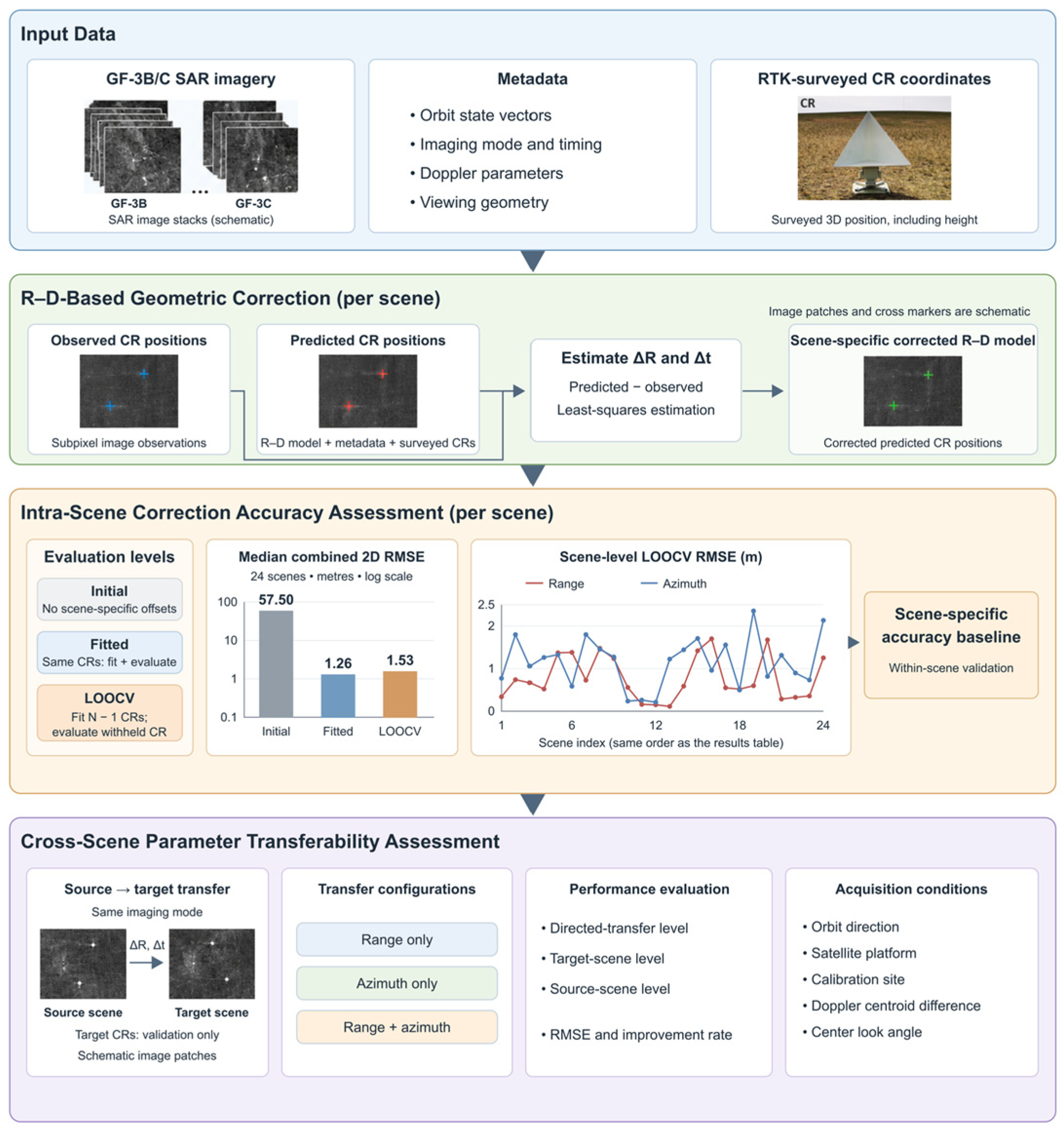
The overall workflow is shown in Figure 3. First, range and azimuth-time correction parameters are estimated for each scene within the R-D framework. Initial, fitted, and leave-one-out cross-validation (LOOCV) accuracies are then compared to establish a scene-specific accuracy baseline, followed by the residual comparisons described above. Next, the estimated parameters are transferred between scenes using range-only, azimuth-only, and combined corrections. Transfer accuracy is evaluated relative to the uncorrected target-scene accuracy, and matched comparisons are used to examine its associations with source–target acquisition conditions. Target-scene reference observations are used only for accuracy evaluation, not for estimating or refining the transferred parameters.
Figure 3.
Overall workflow of the proposed method, including R-D-based geometric correction, intra-scene accuracy evaluation, and cross-scene parameter transferability analysis.
3.1. R-D Model-Based Geometric Correction
The geometric correction was performed within the rigorous Range–Doppler (R-D) framework [27], which establishes the spatial relationship between ground coordinates and SAR image coordinates using the slant-range constraint, Doppler geometry, satellite orbit vectors, and the surveyed three-dimensional coordinates of the reference targets. Given the ground coordinates of a target, its theoretical image position can be derived by solving the R-D equations using the metadata accompanying the SAR product.
In practice, residual systematic errors inevitably remain because the input parameters of the R-D model are not error-free [28]. In this study, atmospheric propagation delay was not calculated separately and therefore remained part of the aggregate range bias represented by . Scene-specific geometric biases were represented by corrections to the range start slant distance and the azimuth start time [29], expressed as
where and are the nominal range start slant distance and azimuth start time extracted from the SAR metadata, respectively; and and are the range and azimuth-time correction parameters to be estimated. The two parameters represent the aggregate range- and azimuth-related geometric biases of each acquisition, rather than parameterizing individual physical error sources.
For each CR, the theoretical image coordinates were calculated from its surveyed ground coordinates using the corrected R-D model. The corresponding observed image coordinates were determined at subpixel precision from the SAR image. The relationship between the theoretical coordinates and the correction parameters can be written as
where and are the theoretical line and sample coordinates of the -th CR, denotes its known ground position, and represents the satellite state vectors and imaging parameters embedded in the R-D model. The residual vector for each CR is defined as the difference between the theoretically derived and directly observed image coordinates:
The scene-specific correction parameters were estimated using a least-squares optimization that minimizes the sum of squared residuals over all retained CR observations:
The estimated and were subsequently used to construct the corrected R-D model for each scene. These correction parameters were estimated independently for individual acquisitions without assuming cross-scene invariance. Their scene-specific correction accuracy and cross-scene transferability are evaluated in the following sections.
3.2. Intra-Scene Correction Accuracy Assessment
Prior to evaluating the cross-scene transferability of the correction parameters, the intrinsic correction capability of each individual scene was first evaluated using its self-contained ground reference information. This intra-scene assessment serves two purposes: first, to establish a scene-specific accuracy baseline for the subsequent transferability experiments; second, to characterize the residual positioning errors remaining after scene-specific correction. Accordingly, the evaluation includes scene-specific accuracy assessment and analysis of residual error characteristics.
3.2.1. Scene-Specific Accuracy Evaluation
Geometric positioning accuracy was evaluated in the range and azimuth directions, as well as by their combined two-dimensional (2D) planimetric error. For each reference target, the range and azimuth residuals were first converted into metric units using the corresponding ground pixel spacings. For a set of reference observations, the range and azimuth root mean square errors (RMSEs) were calculated as
where and denote the range and azimuth residuals, in meters, of the -th reference target, respectively. The planimetric RMSE was calculated by combining the two image-coordinate components:
In this study, denotes the integrated two-dimensional planimetric error derived from the range and azimuth components in the SAR image-coordinate system. The identical evaluation metrics were consistently applied in the subsequent cross-scene transferability assessment.
For each SAR scene, positioning accuracy was evaluated at three distinct levels to explicitly differentiate the original uncorrected positioning error, the internal fitting capability of the correction model, and its independent correction accuracy. These three levels are denoted as , , and , respectively, where represents the range, azimuth, or combined two-dimensional planimetric component.
was calculated using the nominal R-D model without scene-specific correction and represents the inherent geometric positioning error of the SAR image. was obtained after estimating and from all available reference targets within the scene and subsequently evaluating the post-fit residuals at the same target locations. It therefore reflects how well the adopted two-parameter correction model fits the systematic geometric offsets within the scene. However, because the same observations are used for both parameter estimation and accuracy calculation, the fitted residuals represent the internal consistency of the model rather than an independent measure of correction accuracy.
To evaluate the independent correction accuracy, leave-one-reference-point-out cross-validation (LOOCV) scheme was performed for each SAR scene [30,31]. For a scene containing available reference targets, one target was withheld as the validation point in each iteration, while the remaining targets were used to estimate the scene-specific correction parameters and . The estimated parameters were then applied to the corrected R-D model, and the positioning residual of the withheld target was calculated independently. This process was repeated times until each reference target served once as the validation point. The predicted residuals from all iterations were then combined to calculate . Compared with , which is calculated from the training points, provides an internal cross-validated estimate of scene-specific correction accuracy and was therefore used as the baseline for subsequent cross-scene transferability assessment.
3.2.2. Analysis of Residual Error Characteristics
After the scene-specific correction accuracy was established by LOOCV, the remaining positioning errors were compared across categorical acquisition conditions to describe variations in residual correction accuracy. Each of the 24 SAR scenes yielded a single , which was used as the scene-level metric for residual geometric error.
Four categorical factors were considered: satellite platform, imaging mode, orbit direction, and calibration site. These factors account for variations in platform stability, imaging configuration, orbit geometry, and site-related conditions, respectively. The statistical distributions and median values across these respective groups were compared to characterize variations in residual correction accuracy.
3.3. Cross-Scene Parameter Transferability Assessment
The intra-scene assessment in Section 3.2 establishes the correction accuracy achievable using local reference observations, but does not establish whether the estimated parameters remain applicable to other acquisitions. Building on this baseline, the correction parameters estimated from a given SAR scene were further transferred to other scenes to evaluate their cross-scene transferability. This experimental design allows a direct comparison between the positioning accuracy obtained after parameter transfer and the scene-specific correction performance obtained when target-scene ground reference information is available. Accordingly, the assessment was structured around two key dimensions: the positioning accuracy achieved through parameter transfer and the sensitivity of transfer accuracy to varying source–target acquisition conditions.
3.3.1. Parameter Transfer and Accuracy Evaluation
For each SAR scene, the scene-specific range and azimuth-time correction parameters, and , were first estimated using the procedure described in Section 3.1. In the cross-scene transfer experiment, the correction parameters derived from a source scene were directly integrated into the R-D model of a target scene, without re-estimation using the target scene’s ground reference observations. For a parameter transfer from source scene to target scene , the corrected range start slant distance and azimuth start time of the target scene were expressed as
where and are the correction parameters estimated from source scene , while and retain the intrinsic imaging geometry of target scene . The ground reference targets in the target scene were used exclusively for independent accuracy evaluation and did not participate in the estimation or refinement of the transferred parameters.
To reduce differences associated with imaging mode, the primary transfer experiments were conducted between scenes acquired in the same imaging mode. Imaging mode was therefore used as a pairing constraint, whereas Section 3.2.2 compared residual correction accuracy across modes. Under this pairing constraint, the single QPSII scene had no eligible same-mode counterpart and was therefore not included in the cross-scene transfer experiment. The remaining 23 scenes formed 62 unique scene pairs. Because parameter transfer is directional, each unique scene pair contributed two directed transfers, with the two scenes alternately serving as the source and target. The 62 scene pairs therefore resulted in 124 directed transfer experiments. To distinguish the transfer behavior of the two correction components, three transfer configurations were evaluated: range-only transfer , azimuth-only transfer , and combined transfer .
Transfer accuracy was evaluated using the range, azimuth, and 2D planimetric RMSE metrics defined in Section 3.2.1. For each target scene, the positioning RMSE obtained after parameter transfer was compared with its initial uncorrected positioning error. The relative change in positioning accuracy was quantified by the improvement rate
where the superscript tr denotes the post-transfer RMSE and d denotes the range (R), azimuth (A), or combined two-dimensional (P) component defined in Section 3.2.1. A positive improvement rate indicates reduced RMSE relative to the initial positioning baseline, whereas a negative value indicates degradation.
To account for the unequal numbers of eligible transfer pairs across scenes, transfer performance was evaluated at three aggregation levels. First, all 124 directed source–target transfers were treated as individual tests to characterize the overall distribution of pairwise transfer results. Second, for each target scene, the median result across all incoming transfers was calculated, after which the median across the 23 target scenes was used to obtain a target-scene-level summary. Third, an identical aggregation procedure was applied to outgoing transfers for each source scene to generate a source-scene-level summary. The RMSE and improvement rate were summarized consistently at all three levels. This multi-tier design mitigates bias arising from unequal scene representation and allows a comprehensive evaluation from pairwise, target-scene, and source-scene perspectives.
3.3.2. Analysis of Factors Associated with Transfer Accuracy
Building on the overall transfer evaluation in Section 3.3.1, the relationships between parameter-transfer accuracy and source–target acquisition conditions were systematically examined. This analysis aims to identify key operational conditions that can guide the selection of a suitable calibrated source scene when ground reference information is unavailable for the target scene. Within the same-mode transfer experiments, five factors were evaluated: orbit direction, satellite platform, calibration site, Doppler centroid frequency (), and center look angle [32]. These factors were selected to compare acquisition conditions potentially relevant to parameter reuse. Satellite platform and orbit direction distinguish platform-related characteristics and observation configurations; calibration site represents the spatial context of the acquisitions; and Doppler centroid differences and center look-angle consistency characterize aspects of source–target imaging-state and viewing-geometry compatibility [33]. These comparisons examine associations with transfer accuracy rather than the contributions of individual physical error sources. Here, denotes the constant term of the Doppler centroid frequency model provided in the image metadata.
The factor analysis was based on the combined 2D parameter transfer of the range and azimuth correction parameters. To examine associations with individual acquisition factors, a matched-comparison approach was implemented: one factor was evaluated at a time while the other major conditions were kept the same whenever permitted by the available data. Only matched scene groups containing both comparative states were retained for statistical comparison. The specific matching criteria used across the five factors are summarized in Table 3.
Table 3.
Matching criteria used to evaluate the impact of orbit direction, satellite platform, calibration site, Doppler centroid (), and center look angle parameter compatibility.
For orbit direction, transfers between scenes sharing the same orbit direction were compared against those with opposite directions, while keeping the satellite platform, imaging mode, and calibration site unchanged. Satellite-platform effects were examined by comparing within-platform and cross-platform transfers under identical imaging mode, calibration site, and orbit direction. Similarly, calibration-site effects were evaluated by comparing within-site and cross-site transfers after controlling for satellite platform, imaging mode, and orbit direction. Transfer performance in each comparison was characterized using the RMSE metrics defined in Section 3.2.1 and the improvement rate defined in Section 3.3.1.
Doppler centroid compatibility was quantified by the absolute difference between the source- and target-scene constant terms, and examined in two steps. First, the absolute difference in between the source and target scenes was related to the transfer improvement across all directed transfer tests using Spearman rank correlation. Second, a more strictly controlled comparison was conducted using a matched subset where satellite platform, imaging mode, calibration site, and orbit direction were identical. Within this matched subset, the source–target differences were partitioned at their median value to compare transfers with relatively smaller and larger Doppler offsets. The median value was used only to partition the available observations and was not treated as a general threshold for parameter transferability.
The center look angle was examined using the same matched subset by comparing transfers between scenes with identical and different recorded center look angles. Because the available dataset did not provide sufficient independent variation in center look angle and Doppler centroid differences, the observed relationships with transfer accuracy were interpreted as empirical associations rather than strictly independent causal effects.
Together, these matched comparisons characterize the associations between source–target acquisition conditions and parameter-transfer performance within the available dataset.
4. Results
4.1. Intra-Scene Correction Accuracy
This section evaluates the intra-scene geometric correction performance of the GF-3B/C SAR images. First, the scene-specific correction accuracy is assessed across three positioning accuracy tiers: the initial, fitted, and LOOCV results. The residual positioning errors are then analyzed to examine their behavior across diverse scenes and acquisition conditions.
4.1.1. Scene-Specific Correction Performance
Scene-specific correction performance was evaluated across the 24 quality-controlled GF-3B/C scenes using the initial, fitted, and LOOCV accuracy metrics defined in Section 3.2.1. Before correction, the planimetric RMSE ranged from 28.07 to 120.17 m, with a median of 57.50 m. After scene-specific correction, the median fitted RMSE decreased to 1.26 m, while the median LOOCV RMSE reached 1.53 m. Relative to the initial positioning baseline, the median LOOCV RMSE was reduced by 55.97 m, corresponding to a 97.3% reduction calculated from the two reported medians. All 24 scenes showed lower LOOCV RMSEs after correction, with values ranging from 0.26 to 2.47 m (Table 4). A sensitivity analysis excluding the four scenes with fewer than five retained CR observations (Scene IDs 338636, 807971, 807972, and 805657) yielded results consistent with those obtained from the full dataset.
Table 4.
Intra-scene geometric correction results for all 24 GF-3B/C scenes.
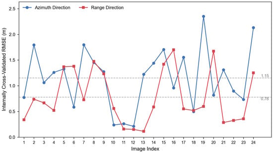
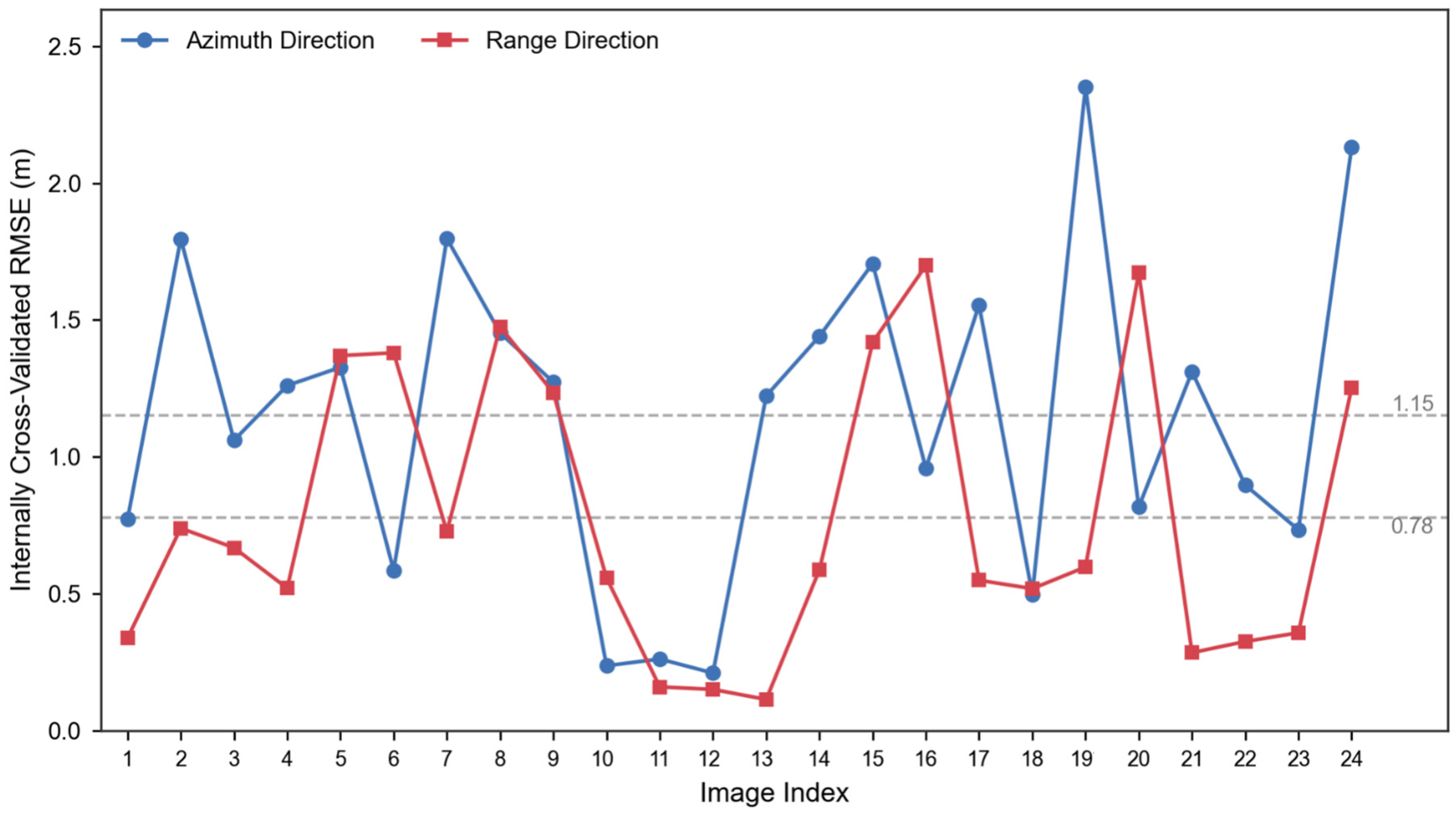
The residual errors also differed between the two image-coordinate directions. The mean LOOCV RMSE was 0.78 m in the range direction and 1.15 m in the azimuth direction, indicating a higher residual error in the azimuth direction. The scene-level range and azimuth accuracy distribution results are shown in Figure 4.
Figure 4.
Internally cross-validated range and azimuth RMSE for the 24 quality-controlled GF-3B/C scenes, ordered consistently with Table 4.
4.1.2. Residual Error Characteristics
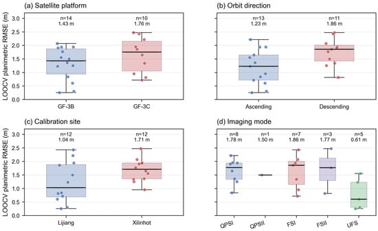
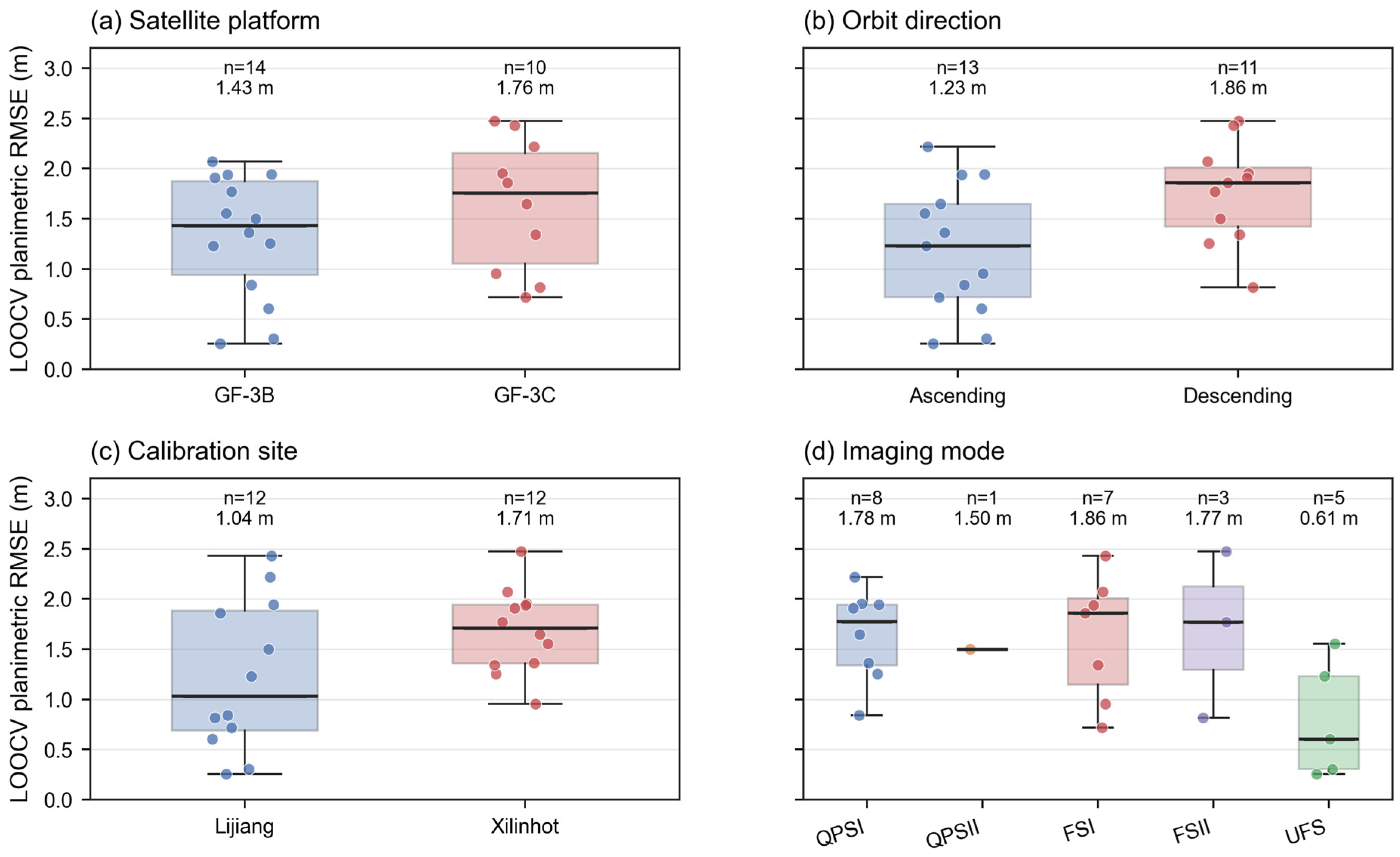
To evaluate residual errors after intra-scene correction, we compared error metrics across four scene-level conditions: satellite platform, orbit direction, calibration site, and imaging mode. Each of the 24 scenes contributed one , and the distributions and median values across the respective groups were compared (Figure 5).
Figure 5.
Distribution of scene-level LOOCV planimetric RMSEs across key acquisition conditions. Points represent individual scenes; boxes and horizontal bars depict the interquartile range and median for (a) satellite platform, (b) orbit direction, (c) calibration site, and (d) imaging mode.
The median LOOCV planimetric RMSE was 1.43 m for GF-3B and 1.76 m for GF-3C. By orbit direction, ascending scenes achieved a lower median RMSE than descending scenes (1.23 m vs. 1.86 m). Across calibration sites, Lijiang exhibited a lower median RMSE of 1.04 m compared to 1.71 m for Xilinhot. Among imaging modes represented by multiple scenes, the median RMSEs were 1.78 m for QPSI, 1.86 m for FSI, 1.77 m for FSII, and 0.61 m for UFS. The single QPSII scene yielded an RMSE of 1.50 m and was therefore plotted individually without a mode-level box.
Although the median residual errors varied across certain groups, their overall distributions showed considerable overlap, with scene-level LOOCV RMSEs consistently within the range of 0.26–2.47 m. Consequently, the residual positioning errors remained at the meter level across all evaluated satellite platforms, orbit directions, calibration sites, and imaging modes represented in the dataset.
4.2. Cross-Scene Parameter Transferability
4.2.1. Overall Transfer Accuracy
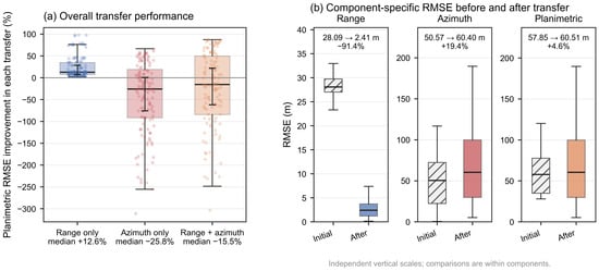
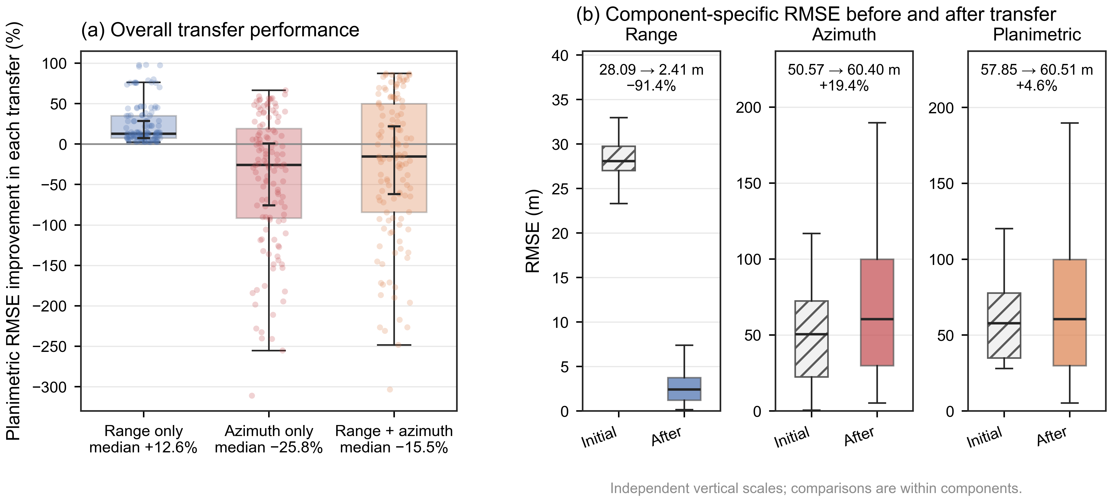
Based on the 124 directed same-mode transfer tests described in Section 3.3.1, transfer performance varied markedly across the three correction configurations (Table 5 and Figure 6; complete pairwise results are provided in Supplementary Table S1). Prior to correction, the median RMSE was 28.09 m in range, 50.57 m in azimuth, and 57.85 m in the image plane. Transferring only the range correction substantially reduced the median range RMSE from 28.09 to 2.41 m. All 124 tests demonstrated an improvement in planimetric RMSE, yielding a post-transfer median of 50.98 m and a median relative improvement of 12.6%. Conversely, transferring only the azimuth correction increased the median azimuth RMSE from 50.57 to 60.40 m. Only 45 of the 124 tests improved, whereas 79 tests (63.7%) showed degradation, with the relative change reaching −311.1% in the most severe case. The median performance deterioration was 25.8%. Transferring both corrections simultaneously increased the median planimetric RMSE from 57.85 to 60.51 m, with only 54 tests showing improvement and a median deterioration of 15.5%.
Table 5.
Same-mode transfer performance across 124 directed transfer tests derived from 62 scene pairs and 23 scenes.
Figure 6.
Overall same-mode cross-scene transfer accuracy. (a) Distribution of planimetric RMSE improvement across the 124 transfer tests for range-only, azimuth-only, and two-parameter transfer scheme (positive values indicate lower target-scene RMSE). (b) Comparison of range, azimuth, and planimetric RMSE before and after combined transfer.
The overall performance of the combined transfer depended strongly on the aggregation level. When pooling all 124 tests individually, the median relative change was −15.5% (median RMSE of 60.51 m). However, when taking the median across incoming transfers for each target scene and then across target scenes, the median change became +6.2% (median RMSE of 53.72 m). Applying the corresponding two-stage median aggregation to outgoing transfers per source scene yielded a median change of −13.3% (median RMSE of 53.67 m). Across all aggregation schemes, the range correction remained the more stable component. The sign reversal under target-scene-level aggregation indicates that the combined-transfer result was sensitive to the source–target pairing structure. In comparison, range-only transfer demonstrated consistently positive median improvements across all three aggregation schemes, with median improvements of approximately 12.6–12.8%.
4.2.2. Effects of Acquisition Conditions on Transfer Accuracy
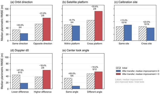
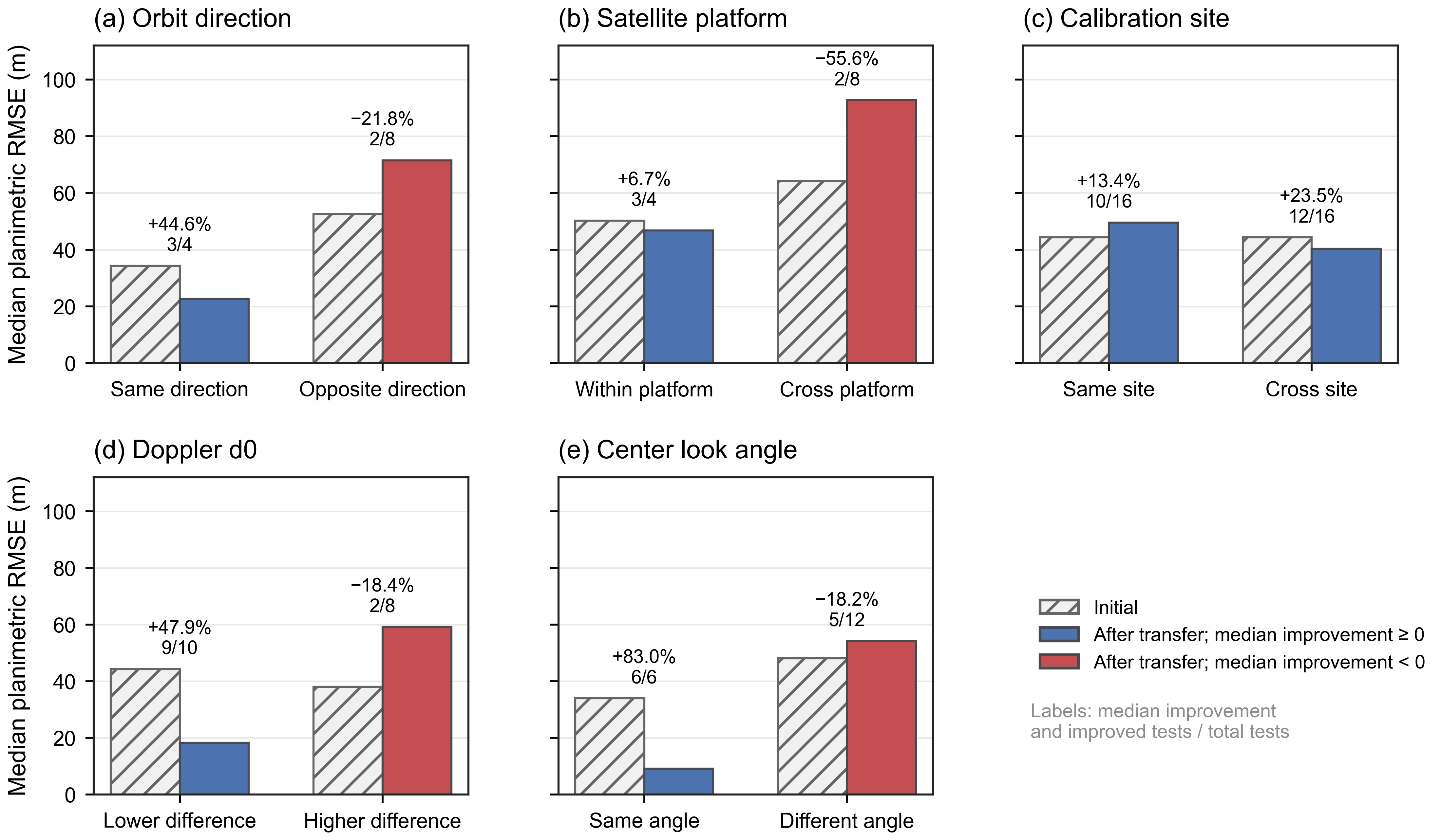
Section 4.2.1 revealed substantial variation in transfer performance across source–target scene pairs, particularly for the azimuth and combined corrections. This variation suggests that the compatibility of acquisition conditions between the source and target scenes is associated with transfer accuracy. To further examine this relationship, transfer results were evaluated under matched acquisition conditions across five key parameters: orbit direction, satellite platform, calibration site, Doppler centroid , and center look angle. Figure 7 summarizes these comparisons, while Table 6, Table 7, Table 8, Table 9 and Table 10 report the number of transfer tests, the median planimetric RMSE before and after transfer, the median and interquartile range (IQR; Q1–Q3) of the pairwise improvement rates, and the number of improved tests for each group. Together, these statistics provide a descriptive summary of the observed associations within the matched subsets.
Figure 7.
Two-parameter transfer accuracy under controlled acquisition conditions. Each panel compares the initial and post-transfer median planimetric RMSE for two groups defined by (a) orbit direction, (b) satellite platform, (c) calibration site, (d) Doppler difference, and (e) center look angle. Labels above the bars denote the median improvement percentage and the proportion of improved transfer tests.
Table 6.
Impact of orbit direction on two-parameter transfer accuracy.
Table 7.
Impact of satellite platform on two-parameter transfer accuracy.
Table 8.
Impact of calibration site on two-parameter transfer accuracy.
Table 9.
Impact of the Doppler difference on two-parameter transfer accuracy.
Table 10.
Impact of center look angle on two-parameter transfer accuracy.
For orbit direction, 12 matched transfer tests were retained (Figure 7a). Among the four tests with the same orbit direction, the median planimetric RMSE decreased from 34.24 to 22.61 m, yielding a median improvement of 44.6%, with three tests showing improvement. For the eight tests with opposite orbit directions, the median RMSE deteriorated from 52.59 to 71.48 m. The median decline was a 21.8% deterioration, and only two tests improved. The difference in median improvement between the two groups was approximately 66 percentage points. While the remaining range error was minor in both groups, the median azimuth error for opposite-direction transfers reached 71.40 m. For azimuth-only transfer, degradation occurred in two of the four same-direction tests and six of the eight opposite-direction tests. Scene 172799 provides a target-specific illustration of this pattern. Its initial azimuth RMSE was 116.90 m, and azimuth-only transfer degraded the target-scene accuracy for all three opposite-direction source scenes, whereas two of the three same-direction transfers improved it, further supporting the need for compatibility screening when transferring . Within this matched subset, same-direction transfers had a lower median post-transfer error. An azimuth-time error produces a displacement whose ground projection depends on the flight direction [32,34]. However, a change in orbit direction alone does not establish the cause of the observed degradation, because the target R-D model already uses the target orbit geometry. Furthermore, previous SAR calibration studies also show that azimuth positioning is sensitive to the alignment between radar and orbit time [29], with ascending and descending acquisitions operating under distinct viewing and propagation geometries.
For the satellite platform, 12 matched QPSI transfer tests were retained (Figure 7b). Among the four tests conducted on the same satellite platform, the median planimetric RMSE decreased from 50.20 to 46.78 m, yielding a median improvement of 6.7%, with three tests showing improvement. For the eight cross-platform tests between GF-3B and GF-3C, the median RMSE deteriorated from 64.19 to 92.72 m (a median decline of 55.6%), and only two tests improved. The median range error after cross-platform transfer was merely 4.00 m, whereas the median azimuth error was 92.62 m. These findings indicate that within this matched QPSI comparison, cross-platform transfer was less stable than within-platform transfer. Such a platform-dependent effect is physically reasonable because the range correction accounts for the instrument electronic delay, while the azimuth correction depends on synchronization between radar time and orbit time. Independent evaluations of Sentinel-1A and Sentinel-1B similarly estimated these timing offsets for each satellite and reported mode- or subswath-dependent azimuth offsets.
For calibration site, 32 matched transfer tests were analyzed (Figure 7c). Prior to transfer, both the same-site and cross-site groups exhibited an identical median initial planimetric RMSE of 44.29 m. After transfer, the median RMSEs shifted to 49.57 m for the same-site group and 40.27 m for the cross-site group. The median improvements calculated from the individual tests were 13.4% (10 of 16 tests improved) and 23.5% (12 of 16 tests improved), respectively. Within the matched comparisons available in this dataset, cross-site transfer between Xilinhot and Lijiang did not show lower accuracy than same-site transfer. Although the two calibration sites differ in their regional topographic settings, the corner reflectors used for validation were deployed in locally open and relatively flat areas. This localized environment likely mitigated terrain-induced discrepancies at the validation targets, thereby contributing to the comparable transfer performance observed between the two sites.
The effect of Doppler centroid was evaluated in two steps. First, all 124 transfer tests were used to determine the relation between the source–target Doppler centroid difference and the accuracy improvement achieved by transferring both corrections. The Spearman correlation was −0.773, indicating a negative association within the evaluated transfer dataset. Second, to examine the Doppler association within a restricted subset, satellite platform, imaging mode, calibration site, and orbit direction were kept the same, leaving 18 transfer tests across nine scene pairs. The scene pairs were stratified into lower- and higher-difference groups using the median absolute Doppler difference of 6.412 Hz. In the lower-difference group, the median planimetric RMSE decreased from 44.29 to 18.24 m, representing a 47.9% median improvement, with 9 of 10 tests improved. In the higher-difference group, the median RMSE increased from 38.09 to 59.15 m; the median change was an 18.4% deterioration, and only 2 of 8 tests improved. For azimuth-only transfer, degradation occurred in four of the ten lower--difference tests and seven of the eight higher--difference tests. A smaller Doppler difference was associated with higher transfer stability for azimuth correction. In the Range–Doppler model, azimuth position is constrained by the Doppler equation together with the satellite position and velocity [35], while Doppler centroid variations often reflect shifts in satellite attitude or azimuth processing. Consequently, the Doppler difference is interpreted here as a proxy for the similarity in azimuth imaging conditions rather than a direct geolocation error.
For center look angle, the same 18 matched transfer tests used in the second Doppler centroid comparison were analyzed (Figure 7e). Among the six transfer tests conducted between scenes with identical recorded center look angles, the median planimetric RMSE decreased substantially from 33.95 to 9.16 , yielding a median improvement of 83.0%, with all six tests showing improvement. Conversely, for the 12 tests with different center look angles, the median RMSE increased from 48.14 to 54.17 m (a median deterioration of 18.2%), and only five tests showed improvement. Notably, the same-angle group also had a smaller median Doppler centroid difference compared to the different-angle group (1.01 versus 8.19 Hz). Previous multimode calibration studies have demonstrated that the spatial projection of range and elevation errors varies with viewing geometry, and that residual errors can be incidence-angle and mode-dependent [36]. Thus, these findings demonstrate superior transfer performance for the six tests under identical recorded center look angles within the tested dataset. Because center look angle and Doppler changed together, the observed difference cannot be attributed independently to center look angle.
5. Discussion
This study investigated whether scene-specific geometric correction parameters derived from calibration-site observations can be effectively transferred to GF-3B/C SAR images when ground control information is unavailable in the target scene. The intra-scene experiments first established the baseline correction performance achievable when ground reference targets are available. Using only a range correction and an azimuth-time correction, the median planimetric RMSE was reduced to 1.53 m under LOOCV, with a maximum of 2.473 m across the 24 scenes. This indicates that the dominant positioning errors within an individual scene are largely governed by systematic range and azimuth offsets, consistent with point-target-based geometric calibration approaches [23]. However, the larger residual error in azimuth describes the within-scene residuals; cross-scene stability must be assessed from the transfer experiments. This distinction becomes more evident in the cross-scene transfer scenarios and represents a critical consideration when evaluating the reusability of calibration-derived parameters beyond their estimation scenes. Yang et al. [17] evaluated two parameter-transfer cases using three GF-3 FSI images acquired by the same satellite over the same region, sharing the same orbit direction and a five-day acquisition interval. Using DEM-based simulated-image matching to estimate the source correction parameters, they reported post-transfer planimetric accuracies of 9.7 and 13.5 m for the two target images. These results demonstrated the feasibility of parameter reuse under closely matched source–target acquisition conditions. The present study extends this line of investigation by evaluating broader source–target combinations and by distinguishing the separate and combined transfer behavior of the range and azimuth-time corrections. Across the 124 directed same-mode transfers spanning GF-3B/C, two calibration sites, both orbit directions, and multiple acquisition years, combined transfer yielded a median planimetric RMSE of 60.51 m and improved target-scene accuracy in 54 transfers. Compared with the two closely matched cases described above, this broader acquisition coverage and the aggregation across all eligible source–target pairs help explain the higher median RMSE. The separate transfer tests further showed that remained more stable across scenes than .
The R-D model helps explain why and showed different cross-scene transfer behavior. adds an offset to the measured slant range and captures the combined range-related contributions from radar timing, instrument internal delay, and atmospheric propagation delay [29]. Radar timing and internal delay act as instrument-level range offsets and tend to remain comparatively stable across acquisitions with similar operating settings, thereby stabilizing the aggregate although atmospheric propagation delay can vary. In contrast, shifts the sensing time at which the R-D model evaluates the satellite position, velocity, and Doppler constraint. To first order, a residual azimuth-time mismatch displaces the satellite along track in proportion to the platform velocity and the residual time error, while flight direction and viewing geometry determine its ground projection. The model also incorporates residual effects from radar–orbit time synchronization, Doppler centroid modeling, attitude and orbit determination, and azimuth processing into [37]. These acquisition-dependent and geometry-coupled effects make Δt more sensitive to scene conditions. Accordingly, showed greater cross-scene transfer stability, whereas responded more strongly to differences in acquisition geometry and azimuth imaging state.
The matched comparisons further indicate that parameter transferability is associated with the overall similarity of the source and target acquisition states rather than with a single metadata variable alone. Superior transfer performance was observed for scenes that shared the same orbit direction and satellite platform, while larger discrepancies in Doppler centroid were associated with diminished transfer accuracy. These observations align with the heightened sensitivity of azimuth corrections to acquisition conditions. Although GF-3B and GF-3C belong to the same satellite series, they operate as independent platforms and may exhibit subtle differences in timing properties, orbit determination errors, and radar–orbit synchronization [37]. Similarly, ascending and descending acquisitions differ in flight direction and observation geometry. Doppler centroid serves as an informative indicator of the azimuth imaging state because it reflects the relative geometry between the sensor velocity and radar line of sight. Consequently, a small source–target difference in Doppler centroid indicates higher consistency in azimuth imaging conditions, rather than serving as a direct measure of geolocation error. Transfers between scenes with identical recorded center look angles also yielded higher accuracy in our dataset, but center look angle and Doppler centroid varied together, precluding an independent isolation of their individual contributions.
The calibration-site comparison showed a different pattern. Cross-site transfer between Xilinhot and Lijiang did not show lower accuracy than same-site transfer under the matched conditions. This finding does not imply that elevation errors are unimportant for SAR geometric positioning, as their effects depend on the side-looking imaging geometry [36]. Although the two calibration regions differ in their regional terrain settings, the corner reflectors used for accuracy validation were deliberately deployed in locally open and relatively flat areas suitable for precise surveying and target identification. Consequently, the local terrain environmental conditions surrounding these validation targets were more uniform than the macro-regional topographic differences might suggest. Furthermore, scenes acquired at the same calibration site can still vary in orbit state, Doppler characteristics, viewing geometry, acquisition time, and atmospheric conditions [33]. Thus, sharing the same calibration site does not inherently guarantee consistent correction parameters. For the analyzed dataset, sharing a calibration site alone was insufficient to ensure successful parameter transfer.
These findings hold direct implications for geometric correction in target scenes without dedicated ground control information. When multiple previously calibrated GF-3B/C scenes are available, the source scene should not be selected solely on the basis of geographic proximity or availability. The results support first constraining candidate source scenes to the same imaging mode and subsequently evaluating their similarity to the target scene in terms of satellite platform, orbit direction, Doppler , and viewing geometry. The limited number of independent matched scene pairs and the covariation among acquisition factors preclude universal numerical thresholds or categorical transfer rules. Under the evaluated conditions, however, the observed associations help practitioners compare candidate source scenes and provide practical guidance for parameter reuse in GCP-free applications [38].
In practical use, the range correction serves as a relatively robust parameter for initial reuse because of its stable transferability across our present experiments. The azimuth-time correction should be transferred more cautiously, especially when the source and target scenes differ substantially in acquisition geometry or azimuth imaging state. For target scenes without local reference information, range-only transfer may be considered a conservative option when source–target compatibility is uncertain, although substantial azimuth error may remain. If additional reference information becomes available, the transferred azimuth correction can be checked or refined.
The present study characterizes the cross-scene transfer behavior of GF-3B/C geometric correction parameters under the acquisition conditions represented by the available dataset. Future work will extend the analysis to a broader range of imaging geometries and acquisition conditions and incorporate more comprehensive timing, orbit, attitude, and processing information. These extensions will support further refinement of source-scene selection and improve the robustness and applicability of parameter transfer for control-free SAR geometric positioning.
6. Conclusions
This study evaluated the scene-specific geometric correction performance and cross-scene parameter transferability for GF-3B/C SAR imagery, with the aim of supporting parameter reuse when ground control information is unavailable in the target scene. The intra-scene experiments first established the scene-specific correction baseline: using a range correction and an azimuth-time correction, the median planimetric RMSE of the 24 scenes decreased from 57.50 to 1.53 m under LOOCV, and the maximum scene-level RMSE was 2.473 m. Cross-scene experiments across UFS, FSI, FSII, and QPSI further revealed distinct transfer characteristics between the two correction components. The range correction exhibited greater cross-scene stability, yielding performance improvements in all 124 directed same-mode transfer tests. In contrast, the azimuth-time correction showed substantially greater variability. Transfer accuracy was associated with source–target acquisition compatibility. Superior results were generally obtained for scene pairs acquired by the same satellite platform, sharing identical orbit direction, or exhibiting smaller Doppler differences. Similar viewing geometry was also associated with better transfer performance, although its contribution could not be entirely decoupled from the Doppler-related differences. In contrast, cross-site transfer between Xilinhot and Lijiang had no larger median post-transfer error than same-site transfer within the matched subset. These findings indicate that, for control-free GF-3B/C applications, source scenes should be selected based on acquisition compatibility rather than geographic proximity alone. Specifically, the range correction showed potential for prioritized reuse within the tested conditions, whereas the transfer of the azimuth-time correction warrants greater caution under mismatched acquisition conditions.
While the analyzed dataset captures representative operational scenarios, the current sample space remains constrained for certain tightly matched configurations. Future work will therefore extend the evaluation to larger and more diverse GF-3B/C datasets to further comprehensively characterize parameter transferability across a broader range of imaging conditions. Additionally, integrating higher-fidelity acquisition and platform information will enable more precise identification of optimal source scenes and support the development of a more robust parameter-transfer strategy for control-free SAR geometric positioning.
Supplementary Materials
The following supporting information can be downloaded at https://www.mdpi.com/article/10.3390/rs18213845/s1. Table S1: Complete pairwise results for the 124 directed same-mode parameter transfers, including the target-specific initial RMSE, post-transfer RMSE, and relative change for the range-only, azimuth-only, and combined configurations.
Author Contributions
J.Y. wrote the manuscript and designed the comparative experiments; F.Z. supervised the study and revised the manuscript; Y.J. and J.Y. contributed to the article structure and experimental design; X.L., J.Z., H.W., Z.L., Y.J. and J.Y. contributed to data acquisition. All authors have read and agreed to the published version of the manuscript.
Funding
This research was funded by the National Key R&D Program of China, grant number 2022YFC2807000/2022YFC2807003, and the Common Application Support Platform for Land Observation Satellites of China’s Civil Space Infrastructure (CASPLOS CCSI), and the Natural Science Foundation of Inner Mongolia Autonomous Region Project (2024ZD18).
Data Availability Statement
The data presented in this study are available on request from the corresponding author. The data are not publicly available due to data distribution restrictions.
Conflicts of Interest
The authors declare no conflicts of interest.
References
- Wu, S.S.C.; Schafer, F.J.; Howington-Kraus, A. Mapping Accuracy Using Side-Looking Radar Images on the Analytical Stereoplotter. In Proceedings of the XVIth ISPRS Congress, Technical Commission II: Instruments for Data Reduction and Analysis, Kyoto, Japan, 1–10 July 1988; pp. 474–480. [Google Scholar]
- Drakonakis, G.I.; Tsagkatakis, G.; Fotiadou, K.; Tsakalides, P. OmbriaNet—Supervised Flood Mapping via Convolutional Neural Networks Using Multitemporal Sentinel-1 and Sentinel-2 Data Fusion. IEEE J. Sel. Top. Appl. Earth Obs. Remote Sens. 2022, 15, 2341–2356. [Google Scholar] [CrossRef] [Scilit]
- Karimzadeh, S.; Matsuoka, M. Building Damage Characterization for the 2016 Amatrice Earthquake Using Ascending–Descending COSMO-SkyMed Data and Topographic Position Index. IEEE J. Sel. Top. Appl. Earth Obs. Remote Sens. 2018, 11, 2668–2682. [Google Scholar] [CrossRef] [Scilit]
- Shi, X.; Wu, Y.; Guo, Q.; Li, N.; Lin, Z.; Qiu, H.; Pan, B. Fast Mapping of Large-Scale Landslides in Sentinel-1 SAR Images Using SPAUNet. IEEE J. Sel. Top. Appl. Earth Obs. Remote Sens. 2023, 16, 7992–8006. [Google Scholar] [CrossRef] [Scilit]
- Sumantyo, J.T.S.; Setiadi, B.; Perissin, D.; Shimada, M.; Mathieu, P.-P.; Urai, M.; Abidin, H.Z. Analysis of Coastal Sedimentation Impact to Jakarta Giant Sea Wall Using PSI ALOS PALSAR. IEEE Geosci. Remote Sens. Lett. 2016, 13, 1472–1476. [Google Scholar] [CrossRef]
- Feng, Y.; Lei, Z.; Tong, X.; Xi, M.; Li, P. An Improved Geometric Calibration Model for Spaceborne SAR Systems with a Case Study of Large-Scale Gaofen-3 Images. IEEE J. Sel. Top. Appl. Earth Obs. Remote Sens. 2022, 15, 6928–6942. [Google Scholar] [CrossRef] [Scilit]
- Beaudoin, A.; Stussi, N.; Troufleau, D.; Desbois, N.; Piet, L.; Deshayes, M. On the Use of ERS-1 SAR Data over Hilly Terrain: Necessity of Radiometric Corrections for Thematic Applications. In Proceedings of the Igarss ’95—1995 International Geoscience and Remote Sensing Symposium, Vols 1–3: Quantitative Remote Sensing for Science and Applications; Stein, T.I., Ed.; IEEE: New York, NY, USA, 1995; pp. 2179–2182. [Google Scholar]
- Shimada, M. Ortho-Rectification and Slope Correction of SAR Data Using DEM and Its Accuracy Evaluation. IEEE J. Sel. Top. Appl. Earth Obs. Remote Sens. 2010, 3, 657–671. [Google Scholar] [CrossRef] [Scilit]
- Curlander, J.C. Location of Spaceborne Sar Imagery. IEEE Trans. Geosci. Remote Sens. 1982, GE-20, 359–364. [Google Scholar] [CrossRef] [Scilit]
- Leberl, F. Radargrammetry for Image Interpretation; Technical Report, ITC; Internat. Inst. for Aerial Survey and Earth Sciences, ITC: Enschede, The Netherland, 1978; Volume 2. [Google Scholar]
- Zhao, R.; Zhang, G.; Deng, M.; Xu, K.; Guo, F. Geometric Calibration and Accuracy Verification of the GF-3 Satellite. Sensors 2017, 17, 1977. [Google Scholar] [CrossRef] [Scilit] [PubMed]
- Wang, T.; Zhang, G.; Yu, L.; Zhao, R.; Deng, M.; Xu, K. Multi-Mode GF-3 Satellite Image Geometric Accuracy Verification Using the RPC Model. Sensors 2017, 17, 2005. [Google Scholar] [CrossRef] [Scilit] [PubMed]
- Schubert, A.; Jehle, M.; Small, D.; Meier, E. Influence of Atmospheric Path Delay on the Absolute Geolocation Accuracy of TerraSAR-X High-Resolution Products. IEEE Trans. Geosci. Remote Sens. 2010, 48, 751–758. [Google Scholar] [CrossRef]
- Deng, M.; Zhang, G.; Zhao, R.; Li, S.; Li, J. Improvement of Gaofen-3 Absolute Positioning Accuracy Based on Cross-Calibration. Sensors 2017, 17, 2903. [Google Scholar] [CrossRef] [Scilit] [PubMed]
- Zhang, G.; Wu, Q.; Wang, T.; Zhao, R.; Deng, M.; Jiang, B.; Li, X.; Wang, H.; Zhu, Y.; Li, F. Block Adjustment without GCPs for Chinese Spaceborne SAR GF-3 Imagery. Sensors 2018, 18, 4023. [Google Scholar] [CrossRef] [Scilit] [PubMed]
- Wei, Y.; Zhao, R.; Fan, Q.; Dai, J.; Zhang, B. Improvement of the Spaceborne Synthetic Aperture Radar Stereo Positioning Accuracy without Ground Control Points. Photogramm. Rec. 2024, 39, 118–140. [Google Scholar] [CrossRef] [Scilit]
- Yang, S.; Huang, G.; Cheng, C. Correction Method of SAR Image Geometric Positioning Parameters Based on DEM. J. Geo-Inf. Sci. 2019, 21, 580–587. [Google Scholar] [CrossRef]
- Huang, Q.; Zhang, F.; Li, L.; Liu, X.; Jiao, Y.; Yuan, X.; Li, H. Quick Quality Assessment and Radiometric Calibration of C-SAR/01 Satellite Using Flexible Automatic Corner Reflector. Remote Sens. 2023, 15, 104. [Google Scholar] [CrossRef] [Scilit]
- Jiao, Y.; Zhang, F.; Liu, X.; Huang, Z.; Yuan, J. C-SAR/02 Satellite Polarimetric Calibration and Validation Based on Active Radar Calibrators. Remote Sens. 2025, 17, 282. [Google Scholar] [CrossRef] [Scilit]
- Gong, X.; Zhu, R.; Chen, L. Characteristics of near Surface Winds over Different Underlying Surfaces in China: Implications for Wind Power Development. J. Meteorol. Res. 2019, 33, 349–362. [Google Scholar] [CrossRef] [Scilit]
- Peng, J.; Wu, J.; Yin, H.; Li, Z.; Chang, Q.; Mu, T. Rural Land Use Change during 1986–2002 in Lijiang, China, Based on Remote Sensing and GIS Data. Sensors 2008, 8, 8201–8223. [Google Scholar] [CrossRef] [Scilit] [PubMed]
- Yao, T.; Liu, Q.; Liang, W. Spatial Assessment of Ecological Sensitivity for Sustainable Planning in Lijiang City Using GIS and AHP. Front. Environ. Sci. 2026, 14, 1706883. [Google Scholar] [CrossRef] [Scilit]
- Jiao, Y.; Zhang, F.; Liu, X.; Wang, Q.; Huang, Q.; Huang, Z. Preliminary Evaluation of Geometric Positioning Accuracy of C-SAR Images Based on Automatic Corner Reflectors. Remote Sens. 2023, 15, 4744. [Google Scholar] [CrossRef] [Scilit]
- Jiao, Y.; Zhang, F.; Huang, Q.; Liu, X.; Li, L. Analysis of Interpolation Methods in the Validation of Backscattering Coefficient Products. Sensors 2023, 23, 469. [Google Scholar] [CrossRef] [Scilit] [PubMed]
- Zhang, G.; Chen, Z.; Zheng, Y.; Zhao, R.; Wang, T.; Zhu, Y.; Yuan, X.; Wu, W.; Chen, W. Development of China’s Spaceborne SAR Satellite, Processing Strategy, and Application: Take Gaofen-3 Series as an Example. Geo-Spat. Inf. Sci. 2022, 27, 221–236. [Google Scholar] [CrossRef] [Scilit]
- Sun, J.; Yu, W.; Deng, Y. The SAR Payload Design and Performance for the GF-3 Mission. Sensors 2017, 17, 2419. [Google Scholar] [CrossRef] [Scilit] [PubMed]
- Jiang, W.; Yu, A.; Dong, Z.; Wang, Q. Comparison and Analysis of Geometric Correction Models of Spaceborne SAR. Sensors 2016, 16, 973. [Google Scholar] [CrossRef] [Scilit] [PubMed]
- Hong, S.; Choi, Y.; Park, I.; Sohn, H.-G. Comparison of Orbit-Based and Time-Offset-Based Geometric Correction Models for SAR Satellite Imagery Based on Error Simulation. Sensors 2017, 17, 170. [Google Scholar] [CrossRef] [Scilit] [PubMed]
- Zhao, R.; Zhang, G.; Deng, M.; Yang, F.; Chen, Z.; Zheng, Y. Multimode Hybrid Geometric Calibration of Spaceborne SAR Considering Atmospheric Propagation Delay. Remote Sens. 2017, 9, 464. [Google Scholar] [CrossRef] [Scilit]
- Brovelli, M.A.; Crespi, M.; Fratarcangeli, F.; Giannone, F.; Realini, E. Accuracy Assessment of High Resolution Satellite Imagery Orientation by Leave-One-out Method. ISPRS J. Photogramm. Remote Sens. 2008, 63, 427–440. [Google Scholar] [CrossRef] [Scilit]
- Stone, M. Cross-Validatory Choice and Assessment of Statistical Predictions. J. R. Stat. Soc. B (Methodol.) 1974, 36, 111–133. [Google Scholar] [CrossRef] [Scilit]
- Yin, L.; Deng, M.; Yang, Y.; Huang, Y.; Tang, Q. A Sensitive Geometric Self-Calibration Method and Stability Analysis for Multiview Spaceborne SAR Images Based on the Range-Doppler Model. ISPRS J. Photogramm. Remote Sens. 2025, 220, 550–562. [Google Scholar] [CrossRef] [Scilit]
- Schwerdt, M.; Schmidt, K.; Tous Ramon, N.; Klenk, P.; Yague-Martinez, N.; Prats-Iraola, P.; Zink, M.; Geudtner, D. Independent System Calibration of Sentinel-1B. Remote Sens. 2017, 9, 511. [Google Scholar] [CrossRef] [Scilit]
- Xi, M.; Feng, Y.; Lei, Z.; Li, P.; Wang, R.; Tang, P.; Tang, X.; Tong, X. Geometric Calibration of Large-Scale SAR Images Using Wind Turbines as Ground Control Points. Int. J. Digit. Earth 2024, 17, 2385080. [Google Scholar] [CrossRef] [Scilit]
- Li, Y.; Wu, H.; Meng, D.; Gao, G.; Lian, C.; Wang, X. Ground Positioning Method of Spaceborne SAR High-Resolution Sliding-Spot Mode Based on Antenna Pointing Vector. Remote Sens. 2022, 14, 5233. [Google Scholar] [CrossRef] [Scilit]
- Jiao, N.; Wang, F.; You, H.; Qiu, X.; Yang, M. Geo-Positioning Accuracy Improvement of Multi-Mode GF-3 Satellite SAR Imagery Based on Error Sources Analysis. Sensors 2018, 18, 2333. [Google Scholar] [CrossRef] [Scilit] [PubMed]
- Schmidt, K.; Reimann, J.; Tous Ramon, N.; Schwerdt, M. Geometric Accuracy of Sentinel-1A and 1B Derived from SAR Raw Data with GPS Surveyed Corner Reflector Positions. Remote Sens. 2018, 10, 523. [Google Scholar] [CrossRef] [Scilit]
- Schubert, A.; Miranda, N.; Geudtner, D.; Small, D. Sentinel-1A/B Combined Product Geolocation Accuracy. Remote Sens. 2017, 9, 607. [Google Scholar] [CrossRef] [Scilit]

Disclaimer/Publisher’s Note: The statements, opinions and data contained in all publications are solely those of the individual author(s) and contributor(s) and not of MDPI and/or the editor(s). MDPI and/or the editor(s) disclaim responsibility for any injury to people or property resulting from any ideas, methods, instructions or products referred to in the content. |
© 2026 by the authors. Licensee MDPI, Basel, Switzerland. This article is an open access article distributed under the terms and conditions of the Creative Commons Attribution (CC BY) license.