


Highlights
What are the main findings?
- A novel non-parametric deep learning framework (DeepAutofocus) is proposed, utilizing a hybrid CNN-Transformer architecture to accurately capture the global dependencies of SAR phase errors.
- A data-driven cubic B-spline reconstruction strategy is introduced to directly estimate complex phase errors, effectively eliminating the boundary oscillations (Runge’s phenomenon) caused by traditional polynomial models.
What are the implications of the main findings?
- The framework breaks the reliance on predefined error models, significantly enhancing the model’s adaptability and robustness under complex, high-order phase error conditions.
- By achieving an optimal trade-off between superior focusing quality and computational efficiency, this non-iterative approach provides a highly practical solution for the rapid batch processing of massive SAR imagery.
Abstract
Autofocus plays a pivotal role in synthetic aperture radar (SAR) imaging, which is particularly crucial for high-resolution applications. Traditional autofocus methods face inherent limitations, such as reliance on strong isolated scatterers within the scene or prohibitive computational complexity, making them inadequate for the practical demands of the rapid and batch processing of massive SAR imagery. Although recent deep learning (DL)-based methods have improved focusing efficiency, they predominantly rely on predefined high-order polynomial models for phase error estimation, which inevitably introduces parameter redundancy, restricts the model’s adaptability to complex phase errors, and is highly prone to inducing severe oscillations at the aperture boundaries. To overcome these limitations, this article proposes DeepAutofocus, a non-parametric deep learning framework for SAR autofocus. First, we design a physics-inspired subaperture correlation Transformer architecture. A multiscale convolutional neural network (CNN) is utilized to extract local spatial features, which are then transformed into serialized subaperture image patches. Subsequently, the self-attention mechanism of the Transformer is employed to capture the long-range dependencies across subapertures. Second, we introduce a data-driven cubic B-spline reconstruction strategy that directly estimates phase errors without depending on predefined high-order polynomial models, thereby eliminating boundary oscillations while maintaining high flexibility. Extensive experiments on both simulated and real measured satellite datasets demonstrate that, compared to traditional autofocus algorithms and existing DL-based methods, the proposed DeepAutofocus achieves superior focusing performance under various complex phase error conditions.
1. Introduction
Synthetic Aperture Radar (SAR) is a critical remote sensing technology widely used in environmental monitoring [1,2], disaster management [3], and target reconnaissance [4,5,6,7] due to its all-weather, all-time imaging capabilities. The quality of SAR imaging is vital for the effectiveness of downstream applications, with high-resolution images enabling precise target detection and detailed terrain mapping [8]. However, SAR resolution is influenced by multiple factors, including platform motion [9], signal processing algorithms [10], and environmental conditions [11]. Among these, platform motion error is the primary factor causing phase errors in echo signals, which significantly degrades image focusing and clarity [12]. In traditional low-resolution SAR systems, motion errors are typically approximated as low-frequency components, predominantly inducing second-order phase errors. Nevertheless, in modern high-resolution spaceborne SAR systems operating under complex environments, high-order phase errors are inevitably introduced due to long synthetic aperture times or local atmospheric turbulence. Consequently, relying solely on low-order error compensation is no longer sufficient to meet the demands of high-quality imaging [13,14].
Autofocus techniques are essential for achieving high-resolution imaging in spaceborne SAR, correcting phase errors caused by motion and enhancing image quality [15]. These techniques leverage data redundancy to estimate phase errors from SAR images. Traditional autofocus methods include sub-aperture-based, inverse filtering-based, and metric optimization-based approaches [16]. The sub-aperture-based methods, commonly known as the Map Drift Algorithm (MDA), divide the full synthetic aperture into smaller sub-apertures along the azimuth direction, estimating phase errors based on phase differences or correlations between sub-aperture images and compensating for motion errors by aligning these images [17,18,19]. By exploiting local coherence within sub-apertures, these method remain effective under low signal-to-noise ratio (SNR) conditions. However, it requires careful selection of sub-aperture size: overly small sub-apertures lead to reduce estimation accuracy, while overly large ones fail to capture local variations [20,21]. Additionally, sub-aperture alignment often requires iterative adjustments, resulting in high computational complexity. Phase Gradient Autofocus (PGA) algorithm, a classic inverse filtering-based method, corrects phase errors by estimating the phase gradient within the aperture and constructing an inverse filter [13,22,23,24]. PGA can be categorized into two types based on the phase error estimator: PGA-ML (based on maximum likelihood estimation) and PGA-LUMV (based on linear unbiased minimum variance estimation). These methods are non-parametric, requiring no assumptions about the specific form of phase errors, and can efficiently handle complex phase errors. However, PGA’s performance heavily relies on the presence of strong isolated scatterers in the scene. Its estimation accuracy drops sharply in homogeneous scenes such as rivers and mountainous areas [25]. Metric optimization-based autofocus methods [26,27,28,29] iteratively adjust phase corrections to maximize or minimize image quality metrics [30,31,32,33,34], such as the Minimum Entropy Algorithm (MEA) and the Newton-based Minimum Entropy Algorithm (NMEA) [35,36,37]. Compared to MDA and PGA, these methods typically achieve higher focusing quality but are computationally intensive due to their iterative optimization mechanisms. Additionally, for complex conditions like undersampling, joint imaging and autofocus algorithms based on Compressed Sensing (CS) have been extensively investigated [38]. Kang et al. proposed an integrated CS-SAR autofocus method combining a Tikhonov Regularization (TR)-based -norm optimization model with Newton’s method using backtracking line search, achieving high-quality SAR image recovery at low sampling rates with platform motion phase errors [39]. Nonetheless, these CS-based joint optimization methods also suffer from computationally expensive iterative solving processes. In summary, traditional autofocus methods exhibit an inherent, difficult-to-overcome contradiction among computational efficiency, scene adaptability, and focusing accuracy, failing to meet the practical requirements for the rapid, batch processing of massive SAR images.
In recent years, deep learning has driven rapid advancements in signal and image processing [40,41,42,43,44,45]. Deep learning models excel at capturing complex patterns and nonlinear relationships from large-scale data [46], offering a novel data-driven paradigm for problems that are difficult to solve using traditional autofocus methods. Existing deep learning-based autofocus methods generally fell into two main groups:
The first category involves imaging and autofocus methods based on deep unfolding networks(DUN) [47,48,49,50,51]. These methods transform the iterative process of traditional optimization algorithms into neural network layer structures, simultaneously achieving SAR sparse imaging and autofocus. Li et al. proposed STLS-LADMM-Net, a deep unfolding network based on the Alternating Direction Method of Multipliers (ADMM), which effectively enables SAR autofocus imaging under sparse sampling and phase error conditions by unfolding the ADMM iterative process into a neural network structure [52]. Pu et al. introduced SAE-Net, a deep neural network based on an ADMM-unfolded, self-supervised sparse autoencoder architecture, which simultaneously performs SAR imaging and autofocus, effectively mitigating motion error impacts [53].
The second category comprises machine vision-based autofocus methods, which use deep networks to estimate and compensate phase errors in the image domain, achieving SAR autofocus. Liu et al. proposed a SAR autofocus algorithm based on Bagging Ensemble Convolutional Extreme Learning Machines (Bagging-ECELMs), achieving non-iterative focusing by predicting the coefficients of the azimuth phase errors (APEs) [54]. Bagging-ECELMs significantly improves focusing speed compared to traditional MEA but still falls short of real-time focusing requirements. Consequently, Liu et al. further developed unsupervised SAR autofocus models, AFnet and PAFnet, based on convolutional neural networks (CNNs), using minimum entropy as the loss function to achieve fast phase error estimation by predicting the coefficients of APEs [55]. These models offer inference speeds far surpassing traditional methods while maintaining high focusing quality. Although the aforementioned DL methods have made significant breakthroughs in efficiency, they universally adopt fixed-order (e.g., 7th-order) polynomial parametric modeling strategies, which introduce three non-negligible limitations: First, a fixed high-order model leads to parameter redundancy, increasing unnecessary computational burdens. Second, pre-defined parametric models struggle to accurately describe the complex and variable phase error distributions in real scenarios. When the actual error deviates from the pre-defined model, the network’s adaptability severely degrades. Finally, using high-order polynomials to fit global phase errors is highly prone to severe phase oscillations at the aperture boundaries (known as Runge’s phenomenon), thereby deteriorating the final focusing quality.
To overcome the aforementioned bottlenecks of parametric modeling, this article focuses on the SAR autofocus task under complex error conditions and proposes a deep learning-based nonparametric autofocus network termed DeepAutofocus. Trained in a supervised manner using injected simulated phase errors, this network can estimate and compensate for complex phase errors directly from defocused images in an end-to-end manner, without requiring any predefined error distribution models. The main contributions of this article are summarized as follows:
- (1)
- A physics-inspired subaperture correlation Transformer architecture is designed. In the traditional MDA, the full aperture is divided into multiple subapertures to estimate local phase drift and conduct correlation analysis. Inspired by this, the proposed network first utilizes a CNN to extract multi-scale image features and converts them into sequential subaperture feature patches. Subsequently, the self-attention mechanism of the Transformer is employed to calculate the long-range correlations among subapertures, enabling the network to accurately reconstruct the global dependencies of phase errors and ultimately improving the focusing quality under complex error conditions.
- (2)
- A data-driven B-spline phase error reconstruction strategy is proposed. This article introduces cubic B-spline functions to transform the network’s optimization objective into the estimation of spline control points. This strategy not only equips the network with the flexibility to fit complex error curves but also effectively suppresses phase oscillations at the aperture boundaries. Benefiting from the proposed nonparametric modeling approach, the autofocus model exhibits significantly enhanced adaptability to complex errors.
- (3)
- Nonparametric, non-iterative, and batch-processed high-quality focusing is achieved. Thanks to the proposed nonparametric modeling strategy and the subaperture correlation Transformer architecture, DeepAutofocus can achieve fast and batch-processed high-quality focusing without relying on strong scatterers or requiring iterative optimization, distinguishing it from traditional PGA and MEA methods.
- (4)
- The effectiveness and superiority of the proposed method are comprehensively validated on simulated and real satellite datasets. Compared with traditional autofocus methods and existing DL-based methods, the proposed method achieves superior focusing performance under various error conditions.
2. Materials and Methods
2.1. Problem Formation
Under medium-resolution imaging conditions, the range error in SAR imaging is typically small. After range cell migration (RCM) correction, the residual range migration is usually less than one range resolution cell, making the range error negligible [14]. At this point, the autofocus problem can be simplified to estimating and compensating for 1-D phase error in the azimuth direction. This assumption forms the theoretical basis for current mainstream autofocus algorithms (such as MDA, PGA, and MEA). This paper focuses on the 1-D autofocus problem, estimating the azimuth phase error from complex-valued defocused images and compensating for it in the range-Doppler domain. Assuming that the azimuth phase error is , the 1-D autofocus process can be expressed as
where is the range-Doppler domain data obtained by performing a Fourier transform on the original complex-valued defocused image in the azimuth direction, is the focused complex-valued image. M and N represent the number of pixels in the azimuth and range directions, respectively.
2.2. Autofocus Scheme Based on Deep Learning
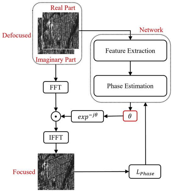
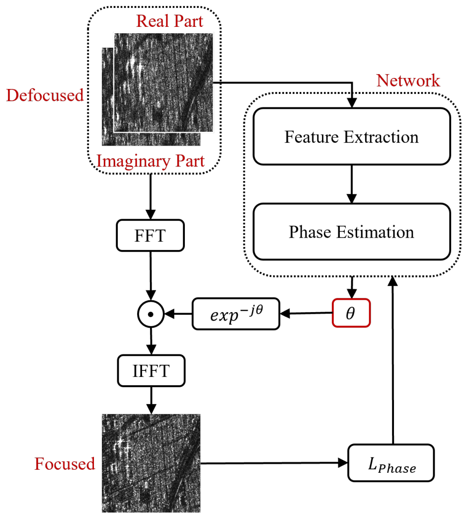
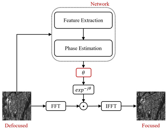
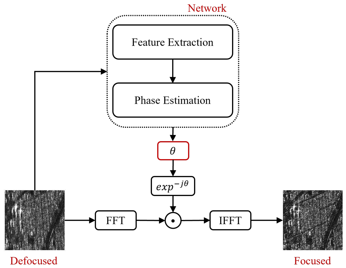
In SAR imaging, inaccurate orbit or navigation data precludes the effective estimation of the equivalent velocity of the radar, thereby introducing phase errors in the azimuth direction and causing image defocusing [56]. Recently, Deep Neural Networks (DNNs) have exhibited superior performance in SAR image processing, leveraging their potent nonlinear mapping capabilities. Building upon this, we propose a deep learning-based autofocus method, termed DeepAutofocus. The workflow of the network training stage is shown in Figure 1, and the process for the testing stage is illustrated in Figure 2. This approach employs a DNN to directly predict the phase error curve from a defocused complex-valued image, which is subsequently compensated for in the range-Doppler domain to yield a focused complex-valued image.
Figure 1.
The workflow of the proposed autofocus scheme in training stage.
Figure 2.
The process of the proposed autofocus scheme for the testing stage.
Specifically, with the defocused complex-valued image as input, the phase error is first obtained through the feature extraction module and phase estimation module based on DNN. Subsequently, phase compensation is performed on the range-Doppler domain data, with the specific operation expressed as follows:
where represents the azimuth Fourier Transform, and is the inverse operation. denotes the diagonalization operation, constitutes the phase compensation term, and the final output is the focused complex-valued image .
2.3. Phase Estimation Scheme
Unlike existing autofocusing networks that rely on estimating coefficients of predefined high-order polynomials, we propose a nonparametric phase estimation scheme based on Cubic B-splines. While polynomial models often suffer from parameter redundancy and the Runge phenomenon (severe oscillations at the boundaries), B-splines provide excellent local control and guarantee continuity. This makes them highly suitable for modeling the smooth, complex, and nonlinear physical phase errors induced by platform motion.
Instead of directly predicting the phase value for each azimuth pixel, the proposed network is designed to predict a set of sparse control points, which uniquely define the continuous B-spline curve. Assuming the azimuth aperture is uniformly partitioned by K control points , the phase error curve at any azimuth index can be expressed as a linear combination of cubic B-spline basis functions:
where represents the cubic B-spline basis function of degree 3.
To seamlessly integrate the B-spline formulation into the deep learning framework while supporting efficient backpropagation, we transform Equation (3) into a matrix multiplication. During the initialization phase, a parameter-free B-spline basis matrix is precomputed using the predefined knots. The element represents the weight of the basis function evaluated at the discrete azimuth coordinate n. Consequently, the entire continuous phase error vector can be efficiently reconstructed through a single matrix multiplication:
where the control points vector is directly generated by the output layer of our DeepAutofocus network. This matrix-based B-spline reconstruction strategy is entirely differentiable, thereby allowing the network to capture complex, arbitrary global phase error patterns with minimal computational overhead and optimal smoothness.
2.4. Autofocus Network Structure
2.4.1. Multiscale Feature Extraction Network
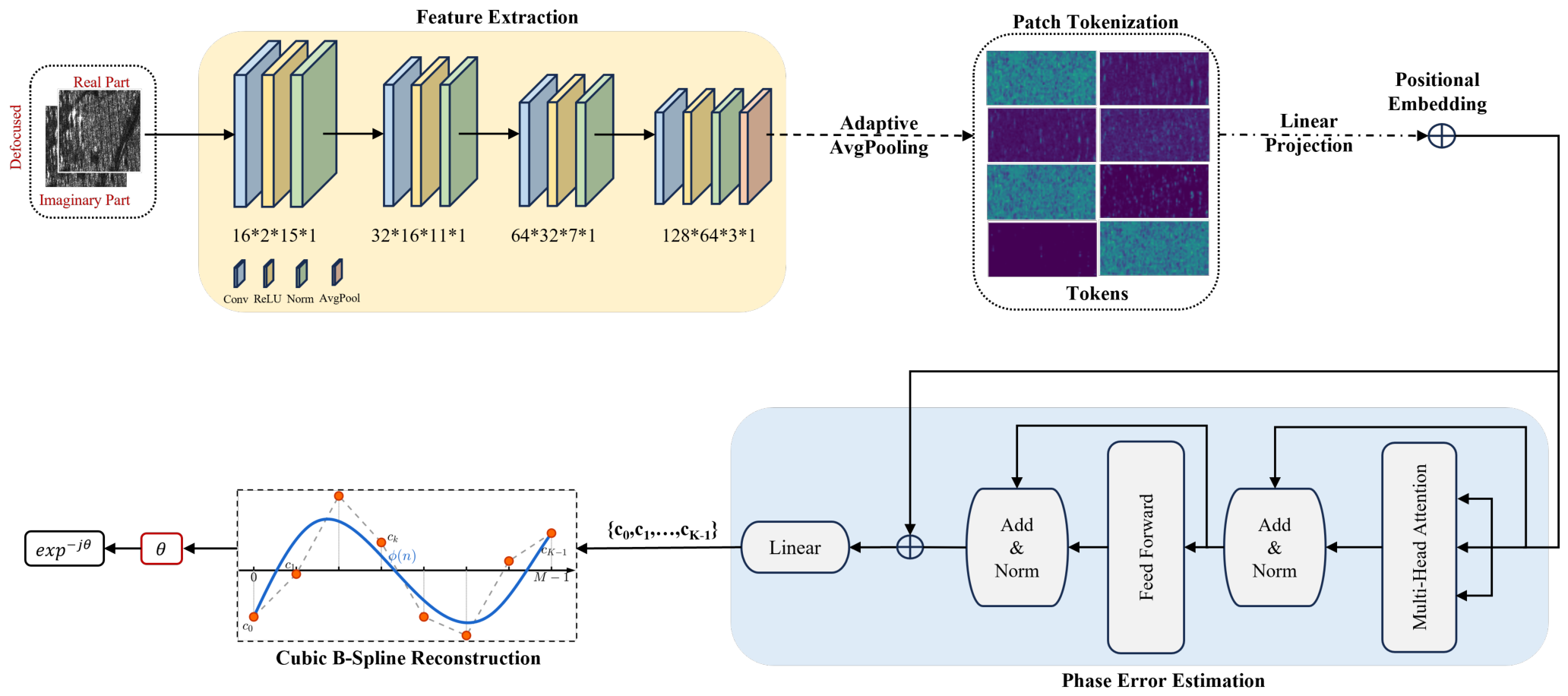
Convolutional Neural Networks (CNNs) extract local spatial features from input data through multiple layers of convolution and pooling operations, providing high-quality feature representations for subsequent tasks [57,58,59,60]. They are widely applied in image processing and pattern recognition tasks [61,62]. Therefore, in this paper, we propose a multiscale convolutional neural network for feature extraction as shown in Figure 3. The input data consists of complex-valued tensors with dimensions B × M × N × 2, where B denotes the batch size, M and N respectively denote the azimuth and range dimensions, and 2 denotes the channels for the real and imaginary parts. The feature extraction network is composed of multiple convolutional layers, each followed by Instance Normalization(IN) and LeakyReLU activation function, to enhance feature robustness and nonlinear representation capability. The convolutional layers are configured with an increasing number of channels (e.g., 16, 32, 64, 128) and convolutional kernels of different sizes (e.g., 15, 11, 7, 3) to capture multiscale spatial features.
Figure 3.
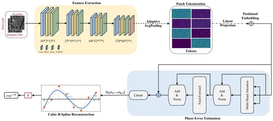
The architecture of the proposed DeepAutofocus network. The model primarily comprises a multi-scale CNN and a Patch Transformer. Specifically, the multi-scale CNN is utilized to extract local features, which are then tokenized into sequential patches. Subsequently, a Transformer encoder is employed to capture the global evolution patterns of the phase errors. Finally, the continuous phase error curve is reconstructed via cubic B-spline generation.
Specifically, the convolution operation can be expressed as:
where is the output of the layer, and are the convolutional kernel weights and biases, respectively. ∗ denotes the convolution operation. In the final stage of feature extraction, an adaptive average pooling layer is employed to compress the spatial dimensions to 1 × 1, generating a compact feature representation for each sample with the shape B × C × 1 × 1, where C is the number of channels. This design ensures that the model can extract hierarchical spatial features from SAR images, which are crucial for subsequent phase error estimation.
In the final stage of feature extraction, inspired by the traditional sub-aperture MDA, an adaptive average pooling layer is employed to compress the spatial dimensions to , where P denotes the number of patch tokens. This operation generates a sequence of localized feature representations with the shape for each sample, where C is the number of channels. Physically, this patch-based partition design is equivalent to dividing the full-aperture SAR data into P sub-apertures along the azimuth direction. Consequently, this design not only preserves the spatial structural sequence of the hierarchical features extracted from SAR images, but also emulates the sub-aperture segmentation process at the feature level, providing a fine-grained sequence foundation for the subsequent Transformer-based phase error estimation.
2.4.2. Phase Error Estimation Network
In the traditional MDA, phase error estimation relies on computing the cross-correlation between adjacent sub-aperture images. Conversely, the Transformer is a prominent model based on the attention mechanism, excelling at capturing long-range dependencies within sequences through self-attention, which essentially functions as a generalized global cross-correlation [63,64,65,66,67,68]. Inspired by this, we propose a Patch-based Transformer encoder module designed to precisely model the global nonlinear relationships of azimuth phase errors from the extracted sub-aperture feature sequence, as illustrated in Figure 3.
First, the feature tensor output by the multiscale feature extraction network is squeezed and transposed to form a feature sequence , where P is the number of patches and C is the channel dimension. To unify the sequence dimensions for the Transformer, is mapped to a fixed-dimension embedding space via a linear projection layer. Furthermore, since the self-attention mechanism is permutation-invariant, a learnable positional embedding is introduced to explicitly preserve the absolute positional order of each sub-aperture within the full aperture. This tokenization and embedding process is formulated as:
where is the linear projection weight, and is the positional embedding parameter initialized by a truncated normal distribution.
Subsequently, the embedded sequence is fed into the Transformer encoder, which comprises multiple stacked layers of multi-head self-attention (MSA) and feed-forward networks (FFN). For each attention head h, the self-attention is calculated as follows:
where ,, are the query, key, and value matrices generated from the input sequence, and is the scaling factor. By performing the matrix multiplication , the network adaptively computes the attention weights between any two sub-aperture features. This enables the model to capture the overall evolutionary patterns of complex, high-order phase errors under a global receptive field.
To enhance gradient flow and promote feature reuse, a residual connection is applied at the output of the Transformer by adding the initial projected sequence to the Transformer’s output:
Finally, the sequence is flattened along the patch and embedding dimensions to form a comprehensive global feature representation . A regression head composed of a linear layer decodes this flattened vector to predict the phase values of the segment endpoints:
where and are the weight and bias matrices of the regression head, respectively. As described in Section II-C, these predicted endpoint phase values are subsequently reconstructed into the complete, continuous full-aperture phase error curve through non-uniform Chebyshev linear interpolation.
2.4.3. Loss Function
The network is trained using a phase error loss function, focusing on optimizing the accuracy of phase error prediction. The phase error loss measures model performance by calculating the mean squared error (MSE), defined as:
where and are the predicted phase and true phase values for the sample at sampling point m, respectively.
Discussion. Although obtaining a high-quality focused image is the ultimate objective of SAR autofocusing, directly adopting image quality metrics (such as image entropy) as the loss function in an end-to-end network exhibits significant limitations. First, image entropy is a highly non-convex function with respect to phase errors. During the middle and late stages of network training, when the image reaches a partially focused state, the value of global image entropy tends to enter a plateau with marginal variations—a phenomenon similarly reflected in the quantitative data of our subsequent experiments (e.g., Table 1 and Table 2). At this juncture, the global entropy becomes extremely insensitive to residual, weak high-order phase errors, causing the gradients to rapidly approach zero. This premature gradient vanishing forces the network to stop learning before the residual errors are completely eliminated, trapping the model in a sub-optimal local minimum. In contrast, the phase MSE loss adopted in this article imposes strict, point-to-point direct supervision on the phase error curve at the physical level. As long as a minute residual error exists, the MSE provides a stable and continuous gradient flow, compelling the network to continually learn and effectively avoiding the entropy-based local minima trap.
Table 1.
The quantitative comparison results with the different existing autofocusing algorithms on the ALOS-Simpoly Dataset. The best result is boldfaced, and the second best is underlined.
Table 2.
Target-to-Background Ratio (TBR) Metrics for deep learning-based SAR Autofocusing on Sparse Scenes.
3. Results
This section details the evaluation metrics, dataset construction process, and comparative experiments with existing autofocusing methods. Additionally, it includes ablation studies and adaptability experiments to comprehensively evaluate the performance of our method. All experiments were conducted on the same high-performance workstation equipped with an NVIDIA Tesla A100 GPU.
3.1. Performance Metrics
To quantitatively validate the performance of SAR image autofocusing algorithms, this paper adopts image entropy and image contrast as the core evaluation metrics. These two metrics are widely-used standards in the field of SAR image quality assessment.
Image entropy reflects the degree of compactness in the pixel intensity distribution of an image. A smaller entropy value indicates a better-focused image. For a complex SAR image I, its image entropy G is calculated as follows:
where ln is the natural logarithm and P is defined as:
Image contrast is a metric that measures the difference between bright and dark regions in an image. A higher contrast value indicates that the image has sharper details and textures, which means better focusing effect. Image contrast, denoted as O, is typically defined as the ratio of standard deviation to the mean of the image magnitude. It is calculated with the following formula:
where denotes the mathematical expectation operator and is the magnitude of image I.
3.2. Dataset Construction
3.2.1. ALOS-RealPE Dataset
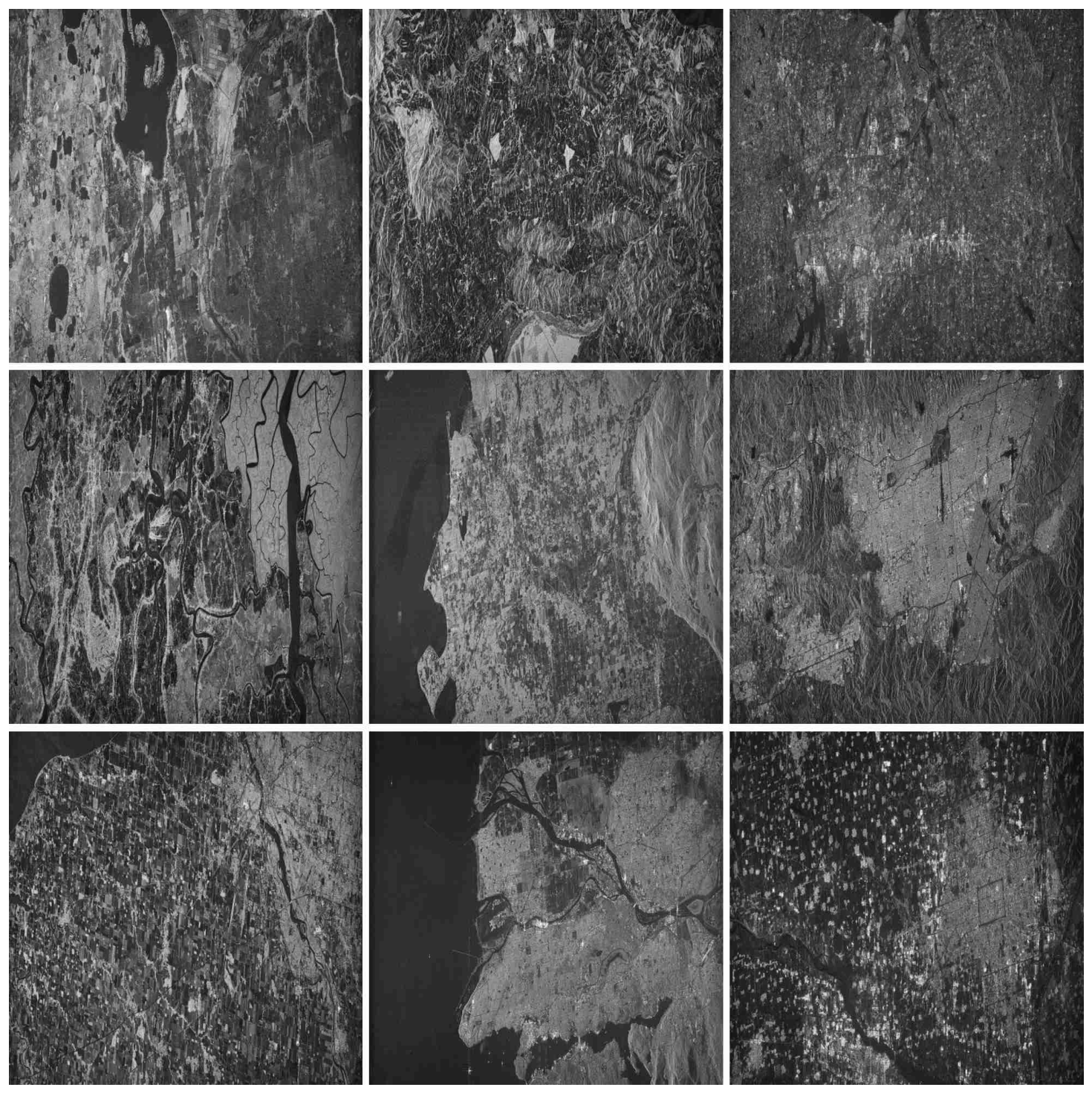
The original images of this dataset were acquired by the Advanced Land Observing Satellite (ALOS, L-band) of Japan. The visualizations of the original focused ALOS scenes used in our experiments are shown in Figure 4. When constructing the defocused dataset, starting from the physical imaging mechanism, we introduce velocity deviations by directly modifying the equivalent radar velocity parameter, which consequently leads to image defocusing. The autofocusing APEs generated by this physical parameter perturbation are dominated by second-order errors, while naturally coupling with higher-order error components, highly replicating the defocusing characteristics in real-world scenarios.
Figure 4.
The visualization of the ALOS datasets. All images were generated using the conventional Range-Doppler algorithm under precise equivalent velocity conditions.
3.2.2. ALOS-Simpoly Dataset
This dataset is also based on the ALOS satellite data but employs a mathematical model-based error injection strategy. In this dataset, we directly generate higher-order polynomial coefficients and inject complex phase errors into the signals within the Range-Doppler domain. Compared to RealPE, these synthesized errors explicitly blend second-order and substantial higher-order error components, aiming to simulate more extreme and nonlinear defocusing conditions.
3.2.3. RADARSAT-1 Dataset
This dataset originates from RADARSAT-1 (C-band) of the Canadian Space Agency. Featuring completely different operating bands and observed scenes from ALOS, this dataset is specifically utilized to verify the cross-platform adaptability of the models. Regarding the APE simulation mechanism, this dataset adopts the same strategy as ALOS-Simpoly (Simulated Polynomial), which directly generates and applies polynomial error coefficients in the Range-Doppler domain. However, in terms of the error component distribution, this dataset is configured with a dominant proportion of second-order errors, accompanied by a certain degree of higher-order error perturbations.
3.3. Comparison with Existing Autofocusing Methods
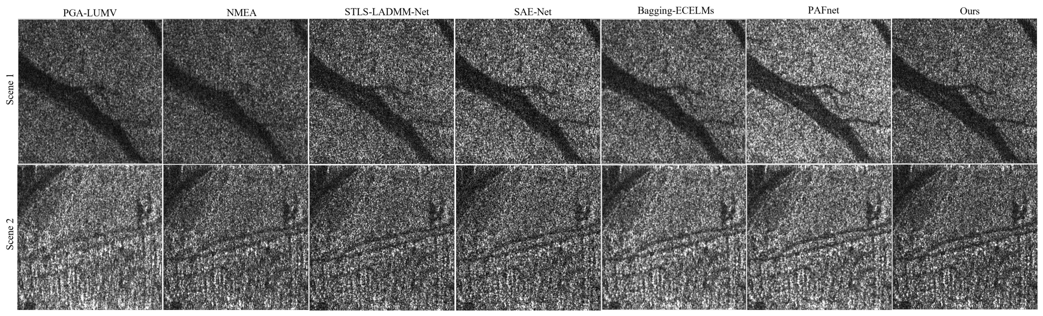
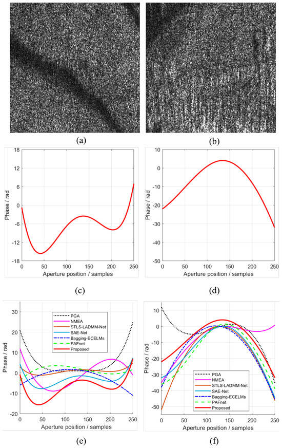
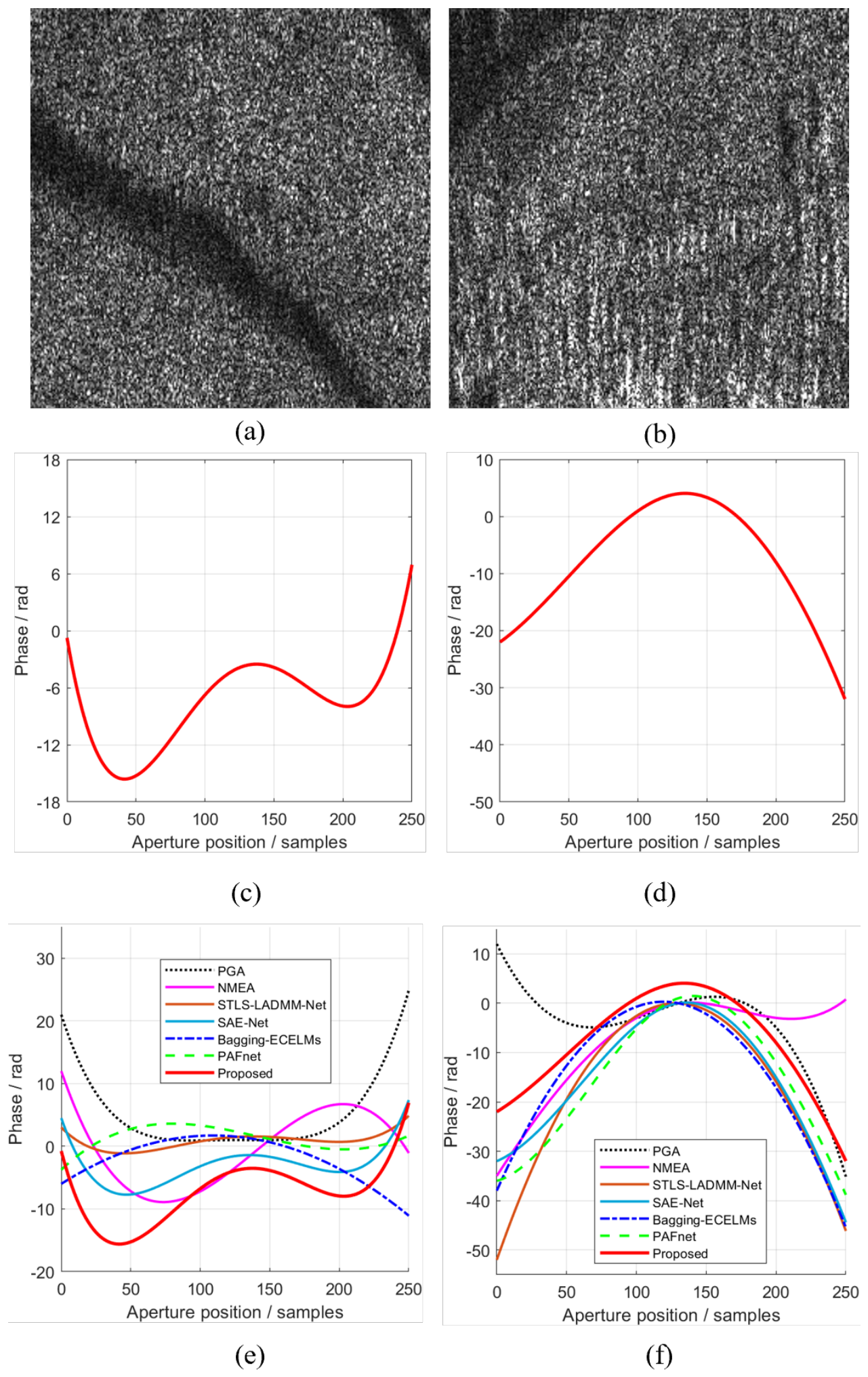
To comprehensively evaluate the performance of the proposed method, we conducted comparative experiments on the ALOS-Simpoly dataset against several mainstream autofocusing algorithms. The comparative baselines include traditional methods (PGA-ML, PGA-LUMV, NMEA), deep unfolding network (DUN)-based methods (STLS-LADMM-Net, SAE-Net), and convolutional neural network (CNN)-based methods (Bagging-ECELMs, PAFnet). Figure 5 illustrates the qualitative imaging results of the various algorithms across two different SAR scenes. From a visual perspective, compared with the original defocused images, the traditional methods (PGA-ML, PGA-LUMV, and NMEA) improve the clarity of target contours to a certain extent. However, pronounced residual defocus blurring remains across the overall images. The deep learning-based methods further enhance the focusing performance. Among them, PAFnet and SAE-Net exhibit commendable visual quality, whereas Bagging-ECELMs still demonstrates inadequacies in the reconstruction of fine textures. In contrast, the proposed method achieves superior focusing quality in both scenes. Not only are the target edges rendered sharply, but the fine structures of the terrain and dominant scattering points are also faithfully reconstructed. To reveal the underlying physical mechanisms driving the aforementioned discrepancies in visual quality, Figure 6 provides a direct visualization of the phase error estimation results obtained by various algorithms across the two scenes. Figure 6c,d depict the ground-truth phase error curves, while Figure 6e,f present a comparison of the curves predicted by the respective algorithms. It is clearly observable that the estimation curves of traditional methods deviate significantly from the ground truth and are highly susceptible to severe oscillations at the aperture boundaries. Although existing deep learning methods manage to capture the general trends of the curves, they exhibit pronounced under-fitting and local mismatches when confronted with complex errors characterized by higher-order nonlinear fluctuations. In stark contrast, the curves estimated by the proposed method not only align closely with the complex ground-truth errors but also effectively circumvent the Runge’s phenomenon at the boundaries. Table 1 tabulates the quantitative comparison results of the respective autofocusing algorithms, where the time metric denotes the average inference time per single image. As observed from the Table 1, the performance of the PGA-based algorithms among the traditional methods is heavily contingent upon the presence of dominant scattering points within the scene, leading to degraded overall performance and prolonged inference times. Although NMEA yields better focusing quality among the traditional methods, it incurs a further increase in inference time. Among the deep learning-based methods, SAE-Net attains the second-best image quality. However, its excessively long inference time renders it impractical for real-world applications. Conversely, while CNN-based methods possess exceptionally fast inference speeds, there remains room for improvement regarding their image quality. Notably, the proposed method achieves the optimal performance in terms of image quality metrics while maintaining a competitive advantage in computational efficiency. In summary, compared with existing algorithms, the proposed method achieves an optimal trade-off between imaging quality and computational speed for SAR image autofocusing tasks.
Figure 5.
Comparisons of the focusing results obtained by different methods for the two scenes. The first and second rows show the focusing results for Scene 1 and Scene 2, respectively. From left to right, the columns present the results processed by PGA-LUMA, NMEA [36], STLS-LADMM-Net [52], SAE-Net [53], Bagging-ECELMs method [54], PAFnet method [55], and the proposed method.
Figure 6.
Defocused images of the two scenes and comparisons of the phase error estimation. (a) Defocused image of Scene 1. (b) Defocused image of Scene 2. (c) True phase error curve of Scene 1. (d) True phase error curve of Scene 2. (e) Estimated phase error curves of different comparative methods for Scene 1. (f) Estimated phase error curves of different comparative methods for Scene 2.
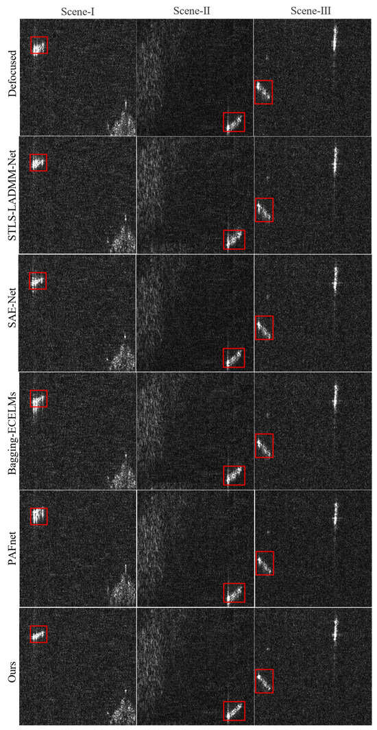
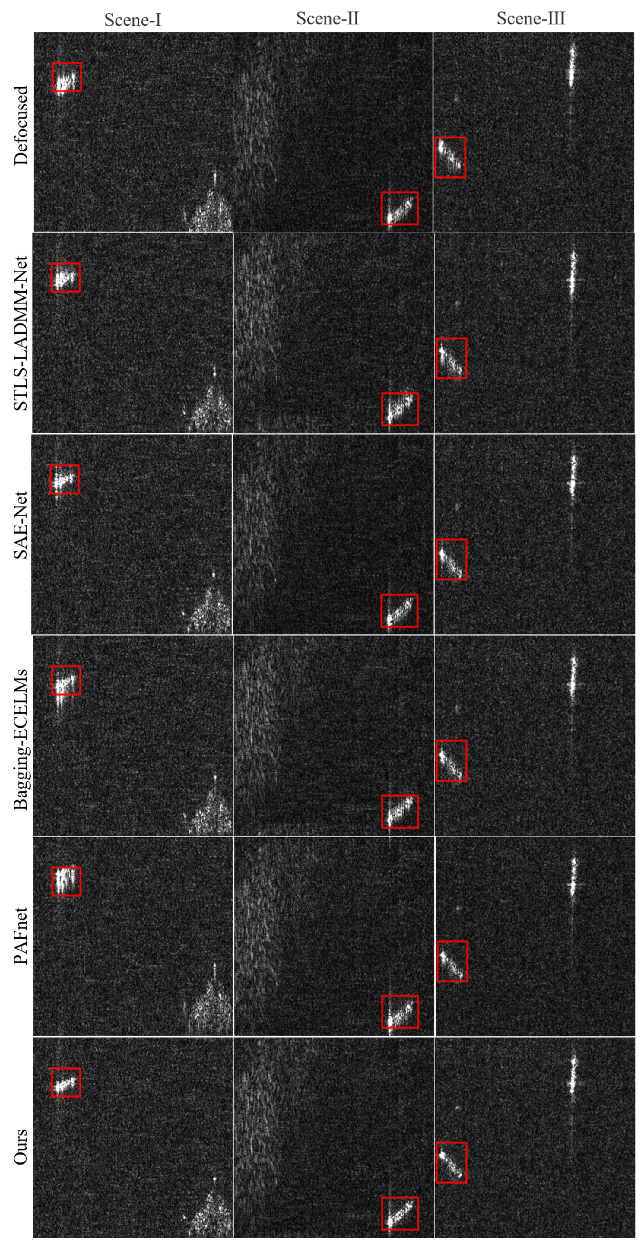
To further demonstrate the superiority of the proposed method, three representative sparse scenes (Scene-I to Scene-III) are selected for comparative experiments. The selected baselines encompass two mainstream deep learning frameworks: deep unfolding network (DUN)-based methods (STLS-LADMM-Net and SAE-Net) and convolutional neural network (CNN)-based methods (Bagging-ECELMs and PAFnet). Figure 7 visually illustrates the qualitative autofocusing results of the different methods. Specifically, the DUN-based methods can effectively recover the principal structures of the targets, yet they still leave room for improvement in edge sharpening. On the other hand, although the CNN-based methods can reconstruct the general structures, they fail to highly concentrate the target energy, resulting in slight defocusing artifacts. In contrast, the proposed method achieves the best visual quality across all three scenes, characterized by highly concentrated target energy and sharp, clear target contours. Target-to-Background Ratio (TBR) is a commonly used evaluation metric in sparse imaging [69]. Table 2 further presents the quantitative evaluation results in terms of the Target-to-Background Ratio (TBR) across the three scenes. The quantitative trends align closely with the visual observations in Figure 7. Compared to both the DUN-based and CNN-based baselines, the proposed method yields the highest metric values in all test scenes. Consequently, both qualitative and quantitative results consistently demonstrate that the proposed method can more effectively concentrate target energy in sparse SAR image autofocusing tasks, achieving the best performance compared to existing deep learning-based methods.
Figure 7.
Autofocusing results of different deep learning-based methods on three sparse SAR scenes. From left to right, the columns correspond to Scene-I, Scene-II, and Scene-III. From top to bottom, the rows display the original defocused images, and the focused results processed by STLS-LADMM-Net [52], SAE-Net [53], Bagging-ECELMs [54], PAFnet [55], and the proposed method, respectively.
It is worth discussing that in Table 1 and Table 3, while the numerical increments in image contrast and entropy achieved by the proposed method appear less pronounced than the visual enhancements, variations of this magnitude actually signify substantial improvements in image quality. First, both contrast and image entropy are global statistical metrics calculated over all pixels. In realistic SAR scenes, low-scattering background regions (e.g., sea surfaces, flat terrains, or shadow areas) dominate the image frame, whereas focus-sensitive strong scatterers and high-frequency texture edges occupy only a minimal fraction of the pixels. Consequently, even if the focusing quality of local targets is significantly improved, the resulting numerical variations are inevitably diluted by the massive number of background pixels. Under such a highly imbalanced pixel distribution, the capability to further improve global contrast physically indicates that the proposed network successfully compresses and focuses the dispersed sidelobe energy around the targets into the mainlobe center. Second, as shown in Table 2, the local Target-to-Background Ratio (TBR) achieves a significant improvement of approximately 1 to 3 dB. By excluding the interference of the global background, this metric strongly corroborates the aforementioned argument, which also highly aligns with the sharper and clearer visual results presented in Figure 5 and Figure 7.
Table 3.
The quantitative comparison results with the autofocusing algorithms based on deep learning on the ALOS-Simpoly Dataset.
The aforementioned experiments demonstrate the superiority of the proposed method in terms of overall focusing quality and computational efficiency. To further investigate the profound impact of parametric versus non-parametric modeling mechanisms on focusing performance, we conduct an in-depth mechanistic comparison between our method and PAFnet. As a highly representative deep learning-based autofocusing approach, PAFnet adopts a “divide-and-conquer” philosophy, utilizing cascaded focusers to explicitly handle polynomial phase errors of specific orders (e.g., 2nd–3rd and 4th–5th orders). This conceptual framework provided valuable inspiration for our work in addressing complex phase errors. However, this parametric, fixed-order progressive strategy exhibits significant limitations in practical applications. Its effectiveness is heavily contingent upon the actual presence of substantial phase errors at the corresponding orders within the input data. When phase errors of a specific order (e.g., 4th–5th order) are inherently weak or absent, enforcing polynomial fitting not only incurs superfluous computational overhead but also triggers severe over-fitting and error accumulation. As evidenced in Table 3, when processing the ALOS-Simpoly dataset, PAFnet’s Focuser-2 (responsible for correcting 4th–5th order errors) failed to further optimize the image. Instead, the unwarranted forced fitting interfered with the focusing process, resulting in an unexpected increase in image entropy (from 9.92 to 9.94). In stark contrast, the proposed method fundamentally circumvents the rigid constraints of predefined polynomial models. By employing a data-driven, non-parametric B-spline strategy, the model is empowered to adaptively fit arbitrary and complex error curves. As demonstrated in Table 3, our method effectively eradicates the risk of error propagation inherent in cascaded structures, achieving superior evaluation metrics in a highly robust manner.
3.4. Ablation Study
3.4.1. Convolution Kernel Size
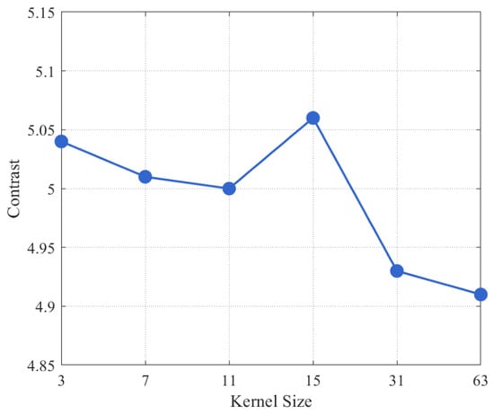
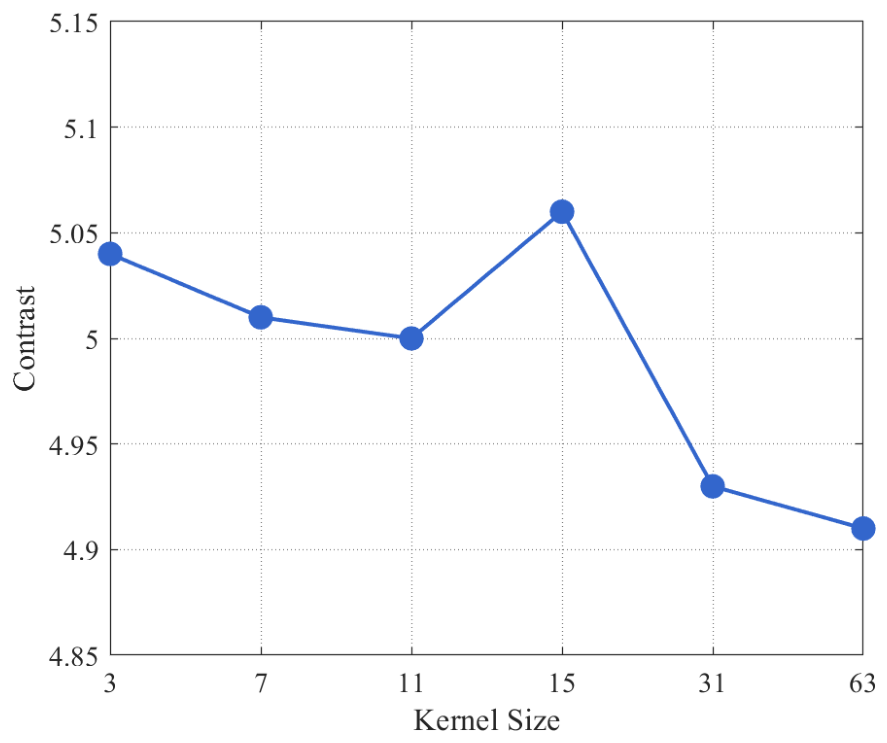
The size of a convolution kernel defines the scale of its receptive field, thereby influencing the capacity of the model to capture multi-scale information [70,71,72,73,74,75,76]. We conducted a comparative experiment to determine the optimal kernel size in the azimuth direction on ALOS-Simpoly Dataset. For this experiment, the network architecture was simplified: the output channels of each convolutional layer were fixed at 64, the range-direction kernel size was set to 1, and the azimuth-direction kernel size was selected from the set {3, 7, 11, 15, 31, 63}. As illustrated in the Figure 8, the results show that kernel size significantly impacts model performance. The DeepAutofocus model attained peak focusing performance with a kernel size of 15. However, larger kernels also substantially increase the computational load and inference time. Consequently, to balance performance with efficiency, we opted against a single large kernel. Instead, the final version of DeepAutofocus incorporates a multi-scale kernel design to achieve a balance between performance and efficiency.
Figure 8.
The effect of convolution kernel size on focusing performance on ALOS-Simpoly Dataset. The horizontal axis represents the kernel size, and the vertical axis shows the image contrast (blue line).
3.4.2. Number of Breakpoints
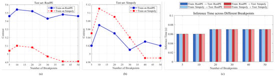
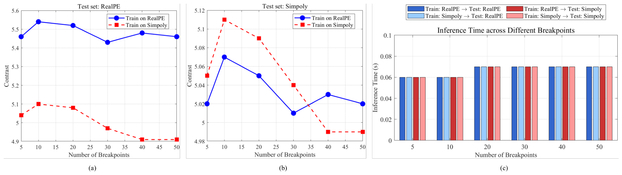
The number of breakpoints directly determines the degrees of freedom (DoF) of the non-parametric B-spline curve fitting, which in turn affects the reconstruction accuracy of complex phase errors. To explore the optimal breakpoint configuration, an offline hyperparameter evaluation strategy is adopted in this paper. Specifically, independent networks configured with varying numbers of breakpoints are trained, and their convergence peaks of focusing performance on the test set are compared to empirically determine the optimal parameters. The evaluation results are presented in Figure 9. As indicated by the quantitative curves in Figure 9a,b, a limited number of breakpoints (e.g., ) restricts the DoF of the spline curve, making it difficult to accurately characterize complex high-order nonlinear phase errors and consequently leading to degraded image contrast. As the number of breakpoints increases to the range of 10 to 20, the model achieves optimal focusing quality, indicating that the spline curve can precisely approximate the true global phase distribution. However, when the number of breakpoints increases further , the excessive DoF makes the model susceptible to overfitting local noise. This induces local high-frequency oscillations in the phase curve, which inevitably results in a downward trend in image contrast. It is worth discussing that, although employing more than 20 breakpoints leads to overfitting under the current data distribution, this may not hold true for SAR platforms operating in extremely adverse environments (e.g., severe mechanical vibrations of lightweight UAVs or intense atmospheric turbulence). Under such conditions, the actual phase errors are often corrupted by dense and severe high-frequency oscillating components. Consequently, a smaller number of breakpoints would run the risk of underfitting, necessitating a further increase in the breakpoint quantity to adequately capture the high-frequency local distortions. Furthermore, as illustrated in Figure 9c, as the dimension of breakpoints expands, the inference time per image increases only marginally from approximately 0.06 s to stabilize around 0.07 s. This indicates that increasing the number of breakpoints does not introduce significant computational overhead. In fact, the search for the optimal breakpoint configuration incurs computational costs solely during the offline evaluation phase, imposing minimal burden on the online inference efficiency. In practical deployments, when transferring the pre-trained model and its corresponding breakpoint configuration to other SAR datasets with distinct error characteristics, the network can rapidly adapt to the new error distributions via few-shot fine-tuning, thereby eliminating the need for retraining from scratch. Comprehensively balancing the phase error compensation accuracy, robustness, scene adaptability, and computational efficiency, the experimental results demonstrate that setting the number of breakpoints within the range of 10 to 20 enables the network to achieve optimal SAR image autofocusing performance while maintaining highly efficient inference.
Figure 9.
Impact of the number of breakpoints on focusing performance and computational efficiency. (a) Image contrast versus the number of breakpoints on the RealPE test set. (b) Image contrast versus the number of breakpoints on the Simpoly test set. (c) Average inference time per image across different train/test configurations.
Although the current empirical selection of the number of breakpoints achieves a favorable balance, different SAR systems exhibit varying degrees of error complexity. Future work could explore adaptive setting schemes, such as employing an attention mechanism to dynamically determine the optimal number of control points based on the severity of initial image defocusing or specific SAR platform parameters. Alternatively, regularization strategies could be investigated, such as incorporating a roughness penalty into the loss function to prevent overfitting.
3.4.3. Network Architectures
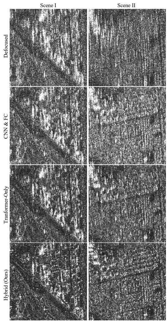
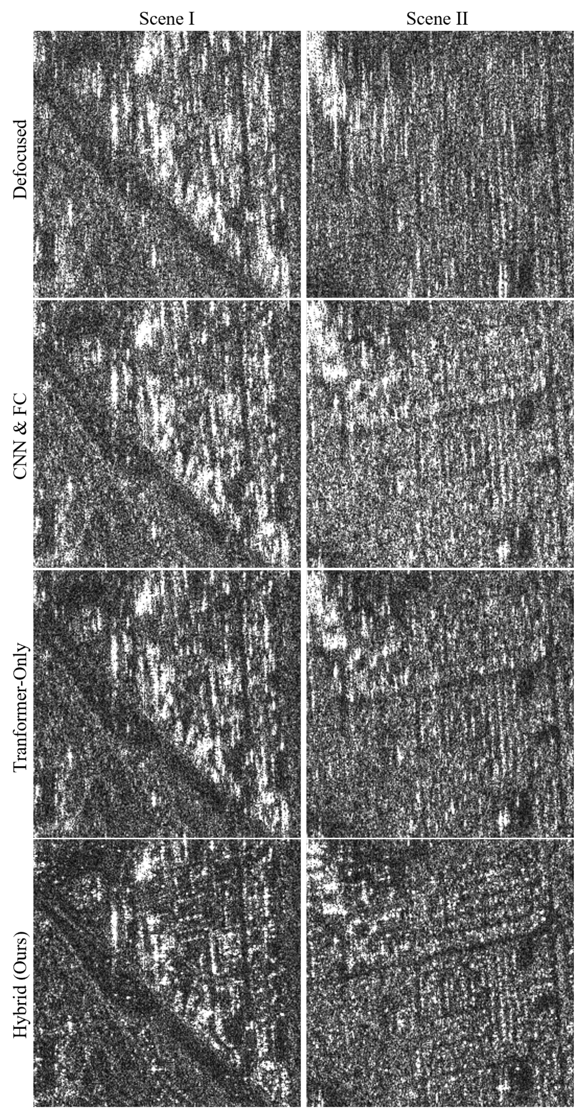
To validate the effectiveness of the proposed DeepAutofocus hybrid architecture, we conducted an ablation study on the network architectures in the ALOS-Simpoly dataset. As presented by the quantitative data in Table 4, although the Multi-scale CNN & FC architecture, which relies solely on local receptive fields, achieves extremely fast inference, its improvement in focusing metrics remains highly limited. Meanwhile, the Single-Conv & Transformer architecture, lacking the support of multi-scale local features, also experiences a significant performance degradation. In contrast, the proposed hybrid architecture achieves the optimal focusing performance while maintaining highly efficient inference. The visual comparisons in Figure 10 intuitively illustrate that both the Multi-scale CNN & FC and Single-Conv & Transformer networks retain pronounced defocus blur when restoring fine textures. Conversely, by leveraging the CNN for the fine-grained extraction of multi-scale local spatial features and the Transformer for the global modeling of long-range dependencies across subapertures, the proposed hybrid architecture significantly enhances the image focusing quality. It reconstructs the complex details and structures of the scene with remarkable sharpness, thereby thoroughly substantiating the necessity and rationality of the proposed network design.
Table 4.
Quantitative evaluation of different network architectures in the ablation study on the ALOS-Simpoly Dataset.
Figure 10.
Visual comparison of autofocusing results using different network architectures in the ablation study on ALOS-Simpoly Dataset. From top to bottom, the rows display the original defocused SAR images, and the focused results processed by the Multi-scale CNN & FC, the Single-Conv & Transformer, and the proposed Hybrid network, respectively. The left and right columns correspond to Scene I and Scene II.
3.5. Adaptability Experiments
3.5.1. Cross-Domain Adaptability Experiments
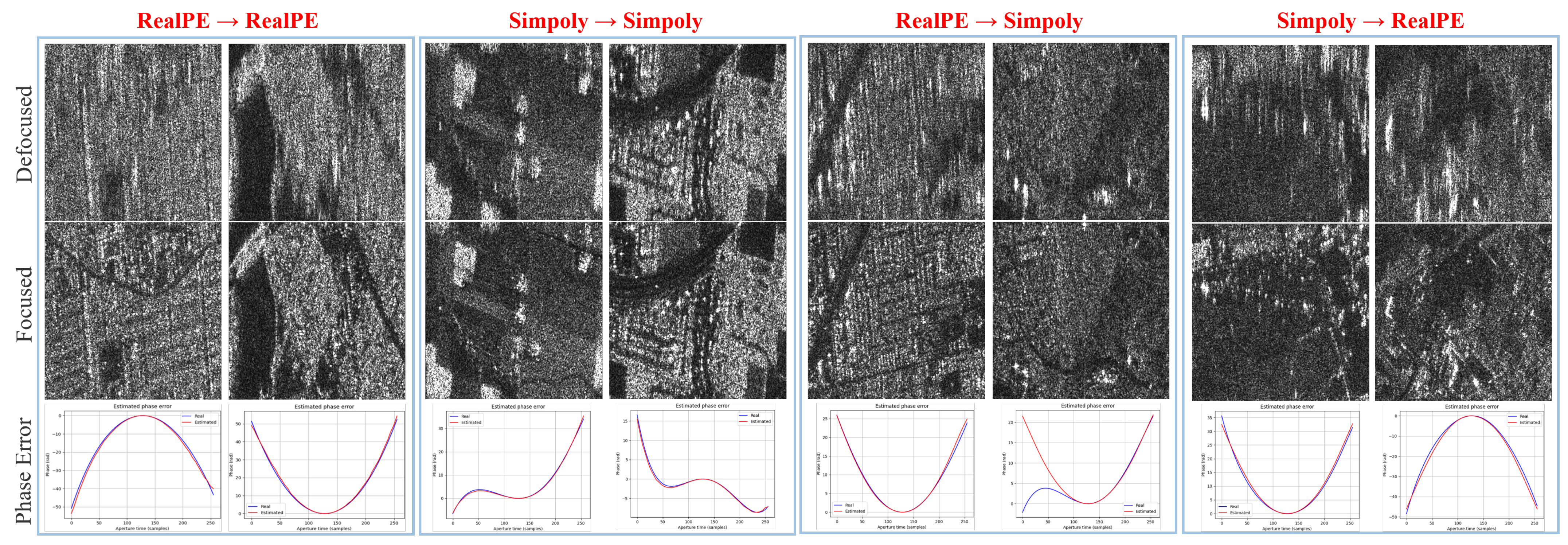
To further verify the adaptability and robustness of the proposed nonparametric phase error estimation strategy, cross-domain validation experiments are conducted between the ALOS-RealPE and ALOS-Simpoly datasets, with the qualitative visualization results shown in Figure 11. The experiments encompass two intra-domain tests (RealPE→RealPE, Simpoly→Simpoly) and two highly challenging cross-domain tests (RealPE→Simpoly, Simpoly→RealPE). As observed from the focused images in the second row of Figure 11, even in cross-domain scenarios with significant discrepancies in the error distribution characteristics between the training and testing data, the DeepAutofocus model can still effectively eliminate the defocus blur, restoring clear scene textures and target edges with high fidelity. Furthermore, the phase error estimation results in the third row of Figure 11 indicate that, whether generalizing from the physically derived real errors (RealPE) to the mathematically simulated errors containing numerous high-order components (Simpoly), or vice versa, the predicted phase error curves (red lines) coincide well with the ground-truth curves (blue lines). Meanwhile, the local oscillations at the boundaries are effectively suppressed. Objectively speaking, in the highly challenging RealPE→Simpoly cross-domain scenario, the fitting curves of a few testing samples exhibit slight local deviations (as shown in the right side of the third group in Figure 11). Fundamentally, this is primarily attributed to the significant data distribution discrepancy between the two datasets: the error distribution of the RealPE training set is dominated by second-order components, whereas the Simpoly testing set contains abundant high-order components. Faced with such a severe data distribution shift, the model’s adaptability regarding unseen high-order details is inevitably compromised to some extent. Nevertheless, even under such stringent conditions, the model still accurately captures the global evolution trend of the phase errors, thereby ensuring no noticeable degradation in the final focusing quality. In summary, benefiting from the data-driven B-spline fitting mechanism and the exceptional global receptive field of the Transformer architecture, the proposed method avoids overfitting to any single error distribution pattern. Instead, it successfully learns the underlying nonlinear mapping relationships from defocused image features to phase errors, demonstrating strong scene adaptability.
Figure 11.
Visualization of the cross-dataset adaptability of the proposed DeepAutofocus network using the ALOS-RealPE and ALOS-Simpoly datasets. The four main columns correspond to different training and testing configurations (from left to right): trained and tested on RealPE (RealPE→RealPE), trained and tested on Simpoly (Simpoly→Simpoly), trained on RealPE and tested on Simpoly (RealPE→Simpoly), and trained on Simpoly and tested on RealPE (Simpoly→RealPE), with two distinct scenes displayed for each configuration. Row 1 displays the original defocused SAR images. Row 2 shows the corresponding focused images recovered by our method. Row 3 presents the phase error estimation results, where the true phase errors (ground truth) are plotted as blue lines and the estimated phase errors are plotted as red lines. The x-axis and y-axis in the plots represent the aperture time (in samples) and the phase (in rad), respectively.
3.5.2. Cross-Platform Adaptability Experiments
To comprehensively evaluate the robustness and cross-platform adaptability of the proposed method, a challenging cross-dataset testing experiment is conducted in this section. Specifically, the model trained to convergence exclusively on the ALOS-RealPE (L-band) dataset is directly applied to the RADARSAT-1 (C-band) dataset for testing, without any fine-tuning of the network weights, despite the significant difference in feature distributions between the two datasets. Table 5 details the quantitative evaluation results of various comparative methods on the RADARSAT-1 test set. As observed in Table 5, despite the severe domain shift challenge induced by cross-satellite sensors, all the deep learning baselines can improve the quality of the defocused images to varying degrees. Nevertheless, the proposed method continues to exhibit significant superiority, achieving the highest image contrast and the lowest image entropy among all evaluated methods. Such outcomes provide compelling evidence that rather than overfitting to a localized training domain, our model has successfully captured the intrinsic mapping rules underlying phase error compensation.
Table 5.
The adaptability performance of deep learning-based methods on the RADARSAT-1 dataset.
3.6. Computational Complexity and Efficiency Analysis
To comprehensively evaluate the computational complexity and efficiency of the proposed framework, we focus our comparative analysis on PAFnet, as it is the fastest baseline method presented in Table 1. As shown in Table 6, compared to PAFnet, the proposed DeepAutofocus requires significantly fewer parameters and floating-point operations (FLOPs). This demonstrates that the superior focusing accuracy of our hybrid architecture is not achieved by simply stacking network scales, but rather through a more efficient non-parametric design. Specifically, instead of directly tokenizing raw image pixels or dense patches, our architecture delegates the dense spatial processing to a multiscale CNN, which operates with linear complexity. Subsequently, the adaptive pooling layer condenses the hierarchical spatial features into a highly compact sequence of subaperture patch tokens. Through this efficient token-related design, DeepAutofocus successfully circumvents computational complexity explosion [77]. Although the memory access patterns inherent to the Transformer’s attention mechanism result in slightly higher peak GPU memory compared to pure CNNs, these additional overheads remain well within an acceptable range, fully satisfying the practical demands of fast batch processing for SAR imagery.
Table 6.
Computational complexity comparison between different autofocus networks.
4. Discussion
While the proposed DeepAutofocus framework achieves superior focusing quality and computational efficiency, we acknowledge a fundamental limitation of the current approach. The phase-MSE training paradigm necessitates datasets with pre-known phase-error curves, which are typically impossible to acquire in real-world raw SAR measurements. While this supervised approach was essential in this study to explicitly validate the network’s representation power and avoid the severe local minima traps associated with pure image-entropy optimizations, it inherently limits the model’s immediate applicability to completely unannotated SAR data. Therefore, transitioning to self-supervised or label-free learning paradigms represents a critical direction for our future work. By integrating physics-informed constraints or blind deconvolution priors into the loss function, we aim to extend this hybrid architecture to learn directly from challenging, label-free imaging settings [78]. Ultimately, deploying and validating the proposed framework under real measured phase-error conditions will be an essential step to fully realize its potential in practical SAR operations.
5. Conclusions
In this article, we proposed DeepAutofocus, a non-parametric deep learning framework for SAR autofocus, aimed at resolving the performance bottlenecks of existing algorithms under complex phase error conditions. Traditional autofocus algorithms typically suffer from irreconcilable trade-offs among computational efficiency, scene adaptability, and focusing accuracy. Meanwhile, existing DL-based autofocus networks are constrained by their reliance on predefined parametric polynomial models, leading to parameter redundancy and performance degradation. To overcome these limitations, we introduced a physics-inspired subaperture correlation Transformer architecture. This architecture leverages a CNN to extract multiscale local features and incorporates the self-attention mechanism of a Transformer to accurately reconstruct the global dependencies of phase errors across subapertures. Furthermore, we developed a data-driven cubic B-spline piecewise approximation strategy. By directly estimating phase errors from defocused images, this non-parametric strategy effectively circumvents boundary oscillations and significantly enhances the model’s adaptability to complex errors. Comprehensive experimental results on satellite datasets demonstrate that DeepAutofocus possesses strong robustness and adaptability. Compared to traditional algorithms and existing DL methods, the proposed method achieves superior focusing quality, thereby providing a promising data-driven paradigm for the efficient, high-precision, and batch processing of massive SAR imagery.
Author Contributions
Conceptualization, X.L. and J.Z.; methodology, X.L. and J.L.; software, X.L. and J.L.; validation, X.L., H.F. and H.Z.; formal analysis, X.L. and H.F.; investigation, X.L.; resources, H.Z. and J.Z.; data curation, X.L. and H.F.; writing—original draft preparation, X.L.; writing—review and editing, X.L., J.L. and J.Z.; visualization, X.L.; supervision, J.Z.; project administration, J.Z.; funding acquisition, J.Z. All authors have read and agreed to the published version of the manuscript.
Funding
This research received no external funding.
Institutional Review Board Statement
Not applicable.
Informed Consent Statement
Not applicable.
Data Availability Statement
Public ALOS SAR data are acquired from https://search.asf.alaska.edu/ (accessed on 25 May 2018).
Acknowledgments
Our sincere appreciation goes to the anonymous reviewers for their insightful feedback, which proved invaluable in enhancing the quality of our manuscript.
Conflicts of Interest
The authors declare no conflicts of interest.
References
- Huang, C.; Wang, L.; Zhao, L.; Liu, S.; Zou, D.; Liu, G.; Hu, G.; Du, E.; Xiao, Y.; Wang, C.; et al. Potential of c-band sentinel-1 insar for ground surface deformation monitoring in the southern boreal forest: An investigation in the genhe river basin. Int. J. Appl. Earth Obs. Geoinf. 2024, 135, 104302. [Google Scholar] [CrossRef] [Scilit]
- Zhao, H.; Tian, Y.; Wang, J.; Chen, J.; Bao, M.; Jiang, X. Airport runway roughness evaluation using tcp-insar technology. Int. J. Pavement Eng. 2025, 26, 2496335. [Google Scholar] [CrossRef] [Scilit]
- Zhu, W.; Yang, L.; Cheng, Y.; Liu, X.; Zhang, R. Active thickness estimation and failure simulation of translational landslide using multi-orbit insar observations: A case study of the xiongba landslide. Int. J. Appl. Earth Obs. Geoinf. 2024, 129, 103801. [Google Scholar] [CrossRef] [Scilit]
- Yin, J.; Duan, C.; Wang, H.; Yang, J. A review on the few-shot sar target recognition. IEEE J. Sel. Top. Appl. Earth Obs. Remote Sens. 2024, 17, 16411–16425. [Google Scholar] [CrossRef] [Scilit]
- Huang, L.; Liu, G. Convolutional feature aggregation network with self-supervised learning and decision fusion for sar target recognition. IEEE Trans. Instrum. Meas. 2024, 73, 2526714. [Google Scholar] [CrossRef] [Scilit]
- Wang, L.; Yang, Y.; Liu, Z. Multiresolution sar target recognition based on physical attention enhancement and scale distillation. IEEE Trans. Aerosp. Electron. Syst. 2024, 60, 3081–3094. [Google Scholar] [CrossRef] [Scilit]
- Guo, D.; Chen, B.; Zheng, M.; Liu, H. Sar automatic target recognition based on supervised deep variational autoencoding model. IEEE Trans. Aerosp. Electron. Syst. 2021, 57, 4313–4328. [Google Scholar] [CrossRef] [Scilit]
- Liao, X.; Jiang, N.; Zhao, W.; Wang, Z.; Zhu, J. Dynamic deep unfolding network based on content-aware shrinkage for sar sparse imaging. IEEE Geosci. Remote Sens. Lett. 2025, 22, 4005405. [Google Scholar] [CrossRef] [Scilit]
- Pu, W. Deep sar imaging and motion compensation. IEEE Trans. Image Process. 2021, 30, 2232–2247. [Google Scholar] [CrossRef] [Scilit] [PubMed]
- Wu, J.; Pu, W.; An, H.; Huang, Y.; Yang, H.; Yang, J. Learning-based high-frame-rate sar imaging. IEEE Trans. Geosci. Remote Sens. 2023, 61, 5208813. [Google Scholar] [CrossRef] [Scilit]
- Tang, F.; Ji, Y.; Zhang, Y.; Dong, Z.; Wang, Z.; Zhang, Q.; Zhao, B.; Gao, H. Drifting ionospheric scintillation simulation for l-band geosynchronous sar. IEEE J. Sel. Top. Appl. Earth Obs. Remote Sens. 2024, 17, 842–854. [Google Scholar] [CrossRef] [Scilit]
- Li, L.; Ding, Z.; Wang, Y.; Gao, W.; Liu, M.; Zhang, T.; Tian, W.; Zeng, T. Linear-array-mimo sar tomography: An autofocus approach for time-variant and 3-d space-variant motion errors. IEEE Trans. Geosci. Remote Sens. 2022, 60, 5211717. [Google Scholar] [CrossRef] [Scilit]
- Wahl, D.; Eichel, P.; Ghiglia, D.; Jakowatz, C. Phase gradient autofocus-a robust tool for high resolution sar phase correction. IEEE Trans. Aerosp. Electron. Syst. 1994, 30, 827–835. [Google Scholar] [CrossRef] [Scilit]
- Mao, X.; Zhu, D. Two-dimensional autofocus for spotlight sar polar format imagery. IEEE Trans. Comput. Imaging 2016, 2, 524–539. [Google Scholar] [CrossRef] [Scilit]
- Chen, J.; Xiong, R.; Jiang, N.; Xu, G.; Li, R.; Xing, M. An ncs-based wls estimator for airborne microwave photonic sar autofocus. IEEE Geosci. Remote Sens. Lett. 2024, 21, 4016505. [Google Scholar] [CrossRef] [Scilit]
- Kim, J.-W.; Kim, Y.-D.; Yeo, T.-D.; Khang, S.-T.; Yu, J.-W. Fast fourier-domain optimization using hybrid L1–Lp -norm for autofocus in airborne sar imaging. IEEE Trans. Geosci. Remote Sens. 2019, 57, 7934–7954. [Google Scholar] [CrossRef]
- Linnehan, R.; Miller, J.; Asadi, A. Map-drift autofocus and scene stabilization for video-sar. In 2018 IEEE Radar Conference (RadarConf18); IEEE: New York, NY, USA, 2018; pp. 1401–1405. [Google Scholar]
- Wang, G.; Zhang, M.; Huang, Y.; Zhang, L.; Wang, F. Robust two-dimensional spatial-variant map-drift algorithm for uav sar autofocusing. Remote Sens. 2019, 11, 340. [Google Scholar] [CrossRef] [Scilit]
- Calloway, T.; Donohoe, G. Subaperture autofocus for synthetic aperture radar. IEEE Trans. Aerosp. Electron. Syst. 1994, 30, 617–621. [Google Scholar] [CrossRef] [Scilit]
- Mancill, C.; Swiger, J. A map drift autofocus technique for correcting higher order SAR phase errors. In Proceedings of the 27th Annual Tri-Service Radar Symposium Record, Monterey, CA, USA, 23–25 June 1981; pp. 391–400. [Google Scholar]
- Yang, R.; Li, H.; Li, S.; Zhang, P.; Tan, L.; Gao, X.; Kang, X. High-Resolution Microwave Imaging; Springer: Singapore, 2018. [Google Scholar] [CrossRef] [Scilit]
- Callow, H.-J.; Hayes, M.-P.; Gough, P.-T. Stripmap phase gradient autofocus. In Oceans 2003. Celebrating the Past... Teaming Toward the Future (IEEE Cat. No.03CH37492); IEEE: New York, NY, USA, 2003; Volume 5, pp. 2414–2421. [Google Scholar]
- Li, Y.; O’Young, S. Kalman filter disciplined phase gradient autofocus for stripmap sar. IEEE Trans. Geosci. Remote Sens. 2020, 58, 6298–6308. [Google Scholar] [CrossRef] [Scilit]
- Evers, A.; Jackson, J.A. A generalized phase gradient autofocus algorithm. IEEE Trans. Comput. Imaging 2019, 5, 606–619. [Google Scholar] [CrossRef]
- Liu, K.-H.; Wiesel, A.; Munson, D.C. Synthetic aperture radar autofocus based on a bilinear model. IEEE Trans. Image Process. 2012, 21, 2735–2746. [Google Scholar] [CrossRef] [Scilit] [PubMed]
- Wang, J.; Kasilingam, D.; Liu, X.; Zhou, Z. Isar minimum-entropy phase adjustment. In Proceedings of the 2004 IEEE Radar Conference (IEEE Cat. No.04CH37509); IEEE: New York, NY, USA, 2004; pp. 197–200. [Google Scholar]
- Thomas, K.-J.; Alaa, K. Monotonic iterative algorithm for minimum-entropy autofocus. In Proceedings of the Adaptive Sensor Array Processing Workshop, Lexington, MA, USA, 6–7 June 2006; pp. 645–648. [Google Scholar]
- Wang, J.; Liu, X. Sar minimum-entropy autofocus using an adaptive-order polynomial model. IEEE Geosci. Remote Sens. Lett. 2006, 3, 512–516. [Google Scholar] [CrossRef] [Scilit]
- Xiong, T.; Xing, M.; Wang, Y.; Wang, S.; Sheng, J.; Guo, L. Minimum-entropy-based autofocus algorithm for sar data using chebyshev approximation and method of series reversion, and its implementation in a data processor. IEEE Trans. Geosci. Remote Sens. 2014, 52, 1719–1728. [Google Scholar] [CrossRef]
- Berizzi, F.; Corsini, G. Autofocusing of inverse synthetic aperture radar images using contrast optimization. IEEE Trans. Aerosp. Electron. Syst. 1996, 32, 1185–1191. [Google Scholar] [CrossRef] [Scilit] [PubMed]
- Kolman, J. Pace: An autofocus algorithm for sar. In IEEE International Radar Conference, 2005; IEEE: New York, NY, USA, 2005; pp. 310–314. [Google Scholar]
- Yang, J.; Huang, X.; Jin, T.; Xue, G.; Zhou, Z. An interpolated phase adjustment by contrast enhancement algorithm for sar. IEEE Geosci. Remote Sens. Lett. 2011, 8, 211–215. [Google Scholar] [CrossRef] [Scilit]
- Morrison, R.L.; Do, M.N.; Munson, D.C. Sar image autofocus by sharpness optimization: A theoretical study. IEEE Trans. Image Process. 2007, 16, 2309–2321. [Google Scholar] [CrossRef] [Scilit] [PubMed]
- Gao, Y.; Yu, W.; Liu, Y.; Wang, R.; Shi, C. Sharpness-based autofocusing for stripmap sar using an adaptive-order polynomial model. IEEE Geosci. Remote Sens. Lett. 2014, 11, 1086–1090. [Google Scholar] [CrossRef] [Scilit]
- Zeng, T.; Wang, R.; Li, F. Sar image autofocus utilizing minimum-entropy criterion. IEEE Geosci. Remote Sens. Lett. 2013, 10, 1552–1556. [Google Scholar] [CrossRef] [Scilit]
- Zhang, S.; Liu, Y.; Li, X. Fast entropy minimization based autofocusing technique for isar imaging. IEEE Trans. Signal Process. 2015, 63, 3425–3434. [Google Scholar] [CrossRef] [Scilit]
- Cai, J.; Martorella, M.; Chang, S.; Liu, Q.; Ding, Z.; Long, T. Efficient nonparametric isar autofocus algorithm based on contrast maximization and newton’s method. IEEE Sens. J. 2021, 21, 4474–4487. [Google Scholar] [CrossRef] [Scilit]
- Kang, M.-S.; Kim, K.-T. Compressive sensing based sar imaging and autofocus using improved tikhonov regularization. IEEE Sens. J. 2019, 19, 5529–5540. [Google Scholar] [CrossRef] [Scilit]
- Kang, M.-S.; Baek, J.-M. Efficient sar imaging integrated with autofocus via compressive sensing. IEEE Geosci. Remote Sens. Lett. 2022, 19, 4514905. [Google Scholar] [CrossRef] [Scilit]
- Zhang, C.; Baan, M.V.D. Signal processing using dictionaries, atoms, and deep learning: A common analysis-synthesis framework. Proc. IEEE 2022, 110, 454–475. [Google Scholar] [CrossRef] [Scilit]
- Purwins, H.; Li, B.; Virtanen, T.; Schlüter, J.; Chang, S.-Y.; Sainath, T. Deep learning for audio signal processing. IEEE J. Sel. Top. Signal Process. 2019, 13, 206–219. [Google Scholar] [CrossRef] [Scilit]
- Cheung, M.; Shi, J.; Wright, O.; Jiang, L.Y.; Liu, X.; Moura, J.M.F. Graph signal processing and deep learning: Convolution, pooling, and topology. IEEE Signal Process. Mag. 2020, 37, 139–149. [Google Scholar] [CrossRef] [Scilit]
- Liao, X.; Cai, Z.; Chen, J.; Liu, T.; Lai, J.H. Physics-based optical flow estimation under varying illumination conditions. Signal Process. Image Commun. 2023, 117, 117007. [Google Scholar] [CrossRef] [Scilit]
- Zhao, W.; Jiang, N.; Liao, X.; Zhu, J. Hvt-cgan: Hybrid vision transformer cgan for sar-to-optical image translation. IEEE Trans. Geosci. Remote Sens. 2025, 63, 5202017. [Google Scholar] [CrossRef] [Scilit]
- Luo, H.; Jiang, N.; Wang, H.; Guo, J.; Zhu, J. Meta-learning classification network for few-shot polarimetric sar images. IEEE Geosci. Remote Sens. Lett. 2025, 22, 4005605. [Google Scholar] [CrossRef] [Scilit]
- LeCun, Y.; Bengio, Y.; Hinton, G. Deep learning. Nature 2015, 521, 436–444. [Google Scholar] [CrossRef] [Scilit] [PubMed]
- Zhang, S.; Liu, Y.; Li, X. Fast sparse aperture isar autofocusing and imaging via admm based sparse bayesian learning. IEEE Trans. Image Process. 2020, 29, 3213–3226. [Google Scholar] [CrossRef] [PubMed]
- Yang, J.; Zuo, H.; An, H.; Jiang, R.; Li, Z.; Sun, Z.; Wu, J. Sar nonsparse scene reconstruction network via image feature representation learning. IEEE Trans. Geosci. Remote Sens. 2024, 62, 5207315. [Google Scholar] [CrossRef] [Scilit]
- Li, M.; Huo, W.; Wu, J.; Yang, J. Sar image reconstruction method for target detection using self-attention cnn-based deep prior learning. IEEE Trans. Geosci. Remote Sens. 2024, 62, 5222714. [Google Scholar] [CrossRef] [Scilit]
- Huo, W.; Li, M.; Wu, J.; Li, Z.; Yang, J.; Li, H. Sar image reconstruction and autofocus using complex-valued feature prior and deep network implementation. IEEE Trans. Geosci. Remote Sens. 2023, 61, 5209318. [Google Scholar] [CrossRef] [Scilit]
- An, H.; Jiang, R.; Wu, J.; Teh, K.C.; Sun, Z.; Li, Z.; Yang, J. Lrsr-admm-net: A joint low-rank and sparse recovery network for sar imaging. IEEE Trans. Geosci. Remote Sens. 2022, 60, 5232514. [Google Scholar] [CrossRef] [Scilit]
- Li, M.; Wu, J.; Huo, W.; Li, Z.; Yang, J.; Li, H. Stls-ladmm-net: A deep network for sar autofocus imaging. IEEE Trans. Geosci. Remote Sens. 2022, 60, 5226914. [Google Scholar] [CrossRef] [Scilit]
- Pu, W. Sae-net: A deep neural network for sar autofocus. IEEE Trans. Geosci. Remote Sens. 2022, 60, 5220714. [Google Scholar] [CrossRef] [Scilit]
- Liu, Z.; Yang, S.; Feng, Z.; Gao, Q.; Wang, M. Fast sar autofocus based on ensemble convolutional extreme learning machine. Remote Sens. 2021, 13, 2683. [Google Scholar] [CrossRef] [Scilit]
- Liu, Z.; Yang, S.; Gao, Q.; Feng, Z.; Wang, M.; Jiao, L. Afnet and pafnet: Fast and accurate sar autofocus based on deep learning. IEEE Trans. Geosci. Remote Sens. 2022, 60, 5238113. [Google Scholar] [CrossRef] [Scilit]
- Cumming, I.G.; Wong, F.H. Digital processing of synthetic aperture radar data. Artech House 2005, 1, 108–110. [Google Scholar]
- Sarıgül, M.; Ozyildirim, B.; Avci, M. Differential convolutional neural network. Neural Netw. 2019, 116, 279–287. [Google Scholar] [CrossRef] [Scilit] [PubMed]
- Guo, Q.; Wu, X.-J.; Kittler, J.; Feng, Z. Self-grouping convolutional neural networks. Neural Netw. 2020, 132, 491–505. [Google Scholar] [CrossRef] [Scilit] [PubMed]
- Hao, Y.; Hu, P.; Li, S.; Udupa, J.K.; Tong, Y.; Li, H. Gradient-aligned convolution neural network. Pattern Recognit. 2022, 122, 108354. [Google Scholar] [CrossRef] [Scilit]
- Guo, Y.; Chen, Y.; Tan, M.; Jia, K.; Chen, J.; Wang, J. Content-aware convolutional neural networks. Neural Netw. 2021, 143, 657–668. [Google Scholar] [CrossRef] [Scilit] [PubMed]
- Xu, Y.; Zhang, H. Convergence of deep convolutional neural networks. Neural Netw. 2022, 153, 553–563. [Google Scholar] [CrossRef] [Scilit] [PubMed]
- Yan, Y.; Kuruoglu, E.E. Binarized simplicial convolutional neural networks. Neural Netw. 2025, 183, 106928. [Google Scholar] [CrossRef] [Scilit] [PubMed]
- Shih, Y.-J.; Wu, S.-L.; Zalkow, F.; Müller, M.; Yang, Y.-H. Theme transformer: Symbolic music generation with theme-conditioned transformer. IEEE Trans. Multimed. 2023, 25, 3495–3508. [Google Scholar] [CrossRef] [Scilit]
- Wang, X.; Wang, X.; Jiang, B.; Luo, B. Few-shot learning meets transformer: Unified query-support transformers for few-shot classification. IEEE Trans. Circuits Syst. Video Technol. 2023, 33, 7789–7802. [Google Scholar] [CrossRef] [Scilit]
- Han, K.; Wang, Y.; Chen, H.; Chen, X.; Guo, J.; Liu, Z.; Tang, Y.; Xiao, A.; Xu, C.; Xu, Y.; et al. A survey on vision transformer. IEEE Trans. Pattern Anal. Mach. Intell. 2023, 45, 87–110. [Google Scholar] [CrossRef] [Scilit] [PubMed]
- Yao, T.; Li, Y.; Pan, Y.; Wang, Y.; Zhang, X.-P.; Mei, T. Dual vision transformer. IEEE Trans. Pattern Anal. Mach. Intell. 2023, 45, 10870–10882. [Google Scholar] [CrossRef] [Scilit] [PubMed]
- Sun, W.; Qin, Z.; Deng, H.; Wang, J.; Zhang, Y.; Zhang, K.; Barnes, N.; Birchfield, S.; Kong, L.; Zhong, Y. Vicinity vision transformer. IEEE Trans. Pattern Anal. Mach. Intell. 2023, 45, 12635–12649. [Google Scholar] [CrossRef] [Scilit] [PubMed]
- Xu, P.; Zhu, X.; Clifton, D.A. Multimodal learning with transformers: A survey. IEEE Trans. Pattern Anal. Mach. Intell. 2023, 45, 12113–12132. [Google Scholar] [CrossRef] [Scilit] [PubMed]
- Samadi, S.; Çetin, M.; Masnadi-Shirazi, M.A. Sparse representation-based synthetic aperture radar imaging. IET Radar Sonar Navig. 2011, 5, 182–193. [Google Scholar] [CrossRef] [Scilit]
- Ganjdanesh, A.; Gao, S.; Huang, H. Effconv: Efficient learning of kernel sizes for convolution layers of cnns. Proc. AAAI Conf. Artif. Intell. 2023, 37, 7604–7612. [Google Scholar] [CrossRef] [Scilit]
- Gene, J.; Park, S.; Shin, H.C.; Sohn, J.M. Hybrid optical convolutional neural network with convolution kernels trained in the spatial domain. Neurocomputing 2024, 573, 127251. [Google Scholar] [CrossRef] [Scilit]
- Liang, F.; Tian, Z.; Dong, M.; Cheng, S.; Sun, L.; Li, H.; Chen, Y.; Zhang, G. Efficient neural network using pointwise convolution kernels with linear phase constraint. Neurocomputing 2021, 423, 572–579. [Google Scholar] [CrossRef] [Scilit]
- Meng, J.; Zhuang, C.; Chen, P.; Wahib, M.; Schmidt, B.; Wang, X.; Lan, H.; Wu, D.; Deng, M.; Wei, Y.; et al. Automatic generation of high-performance convolution kernels on arm cpus for deep learning. IEEE Trans. Parallel Distrib. Syst. 2022, 33, 2885–2899. [Google Scholar] [CrossRef] [Scilit]
- Gao, W.; Zhang, L.; Huang, W.; Min, F.; He, J.; Song, A. Deep neural networks for sensor-based human activity recognition using selective kernel convolution. IEEE Trans. Instrum. Meas. 2021, 70, 2512313. [Google Scholar] [CrossRef] [Scilit]
- Ai, J.; Mao, Y.; Luo, Q.; Jia, L.; Xing, M. Sar target classification using the multikernel-size feature fusion-based convolutional neural network. IEEE Trans. Geosci. Remote Sens. 2022, 60, 5214313. [Google Scholar] [CrossRef] [Scilit]
- Luo, Y.; Xue, Y.; Teng, Y.; Wang, L.; Zheng, P. Mlk-net: Leveraging multi-scale and large kernel convolutions for robust skin lesion segmentation. Expert Syst. Appl. 2025, 276, 127135. [Google Scholar] [CrossRef] [Scilit]
- Peng, X.; Zhang, T.; Zhang, X.; Dong, M.; Ota, K. Lightweight local transformer pointpillars: A 3-d object detection framework for autonomous driving. In IEEE Transactions on Computational Social Systems; IEEE: New York, NY, USA, 2026; pp. 1–14. [Google Scholar]
- Li, F.; Zhang, H.; Lu, Z.; Yao, L.; Wei, Y.; Li, Z.; Bao, F.; Zhang, J.; Zhou, Y.; Chi, N. Unsupervised learning enabled label-free single-pixel imaging for resilient information transmission through unknown dynamic scattering media. Opto-Electron. Adv. 2025, 8, 250013-1–250013-13. [Google Scholar] [CrossRef] [Scilit]

Disclaimer/Publisher’s Note: The statements, opinions and data contained in all publications are solely those of the individual author(s) and contributor(s) and not of MDPI and/or the editor(s). MDPI and/or the editor(s) disclaim responsibility for any injury to people or property resulting from any ideas, methods, instructions or products referred to in the content. |
© 2026 by the authors. Licensee MDPI, Basel, Switzerland. This article is an open access article distributed under the terms and conditions of the Creative Commons Attribution (CC BY) license.