


Abstract
The promising potential of porous metallic materials for railway applications (e.g., conductive materials, materials for braking systems) is due to their unique combination of low density, high specific surface area, and high energy absorption capabilities. Porous multi-phase silicide coatings (FeSi, Si2CN4) provide a synergistic effect, doubling surface hardness and establishing a stable diffusion barrier. The article proposes a comprehensive approach to replacing materials for critical railway transport components, involving the development of a base material and a barrier coating. The use of widely available induction-melting components to produce a base material with superior mechanical properties is demonstrated. The material exhibits high static strength and hardness while maintaining acceptable impact toughness and ductility. To enhance wear, corrosion, and scale resistance, technology for forming a barrier layer via silicide coatings is proposed. The coating formation technology enables the regulation of porosity through the formation of nitrogen-containing phases. It is shown that pores can serve as “containers” for fillers that impart functional properties to the coatings (e.g., adjusting the friction coefficient or electrical conductivity). The new base material–barrier coating system can serve as a foundation for the sustainable production of critical rolling stock parts and other devices for railway transportation systems.
1. Introduction
Porous metals are a versatile class of functional materials characterized by a metallic matrix with a stochastic or ordered porous structure that can be fabricated using a variety of industrial technologies for both load-bearing and structural applications [1,2]. Porous alloys inherit the excellent physicochemical properties of the alloy, such as specific stiffness and specific strength, good biocompatibility, and corrosion resistance [3]. At the same time, the presence of pores also confers several unique experimental properties, including ultra-low density (weight reduction), high specific surface area, and good permeability to liquids [4,5]. These materials have found widespread use in various industries, including mechanical engineering [6,7,8,9,10] and especially railway applications [11,12,13,14,15], due to their unique ability to combine low specific gravity with the important mechanical properties of solid materials [2]. Various methods are used to manufacture large, complex parts, including powder metallurgy [16,17,18,19], investment casting [20,21], and additive manufacturing [22,23,24]. Among the additive manufacturing methods, several specialized technologies have become widely used for developing porous metal structures. These include powder sintering, including selective laser melting and electron beam melting, which provide unprecedented accuracy in determining the internal architecture of lattice materials [25,26]. Despite their precision, these additive processes require highly sophisticated in-process monitoring, such as acoustic emission tracking, to detect defects and ensure structural integrity across complex toolpaths. This complexity drives the need for the more affordable and accessible bulk manufacturing methods proposed in this study. In addition, direct energy deposition is often used for the repair and fabrication of large-scale railway components due to its high deposition rate and the ability to process functionally graded materials [27,28]. Deposition methods such as electrodeposition and chemical vapor deposition also play a significant role in coatings’ cellular frameworks or in creating ultra-thin metal foams with a high surface area-to-volume ratio [29,30]. However, these methods are expensive, have low throughput, and are unsuitable for manufacturing large-scale complex structures [31,32]. Lately, there has been new research into manufacturing large-sized products using the wire arc welding method [33]. In this case, the issues of material selection [9,34], systemic alloying [35,36,37], and the rational choice of experimental design [38,39,40] are tools for optimizing multi-purpose problems and research [41,42,43,44].
Brake pads, as key safety elements in high-speed rail systems, fundamentally determine braking performance, operational reliability, and the service life of components. In modern rolling stock, including locomotives and trams, porous materials are becoming increasingly vital for critical components such as brake pads. Their superior heat dissipation and vibration-damping properties significantly enhance braking performance while reducing noise pollution in urban environments [45,46]. According to a comprehensive review by Xiao et al. [46], the evolution of railway brake disc materials has shifted from traditional grey cast-iron and forged steel to advanced lightweight composites such as aluminum matrix composites and carbon-carbon composites to meet the demands of high-speed and heavy-haul trains. Although traditional ferroalloys offer proven reliability [47], their high density and susceptibility to thermal fatigue at extreme temperatures limit their use in rolling stock [48,49,50]. In this context, porous materials and architectural cellular structures are emerging as a highly promising direction for brake disc manufacturing. They offer a unique combination of significantly reduced weight, improved thermal energy dissipation due to increased surface area, and superior vibration damping compared to solid materials [51]. Integrating porous structures into the disc design can effectively mitigate the “brake fade” effect during prolonged braking cycles, providing a sustainable path toward more efficient and quieter urban and high-speed rail systems [52,53].
For the sustainable development of machinery manufacturing, including the production of critical railway components, the continuous modernization of the structural materials database is essential. A vital aspect is the selection of materials and their versatility [54], which enables minimizing the number of technological processes, reducing the range of materials used, and streamlining quality control operations.
As railway transport is a large-scale industry, the development of materials—especially for critical applications such as pantographs—provides an ideal platform for implementing standardized and advanced solutions [55].
Since the materials science solution to the problem of replacing older materials with more advanced ones involves developing a base material and a coating that will contact the process medium or counter-material, the work is divided into two parts: developing a new alloy and engineering a barrier coating technology for this alloy. Thus, a “base material–barrier coating” system is formed. First, the aspects of the base material formulation are discussed. Driven by rapidly growing industrial demand for various structural and functional metallic materials, new technologies have enabled the development of new alloy steels and alloys. Both the number of primary alloying elements and their proportion in the total mass of materials have gradually increased. Some steel and alloy grades, primarily stainless, heat-resistant, and high-strength, already contain 4–5 controlled main alloying elements with a mass of up to 30–40%; high-strength aluminum alloys contain 3–4 elements with a mass of up to 10–15%; brass and bronze are up to 40 and 15%, respectively. The idea of multi-component alloys is that five or more metallic components, taken from equal or nearly equal molar fractions, can form single-phase crystalline phases. Component concentration levels distinguish multicomponent alloys from traditional alloys, where one component serves as the base while the others are present in small amounts as alloying additives [56,57]. In such metallic materials, multicomponent solutions form as the result of the tendencies towards atomic ordering, decomposition, or segregation [56,57,58]. As a result, conditions will be provided for the formation of solid-soluble phases and nanostructures during the solidification process [59,60].
A large number of works are aimed at studying the structure, phase composition, and mechanical and physical properties of various cast multicomponent equiatomic alloys, mainly the AlCrFeCoNiCu system, as well as comparing these alloys with traditional ones and exploring their applications. In many studies on cast multicomponent alloys, the influence of chemical composition was investigated, mainly by adding various chemical elements to the initial cast multicomponent alloys of the AlCrFeNiCu or AlCrFeCoNiCu systems, and the effects on structure and mechanical properties were examined. Thus, based on the results of works [59,60,61,62], performed mainly by the methods of X-ray structural phase analysis and scanning electron microscopy, it can be stated that the variation of the composition near the initial multicomponent alloy, in particular, changing the Al content in the range of x = 0 ÷ 3 and, in turn, all the others, affects the phase and chemical composition of the alloy and the process of dendrite growth. Moreover, the authors believed that both dendrites and interdendritic regions underwent decomposition, which is especially pronounced in alloys with a high Al content ≥ 1. It was assumed that spinodal decomposition occurs in the dendrites and that a eutectic reaction with the formation of a mixture of FCC and BCC phases occurs in the interdendritic regions. Interestingly, this was based solely on SEM observations of pearlite-like, modulated lamellar microstructures and on X-ray diffraction data indicating a dual-phase (FCC + BCC) state [62].
Discussion of the stability or metastability of phases in multicomponent alloys began soon after the concept of multicomponent alloys was introduced [63] and continues to the present day. The predecessors of multicomponent alloys are bulk amorphous alloys, the so-called metallic glasses. These materials may also contain a large number of components in proportional concentrations, and upon crystallization from the melt, they form a single phase [64]. However, this phase is amorphous and metastable; it exists only because, during rapid cooling, atoms do not have sufficient time to form a crystalline structure and become “frozen” in a disordered state as their mobility drops sharply with decreasing temperature. When heated, this phase devitrifies, that is, transforms into a crystalline state, sometimes disintegrating into several phases. Unlike metallic glasses, multi-component alloys form simple crystal structures upon crystallization: FCC, BCC, or HCP [65,66]. Atoms of different types are arranged randomly in the crystal lattice sites, i.e., multicomponent alloys are ordered substitutional solid solutions. The disordered position of all atoms in the crystal lattice sites leads to the increased configurational entropy of such a phase, which gave this class of materials its name. Due to differences in the atomic sizes of various metals, the crystal lattice of multicomponent alloys is highly distorted. Therefore, the structure of such phases can be considered intermediate between stable crystalline phases with a relatively low equilibrium concentration of defects, including impurity atoms, and metastable metallic glass, in which long-range order is absent. Due to their structural features, multicomponent alloys exhibit low diffusion coefficients, corrosion resistance, increased plasticity at low temperatures, and other special properties that can be very useful for many promising materials [65,66,67,68].
Along with the size factor, Hume-Rothery formulated three more criteria for the formation of solid solutions. The second criterion, called the electrochemical factor [69], states that the electronegativity of atoms (the ability of atom components of a solid solution to attract an electron) must be close. If they differ significantly, the solid-solution regions narrow, and chemical compounds are predominantly formed (specifically intermetallics in metallic systems).
The third and fourth criteria are that the expansion of the solid solution region is facilitated by identical or similar valences and even identical crystal structures of the elementary metal components. The Hume-Rothery rules for multicomponent metals were supplemented by the enthalpy criterion. Based on the analysis of experimental data, the following limiting values of the enthalpy of mixing of elements are proposed, at which a disordered solid solution is formed [70]: (−15…−11.6) < ΔHmix < (3.2–5) kJ/mol.
The specific chemical composition and structural features of multicomponent alloys lead to four so-called “main” or “core” effects that determine the unique properties of these materials: the high-entropy effect, lattice distortion effect, sluggish diffusion effect, and the “cocktail effect” [68,69].
It is also important to note that in multicomponent alloys, not only are simple (FCC, BCC, HCP) solid-soluble multicomponent phases prone to formation, but also the formation of nanoscale phases is observed [71]. Electron microscopy images, particularly dark-field ones, reveal a large number of nanoprecipitates within the matrix grains. In fact, nanophases have been observed in the matrix of multicomponent alloys using appropriate high-resolution methods, primarily Transmission Electron Microscopy (TEM).
The formation of nanoscale precipitations can be accompanied by a slowdown in the kinetics of decomposition. During diffusion-controlled transformations in a supersaturated matrix, new phases form via nucleation and growth, requiring the co-diffusion of different atoms. It can be considered that in multicomponent alloys the decomposition of supersaturated multicomponent solutions of substitutional elements will occur, firstly, under conditions of formation of a very large number of nuclei, and secondly, under conditions of their strong competition for further growth or, in other words, inhibited kinetics, which will ultimately lead to the formation of multicomponent nanophases. It is assumed that the liquid phase with a low aluminum content solidifies, forming dendritic and interdendritic solid-solution phases, which then and later form nanostructures [71].
In [72], the effect of Mn addition at an equiatomic ratio with other elements in a multicomponent alloy of the AlCrFeCoNiCu system was studied. As it turned out, the Mn addition can change the microstructure and properties of multicomponent alloys. Regarding the mechanical properties of the AlCoCrCuFeNiMn alloy, manganese detrimentally affects the performance. Because it promotes the precipitation of coarse Cr-enriched phases, the alloy exhibits lower strength and compressive yield strength than the original AlCoCrCuFeNi composition [73].
In [74], unique studies of the chemical composition at the nanoscale were carried out using the multicomponent alloy AlCoCrFeNi. The local distribution of atoms of chemical elements with atomic-spatial resolution was established using the CamecaAtomProbe (3D-AP) three-dimensional atomic tomograph, and several different clusters containing different elements were found inside the BCC matrix. Thus, nanophases demonstrate their complex, nontrivial nature even in multicomponent alloys.
The corrosion resistance of multicomponent alloys was discussed in [75], where the behavior of multicomponent alloys in the FeCoNiCrCux system in a 3.5% sodium chloride solution was studied. The main cause of corrosion in these alloys was copper. With an increase in the amount of copper in the metal, the corrosion resistance dropped significantly, while in the absence of Cu, this metal (FeCoNiCr) was only at the level of simple stainless steel in terms of corrosion resistance.
Boron can be used in multicomponent alloys because it is closer in atomic radius and electronegativity to other metalloids—carbon, nitrogen, etc. Boron does not form compounds (or has not been experimentally established) with alkali metals Ag, Au, Zn, Cd, Hg, Ga, In, Tl, Sn, Ge, Pb, As and Sb. At the same time, it is known that in some cases alloys can be obtained, for example, for alkali metals with boron, which correspond to the ratio of components of one or another hypothetical compound. For other metals, compounds with boron are known, which have some properties that are interesting for new branches of science and technology.
1.1. Siliconizing
Industrial demands for increasing the durability of heat units and pipelines in petrochemicals particularly exacerbate the need for silicide layers: carburization and coking of the inner surfaces of reactor furnace coils lead to brittleness, cracking, and emergency shutdowns; siliconizing of the internal surfaces of pipes is considered an affordable way to block carbon diffusion and inhibit iron-catalyzed coking [76].
Modern research also demonstrates that obtaining a silicon-enriched surface significantly increases the corrosion resistance, fire resistance, and wear resistance of steel parts and that one of the economically feasible methods is packaging (solid-phase) siliconizing in powder media [77]. Siliconizing (siliciding) is a thermochemical treatment process in which silicon diffuses into the surface layer of ferrous alloys [78,79]. This results in the formation of a silicide diffusion zone characterized by enhanced heat and corrosion resistance, high hardness, and superior wear resistance. Such coatings belong to the group of diffusion coatings. They are considered an economically advantageous solution for high-temperature oxidation and aggressive environments, especially compared to barrier coatings applied by physicochemical deposition methods [78]. Siliconizing in general is a diffusion process with the sequential formation of intermetallic phases (FeSi, FeSi2, Fe3Si, etc.), the kinetics of which are determined by temperature, silicon activity in the saturation medium, and the composition of the base [78].
Pack (solid-state) siliconizing is one of the most accessible and technologically straightforward methods for producing diffusion silicide layers on steels and cast irons. The process is based on the use of powder mixtures containing silicon or ferrosilicon as a silicon donor, as well as activators (mainly ammonium chloride, other halides, and/or fluxing additives) and inert fillers (oxide-silicate materials, aluminosilicates, quartz sand, etc.). Such mixtures provide stable gas transport activity and maintain uniform contact between the powder phase and parts [78].
A key advantage of this method is its capability to treat complex-shaped components, including internal cavities, threaded sections, thin-walled housings, and even pre-assembled units, provided the thermal stability of the structure is maintained. After the siliconizing cycle, significant surface cleaning is usually not required—the mixture residues are easily removed mechanically or by weak abrasive streams. This makes the method attractive for large-scale production of medium-precision parts, as well as repair and restoration operations.
The process is carried out in sealed steel containers or retorts filled with a powder mixture. Typical process parameters are summarized in Table 1.
Table 1.
Typical process parameters.
Saturation with silicon occurs mainly by the solid-state diffusion of atomic Si, which is formed from the activated powder phase. Silicon diffuses into the substrate, sequentially forming the FeSi and FeSi2 phases as a function of depth and thermal exposure duration. To reduce porosity and prevent uncontrolled oxide formation, gas-activated media are used, primarily in the form of NH4Cl-activated compositions. Dissociation of NH4Cl generates HCl, which participates in the reverse gas transport cycle Si ⇌ SiCl4, which accelerates the transfer of silicon to the metal surface and contributes to the stability of the process. After siliconizing, the parts are cooled together with the retort, usually in an inert or weakly chlorine-containing atmosphere. In practice, cooling with chlorine gas to a temperature of ≈200–100 °C is used, after which the retort is unloaded and the parts are finally cooled on a metal grid or in an air stream [80].
Siliconizing with the participation of solid reagents and halide activators (including NH4Cl) is characterized by a complex combination of diffusion, chemical, and transport processes. At elevated temperature, NH4Cl sublimates to form HCl, which reacts with silicon to produce volatile chlorosilanes (SiCl4, SiCl2, etc.). These gaseous compounds are transported in the “powder–steel substrate surface” gap, where they decompose with the release of atomic Si. This mechanism provides catalyzed and accelerated transfer of silicon, not only its solid-phase diffusion, which significantly increases the growth rate of the silicide layer and levels the microstructure. For steel 40, it was established that the main phase in the diffusion silicide layer is the intermetallic compound FeSi—its content reaches ~75.7%, which corresponds to the optimal equilibrium structure for the conditions of iron-containing alloys at medium and high siliconizing temperatures. Additionally, secondary phases were identified (Table 2).
Table 2.
Phase composition and structure of the diffusion zone.
The presence of Si2CN4 and Al5Fe phases is attributed to the use of a refractory mortar-type inert filler containing oxides and aluminosilicate components, as well as the chemical activity of NH4Cl decomposition products. Such co-phases serve as “densifiers” of the potentially porous FeSi matrix, reducing intergranular porosity and increasing the mechanical integrity of the layer—an important effect for elements operating under changes in temperature and loads [81].
1.2. Properties of Silicide Layers
1.2.1. Corrosion and Heat Resistance
Silicide layers provide a significant gain in oxidation resistance at 1000 °C due to the formation of a protective SiO2 film; for steel with 0.4% carbon, the mass gain/loss at 1000 °C for 10 h was the lowest in silicided samples (≈8.44 g/m2), which is better than in boronized (≈42.21 g/m2) and even thin CrN films (≈84.42 g/m2 at ~10 μm) [81].
Additional research on other metal systems confirms the universal mechanism: the presence of silicon in the surface layer leads to the formation of a dense, glassy SiO2 film that acts as a diffusion barrier to oxygen, significantly reducing mass transfer rates at 800–1100 °C. For example, for Al–Si diffusion coatings on tungsten obtained by pack cementation, cyclic tests at 1000 °C showed that a dense double oxide layer of SiO2 + Al2O3 is formed on the surface; the oxidation rate of the coated sample is lower than that of pure W, and the coating retains its integrity after multiple thermal cycles [82].
A similar effect is observed for silicide coatings on hard alloys: Si-based layers deposited by the pack method on cemented tungsten carbide (WC–Fe–Cr) increase its oxidation resistance by approximately three orders of magnitude and remain stable up to 1200 °C. The authors attribute this to the formation of an Fe-enriched silicide top layer, passivated by a thin SiO2 film that prevents further oxidation of the substrate [83].
For austenitic steel 316L, it has been shown that pack cementation with Al and Si saturation forms diffusion layers of the “silicide-aluminide” type, which, upon cyclic oxidation in air and water vapor at 700–900 °C, oxidize according to a parabolic law, with a significantly smaller specific mass change than uncoated steel; the oxide film is denser and less prone to spalling, which reduces the risk of metal exposure and accelerated failure [84].
Separately, duplex chromium-silicified coatings on heat-resistant austenitic steel have been shown to effectively improve oxidation resistance in hot steam (≈873 K) over long-term tests (over 1000 equivalent hours): the layer containing Cr and Si maintains its integrity. It prevents rapid oxide growth compared to the uncoated steel [85]. These results are in good agreement with experiments on steel with 0.4% carbon: silicide layers with the FeSi phase and accompanying nitride-silicate co-phases act as a high-temperature barrier, ensuring minimal mass gain at 1000 °C.
1.2.2. Hardness, Wear, Adhesion
For steel samples with 0.4% carbon, the silicide layer with a thickness of 100–200 μm had high microhardness and kept sharp edges without spalling after machining—an indirect sign of good adhesion strength [82].
Modern research has shown that silicide coatings typically have a microhardness higher than that of the substrate, due to the presence of hard intermetallic phases (FeSi, FeSi2, TiSi2, etc.) and additional strengthening components, such as SiC. For cemented tungsten carbide, it was found that the silicide layer obtained by pack saturation with silicon is approximately 20% harder than the base material; the authors attribute the increased hardness to the formation of finely dispersed SiC blades in the iron silicide matrix [84].
For austenitic 316L steel, with combined diffusion aluminizing and siliconizing, it has been shown that the microhardness of the outer layer can reach ~1200 HV against approximately 490 HV in the substrate, i.e., a more than twofold increase. At the same time, the layer remains continuous, without noticeable cracks at the “coating–base” interface, indicating good adhesion, more typical of diffusion than of “overlay” coatings [83]. Independent research on diffusion Al–Si and Cr–Si coatings on heat-resistant steels shows not only increased hardness but also a significant increase in wear resistance under high-temperature friction conditions. Due to the combination of hard silicide and aluminide phases, as well as the formation of stable oxide films during operation (SiO2/Al2O3), the friction coefficient and wear rate are reduced, lowering the risk of layer delamination under cyclic thermal loads [83].
Thus, the data for 0.4% carbon steel are consistent with the general trend: silicide layers exhibit increased hardness, retain sharp-edge geometry after processing, and, thanks to the diffusion forming mechanism, exhibit high adhesive strength, which is critical for operation under abrasive and thermally cyclic loads.
This article aims to investigate the effects of additional boron alloying at concentrations ranging from 0 to 6 wt. % on the microstructure and mechanical properties of the base material, a multi-element alloy (Cr7M3Ni2SiB), and to examine the phase composition, microstructure, and scale resistance of the porous silicon-nitride coating.
2. Materials and Methods
2.1. Base Material
To obtain experimental samples of the base material, a powder charge was prepared. In our case, the charge consisted of chemically pure boron carbide B4C, activator NaF, and metal shavings (C = 0.11%, Cr = 6.5%, Mn = 2.72%, Si = 1.3%, Ni = 1.6%, S = 0.053%, p = 0.05%, Fe-ball). Experimental melts differed in the amount of boron carbide in the charge. The charge components were measured to an accuracy of 0.01 g. Table 3 shows the charges for experimental melts.
Table 3.
Content of boron-containing substance in the charge.
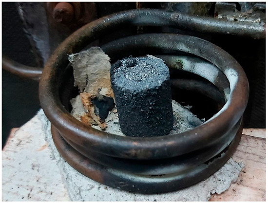
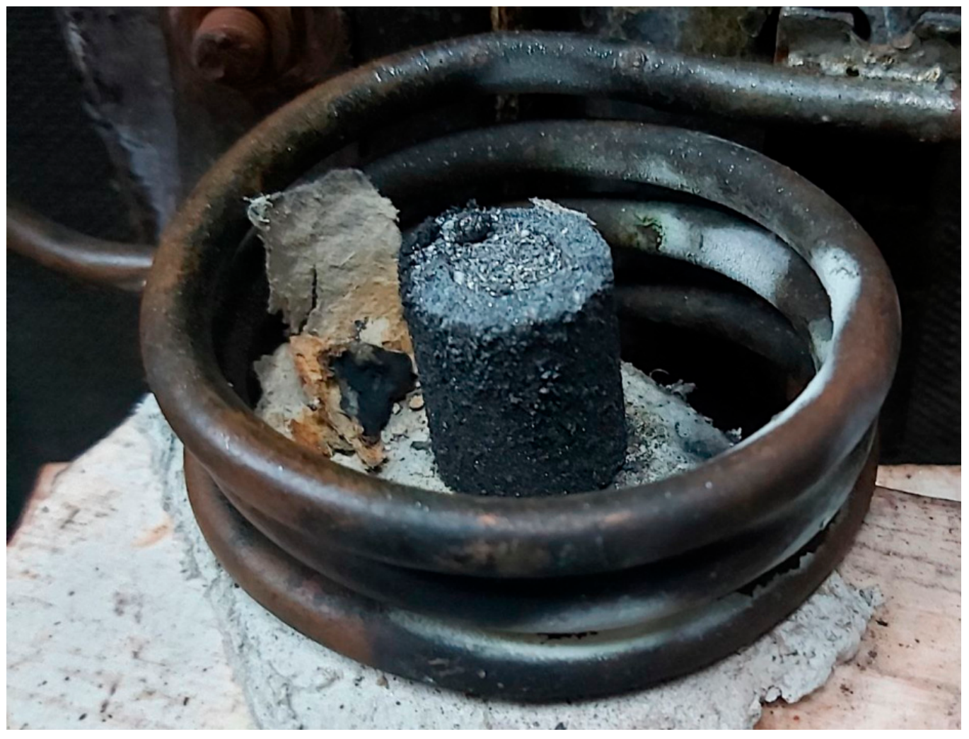
A VCHG-60/0.44 high-frequency tube generator (Beijing Jingyi Precision Machinery Co., Ltd., Beijing, China) was used to heat the charge-filled crucible. Melting was performed within the inductor (Figure 1). The melting temperature was estimated by an infrared pyrometer and was approximately 1600 °C.
Figure 1.
Melting the charge in the graphite crucible.
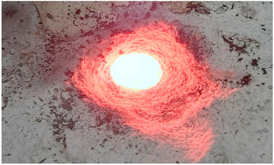
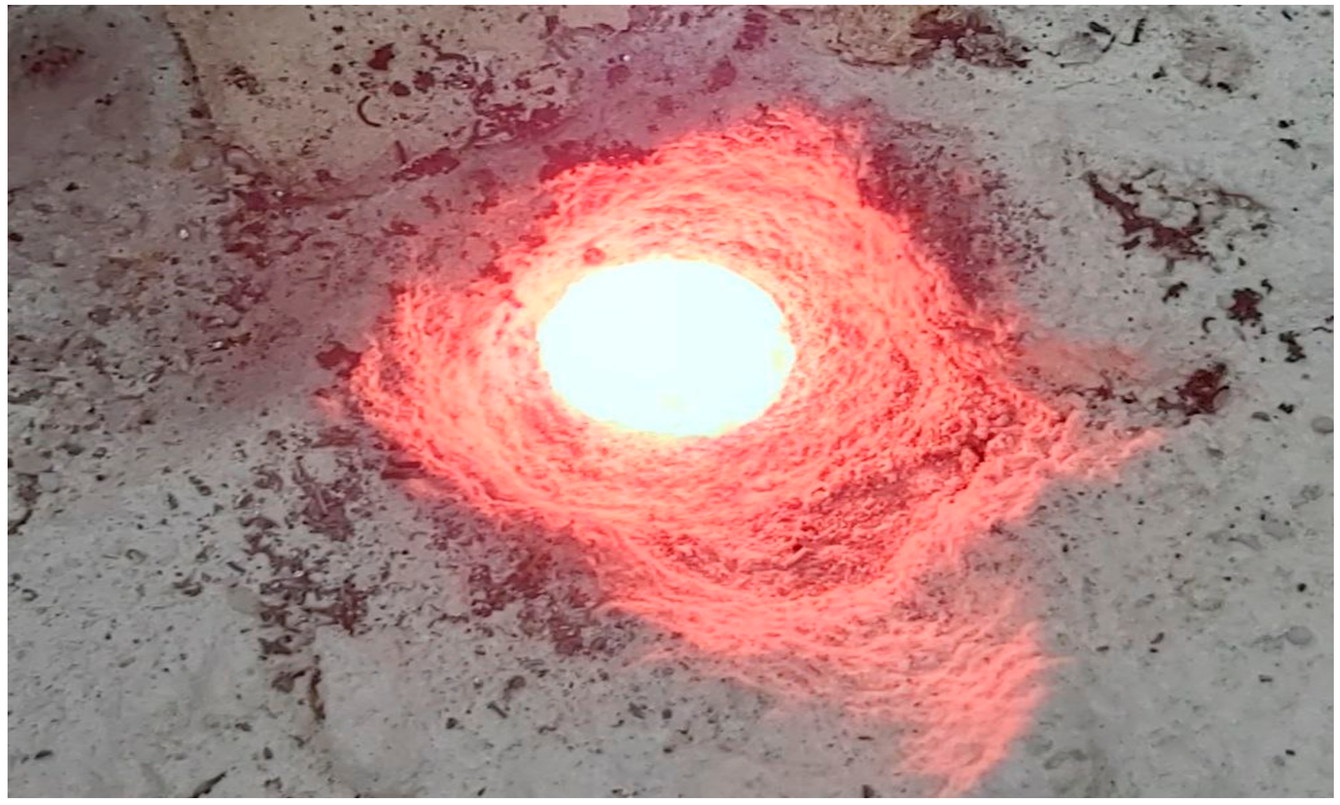
Subsequently, the melt was poured from the crucible into a refractory mold (Figure 2).
Figure 2.
Molten charge.
The samples were cast in the shape of ø10 mm diameter, 60 mm high cylinders. Two high-boron-content samples were annealed at 1100 °C for 6 h, followed by slow furnace cooling.
2.2. Siliconizing Materials
The following materials were used in the siliconizing process:
- Metal samples from the experimental alloy;
- Silicon powder;
- Activator: ammonium chloride (NH4Cl);
- Mortar (refractory mortar): finely ground refractory mixture designed for bonding refractory products in masonry and for filling joints, typically after the addition of water.
2.3. Siliconizing Method
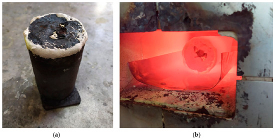
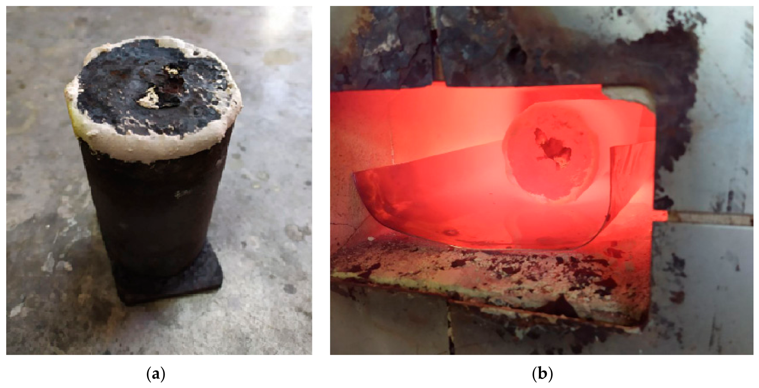
For siliconizing, the test samples were placed in a small container filled with silicon powder (Figure 3a) to prevent external gases from entering the furnace. The assembled container was placed in a tray and loaded into the chamber furnace (Figure 3b).
Figure 3.
Siliconizing process: (a) large container with samples; (b) container in the furnace.
2.4. Elemental Analysis
We used the SPECTROLAB LAVM 11 (SPECTRO Analytical Instruments GmbH, Kleve, Germany) device to determine the elements in the obtained samples.
2.5. Metallographic Examination
For metallographic examination, a cross-section was prepared from samples using standard metallographic procedures. The samples were small cylinders with diameters up to 10 mm and heights up to 20 mm. First, the surface was ground using a water-cooled abrasive wheel (CORMAK M300S (CORMAK, Biała Podlaska, Poland)), followed by sequential manual sanding using waterproof sandpaper with grit sizes ranging from P100 to P5000. The surface was then polished using a felt wheel with a water-based chromium oxide suspension (Bainpol-VT (Chennai Metco Pvt. Ltd., Chennai, India)), rinsed and dried. Etching was carried out using the standard method in a 4% nitric acid solution in ethyl alcohol. To observe and record the microstructure, a metallographic microscope, “ZEISS AXIO Vert. A1” (Axio Vert.A1; Carl Zeiss Microscopy GmbH, Jena, Germany), was used at different magnifications (from 50× to 1000×). The sizes of structural components were measured using the Digimizer 4.6.1 program.
2.6. Hardness and Microhardness Measurement
Hardness was measured using the TK-2M (HRC) device (Ivanovo plant of testing devices, Ivanovo, USSR). Microhardness was measured on the PMT-3 device (Tochpribor, Ivanovo, USSR) at a load of 100 g and 200 g; exposure time: 10 s.
2.7. X-Ray Diffraction (XRD) Analysis
X-ray diffraction (XRD) analysis was performed on a DRON-4 diffractometer (JSC IC Bourevestnik, St. Petersburg, USSR) using digital data acquisition and copper radiation. The diffraction patterns were analyzed using the Match! 4 software.
3. Results
3.1. Study of Boron Addition to Cr7Mm3Ni2SiB Multi-Element Alloy
3.1.1. Elemental Composition of the Obtained Melts
Several experimental melts were obtained, which differed mainly in the amount of boron-containing substance added to the charge. In this case, it should be noted that the proportional ratio of the amount of boron-containing substance and flux was maintained in all experimental melts.
After elemental analysis, the following elemental composition of the samples was obtained (see Table 4).
Table 4.
Elemental composition of the samples.
According to Table 4, after annealing, the amounts of carbon and boron decreased slightly because these elements have high diffusivity; therefore, decarburization and deboronization occurred. The levels of harmful impurities, sulfur and phosphorus decreased with increasing boron content in the melt, indicating the refining effect of boron. The mechanism of refining action can be explained using the example of sulfur. Boron forms a low-melting sulfide, B2S3, with sulfur, which sublimes at 250 °C. Since boron is a surface-active element, it actively displaces harmful impurities during melting; therefore, a decrease in sulfur and phosphorus is observed.
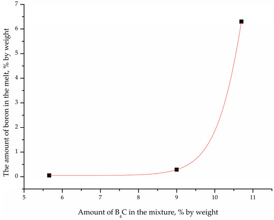
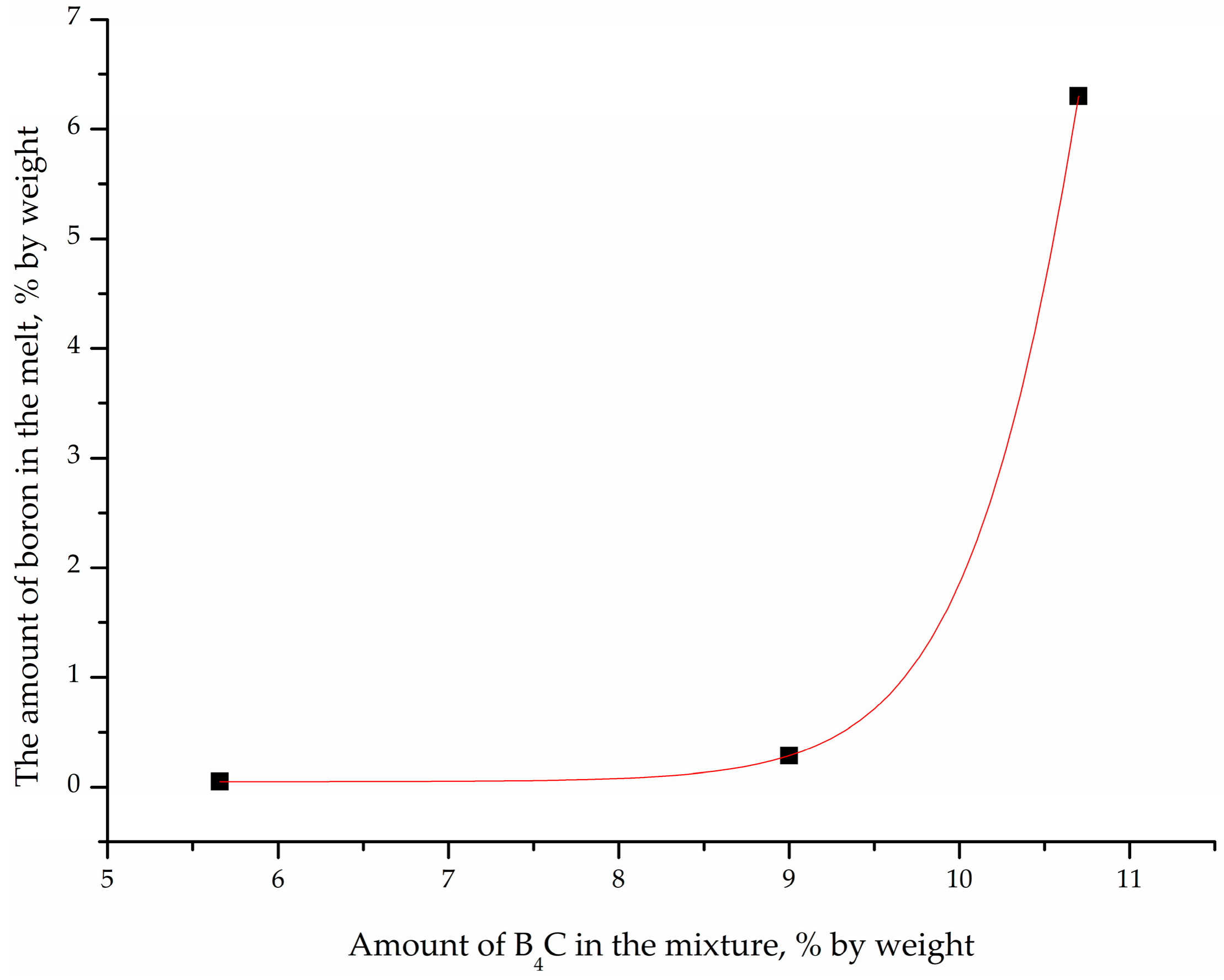
Thanks to elemental analysis, the amount of boron in each melt was determined. Therefore, knowing the boron-containing substance levels for each charge as well as the amount of boron in the melt (Table 3 and Table 4), it was possible to construct a graph (Figure 4).
Figure 4.
Dependence of the amount of boron-containing substance in the charge on the amount of boron in the melt.
From the graph, it can be concluded that a non-linear increase is observed. This means that the growth rate of boron in the melt is proportional to the value of the amount of boron-containing substance itself in the charge.
3.1.2. Metallographic Examinations
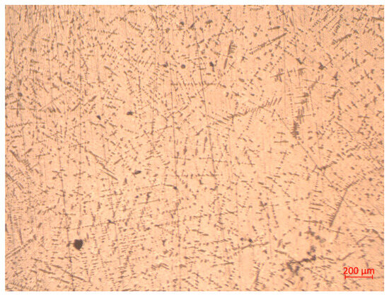
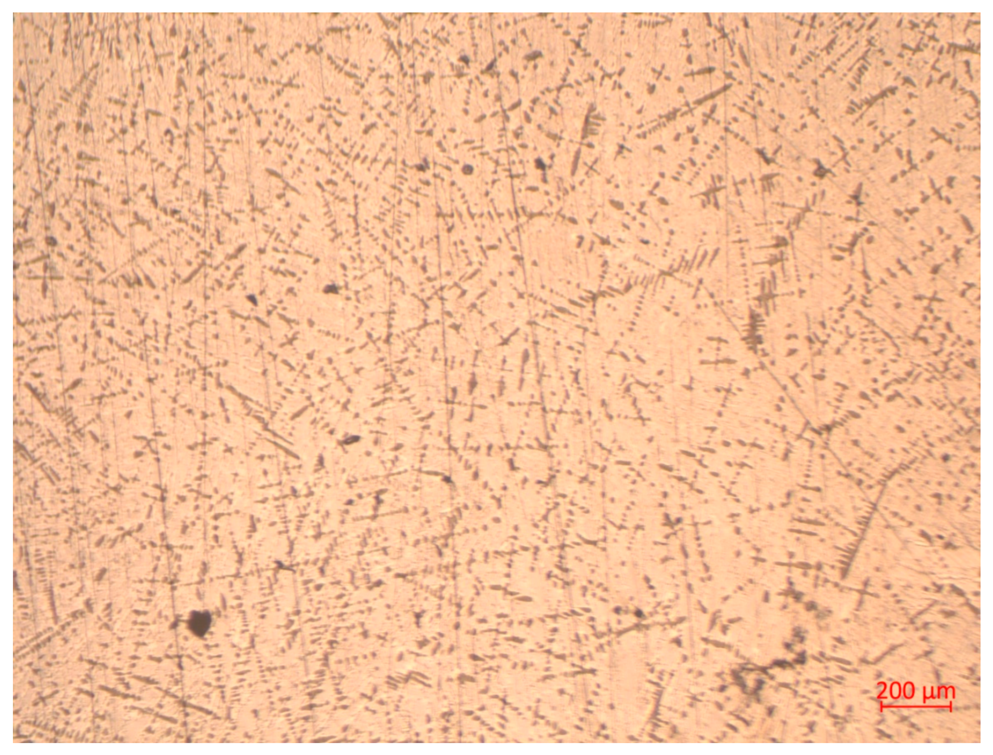
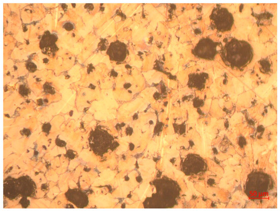
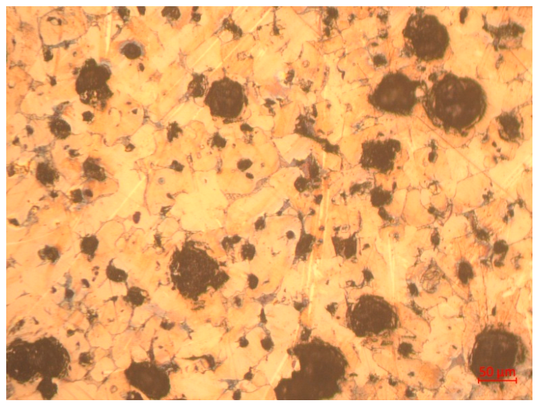
Metallographic examinations of the first sample (150 g of metal shavings + 15 g (B4C + NaF)) and 0.05% boron showed that its overall structure consists of dendrites, primary pearlite-type crystals, and eutectics (Figure 5).
Figure 5.
General view of the structure of sample No. 1 (×50).
The obtained structure is closer to that of conventional steels during primary crystallization because a minimum amount of boron was introduced into the alloy, resulting in a minimal effect on structural changes.
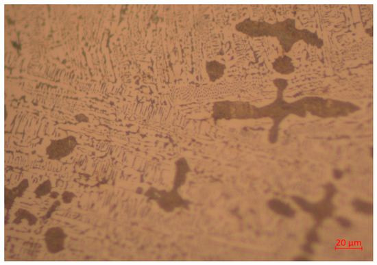
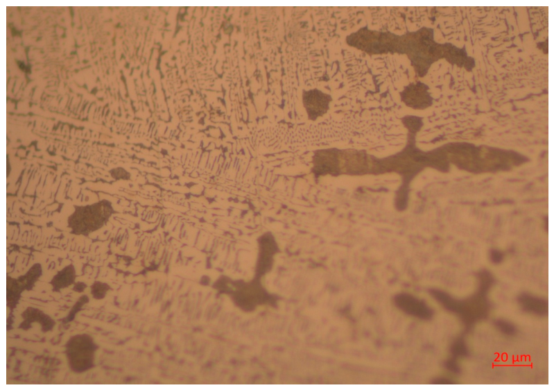
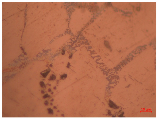
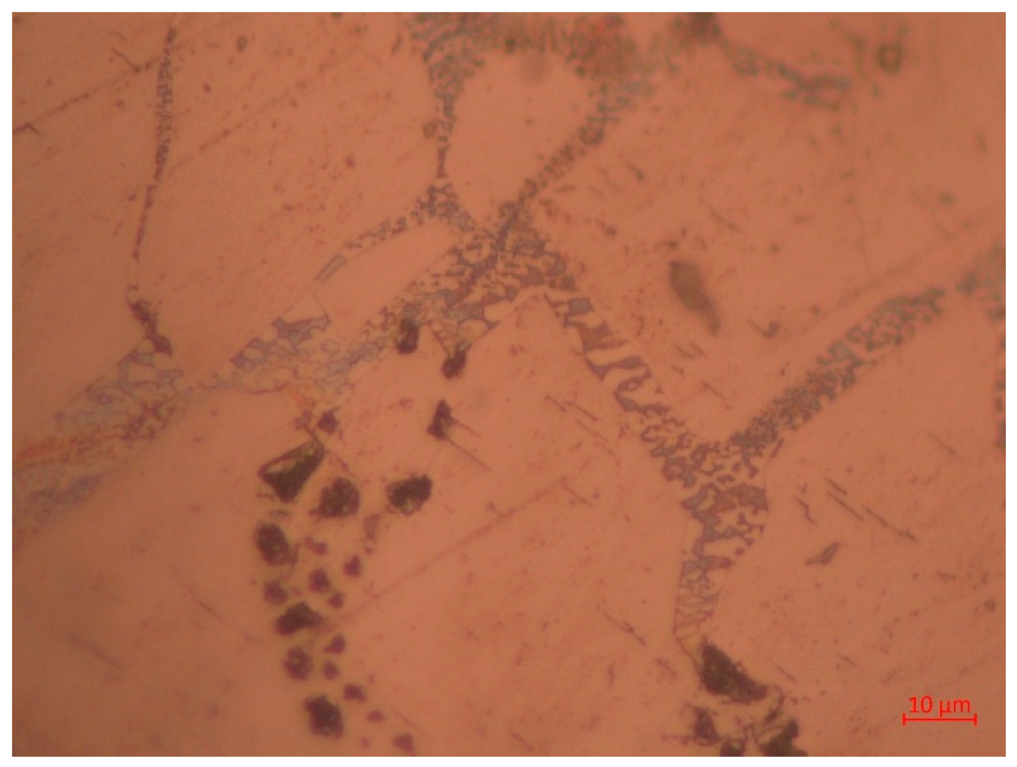
When enlarging the image, it is seen that, compared to the second sample with a thin eutectic, the eutectic in the first sample is more irregular (Figure 6).
Figure 6.
Eutectic in the first sample (×500).
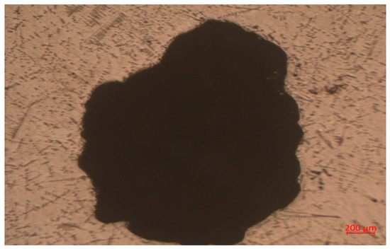
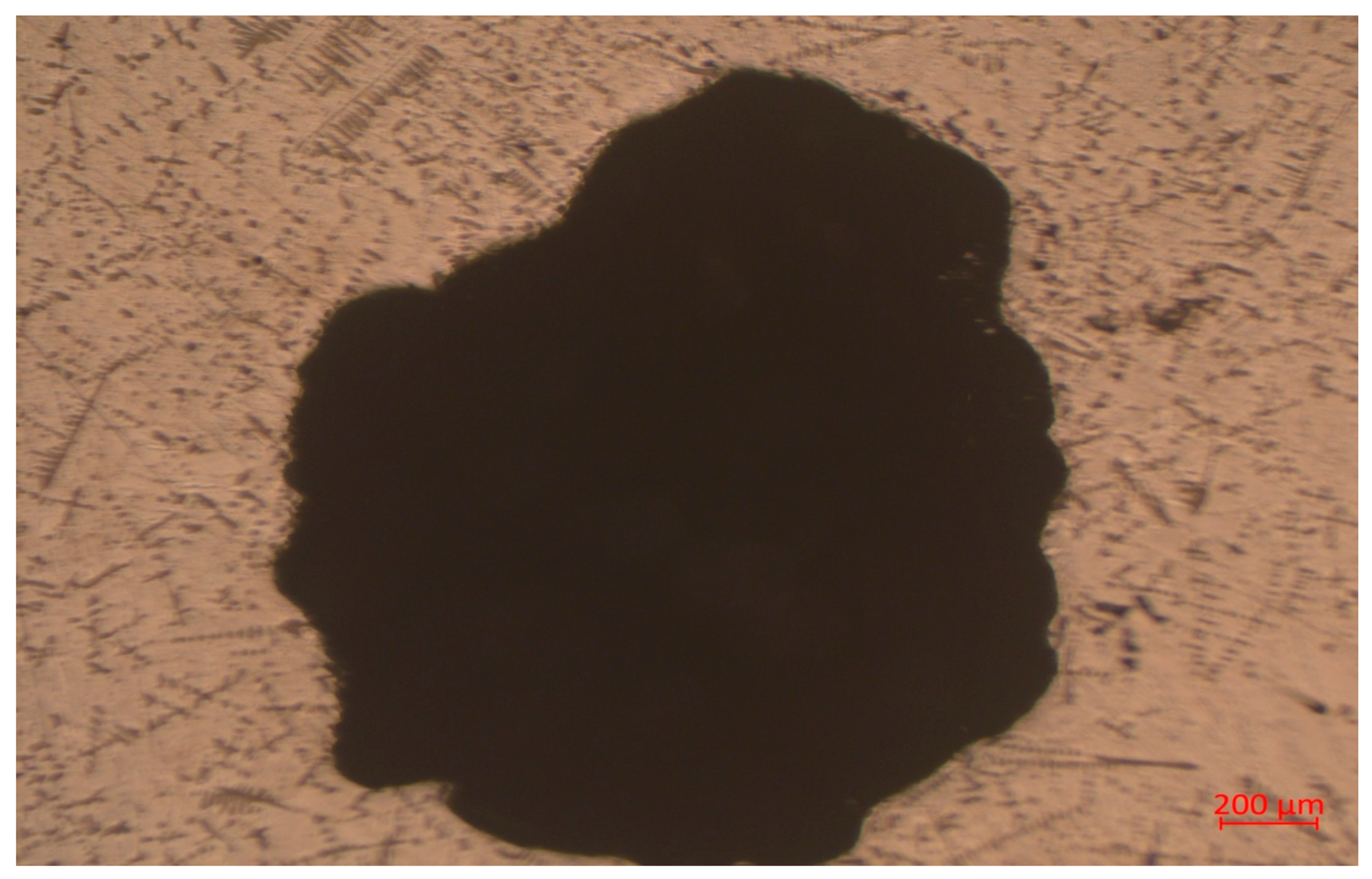
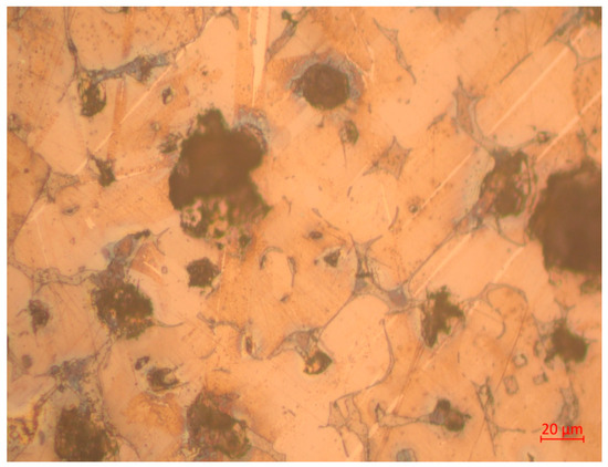
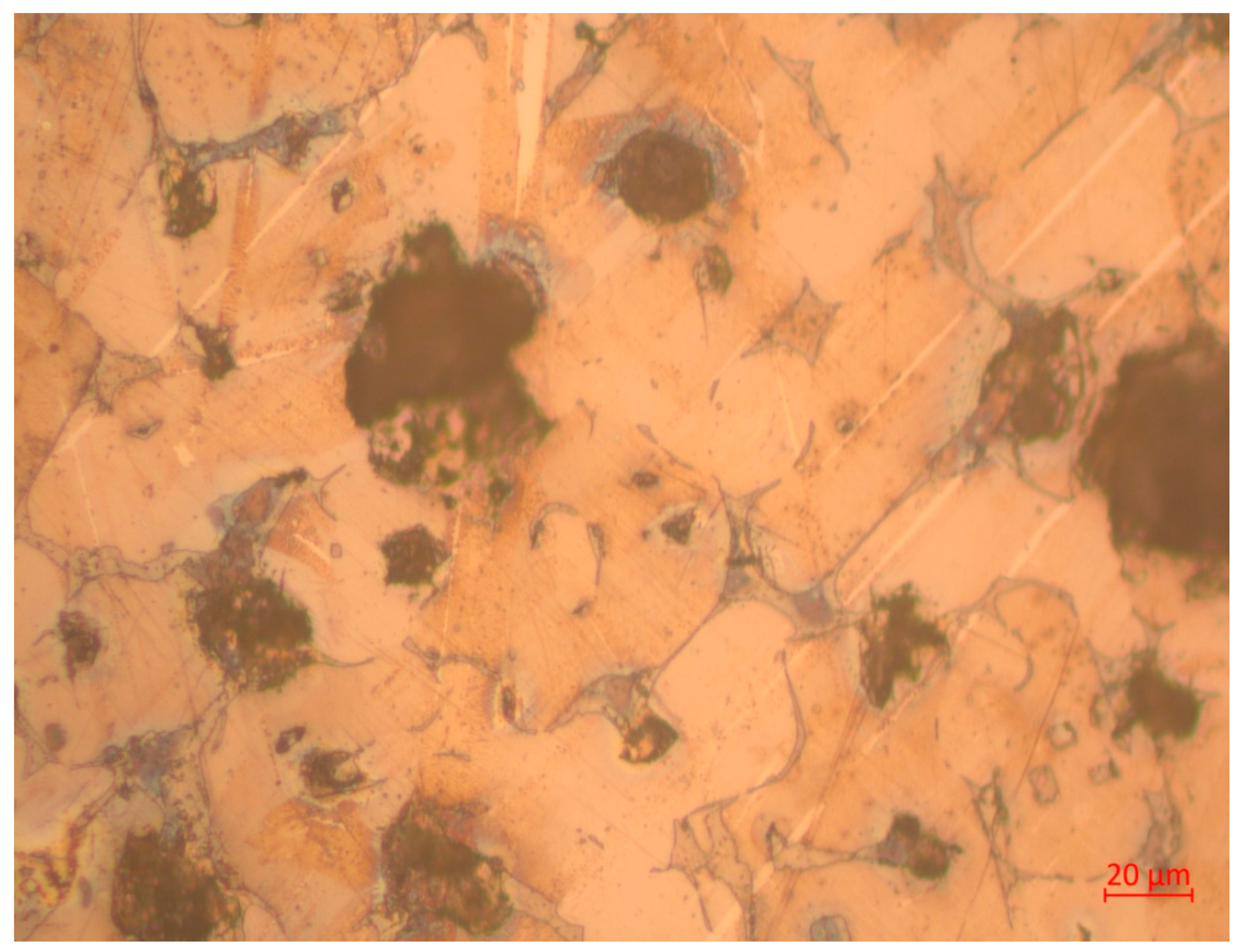
Also, during the second sample study, a pore was detected in the structure, a characteristic defect in castings of this composition. An example of such a defect is shown in Figure 7.
Figure 7.
Pore in sample No. 1 (×50).
Thus, during crystallization, heterogeneous phase growth and possible porosity are realized, which significantly limit the use of the alloy composition in melt No. 1 for practical applications.
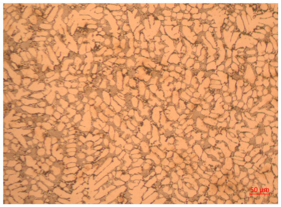
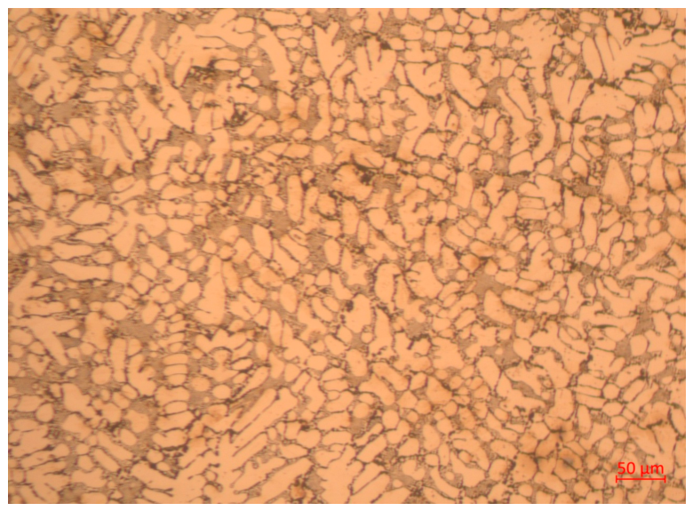
As a result of melting the charge of composition No. 2, 100 g of metal shavings + 15 g (B4C + NaF), a sample of primary crystallization was obtained, the general structure of which is shown in Figure 8.
Figure 8.
The general structure of sample No. 2 after the primary crystallization (×200).
According to the image in Figure 8, it is possible to distinguish 3 structural components conditionally. The first is clearly defined grains, which are similar in shape to dendrites; however, because boron reduced the interfacial surface energy, the grains assumed a more rounded shape. The average grain size is 20.71 μm. The second structural component is black inclusions located along the grain boundaries. Presumably, these black inclusions are boron segregations. The average segregation size is 5.77 μm. The third component is the eutectic, observed between the grains. The average size of the eutectic plates is 2.73 μm.
Thus, as a result of melting from charge No. 2, a high-quality sample without pores and a more optimal microstructure were obtained as compared to the first case. The main structural components have a fairly fine, rounded shape; the eutectic component occupies a small microvolume and has very dispersed phase components.
After annealing at 1100 °C for 6 h, followed by cooling with a furnace to 300 °C for 15 h, the sample with the composition of charge No. 2 had the following general structure (Figure 9).
Figure 9.
Microstructure of melt No. 2 after annealing (×100).
Figure 9 shows that the eutectic morphology changed somewhat.
As a result of melting the charge of composition No. 3, 50 g of metal shavings + 10 g (B4C + NaF), we obtained a sample of primary crystallization, the general structure of which is shown in Figure 10.
Figure 10.
General view of the structure of sample No. 3 (×50).
From Figure 10, it is clear that many boron carbide particles in the alloy did not have time to react, so we can conclude that we reached the limit content of the boride component, and its further increase is unnecessary.
If you enlarge the image of the structure, you can see that there are grains and there are interlayers of another phase between the main matrix phase (Figure 11).
Figure 11.
Interlayers between the main matrix phase (×500).
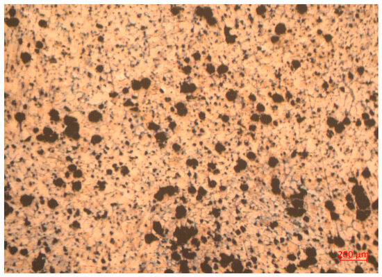
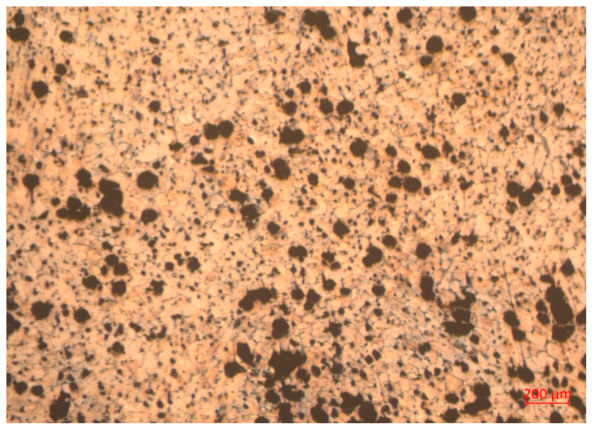
Annealing at 1100 °C results in only minor changes in the microstructure (Figure 12).
Figure 12.
Microstructure of sample No. 3 after annealing (×200).
The microstructure of sample No. 3 resembles the microstructure of high-strength cast iron.
3.1.3. Mechanical Properties
Hardness measurements, tensile tests, and impact toughness testing were performed on three samples after primary crystallization with different composition of the charge: the first sample—150 g of metal shavings + 15 g (B4C + NaF); the second sample—100 g of metal shavings + 15 g (B4C + NaF); the third sample—50 g of metal shavings + 10 g (B4C + NaF) (Table 5).
Table 5.
Mechanical properties.
As shown in Table 5, the primary crystallized samples after casting have a fairly high hardness, approximately equal to that of hardened tool steels. After annealing, the hardness of the samples decreases but remains quite high. This is evidence that the obtained structures are quite stable even at 1100 °C for 6 h. At the same time, the decrease in hardness during annealing improves the alloys’ ductility.
On sample No. 2, after primary crystallization, the microhardness of the structural components was measured (at a load of 100 g). The microhardness of clearly defined grains is 7390 MPa, the eutectic has a microhardness of 4430 MPa, and the microhardness of the dark region is 2730 MPa.
The microhardness of the first sample was measured at a load of 200 g. The following results were obtained: the microhardness of the eutectic is 8860 MPa, and the microhardness of the dendrites is 6750 MPa. In the first sample, the eutectic has a higher micro-hardness than the dendrites. In the second sample, the grains, in contrast, have a higher microhardness than the eutectic structure.
The microhardness of sample No. 3 after annealing was measured on two structural components at a load of 200 g. The first component is the matrix phase, with a microhardness of 14,180 MPa, and the second is the phase between the grains, with a microhardness of 6050 MPa. Judging by the microhardness, we can conclude that the phase between the grains is a solid solution of boron in the alloy, and the grains themselves are Fe2B boride.
To compare the obtained microhardness measurement results, all data are presented in Table 6.
Table 6.
Microhardness measurement results.
Static strength indicators in all samples are high, except for melt No. 1. Melt No. 1 has a dendritic morphology of primary crystallization, which causes relatively low indicators of strength, ductility, and impact toughness. The dispersed eutectic morphology of the structure in melt No. 2 and the uniform spherical inclusions in melt No. 3 provide a high combination of properties. We see the preservation of high strength together with a combination of good indicators of ductility and impact toughness.
3.2. Research of Porous Silicide-Nitrogen Coating
3.2.1. Results of Siliconizing with Simultaneous Nitrogen Saturation
To create a protective barrier, the siliconizing technology with simultaneous nitrogen saturation was tested on the experimental melts obtained. Saturation was carried out in a container for 1.5 h at 900 °C, with subsequent slow cooling in a furnace at a rate of approximately 0.08 deg./s.
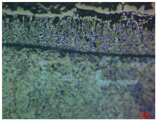
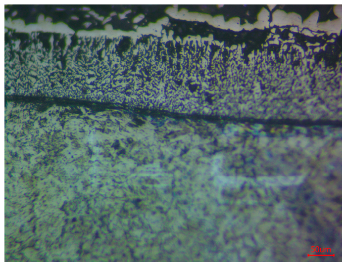
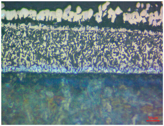
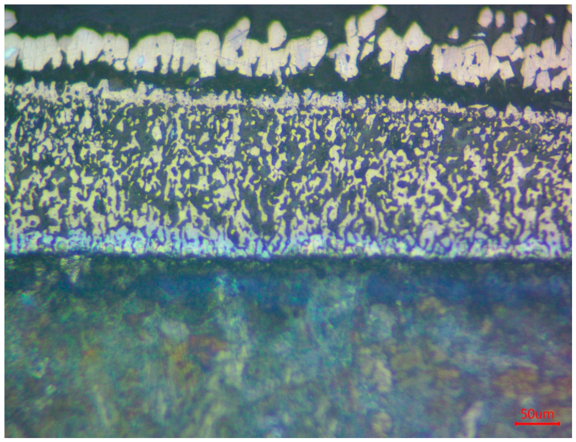
Metallographic analysis of the cross-section confirmed the presence of a formed layer (Figure 13).
Figure 13.
General view of the microstructure of the siliconized layer obtained at a temperature of 900 °C (×200).
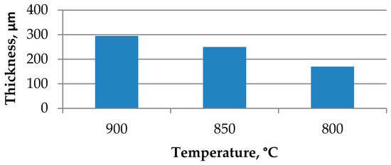
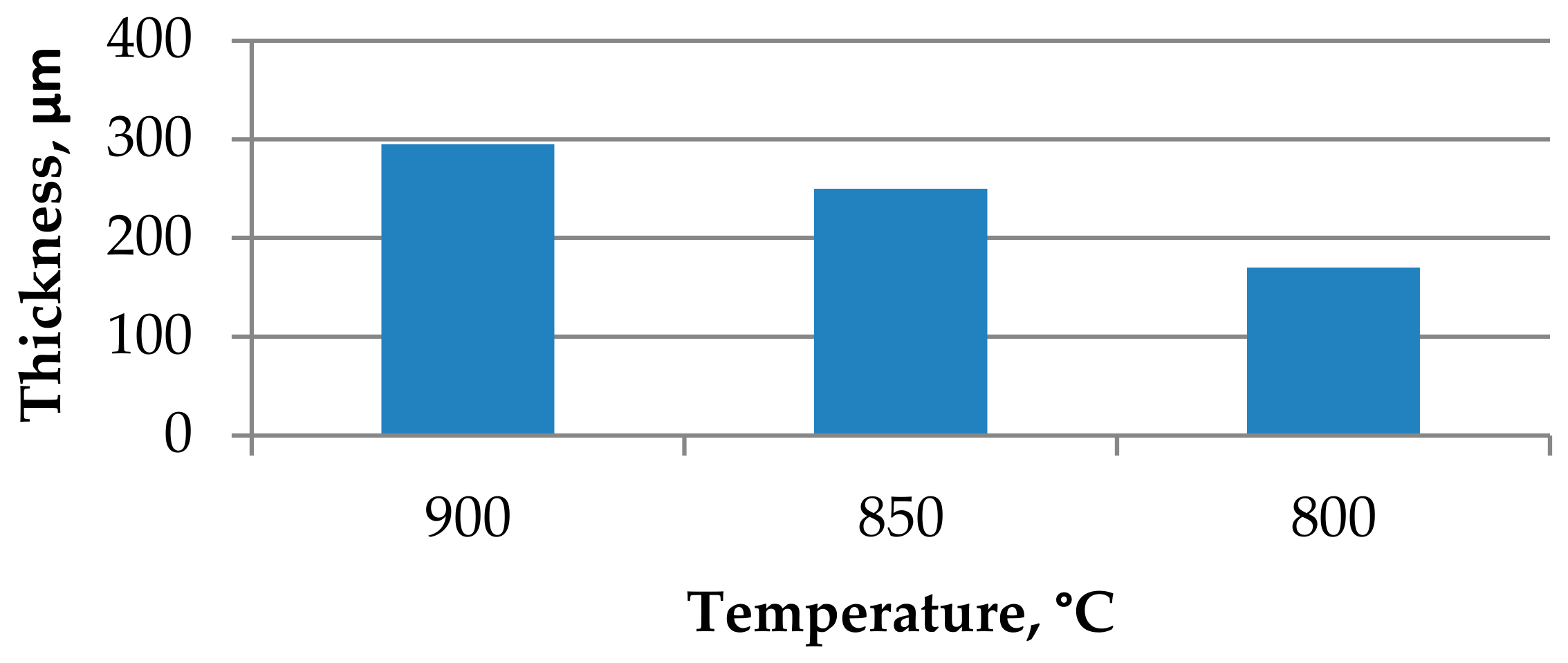
During the research, it was found that after the treatment, a two-layer silicide layer with a total thickness of approximately 295 μm formed on the surface, as observed under microscopic analysis. The outer layer has a thickness of about 173 μm and is characterized by an uneven, porous sintered silicon structure. The inner part of the layer is about 111 μm. It has a light color but a denser structure, with fewer pores. The reduced porosity is due to the formation of dense compounds and the participation of nitrogen and oxygen.
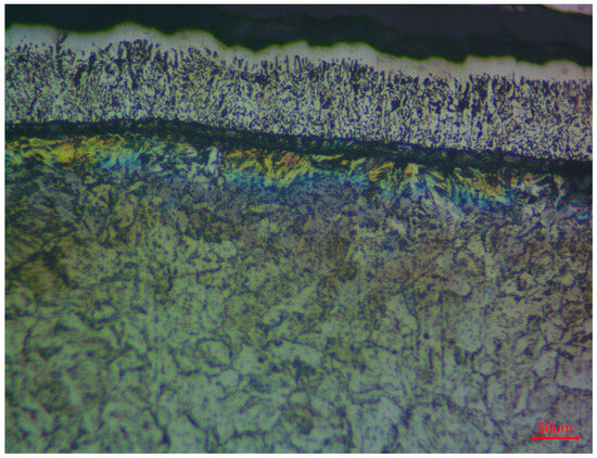
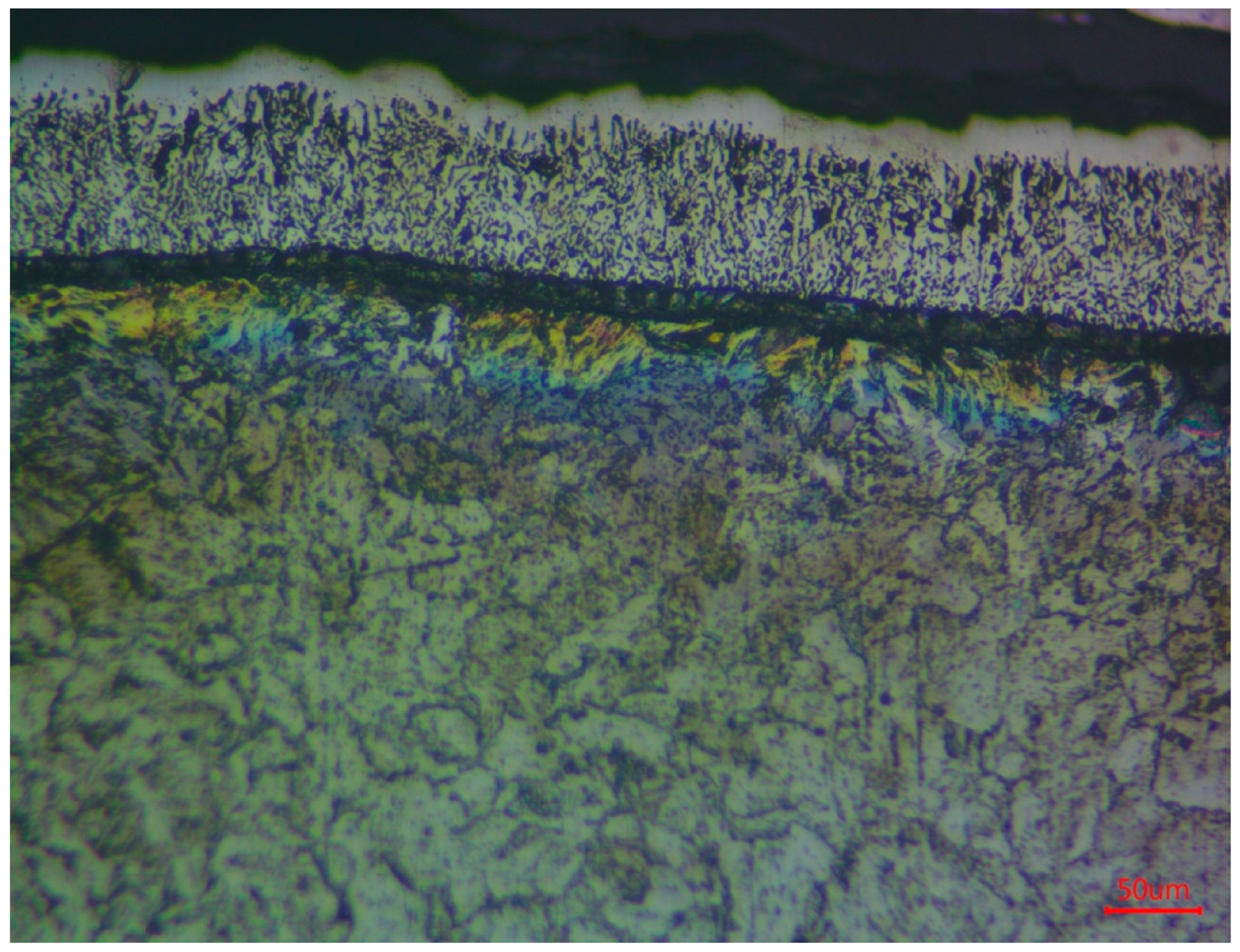
The transition zone with the pearlite component is saturated with carbon pressed from the surface and is 200 μm, which generally creates a structural gradient. If we do not consider the surface technological porous layer of sintered silicon (which can be removed by etching, grinding, and polishing), the total thickness of the hardened surface zone is at least 300 μm. After siliconizing at 850 °C for 1.5 h, the layer structure shown in Figure 14 was obtained. A two-layer silicide layer with a total thickness of approximately 250 μm was formed on the surface. When siliconizing at 800 °C for 1.5 h, the layer structure shown in Figure 15 was obtained. A two-layer silicide layer with a total thickness of approximately 170 μm was formed on the surface.
Figure 14.
Silicide layer and transition zone after treatment at 850 °C (×200).
Figure 15.
Silicide layer and transition zone after treatment at 800 °C (×200).
Thus, the dependence of the temperature change on the thickness of the silicified layer can be traced (Figure 16).
Figure 16.
Diagram of the dependence of the thickness of the silicide layer on temperature.
3.2.2. X-Ray Diffraction Analysis of Silicide Coatings
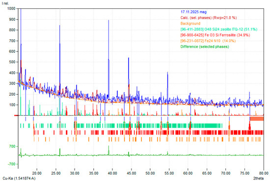
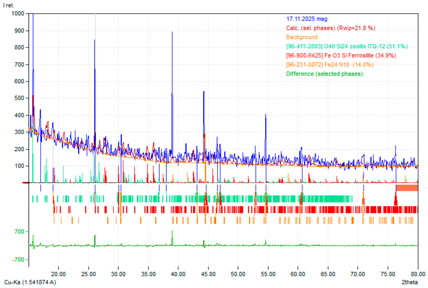
Phase analysis was performed for high-power samples. Figure 17 shows a typical diffraction pattern of a sample after siliconizing.
Figure 17.
Diffraction pattern of a reinforced coating sample.
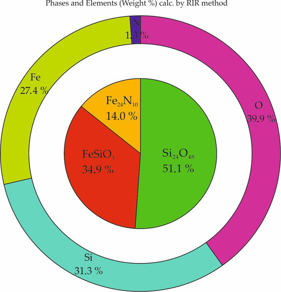
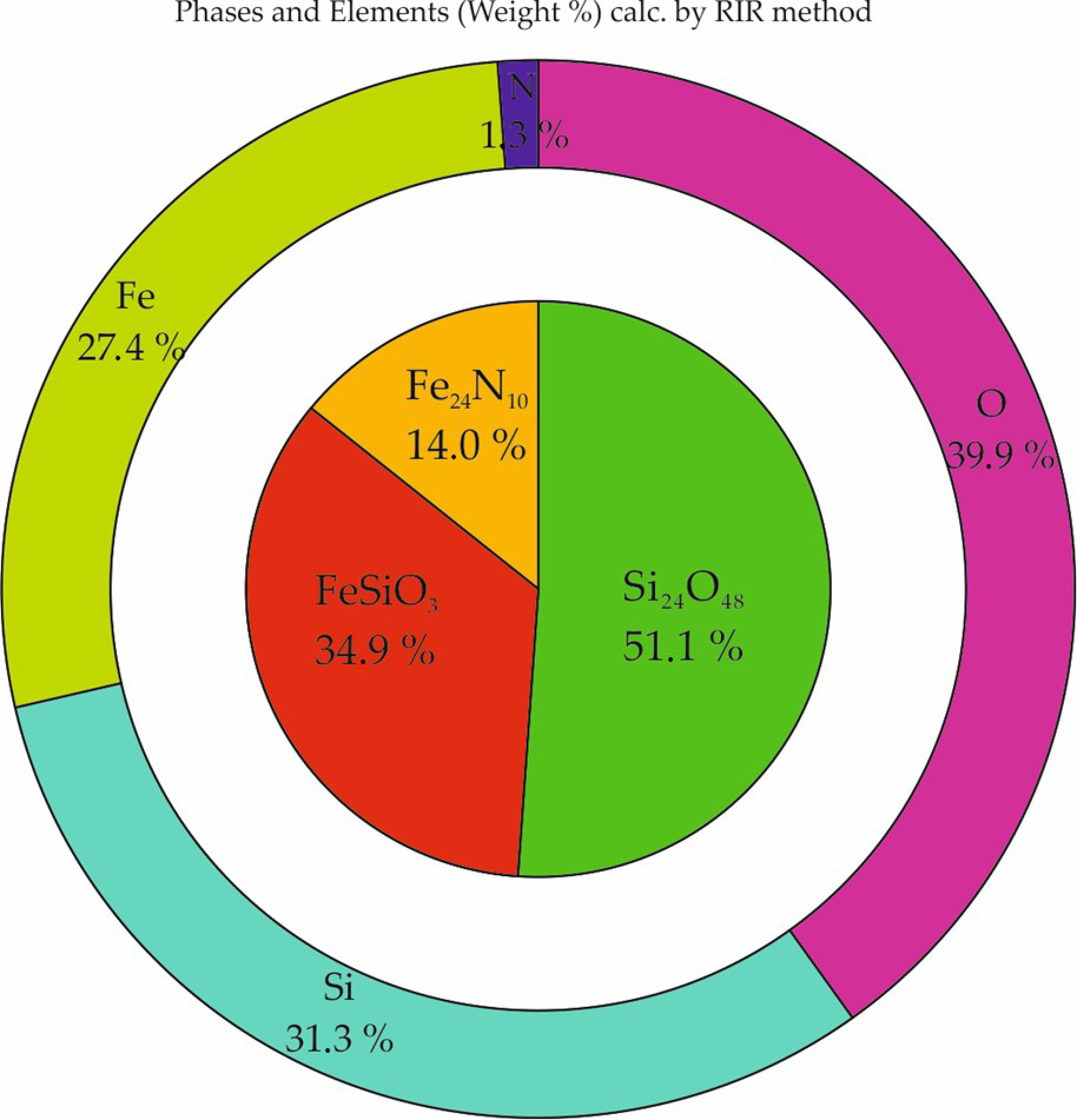
Figure 18 shows the phase and elemental composition diagram, and Table 7 lists their values. The decoding data were obtained using Mach!4 software (Crystal Impact, Dr. H. Putz and Dr. K. Brandenburg GbR, Bonn, Germany) [86].
Figure 18.
Phase and elemental composition diagram of a reinforced coating sample.
Table 7.
Phase and elemental composition of the sample after siliconizing.
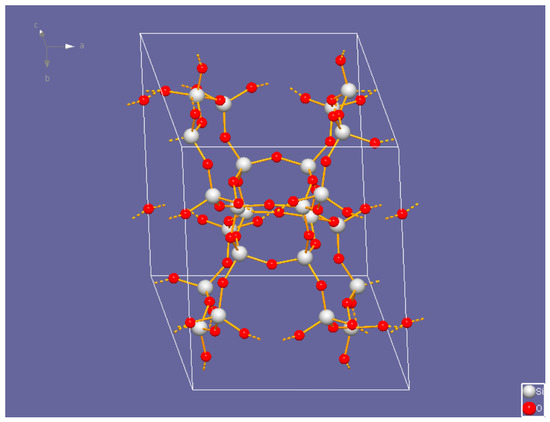
Si24O48 is a zeolite [87]. Space group C1m1: crystal system is monoclinic. Cell parameters: a = 10.3360 Å, b = 15.0177 Å, c = 8.8639 Å, β = 105.356º. The theoretical density is 1.804 g/cm3. The three-dimensional model of the structure built in Diamond software (version 5, Crystal Impact, Dr. H. Putz and Dr. K. Brandenburg GbR, Bonn, Germany) is presented in Figure 19 [86].
Figure 19.
The three-dimensional model of the Si24O48 structure. Silicon and oxygen atoms are represented by grey and red spheres, respectively. Solid orange lines denote Si–O covalent bonds within the boundaries of the unit cell, while dashed orange lines represent bonds extending to adjacent cells, highlighting the continuous 3D-framework. The white wireframe indicates the unit cell volume.
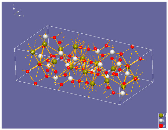
FeSiO3 is ferrosilite [88]. Space group Pbca: crystal system is orthorhombic. Cell parameters: a = 18.3700 Å, b = 9.0060 Å, c = 5.2084 Å. The theoretical density is 4.067 g/cm3. The three-dimensional model of the structure built in Diamond software [86] is presented in Figure 20.
Figure 20.
The three-dimensional model of the FeSiO3 structure. The atoms are color-coded as follows: iron (Fe) in olive, silicon (Si) in grey, and oxygen (O) in red. Solid orange lines show the primary coordination bonds within the unit cell, forming the characteristic silicate chains and metal-oxygen polyhedra. Dashed orange lines visualize the periodic boundary conditions, showing bonds that connect atoms to their counterparts in adjacent unit cells. The white wireframe outlines the simulation box/unit cell limits.
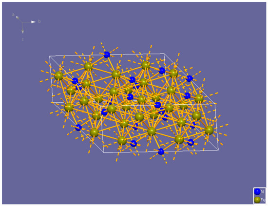
Fe24N10 is iron nitride [89]. Space group P312: crystal system is trigonal (hexagonal axes). Cell parameters: a = 9.2150 Å, c = 4.3440 Å. The theoretical density is 7.695 g/cm3. The three-dimensional model of the structure built in the Diamond program is presented in Figure 21.
Figure 21.
The three-dimensional model of the Fe24N10 structure. Iron (Fe) atoms are indicated by olive spheres, and nitrogen (N) atoms are shown as blue spheres. Solid orange lines represent the interatomic bonds within the unit cell, while dashed orange lines denote boundary bonds connecting to atoms in adjacent cells, illustrating the periodic nature of the crystal lattice. The white wireframe box defines the unit cell volume.
Such models are a step toward predicting the properties of individual phases using neural networks.
We can see that the basis consists of oxide-silicide, iron-silicide-oxide, and nitride phases, which serve as ready-made barrier layers to counteract high-temperature oxidation. Previous experiments with oxidation at 1000 °C for 8 h showed no change in sample mass within 0.001 g. Mass gain begins during tests at 1100 °C and amounts to only 0.003 g.
4. Discussion and Main Limitations of This Research
According to the results of experiments on induction melting and thermal diffusion saturation of the surface, we have a complex “base material–barrier coating”. The base material is formed from available elements and has high hardness and thermal stability (it is resistant to high-temperature annealing while maintaining high hardness).
The surface layer consists of silicide-oxide and nitride phases that are resistant to high-temperature oxidation, providing a close match in hardness to the base material. When forming a layer saturated with silicon and nitrogen, the temperature can be varied without causing noticeable collective recrystallisation or deterioration of the mechanical characteristics of the base material.
Preliminary wear tests to determine the friction coefficient have shown that additionally deposited copper silicided surfaces with subsequent annealing have a high level of wear resistance under dry friction conditions, which corresponds to the operating conditions of electrical contactors, and have a relatively low friction coefficient of 0.19, which is somewhat better than when rubbing a copper/carbon composite [46]. Of course, scale and wear resistance properties, as well as the development of mold-filling technology, require further detailed study. However, the porosity of the silicified coating is a convenient container for filling with a functional structural component that will dictate the material’s application range. For example, by filling the coating’s pores with copper, it is possible to increase electrical conductivity and reduce the friction coefficient, allowing the use of such a material in electric vehicle contactors. By filling the pores with a different filler to increase the friction coefficient and by using a thermally stable base, as in the alloys proposed above, this material can be used in braking systems. The main thesis here is the universality of the approach to obtaining materials with radically different properties without significantly complicating technologies or reducing the range of equipment and quality control methods. Such an approach creates good prerequisites for the stable innovative development of enterprises, minimizing risks when investing in the implementation of new developments in real production.
The proposed base material–barrier coating systems align with the strategic goals of sustainable railway transport development. It can be assumed that, thanks to significant improvements in mechanical performance, the service life of key components will increase, helping reduce resource consumption and the frequency of maintenance. Of course, for practical implementation in the real-world engineering sector, operational testing involving an analysis of wear at high temperatures is required.
5. Conclusions
Analysis of the obtained experimental test results allows us to draw the following main conclusions.
1. Utilizing advanced porous metal alloys and multi-material systems in railway infrastructure represents a sustainable engineering solution that achieves significant weight savings, enhanced heat flow, and more reliable operations.
2. It was found that the formation of a multi-phase silicide layer (FeSi, Si2CN4) provides a synergistic effect, doubling surface hardness and creating a stable SiO2 diffusion barrier at 1000–1200 °C. This mechanism ensures high adhesion and wear resistance, offering a resource-efficient and cost-effective alternative to conventional barrier coatings for high-temperature industrial environments.
3. It was found that when melting a charge with different contents of boron-containing substances, we obtained alloys with a high boron content and a different structure, which nonetheless had a sufficiently high hardness in the initial state, which provided sufficiently high strength and heat resistance. The presence of the Fe2B phase in the structure accounts for the high hardness.
4. Elemental analysis showed that the samples have different boron contents: the more boron, the less sulfur and phosphorus, that is, the alloy is purified of harmful impurities.
5. It was established that the dependence of boron on boron-containing substances is subject to exponential dependence, that is, it is possible to determine how much boron-containing substance should be given to approximately predict what boron concentrations can be achieved.
6. It was established, based on the results of measurements of the microhardness of individual structural components, that in a multi-element system, there is a formation of a solid solution based on iron with high microhardness, which is not characteristic of a conventional solid solution of boron in iron.
7. At a sufficiently high concentration of boron, structures are formed that resemble the morphology of the structures of high-strength cast irons.
8. The proposed composition of the mixture for saturation with silicon and nitrogen allows reducing the processing time from 5 h, which was used in previous experiments, to 1.5 h, considering the warm-up time. That is, the holding time is reduced 3.3 times; compared with traditional siliconizing, it is reduced 5.3 times.
9. The obtained layer thicknesses show that, in terms of parameters, they are not inferior to layers obtained by traditional silicification for 8 h.
10. X-ray diffraction analysis revealed the phase composition of the layers, showing that in the case of steel, oxy-silicide and nitride phases are formed. This can serve as an effective barrier layer against high-temperature oxidation.
11. The pores in the siliconized layer are containers for a functional filler and, according to preliminary data, can serve as a flexible and versatile toolkit for creating parts for a specific purpose. Such parts can be contactors with high conductivity and a relatively low coefficient of friction if the pores are filled with copper.
Author Contributions
Conceptualization, S.K.; methodology, S.K. and H.K.; software, S.K. and H.K.; validation, B.T. and H.K.; formal analysis, H.K. and M.B.; investigation, S.K. and H.K.; resources, S.K.; data curation, L.N. and B.T.; writing—original draft preparation, S.K.; writing—review and editing, S.K., M.G., H.K., B.T. and L.N.; visualization, S.K.; supervision, H.K., B.T. and M.G.; project administration, B.T.; funding acquisition, M.G. and LN. All authors have read and agreed to the published version of the manuscript.
Funding
This research received no external funding.
Institutional Review Board Statement
Not applicable.
Informed Consent Statement
Not applicable.
Data Availability Statement
The original contributions presented in this study are included in the article. Further inquiries can be directed to the corresponding authors.
Acknowledgments
We express our gratitude to the authors of the Match!4 and Diamond 5 software, Klaus Brandenburg and Holger Putz, for providing a license.
Conflicts of Interest
Author Bohdan Trembach was employed by the company Private Joint Stock Company. The remaining authors declare that the research was conducted in the absence of any commercial or financial relationships that could be construed as a potential conflict of interest.
Abbreviations
| FCC | Face-centered cubic lattice |
| BCC | Body-centered cubic lattice |
| SEM | Scanning electron microscopy |
| HCP | Hexagonal Close-Packed |
| TEM | Transmission Electron Microscopy |
| XRD | X-ray diffraction |
References
- Letz, S.A.; Zhao, D.; März, M. Mesostructural impact on the macroscopic stress state and yield locus of porous polycrystalline silver. Mater. Des. 2022, 219, 110785. [Google Scholar] [CrossRef] [Scilit]
- Lefebvre, L.P.; Banhart, J.; Dunand, D.C. Porous metals and metallic foams: Current status and recent developments. Adv. Eng. Mater. 2008, 10, 775–787. [Google Scholar] [CrossRef] [Scilit]
- Alves, A.C.; Sendão, I.; Ariza, E.; Toptan, F.; Ponthiaux, P.; Pinto, A.M.P. Corrosion behaviour of porous Ti intended for biomedical applications. J. Porous Mater. 2016, 23, 1261–1268. [Google Scholar] [CrossRef] [Scilit]
- Rodriguez-Contreras, A.; Punset, M.; Calero, J.A.; Gil, F.J.; Ruperez, E.; Manero, J.M. Powder metallurgy with space holder for porous titanium implants: A review. J. Mater. Sci. Technol. 2021, 76, 129–149. [Google Scholar] [CrossRef] [Scilit]
- Zhang, B.; Yang, K.; Shen, L.; Duan, X.; Zhao, S.; Gao, W.; Xu, C.; Wang, J. Development, exploration and optimization of porous titanium and titanium alloys: A review. J. Sci. Adv. Mater. Devices 2025, 10, 100863. [Google Scholar] [CrossRef] [Scilit]
- Sawczuk, W.; Jüngst, M.; Ulbrich, D.; Kowalczyk, J. Modeling the depth of surface cracks in brake disc. Materials 2021, 14, 3890. [Google Scholar] [CrossRef] [Scilit] [PubMed]
- Ulbrich, D.; Kowalczyk, J.; Stachowiak, A.; Sawczuk, W.; Selech, J. The influence of surface preparation of the steel during the renovation of the car body on its corrosion resistance. Coatings 2021, 11, 384. [Google Scholar] [CrossRef] [Scilit]
- Babyak, M.; Keršys, R.; Neduzha, L. Improving the dependability evaluation technique of a transport vehicle. In Proceedings of the 24th International Scientific Conference Transport Means, Kaunas, Lithuania, 30 September–2 October 2020; pp. 646–651. [Google Scholar]
- Zhao, Y. Porous metals: Preparation, microstructure, properties and performance. Materials 2025, 18, 5518. [Google Scholar] [CrossRef] [Scilit]
- Nakajima, H. Fabrication, properties and application of porous metals with directional pores. Prog. Mater. Sci. 2007, 52, 1091–1173. [Google Scholar] [CrossRef] [Scilit]
- Myamlin, S.; Lunys, O.; Neduzha, L.; Kyryl’chuk, O. Mathematical modeling of dynamic loading of cassette bearings for freight cars. In Proceedings of the 21st International Scientific Conference Transport Means, Juodkrante, Lithuania, 20–22 September 2017; pp. 973–976. [Google Scholar]
- Myamlin, S.; Dailidka, S.; Neduzha, L. Mathematical modeling of a cargo locomotive. In Proceedings of the 16th International Conference on Transport Means, Kaunas, Lithuania, 25–26 October 2012; pp. 310–312. [Google Scholar]
- Klimenko, I.; Kalivoda, J.; Neduzha, L. Influence of Parameters of Electric Locomotive on its Critical Speed. In Lecture Notes in Intelligent Transportation and Infrastructure, Proceedings of the TRANSBALTICA XI: Transportation Science and Technology, Vilnius, Lithuania, 2–3 May 2019; Gopalakrishnan, K., Prentkovskis, O., Jackiva, I., Junevičius, R., Eds.; Springer: Cham, Switzerland, 2020; pp. 531–540. [Google Scholar] [CrossRef] [Scilit]
- Bondarenko, I.; Lunys, O.; Neduzha, L.; Keršys, R. Dynamic track irregularities modeling when studying rolling stock dynamics. In Proceedings of the 23rd International Scientific Conference Transport Means, Palanga, Lithuania, 2–4 October 2019; pp. 1014–1019. [Google Scholar]
- Zelenko, Y.; Zelenko, D.; Neduzha, L. Contemporary principles for solving the problem in noise reduction from railway rolling stock. In IOP Conference Series: Materials Science and Engineering; IOP Publishing: Bristol, UK, 2020; Volume 985, p. 012015. [Google Scholar] [CrossRef] [Scilit]
- He, Y.; Xiao, J.; Gong, J.; Qiu, G. A novel powder metallurgy strategy for fabricating copper foam sandwiches with metallurgical bonding interfaces. Mater. Today Commun. 2026, 50, 114428. [Google Scholar] [CrossRef] [Scilit]
- Liang, Y.; Yang, F.; Zhang, L.; Lin, J.; Shang, S.; Liu, Z.-K. Reaction behavior and pore formation mechanism of TiAl–Nb porous alloys prepared by elemental powder metallurgy. Intermetallics 2014, 44, 1–7. [Google Scholar] [CrossRef] [Scilit]
- Kayani, S.H.; Ajmal, H.M.S.; Kim, B.-J.; Park, N.-K.; Euh, K. Influence of Powder Size on Pore Characteristics and Intermetallic Phase Kinetics in Porous Ti-Al Alloys. Crystals 2024, 14, 559. [Google Scholar] [CrossRef] [Scilit]
- Lesyk, D.A.; Martinez, S.; Pedash, O.O.; Mordyuk, B.N.; Dzhemelinskyi, V.V.; Lamikiz, A. Nickel Superalloy Turbine Blade Parts Printed by Laser Powder Bed Fusion: Thermo-Mechanical Post-processing for Enhanced Surface Integrity and Precipitation Strengthening. J. Mater. Eng. Perform. 2022, 31, 6283–6299. [Google Scholar] [CrossRef] [Scilit]
- Pattnaik, S.; Karunakar, D.B.; Jha, P.K. Developments in investment casting process—A review. J. Mater. Process. Technol. 2012, 212, 2332–2348. [Google Scholar] [CrossRef] [Scilit]
- Gregorutti, R.W.; Elsner, C.I.; Garrido, L.; Ozols, A. Corrosion in 316L Porous Prostheses Obtained by Gelcasting. Procedia Mater. Sci. 2015, 9, 279–284. [Google Scholar] [CrossRef] [Scilit]
- Shim, D.-S.; Seo, J.-Y.; Yoon, H.-S.; Lee, K.-Y.; Oh, W.-J. Additive manufacturing of porous metals using laser melting of Ti6Al4V powder with a foaming agent. Mater. Res. Express 2018, 5, 086518. [Google Scholar] [CrossRef] [Scilit]
- Tian, C.; Bustillos, J.; Wakai, A.; Gabourel, A.; Clark, S.J.; Fezzaa, K.; Moridi, A. Operando visualization of porous metal additive manufacturing with foaming agents through high-speed x-ray imaging. Addit. Manuf. 2024, 94, 104505. [Google Scholar] [CrossRef] [Scilit]
- Kumar, M.A.; Nieto-Fuentes, J.C.; Rodríguez-Martínez, J.A. Impact of surface roughness on the formation of necking instabilities in additive manufactured porous metal plates subjected to dynamic plane strain stretching. Finite Elem. Anal. Des. 2024, 242, 104275. [Google Scholar] [CrossRef] [Scilit]
- Sing, S.L.; Huang, S.; Goh, G.D.; Goh, G.L.; Tey, C.F.; Tan, J.H.K.; Yeong, W.Y. Emerging metallic systems for additive manufacturing: In-situ alloying and multi-metal processing in laser powder bed fusion. Prog. Mater. Sci. 2021, 119, 100795. [Google Scholar] [CrossRef] [Scilit]
- Ginestra, P.; Ferraro, R.M.; Zohar-Hauber, K.; Abeni, A.; Giliani, S.; Ceretti, E. Selective Laser Melting and Electron Beam Melting of Ti6Al4V for Orthopedic Applications: A Comparative Study on the Applied Building Direction. Materials 2020, 13, 5584. [Google Scholar] [CrossRef] [Scilit]
- Sames, W.J.; List, F.A.; Pannala, S.; Dehoff, R.R.; Babu, S.S. The metallurgy and processing science of metal additive manufacturing. Int. Mater. Rev. 2016, 61, 315–360. [Google Scholar] [CrossRef] [Scilit]
- Saboori, A.; Aversa, A.; Marchese, G.; Biamino, S.; Lombardi, M.; Fino, P. Application of Directed Energy Deposition-Based Additive Manufacturing in Repair. Appl. Sci. 2019, 9, 3316. [Google Scholar] [CrossRef] [Scilit]
- Hvozdetskyi, V.M.; Student, O.Z.; Student, M.M.; Pokhrelyuk, I.M.; Zadorozna, K.R.; Lukyanenko, A.G. Physicomechanical properties of arc sprayed coating formed in supersonic mode. Mater. Sci. 2024, 60, 189–197. [Google Scholar] [CrossRef] [Scilit]
- Hvozdets’kyi, V.; Padgurskas, J.; Student, M.; Pohrelyuk, I.; Student, O.; Zadorozhna, K.; Tkachuk, O.; Rukuiža, R. The tribological properties of plasma electrolytic oxidation layers synthesized on arc spray coatings on aluminum alloys in contact with various friction materials. Coatings 2024, 14, 460. [Google Scholar] [CrossRef] [Scilit]
- Antenucci, A.; Guarino, S.; Tagliaferri, V.; Ucciardello, N. Electro-deposition of graphene on aluminum open cell metal foams. Mater. Des. 2015, 71, 78–84. [Google Scholar] [CrossRef] [Scilit]
- Shigueoka, M.O.; Volpato, N. Expanding manufacturing strategies to advance in porous media planning with material extrusion additive manufacturing. Addit. Manuf. 2021, 38, 101760. [Google Scholar] [CrossRef] [Scilit]
- Ren, D.; Ba, X.; Zhang, Z.; Zhang, Z.; Zhao, K.; Liu, L. Wire arc additive manufacturing of porous metal using welding pore defects. Mater. Des. 2023, 233, 112213. [Google Scholar] [CrossRef] [Scilit]
- Masafi, M.; Li, M.; Palkowski, H.; Mozaffari-Jovein, H. Laser-deposited multilayer coatings for brake discs: Corrosion performance of 316L/430L systems reinforced with wc and TiC particles. Materials 2026, 19, 24. [Google Scholar] [CrossRef] [Scilit]
- Pawlik, J.; Prysyazhnyuk, P.; Vytvytskyi, V.; Medvid, I.; Bembenek, M. comparative analysis of microstructure, phase composition, and wear characterization of Fe-Cr-C, Fe-Mn-Mo-B, and Ni-WC hardfacing alloys. Coatings 2026, 16, 178. [Google Scholar] [CrossRef] [Scilit]
- Trembach, B.; Krbata, M.; Haibadulov, B.; Iokhov, O.; Tsebriuk, I.; Pomohaiev, I.; Korobkov, Y.; Neduzha, L. Optimisation of Elemental Transfer Efficiency in Fe-C-Cr-Ti-Cu Hardfacing by Self-Shielded Flux-Cored Wire: A Synergistic Taguchi–ANOVA–FD–PCA–GRA Approach. Eng 2026, 7, 139. [Google Scholar] [CrossRef] [Scilit]
- Hlushkova, D.B.; Bagrov, V.A.; Demchenko, S.V.; Volchuk, V.M.; Kalinin, O.V.; Kalinina, N.E. Structure and properties of powder gas-plasma coatings based on nickel. Probl. At. Sci. Technol. 2022, 140, 125–130. [Google Scholar] [CrossRef] [Scilit]
- Vasylyev, M.A.; Mordyuk, B.N.; Bevz, V.P.; Voloshko, S.M.; Mordiuk, O.B. Ultrasonically nanostructured electric-spark deposited Ti surface layer on Ti6Al4V alloy: Enhanced hardness and corrosion resistance. Int. J. Surf. Sci. Eng. 2020, 14, 1–15. [Google Scholar] [CrossRef] [Scilit]
- Trembach, I.O.; Trembach, B.O.; Grin, A.G.; Luzhetskyy, R.Y.; Brechko, V.O.; Zakovorotniy, O.Y.; Balenko, O.I.; Molchanov, H.I.; Rebrova, O.M.; Kabatskyi, O.V. Application of a complete factorial experiment for optimization of the filling factor and charge density of self-shielding flux-cored powder wire. Mater. Sci. 2025, 60, 445–452. [Google Scholar] [CrossRef] [Scilit]
- Trembach, B.; Trembach, I.; Grin, A.; Makarenko, N.; Babych, O.; Knyazev, S.; Musairova, Y.; Krbata, M.; Balenko, O.; Vorobiov, O.; et al. Study of the effects of hardfacing modes carried out by fcaw-s with exothermic addition of MnO2-Al on non-metallic inclusions, grain size, microstructure and mechanical properties. Eng 2025, 6, 125. [Google Scholar] [CrossRef] [Scilit]
- Thekkuden, D.T.; Sherif, M.M.; Alkhedher, M.; Iftikhar, S.H.; Mourad, A.H.I. Integrated Taguchi-PCA-GRA based multi objective optimization of tube projection and radial clearance for friction stir welded heat exchanger tube-to-tube sheet joints. Manufacture 2024, 7, 914–924. [Google Scholar] [CrossRef] [Scilit]
- Trembach, B.; Trembach, I.; Grin, A.; Makarenko, N.; Rebrov, O.; Musairova, Y.; Kuravska, N.; Knyazev, S.; Krasnoshapka, I.; Kuravskyi, M.; et al. Optimisation of hardfacing conditions carried out by self-shielded flux-cored wire using combined Taguchi method and factorial design. Int. J. Adv. Manuf. Technol. 2025, 140, 1367–1408. [Google Scholar] [CrossRef] [Scilit]
- Trembach, B.; Dmitriiev, O.; Kulahin, K.; Balenko, O.; Maliuha, V.; Neduzha, L. Hybrid Optimization of Hardfacing Conditions and the Content of Exothermic Additions in the Core Filler During the Flux-Cored Arc Welding Process. Eng 2026, 7, 23. [Google Scholar] [CrossRef] [Scilit]
- Arpitha, B.; Parthasarathy, P. Enhanced approach for geopolymer mix-design and performance evaluation: Integrating hybrid Taguchi-GRA-PCA for improved properties and behavioral insights. Constr. Build. Mater. 2024, 433, 136701. [Google Scholar] [CrossRef] [Scilit]
- Li, D.; Mi, R.; Chen, L.; Dai, J. A review of tribological behavior of brake pads for high-speed train. Proc. Inst. Mech. Eng. Part J J. Eng. Tribol. 2025. [Google Scholar] [CrossRef] [Scilit]
- Xiao, Y.; Zhou, L.; Zhao, H.; Wang, T.; Du, J.; Shen, M. The evolution of brake disc materials for trains: A Review. Coatings 2025, 15, 628. [Google Scholar] [CrossRef] [Scilit]
- Xiao, Y.; Zhang, Z.; Yao, P.; Fan, K.; Zhou, H.; Gong, T.; Zhao, L.; Deng, M. Mechanical and tribologicalbehaviors of copper metal matrix composites for brake pads used in high-speed trains. Tribol. Int. 2018, 119, 585–592. [Google Scholar] [CrossRef] [Scilit]
- Myamlin, S.; Neduzha, L.; Urbutis, Ž. Research of Innovations of Diesel Locomotives and Bogies. Procedia Eng. 2016, 134, 470–475. [Google Scholar] [CrossRef] [Scilit]
- Lunys, O.; Neduzha, L.; Tatarinova, V. Stability research of the main-line locomotive movement. In Proceedings of the 23rd International Conference Transport Means, Palanga, Lithuania, 2–4 October 2019; pp. 1341–1345. [Google Scholar]
- Kalivoda, J.; Neduzha, L. Running Dynamics of Rail Vehicles. Energies 2022, 15, 5843. [Google Scholar] [CrossRef] [Scilit]
- Hui, Y.; Liu, G.; Zhang, Q.; Zhang, Y.; Zang, Y.; Wang, S.; Shi, R. Fading behavior and wear mechanisms of C/C–SiC brake disc during cyclic braking. Wear 2023, 526–527, 204930. [Google Scholar] [CrossRef] [Scilit]
- Tang, H.; Li, P.; Li, Z.; Li, J.; Zhao, J.; Xu, Y.; Li, Y.; Xiao, P. Braking behaviours of C/C–SiC mated with iron/copper-based PM in dry, wet and salt fog conditions. Ceram. Int. 2022, 48, 3261–3273. [Google Scholar] [CrossRef] [Scilit]
- Sharma, V.; Zivic, F.; Adamovic, D.; Ljusic, P.; Kotorcevic, N.; Slavkovic, V.; Grujovic, N. Multi-criteria decision making methods for selection of lightweight material for railway vehicles. Materials 2023, 16, 368. [Google Scholar] [CrossRef] [Scilit]
- Rahim, A.A.A.; Musa, S.N.; Ramesh, S.; Lim, M.K. A systematic review on material selection methods. Proc. Inst. Mech. Eng. Part. L J. Mater. Des. Appl. 2020, 234, 1032–1059. [Google Scholar] [CrossRef] [Scilit]
- He, D.H.; Manory, R.R.; Grady, N. Wear of railway contact wires against current collector materials. Wear 1998, 215, 146–155. [Google Scholar] [CrossRef] [Scilit]
- Yeh, J.-W.; Chen, S.-K.; Lin, S.J.; Gan, J.-Y.; Chin, T.-S.; Shun, T.-T.; Tsau, C.-H.; Chang, S.-Y. Nanostructured high-entropy alloys with multiple principal elements: Novel design concepts and outcomes. Adv. Eng. Mater. 2004, 6, 299–303. [Google Scholar] [CrossRef] [Scilit]
- Cantor, B.; Chang, I.T.H.; Knight, P.; Vincent, A.J.B. Microstructural development in equiatomic multicomponent alloys. Mat. Sci. Eng. A 2004, 375–377, 213–218. [Google Scholar] [CrossRef] [Scilit]
- Yeh, J.-W. High-Entropy Multielement Alloys. U.S. Patent 2002/0159914 A1, 31 October 2002. [Google Scholar]
- Chung, C.-J.; Chen, Y.-L.; Chen, S.-K.; Yeh, J.-W.; Shun, T.-T.; Tsau, C.-H.; Lin, S.; Chang, S.-Y. Microstructure characterization of AlxCoCrCuFeNi high-entropy alloy system with multiprincipal elements. Metall. Mater. Trans. A 2005, 36a, 881–893. [Google Scholar] [CrossRef] [Scilit]
- Tong, C.-J.; Chen, M.-R.; Chen, S.-K.; Yeh, J.-W.; Shun, T.-T.; Lin, S.-J.; Chang, S.-J. Mechanical performance of the AlxCoCrCuFeNi high-entropy alloy system with multiprincipal elements. Metall. Mater. Trans. A 2005, 36a, 1263–1271. [Google Scholar] [CrossRef] [Scilit]
- Yeh, J.-W.; Chen, Y.-L.; Lin, S.-J. High-entropy alloys—A new era of explotation. Mater. Sci. Forum 2007, 560, 1–9. [Google Scholar] [CrossRef] [Scilit]
- Tung, C.-C.; Yeh, J.-W.; Shun, T.-T.; Chen, S.-K.; Huang, Y.-S.; Chen, H.-C. On the elemental effect of AlCoCrCuFeNi high-entropy alloy system. Mater. Lett. 2007, 61, 1–5. [Google Scholar] [CrossRef] [Scilit]
- Cantor, B. Stable and metastable multicomponent alloys. Ann. Chim. Sci. Matériaux 2007, 32, 245–256. [Google Scholar] [CrossRef] [Scilit]
- Li, Y.H.; Yang, C.; Kang, L.M.; Zhao, H.D.; Qu, S.G.; Li, X.Q.; Zhang, W.W.; Li, Y.Y. Non-Isothermal and Isothermal Crystallization Kinetics and Their Effect on Microstructure of Sintered and Crystallized TiNbZrTaSi Bulk Alloys. J. Non-Cryst. Solids 2016, 432, 440–452. [Google Scholar] [CrossRef] [Scilit]
- Zhang, Y.; Zuo, T.T.; Tang, Z.; Gao, M.C.; Dahmen, K.A.; Liaw, P.K.; Lu, Z.P. Microstructures and properties of high-entropy alloys. Prog. Mater. Sci. 2014, 61, 1–93. [Google Scholar] [CrossRef] [Scilit]
- Cantor, B. Multicomponent and high entropy alloys. Entropy 2014, 16, 4749–4768. [Google Scholar] [CrossRef] [Scilit]
- Miracle, D.B.; Senkov, O.N. A critical review of high entropy alloys and related concepts. Acta Mater. 2017, 122, 448–511. [Google Scholar] [CrossRef] [Scilit]
- Zhang, W.; Liaw, P.K.; Zhang, Y. Science and technology in high-entropy alloys. Sci. China Mater. 2018, 61, 2–22. [Google Scholar] [CrossRef] [Scilit]
- Wang, Z.; Huang, Y.; Yang, Y.; Wang, J.; Liu, C.T. Atomicsize effect and solid solubility of multicomponent alloys. Scr. Mater. 2015, 94, 28–31. [Google Scholar] [CrossRef] [Scilit]
- Yeh, J.-W. Physical metallurgy of high-entropy alloys. JOM 2015, 67, 2254–2261. [Google Scholar] [CrossRef] [Scilit]
- Khan, M.M.; Nemati, A.; Rahman, Z.U.; Shah, U.H.; Asgar, H.; Haider, W. Recent advancements in bulk metallic glasses and their applications: A review. Crit. Rev. Solid State Mater. Sci. 2018, 43, 233–268. [Google Scholar] [CrossRef] [Scilit]
- Yeh, J.-W. Recent progress in high-entropy alloys. Ann. Chimie. Sci. Mater. 2006, 31, 633–648. [Google Scholar] [CrossRef] [Scilit]
- Li, B.S.; Wang, Y.P.; Ren, M.X.; Yang, C.; Fu, H.Z. Effects of Mn, Ti and V on the microstructure and properties of AlCrFeCoNiCu high entropy alloy. Mater. Sci. Eng. A 2008, 498, 482–486. [Google Scholar] [CrossRef] [Scilit]
- Manzoni, A.; Daoud, H.; Völkl, R.; Glatzel, U.; Wanderka, N. Phase separation in equiatomic AlCoCrFeNi high-entropy alloy. Ultramicroscopy 2013, 132, 212–215. [Google Scholar] [CrossRef] [Scilit]
- Hsu, Y.-J.; Chiang, W.-C.; Wu, J.-K. Corrosion behavior of FeCoNiCrCux high-entropy alloys in 3.5% sodium chloride solution. Mat. Chem. Phys. 2005, 92, 112–117. [Google Scholar] [CrossRef] [Scilit]
- Rubtsov, A.V.; Shermatov, D.N.; Seitzhaparov, B.S.; Strokina, U.Y.; Konkova, D.L. Features of siliconizing of pipe steel X12CrNi25-20 with various term of operation in the conditions of the reactionary furnace. J. Phys. Conf. Ser. 2022, 2373, 032001. [Google Scholar] [CrossRef] [Scilit]
- Li, J.; Guo, X.P. Microstructure and High-Temperature Oxidation-Resistant Performance of Several Silicide Coatings on Nb-Ti-Si Based Alloy Prepared by Pack Cementation Process. Key Eng. Mater. 2012, 533, 145–165. [Google Scholar] [CrossRef] [Scilit]
- Othman, M.; Yusnenti, F.M.Y.; MohdYusri, I. Siliconizing process of mild steel substrate by using Tronoh silica sand (TSS): An experimental investigation. Procedia CIRP 2015, 26, 554–559. [Google Scholar] [CrossRef] [Scilit]
- Knaislová, A.; Novák, P.; Cabibbo, M.; Jaworska, L.; Vojtěch, D. Development of TiAl–Si Alloys—A Review. Materials 2021, 14, 1030. [Google Scholar] [CrossRef] [Scilit]
- Norikawa, Y.; Nohira, T. A New concept of molten salt systems for the deposition of films of Si, Ti, and W by electrodeposition. Acc. Chem. Res. 2023, 56, 1698–1709. [Google Scholar] [CrossRef] [Scilit]
- Kniaziev, S.; Kniazieva, H.; Subbotina, V.; Volkov, O.; Riaboshtan, V. Improving the technology of producing boron and siliconized layers and comparing their properties. Phys. Chem. Solid State 2025, 26, 436–441. [Google Scholar] [CrossRef] [Scilit]
- Zhu, L.; Zhang, Y.X.; Wang, J.F.; Luo, L.M. High-performance Al–Si coatings toward enhancing oxidation resistance of tungsten by halide-activated pack cementation. Front. Mater. 2020, 7, 136. [Google Scholar] [CrossRef] [Scilit]
- Humphry-Baker, S.; Marshall, J. Structure and properties of high-hardness silicide coatings on cemented carbides for high temperature applications. Coatings 2018, 8, 247. [Google Scholar] [CrossRef] [Scilit]
- Moosa, A.A.; Abbas, M.K.; Mohammed, R. Improving oxidation resistance of stainless steel (AISI 316L) by pack cementation. Eng. Technol. J. 2007, 25, 918–939. [Google Scholar] [CrossRef] [Scilit]
- Hoshiyama, Y.; Li, X.; Dong, H.; Nishimoto, A. Characterization of hot-steam oxidation tested chromosiliconized heat-resistant austenitic stainless steel. Mater. Trans. 2012, 53, 1090–1093. [Google Scholar] [CrossRef] [Scilit]
- Crystal Impact. Match! Software for Phase Analysis Using Powder Diffraction Data; Dr. H. Putz & Dr. K. Brandenburg GbR: Bonn, Germany, 2026; Available online: https://www.crystalimpact.de (accessed on 18 March 2026).
- Yang, X.; Camblor, M.A.; Lee, Y.; Liu, H.; Olson, D.H. Synthesis and crystal structure of as-synthesized and calcinedpuresilica zeolite ITQ-12. J. Am. Chem. Soc. 2004, 126, 10403–10409. [Google Scholar] [CrossRef] [Scilit]
- Hugh-Jones, D.A.; Chopelas, A.; Angel, R.J. Tetrahedral compression in (Mg,Fe)SiO3 or thopyroxenes. Phys. Chem. Miner. 1997, 24, 301–310. [Google Scholar] [CrossRef] [Scilit]
- Jack, K.H. The iron-nitrogen system. The crystal structures of epsilon-phase ironnitrides. Acta Crystallogr. 1952, 5, 404–411. [Google Scholar] [CrossRef] [Scilit]

Disclaimer/Publisher’s Note: The statements, opinions and data contained in all publications are solely those of the individual author(s) and contributor(s) and not of MDPI and/or the editor(s). MDPI and/or the editor(s) disclaim responsibility for any injury to people or property resulting from any ideas, methods, instructions or products referred to in the content. |
© 2026 by the authors. Licensee MDPI, Basel, Switzerland. This article is an open access article distributed under the terms and conditions of the Creative Commons Attribution (CC BY) license.