


Abstract
Additive manufacturing (AM) has emerged as an enabling technology for producing lightweight and geometrically complex components in aerospace applications. This study investigates alternative manufacturing routes for a critical servo bracket used in a Vertical Take-Off and Landing (VTOL) Unmanned Aerial Vehicle (UAV) platform, aiming to comparatively evaluate their environmental, economic, and operational performance within a life cycle perspective. The servo bracket was manufactured using CNC milling, Selective Laser Melting (SLM), and Metal Extrusion Additive Manufacturing (MEX/M) and the three routes were assessed using Life Cycle Assessment (LCA), Life Cycle Cost (LCC), and process-based indicators, including production time and production process. The results indicate that CNC milling exhibits the highest carbon footprint per part (156.3 kg CO2-eq.), mainly due to aluminium chip waste, whereas electricity consumption is the dominant contributor in SLM. Production times were 8.9 h for CNC, 52.7 h for SLM, and 71.6 h for MEX/M. From an economic perspective, CNC provides the lowest unit cost, while SLM is associated with the highest cost due to machine depreciation. Overall, the findings highlight distinct trade-offs between conventional and metal additive manufacturing routes and provide a life cycle-based decision framework for selecting suitable manufacturing strategies for VTOL UAV structural components.
1. Introduction
In recent years, Vertical Take-Off and Landing Unmanned Aerial Vehicles (VTOL UAVs) have increasingly taken on a significant role in tasks such as surveillance [1], inspection [2], agriculture [3], and logistics [4]. This application area, combined with rapid developments in UAV technology, is increasing the effectiveness of these platforms, leading to increasingly decisive sustainability-focused design and production approaches in UAV research and applications. In this context, structural components used in UAV platforms must be lightweight, durable and reliable; furthermore, reducing production costs, increasing ease of maintenance and shortening design time are also highlighted in the literature as critical requirements in UAV structural design [5]. As a concrete example of these requirements, control system components, such as servo brackets, play a direct role in flight control and significantly affect the vehicle’s manoeuvrability and stability. Therefore, evaluating the environmental and economic aspects of producing critical components for UAVs using different manufacturing methods provides an important perspective on the design and production processes of unmanned systems. Among the production approaches that can meet these requirements, additive manufacturing (AM) technologies stand out, offering design freedom and resource efficiency.
AM has evolved from a rapid prototyping tool to a viable manufacturing method with a wide range of applications since its emergence in the 1980s [6]. This transformation has gained momentum thanks to advantages such as precise process parameters, material diversity, design flexibility, and the potential to minimise waste [7,8,9,10]. AM enables the layered and direct creation of complex geometries from CAD-based digital models, making prototyping fast and precise [11]. AM speeds up production by eliminating the mould design and manufacturing required in conventional manufacturing (CM) [12]. Additionally, AM uses less material than CM because it produces parts by adding layers of material, thereby reducing environmental impacts, such as energy consumption and carbon emissions [13]. In this context, AM is a technology that can produce complex three-dimensional structures by combining different materials in precise geometries [14]. The increasing industrial use of AM, especially in the production of functional metal parts, has encouraged comparisons of the technology’s economic impact with CM methods [15,16]. Although metal AM is a relatively new manufacturing method, its comparability with CM demonstrates AM’s future potential. This has led many companies in various fields, such as aerospace, medical, military, and automotive, to use AM for waste management and mass production applications [17].
Sæterbø et al. (2024) indicated that Metal Extrusion Additive Manufacturing (MEX/M) can be cost-effective compared to conventional manufacturing in low- and varied-volume production scenarios and offers sufficient flexibility for customised production [18]. Sæterbø and Solvang (2023) indicated that the unit part cost of MEX/M can be close to or lower than CNC machining in favourable scenarios, mainly due to the relatively low investment cost and high production speed [15]. Jayawardane et al. (2022) showed that a 316 L stainless steel pump impeller produced with MEX/M is cost-effective and has a 54.6% lower environmental impact than CNC machining [19]. Presciutti et al. (2023) reported that, in the production of a titanium alloy sample using selective laser sintering and MEX/M, MEX/M exhibited higher electrical energy consumption and was a less expensive process due to lower initial capital costs [20]. Výtisk et al. (2022) reported that Selective Laser Melting (SLM) consumed more energy than CM in a single production scenario, but the environmental impact of SLM was significantly reduced under the assumption of mass production [21]. Liu (2017) stated that SLM provides economic advantages over CM at low production volumes [22]. Previtali et al. (2017) evaluated the economic viability of SLM for the production of tube-forming tools and found that SLM without geometric changes is uneconomical, with the cost mainly arising from processing steps [23]. Khajavi et al. (2018) reported that SLM costs decreased with the transition to affordable titanium powder and that additional CNC machining operations reduced productivity [24]. Swetha et al. (2022) compared the environmental impacts of CM and SLM methods in the production of metal components [25]. The findings showed that the topology-optimised AM method achieved the lowest environmental impact across material, time, and energy consumption. Stieberova et al. (2022) noted that direct metal laser sintering in automotive moulds provides both environmental and economic benefits, including shorter production times and optimisation [26].
Based on the literature review, metal AM technologies are both cost-effective and competitive with CM in various production scenarios. Metal AM offers environmental and economic advantages for the production of lightweight, complex, and high-performance components, particularly in the aerospace industry. In this context, next-generation aircraft, where lightness, structural optimisation, and complex geometries are critical, especially VTOL platforms developed for urban air transport, stand out as potential application areas for metal AM technologies. Reducing the mass of UAV components directly impacts structural efficiency and life cycle sustainability, payload capacity, durability, and operating costs. Structural elements of flight control systems, such as servo brackets used in tail-rotor mechanisms, are critical components that affect UAV reliability and mission safety. Therefore, evaluating advanced manufacturing methods for UAV structural components from an environmental and economic life cycle perspective is crucial for the development of next-generation VTOL UAV platforms. Although there are studies comparing different VTOL designs in terms of aerodynamic performance, range, and flight time in the context of urban air transport [27,28,29], studies comparing the environmental and economic life cycle performance of structural components used in these platforms with different manufacturing technologies are limited. Therefore, this case study comparatively evaluates the manufacturing methods of a servo bracket used in a VTOL UAV platform in terms of environmental performance, life cycle cost, production time, and production process to determine the economic and environmental impacts of metal AM applications in the aerospace industry through Life Cycle Assessment (LCA) and Life Cycle Cost (LCC) analyses. The novelty lies in the comparative analysis of different manufacturing technologies from a life cycle perspective, which is based on a critical structural component used in a VTOL UAV platform developed within the scope of urban air transportation.
2. Materials and Methods
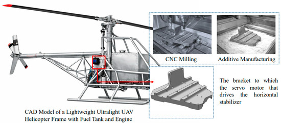
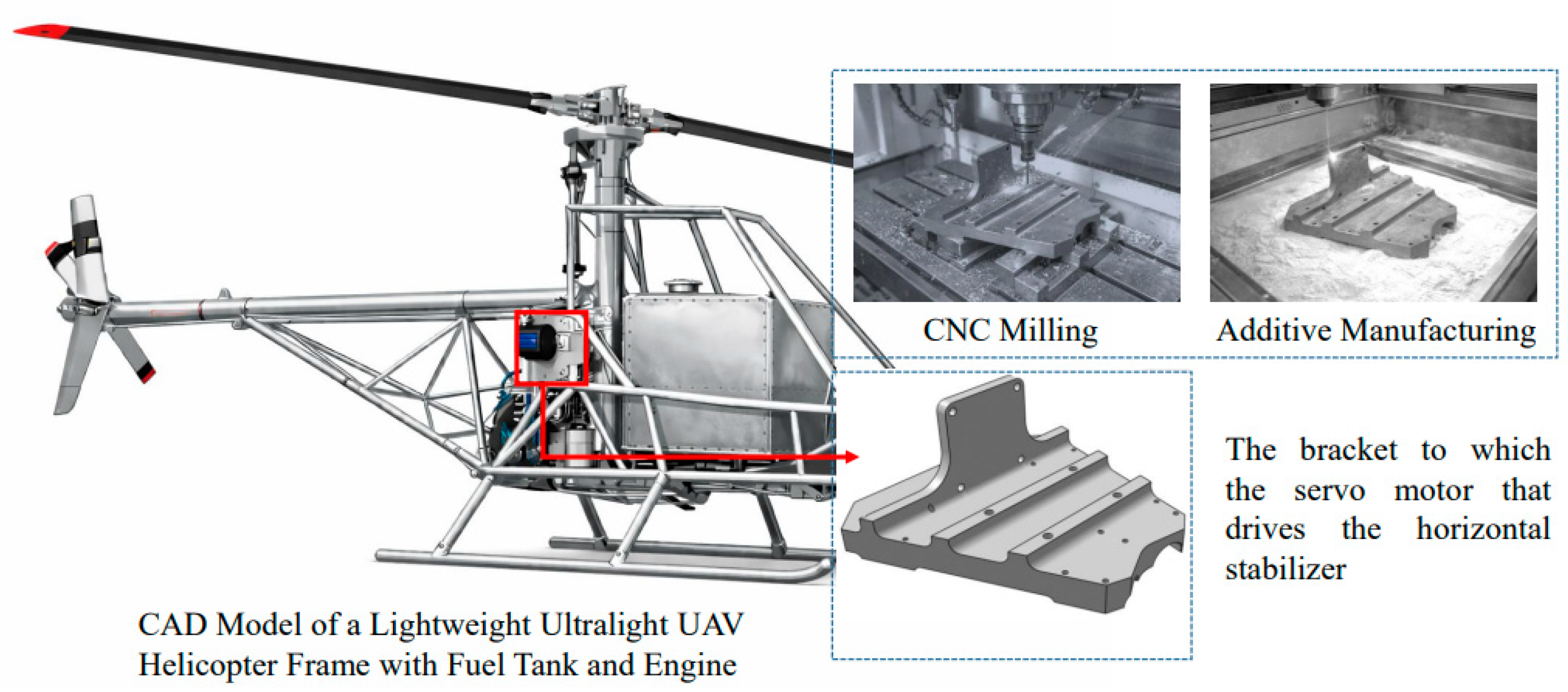
This study investigates the fabrication methods of the structural bracket to which the servo motor controlling horizontal stabilisation in a VTOL UAV is attached to the fuselage (Figure 1). This component plays a critical role in safely transmitting the actuator, which provides angle change in the horizontal stabiliser during flight, to the fuselage. Therefore, both geometric integrity and manufacturing method are directly important for flight safety. CNC milling provides high precision and surface quality, while AM offers flexibility and efficiency in material handling for more complex geometries.
Figure 1.
VTOL UAV frame and CAD model of the servo bracket controlling horizontal stabilisation.
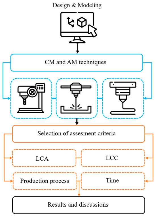
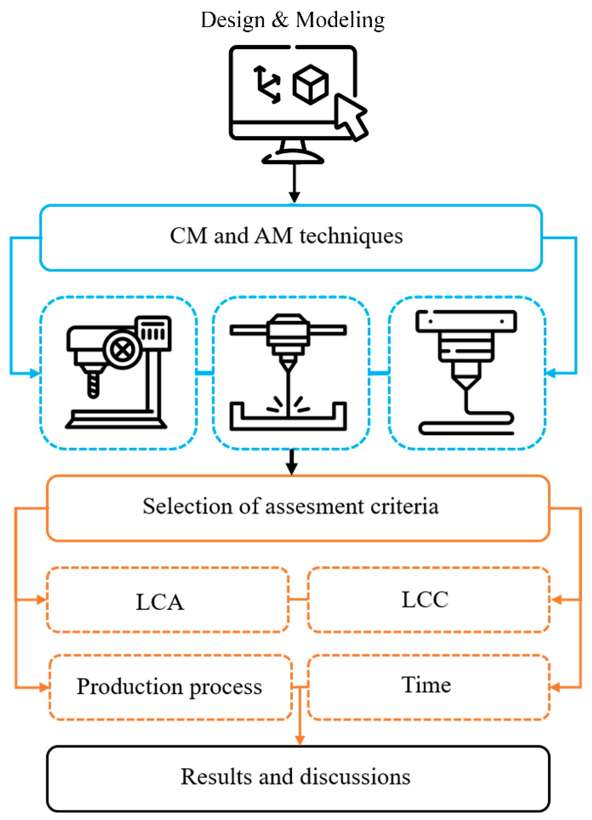
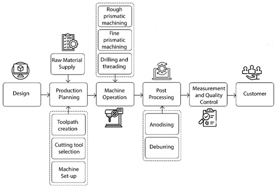
CM and AM were compared in terms of production processes, environmental impacts, production time, and cost. While CNC milling was selected as the CM method, SLM and MEX/M from AM technologies were considered. The study flow chart is shown in Figure 2.
Figure 2.
Flowchart of methodology.
2.1. Servo Bracket Design Criteria
The servo bracket is a critical structural component that ensures the servo motor is securely attached to the housing. As this component is part of a dynamic system, it is exposed not only to static loads, but also to continuous, repetitive vibration loads caused by rotor-induced excitation, body resonances, aerodynamic turbulence during flight, and sudden acceleration manoeuvres.
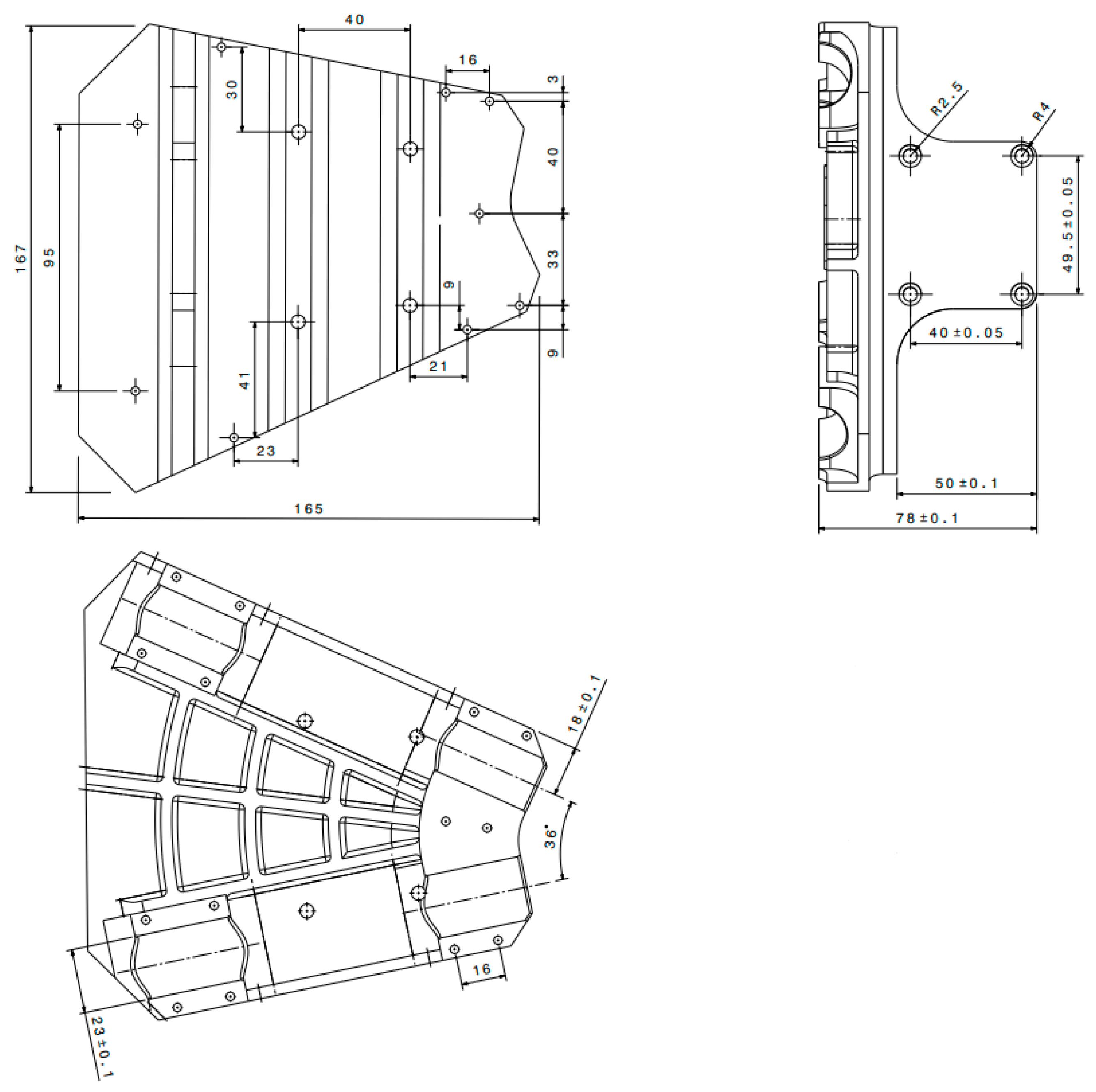
The component design incorporates a ribbed geometry based on the box profile principle to enhance both ease of assembly and load-bearing capacity. The lateral flanges are the primary load-bearing surfaces that transfer the thrust force and torque generated by the servo motor to the body structure. The flanges on the bottom and sides serve as interfaces for connecting to the UAV body. The bracket geometry incorporates rounded transitions and tool-accessible cross-sections as part of the manufacturability-oriented adaptations, ensuring compatibility with process constraints while preserving the core functional design. The overall dimensions of the part are shown in Figure 3.
Figure 3.
General dimensions of the servo bracket in mm (General dimensional tolerances: ISO 2768-1-m [30]).
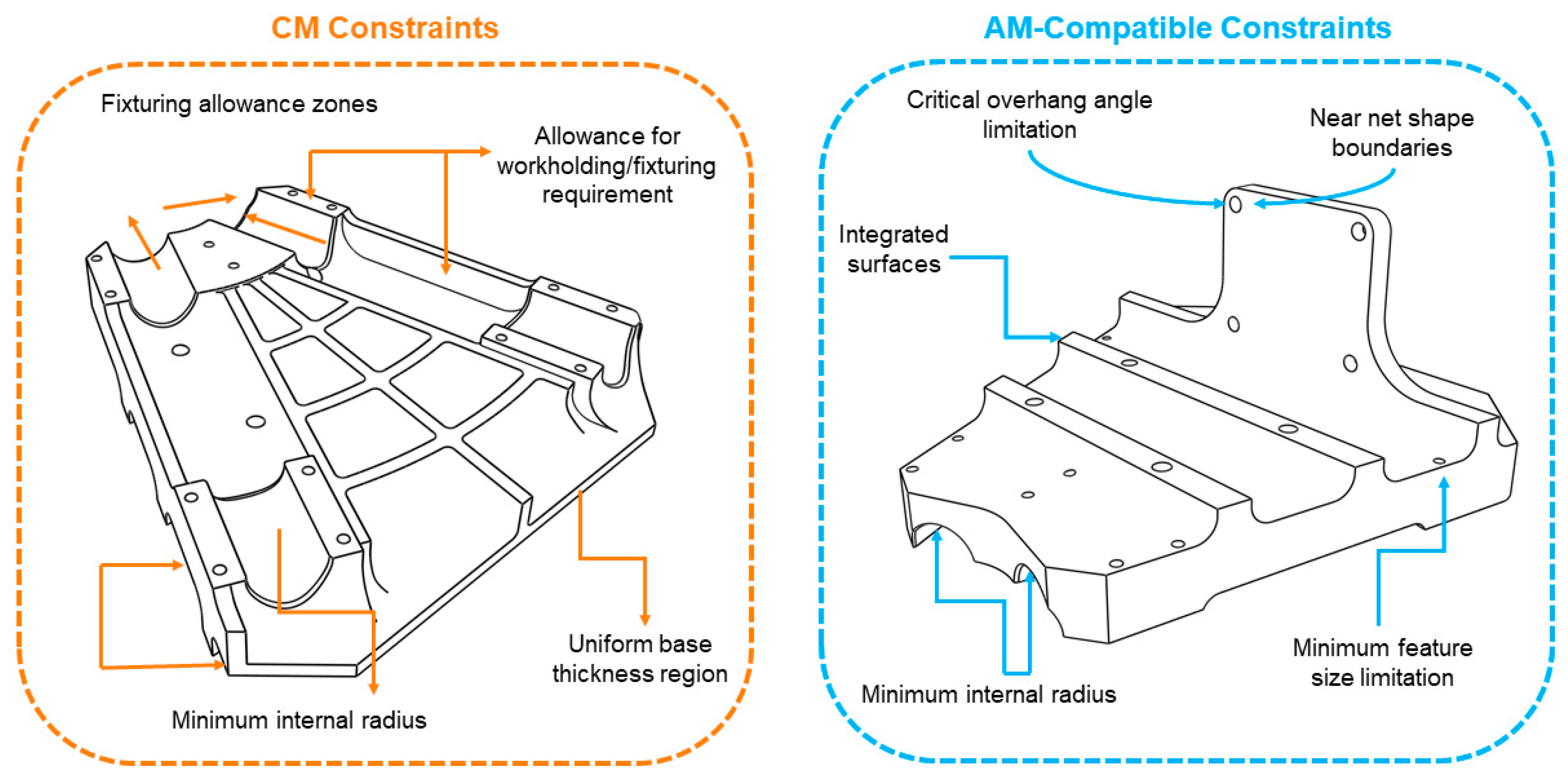
In the part design process, manufacturability-oriented geometric adaptations were considered to ensure compatibility with CM and AM technologies, while preserving the component’s core functional geometry for a fair life cycle-based comparison (Figure 4). In this context, the geometry was defined to meet the process-specific constraints of both SLM and MEX/M methods. Minimum wall thicknesses were determined based on process capabilities and build orientations were evaluated to reduce the need for support structures during production.
Figure 4.
Manufacturability-oriented geometric compatibility of the VTOL UAV servo bracket design across manufacturing routes.
In addition, design evaluations considered weight sensitivity specific to UAV platforms, structural adequacy under vibration, and integration requirements in confined spaces. In this context, the reduction in the need for support structures in SLM and the prediction of possible post-sintering shrinkage during the design phase in MEX/M were addressed. From a CNC machining perspective, tool accessibility and the naturally occurring high material loss during machining were considered as factors limiting design freedom.
2.2. Production Processes
This section explains the pre-processing, production, and post-processing steps for CNC milling, SLM, and MEX/M methods, as well as the equipment, materials, and production parameters used in these processes.
2.2.1. CNC Milling
The servo bracket is a structural component of the VTOL UAV’s tail-rotor control mechanism and plays a critical role in flight safety. The geometry was developed in CATIA V5 with manufacturability-oriented considerations to ensure process compatibility, without altering the core functional design. The stock material dimensions for the servo bracket with 175 × 166 × 78 mm were determined to be 220 × 180 × 80 mm to allow fixing with a vice on the CNC machine. AL6061 aluminium alloy was preferred as the stock material. According to the NASA Materials Data Manual, the mechanical properties of Al6061 alloy are given in Table 1. The CNC milling process is shown in Figure 5.
Table 1.
Mechanical properties of Al6061 alloy. [31].
Figure 5.
CNC milling process.
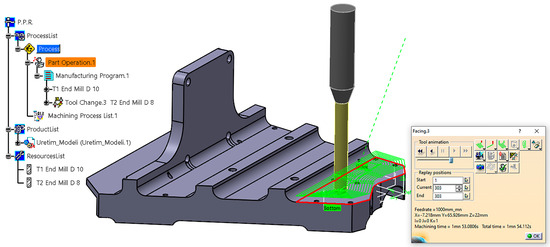
CNC milling starts with removing excess chips from the stock material with rough milling and ends with fine milling. The machining process was determined by the diameters of the cutting tools (Ø30 mm, Ø20 mm, Ø10 mm spherical and Ø8 and Ø5 mm drill bits), cutting speeds, feed rates and rotational speeds for the Spinner VC850 CNC milling machine. The cutting tool and parameters used in the metal-removal process are listed in Table 2. The tool path simulation is shown in Figure 6.
Table 2.
CNC milling parameters.
Figure 6.
The tool path simulation of the CNC milling process.
The total mass of Al6061 was 6.981 kg. After the process, finishing operations such as surface cleaning, deburring and anodising were applied. An additional 30 min were spent on installing the CNC machine and fixing the part in the vice. The final mass of the servo bracket was 0.597 kg.
2.2.2. Selective Laser Melting
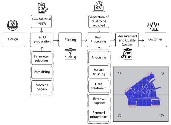
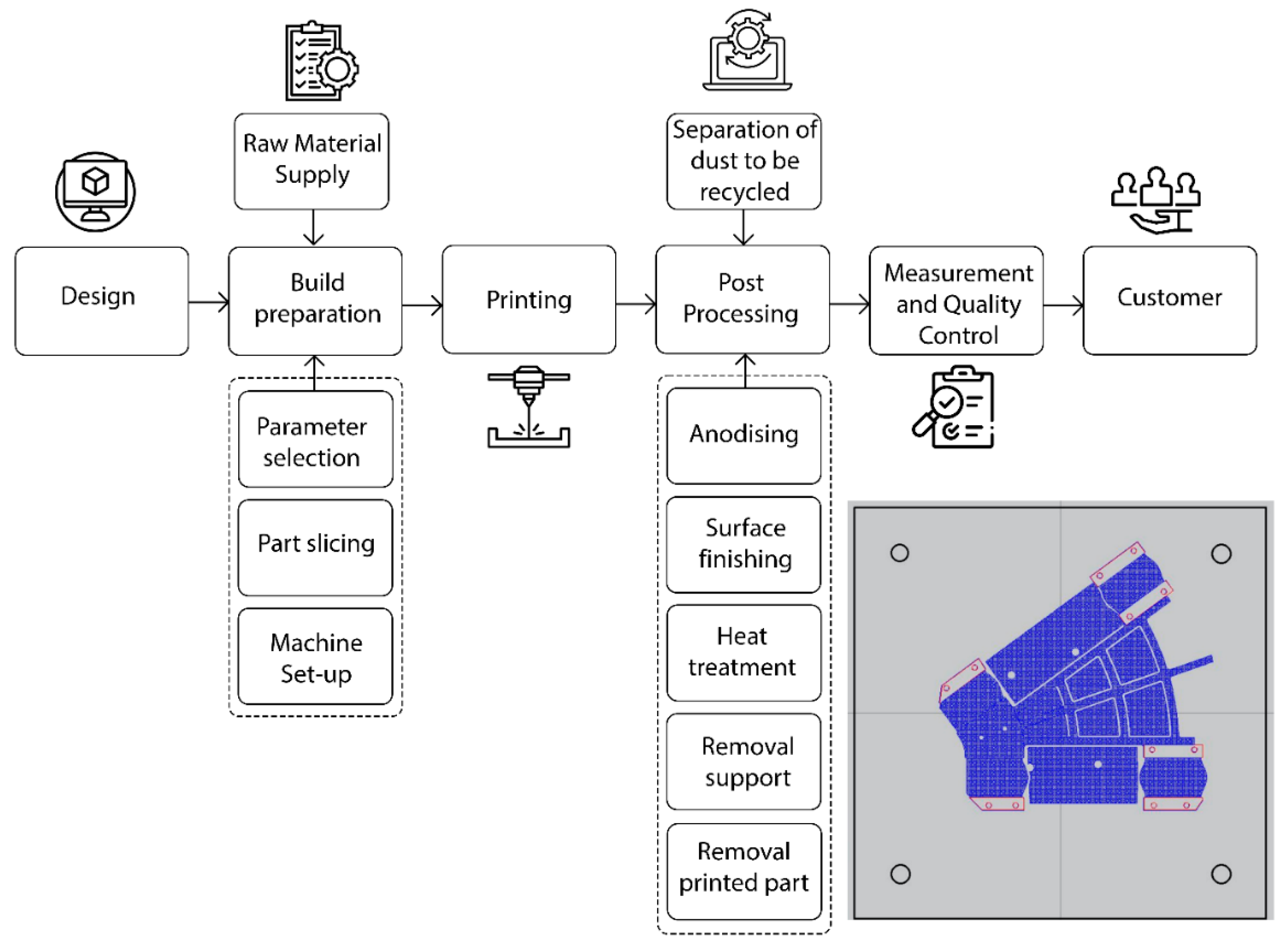
In SLM, after the 3D CAD model of the servo bracket was created, the model data required for production was generated by slicing in Materialise Magics (Figure 7). For the Concept Laser-M2 CUSING SLM machine, the laser intensity was 200 W and the laser spot diameter was 0.10 mm. The mass of the part, produced with 100% infill density and a layer thickness of 0.03 mm, was 0.595 kg (Table 3). In addition, the powder required to create support structures was also considered when manufacturing the product. A total of 10% of the part mass was considered a material allowance to create support structures during printing [32]. Accordingly, it was determined that approximately 0.655 kg of powder would be used in the production process. The total production time is 39 h and 44 min. After the production, the printing and support materials were removed from the table. After heat treatment and surface finishing, the part was anodised.
Figure 7.
SLM process.
Table 3.
SLM processing parameters.
2.2.3. Material Extrusion of Metals
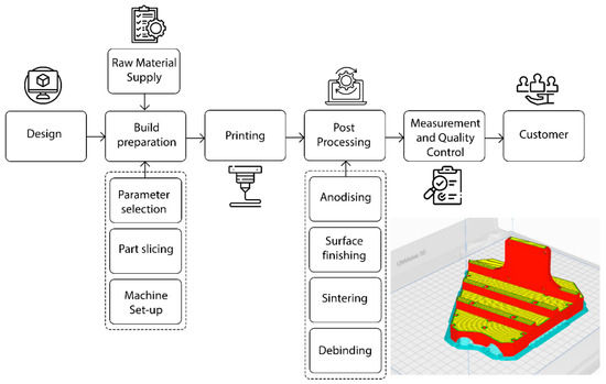
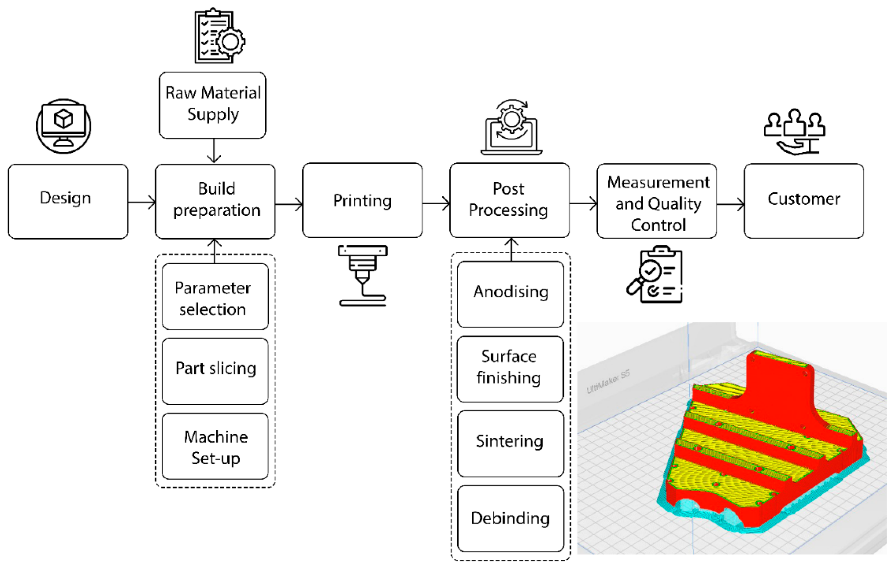
The MEX/M process comprises six basic stages: design, prepress preparation, printing, debinding, sintering, and finishing (Figure 8). MEX/M is a cost-effective multi-step additive manufacturing process that produces metal parts from a polymer–metal composite feedstock through printing, debinding, and sintering, with final quality governed by feedstock composition and processing conditions [33,34]. MEX/M required 1.055 g of Al6061 filament used in an Ultimaker S5-type printer. Based on the specified print parameters (Table 4), the total print time is 57 h and 49 min.
Figure 8.
MEX/M process.
Table 4.
MEX/M Parameters.
The thermal debinding temperature is 425–450 °C, and the sintering temperature is 625 °C in MEX/M [35,36]. Malone (2022) used temperature holding times of 5, 4, and 6 h at 280 °C, 330 °C, and 450 °C, respectively, in the combined thermal binder removal-sintering thermal cycle he developed [35]. The heating rate for thermal debinding is 1 °C/min. After the thermal debinding, a sintering temperature of 625 °C was selected for 2.5 h with a heating rate of 3 °C/min. The debinding time for the servo bracket is 22 h and 30 min, and the sintering time is 3 h and 28 min. After production, the final part mass was determined to be 0.671 kg.
2.3. Life Cycle Assessment
LCA is an environmental analysis method that enables the comprehensive assessment of the environmental impacts of different production processes [20]. LCA evaluates input sources, such as raw materials and energy consumption, and outputs, such as atmospheric emissions and solid waste, that a production process releases into the environment [37].
In this study, the environmental impacts of CNC milling, SLM, and MEX/M methods were calculated using Eco-it software for LCA analysis. In this approach, the results are expressed in points (Pt) and millipoints (mPt). Here, 1 Pt represents the total annual environmental burden of an average European resident, and 1 mPt corresponds to one thousandth of a point (1 mPt = 0.001 Pt). These weighted endpoint indicators allow for the comparison of different production methods by converting multiple impact categories into a single environmental score [38,39]. The CO2 emission (kg CO2-eq) values reported in the study were calculated by modelling the material consumption, energy use, and process inputs determined for each production method in Eco-it software. CO2 emission results were derived from the relevant impact categories using characterisation factors defined in the ReCiPe method.
2.4. Life Cycle Cost
LCC is an economic analysis method used to measure the financial costs incurred throughout a product’s life cycle [40]. Kokare et al. (2023) formulated the expressions used to compute the machine usage cost and the material cost per part within the LCC model (Equations (1) and (2)) [32]. LCC determines maintenance and operating costs as well as raw material costs [41,42]. Thus, necessary improvements can be made by determining the economic impacts of the product life cycle [43].
where:
(€): Machine usage cost.
(€): Purchasing cost of a machine tool.
(€): Maintenance cost of a machine tool.
(€): Cost of tooling such as jigs, fixtures and cutting tools.
(h): Total available time of a machine tool.
(h): Time for which a machine is used, including its set-up, processing time and clean-up.
where:
(kg): The amount of the total raw material consumed, including the final part and waste material.
(€/kg): Cost of 1 kg of raw material
3. Results and Discussion
This section comparatively examines the performance of different manufacturing methods for servo brackets—a structural component used in VTOL UAV platforms. The resulting LCA and LCC results offer insights into how UAV components can be optimised in terms of environmental sustainability, cost-effectiveness, and manufacturability. The findings aim to guide design and manufacturing decisions, particularly in selecting the most suitable production method for low-volume, customised UAV platforms.
3.1. Production Process Results
In CNC milling, tool path extraction from the CAD model, selection of appropriate cutting tools and machining parameters, and design of dedicated fixtures for the part are required. In contrast, SLM and MEX/M processes largely rely on digital workflows prior to production; the CAD model is directed to printing, support structures are generated where necessary, and the model is sliced into thin layers and sent to the machine. Particularly in MEX/M, the model dimensions must be scaled up in advance to compensate for shrinkage occurring after sintering [44]. Although parts can reach 95–99% of theoretical density after sintering, a linear shrinkage of approximately 15–20% occurs in the part dimensions [33]. Since this shrinkage can be anisotropic and is influenced by process variables, such as furnace atmosphere, part placement, and section thickness, deviations in final dimensional accuracy and geometric distortions may occur. This effect is especially noticeable in thin-walled or tight-tolerance geometries, where it may appear as warping, variations in hole diameters, or concentricity errors. Therefore, parts are designed larger to account for sintering shrinkage [34]. Advanced binder systems, optimised sintering cycles, and post-processing methods such as polishing, sandblasting, heat treatment, and hot isostatic pressing can further improve dimensional accuracy and surface characteristics [45,46]. Overall, while the MEX/M process can provide dimensional accuracy within a predictable engineering range, it remains more limited compared to the precision and repeatability of CNC machining, which removes material directly from dense and homogeneous stock material.
CNC achieves smoother surface finishes compared to AM. However, due to limitations in cutting tool geometry and accessibility, it faces challenges in machining complex internal features, such as internal channels and sharp corners. In contrast, SLM enables the fabrication of lightweight structures and internal channels within complex geometries without requiring part repositioning during manufacturing. Nevertheless, the primary limitation of internal channels in SLM is the need to effectively remove unmelted metal powder from enclosed cavities, which may impose additional design constraints. The layer-wise powder-melting process in SLM is relatively slow, and residual stresses accumulate due to the high thermal gradients formed in each layer. Commercial Al6061 powder alloy is prone to hot cracking during laser melting. Therefore, specific processing parameters or modified powder compositions may be required to achieve stable fabrication [47]. The low layer thickness and small laser spot size in SLM allow finer details compared to the nozzle diameter and layer thickness limitations of MEX/M. In the MEX/M process, interlayer porosity and shrinkage during debinding and sintering may result in parts with lower mechanical properties compared to SLM [44].
MEX/M may introduce interlayer porosity that can influence fatigue behaviour. Recent studies demonstrate that the process can produce structurally reliable aluminium components suitable for aerospace-related applications. Ceylan (2025) reported that MEX/M parts can satisfy structural requirements for aerospace components despite slightly lower strength than bulk materials [48]. Likewise, Zhang et al. (2025) showed that filament-based MEX processing of Al-6061 can achieve high densification levels, reaching ≈99% density for density cubes and ≈97 ± 0.9% for tensile specimens, resulting in stable mechanical properties and ductile fracture behaviour with good interlayer bonding [49]. Such mechanical performance is consistent with the known strength–ductility balance of Al-6061 alloys reported in the literature [50]. In addition, recent studies emphasise that MEX/M systems are increasingly considered suitable for industrial applications and scalable production with further process optimization [51,52]. Considering these mechanical properties and the moderate loading conditions typically experienced by UAV servo brackets, the MEX/M-manufactured Al-6061 component used in this study can reasonably meet the structural safety and fatigue requirements of VTOL platforms.
CNC-manufactured parts require only minor additional processes, such as deburring and surface finishing, resulting in much smoother surfaces than those produced by AM. SLM-printed parts require a series of mandatory processes such as support structure removal, heat treatment, precision machining, sandblasting, or polishing. These processes are crucial for producing reliable prints for critical applications, such as in aerospace. In MEX/M, the printed green part does not represent a fully functional metal component. Following printing, the binder is removed during the debinding stage to obtain a brown part. The metal particles are then sintered at elevated temperatures in a controlled-atmosphere furnace to promote densification and metallurgical bonding.
3.2. Environmental Impacts
First, the power requirements of the devices were determined in order to calculate the environmental impact of the production methods (Table 5). The total power requirement of the Spinner VC850 is approximately 13 kW [53]. However, since the machine does not operate continuously at maximum power, it consumes approximately 60% (7.8 kW) of its maximum power on average. Since the machine’s total operating time is 2 h 48 min, the total electricity consumption is 19.34 kWh. The average emission factor for electricity production in Turkey is approximately 0.42 kg CO2-eq/kWh when non-renewable energy sources are included. Accordingly, the total emission value from non-renewable energy sources is 8.12 kg CO2-eq.
Table 5.
Inventory data of manufacturing methods.
According to Faludi et al. (2016), the environmental impacts associated with equipment construction are typically excluded from LCA, as the depreciation impact of a single part produced is considered insignificant [54]. Wang et al. (2020) stated that SLM impacts are more significant for ultralight designs, and the main cause of environmental impact is electricity [55]. Therefore, the LCA analysis data were generated based on the environmental impacts and energy consumption of materials in the SLM. The maximum power consumption of the Concept Laser-M2 CUSING is approximately 6.8 kW [56]. Since the printing time is 39.73 h, the total electricity consumption is 270.16 kWh. The total emission value from non-renewable energy sources is determined as 113.46 kg CO2-eq. The total power requirement of the Ultimaker S5 is 0.5 kW [57]. Since the printing time is 57 h and 49 min, the total electricity consumption is 28.91 kWh. The total emission value from non-renewable energy sources is determined as 12.14 kg CO2-eq. The debinding and sintering stages were performed under a controlled nitrogen furnace atmosphere to ensure thermal stability and material integrity. The average power consumption for this furnace was reported as 10 kW [58]. Accordingly, the total electricity consumption for debinding and sintering processes, which lasted a total of 25 h and 58 min, was 255.8 kWh. Thus, the total CO2 emission was calculated as 107.43 kg CO2-eq.
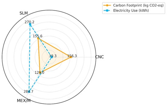
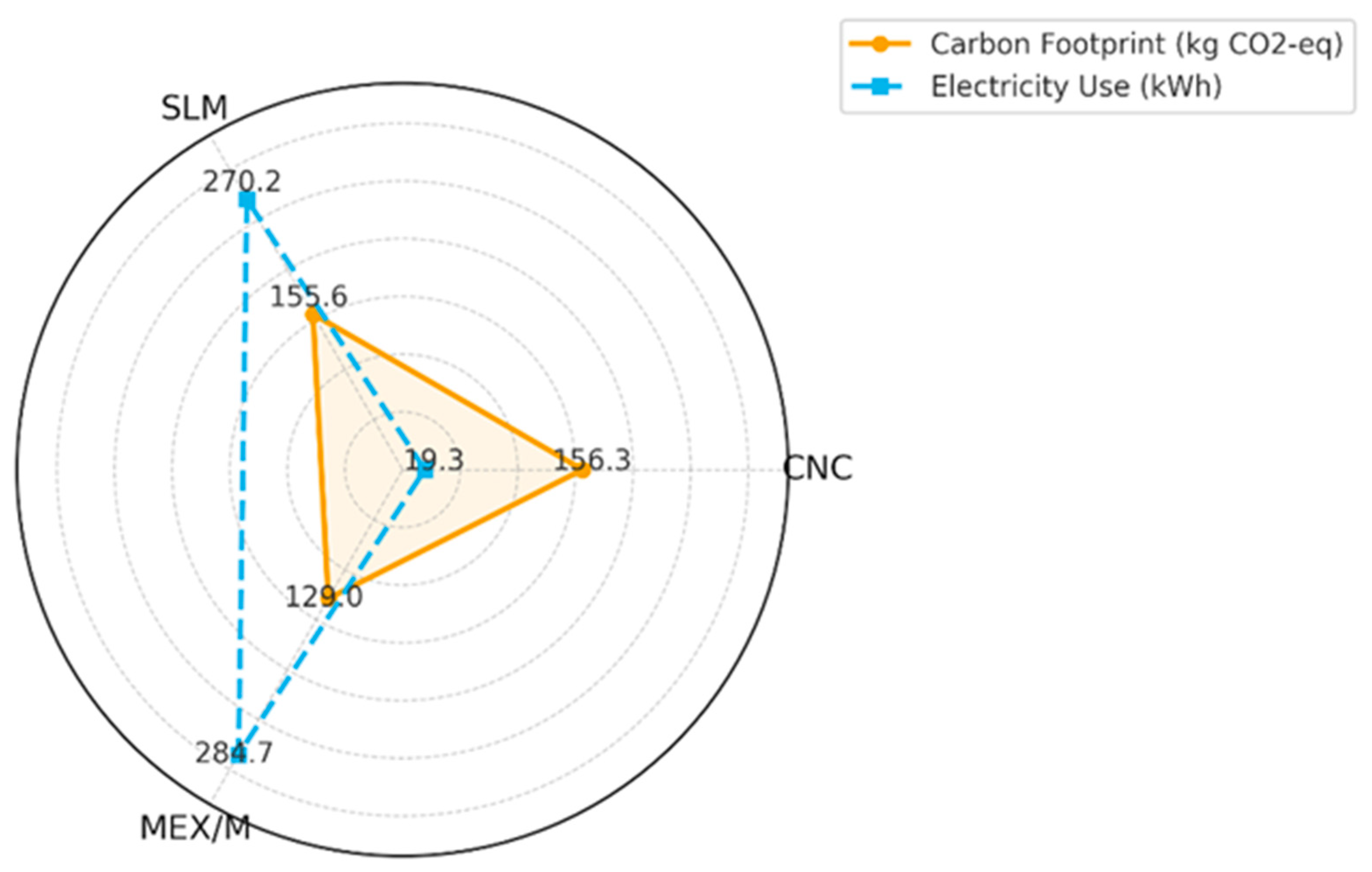
Carbon footprint results per product show that CNC and SLM produce similarly high greenhouse gas emissions, while MEX/M has a significantly lower carbon footprint. Total CO2 emissions of the processes are presented in Figure 9. The primary reason for the high emissions from the CNC machine is that a large portion (6.384 kg) of the 6.98 kg of aluminium alloy used is wasted as chips and producing this raw material is energy-intensive. In fact, approximately half of the CNC’s total carbon emissions come from material production and waste. In contrast, the machine’s electricity consumption contributes less to emissions. In the SLM, the main factor increasing the carbon footprint is high electricity consumption. A total of 270.1 kWh of energy was used during 39.7 h of production, resulting in approximately 113.5 kg of CO2 emissions. Since less powder is used in SLM, material waste is minimal. Therefore, material-related emissions accounted for approximately 25% of the total, at 39 kg CO2. The carbon footprint is minimal due to the very low amount of metal used in the MEX/M. Almost all of the 0.67 kg of Al alloy powder used was incorporated into the final product. In addition, 0.384 kg of PLA-based binder polymer was used, and some emissions were generated as it was burned before sintering; however, its low mass limited its impact on the total carbon footprint.
Figure 9.
Comparing carbon footprint and electricity consumption on a unit product basis.
Energy consumption results show that CNC uses significantly less electricity compared to other methods. The CNC machine consumed only 19.3 kWh over 2 h and 48 min of production time. In contrast, the SLM machine, which operated for approximately 40 h, consumed 270.2 kWh. In the MEX/M process, there is a two-stage consumption: during the printing stage, which lasted 57 h and 49 min, the Ultimaker printer consumed a low amount of energy, 28.9 kWh, while the sintering furnace, which operated for 25 h and 58 min, constituted the largest energy load of the process with approximately 255.8 kWh. These results show that, despite CNC’s low electricity consumption, its overall energy efficiency is low because it generates significant material waste during the production of complex parts. Indeed, Faludi et al. (2016) reported that 85% of the total energy in CNC is spent on machining and processing excess material [54]. AM significantly reduces the carbon footprint of producing the same part by minimising material waste. Yusoh et al. (2021) stated that AM can provide energy savings of up to 45–61% depending on the technology used [59]. Tang et al. (2016) also reported that a part optimised with the binder spray method reduced CO2 emissions by 46% compared to CNC [60]. Similarly, Serres et al. (2011) showed that the environmental impact can be reduced by up to 70% in titanium alloy parts produced by laser powder deposition, thanks to the absence of scrap material [61].
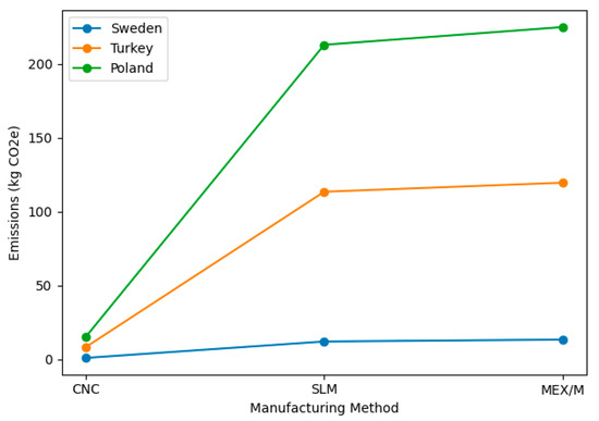
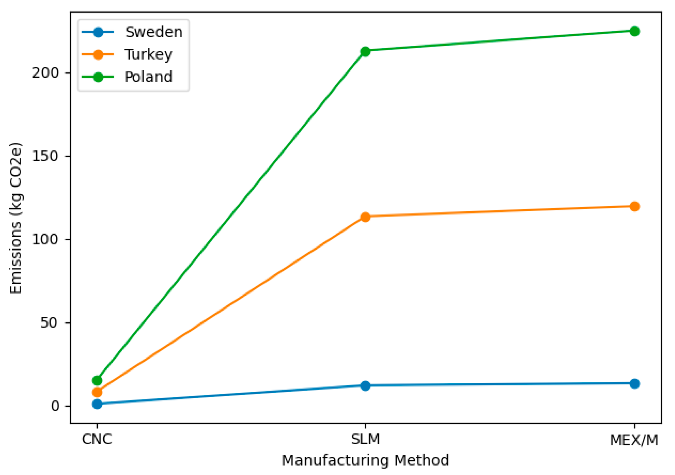
Furthermore, different grid emission factors were considered to evaluate the influence of regional electricity mixes on the environmental results. Although an electricity emission factor of 0.42 kg CO2-eq/kWh was used for Turkey in this study, countries with low-carbon electricity systems, such as Sweden, Lithuania and France, typically exhibit electricity carbon intensities below 0.10–0.20 kg CO2-eq/kWh [62]. In contrast, electricity systems in countries such as Poland, Estonia or Greece may exceed 0.70–0.80 kg CO2-eq/kWh [62]. To assess the influence of regional electricity mixes on the LCA results, grid emission factors representing low-carbon (Sweden: 0.013 kg CO2-eq/kWh) and carbon-intensive (Poland: 0.773 kg CO2-eq/kWh) electricity systems were considered. For SLM, the total electricity-related emissions were calculated as 12 kg CO2-eq for Sweden and 213 kg CO2-eq for Poland. Similarly, for the MEX/M process, electricity-related emissions were 13.3 kg CO2-eq in Sweden and 225 kg CO2-eq in Poland. When all non-electric inventory items are kept constant, the results indicate that the total carbon footprint of electricity-intensive routes is highly dependent on the electricity grid. In contrast, CNC milling is less sensitive to the electricity mix due to its relatively low electricity consumption, varying between approximately 1 and 15 kg CO2-eq under the same scenarios. The variation in total CO2 emissions for CNC, SLM, and MEX/M manufacturing routes under different electricity grid emission factors for Sweden, Turkey, and Poland is presented in Figure 10.
Figure 10.
CO2 emissions of CNC, SLM and MEX/M manufacturing routes under different electricity grid emission factors.
3.3. Production Lead Time
The manufacturing time for the Al6061 alloy VTOL UAV tail servo bracket varies significantly depending on the selected manufacturing method. The formula (Equation (3)) proposed by Achillas et al. (2017) was used to calculate the product lead time for CNC milling, SLM, and MEX/M [63].
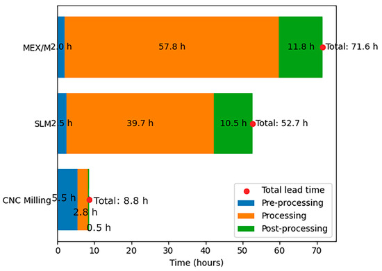
Firstly, pre-processing for CNC milling includes machine setup (2 h), cutting tool selection (30 min), and tool path generation (3 h) (Equation (4)). Therefore, the total pre-processing time for milling is about 5 h 30 min. Production time in CNC milling includes rough-fine machining (1.34 h + 43 min) and drilling-threading (12 min) steps (Equation (5)). Total machine operation time is approximately 2 h 48 min. The post-processing process for CNC milling includes anodising (30 min) and deburring (3 min) steps (Equation (6)). Thus, the total production lead time for CNC milling is 8 h 51 min.
The pre-processing in the SLM takes approximately 2.5 h in total, including machine setup (1.5 h), slicing (30 min), and parameter selection (30 min) (Equation (7)). The printing time is 39 h and 44 min (Equation (8)). These times can vary depending on equipment, software, and operator experience; complex geometries or special parameter requirements can particularly increase the time. Therefore, careful planning of the pre-processing steps is recommended for efficient management of the production process. The post-processing steps, including part removal from the platform (1 h), support cleaning (2 h), heat treatment (4 h), surface treatments (3 h), and anodizing (30 min), take a total of 10.5 h (Equation (9)). These steps may vary depending on factors such as part size, material type, and the desired surface finish. Thus, the total production time for SLM is 52 h and 44 min.
The pre-processing of the MEX/M, including machine setup, slicing, and parameter selection, takes a total of 2 h (Equation (10)). The Ultimaker S5 setup takes approximately 1 h. Slicing takes 30 min, depending on the part’s complexity, and printing parameters are determined in approximately 30 min, depending on the material and desired quality. The printing time is calculated to be 57 h and 49 min (Equation (11)). The final processing consists of binder removal, sintering, surface treatments, and anodising (Equation (12)). Binder removal takes 6 h at 450 °C, followed by sintering at 625 °C for 2 h. Grinding, polishing, or sandblasting to improve surface quality takes 3 h. Finally, anodising is performed for 45 min to increase corrosion resistance and improve the part’s aesthetic appearance. The total time for these steps is 11 h and 45 min. Thus, the total production time for MEX/M is 71 h and 34 min.
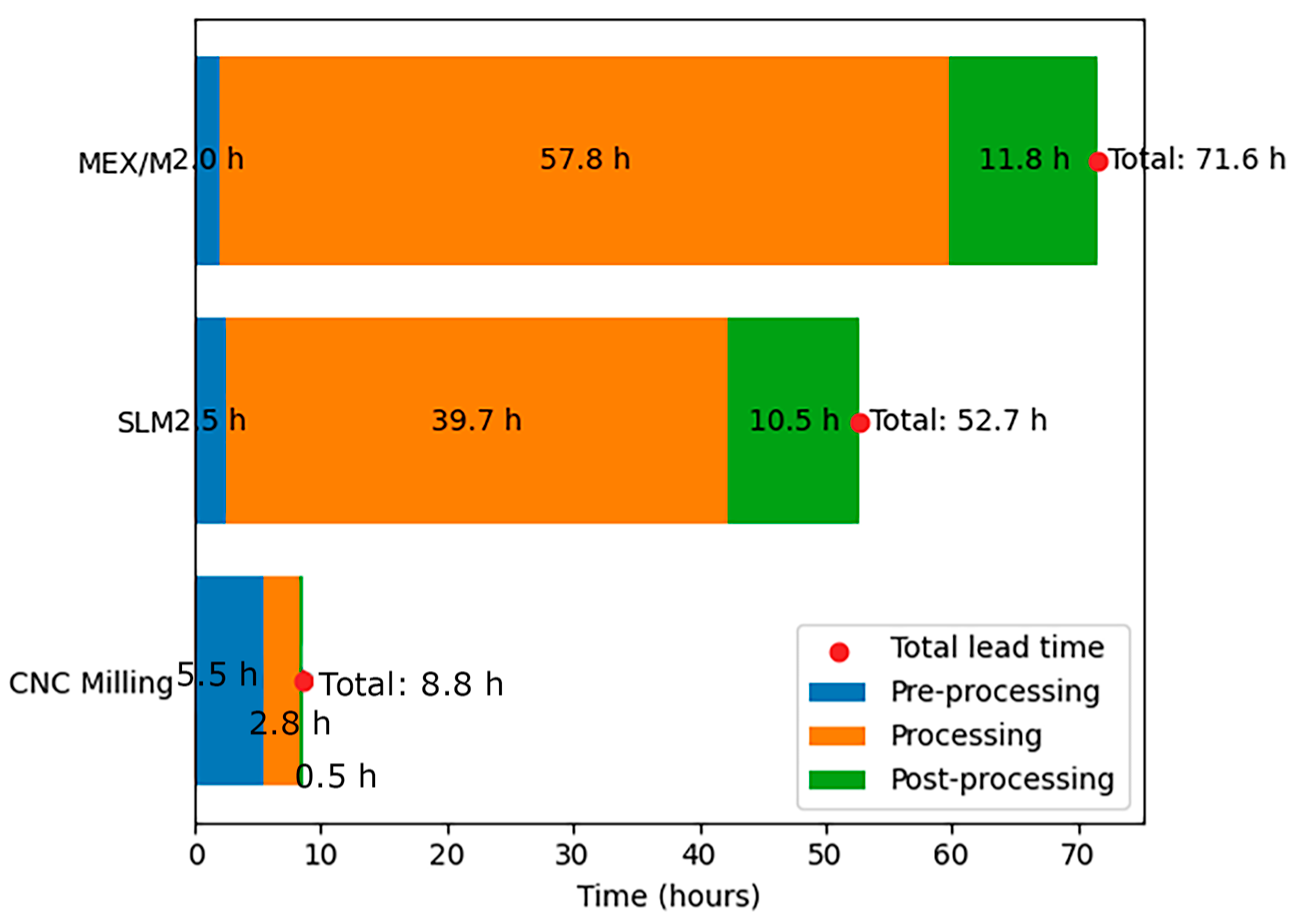
Figure 11 shows the production lead time distributions (pre-processing, processing, and post-processing) for CNC milling, SLM, and MEX/M, with the total lead time.
Figure 11.
Production lead time distributions.
3.4. Cost Results
Table 6 presents the principal cost components incorporated into the LCC framework for the three manufacturing routes. The machine investment cost associated with SLM is considerably higher than that of CNC milling and, in particular, MEX/M. A similar pattern is observed for annual maintenance expenditures, which can be attributed to the higher technological complexity and stringent operational requirements of powder bed fusion systems. By contrast, MEX/M is characterised by a substantially lower initial capital investment and relatively limited maintenance requirements, thereby representing a less capital-intensive and more economically accessible manufacturing alternative.
Table 6.
Main cost components for LCC.
Regarding material costs, significant differences are also observed among the three manufacturing routes. In CNC milling, the unit price of Al6061 material is 5 €/kg, and 8.55 kg of stock material is used. Since a large portion of the block is removed as chips during machining, the material cost per part is calculated as €42.75. Considering that the finished part weighs less than 1 kg, approximately 7–8 kg of material is wasted; however, this is accounted for in the cost calculation because the manufacturer is required to purchase the entire 8.55 kg block. In SLM, the material cost per part is calculated as €58.9, based on approximately 655 g of Al6061 powder with a unit price of 90 €/kg. Although powder material is expensive, the material cost of SLM remains comparable to CNC milling because only the required 0.65 kg is consumed, and the remaining powder can be reused. Despite the lower unit price of CNC material, the waste rate reaching up to 90% eliminates this cost advantage. For MEX/M, the material cost per part is determined as €126.6, based on 1.055 kg of Al6061 filament at a unit price of 120 €/kg. This result indicates that MEX/M has a higher material cost compared to SLM. The literature reports that filaments are more expensive due to the inclusion of binder materials in addition to metal powder and their production at relatively low volumes [33]. Although consumables used during the sintering stage contribute to the overall cost, their impact remains negligible in the total cost structure.
From a tooling cost perspective, the three manufacturing routes exhibit fundamentally different cost structures. In CNC milling, tooling includes wear-prone cutting tools and fixturing systems. Tool life significantly affects cost, energy consumption, and work quality [67]. On the other hand, SLM inherently require post-processing steps including powder removal, support structure elimination, and heat treatment to mitigate residual stresses and achieve the desired mechanical performance [68,69]. In MEX/M, the green part must undergo debinding and high-temperature sintering to achieve full densification and metallurgical bonding [70]. These additional operations necessitate dedicated auxiliary equipment and contribute to both capital expenditure and operational labour costs.
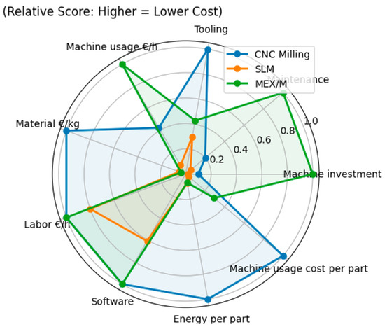
The machines were assumed to operate over a seven-year period under a production schedule of 250 days per year and three shifts per day (8 h per shift), with an availability rate of 80%. The hourly machine cost was calculated by dividing the total of capital investment, maintenance, and tooling expenses by the total available operating time () [65]. Based on the data presented in Table 6, the hourly machine costs were determined as 4.64 €/h for CNC milling, 24.10 €/h for SLM, and 1.96 €/h for MEX/M. Considering the respective lead times (), the resulting machine usage costs () per part were calculated as 41.06 € for CNC milling, 1270 € for SLM, and 140.27 € for MEX/M. The literature also emphasises that machine depreciation is the largest expense item in metal powder bed fusion [71]. These results indicate that the combined effect of processing time and hourly machine cost is a decisive factor in differentiating the economic performance of the evaluated manufacturing routes.
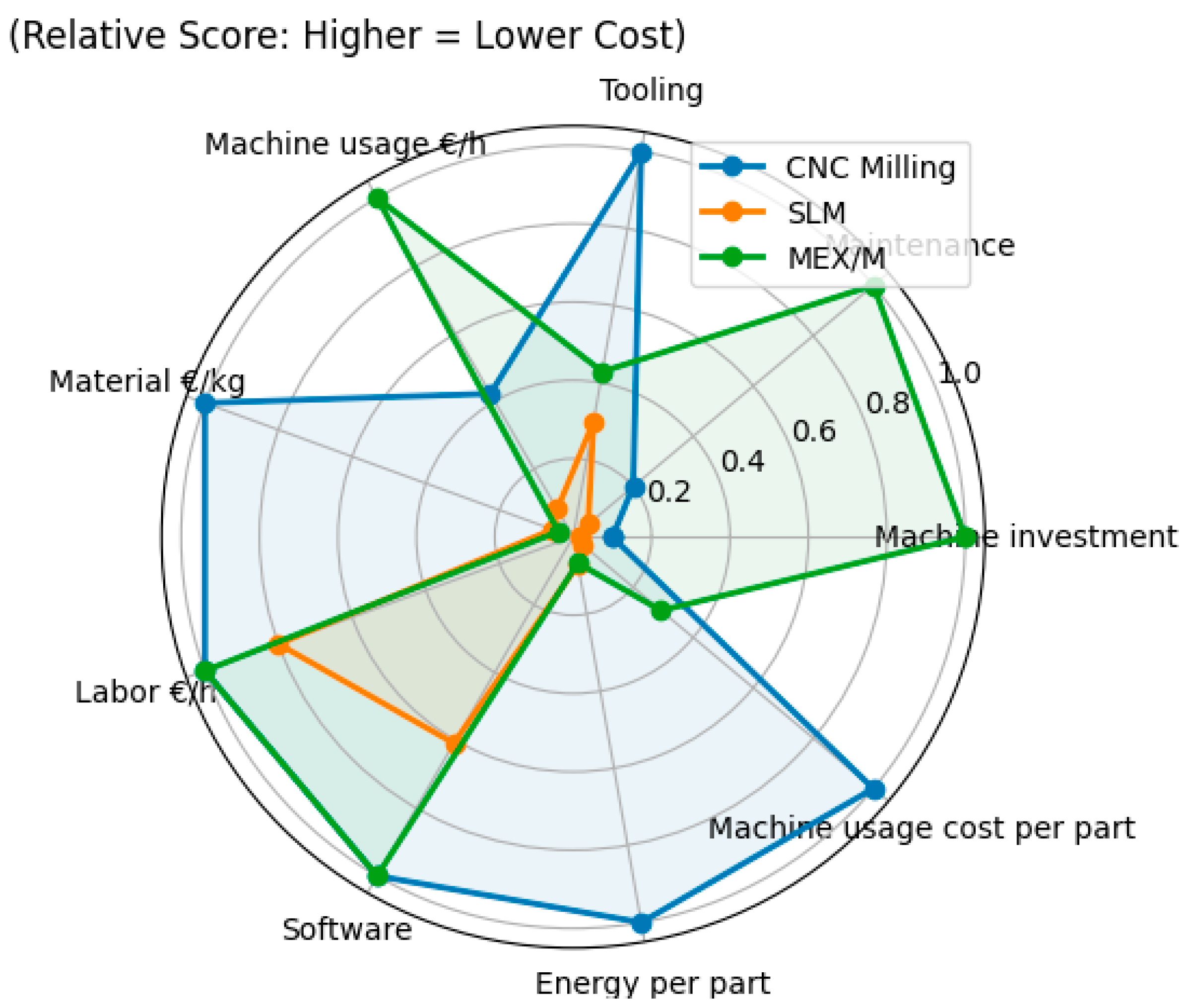
In addition to the total machine usage cost, the overall cost assessment incorporates labour expenses, software licencing fees, and energy consumption costs. Hourly labour rates were determined based on the average monthly wage levels of skilled manufacturing operators in Turkey, including employer contributions and social security expenses. These figures were converted into equivalent hourly rates by assuming standard full-time industrial working hours. Accordingly, a rate of €12/hour was adopted for CNC milling and MEX/M, whereas a higher rate of €15/hour was assigned to SLM due to its advanced process control and monitoring requirements. Regarding software-related cost components, the annual cost was set at €7000 for CATIA Machining used in CNC milling, €11,500 for Materialise Magics used in SLM, and €0 for Ultimaker Cura used in MEX/M. While Cura does not impose a licencing fee, the higher annual fees for CATIA and Magics add to the fixed costs of CNC milling and SLM. According to the electricity unit price in Turkey of €0.09/kWh [72], the calculated energy cost per part is €1.74 for CNC milling and €24.31 for SLM. For MEX/M, the energy cost is €2.60 for printing and €23.02 for binder removal and sintering, resulting in a total of €25.62 per part. Figure 12 shows a chart of LCC component scores (higher values indicate lower cost), enabling a clearer comparison of CNC milling, SLM, and MEX/M across cost categories.
Figure 12.
LCC component scores (higher values indicate lower cost).
4. Conclusions
This study comparatively evaluated CNC milling, SLM, and MEX/M manufacturing routes for a servo bracket used in a VTOL UAV platform from environmental, economic, and operational perspectives. The novelty of this study lies in the comparative evaluation of CNC, SLM, and MEX/M using life cycle indicators. While the environmental performance of established metal AM technologies has been widely studied, research on MEX/M remains limited due to its recent development. This study provides a sustainability-oriented comparison for manufacturing method selection in low-volume aerospace components.
The results indicate that each manufacturing method presents distinct advantages and limitations, and that the environmental benefits commonly attributed to metal additive manufacturing depend strongly on the manufacturing context. While SLM and MEX/M offer high design freedom and efficient material use, their higher electricity consumption, longer production times, and additional steps such as sintering can increase the overall carbon footprint. In contrast, CNC milling offers shorter production times and lower energy intensity, although it generates significant material waste. Consequently, CNC is more suitable for large-scale and low-complexity parts, whereas SLM provides advantages for complex and low-volume components, and MEX/M offers flexibility for small-scale production and distributed manufacturing. These findings highlight that the sustainability performance of metal AM should be evaluated not only in terms of material savings but also considering production volume, design complexity, energy consumption, and system boundaries.
It should also be noted that the results of this study are derived from a unit-part comparison conducted under low production volume conditions while maintaining identical functional geometry. Under such conditions, operational factors such as setup requirements, post-processing stages, and thermal treatments may significantly affect the unit cost and environmental performance of AM processes. In the Turkish defence and aerospace sector, production is typically carried out in limited batches and project-based manufacturing environments rather than high-volume mass production. Therefore, the findings of this study should be interpreted as a case-based evaluation reflecting the sustainability performance of different manufacturing routes under low-volume production scenarios.
Future trends emerging from this study indicate important directions for the development of metal AM in VTOL UAV applications. Lightweight AM-enabled components can reduce operational energy demand and related emissions during service life. Including post-processing stages in life cycle assessments enables a more realistic evaluation of AM sustainability. Moreover, advances in hybrid manufacturing, high-throughput systems, and the use of renewable energy are expected to further improve the economic and environmental performance of metal AM.
Funding
This research received no external funding.
Institutional Review Board Statement
Not applicable.
Informed Consent Statement
Not applicable.
Data Availability Statement
The data and materials supporting the findings of this study are available within the article. For additional inquiries, please contact the corresponding author.
Conflicts of Interest
The author declares no conflicts of interest.
Abbreviations
The following abbreviations are used in this manuscript:
| AM | Additive Manufacturing |
| CM | Conventional Manufacturing |
| LCA | Life Cycle Assessment |
| LCC | Life Cycle Cost |
| MEX/M | Metal Extrusion Additive Manufacturing |
| SLM | Selective Laser Melting |
| UAV | Unmanned Aerial Vehicle |
| VTOL | Vertical Take-Off and Landing |
References
- Kabir, R.H.; Lee, K. Wildlife monitoring using a multi-UAV system with optimal transport theory. Appl. Sci. 2021, 11, 4070. [Google Scholar] [CrossRef] [Scilit]
- Mendu, B.; Mbuli, N. State-of-the-Art Review on the Application of Unmanned Aerial Vehicles (UAVs) in Power Line Inspections: Current Innovations, Trends, and Future Prospects. Drones 2025, 9, 265. [Google Scholar] [CrossRef] [Scilit]
- Xu, H.; Yi, L.; Li, C.; Sun, Y.; Hou, L.; Bai, J.; Kong, F.; Han, X.; Lan, Y. Design and Experiment of Ecological Plant Protection UAV Based on Ozonated Water Spraying. Drones 2023, 7, 291. [Google Scholar] [CrossRef] [Scilit]
- Jahani, H.; Khosravi, Y.; Kargar, B.; Ong, K.L.; Arisian, S. Exploring the role of drones and UAVs in logistics and supply chain management: A novel text-based literature review. Int. J. Prod. Res. 2025, 63, 1873–1897. [Google Scholar] [CrossRef] [Scilit]
- Guo, H.; Li, M.; Sun, P.; Zhao, C.; Zuo, W.; Li, X. Lightweight and maintainable rotary-wing UAV frame from configurable design to detailed design. Adv. Mech. Eng. 2021, 13, 1–10. [Google Scholar] [CrossRef] [Scilit]
- Zhou, L.; Miller, J.; Vezza, J.; Mayster, M.; Raffay, M.; Justice, Q.; Bernat, J. Additive manufacturing: A comprehensive review. Sensors 2024, 24, 2668. [Google Scholar] [CrossRef] [Scilit]
- Yousaf, A.; Al Rashid, A.; Polat, R.; Koç, M. Potential and challenges of recycled polymer plastics and natural waste materials for additive manufacturing. Sustain. Mater. Technol. 2024, 41, e01103. [Google Scholar] [CrossRef] [Scilit]
- Kafle, A.; Luis, E.; Silwal, R.; Pan, H.M.; Shrestha, P.L.; Bastola, A.K. 3D/4D printing of polymers: Fused deposition modelling (FDM), selective laser sintering (SLS), and stereolithography (SLA). Polymers 2021, 13, 3101. [Google Scholar] [CrossRef] [Scilit]
- Attaran, M. The rise of 3-D printing: The advantages of additive manufacturing over traditional manufacturing. Bus. Horiz. 2017, 60, 677–688. [Google Scholar] [CrossRef] [Scilit]
- Huang, R.; Riddle, M.E.; Graziano, D.; Das, S.; Nimbalkar, S.; Cresko, J.; Masanet, E. Environmental and economic implications of distributed additive manufacturing: The case of injection mold tooling. J. Ind. Ecol. 2017, 21, S130–S143. [Google Scholar] [CrossRef] [Scilit]
- Ben Said, L.; Ayadi, B.; Alharbi, S.; Dammak, F. Recent advances in additive manufacturing: A review of current developments and future directions. Machines 2025, 13, 813. [Google Scholar] [CrossRef] [Scilit]
- Prakash, C.; Singh, S.; Kopperi, H.; Ramakrihna, S.; Mohan, S.V. Comparative job production based life cycle assessment of conventional and additive manufacturing assisted investment casting of aluminium: A case study. J. Clean. Prod. 2021, 289, 125164. [Google Scholar] [CrossRef] [Scilit]
- Paolini, A.; Kollmannsberger, S.; Rank, E. Additive manufacturing in construction: A review on processes, applications, and digital planning methods. Addit. Manuf. 2019, 30, 100894. [Google Scholar] [CrossRef] [Scilit]
- Gopal, M.; Lemu, H.G.; Gutema, E.M. Sustainable additive manufacturing and environmental implications: Literature review. Sustainability 2022, 15, 504. [Google Scholar] [CrossRef] [Scilit]
- Sæterbø, M.; Solvang, W.D. Evaluating the cost competitiveness of metal additive manufacturing: A case study with metal material extrusion. CIRP J. Manuf. Sci. Technol. 2023, 45, 113–124. [Google Scholar] [CrossRef] [Scilit]
- Mecheter, A.; Tarlochan, F.; Kucukvar, M. A review of conventional versus additive manufacturing for metals: Life-cycle environmental and economic analysis. Sustainability 2023, 15, 12299. [Google Scholar] [CrossRef] [Scilit]
- Cruz, M.F.; Borille, A.V. Decision methods application to compare conventional manufacturing process with metal additive manufacturing process in the aerospace industry. J. Braz. Soc. Mech. Sci. Eng. 2017, 39, 177–193. [Google Scholar] [CrossRef] [Scilit]
- Sæterbø, M.; Arnarson, H.; Yu, H.; Solvang, W.D. Expanding the horizons of metal additive manufacturing: A comprehensive multi-objective optimization model incorporating sustainability for SMEs. J. Manuf. Syst. 2024, 77, 62–77. [Google Scholar] [CrossRef] [Scilit]
- Jayawardane, H.; Davies, I.J.; Gamage, J.R.; John, M.; Biswas, W.K. Investigating the techno-eco-efficiency performance of pump impellers: Metal 3D printing vs. CNC machining. Int. J. Adv. Manuf. Technol. 2022, 121, 6811–6836. [Google Scholar] [CrossRef] [Scilit]
- Presciutti, A.; Gebennini, E.; Liberti, F.; Nanni, F.; Bragaglia, M. Comparative life cycle assessment of SLS and mFFF additive manufacturing techniques for the production of a metal specimen. Materials 2024, 17, 78. [Google Scholar] [CrossRef] [Scilit]
- Výtisk, J.; Honus, S.; Kočí, V.; Pagáč, M.; Hajnyš, J.; Vujanovic, M.; Vrtek, M. Comparative life cycle assessment of an air ejector and orifice plate manufactured by conventional and additive manufacturing. Sustain. Mater. Technol. 2022, 32, e00431. [Google Scholar] [CrossRef] [Scilit]
- Liu, Z. Economic Comparison of Selective Laser Melting and Conventional Subtractive Manufacturing Processes. Master’s Thesis, Northeastern University, Boston, MA, USA, 2017. [Google Scholar]
- Previtali, B.; Demir, A.G.; Bucconi, M.; Crosato, A.; Penasa, M. Comparative costs of additive manufacturing vs. machining: The case study of forming dies for tube bending. In Proceedings of the Solid Freeform Fabrication Conference, Austin, TX, USA, 7–9 August 2017; pp. 2816–2834. [Google Scholar] [CrossRef]
- Khajavi, S.H.; Deng, G.; Holmström, J.; Puukko, P.; Partanen, J. Selective laser melting raw material commoditization: Impact on comparative competitiveness of additive manufacturing. Int. J. Prod. Res. 2018, 56, 4874–4896. [Google Scholar] [CrossRef] [Scilit]
- Swetha, R.; Krishna, L.S.R.; Kiran, B.H.S.; Reddy, P.R.; Venkatesh, S. Comparative study on life cycle assessment of components produced by additive and conventional manufacturing process. Mater. Today Proc. 2022, 62, 4332–4340. [Google Scholar] [CrossRef] [Scilit]
- Stieberova, B.; Broumova, M.; Matousek, M.; Zilka, M. Life cycle assessment of metal products produced by additive manufacturing: A metal mold case study. ACS Sustain. Chem. Eng. 2022, 10, 5163–5174. [Google Scholar] [CrossRef] [Scilit]
- Mazzeo, F.; Angelis, E.L.; Giulietti, F.; Talamelli, A.; Leali, F. Performance Analysis and Conceptual Design of Lightweight UAV for Urban Air Mobility. Drones 2024, 8, 507. [Google Scholar] [CrossRef] [Scilit]
- Palaia, G.; Abu Salem, K.; Cipolla, V.; Binante, V.; Zanetti, D. A conceptual design methodology for e-VTOL aircraft for urban air mobility. Appl. Sci. 2021, 11, 10815. [Google Scholar] [CrossRef] [Scilit]
- Xu, J.; Guan, C.; Wang, Y.; Zhuang, J.; Gan, W. A systematic review of urban air mobility development: eVTOL drones’ technological challenges and low-altitude policies of Shenzhen. Drones 2025, 9, 842. [Google Scholar] [CrossRef] [Scilit]
- ISO 2768-1; General Tolerances—Part 1: Tolerances for Linear and Angular Dimensions Without Individual Tolerance Indications. International Organization for Standardization (ISO): Geneva, Switzerland, 1989.
- Muraca, R.F.; Whittick, J.S. Materials Data Handbook: Aluminum Alloy 6061; NASA: Washington, DC, USA, 1972. [Google Scholar]
- Kokare, S.; Oliveira, J.P.; Godina, R. A LCA and LCC analysis of pure subtractive manufacturing, wire arc additive manufacturing, and selective laser melting approaches. J. Manuf. Process. 2023, 101, 67–85. [Google Scholar] [CrossRef] [Scilit]
- Jacob, J.; Simunec, D.P.; Kandjani, A.E.Z.; Trinchi, A.; Sola, A. A review of fused filament fabrication of metal parts (Metal FFF): Current developments and future challenges. Technologies 2024, 12, 267. [Google Scholar] [CrossRef] [Scilit]
- Jiang, D.; Ning, F. Anisotropic deformation of 316L stainless steel overhang structures built by material extrusion based additive manufacturing. Addit. Manuf. 2022, 50, 102545. [Google Scholar] [CrossRef] [Scilit]
- Malone, L.J. Additive Manufacturing of Aluminum Alloy by Metal Fused Filament Fabrication (MF3). Ph.D. Thesis, University of Louisville, Louisville, KY, USA, 2022. [Google Scholar]
- K.MAnchili, S.; Singh, G.; Missiaen, J.-M.; Bouvard, D. Additive manufacturing of aluminum Al 6061 alloy using metal injection molding granules. Prog. Addit. Manuf. 2025, 10, 2893–2909. [Google Scholar] [CrossRef] [Scilit]
- Manco, P.; Caterino, M.; Rinaldi, M.; Fera, M. Additive manufacturing in green supply chains: A parametric model for life cycle assessment and cost. Sustain. Prod. Consum. 2023, 36, 463–478. [Google Scholar] [CrossRef] [Scilit]
- Goedkoop, M.; Heijungs, R.; Huijbregts, M.; De Schryver, A.; Struijs, J.; Van Zelm, R. ReCiPe 2008: A Life Cycle Impact Assessment Method Which Comprises Harmonised Category Indicators at the Midpoint and The Endpoint Level. Report I: Characterisation 2009, First Edition, pp. 1–126. Available online: https://www.rivm.nl/sites/default/files/2018-11/ReCiPe%202008_A%20lcia%20method%20which%20comprises%20harmonised%20category%20indicators%20at%20the%20midpoint%20and%20the%20endpoint%20level_First%20edition%20Characterisation.pdf (accessed on 10 February 2026).
- Huijbregts, M.A.J.; Steinmann, Z.J.N.; Elshout, P.M.F.; Stam, G.; Verones, F.; Vieira, M.D.M.C.; Van Zelm, R. ReCiPe2016: A harmonised life cycle impact assessment method at midpoint and endpoint level. Int. J. Life Cycle Assess. 2017, 22, 138–147. [Google Scholar] [CrossRef] [Scilit]
- Wang, M.; Chen, B.; Zhang, D.; Yuan, H.; Rao, Q.; Zhou, S.; Li, J.; Wang, W.; Tan, S.K. Comparative life cycle assessment and life cycle cost analysis of centralized and decentralized urban drainage systems. J. Clean. Prod. 2023, 426, 139173. [Google Scholar] [CrossRef] [Scilit]
- França, W.T.; Barros, M.V.; Salvador, R.; de Francisco, A.C.; Moreira, M.T.; Piekarski, C.M. Integrating life cycle assessment and life cycle cost: A review of environmental-economic studies. Int. J. Life Cycle Assess. 2021, 26, 244–274. [Google Scholar] [CrossRef] [Scilit]
- Hunkeler, D.; Lichtenvort, K.; Rebitzer, G. Environmental Life Cycle Costing; CRC Press: Boca Raton, FL, USA, 2008. [Google Scholar]
- Shams Fallah, F.; Vahidi, H.; Pazoki, M.; Akhavan-Limudehi, F.; Aslemand, A.R.; Samiee-Zafarghandi, R. Investigation of solid waste disposal alternatives in Lavan Island using life cycle assessment approach. Int. J. Environ. Res. 2013, 7, 155–164. [Google Scholar]
- Suwanpreecha, C.; Manonukul, A. A review on material extrusion additive manufacturing of metal and how it compares with metal injection moulding. Metals 2022, 12, 429. [Google Scholar] [CrossRef] [Scilit]
- Jasik, K.; Śnieżek, L.; Kluczyński, J. Additive manufacturing of metals using the MEX method: Process characteristics and performance properties—A review. Materials 2025, 18, 2744. [Google Scholar] [CrossRef] [Scilit] [PubMed]
- Jiang, D.; Ning, F. Additive manufacturing of 316L stainless steel by a printing–debinding–sintering method: Effects of microstructure on fatigue property. J. Manuf. Sci. Eng. 2021, 143, 091007. [Google Scholar] [CrossRef] [Scilit]
- Mehta, A.; Zhou, L.; Huynh, T.; Park, S.; Hyer, H.; Song, S.; Bai, Y.; Imholte, D.D.; Woolstenhulme, N.E.; Wachs, D.M.; et al. Additive manufacturing and mechanical properties of dense and crack-free Zr-modified aluminum alloy 6061 fabricated by laser powder bed fusion. Addit. Manuf. 2021, 41, 101966. [Google Scholar] [CrossRef] [Scilit]
- Ceylan, M.E. Optimization of an Aerospace Landing Gear Component Using Generative Design and Investigation of Its Manufacturability with Metal Additive Manufacturing Methods. Master’s Thesis, Gazi University, Ankara, Türkiye, 2025. [Google Scholar]
- Zhang, S.; Soltani, H.; Ajjarapu, K.P.K.; Ghasemimotlagh, S.; Irrinki, H.; Atre, S.; Kate, K. Additive manufacturing of 6061 aluminum by filament-based material extrusion (MEX): Process development and mechanical characterization. J. Manuf. Mater. Process. 2025, 9, 396. [Google Scholar] [CrossRef] [Scilit]
- Polmear, I.; StJohn, D.; Nie, J.F.; Qian, M. Light Alloys: Metallurgy of the Light Metals; Butterworth-Heinemann: Oxford, UK, 2017. [Google Scholar]
- Bankapalli, N.K.; Gupta, V.; Saxena, P.; Bajpai, A.; Lahoda, C.; Polte, J. Filament fabrication and subsequent additive manufacturing, debinding, and sintering for extrusion-based metal additive manufacturing and their applications: A review. Compos. Part B Eng. 2023, 264, 110915. [Google Scholar] [CrossRef] [Scilit]
- Singh, G.; Missiaen, J.M.; Bouvard, D.; Chaix, J.M. Additive manufacturing of 17–4 PH steel using metal injection molding feedstock: Analysis of 3D extrusion printing, debinding and sintering. Addit. Manuf. 2021, 47, 102287. [Google Scholar] [CrossRef] [Scilit]
- Spinner. CNC Lathes and Milling Centres—Product Data. Available online: https://www.spinner.eu.com/tr/cnc-freze-makineleri/3-eksenli-makineler/vc850-3a (accessed on 10 February 2026).
- Faludi, J.; Baumers, M.; Maskery, I.; Hague, R. Environmental impacts of selective laser melting: Do printer, powder, or power dominate? J. Ind. Ecol. 2017, 21, S144–S156. [Google Scholar] [CrossRef] [Scilit]
- Wang, Y.; Peng, T.; Zhu, Y.; Yang, Y.; Tang, R. A comparative life cycle assessment of a selective-laser-melting-produced hydraulic valve body. Procedia CIRP 2020, 90, 220–225. [Google Scholar] [CrossRef] [Scilit]
- Concept Laser. M2 Cusing Operating Manual (Gen 3). 2015. Available online: https://cdn.ymaws.com/members.cshema.org/resource/collection/203727EE-B6C5-49ED-80AE-9C0487082308/1_Operating_Manual_M2_Gen3_.pdf (accessed on 10 February 2026).
- Ultimaker. Ultimaker S5 3D Printer—Technical Specifications. Available online: https://ultimaker.com/3d-printers/s-series/ultimaker-s5/ (accessed on 10 February 2026).
- CM Furnaces. Series 1200—Laboratory Furnaces. Available online: https://cmfurnaces.com/furnace/series-1200/ (accessed on 10 February 2026).
- Yusoh, S.S.M.; Abd Wahab, D.; Habeeb, H.A.; Azman, A.H. Intelligent systems for additive manufacturing-based repair in remanufacturing. PeerJ Comput. Sci. 2021, 7, e808. [Google Scholar] [CrossRef] [Scilit]
- Tang, Y.; Mak, K.; Zhao, Y.F. A framework to reduce product environmental impact through design optimization for additive manufacturing. J. Clean. Prod. 2016, 137, 1560–1572. [Google Scholar] [CrossRef] [Scilit]
- Serres, N.; Tidu, D.; Sankare, S.; Hlawka, F. Environmental comparison of MESO-CLAD® process and conventional machining. J. Clean. Prod. 2011, 19, 1117–1124. [Google Scholar] [CrossRef] [Scilit]
- ETSI TR 105 178 V1.1.1 (2020-05). Available online: https://www.etsi.org/deliver/etsi_tr/105100_105199/105178/01.01.01_60/tr_105178v010101p.pdf (accessed on 4 March 2026).
- Achillas, C.; Tzetzis, D.; Raimondo, M.O. Alternative production strategies based on the comparison of additive and traditional manufacturing technologies. Int. J. Prod. Res. 2017, 55, 3497–3509. [Google Scholar] [CrossRef] [Scilit]
- Parenti, P.; Puccio, D.; Semeraro, Q.; Colosimo, B.M. A techno-economic approach for decision-making in metal additive manufacturing. Prog. Addit. Manuf. 2024, 9, 185–210. [Google Scholar] [CrossRef] [Scilit]
- Kokare, S.; Oliveira, J.; Santos, T.; Godina, R. Environmental and economic assessment of a steel wall fabricated by wire-based directed energy deposition. Addit. Manuf. 2023, 61, 103316. [Google Scholar] [CrossRef] [Scilit]
- O’Neill, B. Affordable Metal AM: Overview of Solutions and Processing Costs. Available online: https://www.aniwaa.com/insight/3d-printers/affordable-metal-am-overview-solutions/ (accessed on 10 February 2026).
- Iqbal, A.; Al-Ghamdi, K.A.; Hussain, G. Effects of tool life criterion on sustainability of milling. J. Clean. Prod. 2016, 139, 1105–1117. [Google Scholar] [CrossRef] [Scilit]
- DebRoy, T.; Wei, H.L.; Zuback, J.S.; Mukherjee, T.; Elmer, J.W.; Milewski, J.O.; Beese, A.M.; Wilson-Heid, A.; De, A.; Zhang, W. Additive manufacturing of metallic components–Process, structure and properties. Prog. Mater. Sci. 2018, 92, 112–224. [Google Scholar] [CrossRef] [Scilit]
- Herzog, D.; Seyda, V.; Wycisk, E.; Emmelmann, C. Additive manufacturing of metals. Acta Mater. 2016, 117, 371–392. [Google Scholar] [CrossRef] [Scilit]
- Gonzalez-Gutierrez, J.; Cano, S.; Schuschnigg, S.; Kukla, C.; Sapkota, J.; Holzer, C. Additive manufacturing of metallic and ceramic components by the material extrusion of highly filled polymers: A review and future perspectives. Materials 2018, 11, 840. [Google Scholar] [CrossRef] [Scilit] [PubMed]
- Dogea, R.; Yan, X.T.; Millar, R. An extended cost analysis method for complex lightweight aircraft components manufactured with selective laser melting. SN Appl. Sci. 2023, 5, 182. [Google Scholar] [CrossRef] [Scilit]
- Energy Market Regulatory Authority (EMRA). Electricity Tariffs. Available online: https://www.epdk.gov.tr/Detay/Icerik/3-0-1/elektriktarifeler (accessed on 3 March 2026).

Disclaimer/Publisher’s Note: The statements, opinions and data contained in all publications are solely those of the individual author(s) and contributor(s) and not of MDPI and/or the editor(s). MDPI and/or the editor(s) disclaim responsibility for any injury to people or property resulting from any ideas, methods, instructions or products referred to in the content. |
© 2026 by the author. Licensee MDPI, Basel, Switzerland. This article is an open access article distributed under the terms and conditions of the Creative Commons Attribution (CC BY) license.