


Abstract
Flexible passive protection structures are a sustainable and environmentally friendly solution for rockfall protection in mountainous regions, owing to their lightweight components and low environmental impact. Their energy dissipators absorb the impact kinetic energy of falling rocks through plastic deformation, accounting for 60~80% of the total energy dissipation. To clarify the influence of energy dissipator configuration and impact location on the energy dissipation distribution, an abstract two-stage model of ring nets and a three-stage equivalent model of braking ring groups were established, and an overall numerical model validated against a 1500 kJ full-scale impact test was constructed. Results show that, under the ETAG central impact mode, energy dissipators exhibit delayed activation and a high dissipation ratio, with the upper-to-lower ratio approaching unity. At a fixed impact energy level, the structural energy-dissipation ratio decreases with increasing working cable force (0.6~0.8 at 1000 kJ) and increases with impact energy level at a decreasing rate. When the impact location deviates from the center, the energy dissipation distribution changes markedly, reaching up to 1.8, 1.2 and 1.15 times the central values for the upper anchor rope, upper support rope and lower support rope. These findings support the sustainable design of flexible protection structures.
1. Introduction
1.1. Research Background
Flexible passive protection structures are widely used for rockfall protection of mountain buildings, highways and railways. The structure is composed of flexible metal nets, high-strength steel wire ropes, energy dissipators and supporting steel posts. Owing to the use of lightweight and high-strength materials, it has the advantages of not damaging the geological landform and being sustainable in use [1,2]. The flexible metal net is the main intercepting component of the structure, and in existing medium- and high-energy-level structures ring nets are generally adopted [3,4]. The ring net is formed by interlocking rings wound from high-strength steel wire, and the edge of the net is threaded onto high-strength steel wire ropes (the upper and lower support ropes). Energy dissipators are connected in series in the steel wire ropes, which are respectively supported at the post tops and post bases of the steel posts. The post bases of the supporting steel posts are installed on the ground through rotatable bearings, while the post tops are flexibly fixed by high-strength steel wire ropes (anchor ropes) [5]. The energy dissipators are installed in series on the upper and lower support ropes as well as on the anchor ropes that fix the steel posts (Figure 1).
Figure 1.
Typical flexible barrier structure and its main components.
The structure is lightweight and easy to install, and also has the remarkable advantages of a wide protection energy range and a high maximum protection energy level (comparable to reinforced concrete rock-sheds) [5,6]. In early rockfall protection structures, only steel posts and the nets they supported were used, with a protection energy level of less than 100 kJ. In modern structures, owing to the addition of energy dissipators, the protection energy level has been increased to more than 8000 kJ.
Beyond their outstanding protective performance, flexible rockfall protection structures also possess remarkable sustainability merits compared with conventional rigid measures such as concrete retaining walls and rock-sheds: the lightweight and high-strength steel-wire components substantially reduce material and energy consumption, minimize disturbance to the natural geological landform and ecological environment, and facilitate easy installation, disassembly and maintenance, thereby lowering life-cycle cost and carbon footprint. As a result, flexible protection systems have been increasingly regarded as a sustainable and environmentally friendly solution for rockfall hazard mitigation in mountainous regions [2].
When the structure intercepts a falling rock, the net first undergoes large flexible deformation driven by the rockfall impact, and then the upper and lower boundaries slide and converge along the support ropes. The internal force of the support ropes increases continuously during the impact process; when it increases to the initiation force of the energy dissipator connected in series, the energy dissipator undergoes plastic deformation and participates in the energy dissipation of the structure. Through relaxing the connections between components and undergoing large-motion, large-deformation behavior, the structure realizes compound energy dissipation in multiple ways such as damping, friction, motion and plastic deformation [7,8], finally achieving the design objective of dissipating an extremely large kinetic energy impact with an extremely light structural mass. Therefore, the energy dissipation capacity and mechanism of the structure are the core issues in structural research.
1.2. Research Status
Owing to the highly nonlinear characteristics of large deformation and large motion of the structure, theoretical calculation is extremely complex; therefore, early research mostly studied the energy dissipation of the structure through in-situ impact tests. Subsequently, the energy dissipation mechanism of the structure was investigated by various full-scale experimental methods, such as oblique impact through guiding ropes or slideways [1], laboratory pendulum impact [9], vertical impact on a vertical rock wall [10], and consecutive impact tests to assess the impact damage of ring nets [11]. The ETAG027 guideline issued in Europe unified flexible protection net structures under the same impact condition for full-scale impact tests, which greatly promoted the development of flexible protection structures and significantly improved their protection energy levels [12].
With the development of numerical simulation technology, recent research has mostly adopted a combination of full-scale impact tests and numerical simulation [13], and validated numerical simulation models have been widely applied to the study of structural mechanisms [13,14,15,16,17,18]. This has greatly enriched the research data and helped to further understand the energy dissipation mechanism of the structure [7]; accordingly, design theories and methods based on numerical simulation have gradually emerged [10,14,15,19,20,21]. A large number of studies have focused on the energy dissipation mechanism and modes of the structure and its components [22,23,24], laying a foundation for energy-based design methods based on the energy dissipation mechanism [24]. Qi et al. studied the energy dissipation proportions of the net, support ropes and steel posts in the structure by combining the two approaches [25]; Xu et al. proposed an energy allocation-based design approach for flexible rockfall protection barriers based on the energy dissipation proportion relationship of components [5]. These studies aim to propose a rapid design method for preliminary component selection based on the energy proportion [26].
However, the existing energy allocation-based research methods do not distinguish the types of energy dissipation, which introduces relatively large design errors into the design methods based on energy allocation. The reason is that the energy dissipation of the structure during a successful interception mainly consists of the following two types: first, energy is consumed through the motion process of various loose and slidable connections of the structure (friction energy dissipation and damping energy dissipation); second, energy is consumed through the plastic deformation of the energy dissipators installed in the structure [7]. The former often occurs inside components or at the slidable boundaries between multiple components, and is difficult to attribute to the energy dissipation range of a certain component; this is also the main reason for the relatively large errors of existing energy matching methods. In contrast, the energy consumed by the energy dissipators accounts for 60~80% of the total energy dissipation of the overall structure, and is the most important energy dissipation mode of the structure. Moreover, this part of energy is provided by the plastic deformation of the energy dissipators, with a single mode that is easy to calibrate; at the same time, the energy dissipated by the energy dissipators can be directly read from their tensile deformation state after the impact, which gives them the outstanding advantages of being measurable and traceable. Therefore, it is necessary to first study their energy dissipation distribution in the structure.
1.3. Existing Problems and Research Significance
Successful interception of the structure requires a coordinated deformation-force-energy dissipation mechanism. In this process, the plastic deformation of the energy dissipators simultaneously plays three roles: first, controlling the internal force—after deformation, owing to the pressure-relieving effect of the energy dissipator, the internal force of the support rope connected in series with it is controlled within the working internal force range of the energy dissipator, thereby also controlling the growth trend of the structural reaction force; second, providing deformation capacity—after stretching of the energy dissipator, the overall length of the support rope connected in series with it increases, which facilitates the sliding of the net and avoids the local internal force surge caused by hindered sliding, thereby avoiding damage and failure; third, dissipating the impact kinetic energy of the falling rock through its own plastic deformation. Therefore, clarifying the working principle and energy dissipation behavior of the energy dissipators is a key issue in the study of flexible protection structures.
However, the factors affecting the energy dissipation distribution of the energy dissipators in the structure can be mainly classified into two categories: the first is the structural factors, namely the configuration parameters of the energy dissipators. It can be found from the energy formula that the energy dissipation capacity of an energy dissipator is directly related to parameters such as its initiation force, working force and stretching length, but these parameters of existing energy dissipators differ greatly [22,27], and new energy-dissipating devices are still being continuously developed [28]. Even for the most commonly used energy dissipator—the braking ring—when multiple braking rings are connected in series or in parallel in different ways, energy dissipator element groups with different initiation forces and working forces are formed. Owing to the highly nonlinear nature of the structure, the influence of these configuration differences on the energy dissipation distribution of the structure is still unclear. The second is the external impact factors. Actual engineering and field investigations show that the central impact mode defined by ETAG027 cannot fully reflect the actual working condition of the structure subjected to impacts at random locations [29,30,31], and the influence of impact location on the energy dissipation distribution still requires further research.
In addition, the incorporation of energy dissipators greatly increases the nonlinear complexity of the structure, and the calculation involves multiple complex problems such as large flexible deformation, complex sliding contact and strong dynamic impact, making the calculation difficult and hard to popularize in the preliminary design and engineering design of structures. Moreover, the engineering design method is not yet mature: existing structures are mainly designed based on experience and then verified by full-scale impact tests, a process that consumes a great deal of manpower and material resources. At the same time, full-scale impact tests are difficult and expensive to conduct at high altitudes and are greatly constrained by objective factors, and thus cannot provide sufficient data to support the research of design theory.
1.4. Research Contents of This Paper
Accordingly, this paper investigates the influence of these two categories of factors on the energy dissipation distribution of the energy dissipators and derives general laws. To this end, this paper first constructed numerical simulation calculation models of ring nets and braking ring groups suitable for the present study, and then established a numerical simulation model of the overall structure on this basis, whose accuracy and reliability were verified by comparison with the experimental results of a 1500 kJ full-scale impact test (including two SEL energy levels and one MEL energy level). Secondly, multi-condition calculations were carried out under the central impact mode recommended by ETAG027 to investigate the overall energy dissipation characteristics and energy dissipation distribution law of the structure. Subsequently, the impact energy level was fixed and the energy dissipator configuration parameters were varied to analyze the influence of configuration on the energy dissipation distribution; then, the energy dissipator configuration was fixed and the impact location was varied to analyze the influence of impact location on the energy dissipation distribution. Finally, the energy dissipation distribution laws of the energy dissipators under the two categories of factors were summarized, the proportional relationship equations of the energy dissipators under different parameters and different impact locations in the structure were established, and a preliminary design method of energy dissipators based on the energy dissipation mechanism was developed, providing a basis for the energy-based design method.
It should be noted that the applicability of the present study is bounded as follows. The investigated structure is a flexible passive rockfall protection system certified under ETAG027, consisting of ring nets (R9/3/300, R12/3/300 and R16/3/300), braking ring energy dissipators, and upper anchor and support ropes; the element models were calibrated by tensile and puncture tests of these three net specifications, and the overall model was validated against 1500 kJ full-scale impact tests (two SEL conditions and one MEL). Therefore, the quantitative conclusions (the energy-dissipation ratio of the energy dissipators, the allocation proportion equations, and the influence laws of the working cable force and impact location) apply to structures of the same component system and comparable configuration parameters within the impact energy range covered by the validation (500–3000 kJ); for structures with substantially different net specifications, dissipator types or higher energy levels, the model parameters should be recalibrated and the conclusions re-examined. In addition, the present study considers single-block in-plane impacts under the ETAG central and offset impact modes; out-of-plane impacts, multi-block and sequential impacts, as well as long-term service degradation (corrosion, fatigue and low-temperature embrittlement) are beyond its scope. Owing to simplifications such as the strain-rate effect not being explicitly considered in the element models, the simulation accuracy for local peak forces is limited; the results are thus applicable to the evaluation of the overall energy allocation pattern rather than to the precise prediction of local peak forces, and the quantitative deviation is discussed in Section 3.1. Final engineering designs should still be verified by full-scale tests according to the relevant specifications.
2. High-Efficiency Numerical Calculation Model
To reveal the energy dissipation mechanism of the structure, the numerical calculation model needs to accurately reflect the impact interception process of the structure, and must necessarily possess high-efficiency calculation characteristics [17,32], so as to adapt to a large number of calculations to obtain sufficient research data [33]. Therefore, this section first discusses the establishment of high-efficiency numerical models of the key components and the overall structure, in which the high efficiency and accuracy of the two important parts—the ring interception net and the energy dissipators—are discussed by comparison with refined numerical simulation models and literature experimental results.
The software used in this research is LS-DYNA (Ansys/LSTC) (version R11.0, MPP double-precision solver) a general-purpose explicit nonlinear finite element program. Its advantages lie in three aspects: first, the explicit central-difference time integration scheme is free of iterative convergence problems and is particularly suitable for strong nonlinear transient problems such as rockfall impact; second, it provides a rich library of material models and contact algorithms, which can robustly handle the large-deformation sliding contact between the ring nets, support ropes and steel posts; third, it has high parallel computing efficiency, and has been widely adopted as a platform for the numerical modelling of flexible rockfall barriers [17,32]. Its main limitations are that the stable time step is restricted by the smallest element size, so that finely meshed models lead to considerable computational cost, and that the solution quality must be carefully monitored through energy-balance checking (e.g., hourglass energy and sliding interface energy) to exclude spurious oscillations. In view of these characteristics, LS-DYNA matches the requirements of the present study; that is, accurately reproducing the impact interception process while supporting a large number of parametric calculations.
2.1. Establishment of Numerical Model of Ring Net
2.1.1. Test and Data Analysis
The flexible rockfall protection net is woven from ring-shaped metal nets. To reveal the force and deformation law of the ring net and calibrate the calculation model parameters, tensile and puncture tests were carried out on three specifications—R9, R12 and R16 (ring wire diameter 3 mm, ring diameter 300 mm), i.e., ring numbers n = 9, 12 and 16, with 3 specimens for each specification (Figure 2).
Figure 2.
Net tests: (a) puncture testing machine; (b) tensile testing machine.
The tensile tests recorded the axial tensile force–displacement relationship, and the puncture tests recorded the normal puncture force-punch displacement relationship. For ease of comparison, the data were normalized: the normalized displacement x was taken as the abscissa, and the force was expressed as the force per ring F/n (F is the force of each specimen and n is the ring number; see Figure 3). It can be seen that under both tensile and puncture loading states, the rings exhibit a two-stage state of initial tightening and tensile stretching. After normalization, it is even clearer that the slopes of the two stages, the inflection point position and the breaking force of the force–displacement curves under various loading states all show relatively high consistency (Table 1).
Figure 3.
Test results of nets: (a) tensile test results of R9; (b) tensile test results of R12; (c) tensile test results of R16; (d) puncture test results of R9; (e) puncture test results of R12; (f) puncture test results of R16.
Table 1.
Test results of nets.
2.1.2. Establishment of Mechanical Model
For efficient numerical modelling of ring nets, several equivalent and simplified modelling methods have been proposed [34]. Based on the above two-stage characteristics, an abstract two-stage model with fixed slopes and single-wire breaking force as the terminal is established [35,36]. Since the inflection point and the slopes of the two stages do not change greatly within the R9~R16 range (which is especially concentrated for puncture), the mean of the fitted values of each specification is taken as the fixed parameter, so that the model does not vary with the ring number n; the breaking force is directly anchored at the single-wire (ring) breaking force Fwire as the terminal. The model is a piecewise straight line, and the two segments are externally tangent and intersect at the inflection point. Mechanistically, the remarkable difference between the two slopes k1 and k2 is determined by the two-stage working mechanism of the ring net: in stage I, the net is in the initial tightening stage, the deformation is mainly borne by the structural tension of the net plane, and the stiffness is low; after the inflection point, the ring holes are closed and the axial stiffness of the wound steel wire is fully mobilized, so the normalized slope of stage II is an order of magnitude larger than that of stage I. The adopted parameters listed in Table 2 are the mean values of the fitted results of each specification in Table 1 under the same normalized coordinate system; it should be noted that the model curves of each specification in Figure 4 are plotted with their corresponding fitted parameters in Table 1 to verify the validity of the model form, while the unified mean parameters in Table 2 are adopted for the efficient simulation of the overall structure.
where ξ is the normalized dimensionless deformation parameter; ξ* is the inflection point; F* = k1 ξ* is the force at the inflection point; k1 and k2 are the fixed slopes; Fwire is the single-wire breaking force. The stage II straight line extends to and terminates at the single-wire breaking force:
Fn = k1ξ, 0 ≤ ξ ≤ ξ*
Fn = F* + k2(ξ − ξ*), ξ* < ξ ≤ ξp
FpN = Fwire
Table 2.
Values of key points.
Figure 4.
Schematic of the abstract two-stage mechanical model of ring nets: the two-stage force–displacement relation with slopes k1 and k2, inflection point (ξ*, F*) and termination at the single-wire breaking force Fwire at ξp.
The breaking displacement ξp = ξ* + (Fwire − F*)/k2. The rings in the ring net are wound from a single steel wire, so the single-wire breaking force Fwire reflects the breaking capacity of a single ring (component), which is determined by averaging the breaking forces of the measured components in the tensile and puncture tests converted per unit ring. The model requires only three physical parameters, k1, k2 and Fwire, is concise in form and does not vary with n, achieving a high degree of abstraction of the mechanical behavior of the ring net. Table 2 lists all the parameters of the two working conditions. The schematic of the two-stage model and the meaning of the above parameters are illustrated in Figure 4.
2.1.3. Model Validation
The abstract models of the two working conditions were compared with the measured curves of R9, R12 and R16 (Figure 5). The stage I straight line agrees well with the measured initial tightening section; the stage II straight line extends from the inflection point and is precisely anchored to the breaking point. In the puncture condition, the breaking forces of all specifications are highly concentrated (31.6~34.5 kN), and the differences after unified anchoring are mostly within 2 kN, indicating high accuracy; in the tensile condition, the breaking forces are relatively scattered (27.9~38.3 kN), and are anchored respectively according to the measured peak values of each specification, with the differences belonging to the inherent dispersion of the tests. Both models can reproduce the two-stage trends of different specifications under the two working conditions well; the stage II straight line is approximately slightly higher than the measured downward-convex curve, and the failure section after the peak is not covered, which is an inherent limitation of the linear piecewise model.
Figure 5.
Verification of the theoretical model of the net: (a) R9 tensile test; (b) R12 tensile test; (c) R16 tensile test; (d) R9 puncture test; (e) R12 puncture test; (f) R16 puncture test.
In summary, the established abstract two-stage model has few parameters and clear physical significance. After separate calibration for the tensile and puncture conditions, the slope difference law is clear: in the puncture condition, the stage I stiffness is higher and the inflection point occurs earlier, and the parameters do not vary with the ring number; in the tensile condition, the stage II slope increases with the ring number. This model can provide a concise and reliable element constitutive basis for the overall numerical calculation of flexible rockfall protection nets.
2.2. Establishment of High-Efficiency Model of Energy Dissipators (Braking Ring Groups)
The studied structure adopts the braking ring as the energy dissipator, which consists of a steel sleeve and a pressed aluminum block, through which the support rope passes so that it is fixed in the structure. In medium- and high-energy-level structures, it is rare to use a single braking ring alone; instead, multiple braking rings are usually grouped in different ways to work together. In this study, the arrangement in which braking rings are threaded through the same steel wire rope and arranged in series front-to-back is called a series group, and the arrangement in which two or more series braking ring groups are arranged in parallel on the same main rope is called a parallel group (Figure 6). To improve the calculation efficiency, this section needs to establish a calculation model that can describe the mechanical performance of braking ring groups. To this end, a refined numerical simulation model was established in this study, in which the main body of the braking ring and the steel wire rope passing through it were both established with solid elements, while the exposed steel wire rope was established with cable elements and connected to the in-tube part through node constraints. Contact pairs were set between all parts in the model. To determine the key parameters of the mechanical model of braking ring groups, such as the initiation load, working force and stretching length, five refined models were established, including a single braking ring and ring groups (Table 3). All models were loaded by fixing one end of the rope and stretching the other end at a low constant speed (Figure 7).
Figure 6.
Composition of the braking ring group: (a) series connection; (b) parallel connection.
Table 3.
Key calculation results of the braking ring group.
Figure 7.
Numerical simulation of the braking ring: (a) braking ring; (b) tensile state.
In the single braking ring tensile model, its force–displacement curve presents an initiation load, working force and stretching length similar to those in the literature, and the difference in the enclosed energy compared with the mean of the experimental results is within 10% (Figure 8a), thereby confirming the accuracy of the refined solid model of the braking ring, and indirectly confirming the reliability of the calculation results of the refined model of braking ring groups.
Figure 8.
Numerical simulation results of the braking ring: (a) verification of the single braking ring model; (b) numerical calculation results of the braking ring group.
Using a single braking ring, series and parallel braking ring group calculation models were respectively established, and the final force–displacement curve calculation results of each braking ring group are shown in Figure 8b. As expected, the braking ring groups also present a starting and stretching process similar to that of a single braking ring, and their force–load curves are similar to that of a single braking ring; the final initiation load, working force and stretching length results of each model are shown in the table.
According to the above numerical simulation calculation results, it can be found that the braking ring groups also have piecewise mechanical characteristics, which can be described by a three-stage linear model in this study (Figure 9).
Figure 9.
Three-stage force–displacement relationship.
Owing to the large elongation of a single braking ring (close to 1 m), which exceeds the stroke capacity of most available tension testing equipment, and the poor reproducibility of dynamic tensile tests caused by numerous uncontrolled factors at the cooperating test site, a stable dynamic performance curve of the braking ring has not yet been obtained experimentally. Therefore, the three-stage model of the braking ring group is currently established based on numerically simulated results, whereas the reliability of the single-ring simulation is confirmed by comparison with the mean of the static test results, with the deviation of the enclosed energy within 10% (Figure 8a). Dynamic tensile tests of the braking rings are being scheduled in our subsequent research plan, and the model will be further calibrated and validated under dynamic loading conditions once the test data are available.
According to the above calculation results, it can be seen that the ratio of the initiation load to the load at the end of the working stage of the braking ring group is approximately 1.29; the initiation load of a series braking ring group is close to that of a single braking ring; and the initiation load of a parallel braking ring group is related to the number of parallel strands, basically increasing in a multiple relationship. Accordingly, a three-stage mechanical relationship of the braking ring group can be established, as shown in the figure.
It should be noted that F2/F1 of BR-S-3 (1.19) is slightly lower than that of the other configurations. This is attributed to the weakest-link effect in series groups: all rings in a series group carry the same force, and the group enters the hardening stage as soon as the weakest ring reaches its own hardening point; with an increasing number of rings in series, the probability that one ring is relatively weak increases, so that F2 of the group decreases accordingly (from 1.31 for a single ring to 1.29 for two-ring and 1.19 for three-ring series groups). In contrast, the strands of a parallel group deform independently and the hardening onset is governed by the average behavior of the rings, so the ratio remains stable.
In the subscripts, i is the number of braking rings in series and j is the number of braking rings in parallel. When the stretching length of the ring group exceeds point B, it enters the hardening stage, in which the force increases sharply, indicating that the braking ring group has reached the critical point; in design or normal work, only the working stage before point B can be considered. Through the above equivalent approach, the calculation model of braking ring groups in the structure can be established using a single rod element in the numerical simulation of the overall structure, thereby greatly reducing the element scale and improving the calculation efficiency.
The uniform ratio of 1.29 in Equation (4) is the mean of the five calculated configurations. For the three-ring series group, the actual ratio decreases to 1.19 owing to the aforementioned weakest-link effect, so the uniform value overestimates the load at the end of the working stage by about 8% for this particular configuration; this error is acceptable at the preliminary design stage and is noted as a limitation of the simplified model.
Moreover, the three-stage model is calibrated under displacement-controlled (quasi-static) loading, and the strain rate effect of the braking rings under dynamic loading is not explicitly considered. Two aspects mitigate this simplification in the present study. First, the braking rings are activated after the steel wire-ring net has stretched and absorbed a large part of the impact kinetic energy, and their elongation velocity is therefore considerably lower than the initial impact velocity of the rockfall. Second, and more importantly, the overall structure model employing the three-stage braking ring law was validated against full-scale dynamic impact tests (Section 3.1), in which the braking rings worked under realistic dynamic loading rates; the agreement in the maximum impact displacement, cable forces and total energy dissipation indicates that the rate effect is implicitly covered by the system-level validation. Nevertheless, for impact conditions beyond the validated range, rate-dependent calibration of the braking ring model is recommended.
2.3. Establishment of Steel Wire Ropes, Supporting Steel Posts and Sliding Connection Modes
The modeling methods of the remaining components in the structure are described in this section. To facilitate comparison with literature experimental results in the subsequent work, the model adopts the same horizontal installation mode as the full-scale impact test. The support steel wire ropes and anchor ropes in the structure were modeled with cable elements, and the supporting steel posts were modeled with custom beam elements. The material parameters used in the modeling are shown in Table 4. The anchor ends of the support steel wire ropes and anchor ropes in the model were all fully constrained. The post bases of the supporting steel posts were constrained in the three translational directions, and the rotational degrees of freedom of the post base in the vertical direction were released to simulate the actual installation mode in which the post base can rotate in the vertical direction. In addition, spring elements were set at the post base to simulate the constraint mode in which the post base can swing within a limited range in the horizontal direction (Figure 10b).
Table 4.
Material parameters.
Figure 10.
Simulation of the main boundaries: (a) simulation of the post top support; (b) simulation of the post base connection. The names of the components and their connection relationships are directly labeled in the figure.
A point-element-line-element slidable connection mode was adopted to simulate the slidable connection mode in which the ring net is threaded onto the support rope through shackles; a safety belt element was adopted to simulate the connection mode in which the upper and lower support ropes pass through the sliding supports at the post tops and post bases respectively (Figure 10a).
3. Full-Scale Impact Test and Model Calibration
Based on the above component models and sliding connection modes, a numerical simulation model of the overall structure can be established. To verify its accuracy and ensure the reliability of the subsequent numerical simulation analysis, this section carried out full-scale impact tests on the actual structure and collected the experimental results for comparison with the numerical analysis.
3.1. Test Overview and Working Conditions
In existing studies, the indicators used to judge the reliability of numerical models mostly directly refer to the structural evaluation indicators in ETAG, including the impact braking distance and the residual height; in recent years, the comparison of cable force time-history results of support ropes has also been introduced as an auxiliary evaluation indicator. For the present study, the cable force time-history results can reflect the consistency of the internal force results and energy dissipation results between the calculation model and the experimental model, and are therefore more important.
In the full-scale impact test model, the specification of the ring net was R12/3/300; the upper and lower support ropes each adopted two high-strength steel wire ropes with a diameter of 22 mm (nominal strength 1770 MPa), and two braking rings in series were set on each rope near the anchoring end side; two upper anchor ropes with a diameter of 22 mm were set at each post end, with one braking ring on each rope; the nominal energy dissipation of a single braking ring was 50 kJ, and its initiation force was 46 kN; the supporting steel posts adopted HW250 mm × 250 mm × 9 mm × 14 mm section steel and were fixed to the reaction wall through the aforementioned rotatable post base bearings.
The impact mode was that a 3-span structure was actually installed on the reaction wall, the falling rock was lifted to a corresponding height and then released, and the falling rock impacted the center position of the middle-span net by free fall, with an impact velocity of no less than 25 m/s (Figure 11). This paper carried out full-scale impact tests on the overall structure, with a nominal energy level (MEL) of 1500 kJ, and two SEL energy level impacts were also conducted, where the SEL energy level was one-third of the nominal energy level, i.e., 500 kJ.
Figure 11.
Full-scale impact test and numerical calculation model. The correspondence between the components of the experimental model and those of the numerical simulation model is directly labeled in the figure.
The final overall numerical calculation model is shown in the figure. In the structure, the energy dissipators of the upper and lower support ropes were set before the terminal anchoring points, the energy dissipators of the upper anchor ropes were set in the middle of the upper anchor ropes, and the dimensions and specifications of the main structural components were consistent with the full-scale impact test model (Figure 11).
3.2. Model Calibration
In the full-scale impact test, the braking distance of the structure under each working condition and the corresponding results in the numerical simulation calculation are shown in Table 5. Under each working condition, the final interception states of the experimental model and the numerical calculation model are shown in Figure 12. It can be seen that the numerical simulation results are close in value to and similar in state to the full-scale impact test results.
Table 5.
Comparison of main results.
Figure 12.
Comparison of final states between full-scale impact tests and numerical calculations: (a) SEL-1 test; (b) SEL-1 simulation; (c) SEL-2 test; (d) SEL-2 simulation; (e) MEL test; (f) MEL simulation.
The activation state of the braking rings in the full-scale impact test was further analyzed. It can be seen from Figure 13a that in the SEL-1 condition, only the two braking rings in the upper support rope on the right side of the structure were activated, with an extremely small stretching amount, while the remaining braking rings were not activated; in the SEL-2 condition (Figure 13b,c), half of the braking rings in the upper and lower support ropes had begun to activate, but with a relatively small stretching amount; in the MEL condition, the braking rings in the upper and lower support ropes were fully activated, among which the braking rings in the upper support rope were all close to the fully stretched state, and the braking rings in the upper anchor ropes on both sides of the impact span also showed an obvious activated state (Figure 13c,d). It can also be seen that in this experimental model, the experimental results at SEL-1 can approximately characterize the structural working state when the energy dissipators do not participate in energy dissipation, while those at SEL-2 and MEL can characterize the normal working state of the energy dissipators in the structure.
Figure 13.
Activation state of braking ring groups in full-scale impact tests: (a) braking ring group on the right side of SEL-1; (b) braking ring group on the left side of SEL-2; (c) braking ring group on the right side of SEL-2; (d) braking ring group on the right side of MEL; (e) braking ring group on the upper anchor rope of MEL.
During the full-scale impact tests, part of the cable force sensors failed under the severe impact environment, so only partial cable force time histories were obtained, as shown in Figure 14. Consequently, the energy dissipation associated with each cable cannot be evaluated by integrating the measured cable force histories, since such an evaluation requires the corresponding displacement (or velocity) of the cables, which was not recorded in the tests. Therefore, the experimental verification of the force-related responses is based on the peak cable force and the impact duration compared in Table 6, together with the quantitative error analysis in this section, while the energy dissipation behaviour of the structure is verified through the dissipation ratios α and β obtained in the parameter study and the numerically obtained energy time histories presented in Section 4.2. The full-field measurement (including the displacement and energy responses) will be improved in future tests.
Figure 14.
Comparison of tension results: (a) left upper anchor rope of SEL-1; (b) right upper anchor rope of SEL-1; (c) left upper support rope of SEL-1; (d) right lower support rope of SEL-1; (e) left upper support rope of SEL-2; (f) right lower support rope of SEL-2; (g) left upper support rope of MEL; (h) right lower support rope of MEL.
Table 6.
Comparison of cable force results.
The corresponding cable forces in the numerical calculation model were extracted and compared with the full-scale impact test (Figure 14). It can be found that the numerical model calculation results are very close to the full-scale impact test in both value and duration, which further shows that under the simplification premised on high efficiency, the model can still accurately reflect the various working states of the structure when the energy dissipators are not activated and work normally.
For the MEL condition, the simulated peak forces of the upper and lower support ropes (Figure 14g,h) were 50.7 kN and 49.3 kN, which were 23.5% and 16.2% lower than the measured values (66.3 kN and 58.9 kN), with root-mean-square deviations of 11.3 kN and 8.0 kN. Furthermore, the cable force time histories from the other full-scale impact test SEL-2 were introduced for comparison. According to the test scheme in Section 3.1, the SEL energy level was one-third of the nominal energy level (500 kJ), and SEL-1 and SEL-2 were two repeated full-scale impact tests at the same SEL energy level and the same central impact position, so the comparison also reflects the test-to-test scatter of the full-scale tests, as shown in Figure 14e,f. With the onset of loading as the time reference, the simulated peak forces of the support ropes were 36.6 kN and 54.0 kN, respectively, which were 23.5% and 17.5% lower than the measured values (47.8 kN and 65.5 kN), and the corresponding root-mean-square deviations were 6.6 kN and 12.4 kN. The underestimation of the peak cable force can be mainly attributed to the strain-rate effect of the braking rings that was not considered in the simulation: the apparent yield strength of the steel wire increases under dynamic loading, which raises the actual activation force of the energy dissipators in the test and consequently delays the force-release process of the support ropes. In addition, simplifications in the efficient modeling (e.g., the equivalent treatment of the ring net and the sliding connections) introduce additional numerical damping, which smooths the impact wave front and makes the simulated rising section slightly gentler than the test record. Nevertheless, the overall magnitude, waveform and duration of the simulated cable forces still agree reasonably well with the test results, indicating that the model remains reliable for describing the working state of the support ropes under the ETAG impact conditions.
Combining the above result comparisons, it can be verified that the overall structural numerical simulation model established by the aforementioned high-efficiency method can accurately reflect the overall deformation state of the structure as well as the transfer and dissipation process of the impact force in the structure, and this model can be effectively used for the subsequent research on the energy dissipation modes of the structure.
4. Energy Dissipation Mechanism of Energy Dissipators Under ETAG Central Impact Mode
Since the acceptance criteria and research benchmarks of existing flexible rockfall protection net structures follow the impact conditions recommended by ETAG, to establish baseline indicators, this section first employs the aforementioned overall structural numerical calculation model to preliminarily investigate the overall energy dissipation characteristics of the structure, aiming to analyze the basic energy dissipation modes of the structure and the energy dissipation characteristics of energy dissipators under general working conditions. Subsequently, to study the influence of different energy dissipator configurations on the energy dissipation distribution within the structure, overall structural numerical calculation models with different initiation forces were established separately. A comprehensive analysis yields the energy dissipation distribution mechanism of energy dissipators under the ETAG central impact mode.
4.1. Overall Energy Dissipation Characteristics of the Structure
In the previous section, the calculation model proposed in this paper accurately reflected the force and deformation characteristics of the structure from the component level to the overall structure. From the extraction of the rockfall impact braking displacement time-history results, it can be seen that the overall structure reaches its maximum impact-direction deformation at t = 0.405 s. Therefore, 0~0.405 s is defined as the entire process of a single impact interception of the structure under the MEL energy level, and all energies discussed in this paper fall within this scope. In addition, the staged deformation of the structure described above can be divided into two stages according to whether the energy dissipators are activated: Stage I, the undeformed stage of energy dissipators (0~0.075 s, during which the maximum impact-direction elongation of the structure is 1.87 m, mainly produced by the flexible metal wire net); and Stage II, the deformation stage of energy dissipators (0.075~0.405 s) (Figure 15a).
Figure 15.
Structural energy dissipation time–history curves: (a) time–history results of energy dissipation of each part; (b) structural impact force-deformation results.
From the numerical calculation results, it can be seen that in Stage I, the structure mainly dissipates energy through the large deformation of the flexible metal net, while in Stage II, the energy dissipated by the energy dissipators grows rapidly. Therefore, the energy dissipation of the structure also exhibits series-activated characteristics: in the early stage of interception, net energy dissipation dominates, while in the later stage, energy dissipator dissipation dominates, with net energy dissipation and other forms of energy dissipation occurring simultaneously until the rockfall is arrested (Figure 15b).
In this calculation, the energy dissipated by the energy dissipators reaches 83% of the total structural energy dissipation. According to the structural members to which the energy dissipators are attached, they are divided into the upper anchor rope energy dissipator group, the upper support rope energy dissipator group, and the lower support rope energy dissipator group, and the energy dissipated by each group is denoted by Eanc, Eup and Elo respectively, while EBR is the sum of the energy dissipated by all energy dissipator groups:
EBR = Eanc + Eup + Elo
Therefore, under the central impact mode, the energy dissipation of energy dissipators is characterized by subsequent activation and a high energy-dissipation ratio.
4.2. Influence of Energy Dissipator Configuration (Working Force) on Energy Dissipation Distribution
In this section, under a fixed-impact energy level, the influence of energy dissipator configuration on the energy dissipation distribution within the structure is investigated by varying the configuration parameter (working force) of the energy dissipators, so as to establish a general relationship between the energy dissipation distribution and the configuration parameters.
The interaction force between the rockfall and the structure is defined as F(s). According to classical mechanics, the energy dissipated by the structure should equal the work done by F(s) along the path of arresting the rockfall (Figure 16). During the entire arresting process, the transfer path of the impact force is net–support rope (anchor rope)–anchorage point (foundation) (Figure 16). It can be seen that the magnitude of F(s) is greatly influenced by the working cable forces of the support ropes and anchor ropes. Meanwhile, owing to the direct series connection between the energy dissipators and the support ropes and anchor ropes, the initiation force and working force of the energy dissipators impose a decisive limiting effect on the working cable forces of the ropes; in addition, the initiation force and working force of the energy dissipators are also directly related to their own energy dissipation capacity.
Figure 16.
Schematic of structural force transfer paths. The dashed line denotes the rockfall impact force; the orange line denotes the transfer path of the impact force along the upper part of the structure, and the blue line denotes that along the lower part of the structure.
To investigate the influence of cable force on the energy dissipation mechanism of energy dissipators, based on the aforementioned high-efficiency calculation model, numerical calculation models of the structure were established under the working forces of commonly used energy dissipators and impact energy levels of 1000, 2000 and 3000 kJ, respectively, and calculations were performed separately. The final calculation results are shown in Table 7. In the table, entries crossed out by a horizontal line indicate that under this configuration, the structure suffered failure such as buckling deformation of steel columns and cable force surge-induced breaking.
Table 7.
Calculation results of each model.
To investigate the energy dissipation of the energy dissipators under different working forces, the following is set:
where E0 is the kinetic energy carried by the impact block at the instant it impacts the net. The results of α under the same working cable force and different impact energy levels are shown in Figure 17. It can be seen that at an impact energy level of 1000 kJ and design working cable forces of 100 kN, 100 kN and 50 kN respectively (upper support rope, lower support rope, and upper anchor rope; the cable force ordering in this paper always follows this sequence), α is 0.8, while for the other structures it ranges between 0.6 and 0.8, showing an overall trend that the higher the working cable force, the lower the α value. When the working cable force is the same, the α value increases with the increase in impact energy level; however, after the impact energy level exceeds 2000 kJ, the increase in α diminishes.
Figure 17.
Energy-dissipation ratio α under different working cable forces and impact energy levels.
The underlying mechanism can be explained as follows. A higher working cable force corresponds to a higher activation force of the energy dissipators, so the dissipators are mobilized later in the impact process. Before activation, a larger share of the impact energy is dissipated through other pathways, such as friction at the sliding connections, structural damping, and the elastic deformation of the ring net. Meanwhile, within the limited braking distance, the available stroke of the dissipators after activation is shortened, so the proportion of the total energy dissipated by the dissipators (α) decreases. Conversely, for a given working cable force, a higher-impact energy level E0 drives the activated dissipators through a longer stroke, and therefore α increases with E0. When E0 exceeds 2000 kJ, however, the stroke of the dissipators gradually approaches its available limit, and the incremental energy is increasingly taken up by the tensioned net and the boundary components, so the growth of α diminishes.
4.3. Characteristics of Energy Dissipation Distribution
To further investigate the energy dissipation distribution characteristics of energy dissipators in the structure and reveal the energy dissipation mechanism, this part of the paper continues the analysis based on the results of numerous previous model calculations. By examining the impact force transfer path diagram, it can be found that the impact force is transferred to the anchorage points along two paths: the impact force is transferred along the upper part of the net to the upper support rope, after which one portion is transferred to the anchorage point through the upper anchor rope while another portion continues to be transferred to the anchorage point along the upper support rope; and the impact force is transferred along the lower part of the net to the lower support rope, after which it is transferred to the anchorage point along the support rope. It can be seen that the energy dissipators in the structure are also arranged along the main force transfer paths. Therefore, the energy dissipators in the structure are also divided into upper and lower parts at the central impact point: the upper part E1 includes the upper anchor rope energy dissipator and the upper support rope energy dissipator, while the lower part E2 is the lower support rope energy dissipator, i.e.,
E1 = Eup + Eanc
E2 = Elo
β is defined as the ratio of the energy dissipated by the energy dissipators in the upper and lower parts of the structure, i.e.,
β = E1/E2
Plotting the results extracted from the table (Figure 18), it can be seen that under central impact, the energy-dissipation ratio between the upper and lower parts of the structure approaches 1, i.e., the energy dissipated by the upper and lower parts is similar, which is consistent with the structural force characteristics under the central impact mode. In addition, under the same working force, the energy dissipated by the upper part of the structure increases with the increase in impact energy level. The reason is likely that, compared with the lower support rope which is directly supported by rigid post bases, the constraint stiffness of the upper anchor rope at the post top is weaker. When the impact energy level increases to a certain degree, the deformation at locations with relatively weaker structural stiffness increases, and the corresponding energy-dissipation ratio also increases.
Figure 18.
β values of each model.
Therefore, under the central impact mode, the energy dissipated by the upper and lower parts of the structure is similar; however, for medium-to-high energy-level impacts, the energy-dissipation ratio of the upper part of the structure is slightly higher than that of the lower part.
5. Influence of Different Impact Locations on Energy Dissipation Distribution of Energy Dissipators
From previous research, it can be found that owing to the symmetry of the structure itself, under the central impact mode, the energy dissipated by the energy dissipators in the upper and lower parts of the structure is similar. This is consistent with objective common sense; however, the actual trajectory of rockfalls is complex, and the impact points on the structure are considerably random. Although the structural energy dissipation characteristics discussed based on the ETAG impact mode are representative, they are not universally applicable. Therefore, this part takes the impact location as the primary influencing parameter to discuss the energy dissipation distribution law of the energy dissipators within the structure when different parts of the interception net are impacted.
It should be noted that, in principle, validation against full-scale eccentric impact tests would further strengthen the model. However, such tests are extremely difficult to conduct at present: on the one hand, full-scale impact tests are highly expensive; on the other hand, in the tests the drop weight needs to be lifted to a height of nearly 40 m, and under such conditions accurately specifying, controlling and reproducing a designated eccentric impact position is objectively very difficult. Consequently, experimentally establishing the relation between the impact location and the structural response would be prohibitively costly and difficult. Therefore, the influence of the impact location is investigated numerically in this study, based on the overall model validated against the central-impact full-scale tests, and the obtained distribution laws are considered sufficiently reliable for energy-based design purposes. Full-scale validation under eccentric impact conditions will be included in our future research plan when feasible.
5.1. Impact Conditions and Calculation Settings
In the discussion of this part, the calculation model still consists of 3 spans, with the middle span being the impact span and the two side spans serving as the boundaries of the middle span. For the middle span (10 m wide and 5 m high), taking the central point as the origin, the length direction as the x direction and the width direction as the y direction, the positive and negative directions of which are shown in Figure 19. The impact location interval in the y direction is 0.5 m and that in the x direction is 1 m, and the intersection positions are taken as the impact points. The response law of structural energy dissipation distribution with varying rockfall impact locations was examined, and a total of 48 impact models were calculated.
Figure 19.
Schematic of impact points. The dashed lines denote the intervals between adjacent impact points, and each intersection of the dashed lines represents an impact point.
The rationale for the selection of the 48 impact locations is as follows. Owing to the complexity of the connections in the flexible structure, the force transfer within the metal net panels is complex, and the distribution of energy dissipation with the impact location can hardly be predicted analytically in advance; therefore, once the high-efficiency calculation model is available, the impact points are arranged as densely as computationally feasible, so that the obtained data are sufficiently rich to reveal reliable trends. Accordingly, the spacing was set to 1 m in the x direction and 0.5 m in the y direction, which is the finest grid that can be afforded within the computational cost. Meanwhile, the impact points are kept a proper distance from the boundary support ropes, so that the drop weight falls entirely on the net panel rather than on the support ropes, ensuring that the calculated condition represents net impact. With this grid, the energy dissipation distribution varies smoothly and monotonically between adjacent impact points, indicating that the spacing adequately resolves the distribution and that further refinement of the grid would not change the revealed trends.
In the model, the initiation force configurations of the energy dissipators installed on the upper and lower support ropes and the upper anchor rope, as well as the member configurations of each part, are consistent with the full-scale impact test model. The calculation results at all impact points are based on the same energy dissipator configuration to ensure that the impact location is the only variable.
5.2. Energy Dissipation Characteristics Under Different Impact Locations
The central impact point is designated as point CC. Under this condition, the absolute energy dissipation values of the braking ring groups on the upper anchor rope and the upper and lower support ropes are recorded as the reference values. The corresponding braking ring group energy dissipation values in each impact model are extracted and divided by the corresponding reference values for dimensionless treatment, and then plotted against the actual impact locations of the corresponding models. The obtained results are shown in Figure 20.
Figure 20.
Calculation results of models at different impact points: (a) braking rings on the upper anchor rope; (b) braking rings on the upper support rope; (c) braking rings on the lower support rope. The red dots denote the calculated energy dissipation ratios at the corresponding impact points.
Comparing the calculation results under different impact locations, it can be found that, compared with the central impact mode, the energy dissipation of the energy dissipators in each part of the structure changes significantly when the rockfall impact point deviates from the center. For the braking ring group on the upper anchor rope, there is a trend that the closer the impact point is to the uppermost point on the center line, the greater the energy dissipation. When the impact point is near the uppermost central point, the energy dissipation has already reached more than 1.8 times the reference value. When the impact point is at the lowest central point, however, the energy dissipation is only about 0.3 times the reference value (Figure 20a). For the upper support rope, there is also a trend that the closer the impact point is to the upper part of the structure, the higher the energy dissipated by the energy dissipators, reaching up to about 1.2 times the reference value (Figure 20b). For the lower support rope, there is a trend that the closer the impact point is to the lower part of the structural center line, the higher the energy dissipation, reaching about 1.15 times the reference value (Figure 20c).
The differences in the sensitivity of each part to the impact location can be explained from the perspective of the load transfer path. When the impact point approaches the uppermost position, the impact force is transmitted to the upper anchor rope through a short and direct path: the tensile force of the net in the impact zone is almost entirely anchored by the upper anchor rope, and the large local displacement of the net top directly drives the braking rings on this rope, so the energy dissipation of this group changes most significantly with the impact location (up to 1.8 times the reference value). In contrast, the braking rings on the upper and lower support ropes are activated through the overall tension of the net and the convergence of its boundaries: the impact energy is first shared by the ring net as a whole and then transferred to the support ropes through the sliding connections, so a change in the impact location only redistributes the tension between the upper and lower ropes within a relatively narrow range, and the variation in their energy dissipation is much smaller (about 1.2 and 1.15 times, respectively). In other words, the closer a group of energy dissipators is located to the direct load transfer path of the impact point, the more sensitive its energy dissipation is to the impact location, which should be taken into account in the energy dissipation design of structures under random impact points.
This further indicates that it is difficult to comprehensively reflect the real energy dissipation distribution of the structure under random impact points solely based on the ETAG central impact condition. Even within the standard impact energy range, the insufficient deformation of energy dissipators may lead to stalling of structural deformation, triggering structural collapse.
From the perspective of sustainability, the energy-based coordination of the dissipator configuration proposed in this study further consolidates the environmental advantages of flexible protection structures over conventional rigid alternatives. Life-cycle assessment studies show that the carbon emissions of rigid (reinforced concrete) supporting structures are approximately 9.7 times those of flexible steel structures, with the global warming potential of the flexible alternative being 89.6% lower and its total environmental impact about 4.2 times lower [37]; in addition, metal energy dissipators achieve a high energy dissipation capacity per unit mass of material, and after an impact event the damaged dissipators can be replaced individually without demolishing the structure, which further reduces the life-cycle material consumption and maintenance cost [38]. These quantitative advantages, combined with the energy dissipation distribution laws revealed in this study, indicate that flexible rockfall protection structures can achieve both reliable interception performance and low life-cycle environmental impact.
6. Conclusions
In this paper, the influence of energy dissipator configuration and impact location on the energy dissipation distribution of flexible rockfall protection structures was studied by numerical simulation, and the following main conclusions are drawn:
- (1)
- An efficient numerical calculation model of ring nets and braking ring groups was established. Based on the tensile and puncture tests of ring nets in three specifications, R9, R12 and R16, an abstract two-stage mechanical model with few parameters and clear physical significance was established. The tensile and puncture conditions were calibrated separately. In the puncture condition, the slope of Stage I is significantly higher than that in the tensile condition and the inflection point appears earlier. This model can provide a concise and reliable element constitutive law for ring interception nets. A three-stage equivalent mechanical model of the braking ring group was established, realizing the simplified representation and efficient calculation of structural energy dissipators. Furthermore, an overall numerical simulation model of the flexible rockfall protection structure was constructed, and by comparison with the results of a 1500 kJ full-scale impact test (including two SEL and one MEL energy levels), it was verified that the model can accurately reflect the overall deformation state of the structure as well as the transfer and dissipation process of the impact force within the structure, and can be effectively used for subsequent research on the energy dissipation mechanism.
- (2)
- The overall energy dissipation characteristics of the structure under the ETAG central impact mode were clarified: the energy dissipated by the energy dissipators (braking rings) accounts for about 60~80% of the total structural energy dissipation, characterized by subsequent activation and a high energy-dissipation ratio, and serving as the main energy-dissipating members of the structure. Under the central impact mode, the energy dissipated by the energy dissipators in the upper and lower parts of the structure is similar, with the upper-to-lower energy-dissipation ratio approaching 1, which is consistent with the symmetric force characteristics of the central impact mode; only under high-energy-level impacts is the energy-dissipation ratio of the upper part of the structure slightly higher.
- (3)
- The working force of the energy dissipators governs the allocation of impact energy between the dissipators and the remaining structural components. Since a higher activation force delays the mobilization of the dissipators and compresses their available stroke within the limited braking distance, the dissipation ratio α decreases with the working cable force, whereas it increases with the impact energy level until the dissipator stroke approaches its limit beyond approximately 2000 kJ. This indicates that the activation force should be matched to the expected impact energy level so that the installed dissipation capacity can be fully mobilized.
- (4)
- The sensitivity of each dissipator group to the impact location is governed by its position relative to the direct load transfer path of the impact point: the braking rings on the upper anchor rope, which directly anchor the net tension in the impact zone, respond strongly (up to 1.8 times the central value), whereas those activated through the global tension of the net respond weakly (about 1.2 and 1.15 times). The ETAG central impact condition therefore represents only a lower bound of the local energy dissipation demand, and the randomness of the impact location must be considered when verifying the dissipator stroke.
- (5)
- Based on these laws, an energy-based design procedure can be formulated: the distribution of the energy dissipation demand under representative impact locations is first estimated, and the working forces of the dissipator groups are then coordinated so that no group is exhausted prematurely or left underused, thereby achieving a balanced utilization of the total dissipation capacity with improved reliability and economy.
- (6)
- By coordinating the dissipator configuration with the possible impact locations in this manner, premature local failure and over-design are simultaneously avoided, which prolongs the service life and interception efficiency of the structure while reducing material consumption and maintenance frequency. Future work should further incorporate life-cycle cost, carbon emission and ecological impact into the optimal design of flexible protection structures to fully realize their sustainability potential.
Author Contributions
Y.Z.: Writing—review and editing, Methodology, Supervision, Conceptualization, Validation. F.L.: Methodology, Validation, Funding administration. J.Z.: Supervision, Validation. L.Z.: Writing—original draft, Data curation. All authors have read and agreed to the published version of the manuscript.
Funding
The authors are grateful for the support of the Foundation for The Science and Technology Project of Department of Transportation of Jiangxi Province (Grant No. 2024YB019).
Data Availability Statement
Data will be made available on request.
Conflicts of Interest
Authors Fan Lei and Jun Zhao were employed by the company Jiangxi Highway Research and Design Institute Co., Ltd. The remaining authors declare that the research was conducted in the absence of any commercial or financial relationships that could be construed as a potential conflict of interest.
Correction Statement
This article has been republished with a minor correction to the readability of Figure 3, 5 and 10. This change does not affect the scientific content of the article.
References
- Peila, D.; Pelizza, S.; Sassudelli, F. Evaluation of Behaviour of Rockfall Restraining Nets by Full Scale Tests. Rock Mech. Rock Eng. 1998, 31, 1–24. [Google Scholar] [CrossRef] [Scilit]
- Ge, Z. Towards Sustainable Rockfall Protection: An Interaction Matrix Method for Assessing Flexible Barrier Siting Adaptability. Sustainability 2025, 17, 8675. [Google Scholar] [CrossRef] [Scilit]
- Zhu, Z.H.; Yin, J.H.; Qin, J.Q.; Tan, D.Y. A New Discrete Element Model for Simulating a Flexible Ring Net Barrier under Rockfall Impact Comparing with Large-Scale Physical Model Test Data. Comput. Geotech. 2019, 116, 103208. [Google Scholar] [CrossRef] [Scilit]
- Boulaud, R.; Douthe, C. A Comparative Assessment of ASM4 Rockfall Barrier Modelling. Eng. Struct. 2022, 251, 113512. [Google Scholar] [CrossRef] [Scilit]
- Xu, H.; Gentilini, C.; Yu, Z.X.; Qi, X.; Zhao, S.C. An Energy Allocation Based Design Approach for Flexible Rockfall Protection Barriers. Eng. Struct. 2018, 173, 831–852. [Google Scholar] [CrossRef] [Scilit]
- Guo, L.; He, S.; Jin, Y.; Yu, X.; Lei, Y.; Xiang, B. Cumulative Impact Forces of Rock Avalanches on Bridge Piers: Role of Particle-Size Distribution and Impulse Overlap. Landslides 2026, 23, 1877–1893. [Google Scholar] [CrossRef] [Scilit]
- Yu, Z.X.; Qiao, Y.K.; Zhao, L.; Xu, H.; Zhao, S.C.; Liu, Y.P. A Simple Analytical Method for Evaluation of Flexible Rockfall Barrier Part 1: Working Mechanism and Analytical Solution. Adv. Steel Constr. 2018, 14, 115–141. [Google Scholar] [CrossRef] [Scilit]
- Yu, Z.X.; Qiao, Y.K.; Zhao, L.; Xu, H.; Zhao, S.C.; Liu, Y.P. A Simple Analytical Method for Evaluation of Flexible Rockfall Barrier Part 2: Application and Full-Scale Test. Adv. Steel Constr. 2018, 14, 142–165. [Google Scholar] [CrossRef] [Scilit]
- Buzzi, O.; Spadari, M.; Giacomini, A.; Fityus, S.; Sloan, S.W. Experimental Testing of Rockfall Barriers Designed for the Low Range of Impact Energy. Rock Mech. Rock Eng. 2013, 46, 701–712. [Google Scholar] [CrossRef] [Scilit]
- Gentilini, C.; Gottardi, G.; Govoni, L.; Mentani, A.; Ubertini, F. Design of Falling Rock Protection Barriers Using Numerical Models. Eng. Struct. 2013, 50, 96–106. [Google Scholar] [CrossRef] [Scilit]
- Guo, L.-P.; He, S.-M.; Yu, Z.-X.; Jin, Y.-M. Damage Assessment of Ring Nets in Flexible Barriers Subjected to Consecutive Rockfall Impacts. Can. Geotech. J. 2025, 62, 692. [Google Scholar] [CrossRef] [Scilit]
- Peila, D.; Ronco, C. Technical Note: Design of Rockfall Net Fences and the New ETAG 027 European Guideline. Nat. Hazards Earth Syst. Sci. 2009, 9, 1291–1298. [Google Scholar] [CrossRef] [Scilit]
- Coulibaly, J.B.; Chanut, M.A.; Lambert, S.; Nicot, F. Toward a Generic Computational Approach for Flexible Rockfall Barrier Modeling. Rock Mech. Rock Eng. 2019, 52, 4475–4496. [Google Scholar] [CrossRef] [Scilit]
- Bourrier, F.; Lambert, S.; Baroth, J. A Reliability-Based Approach for the Design of Rockfall Protection Fences. Rock Mech. Rock Eng. 2015, 48, 247–259. [Google Scholar] [CrossRef] [Scilit]
- Dugelas, L.; Coulibaly, J.B.; Bourrier, F.; Lambert, S.; Chanut, M.A.; Olmedo, I.; Nicot, F. Assessment of the Predictive Capabilities of Discrete Element Models for Flexible Rockfall Barriers. Int. J. Impact Eng. 2019, 133, 103365. [Google Scholar] [CrossRef] [Scilit]
- Castanon-Jano, L.; Blanco-Fernandez, E.; Castro-Fresno, D.; Ferreño, D. Use of Explicit FEM Models for the Structural and Parametrical Analysis of Rockfall Protection Barriers. Eng. Struct. 2018, 166, 212–226. [Google Scholar] [CrossRef] [Scilit]
- Escallón, J.P.; Wendeler, C.; Chatzi, E.; Bartelt, P. Parameter Identification of Rockfall Protection Barrier Components through an Inverse Formulation. Eng. Struct. 2014, 77, 1–16. [Google Scholar] [CrossRef] [Scilit]
- Dhakal, S.; Bhandary, N.P.; Yatabe, R.; Kinoshita, N. Experimental, Numerical and Analytical Modelling of a Newly Developed Rockfall Protective Cable-Net Structure. Nat. Hazards Earth Syst. Sci. 2011, 11, 3197–3212. [Google Scholar] [CrossRef] [Scilit]
- Huang, G.; Jin, C.; Zhang, S.; Zhao, L.; Huang, D.; Liu, H. A Novel Bond Model Based on Three-Dimensional Sphere Discontinuous Deformation Analysis for Simulating Rockfall-Flexible Passive Net Interactions. Int. J. Rock Mech. Min. Sci. 2024, 174, 105664. [Google Scholar] [CrossRef] [Scilit]
- Nicot, F. From Constitutive Modelling of a Snow Cover to the Design of Flexible Protective Structures Part II—Some Numerical Aspects. Int. J. Solids Struct. 2004, 41, 3339–3352. [Google Scholar] [CrossRef] [Scilit]
- Luciani, A.; Todaro, C.; Peila, D. Maintenance and Risk Management of Rockfall Protection Net Fences through Numerical Study of Damage Influence. Fract. Struct. Integr. 2017, 12, 241–250. [Google Scholar] [CrossRef] [Scilit]
- Castanon-Jano, L.; Blanco-Fernandez, E.; Castro-Fresno, D.; Ballester-Muñoz, F. Energy Dissipating Devices in Falling Rock Protection Barriers. Rock Mech. Rock Eng. 2017, 50, 603–619. [Google Scholar] [CrossRef] [Scilit]
- Mentani, A.; Giacomini, A.; Buzzi, O.; Govoni, L.; Gottardi, G.; Fityus, S. Numerical Modelling of a Low-Energy Rockfall Barrier: New Insight into the Bullet Effect. Rock Mech. Rock Eng. 2016, 49, 1247–1262. [Google Scholar] [CrossRef] [Scilit]
- Guo, L.-P.; Yu, Z.-X.; Jin, Y.-T.; Liao, L.-X.; Luo, L.-R. An Analytical Method for Evaluating the Deflection and Load-Bearing and Energy Absorption Capacity of Rockfall Ring Nets Considering Multifactor Influence. Adv. Steel Constr. 2022, 18, 630–647. [Google Scholar] [CrossRef] [Scilit]
- Qi, X.; Yu, Z.X.; Zhao, L.; Xu, H.; Zhao, S.C. A New Numerical Modelling Approach for Flexible Rockfall Protection Barriers Based on Failure Modes. Adv. Steel Constr. 2018, 14, 479–495. [Google Scholar] [CrossRef] [Scilit]
- Luo, L.-R.; Yu, Z.-X.; Zhang, L.-J.; Wang, Q.; Liao, L.-X.; Peng, L. Optimization Strategy for Flexible Barrier Structures: Investigation and Back Analysis of a Rockfall Disaster Case in Southwestern China. Nat. Hazards Earth Syst. Sci. 2024, 24, 631–651. [Google Scholar] [CrossRef] [Scilit]
- Castanon-Jano, L.; Blanco-Fernandez, E.; Castro-Fresno, D. Design of a New Energy Dissipating Device and Verification for Use in Rockfall Protection Barriers. Eng. Struct. 2019, 199, 109633. [Google Scholar] [CrossRef] [Scilit]
- Zhao, L.; Liu, H.-W.; Qi, X.; Zhu, L.; Li, Y. Development of a Novel Expansion-Type Energy-Dissipating Device for Flexible Rockfall Barriers: Static and Dynamic Performance Analysis. Rock Mech. Rock Eng. 2026. [Google Scholar] [CrossRef] [Scilit]
- Zhao, L.; Yu, Z.X.; Liu, Y.P.; He, J.W.; Chan, S.L.; Zhao, S.C. Numerical Simulation of Responses of Flexible Rockfall Barriers under Impact Loading at Different Positions. J. Constr. Steel Res. 2020, 167, 105953. [Google Scholar] [CrossRef] [Scilit]
- Yu, Z.X.; Luo, L.R.; Liu, C.; Guo, L.P.; Qi, X.; Zhao, L. Dynamic Response of Flexible Rockfall Barriers with Different Block Shapes. Landslides 2021, 18, 2621–2637. [Google Scholar] [CrossRef] [Scilit]
- Albaba, A.; Lambert, S.; Kneib, F.; Chareyre, B.; Nicot, F. DEM Modeling of a Flexible Barrier Impacted by a Dry Granular Flow. Rock Mech. Rock Eng. 2017, 50, 3029–3048. [Google Scholar] [CrossRef] [Scilit]
- Jin, Y.; Yu, Z.X.; Guo, L.P.; Liao, L.X.; Zhang, L.J.; Luo, L.R. An Efficient Hybrid Simulation Method to Quantitatively Analyze the Flexible Wire-Ring Net Rockfall Protection Systems. Int. J. Numer. Anal. Methods Geomech. 2025, 50, 38–52. [Google Scholar] [CrossRef] [Scilit]
- Mentani, A.; Govoni, L.; Giacomini, A.; Gottardi, G.; Buzzi, O. An Equivalent Continuum Approach to Efficiently Model the Response of Steel Wire Meshes to Rockfall Impacts. Rock Mech. Rock Eng. 2018, 51, 2825–2838. [Google Scholar] [CrossRef] [Scilit]
- Yin, B.; Yin, Y.; Zhang, Z.; Jin, Y.; Zhang, C.; Wang, L.; Wang, X.; Yi, Z. Analysis of Large-Scale Guiding Flexible Rockfall Barriers of Steel Wire-Ring Nets Using an Improved Truss Equivalent Method. J. Rock Mech. Geotech. Eng. 2026, 18, 6703–6719. [Google Scholar] [CrossRef] [Scilit]
- Yu, Z.X.; Liu, C.; Guo, L.P.; Zhao, L.; Zhao, S.C. Nonlinear Numerical Modeling of the Wire-Ring Net for Flexible Barriers. Shock Vib. 2019, 2019, 3040213. [Google Scholar] [CrossRef] [Scilit]
- Zhao, Y.; Yu, Z.; Zhao, S. Ring-Net Subdivision Equivalent Model of Flexible Protection System. J. Southwest Jiaotong Univ. 2019, 54, 808–815. [Google Scholar]
- Zhang, R.; Tang, P.; Lan, T.; Liu, Z.; Ling, S. Resilient and Sustainability Analysis of Flexible Supporting Structure of Expansive Soil Slope. Sustainability 2022, 14, 12813. [Google Scholar] [CrossRef] [Scilit]
- Pimpinella, F.; Marchelli, M.; De Biagi, V. A Weight-Based Efficiency Measure for Energy Dissipating Devices for Flexible Rockfall Barriers. Int. J. Prot. Struct. 2025, 16, 956–980. [Google Scholar] [CrossRef] [Scilit]
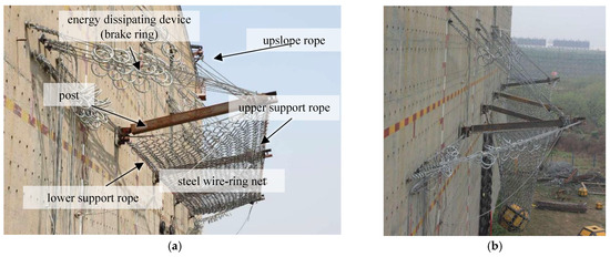
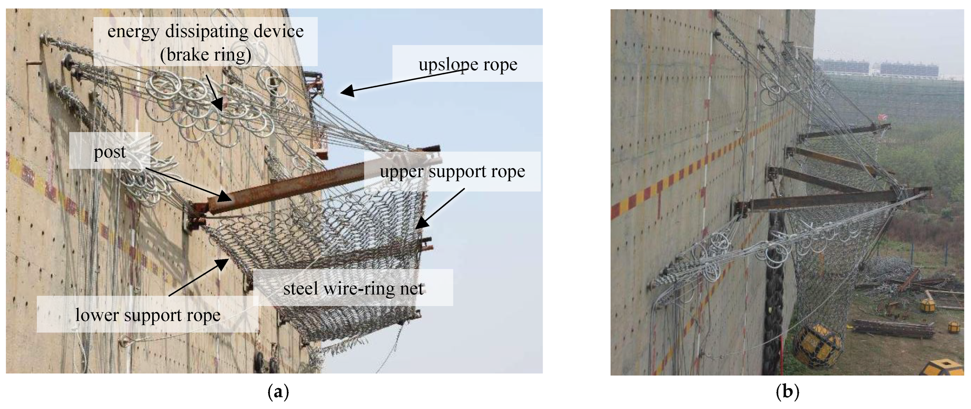
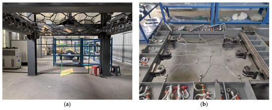
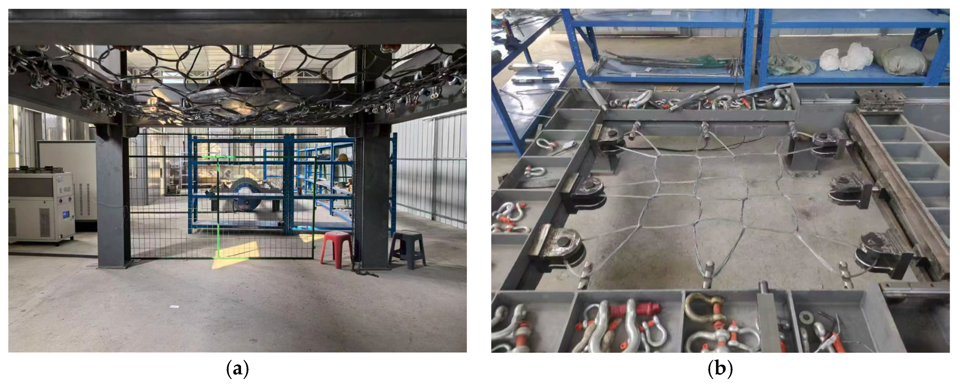
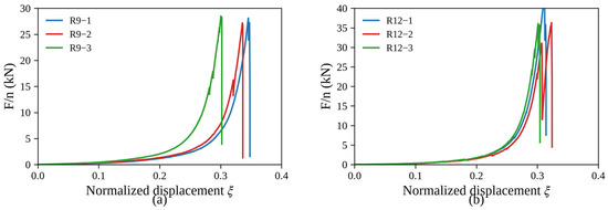
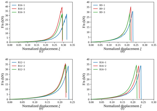
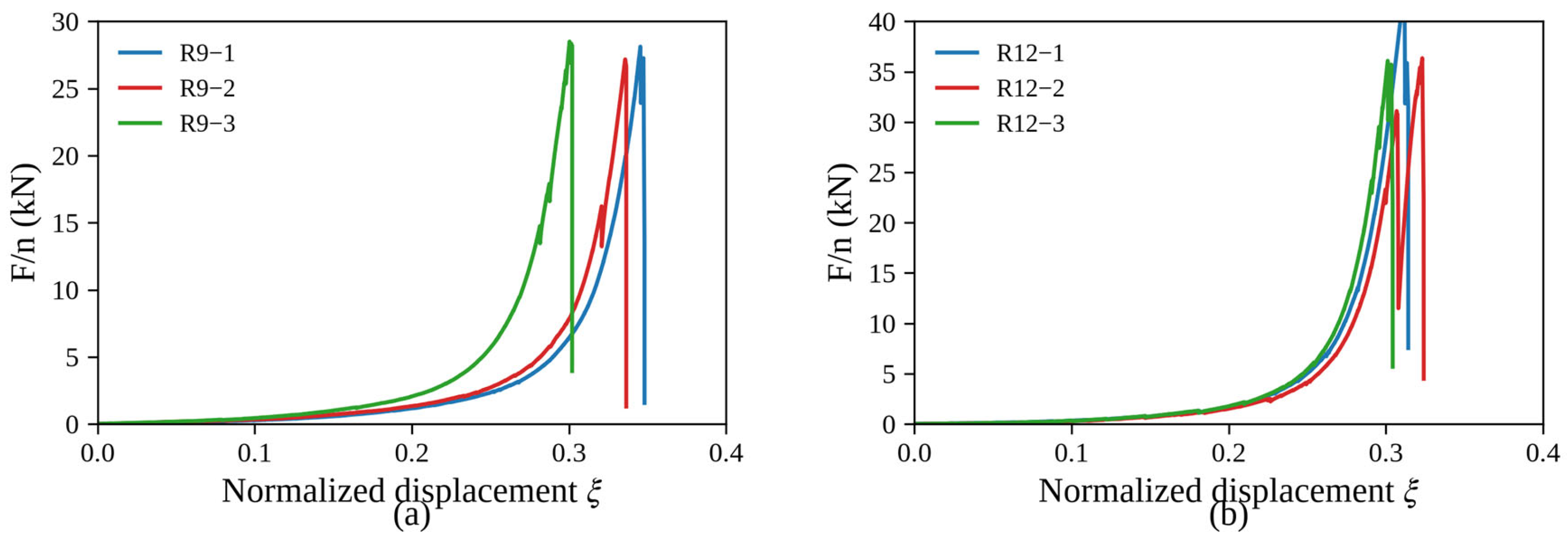
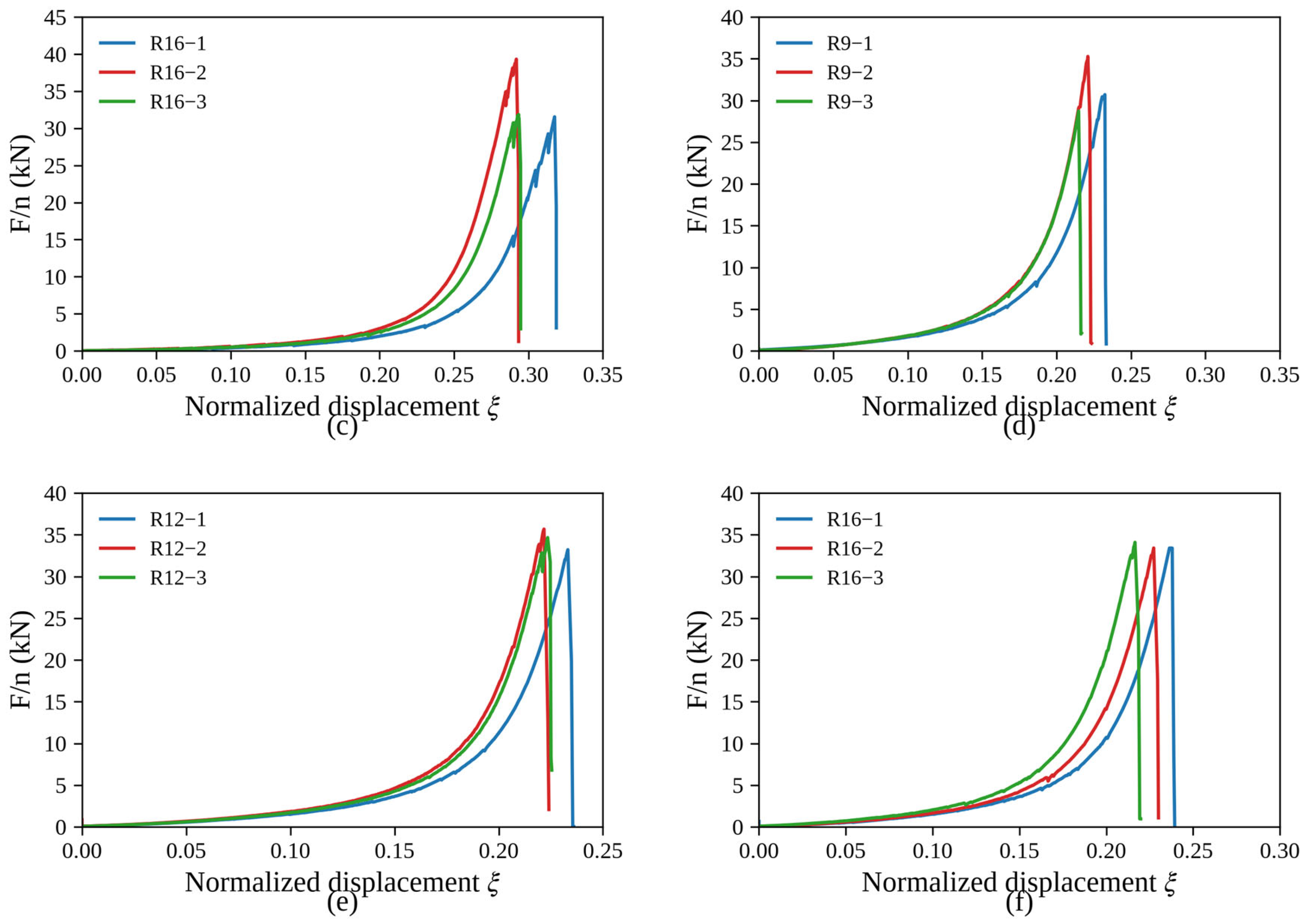
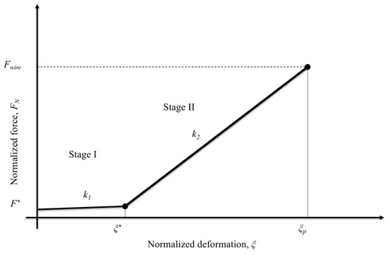
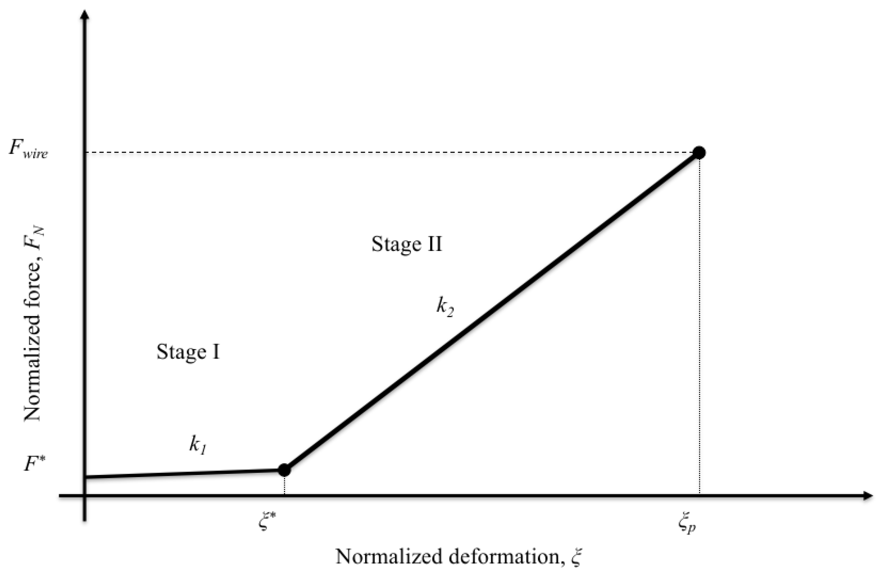
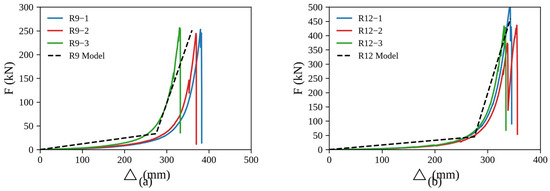
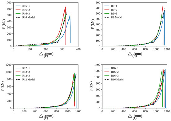
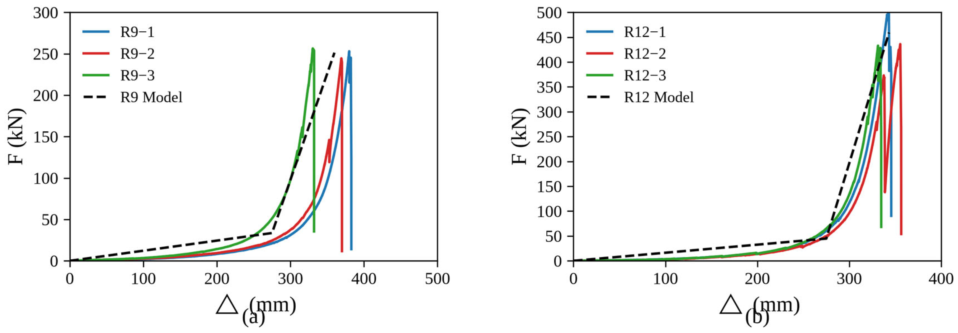
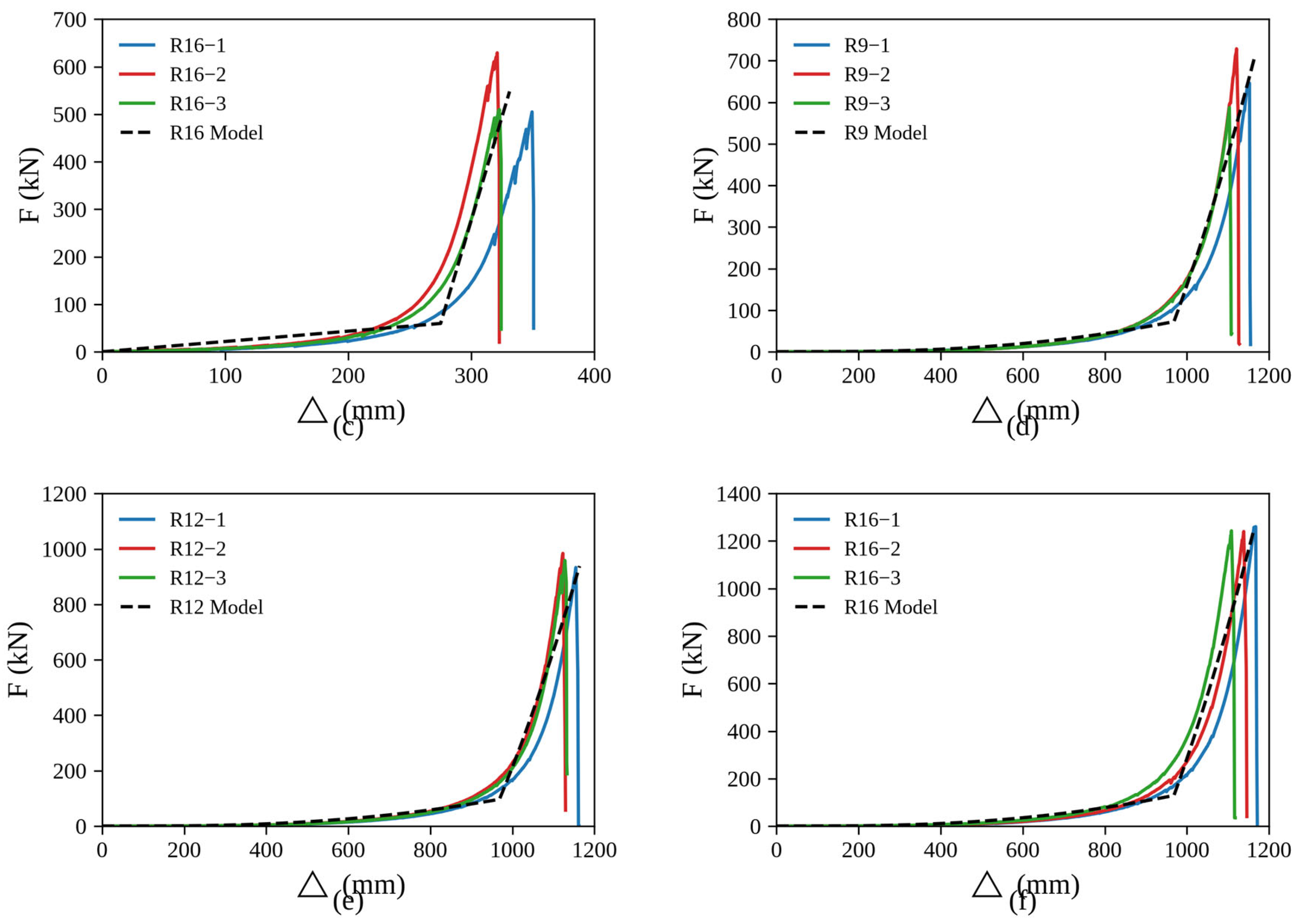
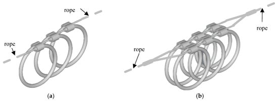
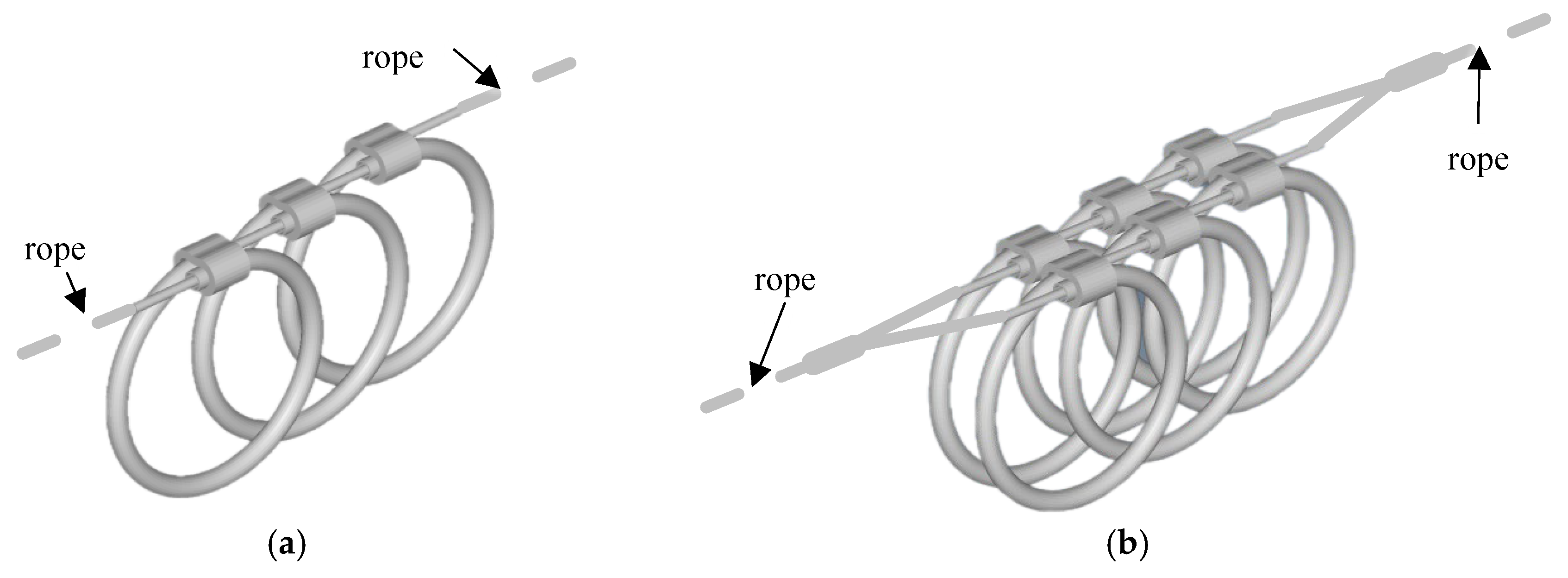
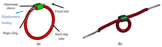
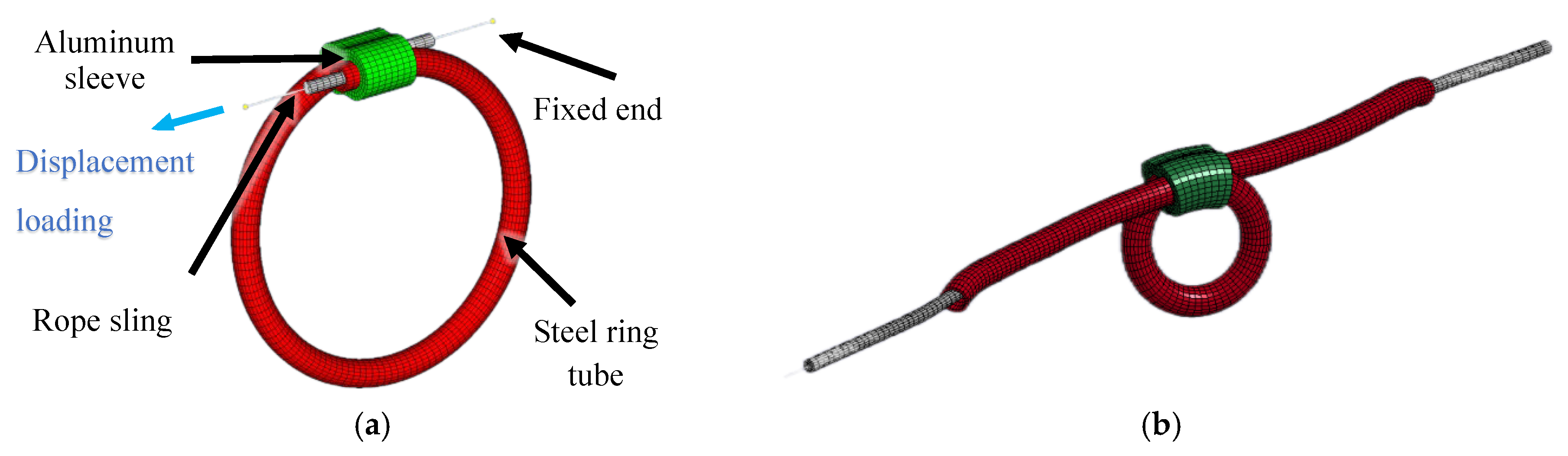
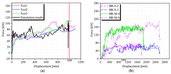
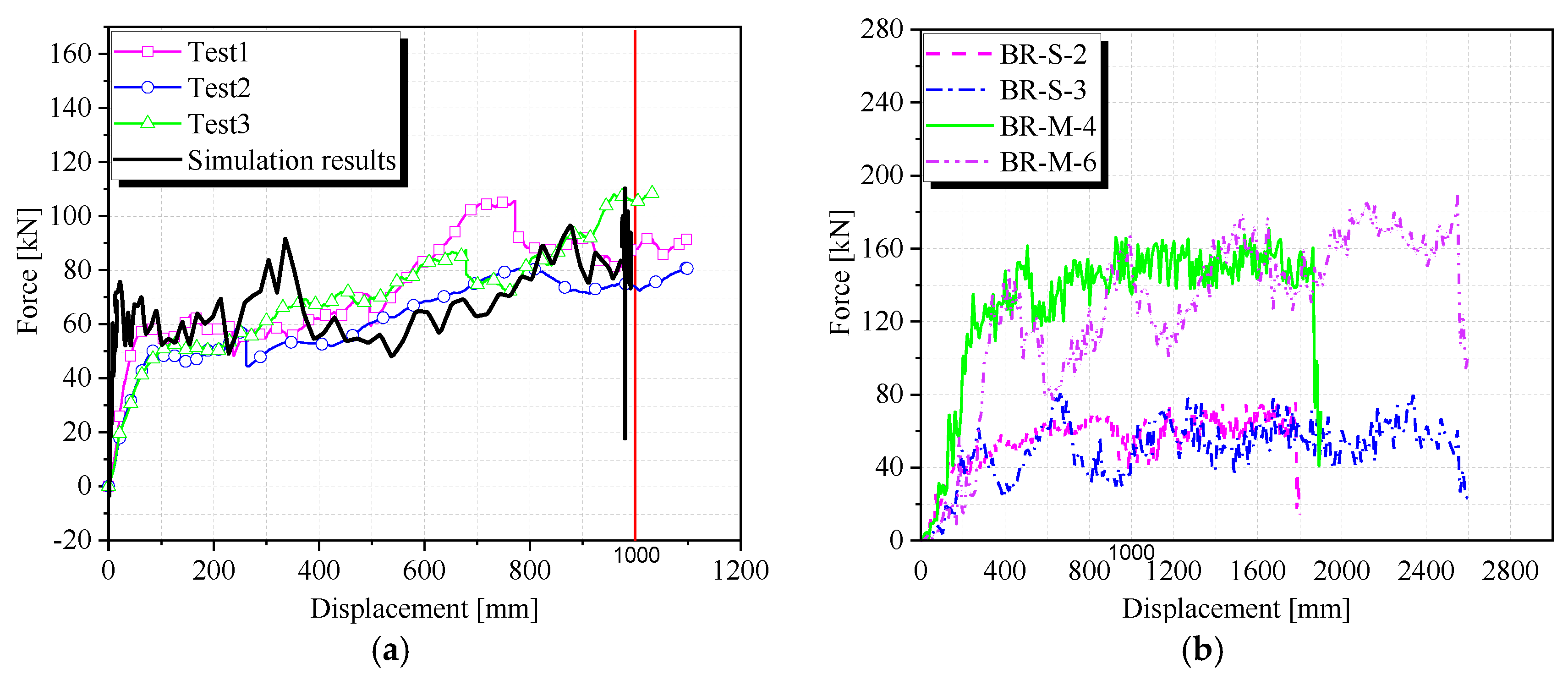
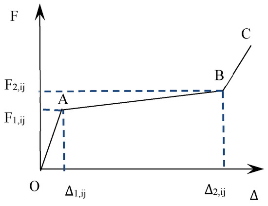
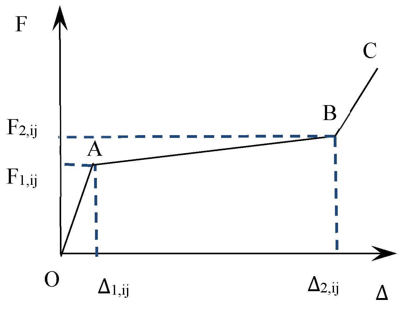
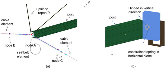
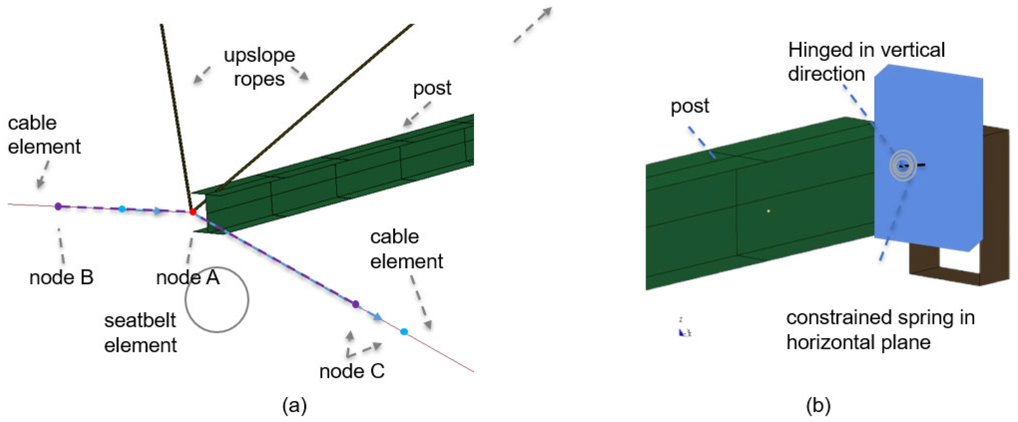
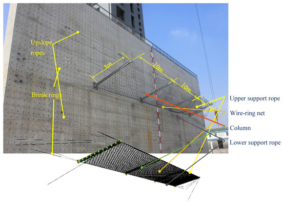
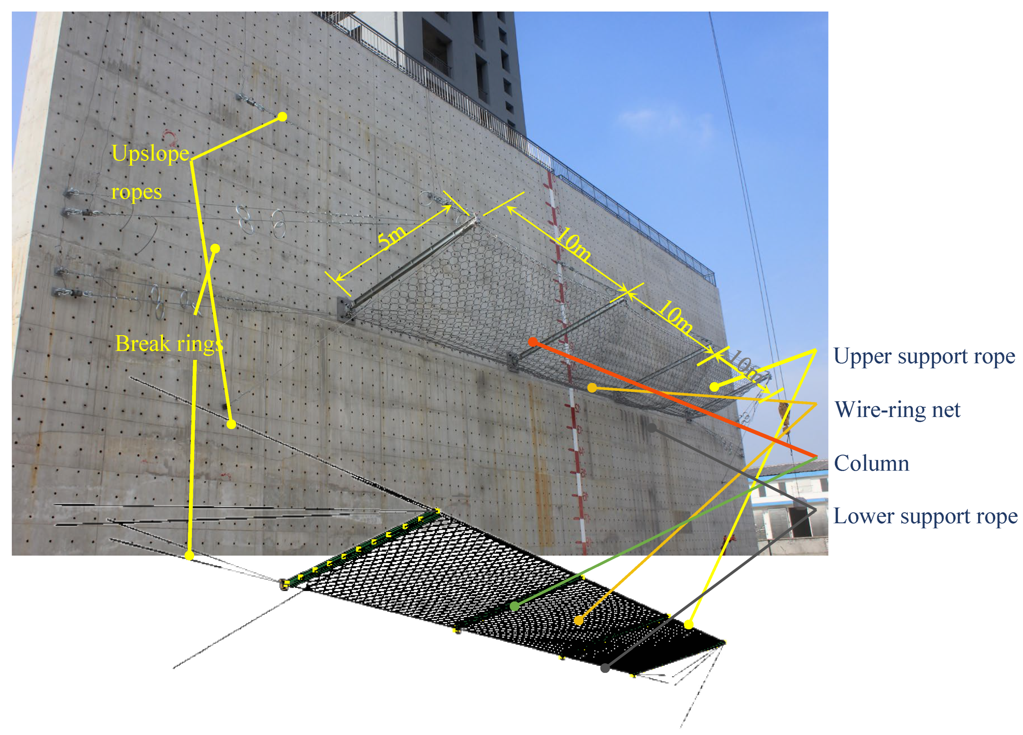
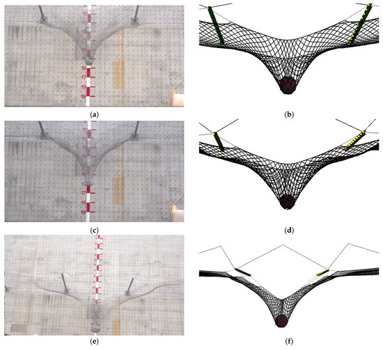
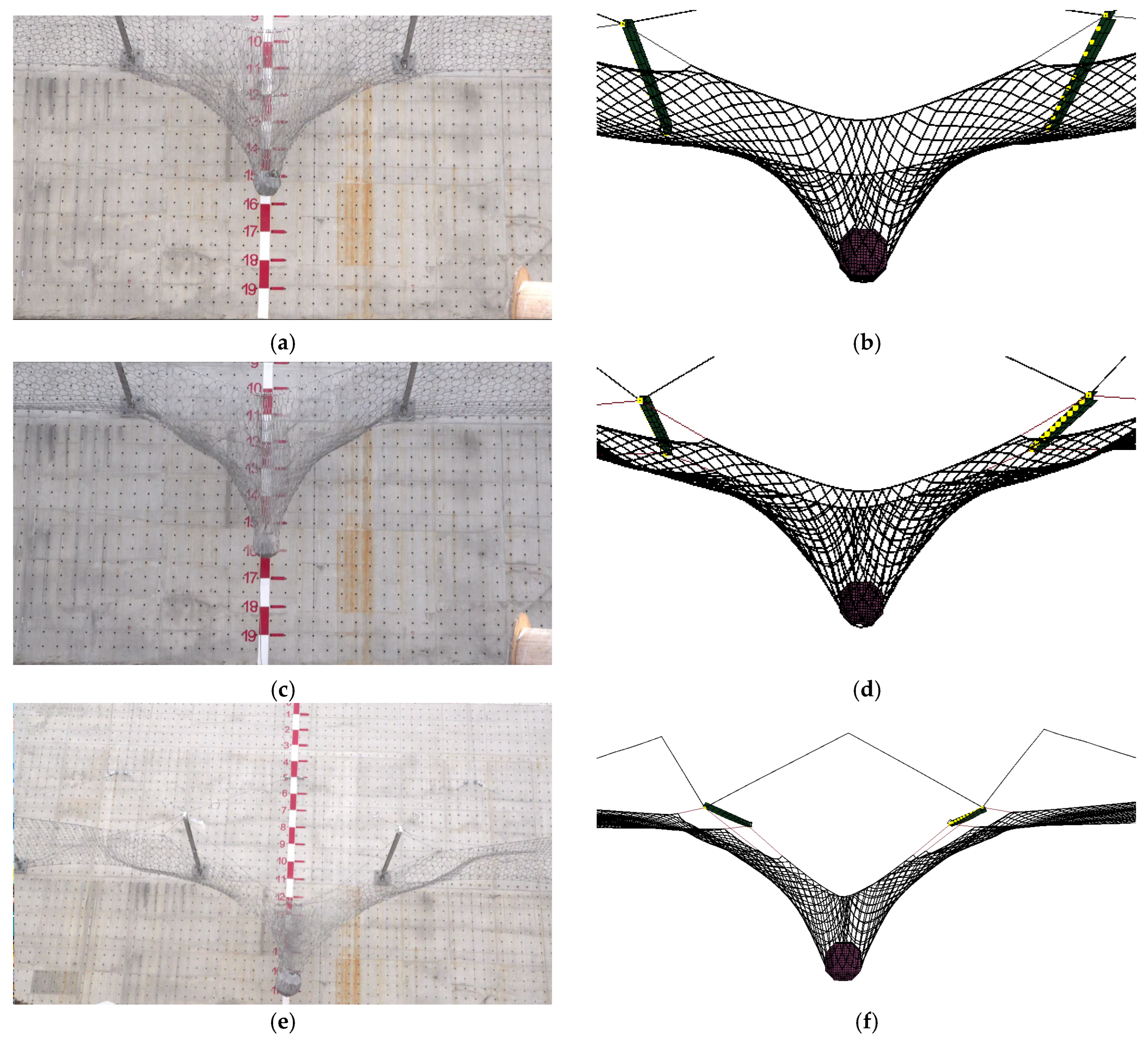
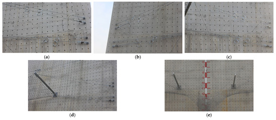
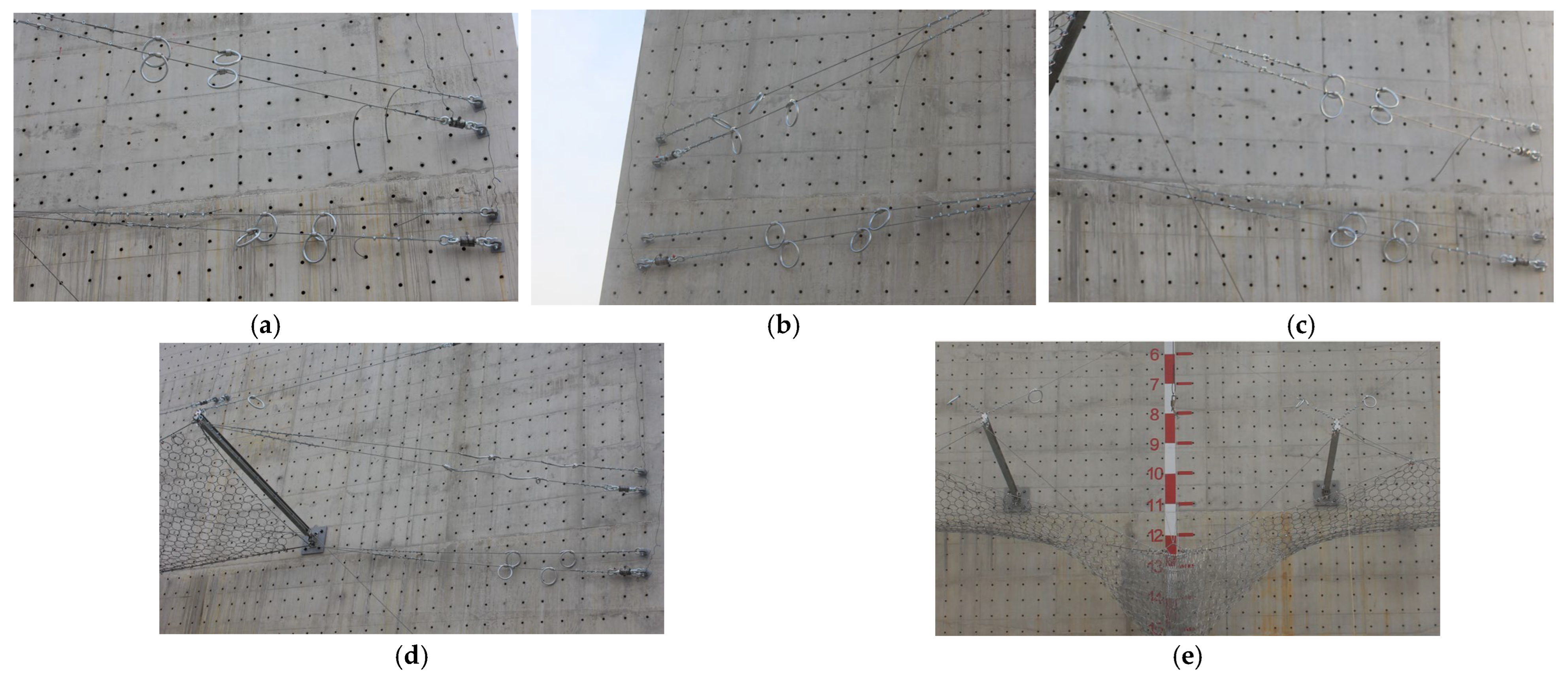
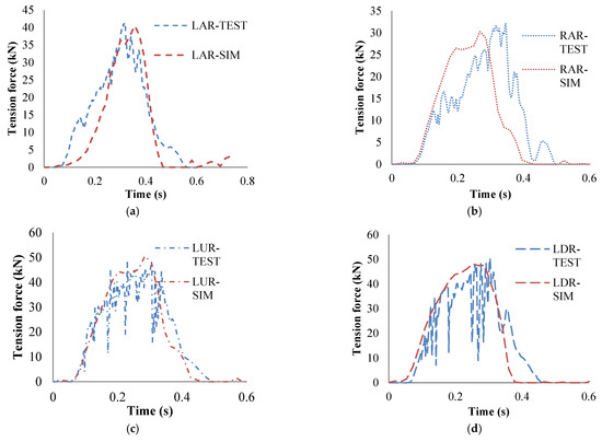
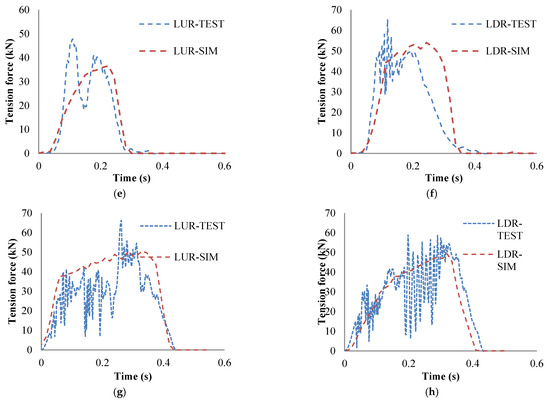
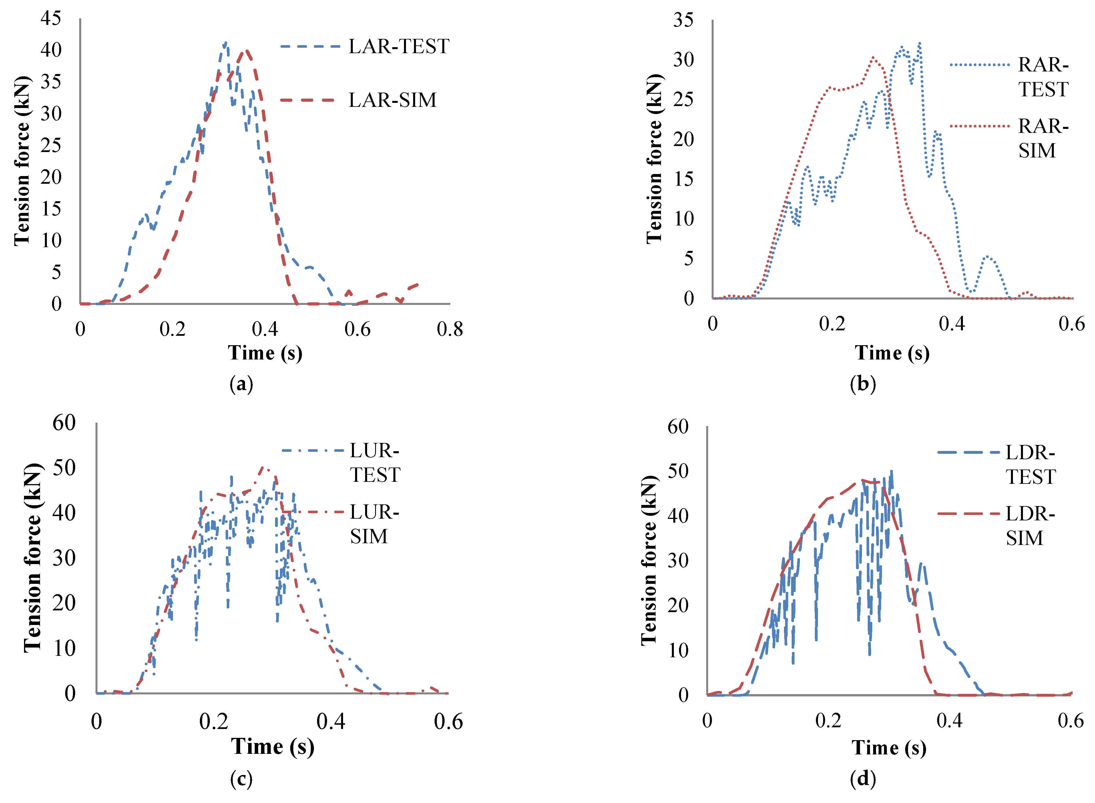
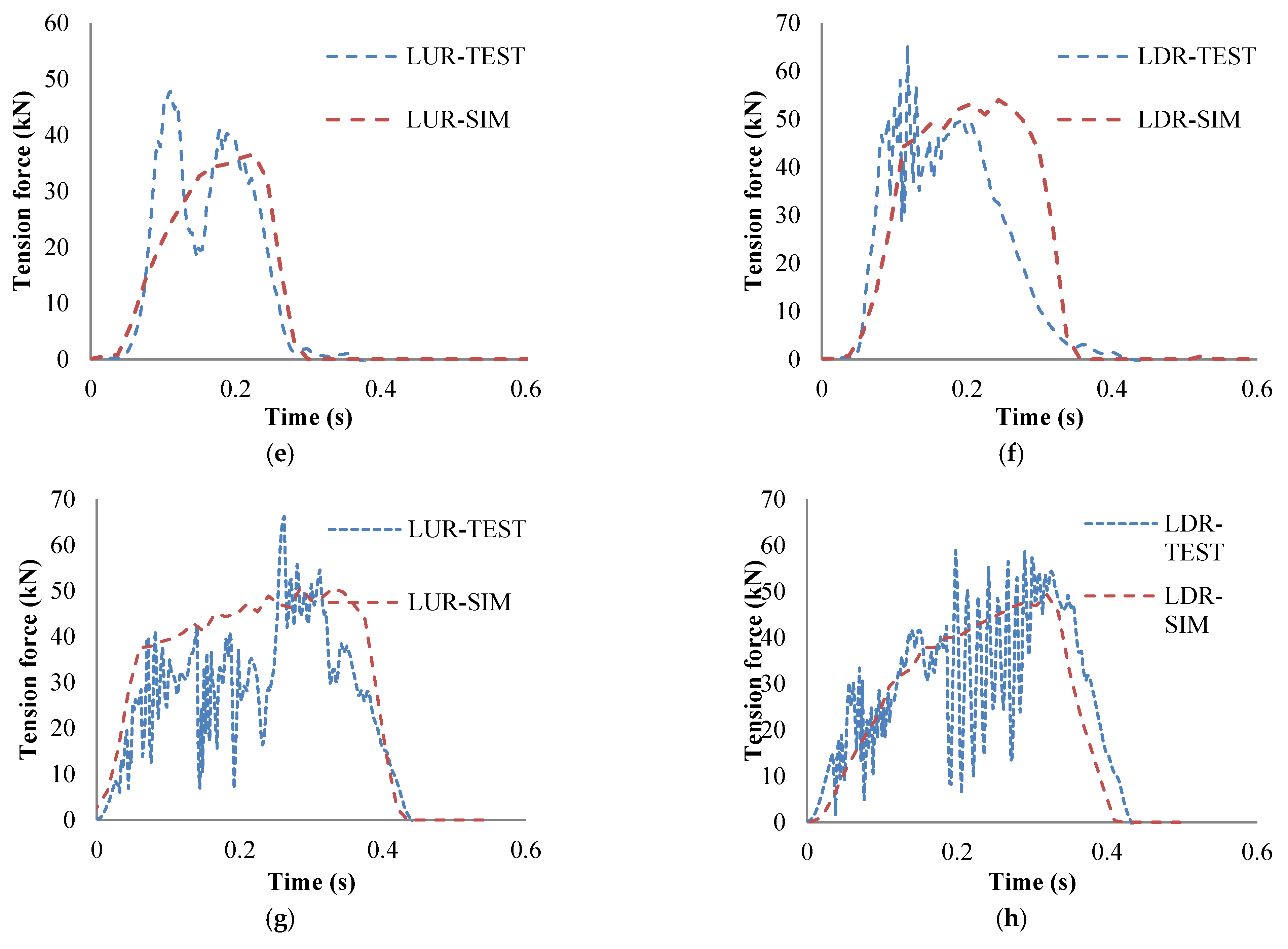
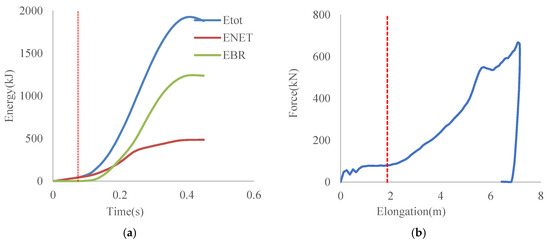
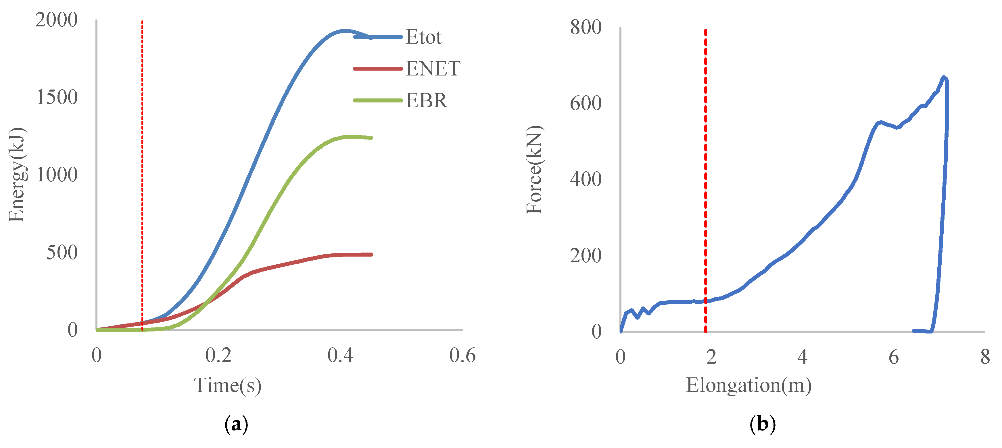
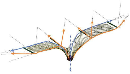
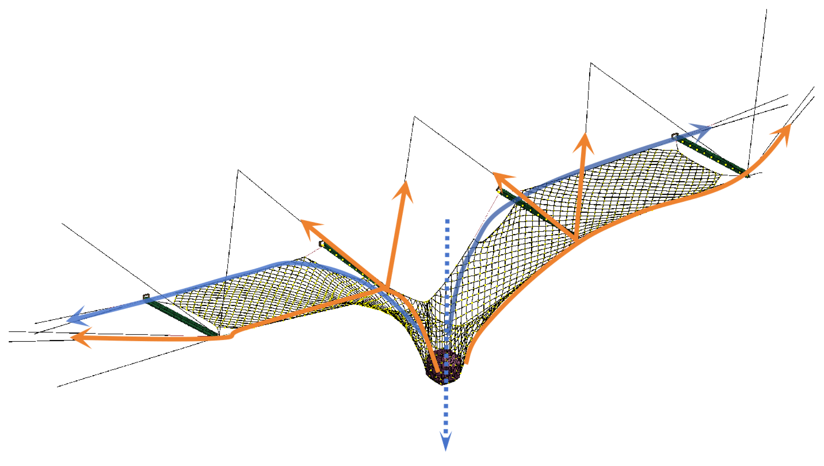
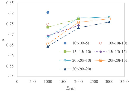
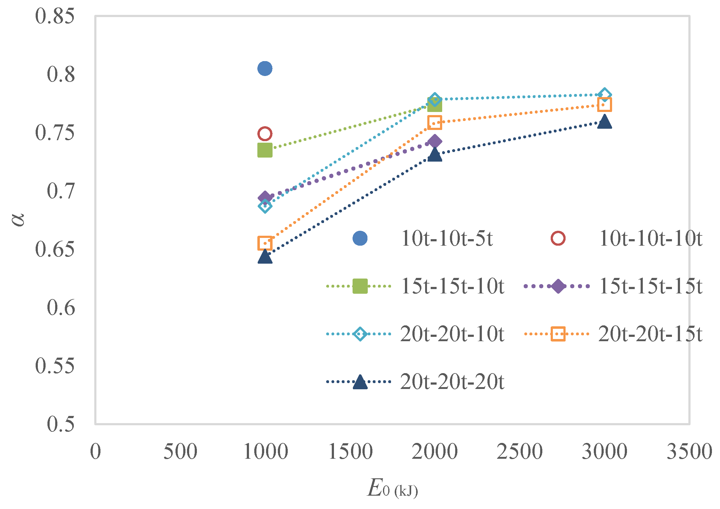
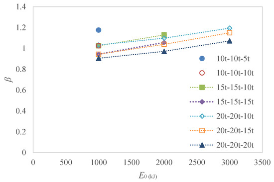
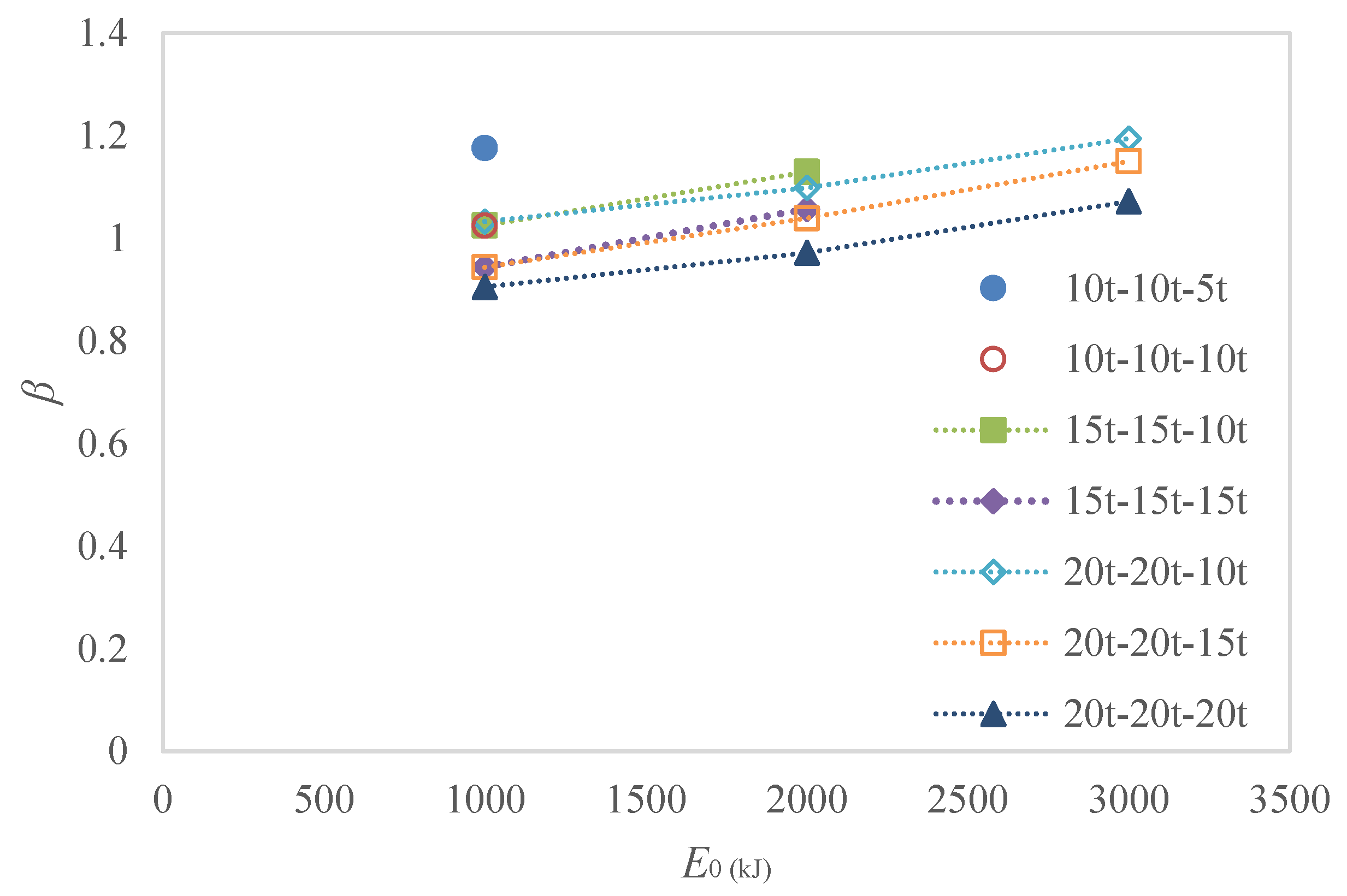
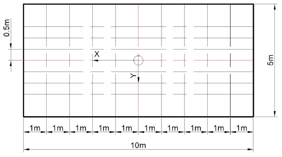
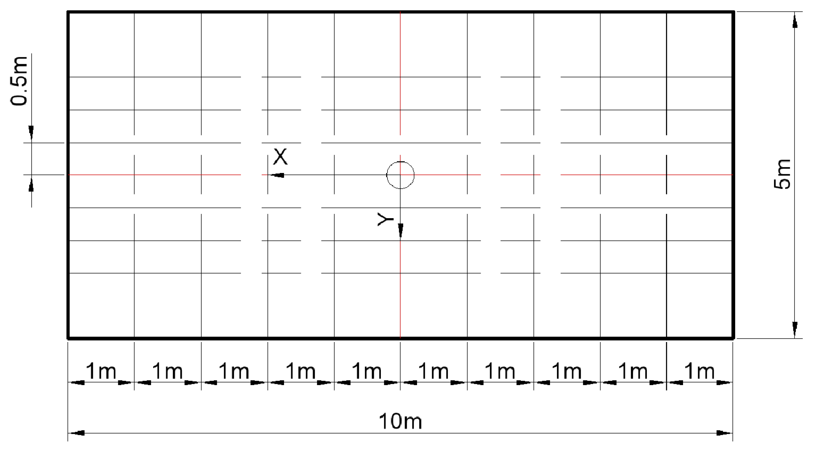
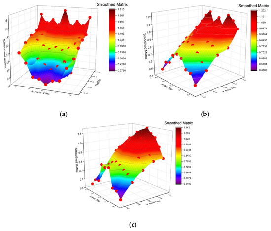
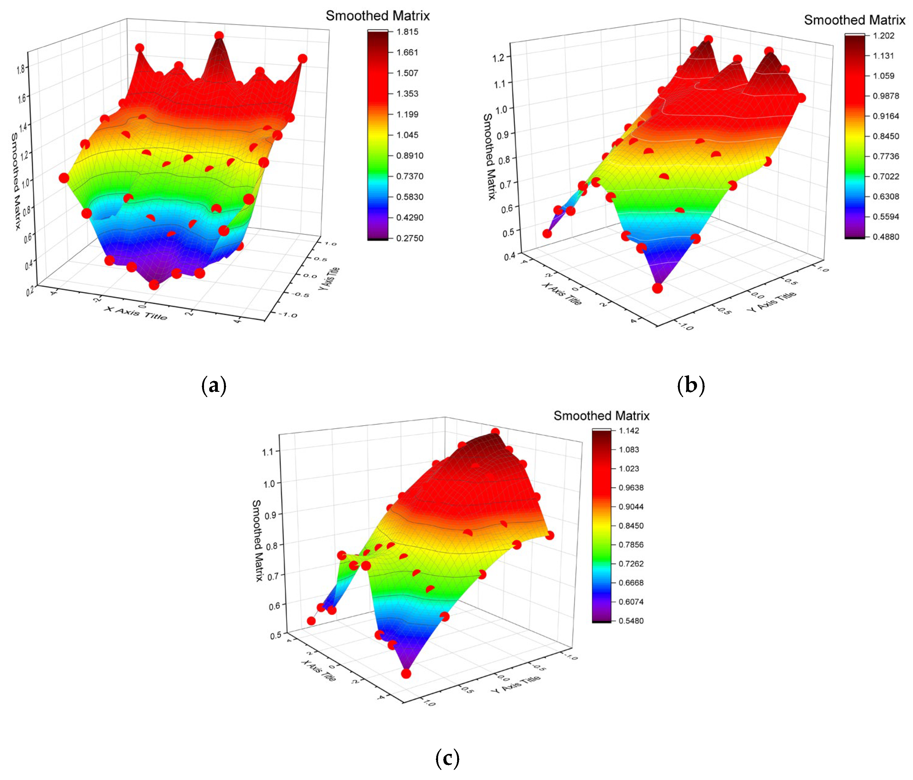





Disclaimer/Publisher’s Note: The statements, opinions and data contained in all publications are solely those of the individual author(s) and contributor(s) and not of MDPI and/or the editor(s). MDPI and/or the editor(s) disclaim responsibility for any injury to people or property resulting from any ideas, methods, instructions or products referred to in the content. |
© 2026 by the authors. Licensee MDPI, Basel, Switzerland. This article is an open access article distributed under the terms and conditions of the Creative Commons Attribution (CC BY) license.