


Abstract
With the gradual depletion of high-quality and readily mineable coal resources, recovering coal beneath buildings while controlling surface subsidence is important for sustainable resource development and protection of surface structures. Using the 11205 working face of Taitou Coal Mine as a case study, a three-roadway continuous mining and backfilling scheme combined with compact backfilling by grout injection into bags was proposed, and Fast Lagrangian Analysis of Continua in 3 Dimensions (FLAC3D) simulations were performed to evaluate the effects of branch-roadway width and backfilling ratio. At a 97% backfilling ratio, increasing branch-roadway width from 4 to 6 m increased maximum roof subsidence from 40.41 to 65.21 mm, maximum horizontal displacement from 1.220 to 2.174 mm, and the stress concentration factor from 2.62 to 2.96. At a 5 m width, increasing the backfilling ratio from 83% to 89% reduced maximum roof subsidence by 14.4%, whereas increasing it from 90% to 97% reduced subsidence by only 0.35 mm, indicating a pronounced diminishing-return response with markedly reduced sensitivity around 89–90%. Considering both subsidence control and construction efficiency, a branch-roadway width of 5 m and a backfilling ratio of 95% were selected. Field monitoring showed maximum strike and dip subsidence of 16.60 and 17.93 mm within 30 days. These results provide a reference for subsidence-controlled coal recovery beneath buildings under similar conditions.
1. Introduction
Coal resource continuity is fundamental to the long-term safe operation and sustainable development of coal mines. With the gradual depletion of high-quality and readily mineable coal resources, the recovery of coal reserves under the “three-under” conditions—namely, beneath buildings, railways, and water bodies—has become an increasingly important issue affecting the sustainable operation of coal mines. Among coal resources constrained by the “three-under” conditions, coal reserves beneath buildings account for a relatively large proportion and can exceed 90% in some mining areas. Their safe and efficient recovery is therefore of considerable importance for releasing sterilized coal resources, alleviating pressure on mine production continuity, and supporting sustainable coal production [1,2]. At present, the principal approaches for managing and recovering coal resources beneath buildings include leaving protective coal pillars, relocating surface structures, strip mining, and backfilling mining. However, these methods are still associated with limitations such as substantial resource loss, high relocation costs, limited recovery ratios, and difficulties in coordinating mining and backfilling operations and achieving effective roof contact [3,4,5]. Therefore, improving the recovery of coal resources beneath buildings while controlling overburden movement and surface subsidence is important not only for mine safety and production continuity, but also for land and building protection, the resource utilization of solid waste, and the mitigation of environmental disturbance in mining areas. It has thus become an important research direction for the green and sustainable development of coal resources.
Research on compact backfilling mining has focused on overburden movement control, backfill strength design, mining and backfilling equipment, and the resource utilization of solid waste. In terms of subsidence-control mechanisms, studies have investigated elastic-foundation thin-plate models, laminated-plate models, equivalent mining height, principles for controlling overburden deformation, and multi-horizon coordinated control, revealing the mechanisms governing overburden movement and surface subsidence under compact backfilling conditions [6,7,8].
With respect to backfill strength design, studies have examined alternating load-bearing between coal and backfill bodies, lateral pressure acting on roadway backfill, and the determination of uniaxial compressive strength, providing a basis for evaluating backfill load-bearing capacity [9,10,11]. Recent studies have further investigated the damage evolution and constitutive behavior of cemented backfill materials, providing additional insight into their deformation and failure characteristics under loading [12].
In terms of mining and backfilling equipment, technologies such as automated backfilling systems, roadside backfilling and gob-side entry retaining have improved the mechanization level of backfilling operations and enhanced roadway surrounding-rock control [13,14,15]. Regarding solid-waste utilization, all-solid-waste backfilling and coal-mine solid-waste backfilling technologies have promoted the underground disposal and resource utilization of coal gangue, fly ash, and other coal-based solid wastes [16,17,18].
Coordination between coal extraction and backfilling is a key factor affecting the efficiency and field applicability of compact backfilling mining. Conventional sequential mining–backfilling or serial mining–backfilling modes are constrained by available backfilling space, backfilling duration, and the early-age strength development of backfill materials, which can result in mutual interference and waiting between mining and backfilling operations and consequently reduce the continuity of working-face advance. To improve mining–backfilling coordination, parallel mining and backfilling as well as continuous mining and backfilling methods have been proposed [19,20].
Among them, the “one mining roadway–one backfilling roadway–one standby roadway” three-roadway continuous mining and backfilling mode arranges mining, backfilling, and standby operations in different branch roadways. Through the rolling conversion of these three operational spaces, mining and backfilling activities can be spatially separated and continuously coordinated, thereby reducing operational waiting while improving the flexibility of process transitions [21]. When further combined with paired branch roadways, interval skip mining, and timely backfilling, the mining disturbance can be confined to the branch-roadway scale, while the alternating support provided by unmined coal and hardened backfill can limit continuous roof exposure [22,23,24]. By contrast, wall-type continuous mining and backfilling, shortwall continuous mining and backfilling, and continuous excavation–continuous backfilling technologies mainly achieve continuous advance through zoned layouts, staggered extraction, and spatial decoupling of mining and backfilling activities [25,26,27].
Overall, previous studies have established a relatively systematic theoretical and engineering foundation in the areas of overburden movement control, backfill load-bearing behavior, mining and backfilling equipment, and mining–backfilling organization. Although considerable attention has been given to branch-roadway layout, interval extraction, and stage-dependent load-bearing under continuous mining and backfilling conditions, the effects of branch-roadway width and backfilling ratio on overburden response and surface subsidence, as well as their reasonable matching relationship, under the organizational mode of “paired branch roadways, interval skip mining, and mining followed by backfilling” remain insufficiently understood. Therefore, taking the 11205 working face in the No. 2 coal seam of Taitou Coal Mine as the engineering background, this study proposes a fully mechanized compact backfilling scheme based on three-roadway continuous mining and backfilling. Numerical simulations are conducted to quantify the effects of branch-roadway width and backfilling ratio on overburden response and surface subsidence, clarify their matching relationship under the proposed mining–backfilling scheme, and identify a suitable parameter combination. The engineering performance of the selected parameters is further evaluated using field measurements of surface subsidence. The study aims to provide a technical basis for the safe recovery of coal resources beneath buildings, low-disturbance control of surface deformation, and the utilization of coal-based solid wastes in backfilling, while offering engineering guidance for sustainable mining practices that coordinate resource recovery, operational safety, environmental protection, and production efficiency in similar mines.
2. Materials and Methods
2.1. Overview of the Study Site
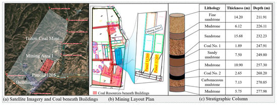
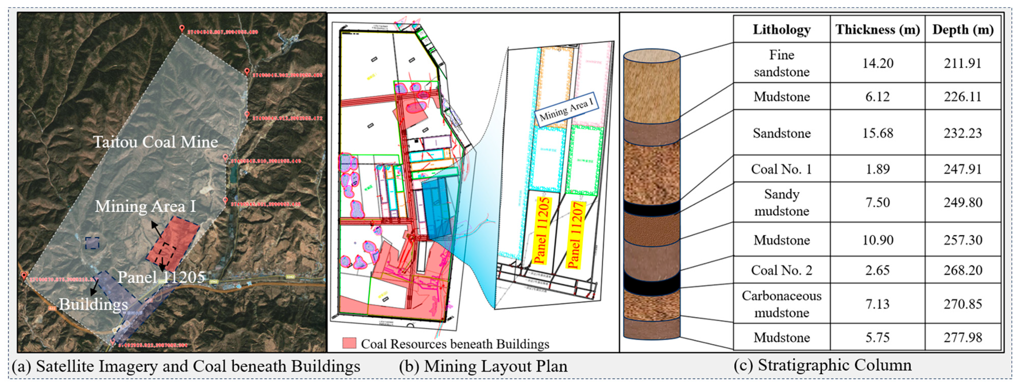
The mine operated by Shanxi Xiangning Coking Coal Group Taitou Coal and Coke Co., Ltd. is located in the southeastern part of the Hedong Coalfield. It has an approved production capacity of 1.5 Mt/a and a mine-field area of 18.0846 km2, with remaining coal resources and reserves of 117 Mt and remaining recoverable reserves of 44 Mt. The principal mined seams are Coal Seams Nos. 1 and 2. Coal Seam No. 2 occurs at an average depth of approximately 268 m and ranges in thickness from 1.68 to 3.19 m, with an average of 2.65 m. It is a stable coal seam that is mineable throughout the area and covers a total area of 1.5606 km2. The study area layout is shown in Figure 1.
Figure 1.
Mining layout and stratigraphic characteristics of the study area.
In Mining Area I of Coal Seam No. 2, extraction has been completed except for the protective coal pillars beneath the village, whereas the protective coal pillars in Mining Areas II and III are surrounded by unmined coal. The total coal reserves beneath buildings and structures are approximately 5.7152 Mt, of which approximately 5.1437 Mt are recoverable, as shown in Table 1. To recover these resources, the 11205 trial backfill mining face is planned in Coal Seam No. 2, using three-roadway continuous mining and backfilling combined with fully mechanized compact backfilling. The remaining unmined coal block at the 11205 working face extends 430 m along strike and is 160 m wide. The lithological parameters of the mine strata are listed in Table 2. The mechanical parameters of the coal and rock strata were determined based on mine geological data and geomechanical test results, with appropriate adjustments considering lithological characteristics and rock-mass scale effects to obtain the equivalent rock-mass parameters used in the numerical model. The mechanical parameters of the backfill in Table 2 were selected with reference to laboratory mechanical tests and parameter ranges reported in previous numerical studies of coal-mine backfilling, with the cohesion and friction angle set to 1.0 MPa and 28°, respectively [28]. Taking this working face as the study site, this study develops the three-roadway continuous mining and backfilling scheme, numerically evaluates suitable combinations of branch-roadway width and backfilling ratio, and verifies their effectiveness through field monitoring of surface subsidence.
Table 1.
Coal reserves beneath buildings and structures in Coal Seam No. 2.
Table 2.
Lithological parameters of the strata.
2.2. Three-Roadway Continuous Mining and Backfilling Scheme
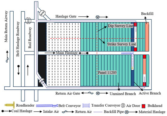
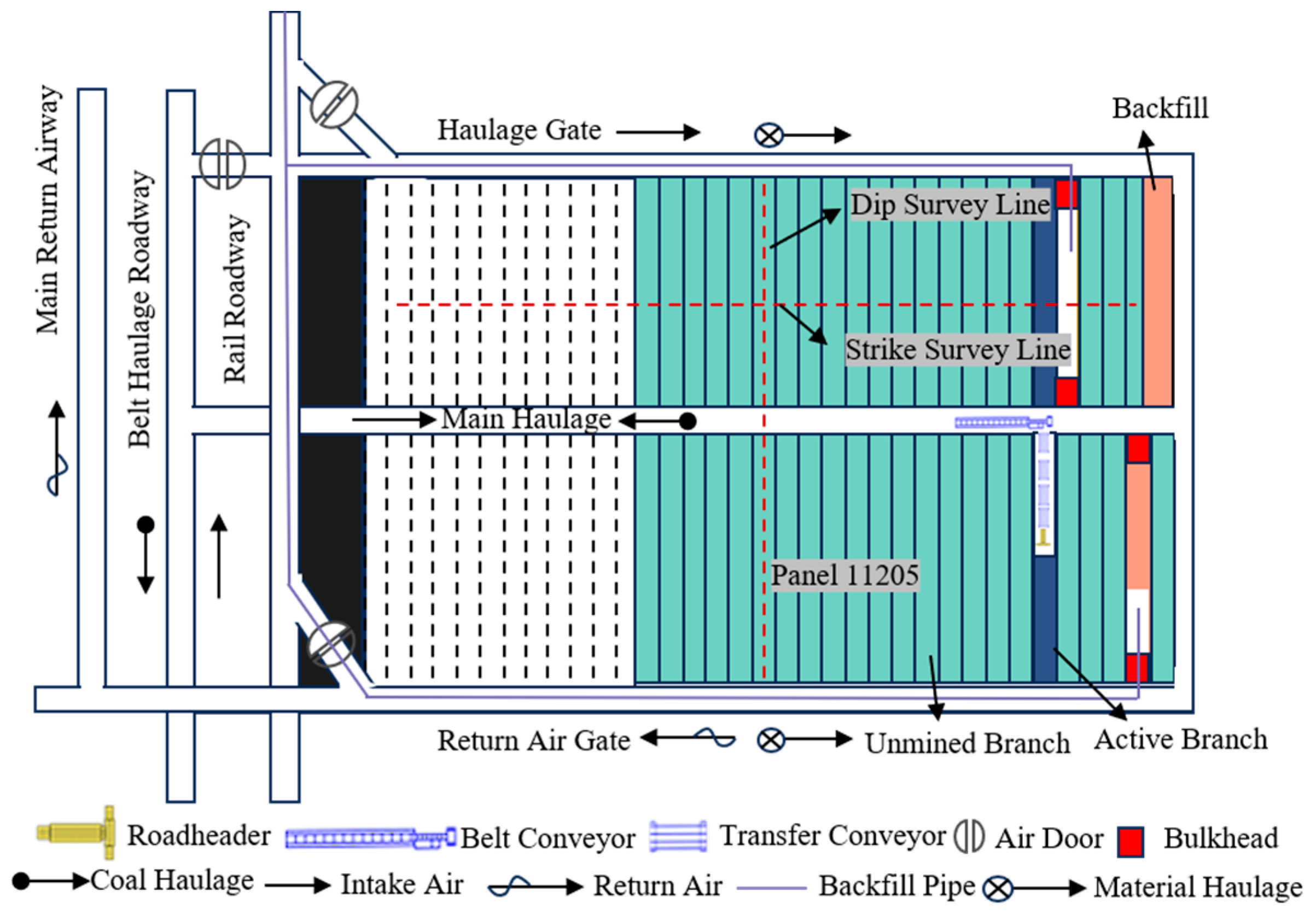
A fully mechanized backfill mining scheme is proposed for the coal resources beneath buildings within the 11205 working face, using three-roadway continuous mining and backfilling as the operational arrangement and compact backfilling by grout injection into bags as the core technology. Compact backfilling is implemented promptly after extraction in each branch roadway. By forming load-bearing backfill bodies with limited compressive deformation, this technique enables the backfill and unmined coal to jointly support the overlying strata, thereby controlling roof subsidence, overburden movement, and surface subsidence. As shown in Figure 2, the backfill mining system comprises coal extraction, haulage, ventilation, and backfilling subsystems. Extracted coal is transferred by haulage equipment within the branch roadways to the central main haulage roadway for onward transport. Following extraction, the branch roadways are sealed and backfilled by injecting grout through backfilling pipelines. The haulage gate and central main haulage roadway serve as intake airways, while the return air gate provides the return airflow. Together, these subsystems form an integrated operational system linking branch-roadway excavation and coal extraction, haulage, roadway sealing, and grout backfilling.
Figure 2.
System layout of the 11205 working face.
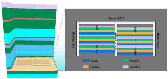
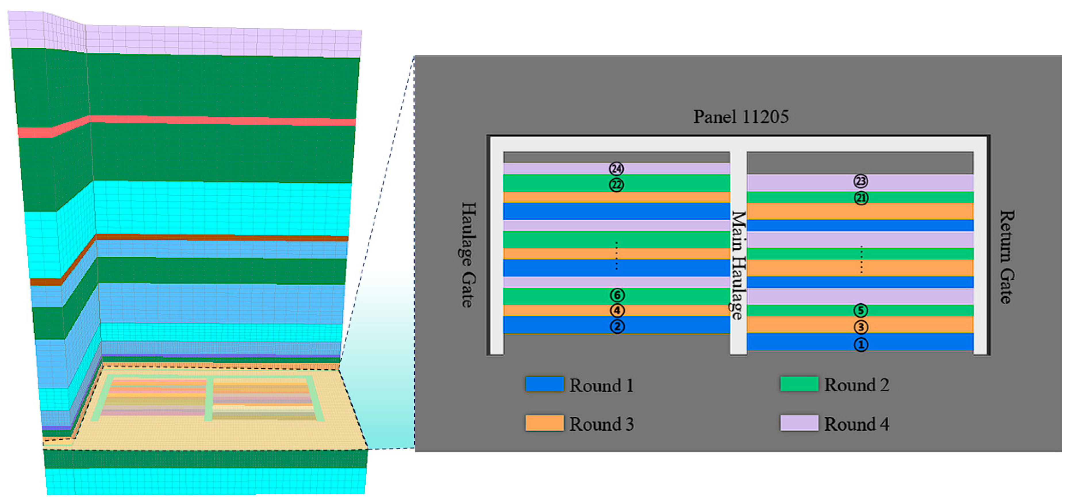
Based on the spatial conditions of the working face, the branch roadways are arranged perpendicular to the central main haulage roadway. Considering the operating space required for the roadheader, coal haulage conditions, and branch-roadway development requirements, a preliminary branch-roadway width of 5 m is selected, with each branch roadway extending approximately 80 m on either side of the central main haulage roadway. Two adjacent branch roadways form a mining–backfilling unit. A roadheader–scraper conveyor configuration is adopted to accommodate branch-roadway excavation and coal extraction while ensuring continuous coal haulage. Mining and backfilling follow a four-round staggered extraction sequence featuring paired branch roadways, extraction at intervals, and backfilling behind the advancing mining operations. Once extraction in a branch-roadway pair is completed, the roadways are promptly sealed and backfilled, while the other roadways remain unmined. The unmined coal and hardened backfill thus jointly support the roof, limiting the extensive unsupported roof spans that could otherwise result from successive extraction of adjacent branch roadways.
The extracted branch roadways are compactly backfilled by injecting grout into bags. The backfill mixture consists of coal gangue, fly ash, cement, and water. Based on the midpoints of the specified mix proportion ranges, coal gangue, fly ash, and cement account for 65%, 25%, and 10% of the total dry solids by mass, respectively, and the water-to-solids mass ratio is set to 0.40. The constituents are batched and mixed to produce a backfill slurry, which is then pumped through pipelines into backfill bags placed within the branch roadways. After hardening, the slurry forms load-bearing backfill bodies, ensuring compact filling and effective roof contact.
The backfilling ratio, η, is defined according to the volumetric compaction capacity of the backfill as
where εν,c denotes the designated compactive volumetric strain of the backfill. A higher backfilling ratio therefore corresponds to a lower volumetric compaction capacity of the backfill.
η = (1 − εν,c) × 100%
Branch-roadway width directly affects the unsupported roof span, the volume of the extracted space, and mining–backfilling efficiency, whereas the backfilling ratio governs the compressive deformation capacity of the backfill and, consequently, its effectiveness in restraining roof movement and supporting the roof. To evaluate the preliminary branch-roadway width, clarify the effects of branch-roadway width and backfilling ratio on overburden stability and surface subsidence, and identify a suitable combination of these parameters, numerical simulations under different branch-roadway widths and backfilling ratios are conducted using Fast Lagrangian Analysis of Continua in 3 Dimensions (FLAC3D, version 7.0) in the following sections.
2.3. Numerical Model
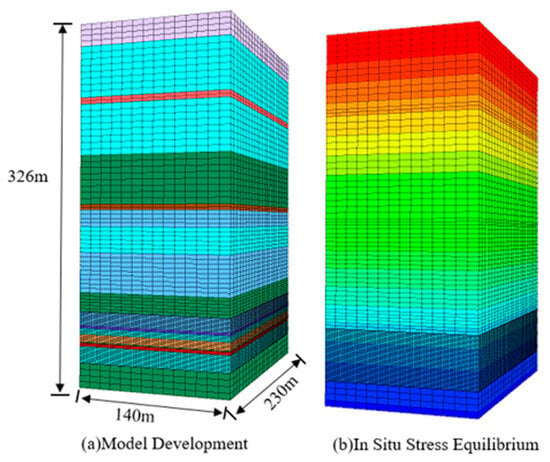
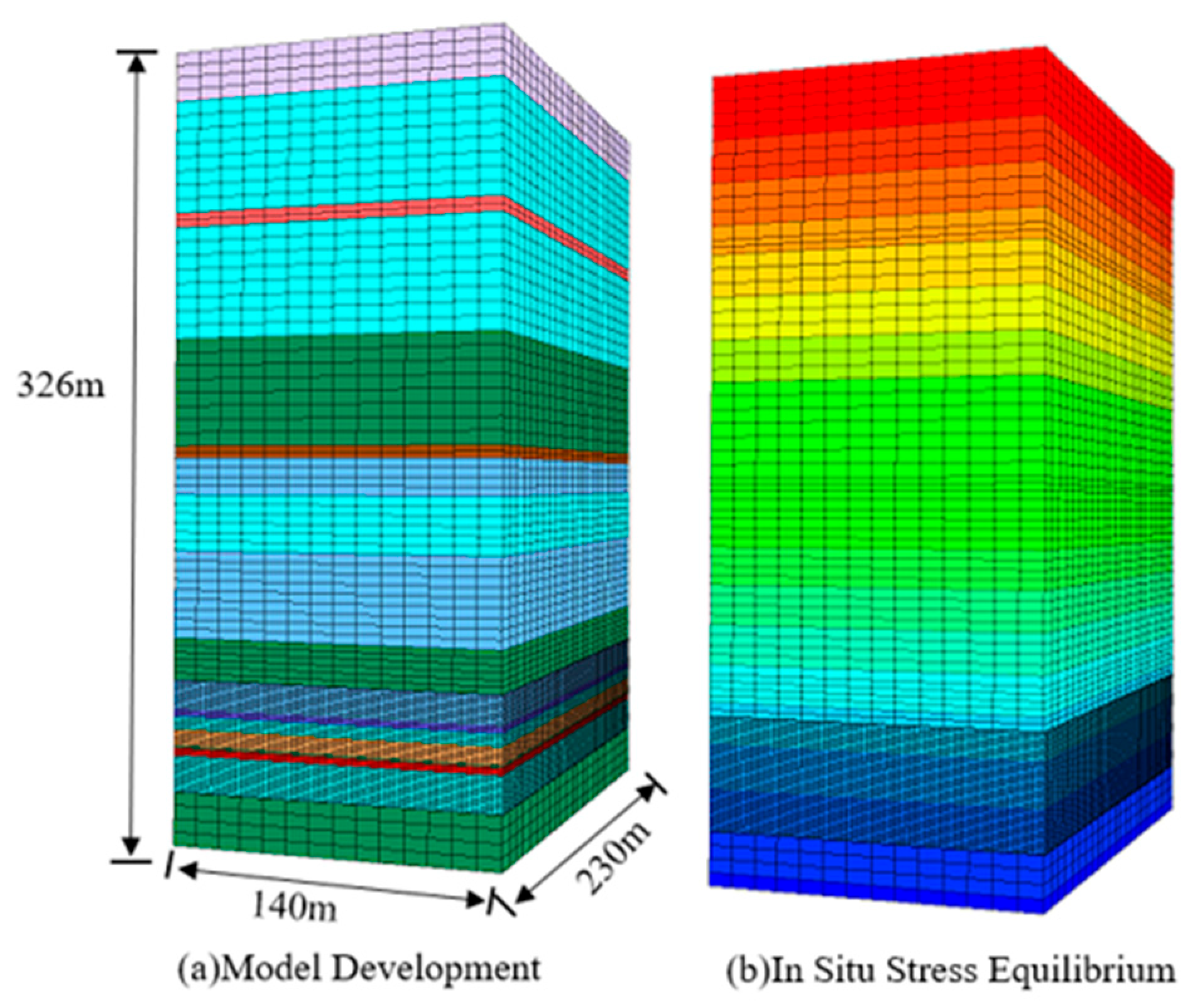
To investigate the effects of branch-roadway width and backfilling ratio on overburden stability and surface subsidence, a three-dimensional numerical model was developed using FLAC3D for the 11205 backfill mining face beneath buildings at the Taitou Coal Mine. The working face extracts Coal Seam No. 2, which has an average burial depth of approximately 268 m and an average thickness of 2.65 m. The working face is approximately 160 m wide and is divided into two wings by the central main haulage roadway, with branch roadways extending approximately 80 m into each wing. The model dimensions are 140 m × 230 m × 326 m, as shown in Figure 3. The upper boundary is free, vertical displacement is constrained at the bottom boundary, and displacement normal to each of the four lateral boundaries is constrained. To balance computational accuracy and efficiency, a refined mesh with horizontal zone dimensions of approximately 2 m × 2 m was adopted in the coal seam and the main mining–backfilling influence zone. The mesh was gradually coarsened to approximately 5 m × 5 m in the transition regions and to approximately 10 m × 10 m in the far field, resulting in approximately 4.0 × 10⁵ zones.
Figure 3.
Numerical model configuration and initial in situ stress equilibrium.
To evaluate the influence of mesh size on the numerical results, coarse, current, and fine mesh schemes were compared, as shown in Table 3. As the mesh size in the main mining–backfilling influence zone was refined from 3.0 m × 3.0 m to 2.0 m × 2.0 m, the relative differences in the main response indicators ranged from 1.46% to 3.94%. After further refinement to 1.5 m × 1.5 m, the differences decreased to 0.43–0.85%. These results indicate that the numerical results gradually converge with mesh refinement, and the adopted 2.0 m × 2.0 m mesh provides a reasonable balance between computational accuracy and efficiency.
Table 3.
Mesh sensitivity analysis results.
The coal and rock masses were represented by the Mohr–Coulomb constitutive model, while the backfill was represented by the double-yield constitutive model. In the numerical model, the mined-out space was initially fully occupied by the backfill, with no preset geometric gap between the backfill and the roof. Different backfilling ratios were represented by modifying the cap-pressure–plastic-volumetric-strain relationship of the double-yield model while keeping the other mechanical parameters unchanged. For each compaction control point, the corresponding plastic volumetric strain was determined as
where η is the backfilling ratio, is the plastic volumetric strain corresponding to the i th cap-pressure control point, and ξi is the normalized strain coordinate of the corresponding control point in the base compaction relationship.
For the double-yield model, the maximum bulk modulus and maximum shear modulus were 0.20 and 0.10 GPa, respectively; the cohesion was 1.0 MPa, the friction angle was 28°, the dilation angle was 0°, the tensile strength was 0.30 MPa, the initial cap pressure was 0.005 MPa, and the modulus multiplier was 5.0.
To quantify the degree of mining-induced stress concentration, the stress concentration factor, Kσ, is defined as
where συ,max is the maximum vertical stress after mining and backfilling, and συ0 is the initial vertical stress at the coal-seam level before mining. A larger Kσ indicates a stronger degree of mining-induced stress concentration.
Accordingly, the initial backfill height and roof-contact condition were identical for all backfilling-ratio cases, and the differences in equivalent mining height arose from the post-loading compression of the backfill rather than from an initial roof–backfill gap.
As shown in Figure 4, the model includes a haulage gate, a return air gate, a central main haulage roadway, and end crosscuts. A total of 24 staggered branch roadways are arranged on both sides of the central main haulage roadway, with each pair of adjacent branch roadways forming a mining–backfilling unit. The numerical simulation was performed according to the four-round staggered mining–backfilling sequence adopted in the field. In each round, the corresponding branch roadways were first excavated and subsequently backfilled before proceeding to the next round. Unmined coal or previously backfilled roadways were retained between different rounds to limit the extent of contiguous roof exposure and maintain support during successive mining–backfilling stages. The branch-roadway groups assigned to each round are listed in Table 4.
Figure 4.
Mining and backfilling sequence for four-round staggered extraction at the 11205 working face.
Table 4.
Branch-roadway grouping for four-round staggered extraction at the 11205 working face.
To investigate the effects of branch-roadway width and backfilling ratio on overburden stability and surface response, three branch-roadway widths (4, 5, and 6 m) and three backfilling ratios (90%, 95%, and 97%) were considered, yielding nine simulation scenarios covering all parameter combinations.
3. Results
3.1. Effect of Branch-Roadway Width
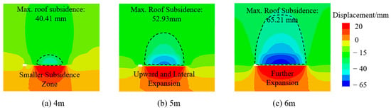
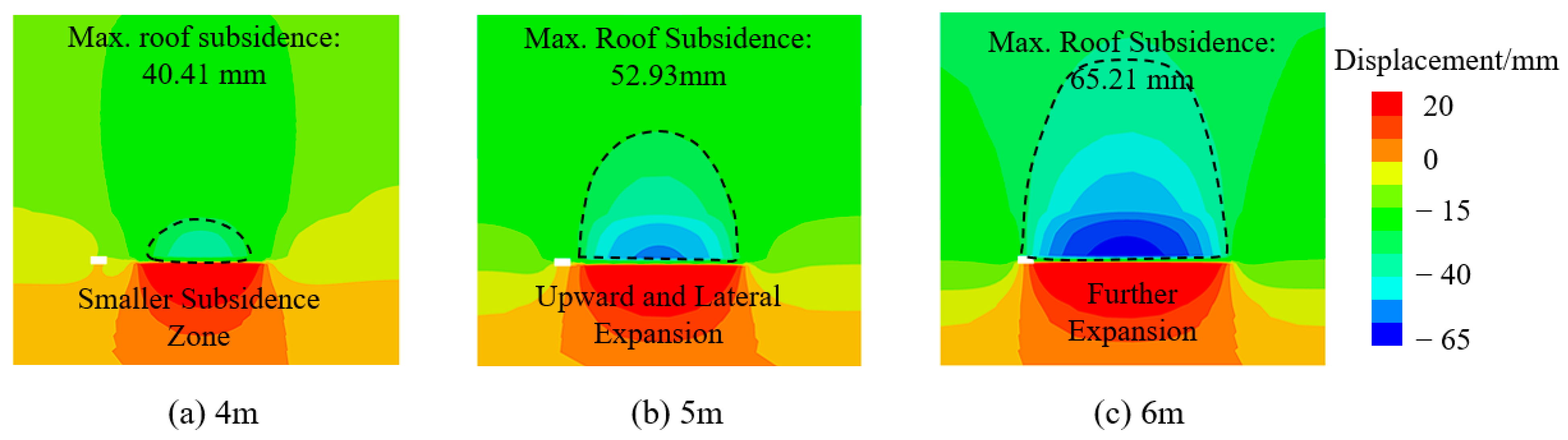
To investigate the effect of branch-roadway width on overburden movement at a backfilling ratio of 97%, a vertical cross-section through the middle of the branch roadways was extracted at y = 71 m in the model. The vertical displacement distributions for different branch-roadway widths are shown in Figure 5. For branch-roadway widths of 4, 5, and 6 m, the maximum roof subsidence was 40.41, 52.93, and 65.21 mm, respectively, with the latter two values representing increases of 30.9% and 61.4% relative to the 4 m scenario. Meanwhile, the zone of pronounced subsidence progressively extended upward and laterally. Increasing the branch-roadway width enlarged the effective unsupported roof span, intensified roof bending, and reduced the restraint exerted by the unmined coal on both sides and the backfill on the mining–backfilling area, thereby allowing deformation to propagate into higher overlying strata. These results indicate that, at a constant backfilling ratio, increasing branch-roadway width increases both the peak roof subsidence and the spatial extent of overburden disturbance.
Figure 5.
Roof subsidence for different branch-roadway widths at a backfilling ratio of 97%.
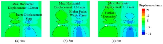
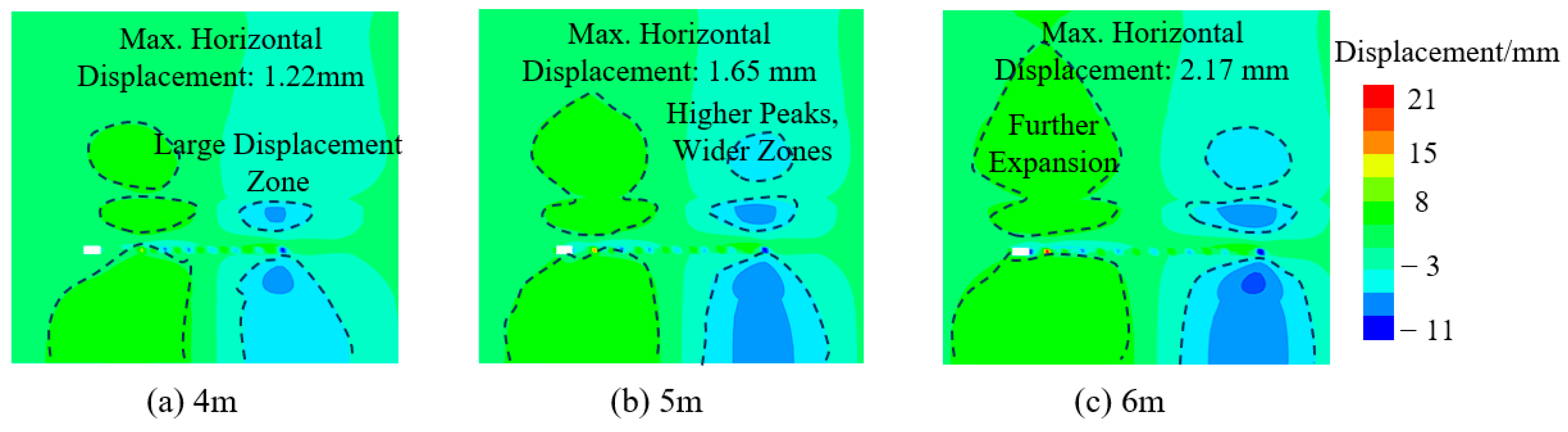
To investigate the effect of branch-roadway width on overburden movement at a backfilling ratio of 97%, a vertical cross-section through the middle of the branch roadways was extracted at y = 71 m in the model. The horizontal displacement distributions for different branch-roadway widths are shown in Figure 6. As the branch-roadway width increased from 4 to 5 and 6 m, the maximum horizontal displacement increased from 1.22 to 1.65 and 2.17 mm, respectively. The zone of pronounced horizontal displacement progressively extended from the boundaries of the mining–backfilling area into the roof, floor, and surrounding strata. This behavior is attributed to the larger volume extracted in each mining operation and the increased unsupported roof span associated with wider branch roadways, which intensified disturbance to the surrounding rock and consequently increased both the magnitude and spatial extent of horizontal displacement.
Figure 6.
Horizontal displacement for different branch-roadway widths at a backfilling ratio of 97%.
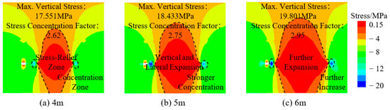
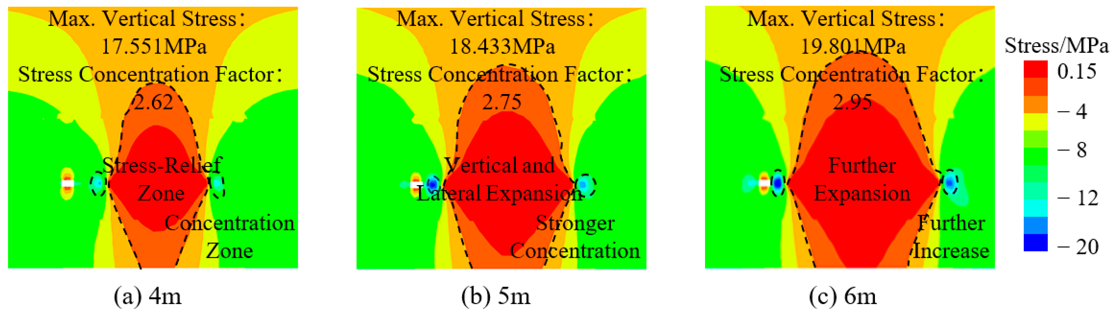
To investigate the effect of branch-roadway width on the vertical stress distribution in the coal and rock masses at a backfilling ratio of 97%, a vertical cross-section through the middle of the branch roadways was extracted at y = 71 m in the model. The stress distributions are shown in Figure 7. In all scenarios, pronounced unloading occurred within the mining–backfilling area, while the overburden load was transferred to its boundaries and the adjacent unmined coal, resulting in stress concentrations along the boundaries. As the branch-roadway width increased from 4 to 6 m, the high-stress zones progressively extended into the roof, floor, and strata on both sides, and the stress gradients near the branch roadways became more pronounced. The stress concentration factors for branch-roadway widths of 4, 5, and 6 m were 2.62, 2.75, and 2.96, respectively, indicating that stress concentration increased progressively with branch-roadway width. Wider branch roadways expanded the extent of load redistribution within and around the mining–backfilling area, causing further transfer of the overburden load to the backfill and adjacent unmined coal and thereby intensifying local stress concentrations.
Figure 7.
Vertical stress distributions for different branch-roadway widths at a backfilling ratio of 97%.
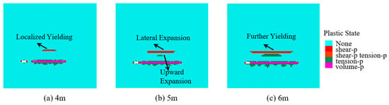
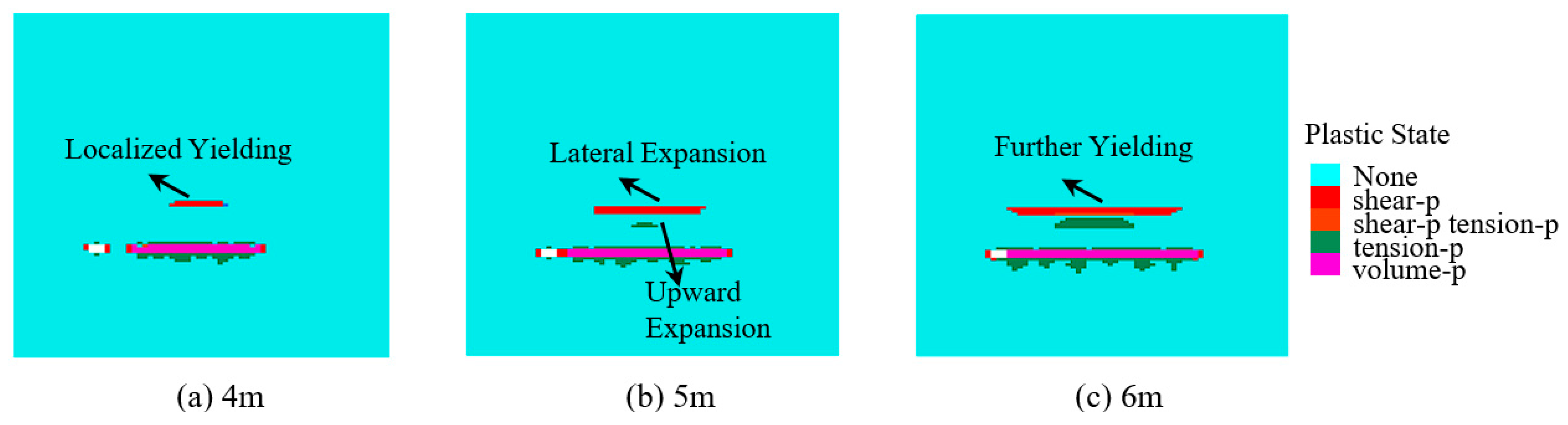
The plastic state distributions for different branch-roadway widths were obtained from a vertical cross-section through the middle of the branch roadways at y = 71 m, as shown in Figure 8. At a branch-roadway width of 4 m, the roof plastic zone and the extent of shear yielding were limited, indicating relatively good overall stability of the surrounding rock. When the width increased to 5 m, the roof shear-yield zones extended markedly along the mining–backfilling area and gradually formed continuous bands, indicating a transition from localized roof failure to laterally connected failure zones. As the width further increased to 6 m, the roof plastic zone expanded laterally and upward, with combined shear and tensile yielding occurring locally and a more pronounced plastic response developing in the floor. These results demonstrate that increasing the branch-roadway width from 4 to 6 m progressively changed the roof failure pattern from localized shear yielding to continuous shear-yield zones with localized combined shear and tensile yielding. This evolution indicates that wider branch roadways enlarged the unsupported roof area and the zone of stress redistribution along the mining–backfilling boundaries, promoting the lateral expansion and local coalescence of plastic failure zones in the surrounding rock.
Figure 8.
Plastic zone distributions for different branch-roadway widths at a backfilling ratio of 97%.
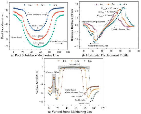
To further characterize the spatial variations in overburden response and load redistribution within the mining–backfilling area for different branch-roadway widths, monitoring lines for roof subsidence, horizontal displacement, and vertical stress were established through the central part of the mining–backfilling area at y = 159 m and elevations of z = 3 m and 5.5 m. Each monitoring line was 110 m long, and the extracted results are shown in Figure 9.
Figure 9.
Overburden displacement and vertical stress at 97% backfilling.
As shown in Figure 9a–c, increasing the branch-roadway width markedly intensified mining-induced disturbance, with concurrent increases in overburden displacement and the extent of stress redistribution. As the branch-roadway width increased from 4 to 6 m, the maximum roof subsidence along the monitoring line increased from 39.17 to 61.33 mm, an increase of 56.57%, while the inflection points on both sides of the subsidence trough shifted outward. The maximum absolute horizontal displacement increased from approximately 2.7 to 3.7 mm, an increase of approximately 37.0%, accompanied by an expansion of the affected area. Meanwhile, the stress-relief zone within the mining–backfilling area expanded further, and the peak abutment stress at its boundaries increased from approximately 12.5 to 15.5 MPa, an increase of approximately 24%, with the peak locations shifting outward toward the unmined coal on both sides. These results indicate that wider branch roadways significantly increased roof bending and subsidence, amplified horizontal displacement of the surrounding rock, and intensified stress redistribution and abutment stress concentrations along the mining–backfilling boundaries. This behavior primarily results from the larger volume extracted in each mining operation and the greater effective unsupported roof span, which increase roof bending deformation and extend the zone affected by mining. At the same time, greater stress relief within the mining–backfilling area transfers more of the overburden load to the adjacent unmined coal and backfill, raising the boundary abutment stress and shifting its peaks outward. Thus, the principal effects of increasing branch-roadway width are greater roof subsidence, larger horizontal displacement, and stronger abutment stress concentrations along the mining–backfilling boundaries.
3.2. Effect of Backfilling Ratio
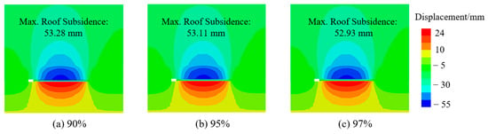
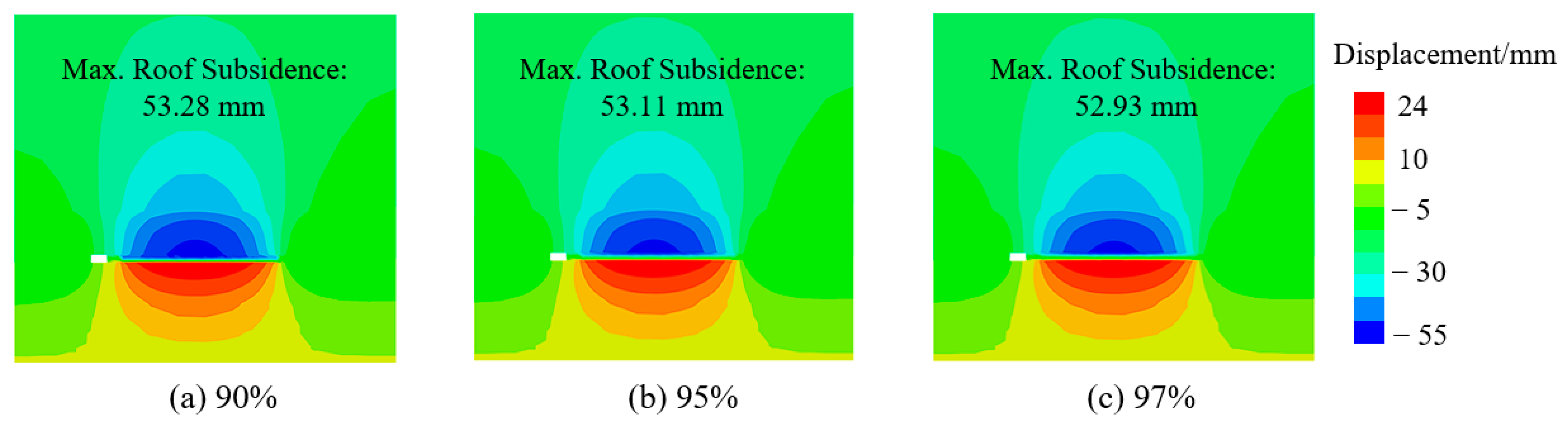
With the branch-roadway width fixed at 5 m, a vertical cross-section through the middle of the branch roadways was extracted at y = 71 m in the model to obtain the vertical displacement distributions of the overburden at backfilling ratios of 90%, 95%, and 97%, as shown in Figure 10. In all three scenarios, the subsidence center was located above the roof of the mining–backfilling area, with displacement progressively decreasing upward into the overburden and laterally toward both sides. The overall displacement patterns were largely consistent. As the backfilling ratio increased from 90% to 95% and 97%, the zone of pronounced displacement near the roof contracted slightly, and the maximum roof subsidence decreased from 53.28 to 53.11 and 52.93 mm, respectively. The reduction from 90% to 97% was only 0.65%, indicating that increasing the backfilling ratio within this high range further reduced roof deformation, but with limited improvement. This is because a higher backfilling ratio corresponds to a lower compressive deformation capacity of the backfill, thereby reducing backfill compression under overburden loading and providing greater restraint against roof movement. However, once the backfilling ratio reaches approximately 90%, the compressive deformation of the backfill is already limited. Further increases therefore produce progressively smaller reductions in backfill compression and roof subsidence, resulting in little change in the displacement field.
Figure 10.
Roof subsidence for different backfilling ratios at a branch-roadway width of 5 m.
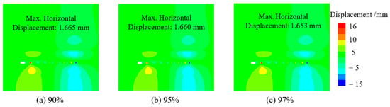
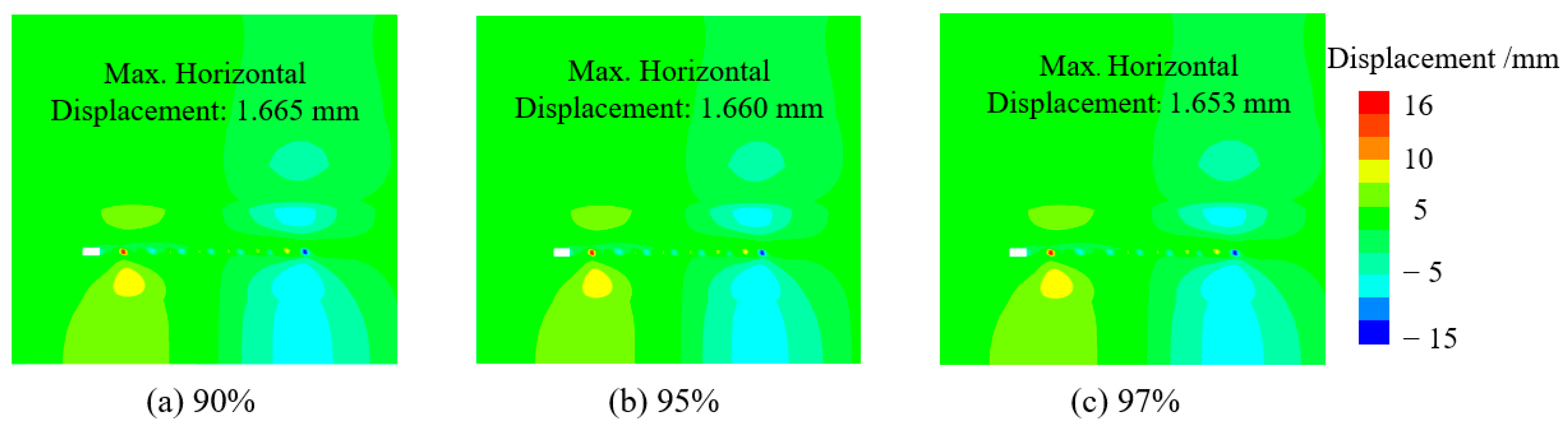
With the branch-roadway width fixed at 5 m, a vertical cross-section through the middle of the branch roadways was extracted at y = 71 m in the model to obtain the horizontal displacement distributions for different backfilling ratios, as shown in Figure 11. As the backfilling ratio increased from 90% to 95% and 97%, the overall pattern of the horizontal displacement field and the extent of the zones of pronounced displacement remained largely unchanged. The maximum horizontal displacements were 1.665, 1.660, and 1.653 mm, respectively, representing a reduction of only 0.012 mm over the 90–97% range. These results indicate that further increases in the backfilling ratio within this high range have a limited effect on restraining horizontal movement of the surrounding rock. This is because the mined-out space is already adequately supported when the backfilling ratio reaches approximately 90%. Although further increases in the backfilling ratio reduce the compressive deformation of the backfill, the branch-roadway span and the spatial configuration of the mining–backfilling area remain unchanged. Consequently, the reductions in both the magnitude and spatial extent of horizontal displacement are limited.
Figure 11.
Horizontal displacement for different backfilling ratios at a branch-roadway width of 5 m.
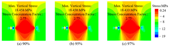
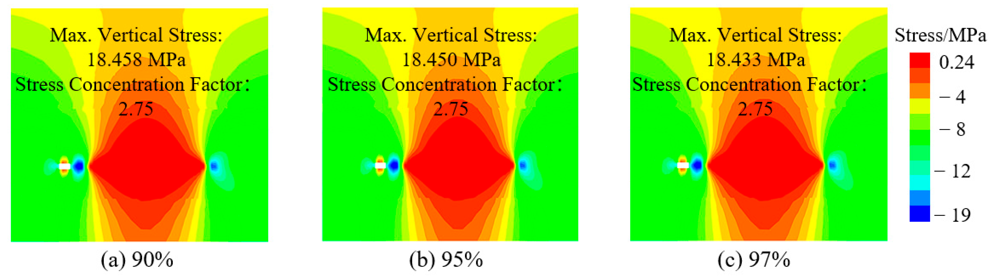
In the model with a branch-roadway width of 5 m, a vertical cross-section through the middle of the branch roadways was extracted at y = 71 m. The vertical stress distributions in the coal and rock masses for different backfilling ratios are shown in Figure 12. All scenarios exhibited stress relief in the central part of the mining–backfilling area and localized stress concentrations on both sides of the branch roadways. As the backfilling ratio increased from 90% to 95% and 97%, the maximum vertical stress decreased from 18.458 to 18.450 and 18.433 MPa, respectively, representing a total reduction of only 0.14%, while the stress concentration factor remained approximately 2.75. The outlines of the high-stress zones and the locations of the stress-relief zones on both sides remained largely unchanged. These results indicate that increasing the backfilling ratio within the high range of 90–97% has little effect on stress concentration and load transfer within the mining–backfilling area. This is primarily because increasing the backfilling ratio reduces the compressive deformation of the backfill, while the branch-roadway span, the dimensions of the unmined coal, and the overall spatial configuration of the mining–backfilling area remain unchanged. Consequently, the principal load-transfer pattern is not appreciably altered.
Figure 12.
Vertical stress distributions for different backfilling ratios at a branch-roadway width of 5 m.
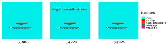
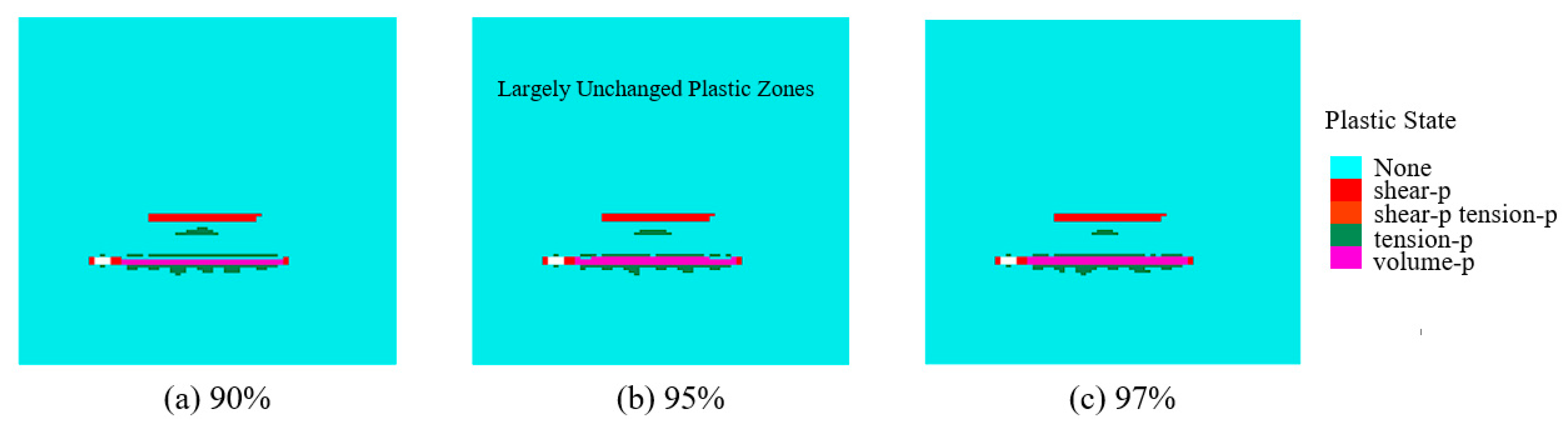
A vertical cross-section through the middle of the branch roadways was extracted at y = 71 m in the model. The plastic zone distributions in the coal and rock masses for different backfilling ratios are shown in Figure 13. In all scenarios, the plastic response was concentrated primarily in the roof and floor of the mining–backfilling area and along the branch-roadway margins. Shear yielding in the roof formed bands along bedding planes, whereas volumetric yielding associated with compaction under loading predominated within the backfill. As the backfilling ratio increased from 90% to 97%, the principal locations of plastic zone development and the failure modes remained largely unchanged, with only a slight contraction of the roof plastic zone. These results indicate that the mined-out space was already adequately supported within the high backfilling ratio range of 90–97%, and further increases had a limited effect on reducing the extent of plastic yielding in the surrounding rock.
Figure 13.
Plastic zone distributions for different backfilling ratios at a branch-roadway width of 5 m.
To further investigate the effects of backfilling ratio on overburden deformation, stress, and plastic failure, additional scenarios with backfilling ratios of 83%, 85%, 87%, and 89% were simulated using the model with a branch-roadway width of 5 m and compared with the 90%, 95%, and 97% scenarios.
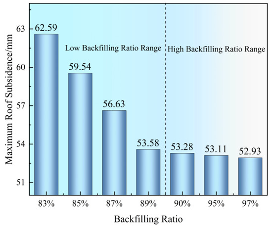
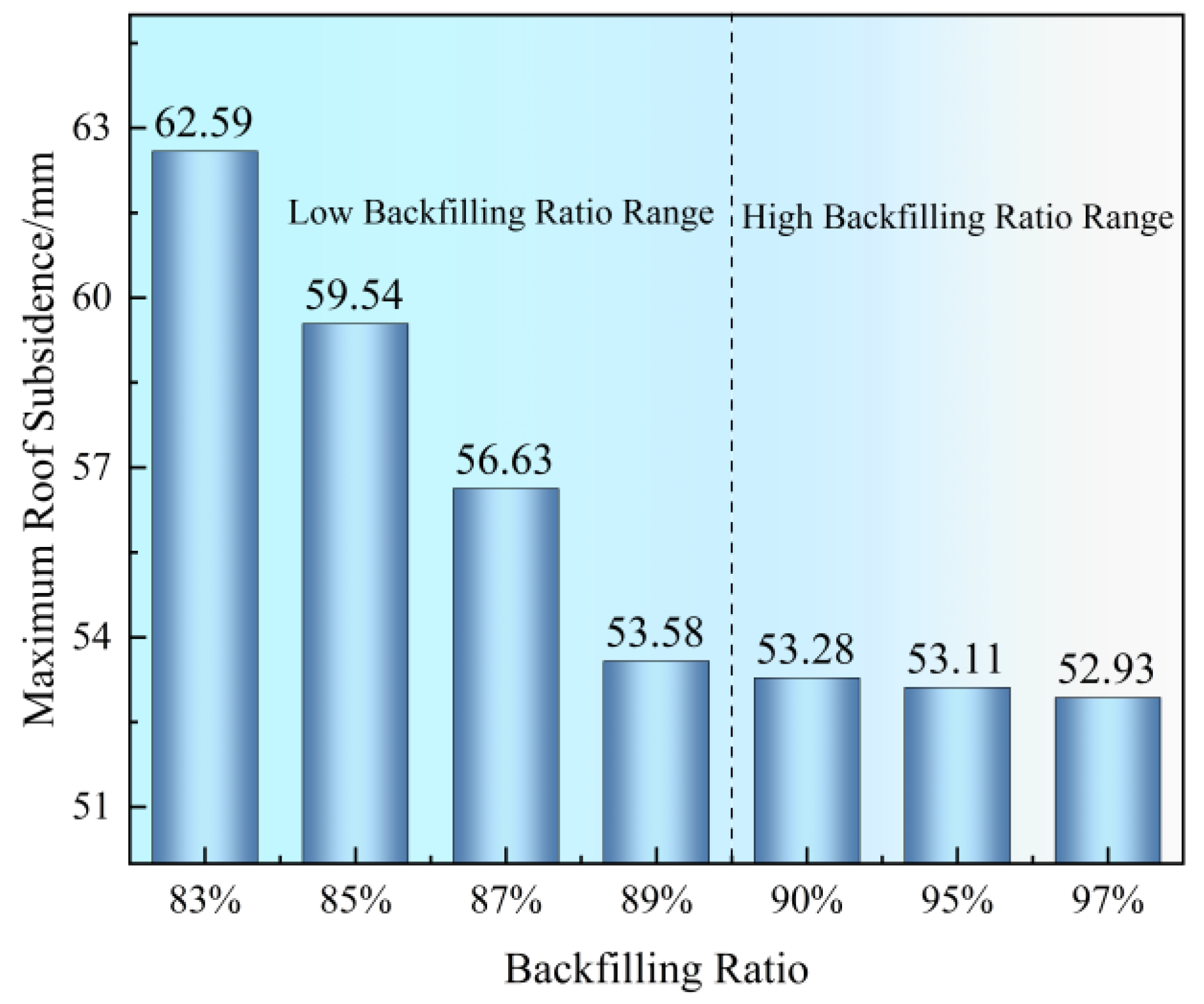
Figure 14 shows the variation in maximum roof subsidence with backfilling ratio. As the backfilling ratio increased from 83% to 89%, the maximum roof subsidence decreased from 62.59 to 53.58 mm, a total reduction of 9.01 mm, or 14.4%. In contrast, increasing the backfilling ratio from 90% to 97% reduced the maximum roof subsidence from 53.28 to 52.93 mm, a decrease of only 0.35 mm. These results indicate a pronounced diminishing-return response of roof subsidence to increasing backfilling ratio, with a marked reduction in sensitivity around 89–90%. Within the 83–89% range, increasing the backfilling ratio substantially reduced the compressive deformation capacity of the backfill. Consequently, backfill compression under overburden loading was reduced and the restraint against roof movement was enhanced, resulting in a pronounced reduction in roof subsidence. Once the backfilling ratio reached approximately 90%, the compressive deformation of the backfill was already limited, and further increases therefore produced progressively smaller reductions in roof subsidence.
Figure 14.
Effect of backfilling ratio on roof subsidence at a branch-roadway width of 5 m.
The maximum vertical stresses at backfilling ratios of 83%, 85%, 87%, and 89% were 18.463, 18.465, 18.459, and 18.458 MPa, respectively. Together with the results for backfilling ratios of 90%, 95%, and 97%, these values indicate that increasing the backfilling ratio from 83% to 97% reduced the maximum vertical stress by only 0.030 MPa, or approximately 0.16%. The plastic failure characteristics of the coal and rock masses remained largely unchanged across the different backfilling ratios, with only slight localized contraction of the roof plastic zone. These results indicate that, at a branch-roadway width of 5 m and within the backfilling ratio range of 83–97%, increasing the backfilling ratio primarily reduces the compressive deformation of the backfill and thereby limits roof deformation, while having little effect on the peak stress in the mining area or the extent of plastic failure in the coal and rock masses.
3.3. Coupled Effects of Branch-Roadway Width and Backfilling Ratio
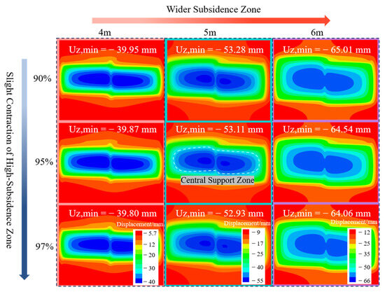
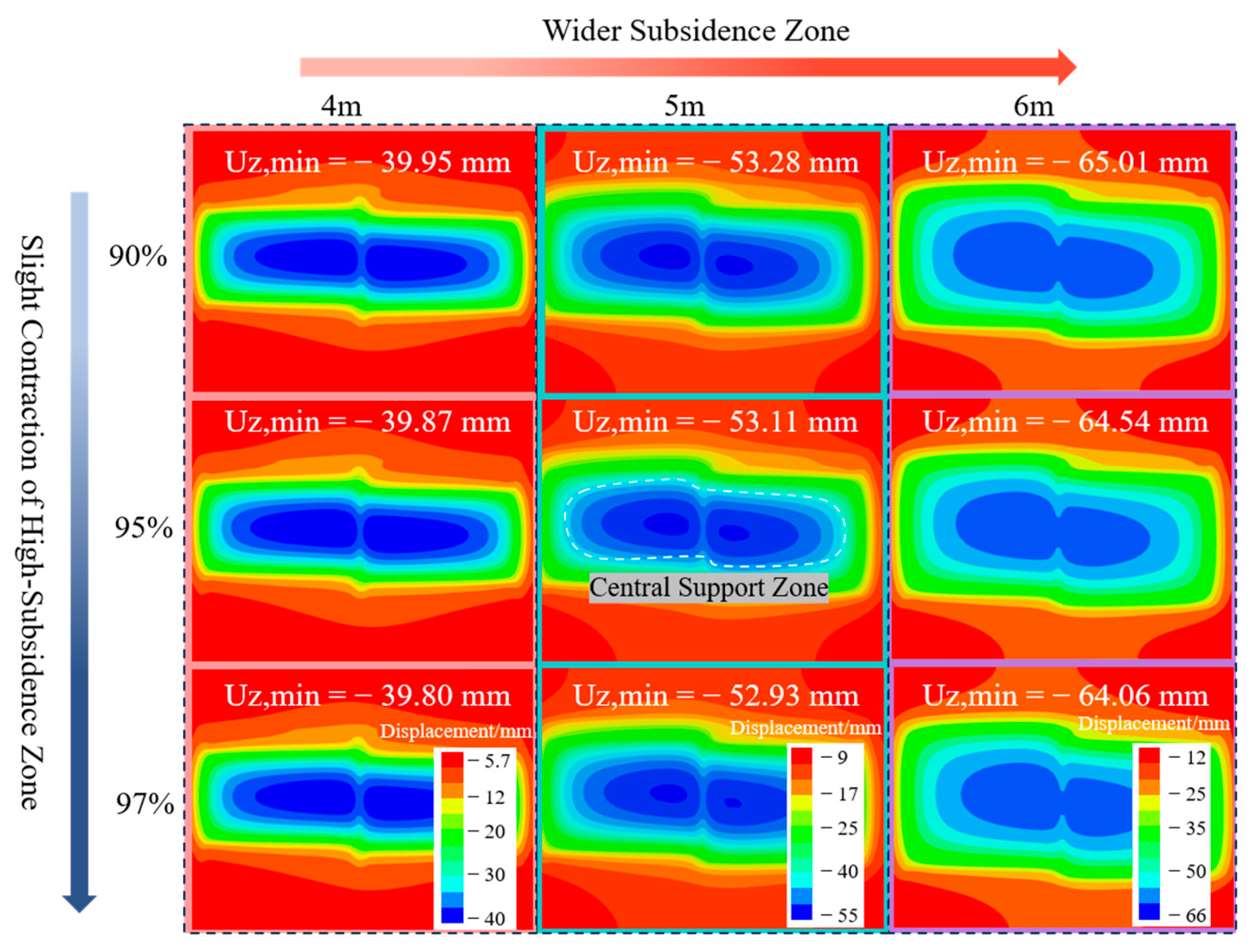
To analyze the matching relationship between backfilling ratio and branch-roadway width, a horizontal slice was extracted at z = 3.5 m in the model to obtain the roof vertical displacement distributions for different parameter combinations, as shown in Figure 15. In all nine scenarios, distinct subsidence centers formed on both sides of the central main haulage roadway. Roof subsidence gradually decreased outward from the mining–backfilling areas in the two wings, while zones of relatively low subsidence formed above the central roadway and the retained coal. As the branch-roadway width increased, the zones of pronounced subsidence progressively expanded along the mining–backfilling areas, substantially extending the influence of subsidence in both wings and enlarging the overall roof subsidence zone. At a constant branch-roadway width, increasing the backfilling ratio from 90% to 97% produced little change in the locations of the subsidence centers or the spatial pattern of roof displacement, with only a slight contraction of the zones of pronounced subsidence. These results indicate that, within the investigated parameter ranges, branch-roadway width has a more pronounced effect on the extent and spatial distribution of roof subsidence. Further increases in backfilling ratio within the high range primarily reduce local subsidence magnitudes, with limited effects on the overall roof displacement pattern.
Figure 15.
Roof subsidence under different roadway widths and backfilling ratios.
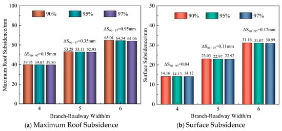
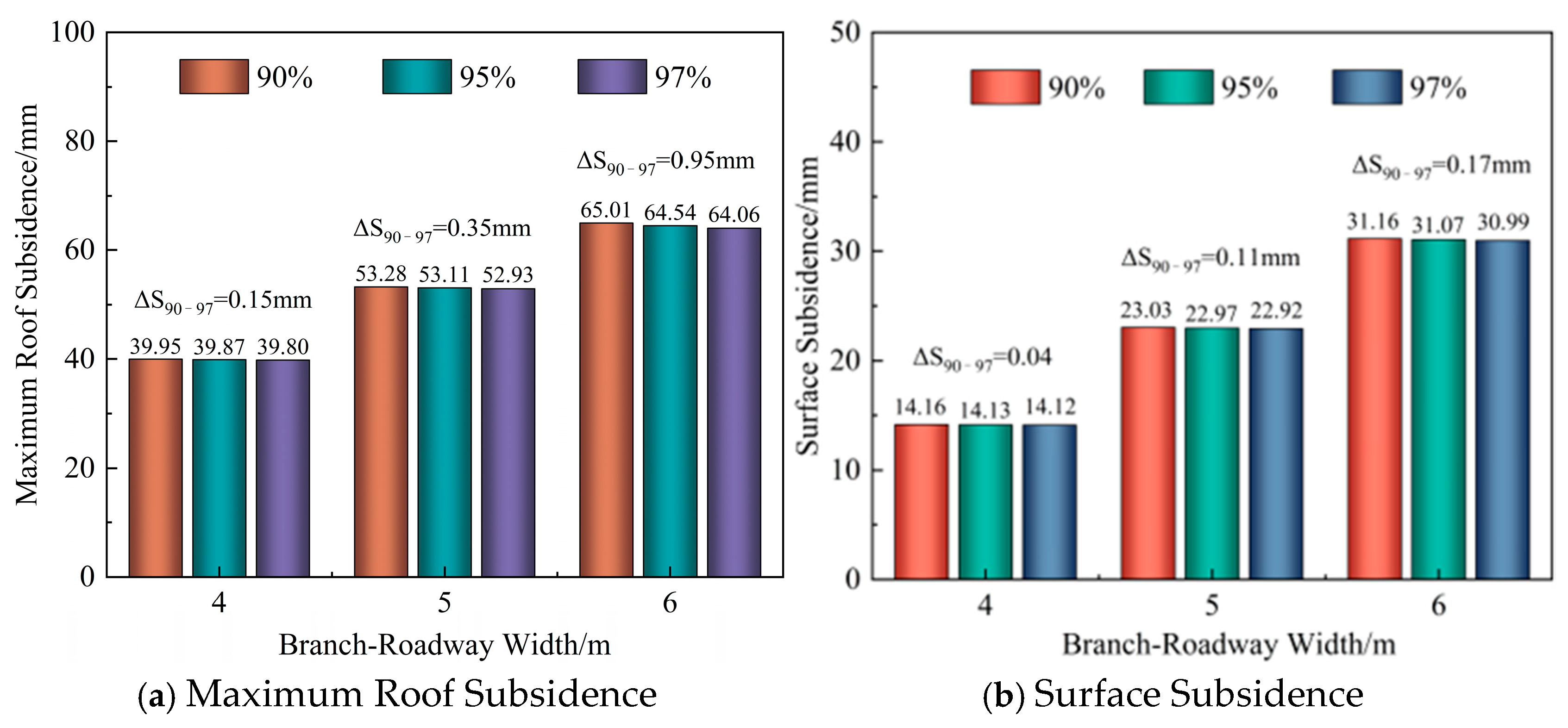
To further quantify the effects of branch-roadway width and backfilling ratio on roof and surface deformation, the maximum roof subsidence was extracted from the horizontal slice at z = 3.5 m for each of the nine simulation scenarios. At the model surface, a monitoring line with 29 points was arranged along the strike direction through the middle of the working face, and a second line with 47 points was arranged along the dip direction across both wings. The two lines comprised a total of 76 surface displacement monitoring points, from which the maximum surface subsidence was determined for each scenario. The results are shown in Figure 16.
Figure 16.
Maximum roof and surface subsidence.
Figure 16a shows the maximum roof subsidence for different combinations of branch-roadway width and backfilling ratio. At a constant backfilling ratio, the maximum roof subsidence increased markedly with branch-roadway width. Increasing the width from 4 to 6 m increased the maximum roof subsidence by 25.066, 24.670, and 24.252 mm at backfilling ratios of 90%, 95%, and 97%, respectively, with all relative increases exceeding 60%. At a constant branch-roadway width, increasing the backfilling ratio from 90% to 97% reduced the maximum roof subsidence by 0.145, 0.347, and 0.959 mm for widths of 4, 5, and 6 m, respectively. The reduction in subsidence therefore increased with branch-roadway width. These results indicate that increasing the backfilling ratio is relatively more effective in controlling roof subsidence in wider branch roadways; however, this reduction remains much smaller than the increase in roof subsidence caused by widening the branch roadways.
Figure 16b shows the maximum surface subsidence for different combinations of branch-roadway width and backfilling ratio. At a constant backfilling ratio, increasing the branch-roadway width from 4 to 6 m increased the maximum surface subsidence by approximately 16.9 mm. At a backfilling ratio of 90%, it increased from 14.163 to 31.155 mm, representing an increase of 120.0%. This indicates that increasing branch-roadway width substantially expands the extent of overburden movement and increases the magnitude of surface subsidence. At a constant branch-roadway width, increasing the backfilling ratio from 90% to 97% reduced the maximum surface subsidence by only 0.042–0.168 mm, indicating little overall change. These results demonstrate that maximum surface subsidence follows the same trend as maximum roof subsidence and that, within the high backfilling ratio range of 90–97%, surface subsidence is considerably more sensitive to changes in branch-roadway width than to changes in backfilling ratio.
Overall, the above results indicate that branch-roadway width has a substantially greater influence on roof deformation, stress concentration, and surface subsidence than variations in backfilling ratio within the high-backfilling-ratio range. To further demonstrate the engineering rationale for parameter selection, the candidate branch-roadway widths and backfilling ratios were comprehensively compared by considering the numerical simulation results together with roof stability, mining–backfilling efficiency, and field engineering control requirements, as summarized in Table 5.
Table 5.
Comparison of branch-roadway width and backfilling ratio schemes.
As shown in Table 5, although a branch-roadway width of 4 m provides better control of roof deformation and stress concentration, reducing the roadway width increases the number of branch roadways and mining–backfilling cycles required to achieve the same extraction target. Under the same total extraction area and branch-roadway length, the 4 m scheme would theoretically require approximately 25% more branch-roadway development footage and mining–backfilling cycles than the 5 m scheme. At the Taitou Coal Mine, an EBZ-160D roadheader (Shenyang North Traffic Heavy Industry Ltd., Shenyang, China) is used for coal-roadway development, with an average advance rate of approximately 7 m/d, and the mining cycle of an 80 m branch roadway under the three-roadway roadheader scheme is approximately 11.4 d. In contrast, a width of 6 m increases the extraction capacity of an individual branch roadway but results in markedly greater roof subsidence, stress concentration, and surface subsidence. Considering the calculated limiting roof span of 6.19 m and a safety factor of 1.2, a branch-roadway width of 5 m provides a more reasonable balance among roof stability, deformation control, and construction efficiency.
For the backfilling ratio, the numerical results show that further increases within the range of 90–97% provide only limited additional improvement in deformation control. The field engineering design for building protection requires a backfilling control level of no less than 95%; therefore, the 90% case was used only for parameter sensitivity analysis and was not considered as a field design value. When the backfilling ratio was further increased from 95% to 97%, the maximum roof subsidence and maximum surface subsidence decreased by only 0.179 mm and 0.053 mm, respectively, while no appreciable changes were observed in stress concentration or plastic zone distribution. This indicates that the additional benefit of further increasing the backfilling ratio is limited. Therefore, considering both the numerical simulation results and the engineering control requirements, a branch-roadway width of 5 m and a backfilling ratio of 95% were selected as the parameters for field application.
3.4. Field Test and Engineering Application
The preceding analyses indicate that branch-roadway width substantially affects roof subsidence, stress concentration, plastic zone expansion, and surface subsidence by altering the unsupported roof span and the spatial configuration of the mining–backfilling area. The backfilling ratio primarily regulates roof subsidence by controlling the compressive deformation of the backfill, with relatively limited effects on peak stress and plastic zone distributions in the coal and rock masses within the high backfilling-ratio range. Considering the space required for equipment operation, branch-roadway development conditions, and numerical simulation results, a branch-roadway width of 5 m and a backfilling ratio of 95% were adopted for the full-scale field trial. Branch-roadway extraction and backfilling by grout injection into bags were carried out using this parameter combination to evaluate its effectiveness in controlling surface subsidence. It should be noted that the numerical surface-subsidence results represent the final response after completion of all four mining–backfilling rounds.
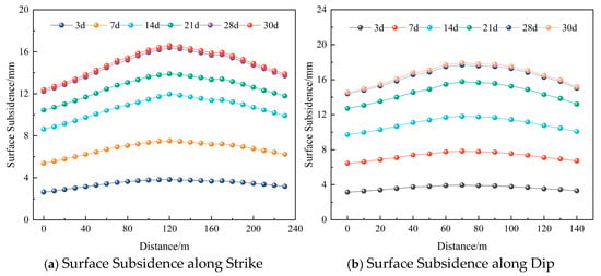
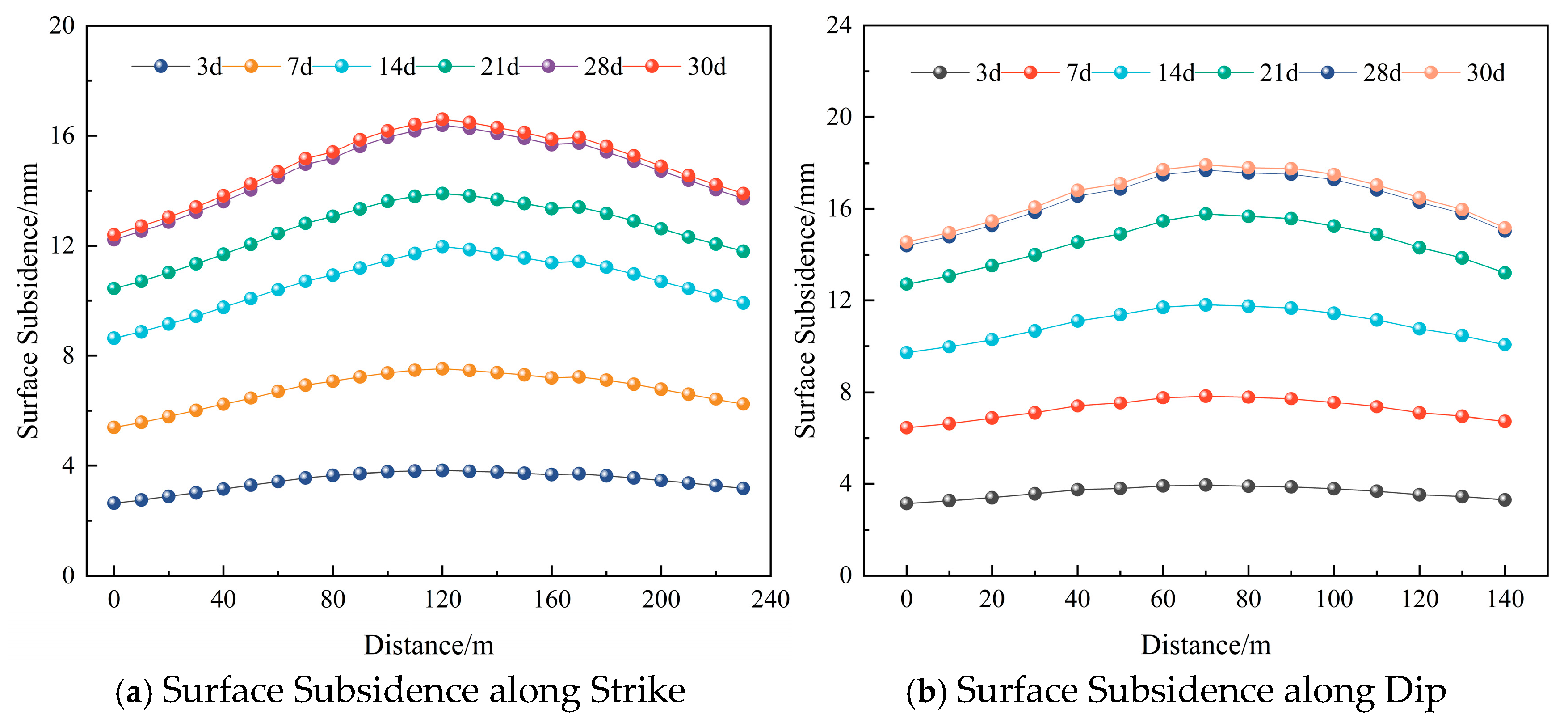
Surface subsidence monitoring lines were established along the strike and dip directions above the 11205 trial backfill mining face, with their projected layout shown in Figure 2. Surface subsidence was monitored using precision digital level together with an Invar barcode staff. The instrument has a standard deviation of 0.3 mm per kilometer for double-run leveling. Stable benchmarks were established outside the mining-influence zone and used as fixed elevation references for all monitoring campaigns. Closed leveling routes were adopted for repeated measurements and error checking. The strike monitoring line was 230 m long and comprised 24 monitoring points, while the dip monitoring line was 140 m long and comprised 15 monitoring points. The point spacing along both lines was 10 m, and Following completion of all mining–backfilling operations, measurements were conducted on days 3, 7, 14, 21, 28, and 30 during the subsequent 30-day monitoring period. The monitoring results are shown in Figure 17.
Figure 17.
Surface subsidence monitoring results for the 11205 trial backfill mining face.
As shown in Figure 17, both the strike and dip subsidence profiles exhibit broad, gently sloping troughs, with greater subsidence in the central region and smaller subsidence toward both sides. The maximum subsidence zones are located near the 120 m position along the strike monitoring line and the 70 m position along the dip monitoring line, respectively. Subsidence along both lines increased over time, but at a progressively lower rate, while the profile shapes and the extent of the maximum subsidence zones remained largely unchanged. The maximum subsidence recorded during the monitoring period occurred on day 30, reaching only 16.60 mm along strike and 17.93 mm along dip. Between days 28 and 30, these maxima increased by only 0.22 and 0.25 mm, respectively, indicating that the subsidence increment became relatively small toward the end of the monitoring period. Under the selected 5 m branch-roadway width and 95% backfilling-ratio condition, the numerical model predicted a maximum surface subsidence of 22.97 mm, whereas the maximum measured values at 30 days were 16.60 mm along strike and 17.93 mm along dip. The lower measured values may be partly attributed to the different temporal states represented by the two results, because the numerical result corresponds to the final response after completion of all four mining–backfilling rounds, whereas the field measurements represent the surface response recorded during the subsequent 30-day post-mining monitoring period. The monitoring results indicate that surface subsidence remained relatively limited under the 5 m branch-roadway width and 95% backfilling-ratio condition during the 30-day monitoring period, with a marked reduction in the subsidence increment between days 28 and 30. However, the 30-day monitoring period is insufficient to fully characterize long-term residual subsidence after mining. Therefore, the present results mainly reflect the short-term subsidence-control performance of the selected parameter combination. Longer-term field monitoring, together with evaluation of building-protection indicators such as tilt, curvature, and horizontal deformation, is required to assess long-term subsidence and its potential effects on surface structures.
4. Discussion
The above results indicate that the overburden response under three-roadway continuous mining and backfilling exhibits distinct stages of evolution. The operational arrangement featuring paired branch roadways, extraction at intervals, and backfilling behind the advancing mining operations creates an alternating distribution of unmined coal, backfilled roadways, and voids created at successive extraction stages. Consequently, support conditions in the mining area evolve as mining and backfilling progress. Overburden movement is therefore governed not only by backfill compression but also by the scale of branch-roadway extraction, the load carried by unmined coal at each stage, and the progressive mobilization of backfill support.
- (1)
- Compared with mining methods in which backfill collectively supports the roof after a continuous mined-out space has formed, three-roadway continuous mining and backfilling limits the unsupported roof area created during each extraction stage through successive rounds of extraction and timely backfilling. Overburden movement thus develops progressively under the combined effects of localized extraction, support at successive stages, and load transfer. As the mining–backfilling rounds advance, the load-bearing role gradually shifts from unmined coal to hardened backfill, limiting large-scale simultaneous movement of the overburden. This alternating load-bearing mechanism associated with extraction, coal retention, and backfilling is a key feature of the overburden control process.
- (2)
- Branch-roadway width and backfilling ratio influence the overburden response through different mechanisms. Branch-roadway width directly alters the space created during each extraction stage, the unsupported roof span, and the extent of load redistribution along the mining–backfilling boundaries, thereby substantially affecting roof deformation, stress redistribution, and plastic response. By contrast, the backfilling ratio acts primarily by regulating the compressive deformation capacity of the backfill. A higher backfilling ratio corresponds to lower backfill compression under overburden loading, thereby providing greater restraint against roof movement and reducing roof subsidence. Further increases within the high backfilling-ratio range produce little change in horizontal displacement, the stress field, or the overall plastic zone distribution. Thus, branch-roadway width primarily governs the spatial characteristics of the overburden response, whereas the backfilling ratio mainly regulates deformation magnitude through the compaction behavior of the backfill.
- (3)
- Several limitations of this study should be acknowledged. First, the numerical model represents the mechanical responses of the coal–rock mass and backfill using simplified constitutive relationships and fixed mechanical parameters, which cannot fully reproduce the complexity of in situ strata and backfill materials. Second, the time-dependent development of backfill strength and deformation properties was not explicitly simulated; instead, hardened backfill parameters were used to represent its load-bearing state. In addition, the field monitoring period was limited to 30 days. Although the subsidence rate decreased markedly toward the end of the monitoring period, the available measurements are insufficient to determine whether long-term residual subsidence had fully stabilized, and the long-term deformation response of surface buildings was not continuously monitored. Therefore, the present findings are primarily applicable to the geological and engineering conditions of the 11205 working face, and their applicability to other mines or different geological conditions requires further verification.
5. Conclusions
Taking the 11205 working face beneath buildings at the Taitou Coal Mine as a case study, this study developed a fully mechanized compact backfill mining scheme based on three-roadway continuous mining and backfilling. The effects of branch-roadway width and backfilling ratio on roof subsidence, horizontal displacement, vertical stress, plastic zones, and surface subsidence were analyzed, and the subsidence-control performance of the selected parameter combination was verified through field monitoring. The main conclusions are as follows:
- (1)
- The operational arrangement featuring paired branch roadways, extraction at intervals, and backfilling behind the advancing mining operations creates an alternating distribution of unmined coal, backfilled roadways, and voids formed at successive extraction stages. During mining and backfilling, the primary roof-supporting role gradually shifts from unmined coal to hardened backfill, establishing an alternating load-bearing mechanism associated with extraction, coal retention, and backfilling. This arrangement limits the continuous unsupported roof area created during each extraction stage and reduces large-scale simultaneous overburden movement, providing a basis for overburden movement and surface subsidence control under three-roadway continuous mining and backfilling.
- (2)
- Branch-roadway width is an important parameter governing overburden movement and stress redistribution in the mining area. At a backfilling ratio of 97%, the maximum roof subsidence values for branch-roadway widths of 4, 5, and 6 m were 40.41, 52.93, and 65.21 mm, respectively, representing increases of 30.9% and 61.4% for the 5 and 6 m scenarios relative to the 4 m scenario. The corresponding maximum absolute horizontal displacements were 1.220, 1.653, and 2.174 mm, with the affected area expanding as branch-roadway width increased. The stress concentration factors were 2.62, 2.75, and 2.96, respectively, indicating markedly stronger abutment stress concentrations along the mining–backfilling boundaries. Wider branch roadways increased the space created during each extraction stage and the effective unsupported roof span, simultaneously intensifying roof subsidence, horizontal displacement of the surrounding rock, and boundary stress redistribution, while extending the zone of mining-induced overburden disturbance.
- (3)
- The backfilling ratio had a comparatively limited effect on the overall overburden response but regulated roof subsidence to some extent. At a branch-roadway width of 5 m, increasing the backfilling ratio from 83% to 89% reduced the maximum roof subsidence from 62.59 to 53.58 mm, a decrease of 9.01 mm, or 14.4%. These results indicate a pronounced diminishing-return response, with the sensitivity of roof subsidence to increasing backfilling ratio decreasing markedly around 89–90%. Meanwhile, the maximum horizontal displacement decreased only from 1.665 to 1.653 mm over the 90–97% range. Increasing the backfilling ratio from 83% to 97% reduced the maximum vertical stress by only 0.030 MPa, while the overall plastic zone distribution in the coal and rock masses changed little. These results indicate that increasing the backfilling ratio primarily limits roof subsidence by reducing the compressive deformation of the backfill under loading. Further increases at high backfilling ratios provide limited improvements in horizontal displacement, peak stress, and plastic zone distribution.
- (4)
- Considering overburden control, surface subsidence response, and field construction conditions, a branch-roadway width of 5 m and a backfilling ratio of 95% were selected for field application at the 11205 working face. At a branch-roadway width of 5 m, increasing the backfilling ratio from 95% to 97% reduced the maximum roof subsidence and maximum surface subsidence by only 0.179 and 0.053 mm, respectively, indicating limited additional subsidence-control benefits. Under the selected combination of a 5 m branch-roadway width and a 95% backfilling ratio, the numerical model predicted a maximum surface subsidence of 22.97 mm, while the maximum monitored subsidence values at 30 days were 16.60 mm along strike and 17.93 mm along dip. Between days 28 and 30, the monitored maxima increased by only 0.22 and 0.25 mm, respectively. The numerical and field results were of the same order of magnitude, indicating satisfactory short-term surface-subsidence control during the 30-day monitoring period. However, longer-term monitoring is still required to evaluate residual subsidence and the long-term deformation response of surface buildings.
Author Contributions
Conceptualization, J.X. and S.Z.; methodology, J.X. and S.Z.; software, J.X.; validation, J.X., S.Z. and G.F.; formal analysis, J.X.; investigation, J.X., T.A., S.L. and Z.W.; resources, S.Z. and G.F.; data curation, J.X., Z.K., S.L. and Z.W.; writing—original draft preparation, J.X.; writing—review and editing, J.X., X.L. and S.Z.; visualization, J.X. and Z.K.; supervision, S.Z.; project administration, S.Z.; funding acquisition, S.Z. All authors have read and agreed to the published version of the manuscript.
Funding
This research was funded by the Guizhou Provincial Major Science and Technology Project, grant number Qian Ke He Platform NSSYS [2025] Major Project 001, and the National Natural Science Foundation of China, grant number 52574177.
Institutional Review Board Statement
Not applicable.
Informed Consent Statement
Not applicable.
Data Availability Statement
The data supporting the findings of this study are available from the corresponding author upon reasonable request.
Conflicts of Interest
Author Xiangling Li was employed by the company No. 3 Bureau of China Metallurgical Geology Bureau. The remaining authors declare that the research was conducted in the absence of any commercial or financial relationships that could be construed as a potential conflict of interest.
References
- Wu, T.; Fang, X.; Ning, S.; Wu, Z.; Xu, F. Study on status quo and development as well as utilization of coal resources “under buildings, water bodies, railways and above confined water” in North China Coalfields. Coal Sci. Technol. 2021, 49, 129–135. [Google Scholar] [CrossRef]
- Zhang, J.; Zhang, Q.; Sun, Q.; Gao, R.; Germain, D.; Abro, S. Surface subsidence control theory and application to backfill coal mining technology. Environ. Earth Sci. 2015, 74, 1439–1448. [Google Scholar] [CrossRef] [Scilit]
- Chang, Q.; Chen, J.; Zhou, H.; Bai, J. Implementation of paste backfill mining technology in Chinese coal mines. Sci. World J. 2014, 2014, 821025. [Google Scholar] [CrossRef] [Scilit] [PubMed]
- Li, H.; Guo, G. Surface subsidence control mechanism and effect evaluation of gangue-backfilling mining: A case study in China. Geofluids 2018, 2018, 2785739. [Google Scholar] [CrossRef] [Scilit]
- Li, M.; Zhang, J.; Li, A.; Zhou, N. Reutilisation of coal gangue and fly ash as underground backfill materials for surface subsidence control. J. Clean. Prod. 2020, 254, 120113. [Google Scholar] [CrossRef] [Scilit]
- Li, M.; Zhang, J.; Jiang, H.; Huang, Y.; Zhang, Q. A thin plate on elastic foundation model of overlying strata for dense solid backfill mining. J. China Coal Soc. 2014, 39, 2369–2373. [Google Scholar] [CrossRef]
- Guo, G.; Zhu, X.; Zha, J.; Wang, Q. Subsidence prediction method based on equivalent mining height theory for solid backfilling mining. Trans. Nonferrous Met. Soc. China 2014, 24, 3302–3308. [Google Scholar] [CrossRef] [Scilit]
- Zhu, X.; Zha, F.; Guo, G.; Chang, Q.; Liu, H.; Yang, X. Mechanical prediction method of strata movement and surface subsidence in backfill-strip mining. Sci. Rep. 2024, 14, 31331. [Google Scholar] [CrossRef] [Scilit] [PubMed]
- Xu, B.; Yang, R.; Li, Y.; Lu, B.; Luo, H.; Li, C. Three measurement relationship and control principle of overburden movement in cemented filling. J. China Coal Soc. 2022, 47, 49–60. [Google Scholar]
- Zhang, Q.; Zhang, J.; Guo, S.; Gao, R.; Li, W. Design and application of solid, dense backfill advanced mining technology with two pre-driving entries. Int. J. Min. Sci. Technol. 2015, 25, 127–132. [Google Scholar] [CrossRef] [Scilit]
- Liu, P.; Wang, X. Method and verification of strength determination for dense filling coal mining filling body in comprehensive mechanized unit. Coal Sci. Technol. 2025, 53, 373–382. [Google Scholar] [CrossRef]
- Lyu, H.; Chen, Y.; Pu, H.; Jv, F.; Wu, P.; Shimada, H.; Sasaoka, T.; Hamanaka, A. Damage evolution laws and constitutive model description of loess-slag-based cemented backfill material. Constr. Build. Mater. 2025, 495, 143547. [Google Scholar] [CrossRef] [Scilit]
- Feng, X.; Zhang, N. Position-optimization on retained entry and backfilling wall in gob-side entry retaining techniques. Int. J. Coal Sci. Technol. 2015, 2, 186–195. [Google Scholar] [CrossRef] [Scilit]
- Jiao, S.; Liu, J.; Shang, L. Backfill automation system of comprehensive mechanized solid backfill coal mining. Coal Sci. Technol. 2015, 43, 109–113. [Google Scholar] [CrossRef]
- Sun, K.; Zhang, J.; He, M.; Li, M.; Guo, S. Control of surface deformation and overburden movement in coal mine area by an innovative roadway cemented paste backfilling method using mining waste. Sci. Total Environ. 2023, 891, 164693. [Google Scholar] [CrossRef] [Scilit] [PubMed]
- Bian, Z.; Miao, X.; Lei, S.; Chen, S.; Wang, W.; Struthers, S. The challenges of reusing mining and mineral-processing wastes. Science 2012, 337, 702–703. [Google Scholar] [CrossRef] [Scilit] [PubMed]
- Bo, L.; Yang, S.; Liu, Y.; Zhang, Z.; Wang, Y.; Wang, Y. Coal mine solid waste backfill process in China: Current status and challenges. Sustainability 2023, 15, 13489. [Google Scholar] [CrossRef] [Scilit]
- Liu, L.; Luo, Y.; Zhu, M.; Su, C.; Wu, T.; Wang, J.; Hang, Y. Mining technology and practice of full-solid waste cemented backfilling in narrow strip of extra-thick coal seam under buildings. Coal Sci. Technol. 2024, 52, 83–92. [Google Scholar]
- Ma, L.; Zhang, D.; Wang, S.; Xie, Y.; Yu, Y. Water-preserved mining with the method named “backfilling while mining”. J. China Coal Soc. 2018, 43, 62–69. [Google Scholar] [CrossRef]
- Ma, L.; Wang, S.; Yu, Y.; Dou, H. Technology and practice of continuous mining and backfilling with wall system for water conservation. J. Min. Saf. Eng. 2021, 38, 902–910+987. [Google Scholar]
- Chen, D.; Wang, X.; Bai, J.; Zhang, F. Deformation mechanism and control technology of gob-side roadway with continuous mining and continuous backfilling: A case study. Geomat. Nat. Hazards Risk 2024, 15, 2350480, Correction in Geomat. Nat. Hazards Risk 2024, 15, 2383075. [Google Scholar] [CrossRef] [Scilit]
- Lin, H.; Yang, Y.; Chen, C.; Ding, C. Influence of mining sequence of branch on stope pressure behaviour on continuous mining and continuous backfilling. Processes 2024, 12, 442. [Google Scholar] [CrossRef] [Scilit]
- Lin, H.; Yang, R.; Li, Y.; Fang, S. Stability of coal pillar and roof movement characteristics in roadway backfill mining. Adv. Civ. Eng. 2021, 2021, 5588923. [Google Scholar] [CrossRef] [Scilit]
- Meng, Z.; Dong, Y.; Zhang, X.; Jiao, F.; Fan, Y.; Thammavongsa, C. Short-wall paste continuous mining and continuous backfilling for controlling industrial square surface subsidence. Front. Earth Sci. 2023, 10, 1009617. [Google Scholar] [CrossRef] [Scilit]
- Yu, Y.; Ma, L.; Zhang, D. Characteristics of roof ground subsidence while applying a continuous excavation continuous backfill method in longwall mining. Energies 2020, 13, 95. [Google Scholar] [CrossRef] [Scilit]
- Zhang, L.; Pan, J.; Shan, P.; Miao, S.; Zhang, Y.; Zhang, Y.; Xu, H.; Cai, M.; Xi, X. Short-wall roadway backfill method for sustainable mining. Sci. Rep. 2025, 15, 19905. [Google Scholar] [CrossRef] [Scilit] [PubMed]
- Zhang, Q.; Cui, P.; Zhang, J.; Wang, Y.; Yang, J.; Zong, T.; Bai, Y.; Jin, Z.; Feng, J.; Zhu, X. Three-dimensional backfilling mining method and engineering practice in coal mine. J. China Coal Soc. 2026, 51, 966–976. [Google Scholar] [CrossRef]
- Cao, W.; Wang, X.; Li, P.; Zhang, D.; Sun, C.; Qin, D. Wide strip backfill mining for surface subsidence control and its application in critical mining conditions of a coal mine. Sustainability 2018, 10, 700. [Google Scholar] [CrossRef] [Scilit]


Disclaimer/Publisher’s Note: The statements, opinions and data contained in all publications are solely those of the individual author(s) and contributor(s) and not of MDPI and/or the editor(s). MDPI and/or the editor(s) disclaim responsibility for any injury to people or property resulting from any ideas, methods, instructions or products referred to in the content. |
© 2026 by the authors. Licensee MDPI, Basel, Switzerland. This article is an open access article distributed under the terms and conditions of the Creative Commons Attribution (CC BY) license.