


Abstract
In recent years, new methods to reuse, repurpose, recycle, and recover decommissioned wind turbine blades (dWTBs) have actively been developed in the wind industry. In this study, the authors address the scientific challenge of repurposing decommissioned wind turbine blades for earthwork applications, particularly as part of retaining structures. A gravity retaining structure made entirely from recycled materials is introduced, consisting of glass fibre-reinforced polymer (GFRP) composite modular units derived from dWTBs. To improve the structure’s sustainability, a mixture of typical sand and lightweight waste materials is considered for filling and backfilling of the GFRP units. In particular, two waste materials are examined—a polymer foil derived from recycled laminated glass and tyre-derived aggregate (TDA) in the form of rubber powder—which are incorporated into the sand matrix in typical dry mass proportions ranging from 2% to 32% and 5% to 20%, respectively, reflecting practical ranges considered in geotechnical backfill applications. The research involved material testing of all recyclates and their mixtures with standard sand, as well as two-dimensional finite-element (2D FE) analysis of a retaining structure using the determined material properties. To facilitate the real-world implementation of this novel technology, a structure was designed to account for ground conditions at a specific site to protect against an existing landslide. In summary, this study presents the concept of a sustainable retaining structure along with results from material tests and an initial design for implementation, supported by FE analysis of overall stability.
1. Introduction
Wind is one of the most sustainable forms of electricity generation; therefore, sustainability has always been part of wind energy’s core principles. Wind turbines have a minimal environmental footprint, nearly zero water use, and a short energy payback time of only a few months. This sustainability approach includes the decommissioning and recycling of wind turbines. Around 90% of a wind turbine’s mass is recyclable via established waste management methods [1]. The final obstacle to creating fully circular wind turbines is the blades, which are made from durable, hard-to-separate composite materials. As such, many of these blades are not recycled after decommissioning. WindEurope has estimated that the annual volume of decommissioned blade material will rise from approximately 20,000 tons per year in 2025 to 55,000 tons per year by 2030 [2]. This increase is mainly driven by decommissioning in established wind energy markets such as Germany and Spain. However, landfilling of these blades is not an option, with the European wind industry having committed to a self-imposed landfill ban for wind turbine blades effective from 1 January 2026 [3]. As a result, the industry has actively developed new methods to reuse, repurpose, recycle, and recover decommissioned wind turbine blades (dWTBs) in recent years.
WindEurope has launched a new circularity hub to showcase the latest solutions that transform the vision of circular wind energy into reality [2]. These examples demonstrate sustainable second-life solutions that are already accessible at present. Extensive recent research and development on the repurposing of dWTBs has been undertaken by the international Re-Wind Network [4], who publish a catalogue [4] providing models and visualisations of various dWTB applications. In addition to the Re-Wind Network, several major projects have emerged, highlighting the potential for repurposing dWTBs into diverse architectural forms [5], landscape structures [6], outdoor features such as playgrounds and bike garages [6], and bridge girders [7]. Notable progress in this field has been achieved domestically through collaboration between the Rzeszów University of Technology (RUT) in Poland and Anmet, the largest Polish recycler of dWTBs. This R&D consortium has developed designs and prototypes utilising dWTBs for applications including road noise barriers [8], concrete-filled foundation piles [9], slope and trench protection elements [10], bridge girders and superstructures [11,12], and retaining geotechnical blocks [13]. Notably, all methods for repurposing dWTBs require minimal processing, which is highly beneficial for the circular economy and cost-effectiveness while providing high-value end products.
Gravity retaining structures can be constructed using various recycled materials, mainly by integrating them into interlocking blocks or as lightweight backfill or infill. The most common and well-studied recyclates for these structures are waste tyre-derived products (TDPs), including whole tyres, tyre bales, and tyre-derived aggregates (TDAs), such as shreds, chips, and crumb rubber. TDP applications include, but are not limited to, embankment construction, slope stabilisation and repair (landslides), road foundations on soft ground, and backfill or infill material for retaining walls and gravity retaining structures (gabion-type). The latter have recently been examined in a comprehensive study by the authors [14,15,16]. Several case studies demonstrating the potential of waste tyre bales in road construction have been presented and illustrated in [17], followed by a discussion of the engineering properties of waste tyre bales used in road retaining structures worldwide. Shredded tyres, tyre chips, or mixtures of tyre chips and sand can be used as lightweight backfill behind traditional or specialised retaining structures [18,19,20]. These materials notably reduce the weight of the backfill, decrease lateral pressure on the structure, and provide excellent drainage and vibration damping, thereby improving performance during seismic events.
Recycled plastic is another waste material used in retaining structures [21,22]. Some companies produce construction blocks made from a high proportion of recycled plastic and aggregate waste which can be utilised in various applications, from garden walls to civil engineering projects. Blocks are typically manufactured from 100% recycled plastic—often polypropylene (PP) or high-density polyethene (HDPE)—sometimes mixed with natural or waste aggregates [23,24,25]. These blocks are designed for heavy-duty applications, including as part of retaining structures, and can be prefabricated for specific projects. They are often lighter than traditional concrete blocks; resistant to cracking, water absorption, rot, and pests; and are easy to install. Concrete blocks incorporating recycled plastic waste are also widely produced and used in civil engineering [26,27]. In some cases, pre-made plastic fill material or even loose plastic bottles have been employed in particular geotechnical applications [28].
Various waste materials have been effectively utilised as lightweight fill materials in geotechnical engineering and traditional gravity retaining structures to reduce loads, enhance insulation, and provide a sustainable alternative to natural resources [29]. Aside from tyre-derived materials and recycled plastics, other examples include unavoidable industrial by-products. Using these waste materials offers notable environmental benefits, such as minimising landfill waste, conserving natural resources, and lowering the consumption of energy associated with producing virgin materials. For example, coal combustion waste—such as fly ash and bottom ash—has been used as structural fill in geotechnical applications, including embankments [30]. Foamed glass, produced by burning glass powder mixed with a foaming agent, resembles cellular concrete gravel and functions as a lightweight filling material [31,32]. While recycled concrete aggregate (RCA) is often employed as a standard aggregate, crushed debris can also be used to produce a lightweight filling material, especially when combined with other lightweight components [33,34].
Through their research, the authors aim to address the scientific challenge of repurposing decommissioned wind turbine blades for earthwork applications; particularly as part of retaining walls. To tackle this, several research objectives were set. First, the concept of using decommissioned wind turbine blades in earthwork construction was developed [13]. This study focuses on the development and initial evaluation of a gravity retaining structure entirely made from recycled materials, based on modular glass fibre-reinforced polymer (GFRP) units derived from decommissioned wind turbine blades. The main research aims were to evaluate the suitability of selected recycled infill materials for use with these GFRP units and to assess the overall structural performance of the retaining system through laboratory material testing and finite element analysis. The proposed solution was also examined in the context of a real geotechnical site, resulting in an initial design to stabilise an existing landslide.
2. The New Idea for Sustainable Retaining Structures
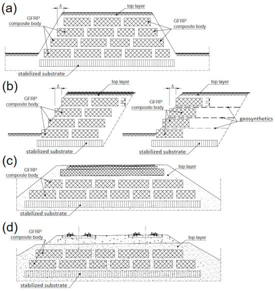
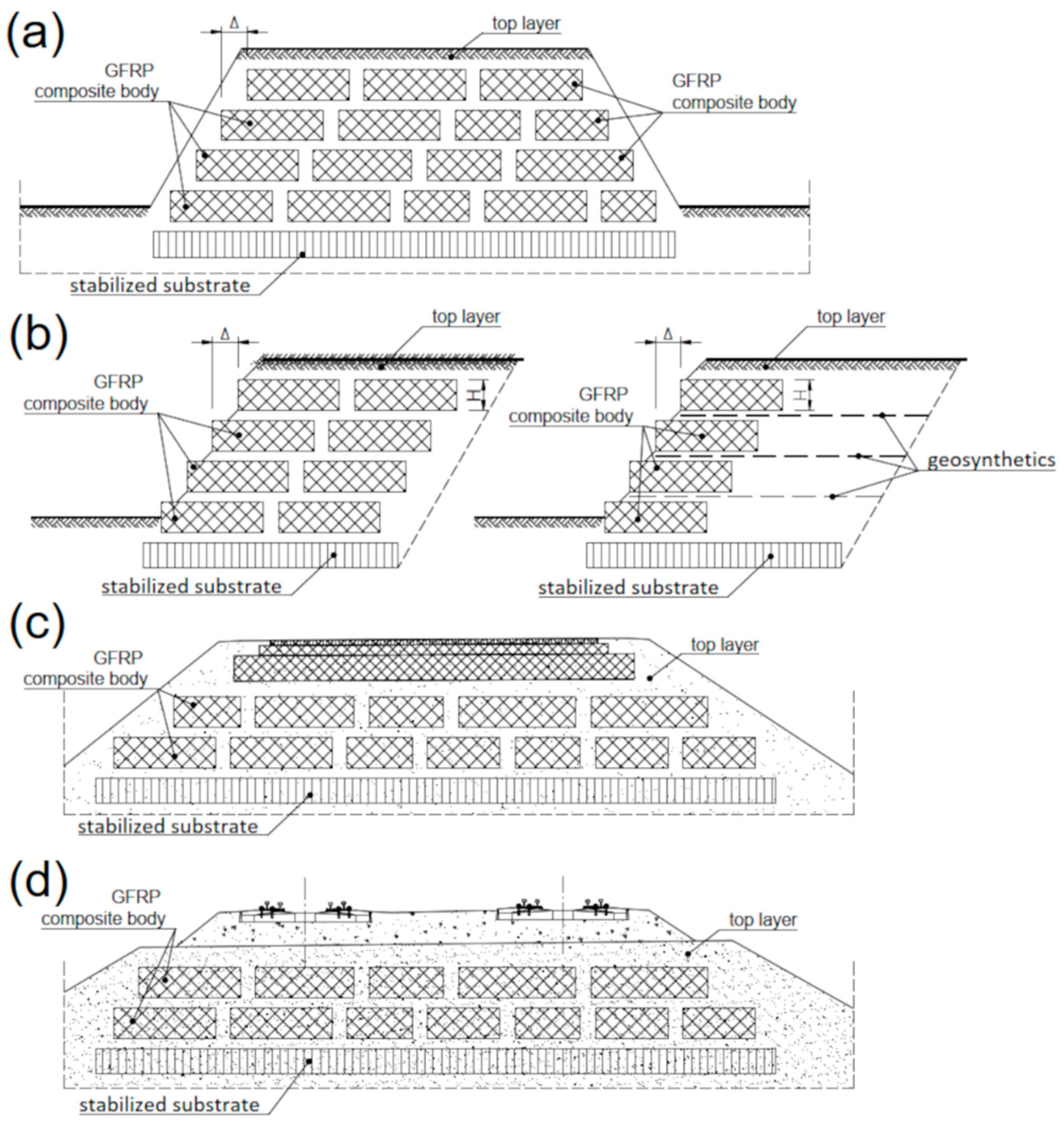
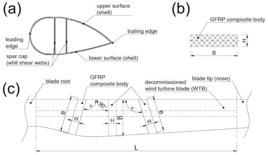
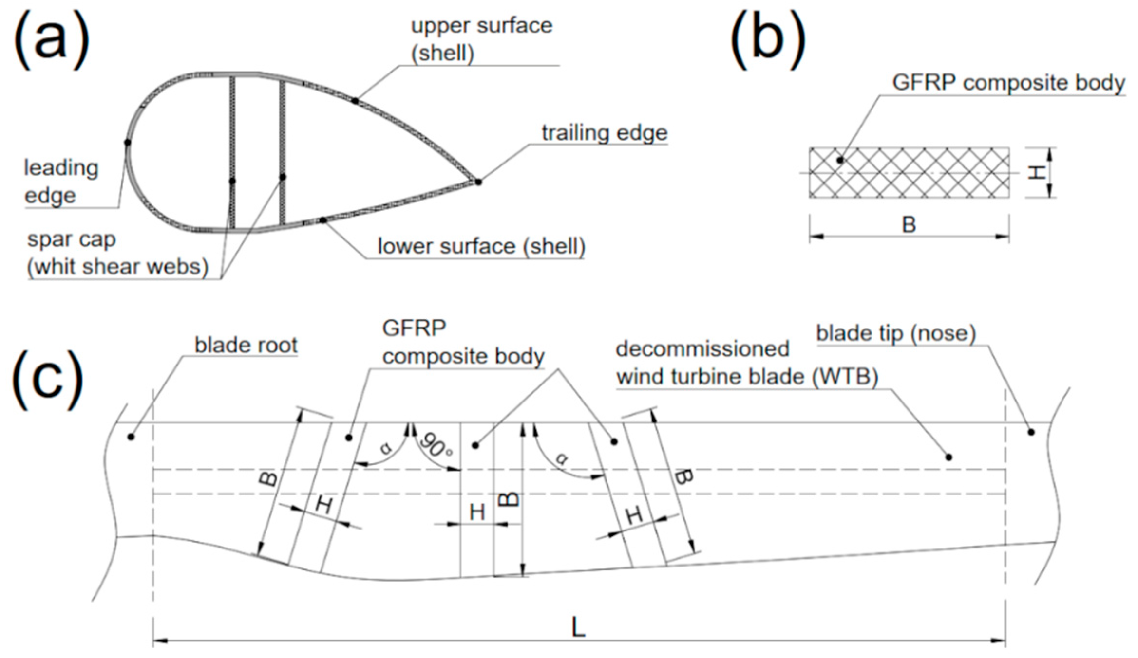
The main element of the retaining structure is a geotechnical block (hereinafter: WTB block) which can be used in the construction of various earth structures, including flood embankments, retaining structures, foundations for roads and railway tracks, and ground reinforcement (Figure 1). The WTB block is made of a GFRP composite unit, which is a section of a decommissioned wind turbine blade containing parts of the leading edge, trailing edge, and the upper and lower surfaces of the dWTB. The typical wall thickness of the GFRP composite unit ranges from 15 to 30 mm, depending on the section’s location along the blade’s length and the local stacking sequence of the blade. The GFRP composite unit is cut from the dWTB section between its base and nose into two parallel planes, which may be perpendicular or diagonal to the blade’s longitudinal axis (Figure 2). The GFRP composite unit is open at both top and bottom, with the aforementioned fragments of the dWTB forming its vertical side walls.
Figure 1.
Methods involving the use of WTB blocks for the construction of earth structures: (a) Flood embankment; (b) retaining structure; (c) road foundation; (d) railway track foundation.
Figure 2.
GFRP composite unit of the WTB geotechnical block: (a) Top view; (b) side view; (c) the cutting plane of the blade to make the body.
The GFRP unit is filled with lightweight material. The fill for the WTB block should be non-cohesive and coarse-grained, with a high internal friction angle (usually not less than 30°), consistent with standard requirements for granular backfills used in retaining structures. As long as it maintains these properties, the filling material can include various types of recycled materials, often mixed with typical sand. Filling of the GFRP unit with this material is performed at the construction site of the earthwork structure (here: the retaining structure), where the WTB blocks are placed.
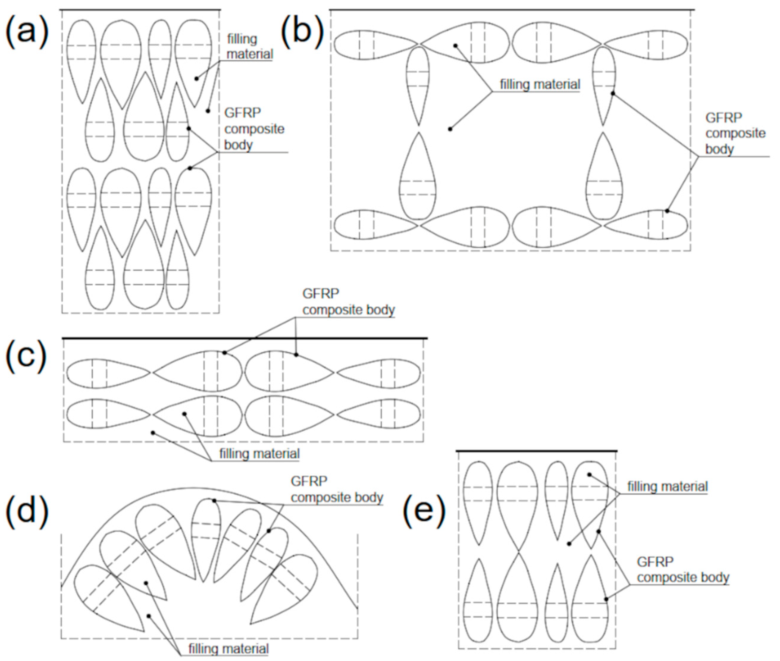
The construction of an earthwork structure using WTB blocks starts by placing at least one layer of GFRP composite units of equal height on stabilised ground. The arrangement of individual units within the layer and the external dimensions depend on the parameters of the designed earth structure (Figure 3). After placing all GFRP composite units in a layer, they are filled with filling material, raising it both inside and outside the units (i.e., between them) and, if the project requires, behind the retaining structure. In typical earthwork structures, at least two layers of WTB blocks are installed. Each subsequent layer is offset by approximately 0.3 m relative to the previous one, towards the soil massif. If the outer blocks of each layer also serve as the external cladding of the earthwork structure, these units should be filled with coarse-grained stone aggregate (or concrete) to provide adequate weight (gravity) to the structure. To enhance the structure’s load-bearing capacity and stability, it is beneficial to install a typical soil reinforcement made of geosynthetics between the WTB block layers (Figure 1b).
Figure 3.
Single-layer GFRP composite unit arrangements: (a) In equal rows alternately; (b) perpendicular to each other; (c) longitudinally; (d) in a curvilinear pattern; (e) transversely to the longitudinal axis.
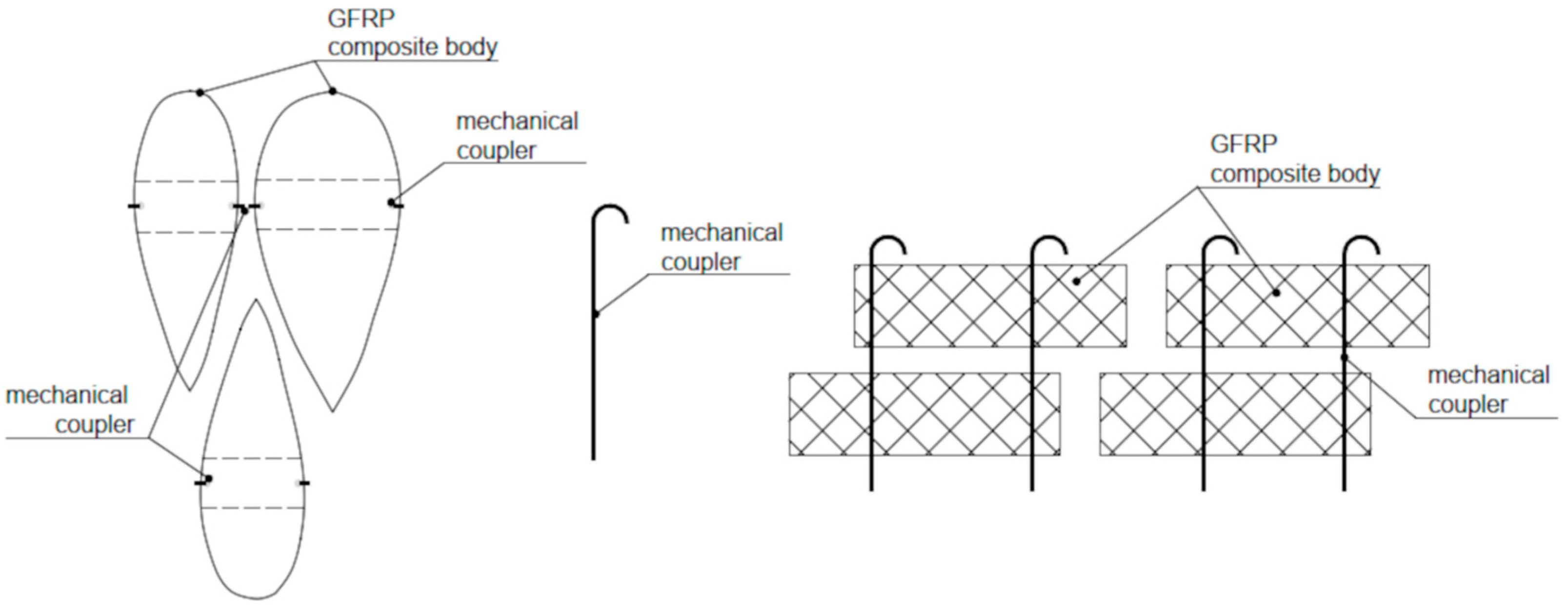
Even greater benefits can be achieved by connecting adjacent GFRP composite units with mechanical connectors before filling them. The modular WTB block system is based on dry joints between adjacent composite units, where load transfer is primarily ensured by direct contact, friction, and geometric interlocking between neighbouring segments. Mechanical connectors can be added as supplementary elements to enhance structural integrity, limit relative displacements, and improve long-term reliability under sustained loading. The interconnection of WTB blocks can be achieved using simple rod-type fasteners installed through pre-drilled holes or locally clamped between adjacent units, as shown schematically in Figure 4. These connectors may be made of structural steel or non-corrosive GFRP bars, and are mainly designed to resist local sliding, separation, or rotation at the contact interfaces. Anchoring and overlapping between successive block layers are achieved through the stepped arrangement of the blocks towards the soil massif, similar to conventional gabion retaining structures.
Figure 4.
Mechanical connections between GFRP composite units.
Under long-term loading conditions, the reliability of the joints mainly depends on the sustained contact pressure between blocks, the frictional resistance at the interfaces, and the durability of the connector materials. Potential failure modes at the joints include local sliding between adjacent blocks, progressive joint opening due to infill deformation, and connector yielding or pull-out under excessive loads. These failure mechanisms can be mitigated through the implementation of an appropriate block geometry, adequate block weight, conservative design assumptions and, when necessary, the use of mechanical connectors and geosynthetic reinforcement. Similarly to conventional gravity and gabion retaining structures, joint performance is evaluated within the context of both global and local stability checks, rather than at isolated structural connections.
Since the GFRP composite unit can be cut almost arbitrarily from a decommissioned wind turbine blade (dWTB) using cutting planes that are parallel to each other and either perpendicular or inclined relative to the blade’s longitudinal axis, it is possible to produce blocks of equal width. This width corresponds to the distance between the cutting planes, enabling the creation of systems with fixed block depths. Typical cut-out block widths range from roughly 0.5 to 1.5 metres, depending on the blade segment, local cross-sectional geometry, and handling requirements. The cutting technique mainly controls the dimensional tolerances of the cut blocks and is generally within ±10–20 mm, which is adequate for geotechnical applications.
The cutting process is performed using dedicated diamond or carbide-tipped saws suitable for fibre-reinforced polymer composites. During cutting, fine dust is produced as a by-product, which is collected using local extraction systems (e.g., blowers or industrial vacuum units). Personnel involved in processing and handling the blade segments must wear appropriate personal protective equipment, including respiratory protection. After cutting, individual blocks can be safely handled and positioned using light lifting equipment or manually handled by two operators, depending on size and weight of the blocks.
After processing, the WTB blocks do not need extra surface treatment before installation in earthwork structures. However, for retaining structures that are subject to higher loads or built to greater heights, additional reinforcement measures might be added. These include mechanical connectors between adjacent blocks, the use of non-corrosive GFRP or steel rod-fasteners, or the installation of geosynthetic reinforcement layers between block courses. Such measures follow design principles similar to those used for conventional gabion retaining structures and are applied only when necessary, based on loading and stability conditions.
Depending on the height of the retaining structure and the loading conditions, the WTB blocks in the system can be arranged in various manners. A summary of typical configurations, including the use of geosynthetics and mechanical connectors, is provided in Table 1.
Table 1.
Summary of design variants of the WTB retaining structure system.
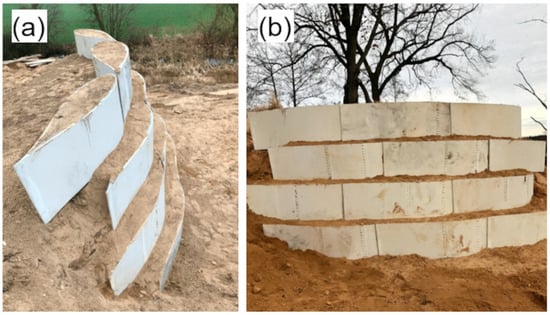
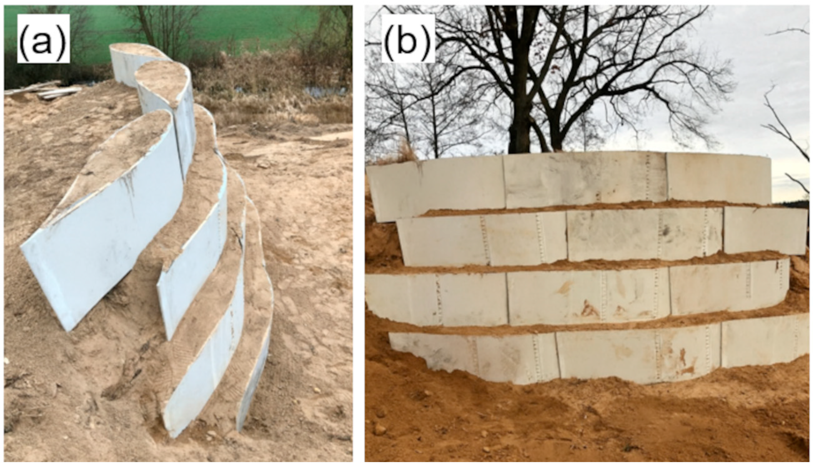
Geotechnical WTB blocks provide many benefits in earthworks applications. Firstly, they are characterised by lower surface and volume unit weights than concrete blocks or metal–stone gabions, which is a significant consideration in geotechnical projects, especially in areas with poor ground conditions. They also make it easier to construct earthwork structures, with the specific shape and size of the WTB blocks enabling their use and arrangement in various surface and spatial structure layouts (see Figure 2 and Figure 3). This enables the earthwork structure to be readily adapted to specific site conditions and technical requirements. In earthwork structures, the excellent material properties of the GFRP composite, combined with the advantageous geometry of the WTB blocks, ensure the high rigidity, load-bearing capacity, and stability of each block and the entire earthwork structure, enabling more effective design with these blocks. Figure 5 illustrates the application of WTB geotechnical blocks to construct a retaining structure for preliminary testing.
Figure 5.
Prototype retaining structure constructed from WTB blocks: (a) Top view showing the stepped arrangement of GFRP units; (b) front view illustrating the multi-layer configuration of the assembled retaining system.
From a long-term performance perspective, GFRP composites are generally considered corrosion-resistant; however, their mechanical properties may deteriorate under certain environmental conditions [35]. In geotechnical applications, potential degradation mechanisms include moisture penetration into the polymer matrix (causing plasticisation and stiffness changes), hygrothermal cycling (temperature variations combined with moisture), and prolonged chemical interactions with soil pore water (e.g., differing pH levels, sulphates, chlorides, and organic compounds), which can lead to matrix hydrolysis or weakening of the fibre–matrix interface. Additionally, surface abrasion during handling and installation may locally damage the resin-rich layer and speed up moisture ingress. UV radiation mainly affects storage and handling before installation; once buried, the composite is largely protected from direct UV exposure. These durability aspects have been discussed in the literature for FRP composites used in civil infrastructure and for GFRP systems exposed to moisture, thermal, and weathering effects [36]; thus, they should be considered in the long-term assessment of WTB-based retaining structures.
To increase the sustainability and economic efficiency of the new retaining structure, a special filling material that contains two of the recyclates under investigation in an ongoing R&D project (i.e., polymer foil and rubber powder) has been developed. Both recyclates were combined with typical sand in several predefined mass proportions, chosen to reflect realistic ranges for lightweight infill and backfill in retaining structures. Preliminary studies have shown that the use of a mixture of sand with these recyclates in earthworks has the following potential benefits:
- Increasing deformability and energy dissipation capacity (vibration damping, reduction in displacement amplitudes);
- Possibility of modifying the deformation characteristics, including reducing the brittleness of the granular system;
- Partial reduction in the volume density of the backfill, which may lead to a reduction in pressure on the retaining structure.
Compared to other recyclates used in soil mixtures (e.g., RCA, ashes, slags), the use of recycled plastic materials is poorly documented in the literature. The study of the mixtures including sand and both recyclates can therefore be seen as a development of current trends in using waste to modify earthworks.
From an economic perspective, the proposed WTB block retaining structure offers potential cost benefits compared to conventional retaining solutions. For reference, the typical cost of constructing stone-filled gabion retaining structures is around EUR 150–160 per cubic metre of wall volume, with the stone infill alone accounting for about EUR 80 per cubic metre. In contrast, supplier data for processed WTB composite blocks indicate that recycled blade-derived units cost approximately EUR 40–50 per cubic metre, including transport. The infill for WTB blocks may be made from locally available soil or non-cohesive sand, usually costing around EUR 15–25 per cubic metre.
Consequently, the implementation of a WTB block retaining structure may lead to a reduction of approximately EUR 15–30 per cubic metre in material costs, when compared to traditional gabion systems (subject to local conditions and material availability). Further savings may be obtained during construction, as WTB blocks are easier to handle and position with lightweight equipment or manual labour, and the filling and compaction processes also require less labour than those for stone-filled gabions.
From a simplified life-cycle cost perspective, reusing decommissioned wind turbine blades lowers raw material use, waste management and disposal expenses, and the environmental impacts associated with producing new construction materials. Although a detailed life-cycle cost analysis is beyond the scope of this study, the proposed approach shows advantageous qualities in terms of initial material costs, ease of construction, and potential environmental advantages throughout the service life of the retaining structure.
3. Materials and Methods
3.1. GFRP Composite Units
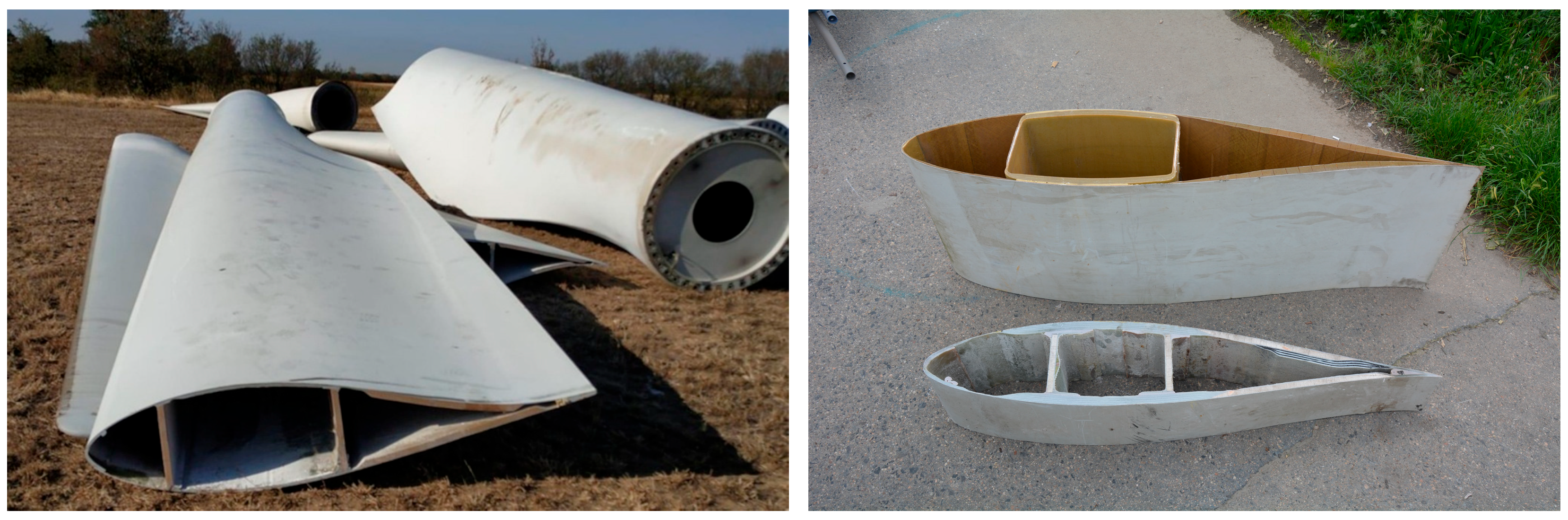
The main part of the geotechnical block is a GFRP composite unit: a section of a decommissioned wind turbine blade (Figure 6). The current research and implementation project focuses on the LM 29.1 blade, produced by LM Wind Power (Kolding, Denmark), which was decommissioned after about 20 years of service. A single LM 29.1 blade has a total length of 30 m, and its edge-oriented depth varies from 1.120 to 2.365 m. The blade is entirely made of E-glass fibres and an epoxy resin matrix. The cross-section of the blade comprises three major subcomponents: the shell (the skin that defines the airfoil’s shape), the spar cap (the primary load-carrying component), and the internal webs (components that support shear and buckling). The shell and webs are made of sandwich composites, whereas the spar cap is made of solid composites. In this case, the leading edge of the airfoil is also made of solid composites.
Figure 6.
The decommissioned wind turbine blades LM 29.1 (left) and various GFRP composite units for use as geotechnical blocks (right).
The overall dimensions of the blade were established through terrestrial laser scanning (TLS). TLS measurements were conducted outdoors to capture the whole geometry of the LM 29.1 blade using the Surphaser 25hsx (Laserscanning Europe GmbH, Magdeburg, Germany) a phase-shift scanner. The open-source CloudCompare (v.2.13.2) and Geomagic Studio (v. 2020.0.0+) software were employed for post-processing the data and mapping the results. The dWTB inventory data were then used for 3D design of the retaining structure to be implemented on site.
To obtain the material data required for the design of the GFRP geotechnical block, a material testing programme was developed for the main components, namely, the GFRP composite unit and the two filling materials. In the first case, the tests comprised the main WTB components from both leading and trailing edges, two composite types (solid, sandwich), and three laminate directions (longitudinal, transverse, and 45°). Moreover, specimens were extracted from the components located on both the pressure and suction sides of the blade. For sandwich composites, foam-core tests were omitted as this material has no effect on the structure’s load-bearing capacity and, thus, is usually neglected in design. To determine the stacking sequence and fibre volume fractions of the GFRP laminates, a resin burnout test was also conducted. The final GFRP material parameters are detailed in Table 2, while the complete material testing programme has been described elsewhere [37].
Table 2.
Basic material parameters of the LM 29.1 decommissioned wind turbine blade.
3.2. Filling Material with PVA/PVB Recyclate
The first material was a recycled laminated glass waste material, which is a specific mixture of PVA and/or PVB polymer fibres and/or flakes. PVA (polyvinyl alcohol) and PVB (polyvinyl butyral) polymers are widely used as technical films in the packaging and construction industries and as interlayers in laminated glass such as automotive and façade glass, among other applications. Only a small part of the used glass material is recycled due to contamination with glass shards, varying humidity, and variations in the film’s chemical composition. A typical recyclate contains about 80% PVA/PVB film, max. 15% glass, and max. 5% of other impurities. The PVA/PVB film recyclate is produced via R3 or R12 processes by waste management entities and is identified with the code 191204.
The recycled PVB/PVA foil was introduced into the sand as irregular flat flakes. Typical particle dimensions were 5–30 mm in length and 3–20 mm in width, with the original foil thickness of approximately 0.4–0.8 mm. The recycled PVB/PVA pieces can be characterised as flat polymer lamellae with relatively low aspect ratios, rather than traditional slender fibres, which influences their interaction with the granular material matrix. Thin and ductile polymer lamellae act as short, dispersed reinforcement, capable of transferring tensile stresses and dissipating energy in local strain zones. Durable and lightweight PVA/PVB recyclates are characterised by good flexibility, high adhesion to various materials, and water resistance. They do not undergo biological or chemical decomposition, and their melting points range from 135 to 210 °C. A low glass content (up to 15%) increases the lamellae’s surface roughness, thereby improving mechanical anchoring in the matrix (e.g., the ground). PVA/PVB recyclates can be utilised as dispersed reinforcement for macro-levelling mixtures, i.e., coarse-grained soils or soil–aggregate blends used for extensive ground levelling and formation layers, as well as for earth masses, earth–concrete mixtures, and soil stabilisation procedures.
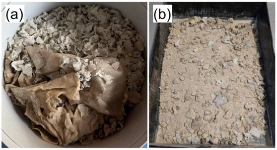
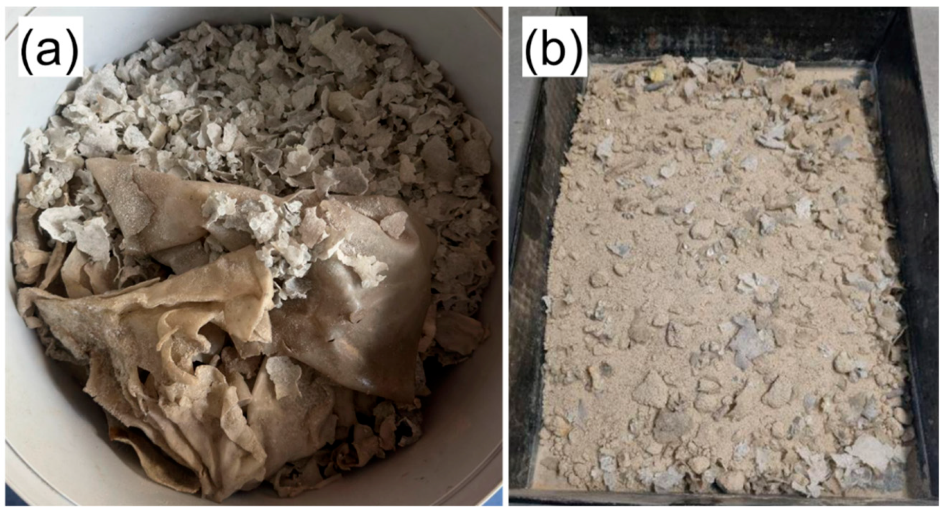
The PVB recyclate used in this research was delivered as irregular lamellae of various shapes (Figure 7a), ranging from thin, curled flakes measuring a few millimetres to larger, folded pieces measuring several centimetres. Before mixing, the material was manually homogenised by breaking oversized fragments to a size compatible with the sand’s particle size distribution. The mineral component consisted of clean medium sand. The mixtures were prepared by dry-blending predetermined amounts of sand and polymer recyclate. Mixing was performed manually in a flat container (Figure 7b) until the polymer fragments were evenly distributed. No water or chemical additives were introduced at this stage, as the goal was to examine the fundamental mechanical behaviours of the dry polymer–sand composites.
Figure 7.
Recyclate in the form of shredded PVB foil obtained from recycled laminated glass: (a) Raw recyclate; (b) a mixture of recyclate and standard sand.
During the preparation and filling of the small-scale direct shear box (60 mm × 60 mm), no pronounced segregation or preferential orientation of the recyclate particles was observed in mixtures with low to moderate polymer contents (up to 8% by dry mass). With higher PVB/PVA contents (16% and 32%), some local segregation and partial alignment of polymer lamellae were occasionally noticed during placement. This behaviour is mainly attributed to scale effects arising from the shear box’s small dimensions and the relatively large size and flexibility of the polymer flakes, and such effects are expected to be significantly diminished in larger-scale tests and field applications.
The improvement in shear strength observed in mixtures containing up to approximately 8% PVB/PVA can be attributed to a favourable balance between reinforcement efficiency and particle interactions. At this content, the flat polymer lamellae are sufficiently numerous to bridge sand grains, enhance interlocking, and mobilise additional tensile resistance without significantly disturbing the granular skeleton. Random orientation of the lamellae and the presence of glass inclusions further promote frictional resistance and mechanical wedging between particles. At higher PVB contents, the increasing proportion of polymer inclusions may locally disrupt grain-to-grain contacts, thereby reducing stress transfer and shear resistance.
The experimental programme was developed to evaluate how increasing the PVB recyclate content affects frictional resistance and shear strength. Considering potential field applications in earthwork structures, six PVB recyclate contents (by dry mass) were chosen: 0% (reference sand), 2%, 4%, 8%, 16%, and 32%. This gradation aimed to achieve two main goals: to explore the relationship between recyclate content and shear resistance, including peak and residual strength; and to identify an optimal mixture for further testing in large-scale shear boxes (300 mm × 300 mm) that simulate the behaviour of earthwork structures.
3.3. Filling Material with Rubber Powder
Rubber particles are known to increase the compressibility of granular mixtures, reduce their unit weight, and consequently lessen active earth pressures. They significantly enhance damping due to the intrinsic viscoelasticity of Styrene-Butadiene Rubber (SBR) and Nitrile Butadiene Rubber (NBR) and promote energy dissipation through inter-particle sliding and deformation. Additionally, they improve post-peak stiffness degradation and residual strength behaviours. Given its excellent particle size distribution, it was anticipated that rubber powder would interact at the microscale to modify the frictional response of sand, with a 10–20% content potentially providing enhanced ductility and stable residual shear behaviour.
The lightweight component used in the tested mixtures was Gummi NM-Pulver, a halogen-free rubber microgranulate obtained through mechanical shredding of post-consumer tyres. According to the product data sheet, the material is based on sulphur-crosslinked SBR and NBR elastomers and contains mineral fillers and silica. It is free from carcinogenic N-nitrosamines and does not contain aggressive plasticisers, which is relevant for geotechnical applications, particularly those where leaching and environmental compatibility must be considered.
The recyclate was supplied as a fine powder of mixed colouration, with very low moisture content (~0.6%) and a bulk density of approx. 350 g/L. The material is characterised by an excellent gradation, as shown in the sieve analysis reproduced from the data sheet. Key fractions include: 48.5% passing the 125 μm sieve, 21.0% passing 90 μm, 15.7% passing 45 μm, 8.0% passing 250 μm, and only 0.7% retained above 500 μm. This means that over 83% of the material is finer than 90 µm, and 99.4% is finer than 45 µm. Such a fine texture ensures excellent dispersion within the sand matrix, promoting the formation of numerous micro-contacts between rubber particles and mineral grains. According to manufacturer-conducted material tests, the rubber recyclate shows a loss on ignition of ~45%, primarily associated with the organic elastomeric phase. The acetone extract at ~4% indicates negligible residual plasticisers.
Based on the technical parameters and the known behaviours of rubber–sand mixtures, the importance of material properties for geotechnical applications was confirmed. The very low bulk density considerably reduces the unit weight of the backfill, thus decreasing earth pressures behind retaining structures. The elastomeric structure of SBR/NBR offers high damping capacity, improving the mixture’s ability to absorb cyclic energy. Fine rubber particles partly behave like short, flexible inclusions, increasing ductility and post-peak deformation capacity. Additionally, the absence of hazardous components (halogens, nitrosamines) enhances environmental safety, allowing the use of rubber–sand mixtures in earthworks and embankments where groundwater contact may occur.
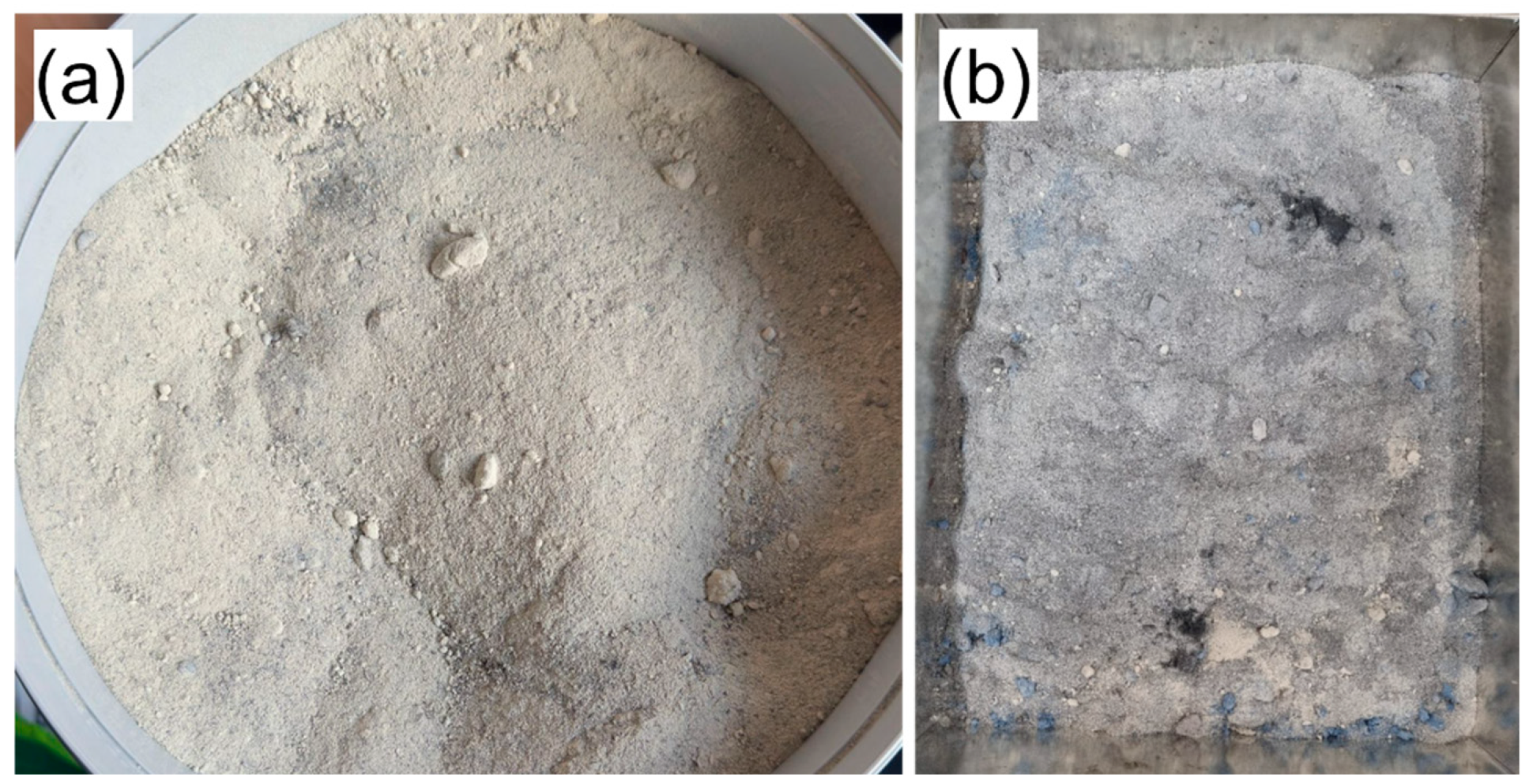
The sand–rubber mixtures were prepared as follows (Figure 8). The mineral component was clean medium sand, serving as the granular skeleton of the composite. Mixing was performed in dry conditions to isolate the intrinsic mechanical response of the rubber-reinforced material. Predetermined quantities of sand and rubber powder were combined in a flat mixing container and homogenised manually until evenly mixed. No water or chemical additives were added at this stage. This procedure mirrors the earlier methodology for mixtures modified with PVB/PVA recyclate, ensuring comparable results across the different waste-derived modifiers.
Figure 8.
Recyclate in the form of rubber powder obtained from shredded waste tyres: (a) Raw rubber powder; (b) mixture of rubber recyclate and standard sand.
The experimental programme aimed to assess how increasing the rubber content influences soil frictional resistance. Four levels of rubber modification were chosen (by dry mass): 0% (reference sand), 5%, 10%, and 20%. These proportions represent typical ranges for rubber–sand composites used in geotechnical applications as lightweight backfills, vibration damping layers, and reinforced earth. The main goals of this gradation were to measure the effects of rubber content on peak shear stress, residual shear stress, friction angle, and apparent cohesion, as well as to evaluate the potential of rubber modification to enhance ductility, energy absorption, and post-peak behaviour—properties which are particularly important for retaining structures subjected to cyclic loading or deformation.
3.4. Testing Methods
The testing programme was designed to systematically assess how different recyclates affect the mechanical behaviours of granular soils. The dataset generated supports selection of the optimal recyclate content for geotechnical applications, developing new sustainable soil reinforcing materials, and exploring potential uses in the WTB block system for slope and landslide stabilisation, as well as other earthwork structures.
The primary aim of the material tests was to identify the shear strength parameters of the filling mixtures, specifically, the peak shear stress (τp), residual shear stress (τr), friction angle (φ), and apparent cohesion (c). These parameters were chosen because they directly influence the performance of reinforced soils used in retaining structures, slope stabilisation, embankments, and gabion systems. In particular, PVB/PVA lamellas may function similarly to flexible polymer fibres, improving resistance through mechanical interlocking, friction, and energy dissipation. Additionally, filling mixtures with high ductility and enhanced post-peak behaviour are advantageous in structures subjected to cyclic loads or deformation, such as landslides or geotechnical barriers. Ultimately, understanding how the friction angle evolves with polymer addition is crucial for stability modelling and designing protective structures that incorporate recycled polymer waste.
The mechanical characteristics of the mixtures were assessed using a direct shear test, following the standards [38,39] (when applicable). For each mixture, normal stresses were applied at levels typical of geotechnical applications. Shear resistance was determined from peak and residual shear stresses. Testing was carried out using a standard direct shear apparatus with a 60 mm × 60 mm shear box, which is suitable for small-scale, preliminary mechanical characterisation, enabling controlled normal loading and displacement-driven shearing. However, we intend to employ a larger-scale direct shear apparatus (300 mm × 300 mm) in later stages for the most promising mixtures, as this can better simulate field behaviours, particularly for materials containing large recyclate fragments.
The applied normal stress levels in the direct shear tests were selected to reflect typical stress conditions within the infill and backfill of gravity retaining structures of moderate height. The considered range of normal stresses corresponds to vertical stresses caused by the self-weight of the overburden and retained soil at relevant depths for the analysed retaining wall configuration. Such stress levels are commonly used in laboratory studies on granular and lightweight backfills and enable meaningful assessment of peak and residual shear behaviours under conditions relevant to practical applications. A similar rationale for choosing normal stress levels has been effectively employed by the authors in previous experimental studies on lightweight backfills for retaining structures [16].
4. Results
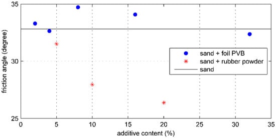
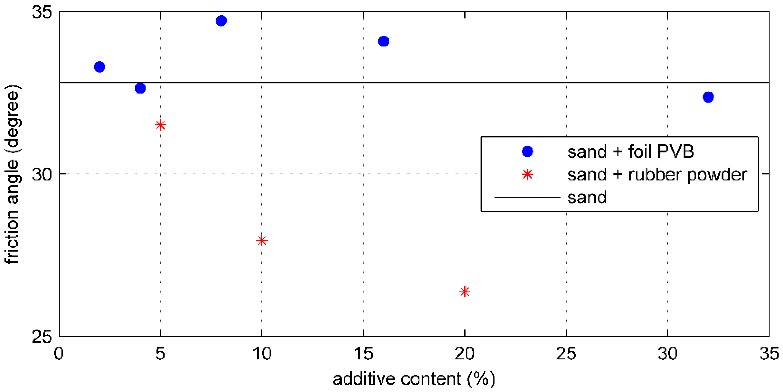
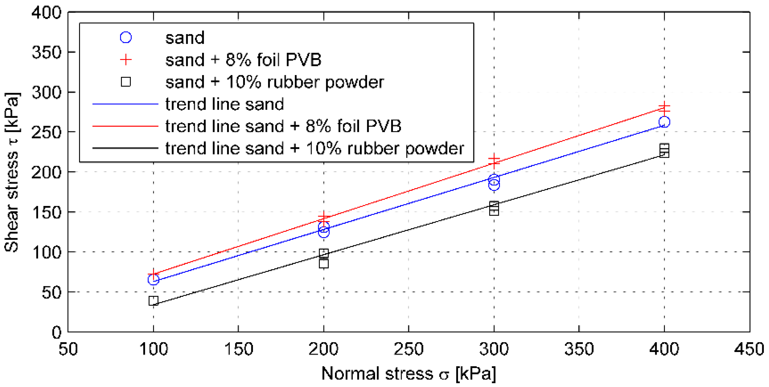
This section presents the results of direct shear tests conducted on the reference sand and mixtures of sand with recycled PVB foil and rubber powder. The study used a small-scale direct shear apparatus with box dimensions of 60 × 60 × 45 mm, and the parameters measured included peak shear stress values, the friction angle φ′, the cohesion c′, and the coefficient of determination R2 for the Mohr–Coulomb envelope. All results obtained through the shear tests are summarised in Table 3, while graphic presentations of results are provided in Figure 9 (friction angle vs. additive content) and Figure 10 (shear stress vs. normal stress).
Table 3.
Results of the direct shear tests.
Figure 9.
Relationship between the internal friction angle and the additive content for mixtures of sand with PVB foil (blue markers) and rubber powder (red markers); the horizontal line represents the friction angle of standard sand.
Figure 10.
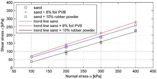
The relationships between shear stress and normal stress obtained through direct shear tests for standard sand and mixtures with recyclates.
The reference sand exhibited a friction angle of φ′ = 32.81° and a cohesion of c′ = 0 kPa, consistent with typical medium-density granular soils. The addition of PVB foil recyclate resulted in shear strength values that were equal to or better than those of the reference sand. As shown in Figure 9, nearly the entire PVB-mixed series remained above the reference sand’s friction angle, indicated by the reference line (level). The highest φ′ values were observed in mixtures containing 8% and 16% PVB, showing an increase of approximately 2° compared to the reference sand. The slightly lower value for the 4% mixture is likely due to measurement variation, as the PVB content was too low to alter the sand structure significantly. The shear envelopes in Figure 10 confirm these trends: the trend line for the 8% PVB mixture remained consistently above that of the reference sand across all applied normal stresses (100, 200, 300, 400 kPa), indicating a consistently higher shear resistance τ.
In contrast, mixtures containing rubber powder exhibited a notable decrease in the friction angle. As shown in Figure 9, all data points for rubber-added mixtures were below the reference sand line, with a particularly marked decline at contents of 10% and 15%. The shear envelopes in Figure 10 support this: at every normal stress, the τ–σ envelope for 10% rubber has the lowest slope, indicating a significant reduction in shear strength. These findings suggest that the use of rubber powder as a filling material for the proposed retaining structure may be limited under the tested conditions. However, it is essential to note that the observed behaviour is strongly influenced by scale effects arising from the small size of the direct shear box and the very fine particle size of the rubber powder. Therefore, these results should not be seen as evidence of the overall unsuitability of rubber-modified mixtures but, rather, as a sign that further research—including larger-scale laboratory tests and field validation—is necessary.
Furthermore, the favourable results obtained for the PVB–sand mixtures in the 60 mm shear box should also be interpreted cautiously due to potential scale effects. The PVB laminae used in the tests measured approximately 10–20 mm, indicating that their characteristic size is comparable to the shear box dimensions. In small apparatuses, such conditions may cause non-representative orientation or alignment of PVB laminae, artificial bridging or membrane-like effects, localised stiffening or weakening due to random arrangement, or a reduced ability of the sample to develop representative shear bands. For these reasons, we intend to validate the observed increase in shear strength using a larger-scale direct shear apparatus (300 × 300 × 150 mm). Such tests are necessary to eliminate scale-related influences from long PVB strips, confirm the reproducibility of τ–σ behaviours, obtain design values unaffected by sample-size artefacts, and enhance understanding of ductility and post-peak behaviours under full-scale conditions. Based on the obtained results, the chosen mixtures for upscaling were those containing 4% and 8% PVB, which represent the most promising combination of mechanical performance, mixing homogeneity, and practical feasibility.
5. WTB Block-Based Implementation Project
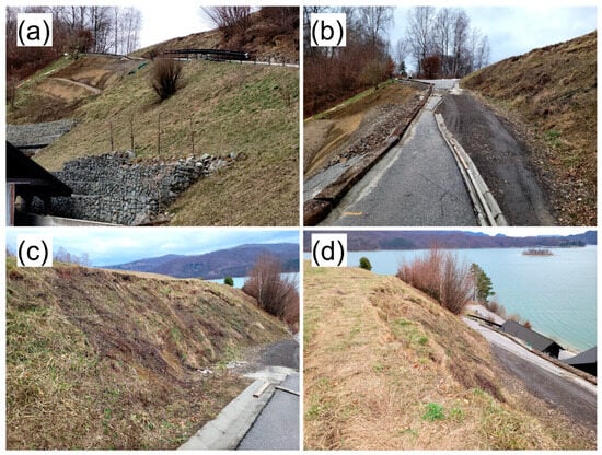
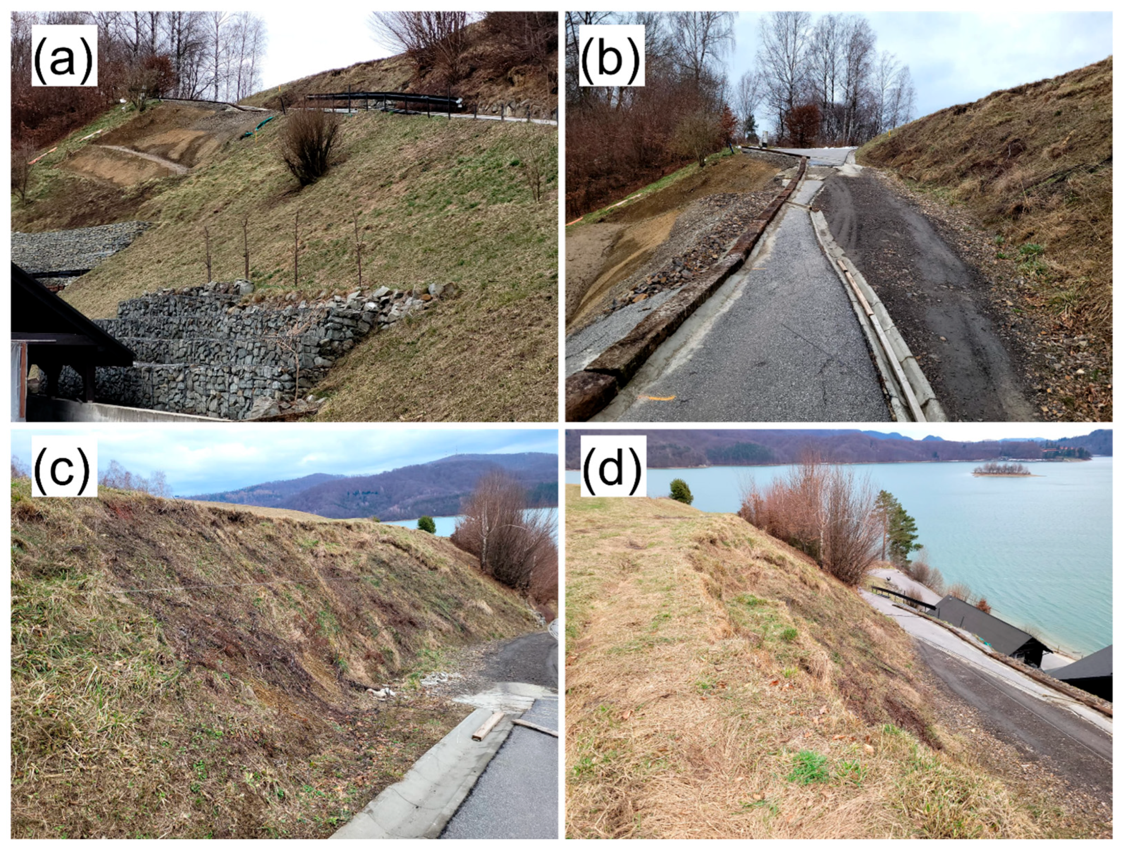
The subject of the implementation project was the protection of an active landslide in the town of Polańczyk in south-eastern Poland, covering approximately eight acres. This landslide has already been initially secured at its base with an anchored retaining wall made of steel and stone gabions. Above this retaining structure, there is a natural slope with a gradient of about 1:1.5 and a local road on the hill, which provides additional stabilisation through a horizontal ledge. Above the ledge, there is another slope with a gradient greater than 1:1.5. The total height of both parts of the landslide is approximately 20.5 m, including a 16 m lower part and a 4.5 m upper part (Figure 11).
Figure 11.
Existing condition of the landslide slope: (a) Gabion retaining structure at the landslide base; (b) damage to the road on the intermediate berm; (c,d) surface deformations and signs of instability on the upper slope.
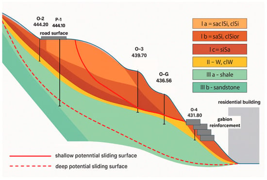
Geotechnical surveys were conducted in the landslide area, including seven boreholes. Three lithological systems of soil layers were identified within the landslide bed (Figure 12).
Figure 12.
Three lithological systems of soil layers identified within the landslide bed.
- Colluvial cohesive soils consisting of glacial and deluvial clays, silty clays, clay sands, and organic soils in a plastic or hard-plastic state (layers Ia, Ib, Ic).
- Weathered rock mass appearing as rubble mixed with silty sand, clay weathering, sandstone weathering, and slate clay weathering, all in a semi-compact state (layer II).
- Soft rock in the form of shale and sandstone of the Carpathian flysch (layers IIIa and IIIb).
Groundwater within the landslide-affected zone exhibits a discontinuous water table at depths ranging from 1.3 m to 3.5 m, primarily sourced from rainfall runoff from the areas above the landslide. Analysis based on the on-site inspection and findings from the geotechnical survey indicates that potential slip surfaces—either shallow or deep—may develop at the interface between layers II and III, or shallow within layer I.
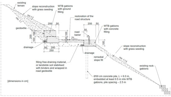
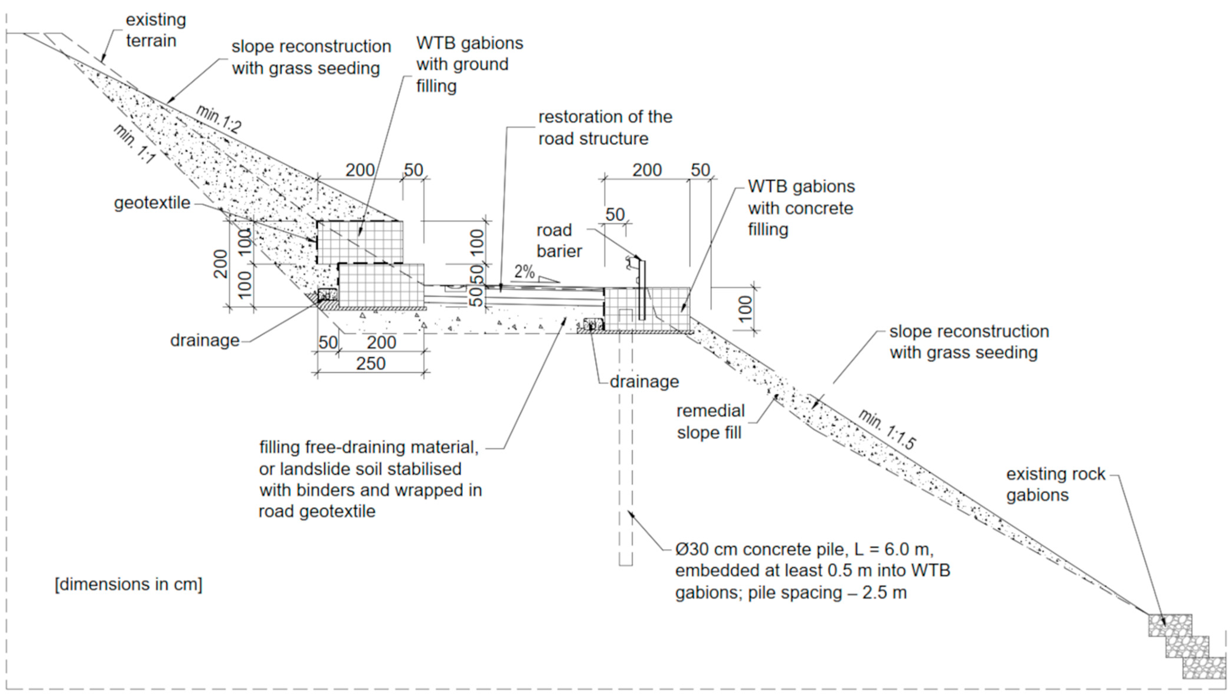
The new retaining structure was designed to protect against this landslide. It consists of self-supporting WTB geotechnical blocks mainly filled with a sand–PVB recyclate mixture, with localised concrete infill in the lowest and uppermost rows (Figure 13). In the enhanced design, the project includes a new lower anchored WTB block retaining structure, partly founded on rock and colluvium and secured with concrete piles; a new upper gravity WTB block structure situated above the local road; a reprofiled upper slope between the wall crest and the plateau, with a final inclination of 1:2; and local reformation of the intermediate slope between the new structure and the existing gabion structure at the base.
Figure 13.
Cross-section of the proposed landslide protection system using WTB blocks, drainage layers, stabilised fill, and concrete piles, integrated with the existing slope and road structure.
6. FE Analysis of Retaining Structure
Slope stability calculations were performed before and after strengthening, in accordance with the geotechnical design standard [40]. To evaluate the overall stability of the slope and to design the retaining structure, an approach based on characteristic geotechnical parameters and loads was employed. The required slope stability index for calculating the characteristic values of geotechnical parameters in landslide-prone terrain was set as FS ≥ 1.5. Characteristic design values of the above parameters were compiled from laboratory tests, in situ observations, and the authors’ experience with similar flysch formations in the Carpathian region. These values are summarised in Table 4 for the existing slope and strengthened configuration materials.
Table 4.
Soil and material parameters used for stability calculations.
In the calculation model, the WTB blocks are represented as massive gravity blocks with equivalent continuum properties. The equivalent unit weight γeq and stiffness Eeq were derived through volume-weighted averaging of the infill and GFRP composite contributions, while assuming a relatively high cohesion and friction angle to reflect the interlock of the granular/soil infill within the closed composite body. Due to their significantly higher stiffness compared to the surrounding soils, the blocks were assumed to behave as quasi-rigid units, primarily mobilising base sliding and overturning rather than internal deformations. The yield parameters for the WTB geotechnical blocks, including the internal friction angle, were determined based on tests of the filling material (a mixture of sand and PVB recyclate), considering their low cohesion, to ensure local stability of the calculation model. One groundwater regime was considered: a high water table intersecting the slope, corresponding to an unfavourable scenario with drainage malfunction. The phreatic line in the latter case followed the interpretation from the borehole data and intersected the hill above the road level.
The numerical analyses were conducted using the geotechnical software suite GEO5 (Fine Software, Prague, Czech Republic). All soil and rock layers were modelled as linearly elastic–perfectly plastic materials governed by the Mohr–Coulomb failure criterion. For each layer, the following fundamental parameters were set: unit weight γ, Young’s modulus E, Poisson’s ratio ν, effective cohesion c′, and effective internal friction angle φ′ (Table 1). For the comparative numerical study, characteristic values were used directly in the calculations. For all soil–structure contacts, a “hard” regular contact was assumed, while the shear strength along the contacts followed the same Mohr–Coulomb law as the adjacent soil, which is a conservative assumption for the WTB blocks resting directly on rock or compacted colluvium.
The concrete piles supporting the lower retaining structure were modelled as beam elements with linear–elastic behaviour. Their cross-sectional stiffness was determined using the geometric properties of a circular section with a diameter of 0.30 m and elastic modulus of concrete class C25/30. Pile–soil interactions were represented implicitly through the surrounding continuum, with no separate spring elements used. The base of the model was fixed in both vertical and horizontal directions. Conversely, the vertical lateral boundaries were fixed horizontally and free vertically, which is standard practice in 2D slope stability analyses.
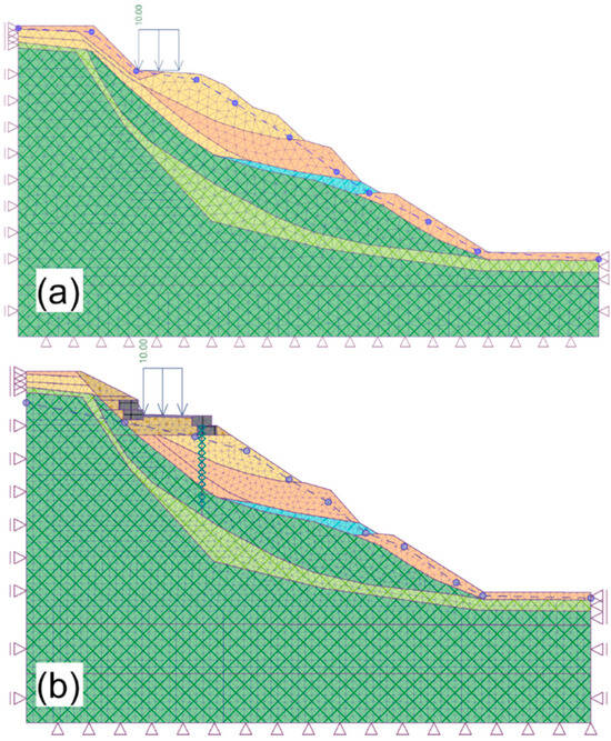
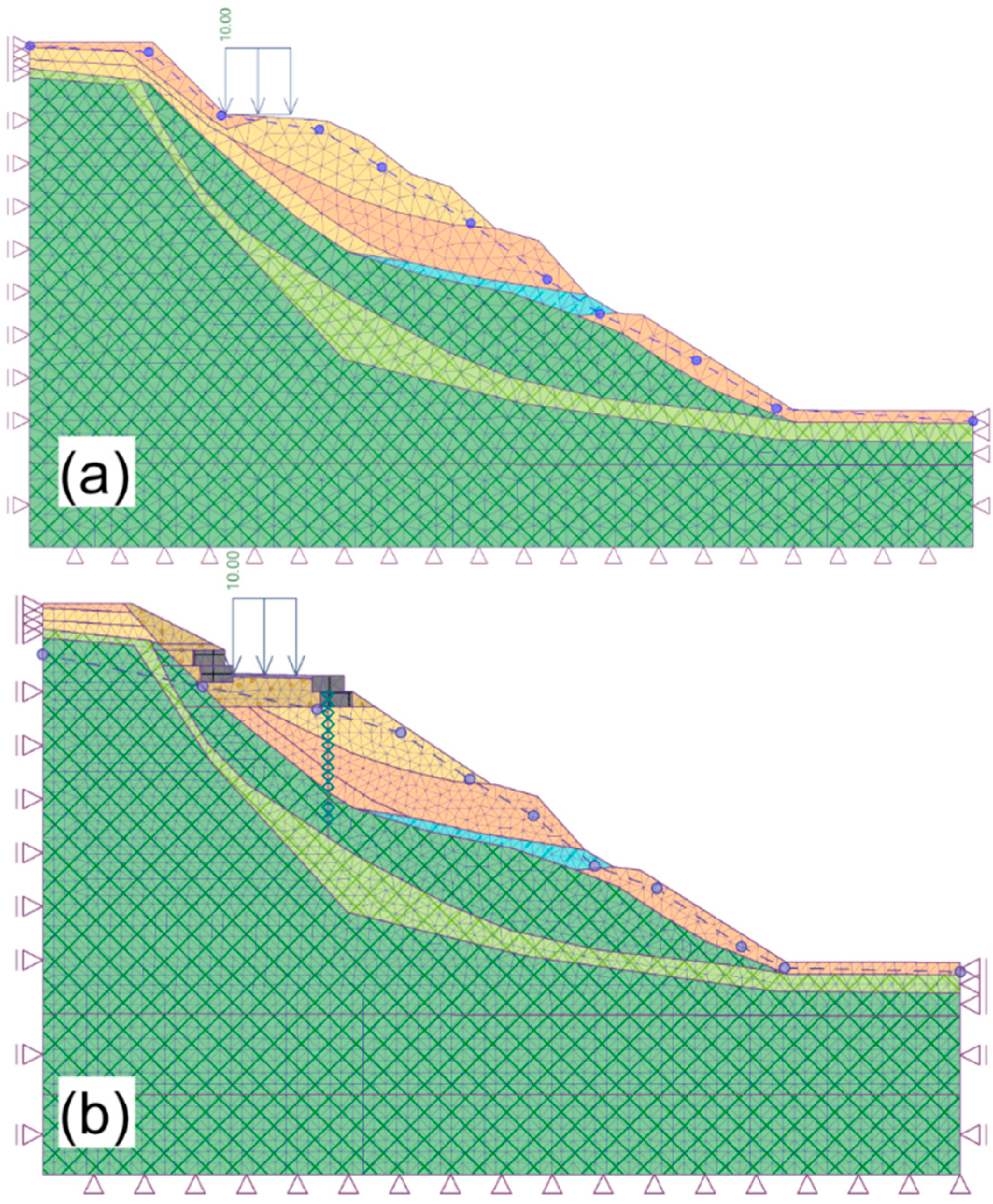
The two-dimensional numerical model replicated the longitudinal section A–A through the landslide slope, as outlined in the geotechnical survey (Figure 14). The model’s width was extended beyond the area of interest to minimise boundary effects, and the designated working area measured approximately 60 m across and 25 m in depth. The external loading consisted of the self-weight of all soil and structural components, along with a uniformly distributed surcharge of 10 kPa applied to the road surface, representing traffic loads from lightweight vehicles.
Figure 14.
Numerical model including the layer configuration: (a) Current condition; (b) strengthened condition.
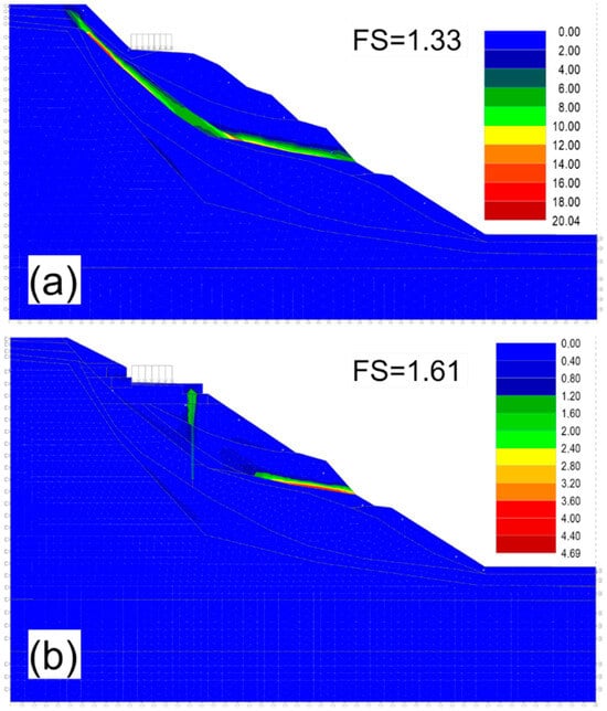
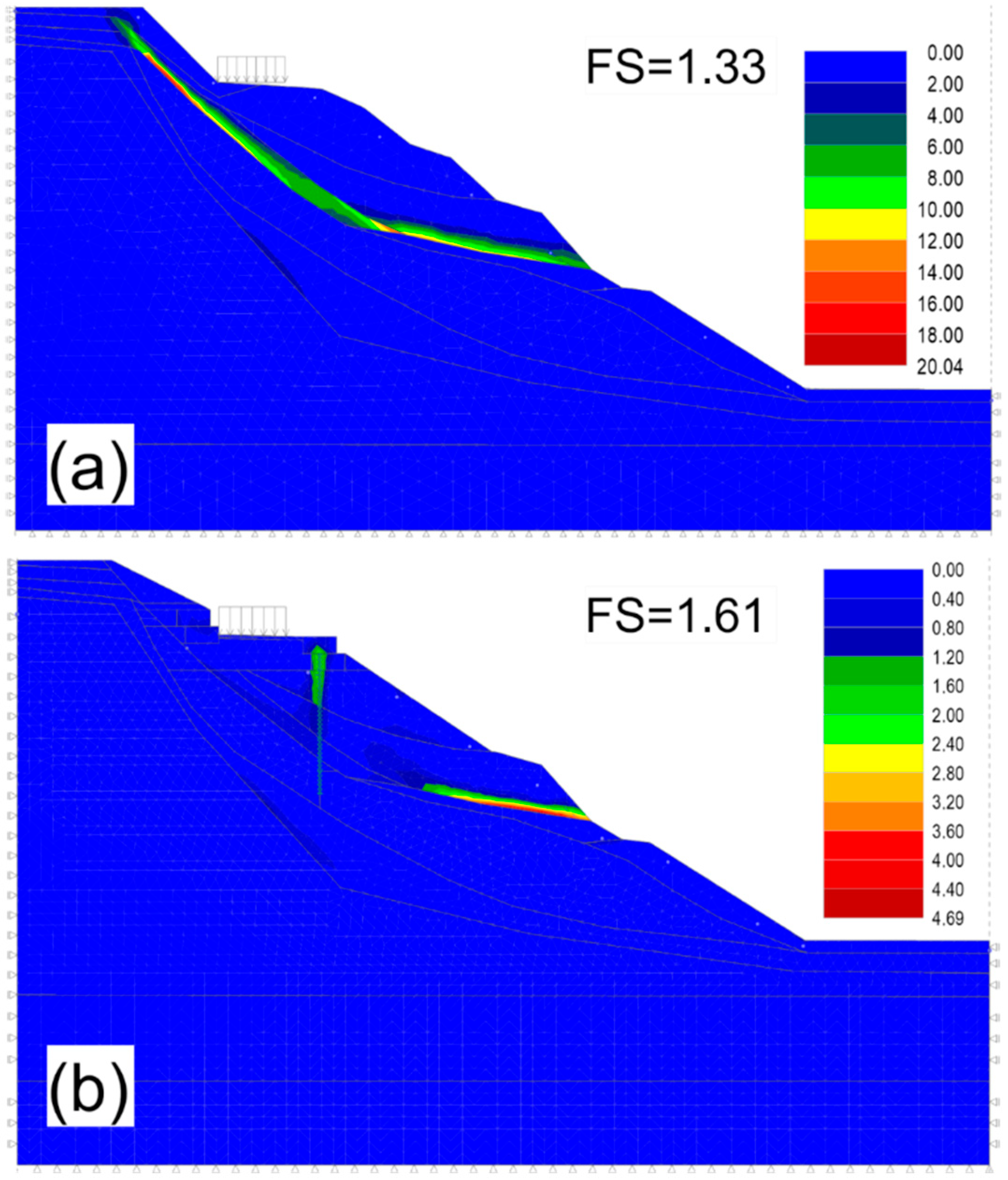
Slope stability was assessed in GEO5 using two complementary methods, similar to those previously used for lightweight tyre-bale embankments [14,15]. A finite-element (FE) analysis employing the strength-reduction technique was conducted in GEO5, in which Mohr–Coulomb material models were applied. Plane strain conditions were assumed, and the slope was discretised with a mesh of triangular and quadrilateral elements (Figure 14). The size of the finite elements was refined near the retaining structure and along the expected slip zones. A mesh sensitivity study was conducted to verify numerical stability, and further mesh refinement did not produce significant differences in the displacement or stress results. Convergence was considered to be achieved when successive load increments caused changes in key response parameters of less than a few percent. During the strength reduction process, the shear strength parameters (c′, tan φ′) of all soil and rock layers were uniformly reduced by a common factor until numerical non-convergence occurred, indicating global failure. The corresponding reduction factor was taken as the FE-based factor of safety, Fs,FE. The FE results were provided as displacement fields and plastic strain distributions within the slope and subsoil, enabling qualitative assessment of the deformation mechanisms and confirming that the new blade gabion structures effectively intercept and shorten the potential slip surface, thereby enhancing the overall stability of the landslide slope (Figure 15).
Figure 15.
Equivalent deviatoric plastic strain (%) with factor of safety and potential sliding surface: (a) Current condition; (b) strengthened condition.
Comparison of the equivalent deviatoric plastic strain plots for the existing and strengthened configurations revealed an apparent change in the failure mechanism. In the strengthened state, the potential slip surface is interrupted and narrowed by the WTB block structures: plastic strains are locally concentrated around the structures and at the slope base, while the upper slope and road platform mainly remain within the elastic range. This confirms that the new retaining system effectively controls both rotational and translational components of the landslide. The analyses indicate that the high stiffness of the WTB block structures and the anchoring effect of the concrete piles at the lower wall provide a combined stabilising action: the walls act as gravity structures, while the piles limit horizontal displacements and prevent forward movement towards the base. The observed deformation patterns indicate no concentration of plastic strains within the WTB blocks themselves, which behave quasi-rigidly and transfer loads safely into the underlying weathered and soft rock layers. For several layers—including the WTB gabion material, road surface, and remedial slope fill—unfavourable values of strength and stiffness parameters were deliberately used in the numerical model. Even with these conservative assumptions, the strengthened configuration achieved a safety factor greater than 1.5, indicating that the proposed solution is robust to reasonable uncertainties in geotechnical parameters.
Like any other retaining structure, a WTB block system must be assessed for stability against sliding, overturning, bearing capacity failure, and other issues, under both static and dynamic conditions. Therefore, it is essential to understand the behaviours of these highly complex structures under dynamic or seismic loading, which may be achieved through the evaluation of acceleration, displacement, and dynamic stress responses at various heights of the wall [41]. Typically, in the absence of full-scale dynamic testing, a series of shaking table tests is conducted to examine the dynamic performance and working mechanism of a retaining wall under dynamic/seismic loading [42]. Subsequently, a finite element analysis is performed to simulate the observed behaviour of the gabion retaining wall in shake table tests. Therefore, a full-scale shake table test of a gabion wall with backfill can be replicated numerically using the developed model. Finally, fatigue load tests are conducted on gabion retaining walls under varying cyclic loads to assess wall and reinforcement deformations [43]. All of these tests and analyses are planned as part of the development of the proposed WTB system, alongside monitoring of the constructed structure under vehicle static/dynamic loads and environmental impacts.
7. Conclusions and Further Works
This study introduced a new concept for landslide slope stabilisation based on the implementation of a gabion-type gravity retaining structure constructed from decommissioned wind turbine blade (WTB)-derived composite units and recycled infill materials. Laboratory material testing combined with finite element (FE) analysis confirmed that the proposed WTB geotechnical blocks can be effectively utilised in gravity retaining structures for landslide mitigation. In addition to meeting technical requirements for slope stability and deformation control, the proposed solution also supports circular economy goals by promoting the reuse of composite blades and scrap materials that are otherwise difficult to dispose of.
The shear testing programme demonstrated that sand modified with recycled PVB foil maintained or improved upon the shear strength of the reference sand, with the most favourable behaviours observed for mixtures containing 8–16% PVB. In contrast, sand–rubber mixtures exhibited reduced frictional resistance at all tested contents, particularly at higher rubber proportions. The τ–σ envelopes clearly distinguished the mechanical responses of the two recyclates, indicating PVB foil to be more suitable as a structural filler modifier. In contrast, rubber powder may be more appropriate for applications requiring damping rather than load-bearing performance.
The FE analysis demonstrated that the WTB retaining structure can significantly enhance overall slope stability, achieving a safety factor well above the target value of FS > 1.5, even under adverse groundwater conditions. In particular, the presence of WTB blocks was found to alter the failure mechanism by shortening and intercepting the potential slip surface and decreasing plastic deformation zones. The observed stabilising effect results from the combined action of the WTB gravity blocks, infill material, piles, and subsoil, while the use of conservative modelling assumptions helped to verify the robustness of the proposed design.
Despite these promising results, the study has certain limitations. The material behaviours were assessed using small-scale shear tests, and larger-scale laboratory and field investigations are needed to further validate the performance of the considered recycled infill mixtures. Additionally, the numerical analysis was limited to a two-dimensional plane strain model with simplified constitutive assumptions. Future research should therefore include three-dimensional analyses of complex landslide geometries, long-term performance evaluations under cyclic environmental loading, and full-scale experimental testing of WTB block-based retaining structures. Moreover, accelerated ageing tests are recommended to quantify potential changes in stiffness and strength resulting from combined moisture–temperature exposure, wet–dry cycling, freeze–thaw cycles, and contact with chemically aggressive pore solutions representative of local soils. Such tests would support service life assessments and the calibration of material reduction factors for long-term design.
8. Patents
There is a patent resulting from the work reported in this manuscript: Patent No. PL 246458 B1. Block for Geotechnical Applications. Patent Office of the Republic of Poland, Warsaw, Poland, 2020.
Author Contributions
Conceptualisation, A.D.; methodology, A.D. and T.S.; software, A.D.; validation, A.D.; investigation, A.D. and T.S.; resources, T.S.; data curation, A.D.; writing—original draft preparation, A.D.; writing—review and editing, T.S.; visualisation, A.D.; supervision, T.S.; project administration, T.S.; funding acquisition, T.S. All authors have read and agreed to the published version of the manuscript.
Funding
This research was co-financed by the MINISTER OF SCIENCE AND HIGHER EDUCATION within the following R&D project: “Regional Centre of Excellence in Engineering for Quality of Life and Technology Development” within the framework of the “Regional Excellence Initiative” Program, grant number RID/SP/0032/2024/01.
Institutional Review Board Statement
Not applicable.
Informed Consent Statement
Not applicable.
Data Availability Statement
The original contributions presented in this study are included in the article. Further inquiries can be directed to the corresponding author.
Acknowledgments
The authors acknowledge the technical support and donation of materials for testing used in experiments, provided by Anmet Sp. z o.o. and WMB International Sp. z o.o., which is not covered by the author contribution or funding sections.
Conflicts of Interest
The authors declare no conflicts of interest.
Abbreviations
The following abbreviations are used in this manuscript:
| dWTB | Decommissioned Wind Turbine Blade |
| GFRP | Glass Fibre Reinforced Polymer |
| HDPE | High-Density Polyethene |
| NBR | Nitrile Butadiene Rubber |
| PVA | Polyvinyl Alcohol |
| PVB | Polyvinyl Butyral |
| RCA | Recycled Concrete Aggregate |
| SBR | Styrene-Butadiene Rubber |
| TDA | Tyre-derived Aggregate |
| TDP | Tyre-derived Product |
| TLS | Terrestrial Laser Scanning |
| WTB | Wind Turbine Blade |
| FE | Finite element |
| PP | Polypropylene |
References
- Johst, P.; Bühl, M.; Enderle, C.; Kupfer, R.; Modler, N.; Böhm, R. Forecasting Wind Turbine Blade Waste with Material Composition and Geographical Distribution: Methodology and Application to Germany. Resour. Conserv. Recycl. 2024, 211, 107876. [Google Scholar] [CrossRef] [Scilit]
- WindEurope. Circularity. Available online: https://windeurope.org/about-wind/circularity/ (accessed on 23 November 2025).
- Fraile, D.; Walsh, C. (Eds.) Accelerating Wind Turbine Blade Circularity: The Industry Commitment; WindEurope: Brussels, Belgium, 2020. [Google Scholar]
- The Re-Wind Network. Re-Wind Design Catalogue, 2nd ed.; Fall/Autumn 2022; The Re-Wind Network: Singapore, 2022; Available online: https://static1.squarespace.com/static/5b324c409772ae52fecb6698/t/636bd07125aeb5312a8e320e/1668010099748/Re-Wind+Design+Catalog+Fall+2022+Nov+9+2022+%28low+res%29.pdf (accessed on 23 November 2025).
- Sledzik, A.; Banach, M. Pro-Environmental Solutions in Architecture—The Problem of Decommissioned Wind Blades. Sustainability 2025, 17, 2963. [Google Scholar] [CrossRef] [Scilit]
- Joustra, J.; Flipsen, B.; Balkenende, R. Structural Reuse of High-End Composite Products: A Design Case Study on Wind Turbine Blades. Resour. Conserv. Recycl. 2021, 167, 105393. [Google Scholar] [CrossRef] [Scilit]
- Andre, A.; Kullberg, J.; Nygren, D.; Mattsson, C.; Nedev, G.; Haghani, R. Re-Use of Wind Turbine Blade for Construction and Infrastructure Applications. IOP Conf. Ser. Mater. Sci. Eng. 2020, 942, 012015. [Google Scholar] [CrossRef] [Scilit]
- Broniewicz, M.; Halicka, A.; Buda-Ozóg, L.; Broniewicz, F.; Nykiel, D.; Jabłonski, Ł. The Use of Wind Turbine Blades to Build Road Noise Barriers as an Example of a Circular Economy Model. Materials 2024, 17, 2048. [Google Scholar] [CrossRef] [Scilit]
- Halicka, A.; Buda-Ozóg, L.; Broniewicz, M.; Jabłonski, Ł.; Zieba, J.; Broniewicz, F. Interaction Between Concrete and FRP Laminate in Structural Members Composed of Reused Wind Turbine Blades Filled with Concrete. Materials 2024, 17, 6186. [Google Scholar] [CrossRef] [Scilit]
- Buda-Ozóg, L.; Halicka, A.; Broniewicz, M.; Zieba, J.; Nykiel, D.; Jabłonski, Ł.; Broniewicz, F. Experimental Study of Used Wind Turbine Blades for Their Reuse in Slope and Trench Protection. Materials 2024, 17, 4934. [Google Scholar] [CrossRef] [Scilit]
- Rajchel, M.; Kulpa, M.; Wiater, A.; Siwowski, T. Repurposing a Decommissioned Wind Turbine Blade for Bridge Construction: An Experimental Investigation. J. Compos. Constr. 2024, 29, 04024084. [Google Scholar] [CrossRef] [Scilit]
- Rajchel, M.; Kulpa, M.; Siwowski, T. Repurposing of FRP Composite Decommissioned Wind Turbine Blades in Bridge Construction. In Proceedings of the 12th International Conference on FRP Composites in Civil Engineering (CICE 2025), Lisbon, Portugal, 14–16 July 2025. [Google Scholar]
- Patent Office of the Republic of Poland. Block for Geotechnical Applications…. Patent PL 246458 B1. 2020. Available online: https://ewyszukiwarka.pue.uprp.gov.pl/search/pwp-details/P.435138 (accessed on 23 November 2025).
- Duda, A.; Siwowski, T. Pressure Evaluation of Bridge Abutment Backfill Made of Waste Tyre Bales and Shreds: Experimental and Numerical Study. Transp. Geotech. 2020, 24, 100366. [Google Scholar] [CrossRef] [Scilit]
- Duda, A.; Siwowski, T. Stability and Settlement Analysis of a Lightweight Embankment Filled with Waste Tyre Bales over Soft Ground. Transp. Infrastruct. Geotechnol. 2021, 9, 467–491. [Google Scholar] [CrossRef] [Scilit]
- Duda, A.; Siwowski, T. Experimental Study on Earth Pressure Reduction of Waste Tyre Bales Used as a Backfill for Rigid Retaining Structures. Stud. Geotech. Mech. 2021, 43, 411–424. [Google Scholar] [CrossRef] [Scilit]
- Duda, A.; Siwowski, T. Waste Tyre Bales in Road Engineering: An Overview of Applications. Arch. Civ. Eng. 2021, 67, 213–230. [Google Scholar] [CrossRef]
- Lee, J.H.; Salgado, R.; Bernal, A.; Lovell, C.W. Shredded Tires and Rubber–Sand as Lightweight Backfill. J. Geotech. Geoenviron. Eng. 1999, 125, 132–141. [Google Scholar] [CrossRef] [Scilit]
- Reddy, S.B.; Krishna, A.M. Recycled Tire Chips Mixed with Sand as Lightweight Backfill Material in Retaining Wall Applications: An Experimental Investigation. Int. J. Geosynth. Ground Eng. 2015, 1, 31. [Google Scholar] [CrossRef] [Scilit]
- Contreras-Marín, E.; Anguita-García, M.; Alonso-Guzmán, E.M.; Jaramillo-Morilla, A.; Mascort-Albea, E.J.; Romero-Hernández, R.; Soriano-Cuesta, C. Use of Granulated Rubber Tyre Waste as Lightweight Backfill Material for Retaining Walls. Appl. Sci. 2021, 11, 6159. [Google Scholar] [CrossRef] [Scilit]
- Lamba, P.; Kaur, D.P.; Raj, S.; Sorout, J. Recycling/Reuse of Plastic Waste as Construction Material for Sustainable Development: A Review. Environ. Sci. Pollut. Res. 2022, 29, 86156–86179. [Google Scholar] [CrossRef] [Scilit]
- Nyika, J.; Dinka, M. Recycling Plastic Waste Materials for Building and Construction Materials: A Mini-review. Mater. Today Proc. 2022, 62, 3257–3262. [Google Scholar] [CrossRef] [Scilit]
- Meegoda, J.N. Production of Segmental Retaining Wall Units from Recycled Mixed Glass and Plastic. In Geo-Frontiers 2011: Advances in Geotechnical Engineering; American Society of Civil Engineers: Reston, VA, USA, 2011; pp. 1335–1344. [Google Scholar] [CrossRef] [Scilit]
- Kumi-Larbi Jnr, A.; Mohammed, L.; Tagbor, T.A.; Tulashie, S.K.; Cheeseman, C. Recycling Waste Plastics into Plastic-Bonded Sand Interlocking Blocks for Wall Construction in Developing Countries. Sustainability 2023, 15, 16602. [Google Scholar] [CrossRef] [Scilit]
- Ahmed, S.; Ali, M. Development and Engineering Evaluation of Interlocking Hollow Blocks Made of Recycled Plastic for Mortar-Free Housing. Buildings 2025, 15, 2996. [Google Scholar] [CrossRef] [Scilit]
- Meng, Y.; Ling, T.C.; Mo, K.H. Recycling of Wastes for Value-Added Applications in Concrete Blocks: An Overview. Resour. Conserv. Recycl. 2018, 138, 298–312. [Google Scholar] [CrossRef] [Scilit]
- Edike, U.E.; Ameh, O.J.; Yohanna, H.S.; Osuizugbo, I.C.; Nduka, D.O. Mechanical Properties of Concrete Blocks Incorporating Recycled Waste Plastic. Mater. Circ. Econ. 2024, 6, 10. [Google Scholar] [CrossRef] [Scilit]
- Graettinger, A.J.; Johnson, P.W.; Sunkari, P.; Duke, M.C.; Effinger, J. Recycling of Plastic Bottles for Use as a Lightweight Geotechnical Material. Manag. Environ. Qual. 2005, 16, 658–669. [Google Scholar] [CrossRef] [Scilit]
- Hamza, S.K.; Varghese, R.; Sankar, N. Sustainable Utilization of Lightweight Waste Materials as Structural Fill for Geotechnical Applications. IOP Conf. Ser. Mater. Sci. Eng. 2021, 1114, 012034. [Google Scholar] [CrossRef] [Scilit]
- Kim, B.; Prezzi, M.; Salgado, R. Geotechnical Properties of Fly and Bottom Ash Mixtures for Use in Highway Embankments. J. Geotech. Geoenviron. Eng. 2005, 131, 914–924. [Google Scholar] [CrossRef] [Scilit]
- Arulrajah, A.; Disfani, M.M.; Maghoolpilehrood, F.; Horpibulsuk, S.; Udonchai, A.; Imteaz, M.; Du, Y.-J. Engineering and Environmental Properties of Foamed Recycled Glass as a Lightweight Engineering Material. J. Clean. Prod. 2015, 94, 369–375. [Google Scholar] [CrossRef] [Scilit]
- Swan, R.H., Jr.; Yeom, S.; Sjoblom, K.J.; Stark, T.D.; Filshill, A. Engineering Properties of Foamed Recycled Glass as a Lightweight Fill. In Geo-Chicago 2016; American Society of Civil Engineers: Reston, VA, USA, 2016. [Google Scholar] [CrossRef] [Scilit]
- Silva Vieira, C.; Pereira, P.M. Use of Recycled Construction and Demolition Materials in Geotechnical Applications: A Review. Resour. Conserv. Recycl. 2015, 103, 192–204. [Google Scholar] [CrossRef] [Scilit]
- Silva Vieira, C.; Pereira, P.M.; de Lurdes Lopes, M. Recycled Construction and Demolition Wastes as Filling Material for Geosynthetic Reinforced Structures: Interface Properties. J. Clean. Prod. 2016, 124, 299–311. [Google Scholar] [CrossRef] [Scilit]
- Davis, A.; Sims, D. Weathering of Polymers; Springer: London, UK, 1983; Available online: https://www.amazon.com/Weathering-Polymers-Davis/dp/0853342261 (accessed on 23 November 2025).
- Karbhari, V.M.; Chin, J.W.; Hunston, D.; Benmokrane, B.; Juska, T.; Morgan, R.; Lesko, J.J.; Sorathia, U.; Reynaud, D. Durability gap analysis for fiber-reinforced polymer composites in civil infrastructure. J. Compos. Constr. 2003, 7, 238–247. [Google Scholar] [CrossRef] [Scilit]
- Wiater, A.; Rajchel, M.; Siwowski, T. Material properties of FRP composites from various decommissioned wind turbine blades for structural repurposing. In Proceedings of the 12th International Conference on FRP Composites in Civil Engineering (CICE 2025), Lisbon, Portugal, 14–16 July 2025. [Google Scholar]
- EN ISO 17892-10:2018; Geotechnical Investigation and Testing—Laboratory Testing of Soil—Part 10: Direct Shear Tests. International Organization for Standardization: Geneva, Switzerland, 2018.
- ASTM D3080/D3080M-23; Standard Test Method for Direct Shear Test of Soils under Consolidated Drained Conditions. ASTM International: West Conshohocken, PA, USA, 2023.
- PN-EN 1997-1:2008; Eurocode 7: Geotechnical Design—Part 1: General Rules. Polish Committee for Standardisation: Warsaw, Poland, 2008.
- Yang, G.L.; Huang, X.J.; Lin, Y.L. Test study on engineering properties of gabion structures. In Advances in Environmental Geotechnics; Springer: Berlin/Heidelberg, Germany, 2010; pp. 805–811. [Google Scholar] [CrossRef] [Scilit]
- Cai, X.; Zhang, S.; Li, S.; Xu, H.; Huang, X.; Zhu, C.; Liu, X. Dynamic Characteristics of Reinforced Soil Retaining Wall with Composite Gabion Based on Time Domain Identification Method. Sustainability 2022, 14, 16321. [Google Scholar] [CrossRef] [Scilit]
- Mummadisingh, J.V.; Sengupta, A. Study of the dynamic performance of a gabion wall. Structures 2023, 50, 576–589. [Google Scholar] [CrossRef] [Scilit]




Disclaimer/Publisher’s Note: The statements, opinions and data contained in all publications are solely those of the individual author(s) and contributor(s) and not of MDPI and/or the editor(s). MDPI and/or the editor(s) disclaim responsibility for any injury to people or property resulting from any ideas, methods, instructions or products referred to in the content. |
© 2026 by the authors. Licensee MDPI, Basel, Switzerland. This article is an open access article distributed under the terms and conditions of the Creative Commons Attribution (CC BY) license.