


Abstract
This paper investigates harmonic compensation for an LCL-filtered cascaded H-bridge (CHB) STATCOM operating in medium-voltage distribution networks under grid-frequency deviations and nonlinear loads. A hybrid current control strategy is proposed by combining a deadbeat (DB) inner-current loop with a Thiran all-pass filter-based frequency-adaptive repetitive controller (FARC). Weighted average inductor current (WAIC) feedback is adopted to reduce the third-order LCL filter to an equivalent first-order plant, thereby simplifying the current loop design while retaining the dominant low-frequency dynamics. The Thiran all-pass fractional delay filter is then embedded in the repetitive controller to realize a noninteger-period internal model at a fixed sampling frequency. This enables the controller to maintain harmonic compensation accuracy when the grid frequency deviates from its nominal value. A 10 kV LCL-filtered CHB STATCOM model is developed in MATLAB/Simulink, and the proposed method is compared with a conventional repetitive controller (CRC) under nominal frequency, frequency drift, nonlinear loading, harmonic load-switching conditions and grid impedance variation. Simulation results show that the proposed controller reduces the grid-current THD from 4.35% to 3.88% at 50 Hz, from 5.20% to 2.37% at 49.6 Hz, and from 6.51% to 3.56% at 50.4 Hz. In the tested frequency range of 49.5–50.5 Hz, the proposed method also maintains the power factor close to unity. These quantitative results demonstrate improved frequency robustness, harmonic suppression, and current-tracking performance compared with the CRC scheme, indicating that the proposed method can enhance STATCOM-based power quality compensation and support more reliable and efficient operation of medium-voltage distribution networks.
1. Introduction
The increasing penetration of power electronic converters and nonlinear loads in distribution networks has intensified power quality problems, including current harmonics, resonance phenomena, and distorted grid currents. These issues become more critical in renewable-rich and distributed energy systems, where converter-interfaced sources and fluctuating operating conditions impose higher requirements on harmonic compensation and current control [1,2]. Cascaded H-bridge (CHB) STATCOM systems are widely used in medium-voltage distribution grids to provide reactive power support, regulate the voltage at the point of common coupling (PCC), and compensate for load-induced harmonics [3,4].
Compared with a conventional single-inductor (L) filter, an LCL filter provides much sharper attenuation of high-frequency switching components, which is particularly attractive for medium-voltage CHB STATCOM applications [5,6]. It is widely acknowledged that third-order LCL filters provide markedly superior attenuation of switching-induced high-frequency current harmonics compared with simple first-order L filters. However, the associated higher order dynamics substantially complicate the modeling and systematic design of inverter current control schemes [7,8]. Numerous current regulation strategies have been investigated for CHB STATCOM, including PI, PR, and deadbeat (DB) control schemes [9,10,11]. In practice, DB controllers tend to be highly sensitive to parameter uncertainties and unmodeled delays, whereas PI and PR regulators often exhibit limited effectiveness when confronted with complex and time-varying harmonic spectra.
Repetitive control (RC), which is based on the internal model principle, has been widely used for periodic signal tracking and harmonic compensation in grid-connected converters [12,13,14,15,16]. A conventional repetitive controller (CRC) can, in principle, track or reject a periodic signal whose period corresponds to an integer number of samples, i.e., , where is the sampling frequency and f is the fundamental grid frequency. However, in practical distribution networks, the grid frequency may drift from its nominal value. Under a fixed sampling frequency, this drift makes N a noninteger, causing the resonant peaks of the internal CRC model to deviate from the actual harmonic frequencies. In recent years, a variety of frequency-adaptive repetitive control (FARC) schemes have been proposed to preserve the harmonic suppression capability of grid-connected converters under grid frequency drift [17,18,19,20,21]. Integer-period retuning approaches update the RC period length as , which is easy to implement but only provides stepwise adaptation and may cause noticeable detuning of the resonant peaks when the frequency deviates slightly from the nominal value [22]. Fractional delay (FD)-based FARC employs Lagrange interpolation FIR filters to approximate the non-integer delay, achieving smooth frequency adaptation at a fixed sampling rate; however, a relatively high filter order is often required to obtain a sufficiently wide approximation bandwidth, which increases computation burden and may introduce undesirable magnitude ripple at higher frequencies [23,24,25]. Virtual variable sampling strategies emulate a variable sampling period inside the internal RC model and, thus, can track grid frequency variations accurately, but they rely on complicated data reindexing and are sensitive to noise in the frequency estimate [26]. Fractional-order RC schemes further generalize the internal model but at the cost of more involved design and analysis, and their industrial adoption remains limited [21].
The novelty of this work does not lie in proposing WAIC, DB control, or fractional delay filtering as isolated techniques; rather, it lies in constructing a control-oriented combination of these techniques for an LCL-filtered CHB STATCOM operating under grid frequency deviations and nonlinear harmonic loads.To address the above control problem, this paper proposes a hybrid control scheme for an LCL-filtered CHB STATCOM. The proposed scheme combines a weighted average inductor current (WAIC)-based deadbeat (DB) inner loop with a parallel plug-in frequency-adaptive repetitive controller (FARC). The WAIC feedback reduces the original third-order LCL dynamics to an equivalent first-order plant, which simplifies the current loop design and supports the implementation of the DB controller. In the proposed FARC, the fractional delay element is realized by a low-order Thiran all-pass filter. Owing to its all-pass characteristic, the filter preserves unit magnitude around the fundamental and characteristic harmonic frequencies. Therefore, the repetitive controller can maintain harmonic compensation accuracy under grid frequency deviations without changing the sampling frequency or retuning the nominal controller.
The main contributions of this paper are summarized as follows:
(1) A WAIC-based reduced-order modeling framework is established for the LCL-filtered CHB STATCOM to provide a simple equivalent first-order plant for the subsequent DB inner loop and plug-in FARC design. Unlike using WAIC only as a damping-oriented current feedback, this work uses the WAIC model as the common plant interface that links the fast DB current loop and the frequency-adaptive repetitive compensator.
(2) A DB inner-current loop is combined with the plug-in repetitive compensator in a parallel structure, where the DB loop mainly provides fast transient current response and the FARC branch compensates for the residual periodic tracking error caused by nonlinear harmonic loads and frequency drift.
(3) A Thiran all-pass filter-based fractional delay element is embedded into the repetitive controller to construct a FARC scheme. Compared with integer-period CRC, the proposed structure realizes smooth frequency adaptation at a fixed sampling frequency. In contrast with Lagrange interpolation FIR-based fractional-delay FARC methods, the adopted Thiran all-pass implementation preserves the unity magnitude characteristic of the delay element and avoids additional magnitude ripple in the repetitive internal model while requiring only low-order coefficient updates.
The rest of this paper is organized as follows. Section 2 develops the mathematical model of the LCL-filtered CHB STATCOM. Section 3 describes the FARC scheme under a fixed sampling rate, including the design criteria and synthesis of the proposed controller. Section 4 presents simulation results that validate the feasibility and performance of the proposed control strategy. Finally, Section 5 concludes the paper.
2. The Model of the LCL CHB STATCOM
2.1. Mathematical Model of STATCOM
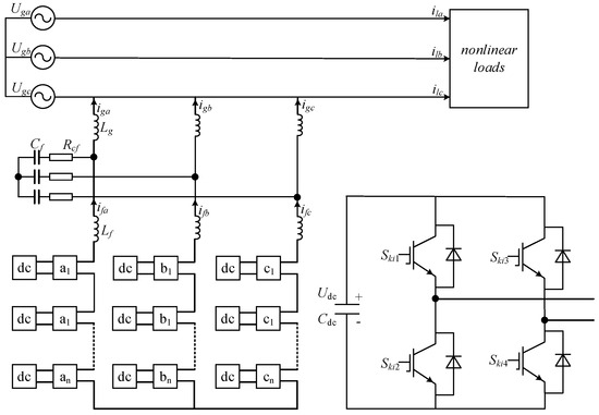
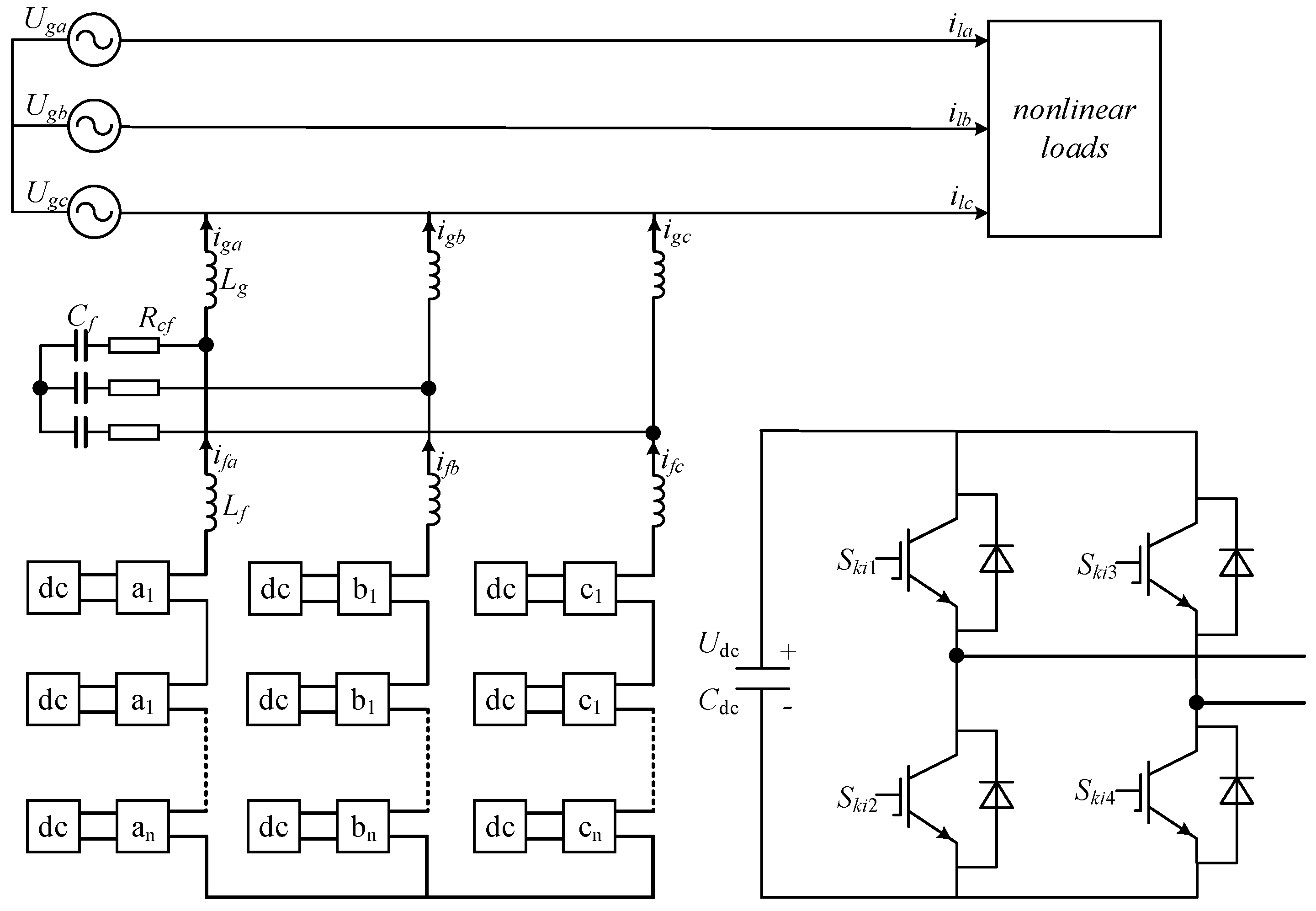
An LCL CHB STATCOM connected to the power grid is depicted in Figure 1. Here, () denotes the three-phase grid voltage, () represents the harmonic current, is the inverter-side inductance, is the grid-side inductance, is the filter capacitor, and is the damping resistor connected in series with . The () and () variables represent the three-phase inverter-side currents and grid-side currents, respectively. In addition, is the DC-link voltage, and is the split DC-link capacitor of the inverter.
Figure 1.
Topology of the cascaded H-bridge STATCOM.
Based on Figure 1, the mathematical model of the LCL CHB STATCOM in the three-phase reference frame can be derived as given in (1), where , , and denote the filter capacitor voltages of phases a, b, and c, respectively. () denotes the three-phase inverter output voltages.
Because an LCL filter inherently tends to exhibit resonance, a passive damping branch composed of and is usually added to improve system damping and suppress the resonance peak. The following assumptions are adopted: the grid is a balanced three-phase system, the filter inductors remain unsaturated, the inverter-switching devices are ideal and lossless, and the winding resistances of the inductors on both sides of the filter are neglected. The passive damping branch is retained in the detailed LCL filter model and in the MATLAB/Simulink R2021b simulation model. However, it is not explicitly included in the deadbeat current control law. Instead, the controller is designed based on the WAIC reduced equivalent first-order plant, while the damping branch remains in the plant model to reflect its influence on LCL resonance and stability. Under these assumptions, the mathematical model of the LCL filter in the synchronous reference frame can be derived from Kirchhoff’s voltage and current laws, as given in (2).
2.2. Analysis of the LCL Filter
Since the LCL filter is symmetric in the three phases, a single phase is selected for analysis.
denotes the inverter-phase output voltage. By applying Kirchhoff’s laws, the relationships between and the grid side-inductor current () and between and the inverter-side inductor current are derived as given in (3) and (4), respectively.
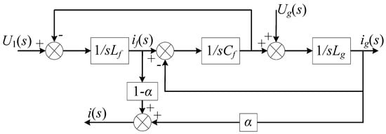
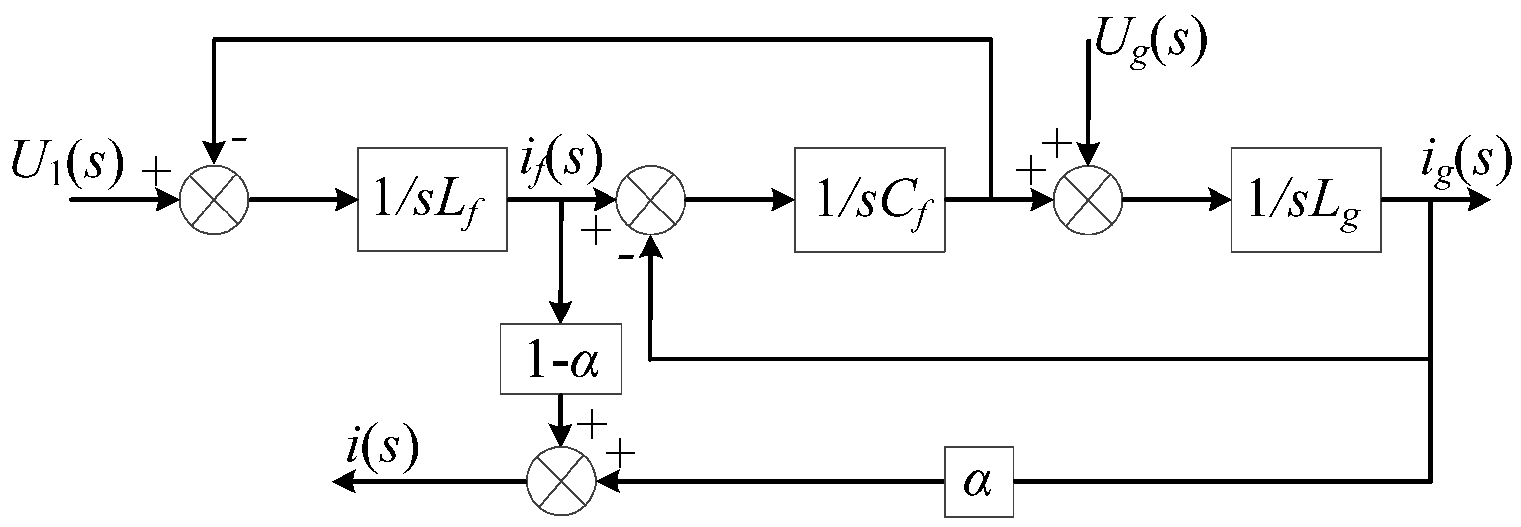
For current-loop design, the dominant low-frequency dynamics of the LCL filter can be represented by an equivalent inductive plant when the control bandwidth is set well below the LCL resonance frequency. This approximation does not imply that the capacitor branch or the resonance dynamics are physically removed; rather, the high-frequency LCL dynamics are not explicitly used in the simplified current control model. WAIC feedback is adopted to obtain a reduced-order plant for current-loop synthesis. By properly combining the inverter-side and grid-side inductor currents, WAIC reshapes the controlled current response so that the plant behaves approximately as a first-order inductive system within the intended low-frequency control bandwidth. The original LCL resonance is still present in the physical plant, but its effect on the current-loop design is reduced when the resonance is sufficiently damped and the controller bandwidth is kept below the resonance frequency [27].
The feedback block diagram of the WAIC control scheme is shown in Figure 2. Let denote the weighted actual current. By defining and the weighting coefficient as , (3) and (4) can be reformulated as (5) and (6).
Figure 2.
WAIC control scheme.
The WAIC is defined as follows:
Substituting (5) and (6) into (7), the transfer function from the inverter output voltage to the weighted current can be written as follows:
With and , the weighted combination cancels the dominant high-order terms in the current feedback path, and the low-frequency controlled plant can be approximated as follows:
Therefore, within the low-frequency range used for current-loop design, the WAIC based controlled plant can be represented by the following equivalent first-order model:
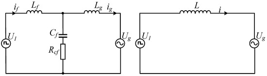
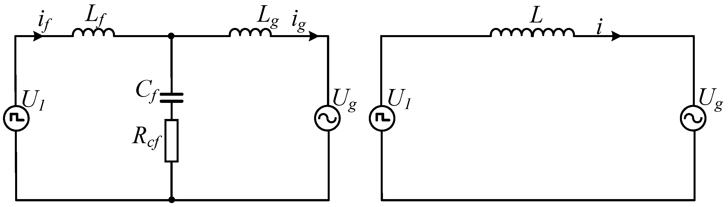
The above WAIC-based approach approximately simplifies the third-order LCL system into an equivalent first-order L-filter model, and the topology shown Figure 1 is simplified to that shown in Figure 3. It should be emphasized that this reduced-order model is a control-oriented approximation rather than an exact full-frequency representation of the LCL filter. Around the LCL resonance frequency, the third-order dynamics still exist and are affected by the passive damping branch. In this study, the approximation is used to design the DB current loop, while the complete LCL-filtered STATCOM model is retained in the simulation to evaluate resonance damping and harmonic compensation performance.
Figure 3.
Schematic diagram of the the simplified LCL filter.
For the parameters used in this study, the LCL resonance frequency can be estimated as follows:
Accordingly, the reduced-order model is targeted at the low-frequency current control region below the LCL resonance frequency, especially the fundamental and dominant low-order harmonic components. Near , the full LCL dynamics and damping branch must be considered, and the current-loop bandwidth should be set sufficiently below to avoid exciting the resonance peak.
3. Proposed FARC with DB Control Strategy
3.1. DB Controller Design
In the synchronous reference frame, a feedforward decoupling network is introduced to cancel the cross-coupling components so that the current loops can be treated as approximately first-order systems.
From the WAIC-based reduced-order model, which is used for low-frequency current-loop design, the following voltage–current relationship can be obtained:
Discretizing (12) with the sampling period () yields the following one-step prediction model:
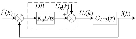
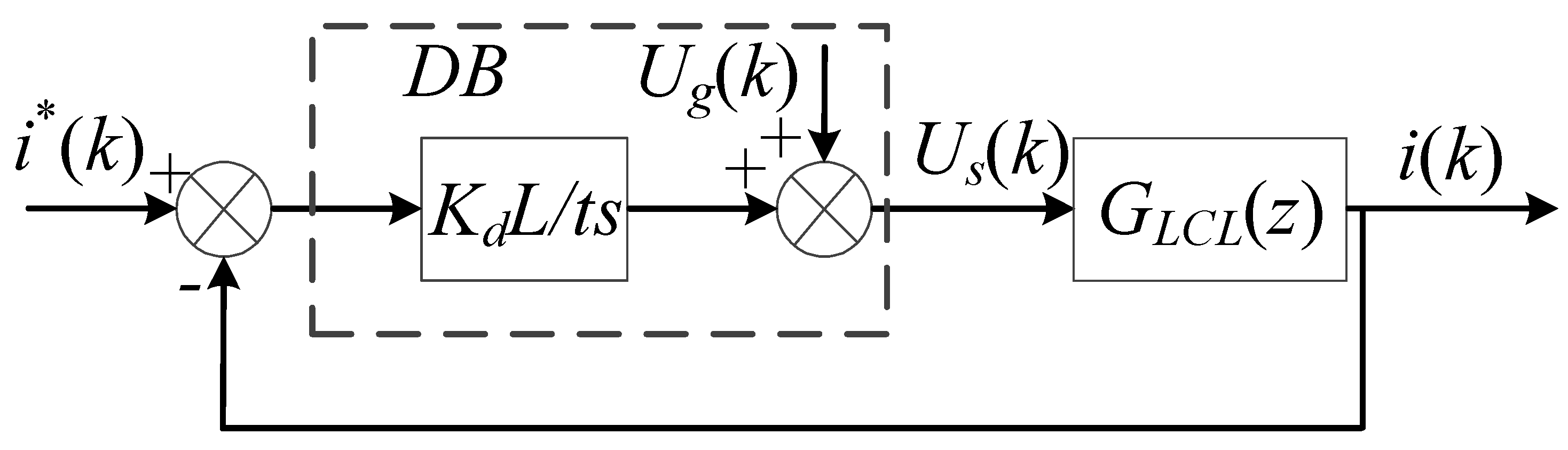
In the ideal deadbeat case, the weighted average inductor current is forced to reach the reference value in the next sampling interval, i.e., . In practical digital implementation, this equation is interpreted as a one-step predictive control law, where the voltage command calculated from the sampled current and the sampled grid-voltage feedforward term is applied in the next PWM period. Therefore, the voltage command can be written as follows:
Here, is the inverter voltage command generated by the DB current controller, and is the deadbeat gain. The normalized inverter command is defined as follows:
Here, is the normalized modulation command limited to the range of . This limitation represents the inverter voltage saturation in the PWM implementation. The normalized command () is then sent to the CPS-SPWM modulator and compared with the phase-shifted carrier signals to generate the gate pulses for each H-bridge cell.
Figure 4.
Current loop under deadbeat control.
In practical digital implementation, the DB controller is affected by sampling, computation, grid-voltage measurement, and PWM update delays. In this study, the control law is implemented in a one-step predictive form: the voltage command calculated from the sampled current and the sampled grid-voltage feedforward term () is applied in the next PWM period. Therefore, the grid-voltage measurement delay is treated as part of the sampled feedforward and digital update delay. No additional high-order delay compensator is introduced in this work. Instead, the deadbeat gain () is used to moderate the current-loop response and improve robustness against delay, parameter mismatch, and voltage saturation. The ideal choice () gives the fastest deadbeat response, whereas a smaller value reduces overshoot and oscillation when the equivalent inductance (L) deviates from its nominal value. In this study, was tuned in simulation starting from 1, then reduced until a fast but non-oscillatory current response was obtained under the tested operating conditions [28].
3.2. Conventional RC
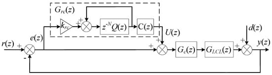
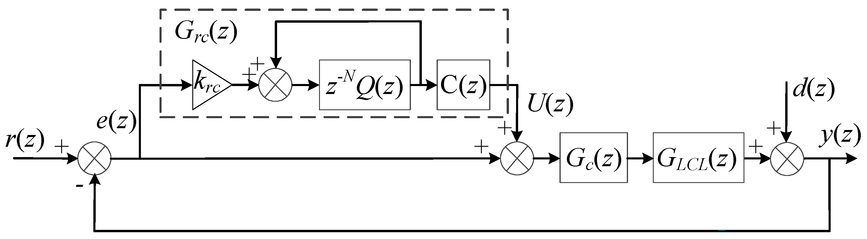
Figure 5 illustrates the closed-loop control scheme with a plug-in digital CRC. The signals and blocks are defined as follows: and denote the reference and output signals, respectively; is the tracking error; and represents an external disturbance. denotes the discrete-time model of the LCL-filtered plant, is the conventional feedback controller, and is the feedforward plug-in repetitive controller [29].
Figure 5.
Plug-in repetitive control system.
In the plug-in configuration, the CRC-based control scheme consists of a plug-in CRC controller, along with a state-feedback controller. In the discrete-time domain, the CRC can be formulated as follows:
The parameter denotes the gain of the RC, and acts as a robustness-shaping factor, implemented either as a low-pass filter or as a constant with a magnitude of less than one. In this study, a simple smoothing low-pass term () is employed. denotes the phase-led compensator used to improve the stability margin of the plug-in repetitive control loop, and denotes the output of the CRC. The same compensator notation () is used in the subsequent FARC formulation for consistency. The period length in samples is given by , where is the sampling frequency and f is the fundamental frequency of the reference () or disturbance (); thus, N is the order (memory length) of the RC. The singularities of the plug-in controller () are located at harmonic frequencies (), with , where for even values of N and for odd values of N. When , the magnitude of at these harmonic frequencies becomes arbitrarily large; therefore, according to the internal-model principle, the CRC yields zero steady-state tracking error for all harmonic components below the Nyquist frequency, provided that N is an integer.
3.3. Thiran All-Pass Filter
In the FARC implementation, the period length in samples is generally a non-integer and is denoted as [30]. It is decomposed into an integer delay part and a fractional delay part:
Here, E is the integer delay implemented by , and M is the remaining delay approximated by the Thiran all-pass filter. For an -order Thiran filter, M is further written as follows:
Here, is the filter order, and d is the fractional-delay offset. In this study, d is selected within the range of by properly choosing E so that the Thiran filter operates in its recommended delay range.
In most fractional-delay approximation schemes, IIR structures are commonly realized as all-pass filters. By definition, an all-pass filter exhibits unit magnitude over the entire frequency range, which makes it suitable for FD implementation because the design can focus on matching the desired phase delay. The z-domain transfer function of an -order all-pass filter can be expressed as follows:
For a desired delay (M), the coefficients of the -order Thiran all-pass filter are computed as follows:
Here, m is the coefficient index, and n is the product index. The binomial coefficient is defined as follows:
For the notation used in this paper, the standard delay parameter in the Thiran stability condition is M [31]. Therefore, the all-pass filter is stable when
In practical FD design, M is usually selected close to the filter order, namely
so that
The definitions of the delay-related variables used in the Thiran based FARC are summarized in Table 1.
Table 1.
Definitions of delay-related variables used in the Thiran based FARC.
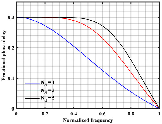
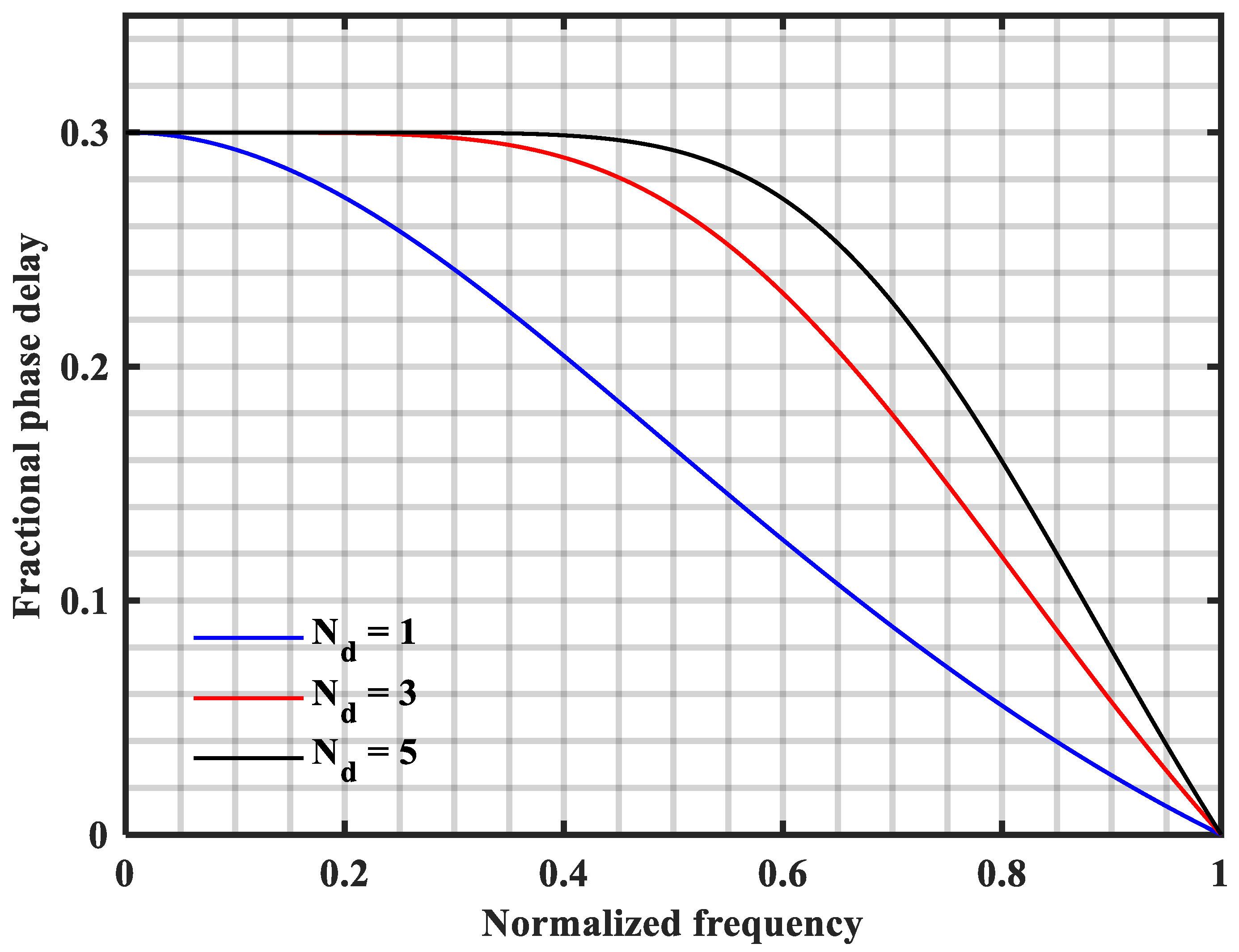
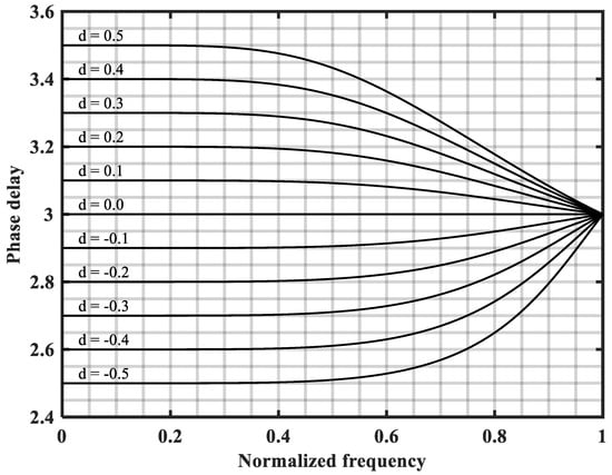
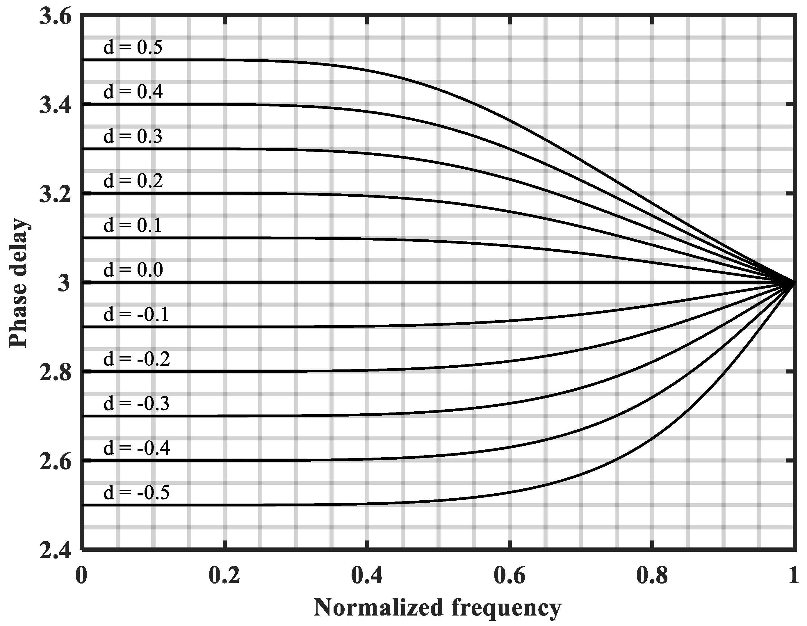
Figure 6 presents the phase-delay characteristics of first-, third-, and fifth-order Thiran all-pass filters for a fractional delay of . It can be observed that a higher filter order () broadens the frequency range over which the phase delay closely matches the desired value. Figure 7 shows the phase-delay characteristics of a third-order Thiran all-pass filter for different fractional-delay (FD) values, indicating that accurate delay approximation can be achieved in the low-frequency range. Since the filter coefficients are given by closed-form expressions, they can be updated online with low computational effort, enabling rapid FD tuning. Therefore, the Thiran all-pass filter is suitable for FD implementation. In practice, the approximation bandwidth and filter order () should be selected by balancing harmonic compensation requirements and computational complexity.
Figure 6.
Fractional phase-delay curves of first-, third-, and fifth-order Thiran all-pass filters corresponding to an FD value close to .
Figure 7.
Phase-delay characteristics of a third-order Thiran all-pass filter for various fractional-delay values (d).
In this study, a third-order Thiran all-pass filter is adopted in the subsequent simulations as a compromise between delay approximation accuracy and computational burden. For the present STATCOM case, and ; hence, even the 25th harmonic corresponds to a frequency normalized by the sampling frequency of only , which is still in the low-frequency approximation region. As shown in Figure 6 and Figure 7, the third-order filter provides a sufficiently flat phase-delay response in this region, while a fifth-order filter mainly increases the recursive order and coefficient calculations. Therefore, is selected in this work.
3.4. Thiran All-Pass Filter FARC
In practical power systems, the grid frequency (f) typically varies within a certain range. Consequently, for a fixed sampling rate (), the corresponding RC order () is generally a non-integer, and the ideal fractional sample delay () cannot be implemented exactly. Even if N is rounded to the nearest integer, a conventional CRC cannot precisely track fractional period signals because the resonance peaks of its internal model no longer coincide with the actual harmonic frequencies. In other words, a digital CRC operating at a fixed sampling rate () is unable to accurately compensate for periodic signals whose fundamental frequency drifts over time. As a result, the harmonic suppression capability of the repetitive controller is significantly reduced, and its tracking accuracy deteriorates noticeably. Using Euler’s identity, the magnitude of the RC transfer function in (16), neglecting the influence of the low-pass filter , can be written as follows:
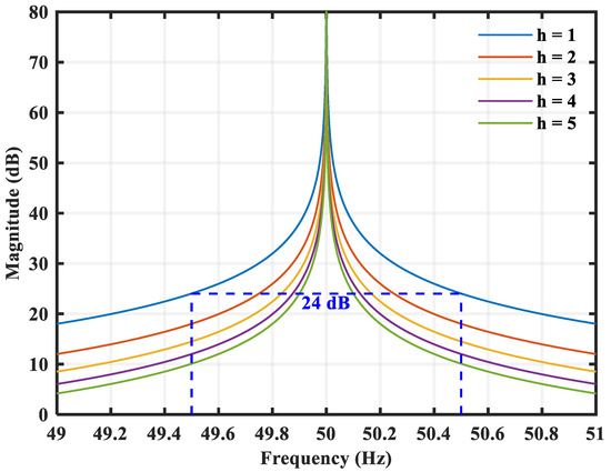
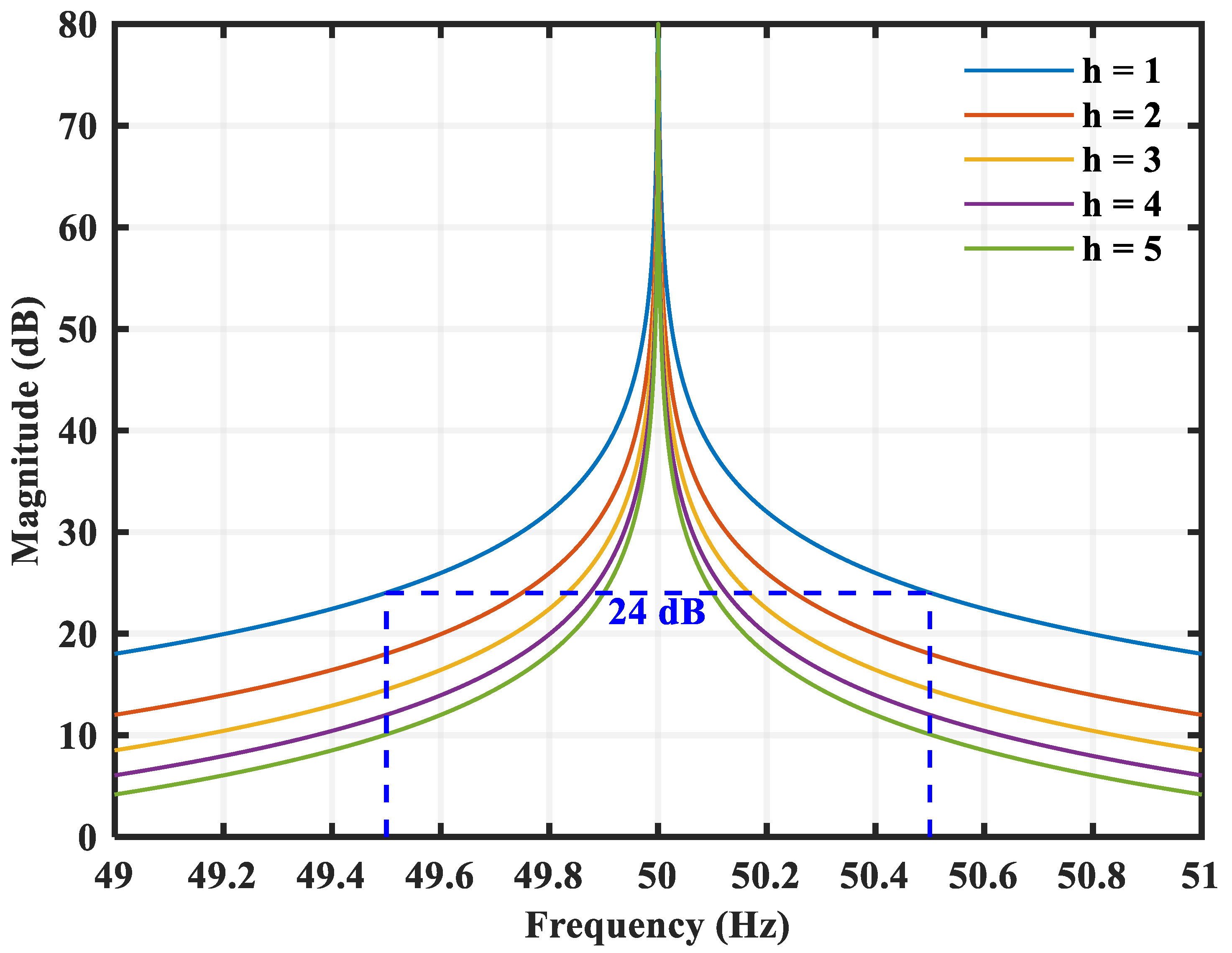
Figure 8 illustrates the magnitude characteristics of the conventional RC around the first five harmonic orders when it is tuned to a fundamental. When the reference frequency is shifted by from its nominal value, the gain at the fundamental harmonic, which is ideally infinite at the tuning frequency, collapses to approximately , and the reduction becomes even more pronounced for higher-order harmonics. Consequently, even a small mismatch between the actual and nominal reference frequency leads to a marked deterioration in the periodic signal tracking and harmonic suppression performance of the CRC.
Figure 8.
Sensitivity of the RC magnitude response to reference-frequency deviations.
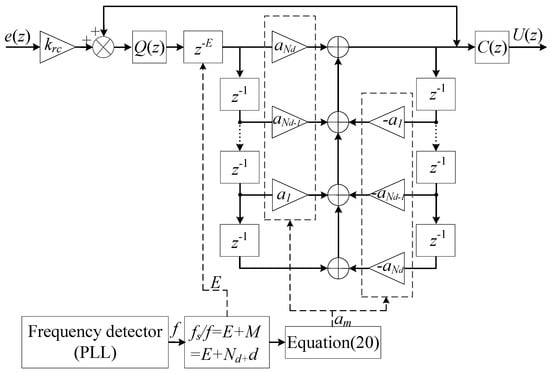
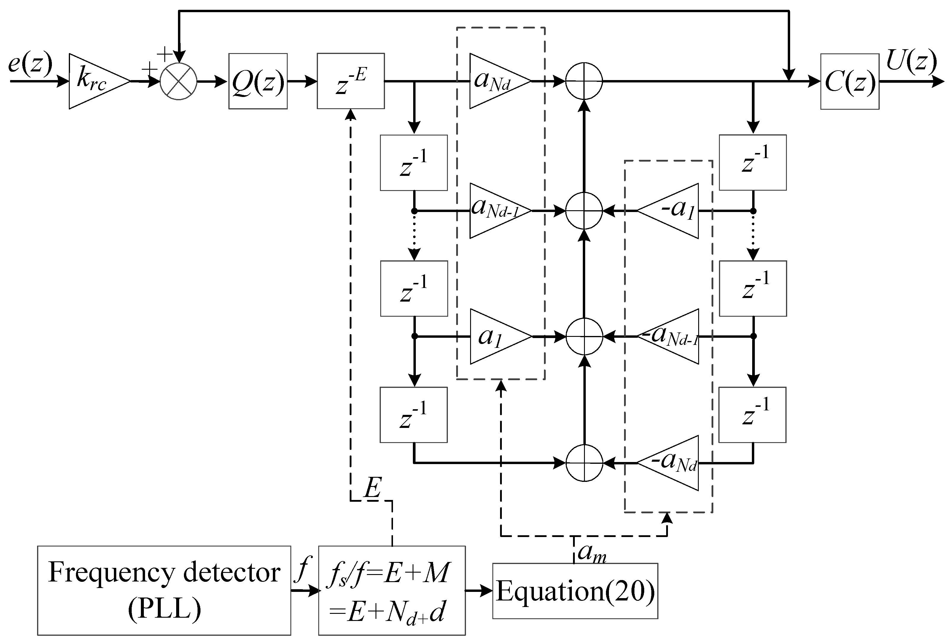
By incorporating the Thiran all-pass filter, the CRC scheme is upgraded to a FARC scheme with improved frequency adaptability [32]. The period length () is decomposed as , where E is the integer delay implemented by and M is the remaining delay approximated by the Thiran all-pass filter. According to the Thiran all-pass approximation described in Section 3.3, the fractional-delay term can be approximated as .
By replacing the integer delay () in the CRC controller with the frequency-adaptive delay (), the resulting FARC controller can be expressed as follows:
For the plug-in FARC structure, the closed-loop stability must be checked because the repetitive internal model may introduce very high gain around the harmonic frequencies. Let denote the discrete-time plant seen by the plug-in repetitive compensator, including the WAIC-based reduced plant and the DB inner-current loop. The baseline DB-current loop is first required to be internally stable without the repetitive branch. Under this condition, the plug-in FARC loop can be analyzed by the small-gain theorem by defining the following:
A sufficient stability condition for the plug-in FARC system is
Because the Thiran filter () is an all-pass filter and the integer delay () has unit magnitude, the above condition can be simplified as follows:
Therefore, , , and should be selected such that the magnitude of the regeneration term remains below unity over the frequency range of interest. In this study, the smoothing filter () is used to attenuate high-frequency gain, while the phase-led compensator () is introduced to compensate for the phase lag of . The RC gain () is then tuned conservatively to obtain harmonic compensation without violating the above stability condition.
It is worth noting that the CRC controller in (16) is obtained as a particular case of the FARC controller by setting . The FARC controller provides a unified framework for tracking or rejecting periodic signals with an arbitrary fundamental frequency. Its block diagram is illustrated in Figure 9. Using the relation expressed as , the integer delay E can be selected such that the fractional delay offset (d) lies within . For example, when and , . With and , one obtains and . When , . With and , one obtains and . In both cases, , , and are satisfied.
Figure 9.
Block diagram of the proposed FARC.
3.5. FARC of CHB STATCOM
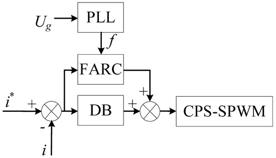
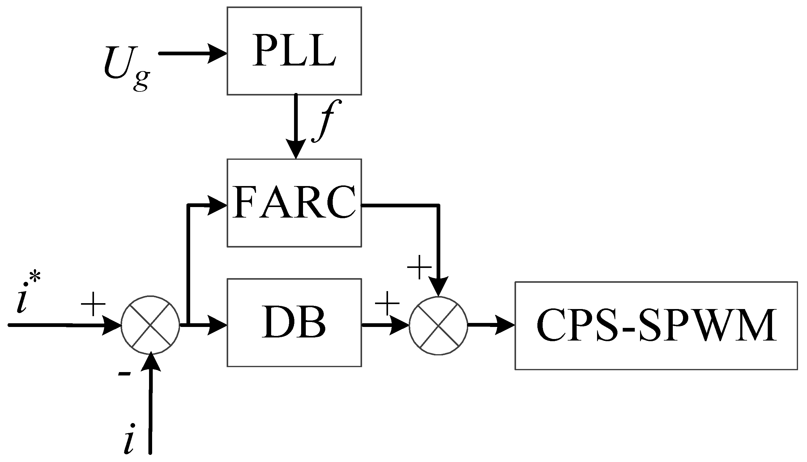
This paper exploits the complementary performance of the FARC and the DB controller. The DB controller ensures rapid dynamic response, whereas the FARC is employed to eliminate residual periodic tracking errors, thereby maintaining accurate current control under fluctuating grid and reference frequencies.This division of functions distinguishes the proposed structure from studies that use WAIC-based DB control alone or fractional-delay RC alone because the former cannot provide frequency-adaptive harmonic internal model compensation, whereas the latter usually does not address the LCL order reduction and fast inner-current transient response required by CHB STATCOM applications.
The schematic of the internal current control structure for the LCL CHB STATCOM is presented in Figure 10, employing a Frequency-Adaptive Repetitive Controller (FARC) and a Deadbeat (DB) controller in a parallel configuration. For frequency adaptation, the grid frequency is estimated by a synchronous reference-frame PLL, then supplied to the FARC module. The estimated frequency is updated at each digital control sampling instant. In the present implementation, the adaptation is performed in discrete time: the period length (), the integer delay (E), the residual delay (M), and the fractional-delay offset (d) are recalculated according to the updated frequency estimate, and the Thiran all-pass coefficients are then updated using the coefficient formula given in Section 3.3. No threshold-triggered coefficient update is used in the simulation. The frequency estimate is filtered by the closed-loop dynamics of the PLL, so the coefficient update follows the slowly varying grid-frequency component rather than instantaneous voltage ripple. Since the grid-frequency deviations considered in this study are much slower than the control sampling frequency, this discrete time update mechanism is sufficient for the proposed frequency-adaptive repetitive controller. Furthermore, the Carrier Phase Shift Sinusoidal Pulse Width Modulation (CPS-SPWM) technique is adopted.
Figure 10.
Control scheme for the STATCOM inner-current loop.
3.6. Computational Burden and Digital Implementation
The proposed DB+FARC scheme is suitable for digital implementation because its additional computational burden mainly comes from the low-order Thiran all-pass fractional delay filter and the online update of its coefficients. Compared with the CRC scheme, the memory length of the repetitive controller is still mainly determined by the fundamental period (). The proposed method only replaces the fixed integer delay () with the frequency-adaptive delay (, where is a low-order Thiran all-pass filter). Therefore, the memory requirement remains close to that of CRC, with only a few additional delay states introduced by the Thiran filter.
In this study, a third-order Thiran all-pass filter is adopted. Its recursive IIR structure requires only a limited number of multiplications and additions at each sampling instant. The filter coefficients are calculated from closed-form expressions and updated according to the grid frequency estimated by the PLL. Since the grid-frequency variation is much slower than the control sampling frequency, the coefficient update does not impose a heavy real-time computational burden. In practical digital implementation, the coefficient update can be performed at the control sampling rate or at a lower PLL update rate, depending on the processor capability and the frequency estimation bandwidth. For one controlled current channel, the third-order Thiran all-pass filter only introduces three recursive delay states and requires a small number of multiplications and additions at each sampling instant. The repetitive control memory length is approximately , which is about 400 samples under and . In the proposed FARC, this memory is changed to an integer delay (E) plus the low-order Thiran states, so the total memory requirement remains almost the same as that of CRC. Therefore, the additional processor burden introduced by the proposed frequency-adaptive delay is limited, and the algorithm is feasible for real-time digital implementation from the viewpoint of computational complexity.
The DB controller also has a simple implementation form. It only uses the sampled current, the current reference, the equivalent inductance, and the grid-voltage feedforward term to calculate the inverter voltage command. The normalized voltage command is then sent to the CPS-SPWM module to generate gate signals for the CHB cells. Therefore, the proposed control scheme mainly consists of a one-step DB prediction, a plug-in repetitive control memory loop, a low-order Thiran all-pass filter, and a PLL-based frequency update. These operations do not require variable sampling, complicated data reindexing, or high-order fractional-delay filtering. Therefore, from the viewpoint of algorithmic complexity, the proposed scheme has moderate implementation requirements and is suitable for further hardware in the loop or experimental validation in future work.
4. Simulation Verification
To evaluate the proposed control strategy, a 10 kV LCL CHB STATCOM model is built in MATLAB/Simulink 2021b. The main system parameters are listed in Table 2. The sampling frequency is fixed at 20 kHz, while the grid frequency is set to three representative values of 50 Hz and 50 ± 0.4 Hz, corresponding to period lengths of , , and samples per cycle, respectively. This configuration allows a fair comparison between CRC and the proposed FARC under realistic frequency deviations.
Table 2.
Simulation parameters of the STATCOM system.
In the present simulation model, the CHB submodules are represented by identical H-bridge cells, and the DC-link voltages are assumed to remain balanced. The THD values reported in this paper are obtained from the grid-side current using FFT analysis in MATLAB/Simulink. The FFT window is selected after the transient response has settled and contains an integer number of fundamental cycles to reduce spectral leakage. The power factor is calculated from the grid-side active power and apparent power.The supplementary simulation and implementation settings are summarized in Table 3.
Table 3.
Supplementary simulation and implementation settings.
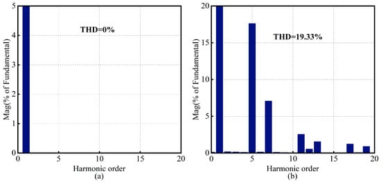
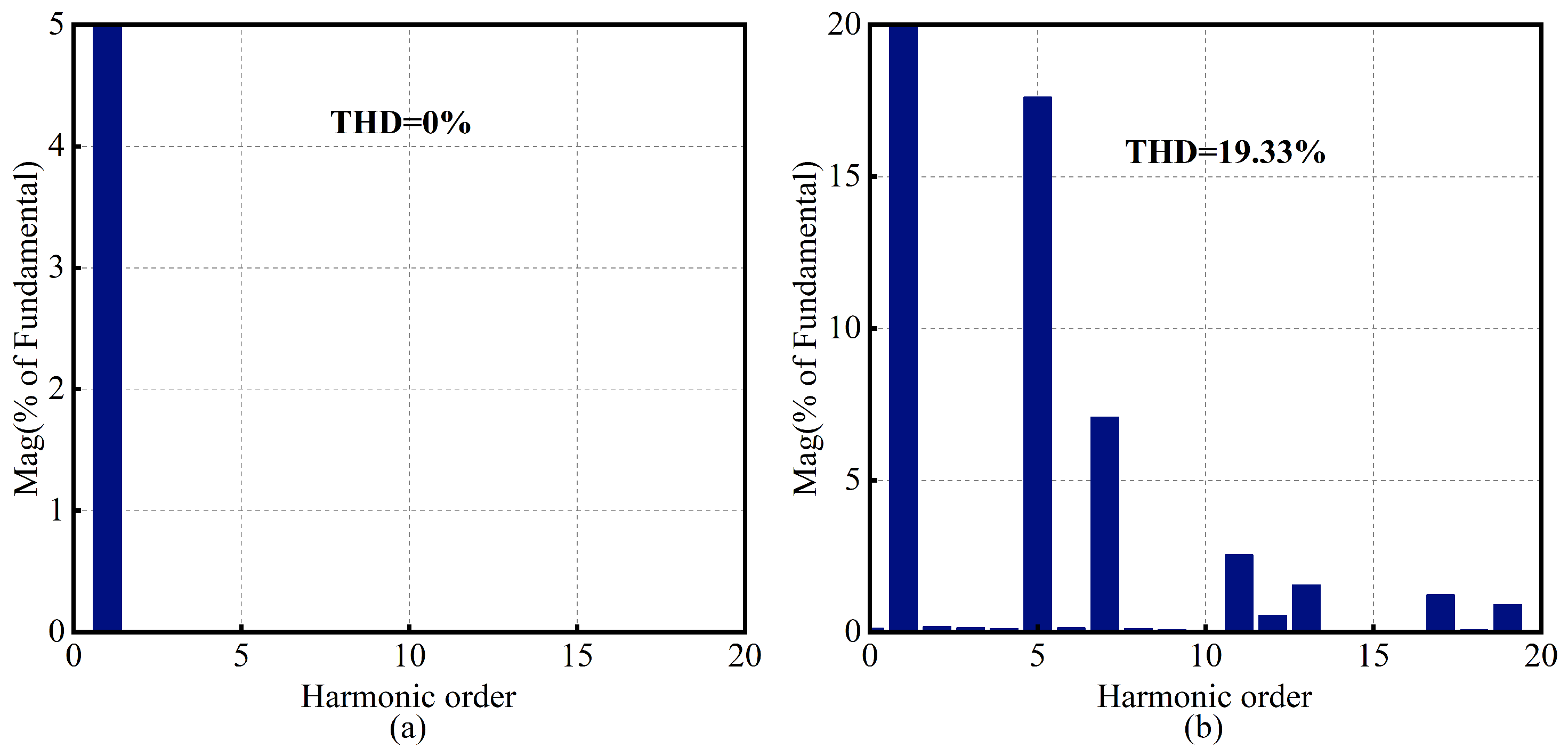
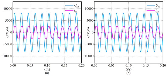
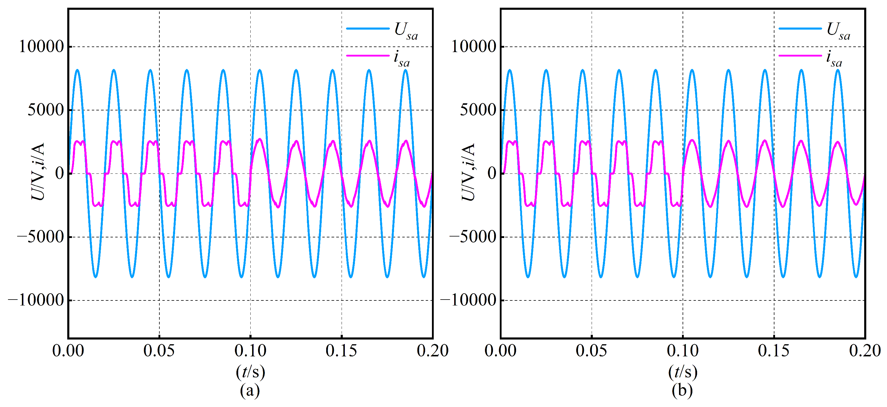
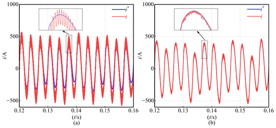
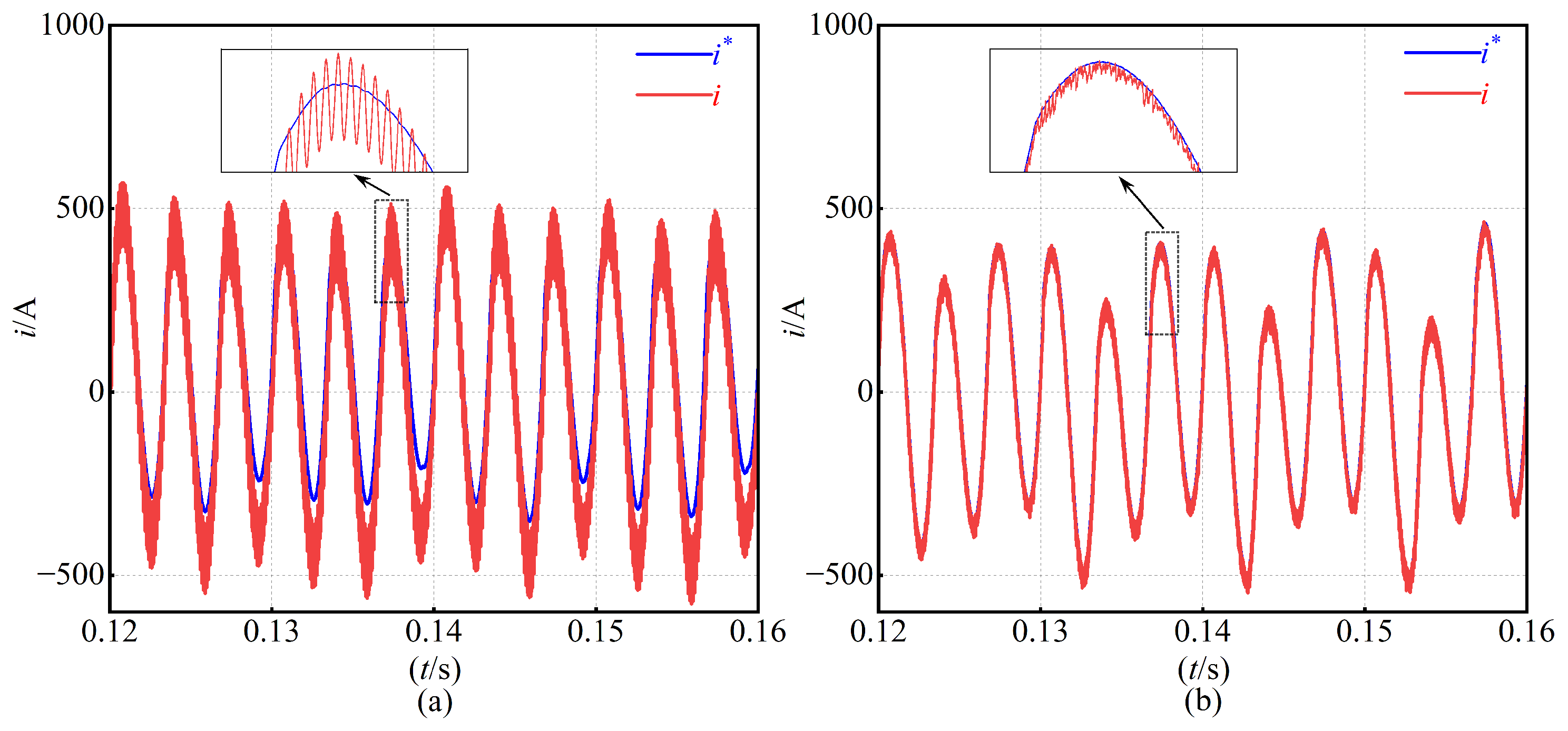
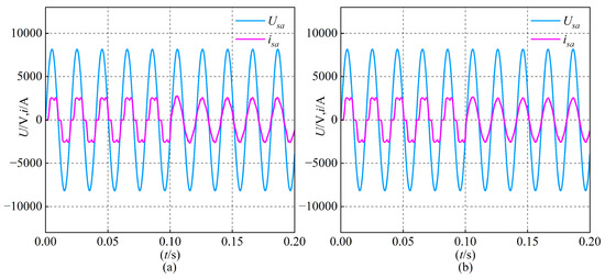
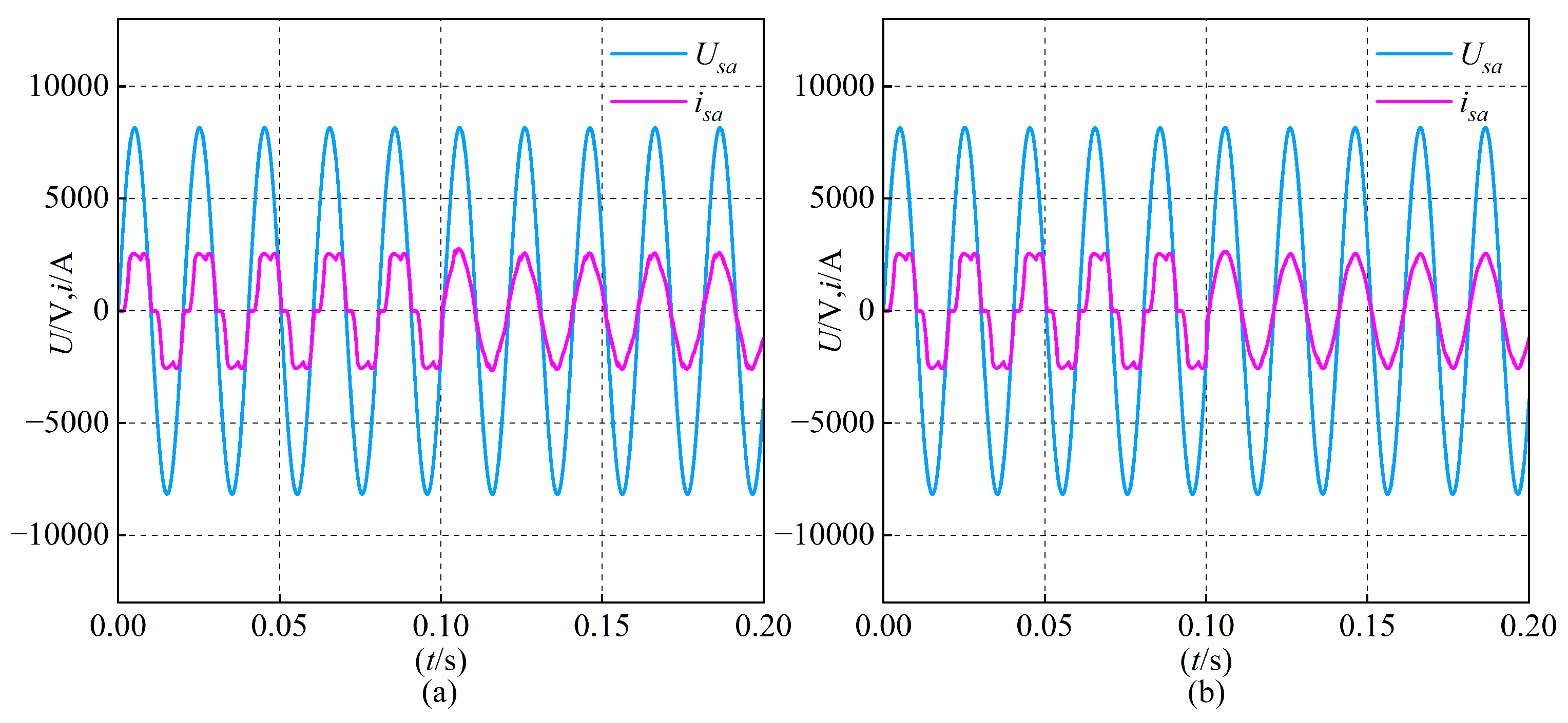
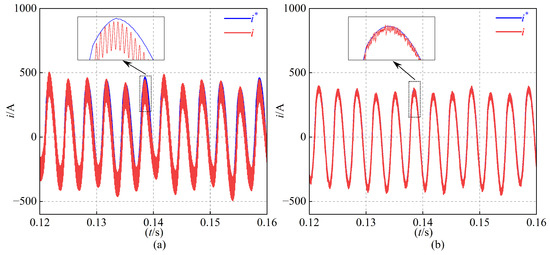
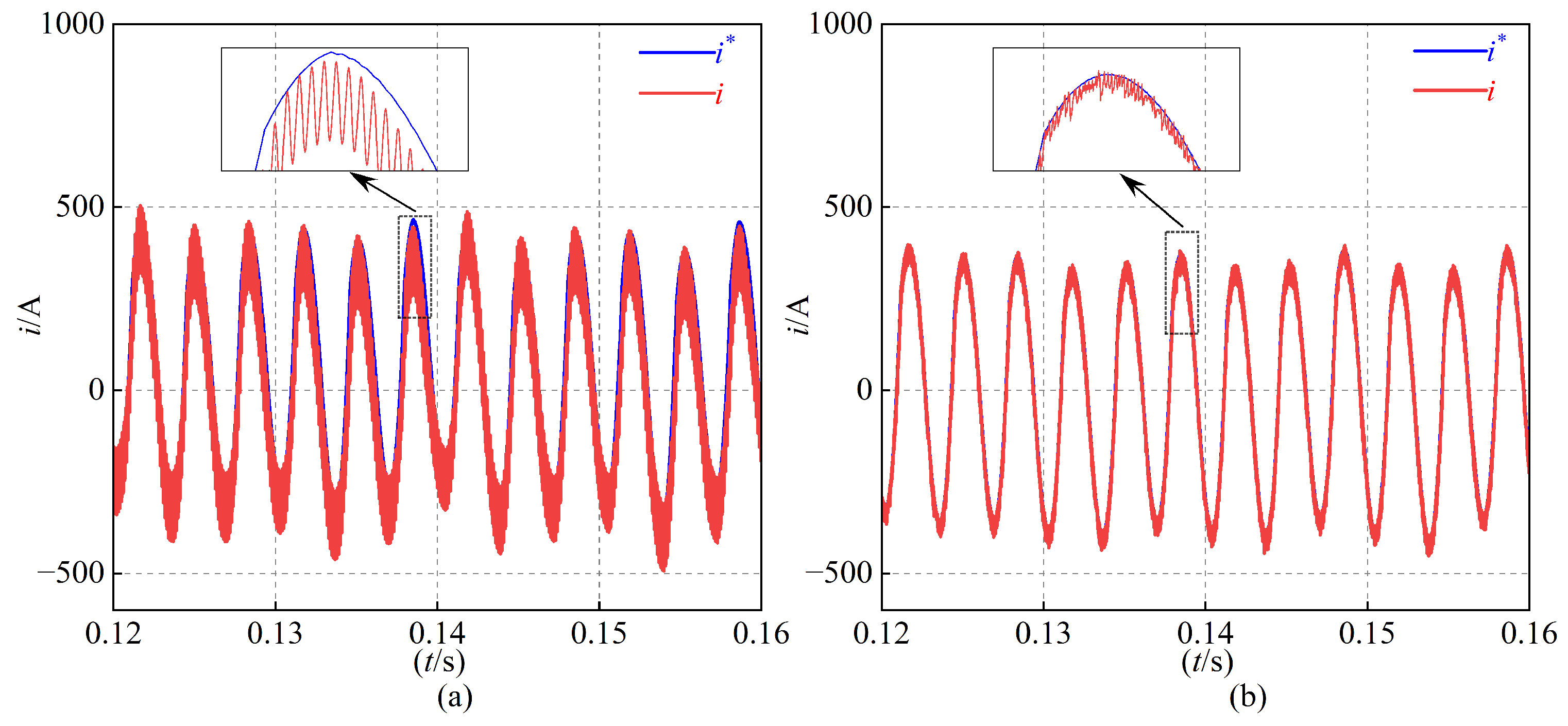
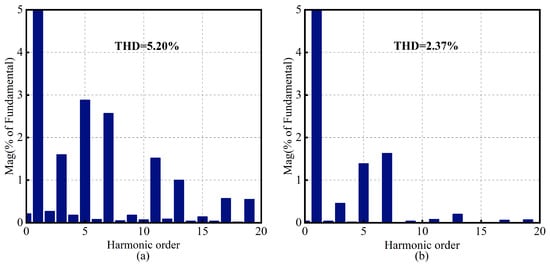
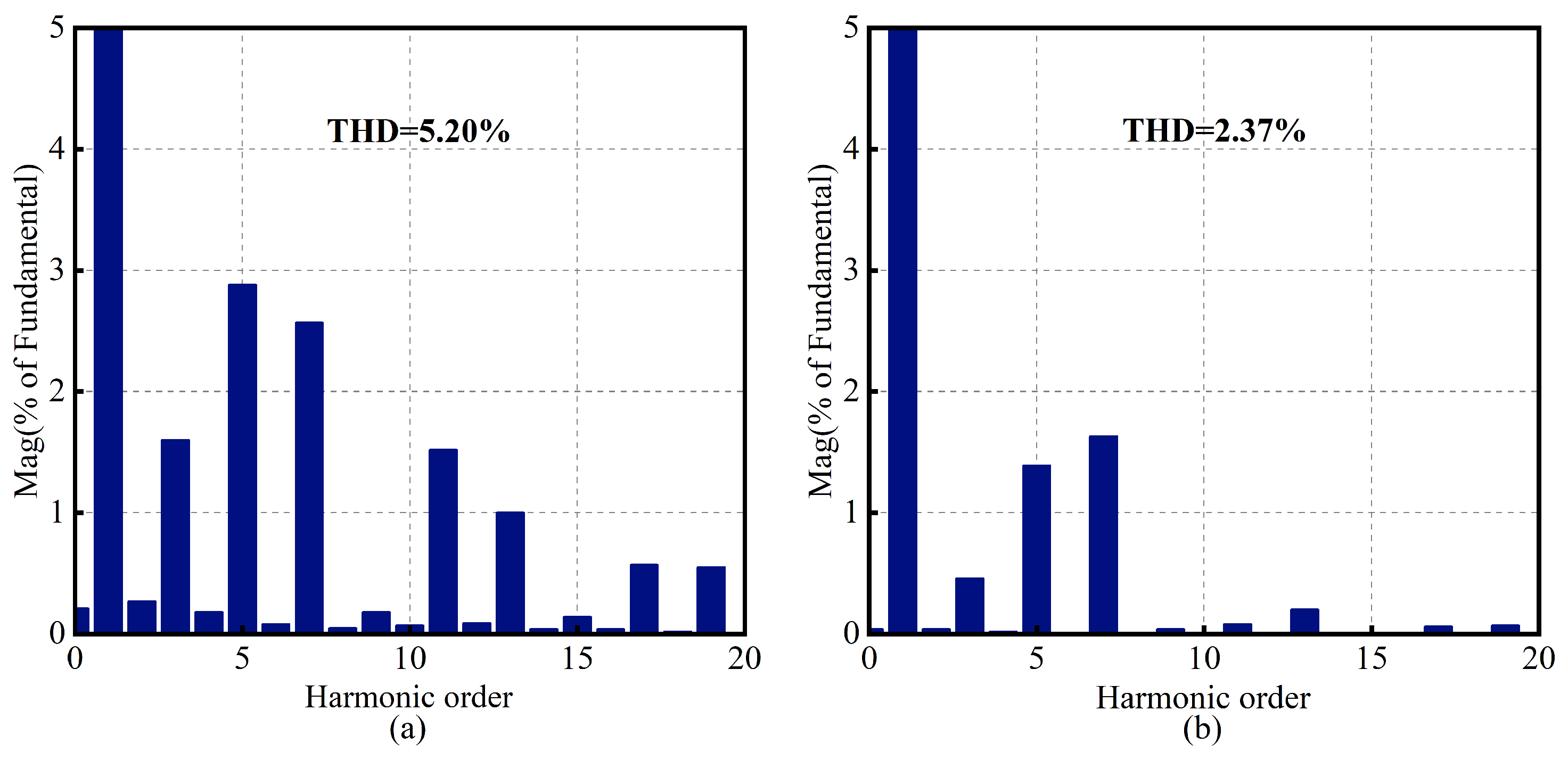
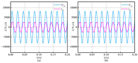
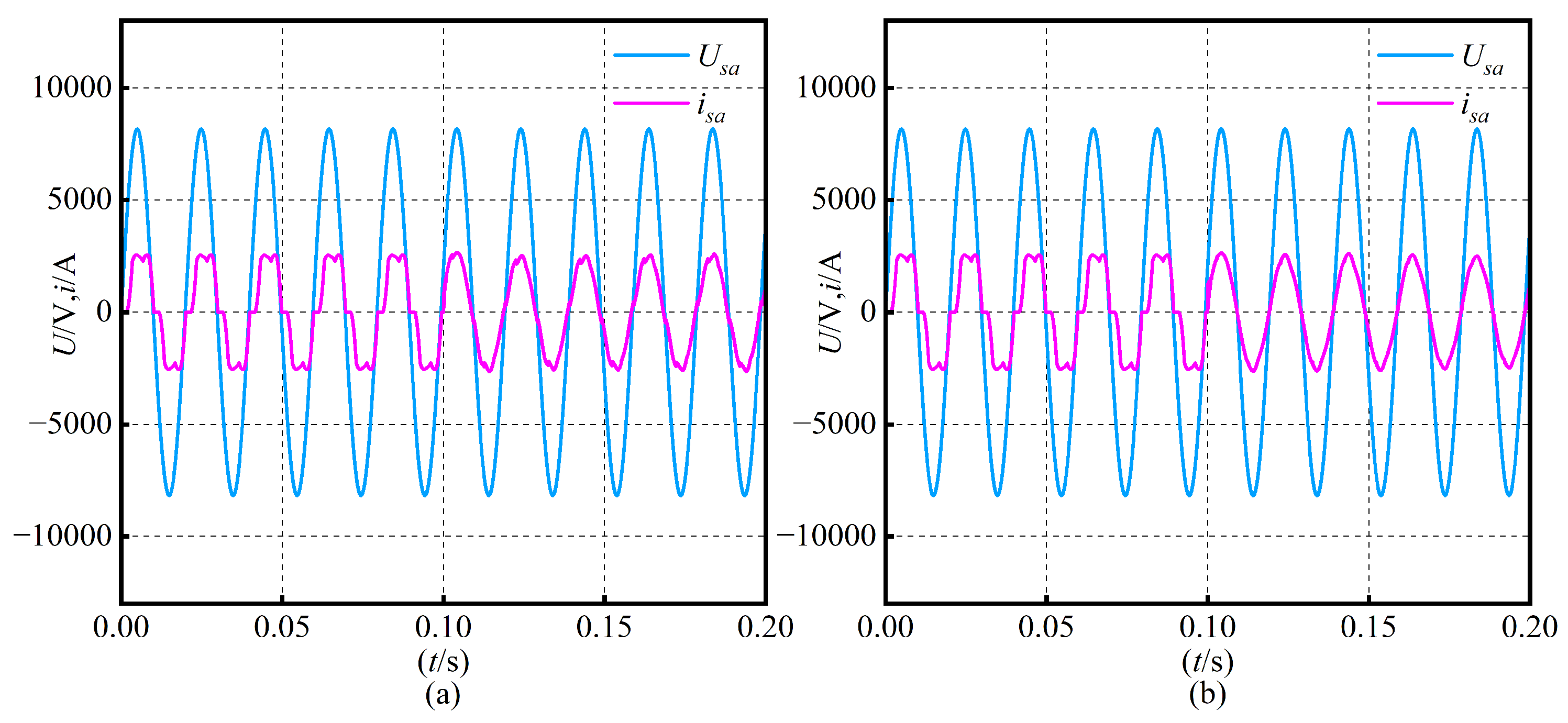
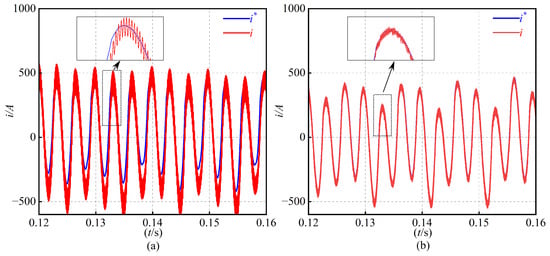
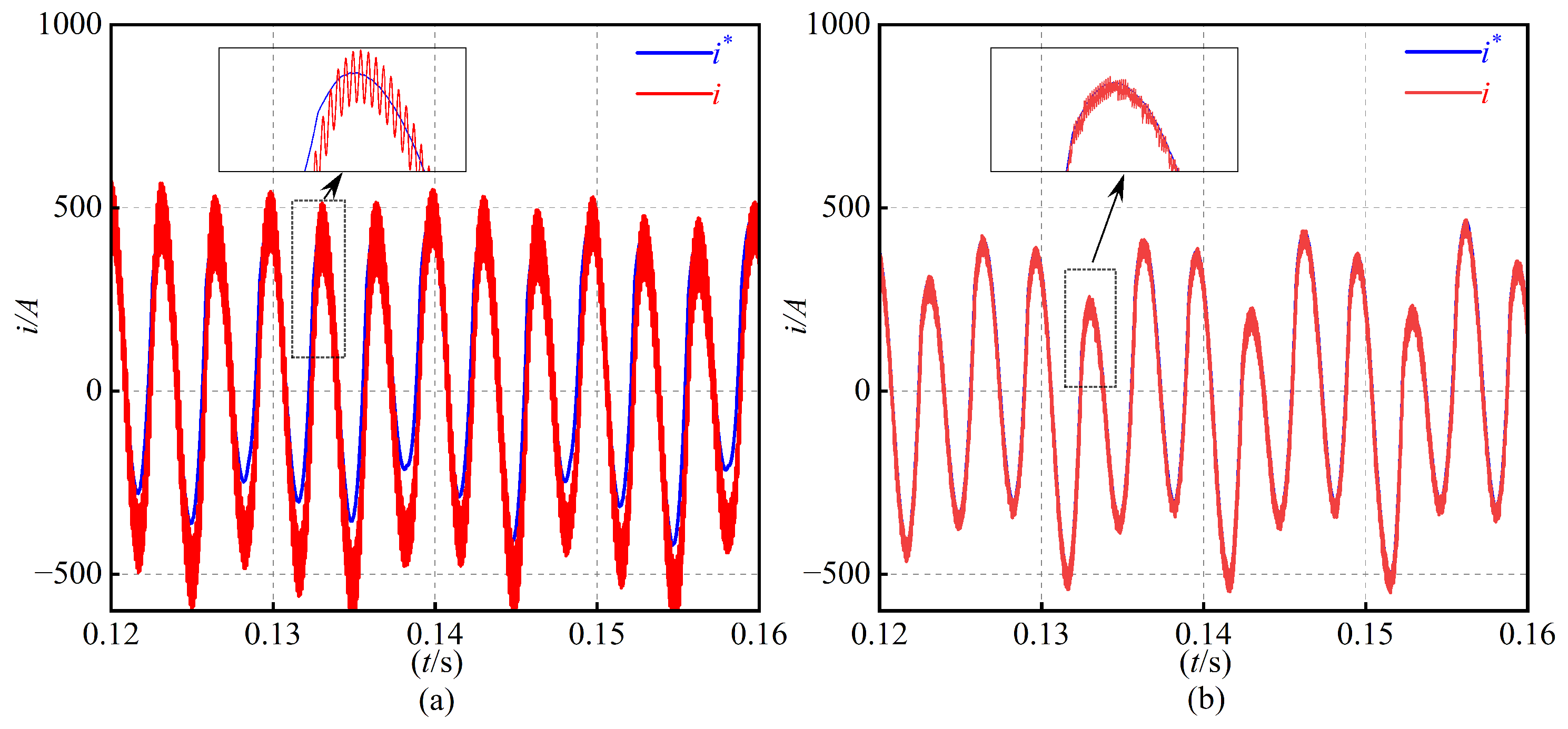
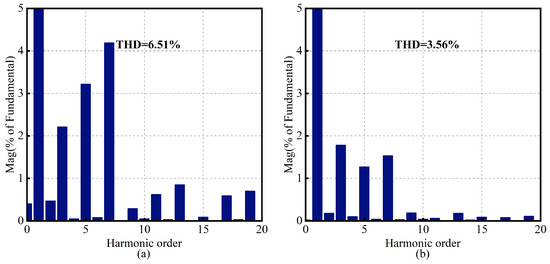
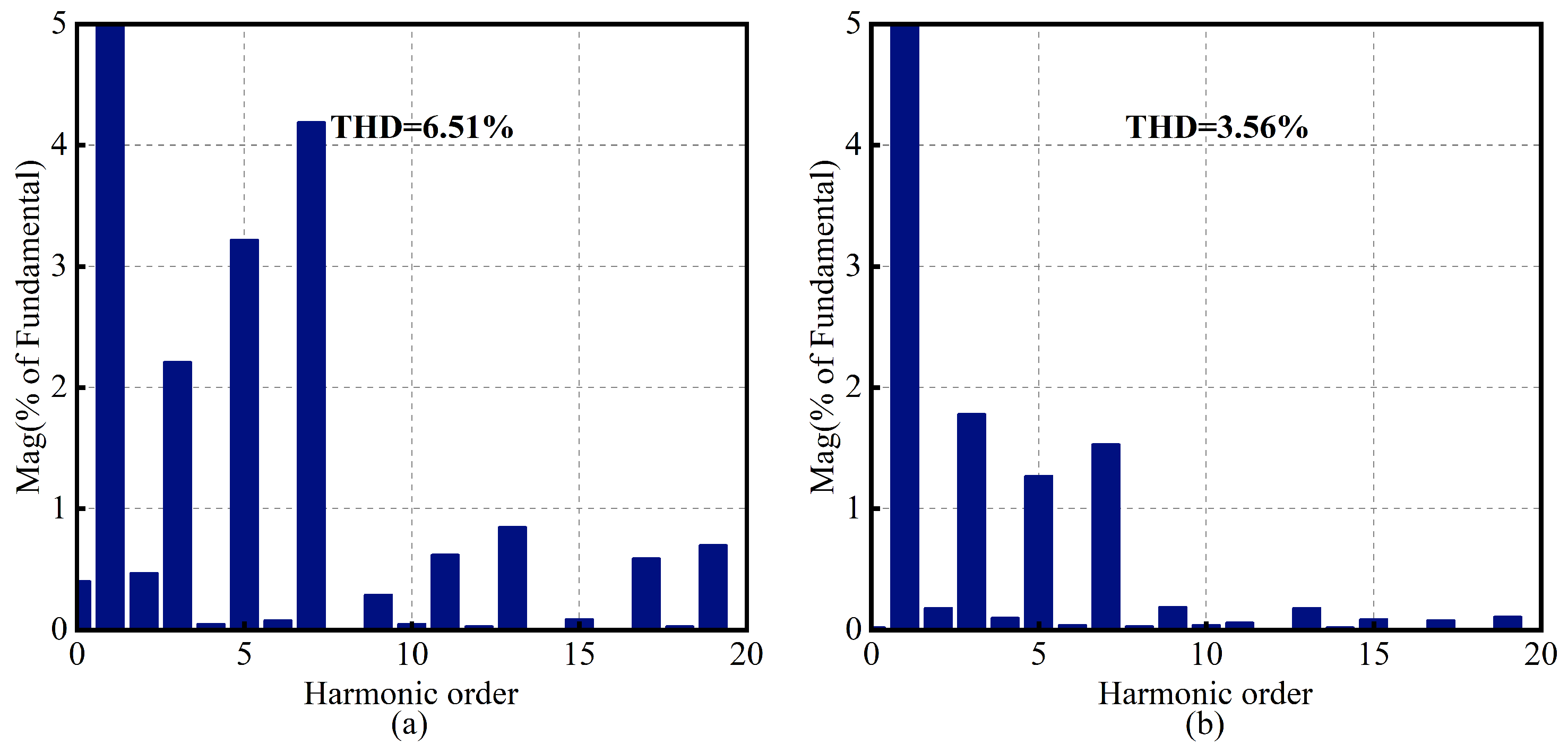
Under identical system parameters, CRC and FARC are adopted as benchmark controllers for comparison. The STATCOM is enabled at s and operates with a nonlinear load, while phase-A voltage and current waveforms are used for illustration. Figure 11, Figure 12, Figure 13, Figure 14, Figure 15, Figure 16, Figure 17, Figure 18, Figure 19 and Figure 20 summarize the steady-state results at grid frequencies of 50 Hz, 49.6 Hz, and 50.4 Hz. In all cases, the FARC-controlled compensating current exhibits a cleaner sinusoidal waveform and tracks the reference current more accurately than the CRC counterpart, whose tracking error and oscillations increase noticeably under frequency deviations.
Figure 11.
Harmonic spectrum analysis of grid voltage and current with the STATCOM inactive. (a) Grid voltage. (b) Grid current.
Figure 12.
Comparative analysis of steady-state grid voltage and grid current at 50 Hz for the LCL CHB STATCOM under CRC and FARC control. (a) CRC. (b) FARC.
Figure 13.
Comparative analysis of the compensation current and reference current at 50 Hz for the LCL CHB STATCOM under CRC and FARC control. (a) CRC. (b) FARC.
Figure 14.
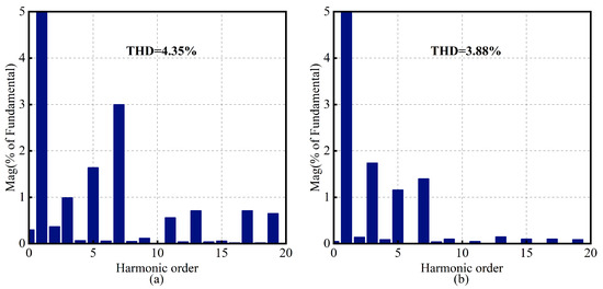
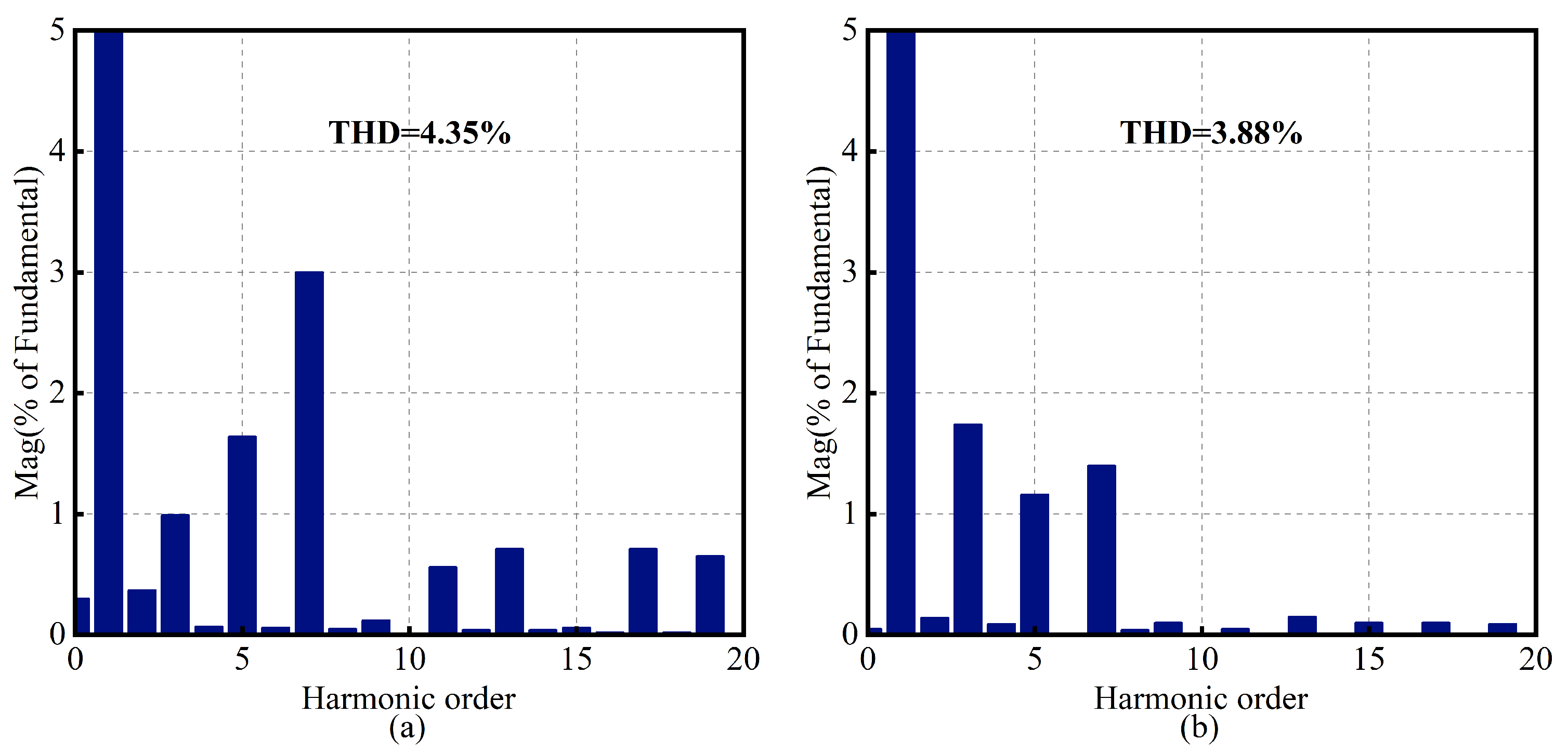
Comparative analysis of the harmonic spectrum of grid current at 50 Hz for the LCL CHB STATCOM under CRC and FARC control. (a) CRC. (b) FARC.
Figure 15.
Comparative analysis of the steady-state grid voltage and current at 49.6 Hz for the LCL CHB STATCOM under CRC and FARC control. (a) CRC. (b) FARC.
Figure 16.
Comparative analysis of the compensation current and reference current at 49.6 Hz for the LCL CHB STATCOM under CRC and FARC control. (a) CRC. (b) FARC.
Figure 17.
Comparative analysis of the harmonic spectrum of grid current at 49.6 Hz for the LCL CHB STATCOM under CRC and FARC control. (a) CRC. (b) FARC.
Figure 18.
Comparative analysis of the steady-state grid voltage and current at 50.4 Hz for the LCL CHB STATCOM under CRC and FARC control. (a) CRC. (b) FARC.
Figure 19.
Comparative analysis of the compensation current and reference current at 50.4 Hz for the LCL CHB STATCOM under CRC and FARC control. (a) CRC. (b) FARC.
Figure 20.
Comparative analysis of the harmonic spectrum of grid current at 50.4 Hz for the LCL CHB STATCOM under CRC and FARC control. (a) CRC. (b) FARC.
The corresponding harmonic spectra of the grid current confirm this behavior. Under the nominal 50 Hz condition, the grid-current THD is reduced from 4.35% with CRC to 3.88% with FARC. When the frequency decreases to 49.6 Hz, the THD under CRC rises to 5.20%, whereas FARC still limits it to 2.37%. For the 50.4 Hz case, CRC yields a THD of 6.51%, compared with 3.56% for FARC. These results demonstrate that the proposed FARC maintains superior harmonic suppression capability and current-tracking accuracy over the tested frequency range, while CRC suffers a pronounced performance degradation once the grid frequency departs from 50 Hz.
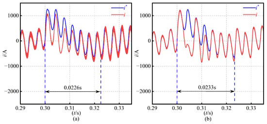
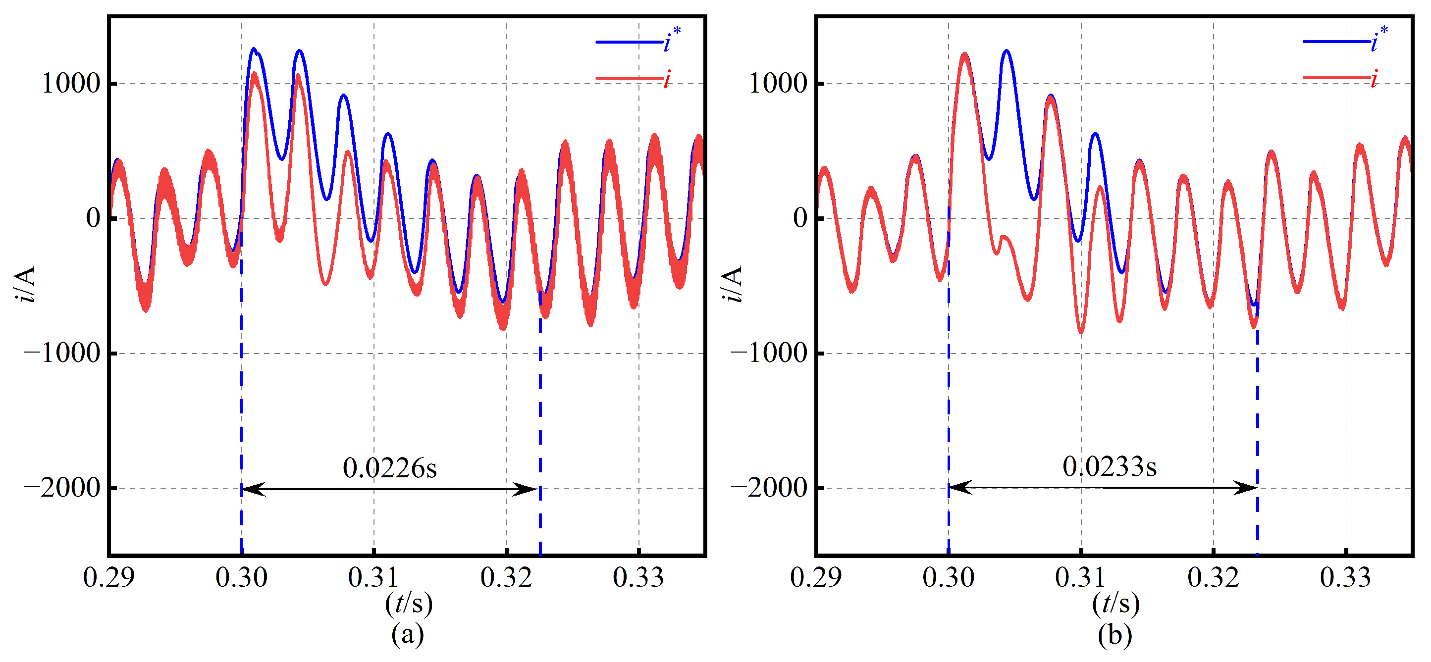
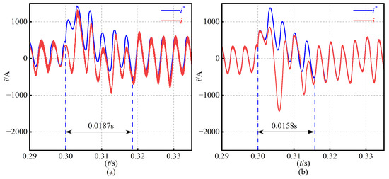
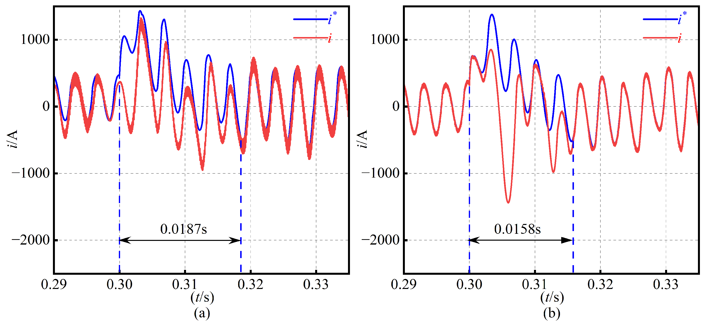
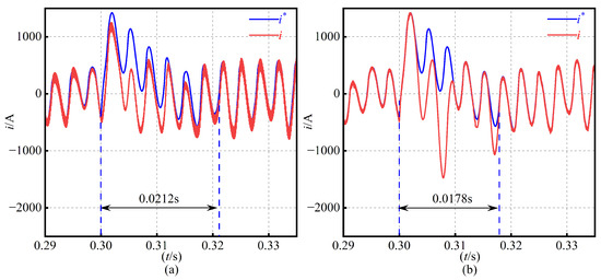
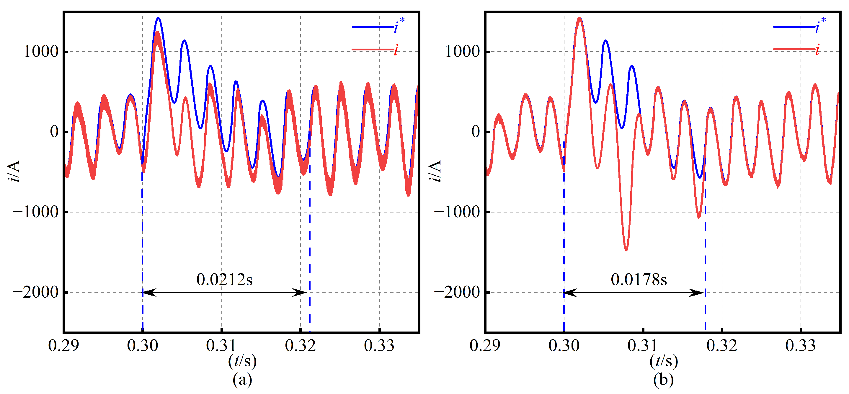
To evaluate the dynamic performance, a harmonic load step is applied at while the STATCOM remains in operation. Figure 21, Figure 22 and Figure 23 compare the compensating current and its reference at 50 Hz, 49.6 Hz, and 50.4 Hz. To improve readability, the dynamic response plots are enlarged and annotated with the recovery time after load switching. At the nominal frequency of 50 Hz, CRC and FARC exhibit comparable recovery times of 0.0226 s and 0.0233 s, respectively. Under off-nominal frequencies, the benefit of the proposed FARC becomes more evident. At 49.6 Hz, the recovery time is reduced from 0.0187 s with CRC to 0.0158 s with FARC, corresponding to a reduction of approximately 15.5%. At 50.4 Hz, it is reduced from 0.0212 s to 0.0178 s, corresponding to a reduction of approximately 16.0%. After the transient, the FARC scheme also produces a compensating current with lower visible harmonic distortion, indicating improved disturbance rejection capability during harmonic load switching.The corresponding dynamic recovery times are summarized in Table 4.
Figure 21.
Dynamic response comparison of compensating current and reference current during harmonic load switching at 50 Hz. (a) CRC. (b) FARC.
Figure 22.
Dynamic response comparison of compensating current and reference current during harmonic load switching at 49.6 Hz. (a) CRC. (b) FARC.
Figure 23.
Dynamic response comparison of compensating current and reference current during harmonic load switching at 50.4 Hz. (a) CRC. (b) FARC.
Table 4.
Dynamic recovery time during harmonic load switching.
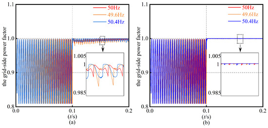
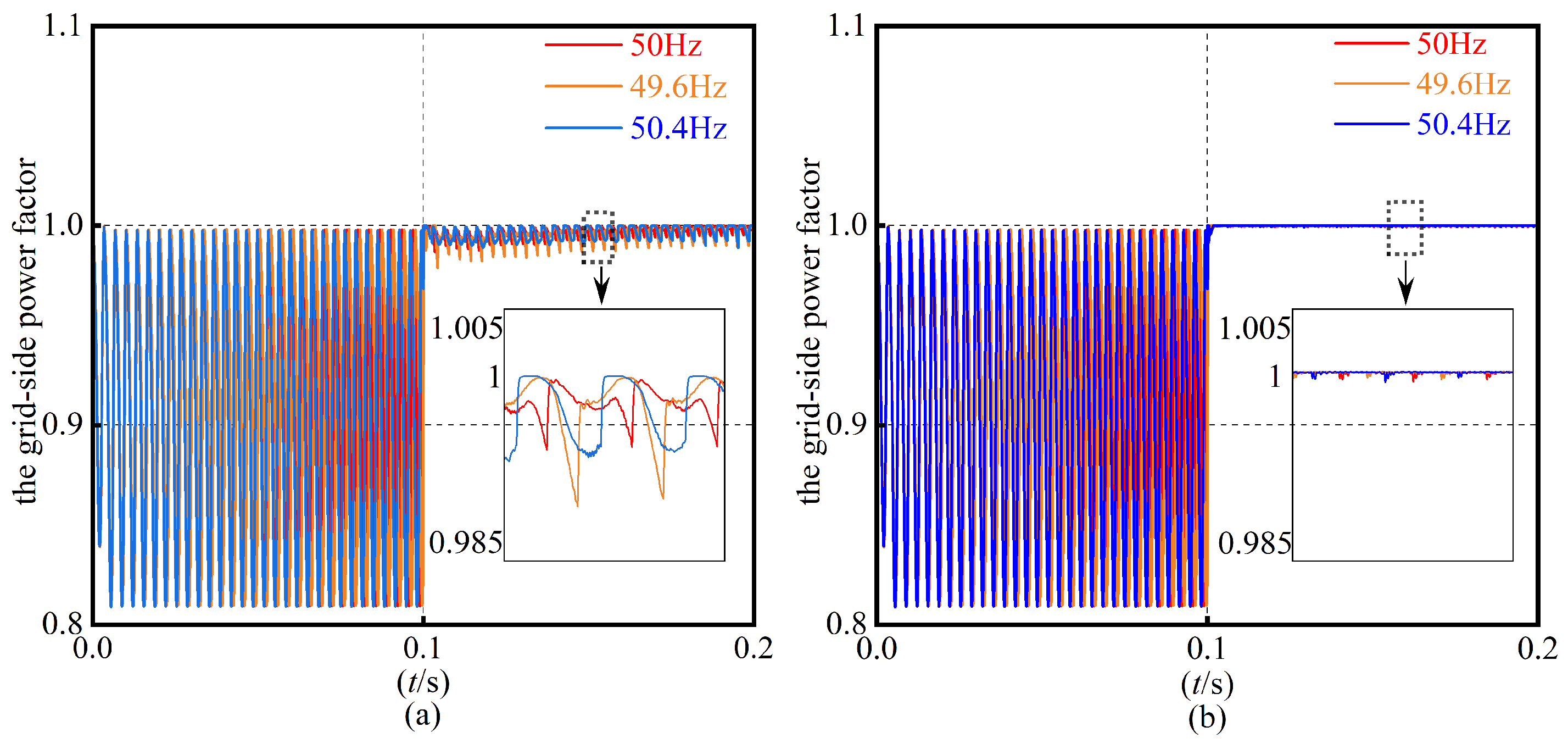
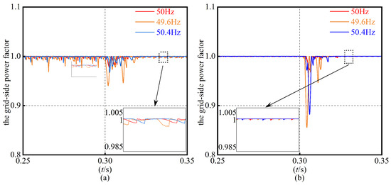
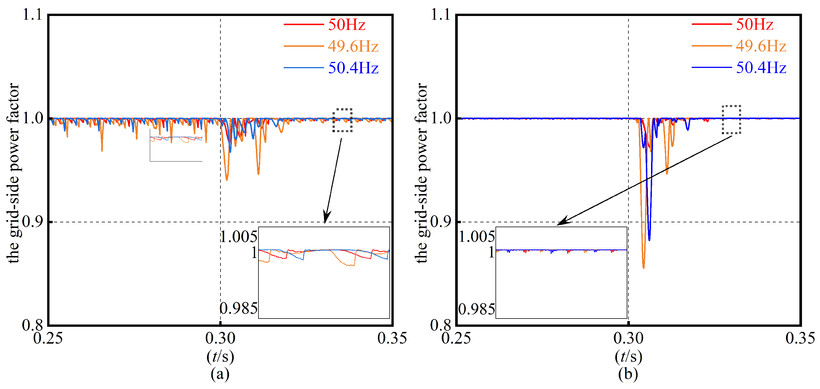
Figure 24 and Figure 25 present the grid-side power factor before and after the harmonic load-switching event. Once the STATCOM is enabled at s, the CRC-based system causes the power factor to fluctuate between approximately 0.98 and 1.00, whereas the FARC maintains it essentially at unity under both nominal and drifting grid frequencies.
Figure 24.
Grid-side power-factor comparison under different grid frequencies. (a) CRC. (b) FARC.
Figure 25.
Grid-side power-factor comparison during harmonic load switching. (a) CRC. (b) FARC.
Table 5 further summarizes the steady-state grid-current THD and power factor over 49.5–50.5 Hz. Across this entire range, the LCL CHB STATCOM with FARC control consistently achieves a lower THD and a power factor close to 1.0, while the CRC-based solution provides insufficient harmonic attenuation and exhibits more noticeable PF deviations. The corresponding THD values are annotated in the harmonic spectrum plots and summarized, together with the power factor, in Table 5, while the power-factor plots include enlarged local views to show the PF deviations more clearly.
Table 5.
Steady-state grid-current THD and power factor under varying grid frequencies.
It should be noted that IEEE 519-2022 [33] evaluates current harmonic distortion at the point of common coupling mainly in terms of total demand distortion (TDD), and the allowable current distortion depends on the short-circuit ratio. For systems below 69 kV, the most stringent current distortion reference limit is commonly 5% when the short-circuit ratio < 20, while a higher limit is allowed for larger short-circuit ratios. Since the present work reports the steady-state grid-current THD obtained from simulation rather than the field-measured TDD at a specified PCC, the comparison with IEEE 519 is used here as an indicative power quality reference. As shown in Table 5, the proposed FARC keeps the grid-current THD within 2.37–3.88% over 49.5–50.5 Hz, which is below the 5% reference limit. In contrast, the CRC results exceed 5% at several off-nominal frequencies. Therefore, the proposed method shows better potential for meeting harmonic grid requirements.
To further examine the robustness of the proposed controller against grid impedance variation, an additional test is performed by increasing the grid-side inductance from to while keeping the controller parameters unchanged. The test is conducted at , , and so that the combined influence of frequency deviation and grid impedance variation can be evaluated. The corresponding THD and PF results are summarized in Table 6.
Table 6.
Robustness test under grid impedance variation.
The results indicate that the proposed FARC still maintains lower grid-current THD than CRC when the grid-side inductance is increased. This verifies that the proposed frequency-adaptive internal model can preserve its harmonic compensation capability under the tested grid impedance variation. The PF values are reported with sufficient significant digits and should be interpreted as ideal simulation results because nonideal factors such as sensor noise and device dead time are not included in the present simulation model.
Overall, the simulation results indicate that the proposed FARC+DB strategy improves harmonic suppression, current tracking, and power-factor regulation over the tested frequency range, harmonic load-switching condition, and grid impedance variation case. Compared with CRC, the proposed method shows better tolerance of frequency deviation and moderate grid impedance variation.
5. Conclusions
A hybrid deadbeat (DB) plus frequency-adaptive repetitive current control strategy has been proposed for an LCL-filtered cascaded H-bridge (CHB) STATCOM in medium-voltage distribution networks. By using weighted average inductor current (WAIC) feedback, the third-order LCL filter is reduced to an equivalent first-order model for current-loop design. On this basis, a Thiran all-pass fractional-delay element is embedded into the plug-in repetitive controller, allowing the repetitive internal model to adapt to noninteger fundamental periods without changing the sampling frequency.
Simulation results for a 10 kV LCL CHB STATCOM verify the effectiveness of the proposed DB+FARC scheme under both nominal and off-nominal grid frequencies. Over the 49.5–50.5 Hz range, the proposed method maintains the grid-current THD within 2.37–3.88%, whereas the CRC-based scheme gives 4.01–6.51%. In particular, the THD is reduced from 5.20% to 2.37% at 49.6 Hz and from 6.51% to 3.56% at 50.4 Hz. The proposed controller also keeps the power factor close to unity, improves current recovery after harmonic load switching, and maintains a lower THD than CRC when the grid impedance is increased to 1.5 times its nominal value.
These results show that the Thiran all-pass FARC improves the frequency robustness, harmonic suppression, and disturbance rejection capability of LCL-filtered CHB STATCOM. The improved power quality support can contribute to more reliable and efficient operation of medium-voltage distribution networks. Nevertheless, the present validation is limited to MATLAB/Simulink simulations. Practical nonidealities, including sensor noise, sampling and computation delays, PWM dead time, device nonlinearities, and parameter uncertainties, may affect controller performance. Future work will focus on hardware in the loop or experimental validation and further robustness evaluation under practical hardware constraints.
Author Contributions
Conceptualization, P.Y., Methodology, P.Y., Software, P.Y., Validation, P.Y., Formal analysis, P.Y., Investigation, L.Z., Resources, L.Z., Data curation, P.Y., Writing—original draft, P.Y., Writing—review & editing, P.Y., Visualization, L.Z., Supervision, L.Z., Project administration, L.Z., Funding acquisition, L.Z. All authors have read and agreed to the published version of the manuscript.
Funding
This research was funded by the 2024 Fundamental Research Project (No. LJ212410154019) of the Educational Department of Liaoning Province and the Liaoning Provincial Science and Technology Plan Joint Program (No. 2025JH2/101800132).
Institutional Review Board Statement
Not applicable.
Informed Consent Statement
Not applicable.
Data Availability Statement
The original contributions presented in this study are included in the article. Further inquiries can be directed to the corresponding author.
Conflicts of Interest
The authors declare no conflicts of interest.
References
- Wang, L.; Chang, C.H.; Prokhorov, A.V. Stability improvement of a two-area power system connected with an integrated onshore and offshore wind farm using a STATCOM. In Proceedings of the 2016 IEEE Industry Applications Society Annual Meeting; IEEE: Piscataway, NJ, USA, 2016; pp. 1–9. [Google Scholar]
- Olajube, A.; Vedula, S.; Omiloli, K.; Anubi, O. Fault-Ride-Through (FRT) Control of a grid-connected Fixed-Speed Wind Energy Conversion System using STATCOM. In Proceedings of the IECON 2024—50th Annual Conference of the IEEE Industrial Electronics Society; IEEE: Piscataway, NJ, USA, 2024. [Google Scholar]
- Wang, H. Submodule Capacitance Dimensioning for Cascaded H-bridge STATCOM with Film Capacitors. In Proceedings of the Annual Conference of China Electrotechnical Society, Xi’an, China, 20–22 September 2024. [Google Scholar]
- Lu, D.; Zhu, J.; Wang, J.; Yao, J.; Wang, S.; Hu, H. A simple zero-sequence-voltage-based cluster voltage balancing control and the negative sequence current compensation region identification for star-connected cascaded H-bridge STATCOM. IEEE Trans. Power Electron. 2017, 33, 8376–8387. [Google Scholar]
- Beyene, Y.B.; Worku, G.B.; Tjernberg, L.B. Developing a novel approach for passive damped LCL filter and controller parameter design using PSO algorithm in VSC-based islanded microgrids. Array 2025, 26, 100414. [Google Scholar] [CrossRef] [Scilit]
- Upadhyay, N.; Padhy, N.P.; Agarwal, P. Grid-current control with inverter-current feedback active damping for LCL grid-connected inverter. IEEE Trans. Ind. Appl. 2023, 60, 1738–1749. [Google Scholar] [CrossRef] [Scilit]
- Li, M.; Xiao, H.; Cheng, M. An adaptive strategy based on repetitive predictive control for improving adaptability of LCL-type grid-connected inverters under weak grid. IEEE Trans. Power Electron. 2021, 37, 2562–2572. [Google Scholar] [CrossRef] [Scilit]
- Ruan, X.; Wang, X.; Pan, D.; Yang, D.; Bao, C. Controller Design for LCL-Type Grid-Connected Inverter with Capacitor-Current-Feedback Active-Damping. In Control Techniques for LCL-Type Grid-Connected Inverters; CPSS Power Electronics Series; Springer: Singapore, 2018. [Google Scholar]
- Mahider, K.I.; Ferfra, M.; Rabeh, R. Optimization of STATCOM PI controller parameters using the hybrid GA-PSO algorithm. In Proceedings of the 2023 IEEE 11th International Conference on Systems and Control (ICSC); IEEE: Piscataway, NJ, USA, 2023; pp. 270–275. [Google Scholar]
- Ram, A.; Sharma, P.R.; Ahuja, R.K. Harmonics mitigation using proportional–resonant controller-based DSTATCOM in distribution system. In Recent Developments in Electrical and Electronics Engineering: Select Proceedings of ICRDEEE 2022; Springer: Berlin/Heidelberg, Germany, 2023; pp. 131–143. [Google Scholar]
- Basnet, H.; Roinila, T. Decoupled Deadbeat Current Controller For STATCOM Application. In Proceedings of the 2024 International Conference on Smart Energy Systems and Technologies (SEST); IEEE: Piscataway, NJ, USA, 2024; pp. 1–6. [Google Scholar]
- Li, J.; Wang, Y. A Compound Repetitive Control Strategy of H14 Three-level Inverter for Bearing Current Suppression in Wind Power System. In Proceedings of the 2021 IEEE 12th Energy Conversion Congress & Exposition—Asia (ECCE-Asia); IEEE: Piscataway, NJ, USA, 2021. [Google Scholar]
- Guo, C.; Zhong, L.; Zhao, J.; Gao, G.; Huang, Y. First-Order and High-Order Repetitive Control for Single-Phase Grid-Connected Inverter. Complexity 2020, 2020, 1094386. [Google Scholar] [CrossRef] [Scilit]
- Chen, W.; Cai, F.; Lin, Q.; Wang, W. Improved PI and Repetitive Controller for Dual-Buck Inverter. In 2020 39th Chinese Control Conference (CCC); IEEE: Piscataway, NJ, USA, 2020. [Google Scholar]
- Yang, Y.; Zhou, K.; Wang, H.; Blaabjerg, F. Analysis and Mitigation of Dead Time Harmonics in the Single-Phase Full-Bridge PWM Converter with Repetitive Controllers. IEEE Trans. Ind. Appl. 2018, 54, 5343–5354. [Google Scholar] [CrossRef] [Scilit]
- Zhou, K.; Wang, D.; Yang, Y.; Blaabjerg, F. Periodic Control of Power Electronic Converters. 2016. Available online: https://digital-library.theiet.org/doi/book/10.1049/pbpo082e (accessed on 1 May 2026).
- Zhao, Q.; Ye, Y.; Xu, G.; Zhu, M. Improved repetitive control scheme for grid-connected inverter with frequency adaptation. IET Power Electron. 2016, 9, 883–890. [Google Scholar] [CrossRef] [Scilit]
- Kurniawan, E.; Prakosa, J.A.; Wang, H.; Wijonarko, S.; Maftukhah, T.; Purwowibowo, P.; Septanto, H.; Pratiwi, E.B.; Rustandi, D. Design of fractional order odd-harmonics repetitive controller for discrete-time linear systems with experimental validations. Sensors 2022, 22, 8873. [Google Scholar] [CrossRef] [Scilit] [PubMed]
- Herran, M.A.; Fischer, J.R.; Gonzalez, S.A.; Judewicz, M.G.; Carugati, I.; Carrica, D.O. Repetitive Control With Adaptive Sampling Frequency for Wind Power Generation Systems. IEEE J. Emerg. Sel. Top. Power Electron. 2014, 2, 58–69. [Google Scholar] [CrossRef] [Scilit]
- Sun, J.; Gong, J.; Chen, B.; Zha, X. Analysis and design of repetitive controller based on regeneration spectrum and sensitivity function in active power filter system. IET Power Electron. 2014, 7, 2133–2140. [Google Scholar] [CrossRef] [Scilit]
- Zou, Z.-X.; Zhou, K.; Wang, Z.; Cheng, M. Frequency-Adaptive Fractional-Order Repetitive Control of Shunt Active Power Filters. IEEE Trans. Ind. Electron. 2015, 62, 1659–1668. [Google Scholar] [CrossRef] [Scilit]
- Abusara, M.; Sharkh, S.; Zanchetta, P. Adaptive repetitive control with feedforward scheme for grid-connected inverters. IET Power Electron. 2015, 8, 1403–1410. [Google Scholar] [CrossRef] [Scilit]
- Zhang, G.; Zhao, Q.; Wang, Y.; Zhang, H.; Zhou, G.; Wang, A.; Wen, S. Fractional Order Feedforward Odd-Harmonic Repetitive Controller for Grid-Tied Inverters in Microgrids. IEEE J. Emerg. Sel. Top. Ind. Electron. 2024, 5, 1508–1518. [Google Scholar] [CrossRef] [Scilit]
- Tan, C.; Chen, Q.; Zhang, L.; Zhou, K. Frequency Adaptive Repetitive Control for Three-phase Four-leg V2G Inverters. IEEE Trans. Transp. Electrif. 2021, 7, 2095–2103. [Google Scholar] [CrossRef] [Scilit]
- Zhang, H.; Zhao, Q.; Wang, S.; Yue, X. Improved repetitive control for an LCL-type grid-tied inverter with frequency adaptive capability in microgrids. Electronics 2023, 12, 1736. [Google Scholar] [CrossRef] [Scilit]
- Liu, Z.; Zhang, B.; Zhou, K.; Yang, Y.; Wang, J. Virtual Variable Sampling Repetitive Control of Single-phase DC/AC PWM Converters. IEEE J. Emerg. Sel. Top. Power Electron. 2018, 7, 1837–1845. [Google Scholar] [CrossRef] [Scilit]
- Tan, C.; Chen, Q.; Zhou, K.; Zhang, L. A Simple High-Performance Current Control Strategy for V2G Three-Phase Four-Leg Inverter With. IEEE Trans. Transp. Electrif. 2019, 5, 695–701. [Google Scholar] [CrossRef] [Scilit]
- He, J.; Li, Y.W.; Xu, D.; Liang, X.; Liang, B.; Wang, C. Deadbeat weighted average current control with corrective feed-forward compensation for microgrid converters with nonstandard LCL filter. IEEE Trans. Power Electron. 2016, 32, 2661–2674. [Google Scholar] [CrossRef] [Scilit]
- He, L.; Zhang, K.; Xiong, J.; Fan, S. A Repetitive Control Scheme for Harmonic Suppression of Circulating Current in Modular Multilevel Converters. IEEE Trans. Power Electron. 2014, 30, 471–481. [Google Scholar] [CrossRef] [Scilit]
- Laakso, T.I.; Valimaki, V.; Karjalainen, M.; Laine, U.K. Splitting the unit delay [FIR/all pass filters design]. IEEE Signal Process. Mag. 1996, 13, 30–60. [Google Scholar] [CrossRef] [Scilit]
- Vlimki, V.; Laakso, T.I. Principles of fractional delay filters. In Proceedings of the IEEE International Conference on Acoustics, Speech, and Signal Processing; IEEE: Piscataway, NJ, USA, 2000. [Google Scholar]
- Ye, J.; Liu, L.; Xu, J.; Shen, A. Frequency Adaptive Proportional-Repetitive Control for Grid-Connected Inverters. IEEE Trans. Ind. Electron. 2020, 68, 7965–7974. [Google Scholar] [CrossRef] [Scilit]
- IEEE Std 519-2022; IEEE Standard for Harmonic Control in Electric Power Systems. IEEE: New York, NY, USA, 2022.

Disclaimer/Publisher’s Note: The statements, opinions and data contained in all publications are solely those of the individual author(s) and contributor(s) and not of MDPI and/or the editor(s). MDPI and/or the editor(s) disclaim responsibility for any injury to people or property resulting from any ideas, methods, instructions or products referred to in the content. |
© 2026 by the authors. Licensee MDPI, Basel, Switzerland. This article is an open access article distributed under the terms and conditions of the Creative Commons Attribution (CC BY) license.