


Abstract
Underground Gas Storage (UGS) is transitioning from traditional fossil fuel peak-shaving facilities into comprehensive hubs for Terawatt-hour-scale Terawatt-hour (TWh) scale renewable energy storage. The unique physicochemical properties of diverse fluids, such as the negative Joule–Thomson coefficient of hydrogen (−0.03 K/bar), present complex engineering adaptability challenges. Since existing studies primarily focus on single mechanisms or specific geological types, this review integrates a unified engineering framework to evaluate the repurposing potential and retrofitting requirements of existing oil and gas assets. By compiling a property benchmarking matrix for methane, carbon dioxide, and hydrogen, the storage adaptability of various geological formations is summarized. Salt caverns exhibit strong adaptability to highly diffusive and reactive fluids due to their high salinity (exceeding 150 g/L) and mechanical stability, whereas porous media offer massive capacity (more than 10 times) but require overcoming severe biogeochemical obstacles. Based on thermo–hydro–mechanical–chemical–biological (THMCB) coupling mechanisms, an integrity evaluation system for artificial wellbore and natural geological barriers is systematically reviewed. Critical risks, including fatigue failure under high-frequency cyclic loading, material degradation, gas leakage, and indirect Global Warming Potential (GWP), are elucidated. A future evolution route integrating physical, digital, and policy dimensions is outlined. This roadmap emphasizes Hydrogen-Enriched Compressed Natural Gas (HCNG)synergistic storage, dynamic risk control utilizing digital twins and Artificial Intelligence (AI), and standardized Life Cycle Assessment mechanisms (LCA), providing a scientific basis for the sustainable transition of UGS facilities.
1. Introduction
As a core infrastructure for balancing energy supply and demand fluctuations and ensuring national energy security, Underground Gas Storage (UGS) has an industrial application history of over a century since the commissioning of the world’s first facility in the Welland gas field, Canada, in 1915 [1]. Within the traditional fossil fuel system, UGS plays a critical regulatory role. On the demand side, it manages winter heating surges through seasonal peak shaving. On the supply side, it mitigates risks associated with upstream production disruptions and stabilizes price fluctuations [2]. Following a century of engineering practice encompassing geological site selection, injection-production operations, and risk monitoring, the UGS industry has established a highly standardized engineering paradigm, represented by practices such as API 1170 and 1171 [3,4,5,6,7,8]. This standardization provides a robust foundation for the stability of modern energy systems.
However, the acceleration of global climate action is driving a profound transition in the energy sector from fossil fuel dominance to renewable-based low-carbon systems. By January 2023, atmospheric CO2 concentrations reached a historical peak of 416.8 ppm, 135 ppm above pre-industrial levels, compelling nations to accelerate carbon neutrality processes [9]. Under these circumstances, traditional UGS faces severe sustainability challenges. Sole reliance on natural gas for peak shaving is inadequate for future power grids with high renewable penetrations. The inherent intermittency and randomness of solar and wind energy cause temporal supply-demand mismatches on the gigawatt or even Terawatt-hour (TWh) scale [10,11,12]. Consequently, UGS functions must upgrade from single-purpose fossil fuel reserves into large-scale green energy hubs capable of accommodating clean energy carriers. This transition represents not merely a shift in market demand but a rigorous test of the adaptability of existing underground engineering facilities. Given its high energy density and cross-seasonal storage potential, hydrogen is identified as a critical carrier for the sustainable transition of UGS [13].
To elucidate the urgency of the global energy transition, Figure 1 illustrates natural gas market trends alongside the concurrent demand for carbon dioxide storage. This trajectory highlights a fundamental paradigm shift. While natural gas remains a crucial transitional fuel in the short term, its demand will inevitably decline post-peak [14]. This decline aligns with the exponential penetration of hydrogen required to ultimately achieve carbon neutrality. Concurrently, deploying carbon capture, utilization, and storage technologies necessitates a proportional expansion in carbon dioxide storage capacity. The inflection point identified around 2038 signifies a critical transition window [15]. It emphasizes the urgent need to retrofit and repurpose existing underground geological storage infrastructure to accommodate the distinctly different physicochemical properties of hydrogen and carbon dioxide.
Figure 1.
Projected global market evolution for gas energy and CO2 storage demand (2020–2060).
However, switching the storage medium from methane to hydrogen is not a simple extrapolation of engineering parameters. The unique physicochemical properties of hydrogen, including extremely low viscosity, high diffusivity, and strong reducing capacity, exceed the operational boundaries of traditional UGS. Existing geological storage theories and wellbore integrity standards may fail in pure or blended hydrogen environments [16]. For instance, API Class G [17] cement designed for natural gas may experience microstructural degradation in hydrogen-rich environments [18,19], while standard carbon steel tubulars face severe risks of Hydrogen Embrittlement (HE). Consequently, the engineering community is currently addressing a core question regarding the extent to which existing infrastructure and technological systems can be repurposed and identifying specific areas that require systematic retrofitting.
Despite the rapid growth of literature on UGS, current research remains highly fragmented. Existing studies are largely conducted independently within specific disciplines, focusing either on particular lithologies, such as salt rock geomechanics, or on single mechanisms, like microbial dynamics. Consequently, a comprehensive review of how UGS engineering systems can address these sustainability challenges is lacking. To bridge this gap, this review integrates a unified, future-oriented engineering framework based on the latest global theoretical research and engineering practices. It objectively evaluates the multi-fluid compatibility of existing oil and gas assets and their requirements for technological iteration. This framework comprises four core dimensions:
- Section 2 establishes an applicability matching mechanism that compiles a property benchmarking matrix for methane, carbon dioxide, and hydrogen to determine the optimal suitability of different geological formations, including salt caverns, depleted reservoirs, and aquifers, for specific gas storage scenarios.
- Section 5 proposes a multidimensional feasibility analysis that incorporates economic viability, advanced measurement, monitoring, and verification frameworks addressing both deep reservoir and potential surface effects, life-cycle safety, and quantitative site selection criteria to explore large-scale implementation pathways for transitioning UGS toward multi-medium synergistic storage.
Notably, a critical functional distinction must be established between carbon dioxide in the context of UGS transition and traditional Carbon Capture and Storage (CCS). While CCS primarily targets the permanent and irreversible sequestration of carbon dioxide in deep saline aquifers, the carbon dioxide discussed within this unified engineering framework serves as a functional medium—an engineering asset—supporting the cyclic efficiency of energy carriers such as methane and hydrogen. It functions either as a cushion gas to provide pressure support within depleted gas reservoirs or as a constituent in Hydrogen-Enriched Compressed Natural Gas (HCNG) and geological methanation reactions. Consequently, the engineering emphasis shifts from long-term plume stabilization to evaluating the behavior of carbon dioxide regarding formation pressure maintenance and biochemical participation under dynamic pressure cycling rather than its permanent geological disposal as a greenhouse gas.
2. Fundamentals of Underground Gas Storage
2.1. Geological Structure Classification
Underground energy storage systems utilize geological formations to achieve the gas-tight containment of fluids. These formations are primarily classified into porous media, including depleted oil and gas reservoirs and aquifers, and cavernous structures, such as salt domes or bedded salt formations (Figure 2). The natural gas storage industry has established a mature global network comprising approximately 689 operational facilities worldwide as of 2023 [20]. Depleted oil and gas reservoirs constitute the primary storage source, accounting for 79.62% of the working gas volume, followed by aquifers at 11.35% and salt caverns [21]. Despite this operational maturity, the transition of UGS remains significantly constrained by lithological factors. Currently, the commercial storage of single, high-purity media relies heavily on salt caverns. Conversely, the application focus for porous media has shifted toward verifying the compatibility of mixed gas systems, such as HCNG [22,23].
Figure 2.
Schematic cross-section of the three primary geological structures for Underground Gas Storage. Green regions denote the stored gas phase (including working gas and cushion gas); light blue regions indicate native formation water; and the white region within the salt formation represents the solution-mined storage cavern void.
Depleted oil and gas reservoirs provide geologically proven sealing integrity derived from millions of years of hydrocarbon confinement. Typically, these reservoirs are characterized by well-defined structural or stratigraphic traps with a proven geological history of fluid confinement, featuring high-quality reservoir rocks and robust, tested top seals. Their brownfield nature permits the repurposing of existing surface and subsurface infrastructure, significantly reducing Capital Expenditures (CAPEX) [24,25,26]. The core economic advantage of these facilities lies in the native cushion gas, which typically occupies 40% to 50% of the reservoir volume. This pre-existing gas substantially minimizes the costs associated with injecting buffer gas to maintain formation pressure. However, the fluid legacy effects in depleted reservoirs create a complex geochemical environment. Although residual hydrocarbons offer a physical buffer, they may experience thermodynamic disequilibrium with newly injected reactive gases and consequently induce secondary reactions [27,28].
Aquifers are porous and permeable water-bearing formations distributed widely worldwide with massive theoretical storage capacities. They provide strategic storage options for regions lacking salt rock or hydrocarbon resources [26,29,30]. A functional distinction exists between porous aquifers, which offer relatively uniform storage via intergranular porosity, and fractured aquifers, where fluid storage and transport are dominated by discrete fracture networks, potentially increasing the risk of preferential flow and sealing uncertainties. Unlike depleted reservoirs, aquifers lack detailed geological production histories. Consequently, they require substantial exploration expenditures to verify caprock tightness. Furthermore, displacing native pore water requires an exceptionally high proportion of cushion gas, reaching up to 80% of the total volume. This requirement results in prohibitive initial injection costs. Compared to the relatively stable fluid properties of methane and carbon dioxide, hydrogen exhibits extreme density and viscosity contrasts. These contrasting properties significantly reduce hydrodynamic stability at the gas–water interface and make the system highly susceptible to viscous fingering [31,32,33,34,35].
Furthermore, cyclic gas injection and withdrawal operations in these porous formations trigger transient pore pressure fluctuations and effective stress variations at depth, which may further manifest as measurable geomechanical effects on the surface, such as ground uplift or subsidence. This will be discussed in detail in Section 3.4 and Section 4.2.
Salt caverns are currently the industrially verified geological formations exhibiting optimal comprehensive performance to simultaneously meet high-pressure, high-frequency, and high-purity requirements [22,36,37]. Rock salt possesses extremely low permeability below 10−20 m2 and unique viscoplastic self-healing characteristics, which almost eliminate the probability of gas escaping along fractures. Furthermore, its inert geochemical environment effectively suppresses microbial activity. Salt caverns support high-frequency injection and withdrawal cycles ranging from 6 to 12 times annually, making them ideal options for smoothing short-term power grid fluctuations [38,39,40]. Their primary limitations are uneven geographical distribution and the restricted volumetric capacity of individual caverns, typically ranging from 104 to 105 m3 [41,42].
Beyond the three mainstream types, alternative structures, including lined rock caverns and repurposed abandoned mines, are under investigation, though they continue to face economic challenges for large-scale deployment [43,44]. Lined rock caverns utilize artificial steel or concrete linings to seal gas within hard rock excavations, such as granite. This design provides siting flexibility unconstrained by specific geological features. Nevertheless, high construction costs currently restrict their application to small-scale and high-value scenarios. Repurposing abandoned mines to expand underground energy storage capacity represents a unique pathway for the low-carbon technology transition in Europe. Although these facilities offer pre-existing underground space, they pose severe social and environmental challenges. High-pressure gas injection may drive the migration of residual mine water containing heavy metals and acidic substances, consequently contaminating shallow groundwater systems [45,46,47,48,49]. Therefore, establishing strict hydraulic barriers and pollutant monitoring systems is widely considered a critical prerequisite for the commercial deployment of mine repurposing projects.
These distinct lithological specificities and sealing mechanisms form the geological foundation for the differentiated risk assessment and site selection strategies detailed later in Section 5.3.
2.2. Gas Property Benchmarking
The transition from methane storage or carbon dioxide capture to hydrogen storage typically requires a comprehensive consideration of the inherent physicochemical property differences among these gases. Methane provides an ideal inert baseline. Carbon dioxide exhibits acidic characteristics coupled with high density and high solubility. Conversely, hydrogen represents the opposite extreme, characterized by low viscosity and high diffusivity (Table 1). These distinct physical properties dictate that UGS systems must possess corresponding engineering adaptability.
Table 1.
Physicochemical properties benchmarking of methane, carbon dioxide and hydrogen (20 °C, 1 atm).
Hydrogen is the lowest-density gas known. Its density under standard conditions, 0.084 kg/m3, is approximately one-eighth that of methane [50]. This physical characteristic creates a critical trade-off between gravimetric and volumetric energy densities. Although hydrogen serves as the gaseous fuel with the highest heating value per unit mass, its volumetric heating value remains extremely low, equating to approximately one-third that of natural gas and one-twentieth that of hard coal [51]. Consequently, generating an equivalent energy output requires substantially increasing the underground hydrogen storage volume or elevating the operating pressure, given the volumetric heating values of 12.7 MJ/m3 for hydrogen and 40 MJ/m3 for methane. Although liquefaction can mitigate these volumetric constraints, the extremely low critical temperature of hydrogen makes this process cost-prohibitive. Therefore, current underground storage strategies focus primarily on the high-pressure gaseous phase rather than the liquid phase. In subsurface environments, the massive density contrast between hydrogen and formation brine generates strong buoyancy. This buoyancy drives rapid upward gas migration and forms a gas cap beneath the caprock, imposing extremely stringent requirements on the vertical sealing capacity of the trap structure [34,52].
Regarding fluid dynamics, hydrogen exhibits an extremely low viscosity of approximately 8.8 μPa·s, which is significantly lower than that of methane, carbon dioxide, or formation water. Although this high mobility facilitates rapid transport within porous media, it generates a highly unfavorable mobility ratio. Consequently, this condition makes the system highly susceptible to viscous fingering and destabilizes the displacement front, contrasting sharply with the relatively stable piston-like displacement observed in carbon dioxide capture. Thermodynamically, hydrogen possesses high thermal conductivity and a negative Joule–Thomson coefficient at typical storage temperatures. This coefficient dictates that the gas temperature increases during throttling expansion, and this anomalous thermal effect directly impacts wellhead thermal management strategies [53,54,55]. Geochemically, hydrogen is a non-polar molecule with limited aqueous solubility. Unlike carbon dioxide, it does not form carbonic acid to cause sharp pH reductions. While this characteristic mitigates the risk of acidic mineral dissolution, it shifts the primary safety threat from geochemical dissolution to biogeochemical consumption.
While this section benchmarks the bulk physical attributes of methane, carbon dioxide, and hydrogen, their complex reactive behaviors and evolutionary mechanisms when sequestered within deep geological formations are further dissected under the geochemical coupling framework in Section 4.1.
2.3. Global Representative Projects
Global engineering practices for the renewable energy transition of UGS exhibit a dichotomous pattern comprising mature salt cavern facilities and experimental porous media pilot projects.
Salt cavern storage has established the industry safety benchmark. Since its operation began in 1983, the Clemens Dome storage facility in the United States has completed over 60,000 pressure cycles ranging from 7.0 to 13.5 MPa. This facility records a leakage rate below 0.05% and an availability rate of 99.8% [56]. Similar infrastructure, including the Spindletop facility and the ACES Delta project, commissioned in 2023, further validates the feasibility and extremely low loss rates of UGS technological systems when accommodating TWh-scale clean energy carriers. Simultaneously, Europe is accelerating the large-scale deployment of this technology through projects such as HyStock in the Netherlands.
In contrast, porous media projects primarily focus on verifying the containment capacity and retrofitting potential of existing UGS facilities for mixed gas systems, including town gas and HCNG. Early initiatives, such as the Lobodice project in the Czech Republic and the Beynes project in France, revealed severe biological challenges. Historical records indicate that microbial conversion of hydrogen into methane and hydrogen sulfide resulted in hydrogen loss rates reaching 17% to 20% within a single year [57,58,59]. The recent Underground Sun Storage project in Austria successfully transitioned from pilot-scale characterization of microbial consumption rates to commercial operations with a capacity of 4.2 gigawatt hours. Furthermore, this project introduced the engineering concept of utilizing in situ microorganisms for geological methanation [60]. Concurrently, the deployment of underground hydrogen storage (UHS) in Asia is entering an accelerated phase, highlighted by the Pingdingshan salt cavern project and extensive porous media screening across major basins in China [61,62,63].
A comprehensive review of global representative underground energy storage projects, summarized in Table 2, reveals significant disparities in commercial maturity. Although historical cases demonstrate successful town gas storage in porous media, current pure hydrogen pilot projects predominantly utilize salt caverns. This trend highlights a critical industry consensus. The geomechanical tightness of salt caverns is well-proven. However, unlocking the significantly larger storage potential within depleted reservoirs and aquifers remains constrained by unresolved biogeochemical and multiphysics uncertainties.
Table 2.
Summary of global representative Underground Gas Storage projects.
3. Wellbore Integrity Issues
Serving as the conduit connecting surface facilities to subsurface reservoirs, the wellbore represents a highly vulnerable component within the UGS system. Statistics indicate that wellbore seal failures account for over 50% of UGS safety incidents [64,65]. The failure modes of wellbore barriers exhibit a distinct evolutionary trajectory as the storage medium changes. In traditional methane environments, failure risks primarily originate from low-frequency mechanical fatigue and erosion. Following the introduction of carbon dioxide, the primary threat shifts to electrochemical corrosion, specifically carbonic acid corrosion in wet environments. With the integration of hydrogen, the operational paradigm transitions from seasonal peak shaving to the high-frequency balancing of renewable energy. Consequently, next-generation energy storage wellbore systems face multiple compounded challenges. These include high-frequency thermo-mechanical fatigue, atomic-scale material degradation, and multiphysics coupling risks, as illustrated in Figure 3.
Figure 3.
Schematic of potential wellbore integrity failure mechanisms and leakage pathways in Underground Gas Storage systems.
3.1. Metallic Barrier Degradation
3.1.1. Hydrogen Embrittlement
Steel casing and tubing serve as the primary defense line against leakage. However, they face substantial risks of HE in hydrogen environments [66,67,68,69,70]. This degradation process initiates with the adsorption and dissociation of hydrogen molecules on the steel surface. The resulting atomic hydrogen diffuses into the metal lattice and accumulates at internal defects, including grain boundaries and dislocations. This localized accumulation reduces the cohesive energy of metallic bonds, subsequently driving a material transition from ductile to brittle fracture. In low-strength steels, the accumulated atomic hydrogen may recombine into molecular hydrogen at inclusion sites. This recombination generates localized extreme internal pressure, consequently inducing hydrogen-induced cracking or hydrogen blistering.
A systematic evaluation by Gong et al. [71] indicated that the ultimate tensile strength serves as a critical control parameter. High-strength steels with an ultimate tensile strength exceeding 1000 MPa exhibit extreme susceptibility to HE. They suggested that low-carbon steels with a carbon content below 0.3% are generally safe, provided the hydrogen partial pressure remains below 20 bar and the hydrogen concentration in the gas mixture is under 10%. However, pure hydrogen environments necessitate the use of specialized alloys. Furthermore, research by Chen et al. [72] on B1500HS boron steel revealed that performance degradation induced by low hydrogen concentrations is reversible. Once a critical concentration is exceeded, it causes permanent plasticity loss.
The complexity of subsurface environments stems from the interactions among multi-component gases. Molecular Dynamics (MD) simulations by Lu et al. [73] revealed an intriguing phenomenon in HCNG. Methane molecules compete with hydrogen for adsorption sites on the iron surface. This competition inhibits the dissociation and permeation of hydrogen atoms, effectively acting as a physical shield. Conversely, the presence of carbon dioxide and hydrogen sulfide significantly exacerbates corrosion risks.
In summary, the underlying failure mechanisms of HE primarily involve atomic hydrogen diffusion and the subsequent reduction in lattice cohesive energy, which triggers a macro-scale transition from ductile to brittle fracture. Key influencing factors are categorized into material vulnerability—specifically high tensile strength (>1000 MPa) and carbon content (>0.3%)—and environmental variables, including high hydrogen partial pressure and concentration. To prevent such failures, industry strategies emphasize selecting low-strength or low-carbon steels, implementing grain refinement to trap diffusible hydrogen, and strategically leveraging the competitive adsorption of methane in HCNG blends as a natural inhibitory shield.
3.1.2. Microbially Induced Corrosion
Microbial communities in subsurface environments constitute a hidden threat to metallic barrier integrity. A warning by Gu et al. [74] identified Sulfate-Reducing Bacteria (SRB) as a primary agent of microbiologically influenced corrosion. Under anaerobic conditions, these bacteria utilize hydrogen as an electron donor to reduce sulfates into hydrogen sulfide. This biochemical process introduces a dual hazard.
- Hydrogenase beneath the bacterial biofilm catalyzes the cathodic depolarization reaction, thereby accelerating the anodic dissolution rate of the iron matrix.
- The metabolic byproduct hydrogen sulfide acts as a typical hydrogen recombination poison. It impedes the recombination of adsorbed atomic hydrogen into molecular hydrogen on the steel surface. This impedance consequently forces excessive atomic hydrogen to diffuse into the steel matrix. Sulfide stress corrosion cracking induced by this biogenic hydrogen sulfide typically exhibits far greater destructiveness than purely abiotic corrosion.
Effective prevention measures focus on environmental boundary control—such as maintaining high formation water salinity (>150 g/L) to induce osmotic inactivation of bacteria—and the deployment of advanced isotopic tracing to provide early warnings of microbial metabolic activity before macroscopic integrity is compromised.
3.2. Cement Sheath Integrity
3.2.1. Chemical Alteration
API Class G cement, commonly utilized in oil and gas wells, primarily consists of calcium silicate hydrate and calcium hydroxide. Research by Al-Yaseri et al. [75] indicated that hydrogen molecules remain thermodynamically inert at temperatures below 600 °C due to their strong bond energy. Consequently, hydrogen does not readily react directly with the cement matrix. The primary chemical threat originates from carbonation reactions induced by associated carbon dioxide. Dissolved carbon dioxide reacts with calcium hydroxide to precipitate calcium carbonate. In water-rich environments, this precipitate further converts into soluble calcium bicarbonate. This dissolution and leaching process increases the porosity and degrades the mechanical strength of the cement matrix, making it more susceptible to failure under alternating stresses. Furthermore, theoretical models suggest that hydrogen may reduce the iron phases or sulfate components within the cement under specific high-temperature and high-pressure conditions. Although the reaction kinetics remain relatively slow at conventional reservoir temperatures, the long-term cumulative effects warrant rigorous attention [76,77].
At the microscopic level, MD simulations provide a novel perspective for understanding hydrogen transport within the cement matrix. A recent study by Hubao et al. [78] indicates that the diffusion of hydrogen molecules at the interface of cement hydration products, specifically calcium silicate hydrate gels, follows a hopping mechanism. Incorporating nanomaterials, including graphene oxide and carbon nanotubes, significantly alters this diffusion pathway. During the early stages of hydration, these nanomaterials serve as nucleation sites. This nucleation promotes the growth of high-density calcium silicate hydrate gels, consequently refining the nanoscale pore structure. Furthermore, MD simulations elucidate the microscopic barrier mechanisms. Organic polymer additives introduce steric hindrance, which significantly increases the tortuosity of the diffusion path and effectively retards the migration of hydrogen molecules [79,80,81,82]. These findings provide theoretical guidance at the molecular level for developing next-generation low-permeability cement barriers.
3.2.2. Pore Gas Migration
The sealing capacity of the cement sheath depends on its pore structure and interfacial bonding quality. Gas migration within the cement primarily follows two mechanisms, specifically Darcy flow and Fickian diffusion. This migration is strictly controlled by pore water saturation. The threshold pressure theory proposed by Thaysen et al. [83] indicates that hydrogen displacing pore water in cement with a permeability of 0.1 mD must overcome a capillary resistance of approximately 0.14 MPa. Measurement data from Sercombe et al. [84] demonstrate that the diffusion coefficient of hydrogen in dry cement is approximately 10−6 m2/s. However, Liu et al. [85] discovered a dramatic shift under water-saturated conditions exceeding a 60% saturation level. Due to the low solubility of hydrogen in water, the effective diffusion coefficient plummets from 10−6 to 10−13 m2/s. This physical phenomenon suggests a potential engineering strategy. Maintaining high water saturation within the cement sheath leverages the low solubility of hydrogen in pore water. This approach establishes a hydraulic sealing mechanism to effectively inhibit the microscopic diffusion of gas molecules.
3.3. Elastomer Seal Failure
3.3.1. Rapid Gas Decompression
Due to its extremely high diffusion rate, hydrogen more readily permeates downhole elastomer seals. Under Rapid Gas Decompression (RGD) conditions, this permeation induces explosive decompression failure. During the high-pressure injection phase, minute hydrogen molecules permeate and saturate the free volume of the polymer. When the system experiences RGD, such as during emergency shut-ins or withdrawal phases, the expansion rate of the dissolved gas within the polymer significantly exceeds its outward diffusion rate. This delayed gas expansion generates internal tensile stresses that exceed the tear strength of the material. Consequently, it causes internal blistering, cracking, and even structural fragmentation within the seal. Experiments by Jeon et al. [86] confirmed that the swelling degree of nitrile butadiene rubber is directly proportional to the hydrogen partial pressure, ranging from 0.7 to 100 MPa. Their observations reiterated that during rapid system depressurization, the expansion rate of hydrogen dissolved within the polymer outpaces its diffusion rate, ultimately leading to internal blistering and rupture.
To mitigate gas permeation, the industry frequently employs carbon black or nano-silica as reinforcing fillers. These fillers form strong interactions with polymer chains, creating bound rubber. This interaction restricts the Brownian motion of the chain segments, thereby reducing the free volume. However, the addition of fillers involves a critical threshold. Excessive filler content can significantly enhance the Payne effect. Under dynamic high-pressure cycling, this effect weakens the interfacial bonding between the filler and the matrix, ironically turning these interfaces into nucleation sites for microcrack initiation. Therefore, balancing the physical barrier properties of the filler with its interfacial bonding strength remains a core challenge in elastomer modification.
3.3.2. Chemical Swelling
Beyond physical damage, chemical compatibility presents a significant challenge. An evaluation of acidic gas effects by Yun et al. [87] revealed that hydrogen sulfide primarily induces hardening and brittle fracture in nitrile butadiene rubber. Conversely, supercritical carbon dioxide causes severe swelling and plasticization. Although hydrogen itself is non-polar and does not initiate significant chemical swelling, coexisting gases pose a substantial probability of inducing packer failure.
A comparative material selection study by Jung et al. [88] demonstrated that fluoroelastomers exhibit superior resistance to hydrogen permeation and RGD. Ethylene propylene diene monomer rubber ranks second in performance. In contrast, the nitrile butadiene rubber widely applied in the oil and gas industry remains highly susceptible to hydrogen-induced blistering failure. Consequently, the selection logic for wellbore sealing materials must shift toward fluoroelastomers or hydrogenated nitrile butadiene rubber, which better withstand harsh operational conditions. However, engineering decisions typically necessitate a rigorous techno-economic trade-off between the exceptional permeation resistance of fluoroelastomers and their prohibitive material costs.
3.4. Thermo-Mechanical Fatigue
As illustrated in Figure 4, traditional natural gas storage follows predictable and smooth seasonal cycles. To accommodate the fluctuations of intermittent renewable energy, next-generation UGS will increasingly adopt high-frequency injection and withdrawal modes, specifically daily or weekly cycles. Influenced by the inherent intermittency of renewable sources, these storage operations exhibit irregular, high-frequency fluctuations. These noisy time-series dynamics subject the reservoir rock and wellbore to repeated alternating stresses and continuous thermal shocks. Consequently, this process significantly amplifies thermo-mechanical fatigue and disrupts the thermodynamic steady state associated with traditional seasonal peak shaving. Ultimately, it induces asynchronous deformation within the casing, cement sheath, and formation system.
Figure 4.
Comparison of operational gas inventory dynamics between traditional natural gas storage and future renewable-driven underground hydrogen storage.
3.4.1. Injection Phase
It is important to note that the thermo-mechanical fatigue at the wellbore-formation interface is a universal challenge across all UGS architectures. However, the magnitude of the micro-annulus formation and subsequent gas leakage is highly sensitive to reservoir-specific operational profiles, such as the high-pressure injection rates typical of salt caverns compared to the relatively lower rates in porous media.
Experimental research by Stormont et al. [89] demonstrated that during fluid injection phases with significant temperature differentials, the coefficient of thermal expansion for steel, approximately 12 × 10−6/°C, slightly exceeds that of cement, which is approximately 10 × 10−6/°C. Consequently, casing shrinkage generates tensile stress at the cement interface. They observed that the hydraulic aperture of the micro-annulus increases as the temperature decreases. Furthermore, the magnitude of this variation exceeds the predicted values of linear thermoelastic theory. This discrepancy indicates that microcrack propagation may have already occurred within the cement sheath, thereby providing pathways for fluid leakage. Numerical simulations by Xu et al. [90] demonstrated that the coupling of cold injection and high pressure constitutes the most hazardous operational condition. Cooling-induced shrinkage drives the detachment of the cement from the formation. Simultaneously, injection pressure applies potent shear forces. This coupling accelerates the irreversible accumulation of plastic deformation. Subsequently, it may form permanent leakage channels, causing the permeability to increase exponentially with the number of operational cycles.
3.4.2. Withdrawal Phase
During the withdrawal phase, thermal recovery causes the casing to expand, applying radial compressive stress to the cement sheath. Cementitious materials inherently possess brittle characteristics featuring low tensile and high compressive strengths. Consequently, repeated alternating tensile and compressive stresses induce a hysteresis effect in plastic deformation. Large-scale physical model tests conducted at the TNO laboratory by Corina et al. [91] also confirmed that dynamic pressure cycling significantly alters the hydraulic conductivity of the micro-annulus. Further quantification by Kuanhai et al. [92] highlighted the destructive impact of thermal cycling. They discovered that the tensile bond strength at the cement-casing interface decreased significantly after merely eleven thermal cycles with temperature differentials exceeding 120 °C. While these alternating stress cycles pose a systemic threat to all UGS types, the failure trajectory is uniquely modulated by the host rock geology: in porous media, the fatigue response is primarily governed by the poroelastic deformation of the reservoir matrix under rapid pressure drawdown, whereas wellbores within salt rock formations endure non-uniform external compressive loads generated by salt rock creep. If the casing design fails to adequately account for the anisotropic rheological properties of the salt rock, the risks of casing collapse or shear deformation increase substantially, ultimately triggering wellbore obstruction.
4. Geostorage Integrity Issues
The geological system, comprising reservoir rocks and the overlying impermeable caprock, serves as the natural barrier preventing gas escape [93]. The subsurface geological environment exhibits extreme sensitivity to fluid properties. Using chemically inert methane as a baseline, the introduction of carbon dioxide initiates acidic dissolution mechanisms. Furthermore, hydrogen introduces strong reducing capacity and biological metabolic activity. This thermodynamic spectrum transition from inert to reactive states triggers complex thermo–hydro–mechanical–chemical–biological (THMCB) coupled responses within the subsurface. Consequently, evaluating geological integrity requires more than merely assessing macroscopic structural stability. It necessitates quantifying the dynamic impacts of microscale biogeochemical alterations on petrophysical properties, as illustrated in Figure 5.
Figure 5.
Multiscale illustration of key geological integrity risks and leakage pathways in Underground Gas Storage.
4.1. Geochemical Interactions
Injecting highly reactive gases into deep geological formations inevitably disrupts the original subsurface equilibrium. Building upon the fundamental properties established in Section 2.2, this section transitions from bulk gas characteristics to multiscale geochemical interactions. As summarized in Table 3, the subsequent reactions are broadly categorized into abiotic and biotic processes. Abiotic mineral alterations typically proceed at slow kinetic rates and primarily modify the formation porosity. Conversely, biotic pathways pose severe operational threats. These pathways are predominantly driven by indigenous microorganisms through methanogenesis and sulfate reduction. These microbial activities massively consume the stored hydrogen and generate corrosive byproducts. Consequently, they severely compromise both the economic viability and the purity of the recovered gas.
Table 3.
Summary of key biogeochemical reactions in Underground Gas Storage.
4.1.1. Abiotic Mineral Reactions
The chemical stability of geological formations depends on the thermodynamic equilibrium of the fluid-rock system. Methane generally exhibits chemical inertness, enabling long-term coexistence with rock minerals. Carbon dioxide tends to hydrolyze and produce carbonic acid, consequently initiating acidic dissolution. Conversely, hydrogen acts as a strong electron donor that tends to disrupt the original redox equilibrium and induce reductive reactions.
Under standard subsurface temperature and pressure conditions, hydrogen molecules exhibit kinetic inertness toward most rock-forming minerals. However, acting as a potent reducing agent, hydrogen initiates redox reactions within formations rich in oxidized minerals. Experiments conducted by Ahmadpour et al. [94] indicated that in reservoirs containing pyrite or hematite, the reduction of pyrite constitutes a critical reaction. Hydrogen can reduce ferric iron to ferrous iron and sulfates to sulfides, subsequently generating highly toxic hydrogen sulfide. This process not only consumes the stored hydrogen but also alters the fluid pH, thereby entirely disrupting the original chemical equilibrium.
In sandstone reservoirs, the quartz framework generally remains stable. However, carbonate and sulfate cements, specifically calcite, gypsum, and anhydrite, exhibit relative sensitivity to fluid dissolution. Research by Limaluka et al. [95] quantified the dissolution risk of carbonate minerals. In pure hydrogen environments, the dissolution conversion rate of calcite can reach 1.3%. At a 20% hydrogen blending ratio, this value decreases to 0.6%. This indicates that the hydrogen blending ratio serves as a critical parameter controlling chemical damage. Regarding caprock integrity, long-term simulations by Zeng et al. [96] demonstrated that aqueous hydrogen solutions induce minor dissolution of carbonate and clay minerals within the caprock. This dissolution causes localized increases in porosity and permeability, potentially weakening the capillary sealing capacity of the caprock. Nevertheless, the cumulative effects over a 30-year period are insufficient to compromise its macroscopic sealing integrity. Experiments conducted by Yekta et al. [97] on quartz-rich sandstones further confirmed this stability. Under non-extreme conditions with temperatures below 100 °C, the reservoir mineral composition remains fundamentally stable over one year, with only minor dissolution observed in hematite. Conversely, the precipitation of secondary minerals, such as pyrrhotite, may plug pore throats. Although this plugging enhances sealing integrity, it substantially reduces the injection and withdrawal permeability of the reservoir. Notably, residual hydrocarbon gases, specifically methane, within depleted reservoirs can competitively adsorb onto mineral surfaces. This adsorption acts as a chemical buffer to some extent, effectively inhibiting direct erosion by hydrogen. Consequently, the geochemical risks associated with depleted oil and gas fields are generally lower than those of pristine aquifers.
4.1.2. Microbial Consumption and Souring
Compared to abiotic reactions, subsurface microbial communities constitute a primary threat to UGS safety. Field data indicate that porous media are highly susceptible to microbial influence. Hydrogen serves as an ideal electron donor in the deep biosphere. Historical records from the early Lobodice and Beynes projects demonstrate that the metabolic activities of methanogenic bacteria and SRB resulted in annual hydrogen loss rates reaching 17% to 20%. The recent Underground Sun Storage pilot project in Austria further corroborated this phenomenon [60]. Within 30 to 50 days following a 10% hydrogen injection, microbial consumption caused the hydrogen concentration to plummet from 4% to 0%. Methanogens utilize hydrogen to reduce carbon dioxide and generate methane. This metabolic process directly causes volumetric loss and purity degradation of the stored hydrogen. However, alternative perspectives argue that this reaction achieves the dual benefits of carbon cycling and energy storage. Analyzed from the thermodynamic perspective of Gibbs free energy, sulfate reduction typically exhibits a lower energy barrier than methanogenesis. This thermodynamic advantage implies that in sulfate-abundant environments, SRB dominate substrate competition and preferentially consume hydrogen. Therefore, controlling the sulfate ion concentration in formation water is considered a critical geochemical strategy for inhibiting the generation of hydrogen sulfide.
In contrast, the high-salinity environment of salt caverns effectively inhibits microbial activity. Cultivation experiments by Dopffel et al. [98,99,100] and Schwab et al. [101,102] revealed that although halophiles exist within salt cavern brines, their metabolic activity significantly decreases over time as hydrogen ions are consumed and the pH level rises. This phenomenon exhibits a distinct self-limiting characteristic. Specific environmental threshold studies indicate that when brine salinity exceeds 150 g/L, or approximately 15% by weight, the osmotic pressure differential across the cell membrane forces the dehydration and inactivation of most microorganisms. This physical mechanism explains why salt caverns, which typically possess a salinity exceeding 260 g/L, provide a natural biological safety barrier. Conversely, freshwater aquifers require artificial interventions, such as the introduction of biocides or nutrient deprivation, to maintain biological stability, thereby incurring higher biological management costs.
Consequently, the risk levels of biochemical reactions within geological formations exhibit significant lithological disparities. Salt caverns present the lowest risk, as their high-salinity environments effectively inhibit the metabolic activity of most microorganisms. Aquifers pose the highest risk because they provide abundant moisture, nutrients, and migration pathways. Depleted oil and gas reservoirs occupy an intermediate position. Although residual hydrocarbons may shield certain reactions, the presence of organic matter can also reactivate dormant microbial communities, particularly SRB.
4.2. Geomechanical Stability
4.2.1. Salt Cavern Creep
The mechanical behavior of salt rock is characterized by viscoplasticity. This characteristic endows it with excellent fracture self-healing capabilities but simultaneously introduces the challenge of creep convergence. Salt rock deformation categorizes into three stages: transient creep, steady-state creep, and accelerated creep, which ultimately leads to macroscopic rupture [103,104], as illustrated in Figure 6. During the high-frequency injection and withdrawal cycles required for ancillary power services, substantial pressure differential fluctuations can propel the salt rock into the accelerated creep stage. Consequently, this induces an irreversible contraction of the cavern volume. For instance, due to inadequate creep management, the Tersanne gas storage facility in France lost 60% of its effective working capacity within 6 years [105].
Figure 6.
Conceptual strain-time curve illustrating the three classical stages of rock salt creep.
Furthermore, thermal effects warrant critical attention. The adiabatic cooling effect during rapid gas withdrawal generates tensile thermal stresses on the cavern walls. When the superposition of these thermal stresses and in situ stresses exceeds the tensile strength of the salt rock, it potentially induces microcrack initiation. Regarding bedded salt rock, which is widely distributed in geological formations such as those in China, numerical simulations by Zhang et al. [106] revealed that interlayers constitute critical mechanical weak points. Due to the mismatch in mechanical properties, specifically permeability and deformation modulus, between the mudstone interlayers and the salt rock, cyclic loading highly predisposes the interfaces to shear slip. Their models predict that when the interlayer permeability exceeds 10−17 m2, the total volume of hydrogen leaking through these interlayers could reach up to 44.56% after 30 years of operation.
4.2.2. Fault Reactivation and Poroelastic Deformation in Porous Media
In porous media, the primary risk generally involves fault reactivation, with the cyclic fluctuation of effective stress recognized as a critical triggering mechanism. The injection of high-pressure gas elevates the pore pressure, which subsequently reduces the effective normal stress acting on the fault plane. Even if the stress level remains below the static failure threshold, repeated cyclic loading and unloading induce a fatigue effect. This effect decreases the friction coefficient of the fault gouge and gradually accumulates plastic slip. Once the shear stress exceeds the frictional resistance defined by the Coulomb-Mohr failure criterion, fault slip occurs. The Castor natural gas storage project in Spain serves as a critical case study, having induced seismicity up to magnitude 4.2.
Beyond localized fault slip, during continuous injection and withdrawal cycles, the porous reservoir matrix itself undergoes macroscopic seasonal expansion and contraction driven by poroelasticity. This cyclic expansion and contraction exerts alternating shear and tensile stresses on the wellbore casing and the surrounding geological structures, potentially accelerating fatigue failure. Consequently, the rigorous monitoring of these dynamic poroelastic processes is deemed crucial to prevent structural instability in storage facilities and to ensure the long-term operational integrity of the gas storage wells.
Experiments conducted by Ruggieri et al. [107] demonstrated that rock mineral composition directly dictates fault stability. High quartz content increases the friction coefficient, whereas clay-rich fault gouge exhibits a higher susceptibility to slip. Furthermore, the effects of chemo-mechanical coupling warrant rigorous attention. Although Yekta et al. [97] concluded that the mechanical properties of sandstone undergo minimal changes, another experimental study focusing on dolomite-rich sandstone revealed significant degradation. Mineral dissolution caused the average compressive strength and elastic modulus of the rock to plummet by 41% and 43%, respectively. Over long-term operation, this chemical weakening effect may induce reservoir compaction or caprock subsidence.
4.2.3. Surface Deformation and Remote Sensing Monitoring
Geomechanical responses at depth inevitably manifest as measurable macroscopic deformation at the surface, though the mechanisms and impacts diverge significantly depending on the reservoir type. In porous media, cyclic gas injection and withdrawal alter the effective stress within the rock matrix, triggering large-scale poroelastic “breathing.” This volumetric expansion and contraction at depth translates to broad, seasonal ground uplift and subsidence footprints on the surface. In contrast, salt caverns exhibit highly localized surface subsidence bowls. This deformation is primarily driven by the irreversible viscoplastic creep convergence of the salt rock under deviatoric stress, with only minor elastic fluctuations superimposed during high-frequency pressure cycling.
To proactively prevent damage to surface infrastructure and wellheads, Interferometric Synthetic Aperture Radar (InSAR) has emerged as an established remote sensing technique for UGS monitoring. Providing millimeter-level precision over wide geographical areas, InSAR enables operators to continuously track the seasonal poroelastic heave of porous reservoirs and quantitatively monitor the long-term creep subsidence of salt caverns. Integrating such spaceborne remote sensing with subsurface geomechanical models is increasingly recognized as a critical prerequisite for evaluating the holistic integrity of large-scale storage hubs.
4.3. Multiphase Hydrodynamics
4.3.1. Viscous Fingering
The mobility ratio serves as the core parameter controlling sweep efficiency. Compared to methane and carbon dioxide, the extremely low viscosity of hydrogen, approximately 8.8 μPa·s, causes it to exhibit hydrodynamic instability far exceeding that of conventional gases when displacing formation brine. According to the Buckley-Leverett theory, this hydrodynamic instability makes the system highly susceptible to viscous fingering. Instead of displacing the fluid with a uniform, piston-like front, hydrogen advances in finger-like protrusions. Consequently, this phenomenon drastically reduces the sweep efficiency and leaves substantial volumes of unswept dead gas zones within the reservoir. Simultaneously, intense gravity segregation drives the rapid upward migration of hydrogen. Although this characteristic favors structural trapping, it also elevates the risk of localized overpressure beneath the caprock. Numerical simulations by Zhao et al. [108] compared the effectiveness of various cushion gases in mitigating fingering. Their results indicated that utilizing methane as the cushion gas yields the highest hydrogen recovery rate at 89.7%, followed by nitrogen. Conversely, carbon dioxide yields the lowest recovery rate due to severe gravity segregation caused by excessive density differences. This finding suggests that utilizing residual natural gas in depleted gas reservoirs as a cushion gas provides significant dual advantages in both hydrodynamics and economics.
Beyond macroscopic fingering phenomena, long-term injection and withdrawal cycles result in the formation of a mixing zone between the hydrogen and the cushion gas. This zone is driven by the combined effects of molecular diffusion and mechanical dispersion. As the number of cycles increases, the thickness of this mixing zone gradually expands, which directly degrades the purity of the recovered gas. Regarding the selection of cushion gas, engineering design faces a rigorous trade-off. Although nitrogen is inexpensive, the cost of its cryogenic separation from hydrogen is prohibitively high. Carbon dioxide offers advantages in gravity segregation, but it introduces the risk of Sabatier reactions. While methane benefits from mature membrane separation technologies, its use as a cushion gas substantially increases initial CAPEX.
4.3.2. Capillary Trapping and Wettability
At the microscopic pore scale, fluid flow is governed by capillary forces. The majority of reservoir rocks exhibit water-wet characteristics. MD simulations conducted by Mirchi et al. [109] calculated that the contact angle of the hydrogen-brine-rock system is approximately 56.2°. This value is significantly lower than those of the methane system at 68.5° and the carbon dioxide system at 75.3°. This strong water wettability dictates that hydrogen injection must overcome a higher capillary threshold pressure. Furthermore, during the withdrawal phase, the aqueous phase more readily severs the gas flow at pore throats. This snap-off mechanism consequently increases the residual gas saturation. Regarding the impact of temperature on wettability, a consensus remains elusive within the academic community. Abbaszadeh et al. [110] argued that elevated temperatures increase the contact angle, thereby driving a transition toward intermediate wettability. Conversely, some studies [111,112,113,114] indicated that temperature effects are negligible. This uncertainty underscores the absolute necessity of conducting in situ wettability tests for specific reservoirs. Additionally, organic acids or surfactants secreted by microorganisms can shift the rock surface wettability toward mixed-wet or oil-wet states. This alteration subsequently modifies the relative permeability curves and severely impacts the ultimate recovery factor.
From a microphysical perspective, the fundamental mechanism driving the capillary trapping of hydrogen is not a singular static contact angle but rather the contact angle hysteresis generated during injection and withdrawal cycles. During the drainage process of gas injection, the gas–water interface exhibits a larger advancing angle. Conversely, during the imbibition process of gas withdrawal, the interface manifests a smaller receding angle. This hysteresis effect significantly amplifies the resistance associated with the Jamin effect during gas backflow [115]. Consequently, it is recognized as a critical physical mechanism responsible for the irreversible loss of hydrogen within microscopic pores.
4.3.3. Caprock Sealing Capacity
Even if reservoir flow is controlled, molecular diffusion through the tight caprock remains the primary pathway for long-term loss. Because convection is suppressed in ultra-low permeability media, Fickian diffusion dominates. However, compared to slow molecular diffusion, the capillary breakthrough pressure of the caprock constitutes a more critical physical threshold. When the buoyancy generated by the gas column accumulating beneath the caprock exceeds the capillary entry pressure of the caprock’s micropores, the non-wetting phase breaches the caprock via piston-like flow. Due to the high interfacial tension between hydrogen and formation water, its theoretical breakthrough pressure should exceed that of methane, favoring sealing integrity. Nevertheless, considering the pronounced wettability hysteresis of hydrogen, practical engineering guidelines typically recommend controlling the injection pressure below 80% of the caprock breakthrough pressure to prevent structural gas channeling. Estimations by Ghaedi et al. [116] indicate that diffusion losses through the caprock account for approximately 2% of the total inventory over the entire project lifecycle. Although gas loss induced by diffusion is generally economically acceptable, its underlying hazard lies in the potential petrophysical alterations triggered after the gas permeates the caprock.
Regarding the microscale interaction mechanisms between caprock clay minerals and small gas molecules, a consensus remains elusive within the academic community. Thermal desorption experiments by Xiong et al. [117] revealed the adsorption potential of water-rich clay minerals, suggesting they could serve as a secondary trapping mechanism. Conversely, their adsorption capacity is extremely limited. More critically, Bakhshian et al. [118] pointed out that the adsorption behavior of gas molecules may induce lattice swelling. This microscale stress alteration might reactivate and heal existing micro-fractures, or conversely, induce novel shear failures in stress concentration zones, ironically compromising the sealing integrity of the caprock. Ultimately, this outcome depends on the dynamic interplay between the mineral composition of the caprock and the in situ stress state.
5. Risk Assessment
The commercial viability of the renewable energy transition for UGS projects hinges upon striking an optimal balance between the substantial CAPEX required for infrastructure and the strategic value of TWH-scale energy buffering. This section synthesizes economic analyses, monitoring frameworks, and site selection criteria to summarize a comprehensive, multidimensional risk assessment framework.
5.1. Economic Viability
When evaluating UGS projects within the context of the energy transition, traditional seasonal price arbitrage models exhibit inherent limitations. Consequently, introducing the Levelized Cost of Storage (LCOS) is essential to measure the lifecycle value of various energy carriers. Techno-economic assessments indicate that the cost structures of different geological formations present significant hierarchical disparities.
- Depleted oil and gas reservoirs demonstrate the lowest theoretical cost, at approximately 1.23 USD/kg. Their economic advantage stems from repurposing brownfield assets, including existing wellbores and gathering pipeline networks, alongside the presence of native cushion gas within the formation. Research by Mao et al. [119] pointed out that residual native fluids in depleted gas reservoirs can directly serve as cushion gas, which typically accounts for 40% to 50% of the storage capacity. This direct utilization significantly reduces the CAPEX required to inject high-value working gas for maintaining formation pressure.
- Aquifers present a moderate cost of approximately 1.29 USD/kg, yet they face exceptionally high preliminary risks. Beyond the exorbitant expenses associated with exploration and sealing verification, displacing formation water necessitates a cushion gas requirement as high as 80%. Consequently, this initial injection cost constitutes the primary obstacle to commercialization.
- Salt caverns entail a higher unit cost of approximately 1.61 USD/kg, primarily constrained by the high energy consumption of the cavern leaching process and brine disposal costs. Nevertheless, they possess unparalleled cyclical economics in high-frequency cycling scenarios. Models developed by Li et al. [120] demonstrate that salt caverns support 6 to 12 injection and withdrawal cycles annually, with a cushion gas requirement of only about 30%. This operational flexibility endows them with cyclical economic advantages in the ancillary power services market that far exceed those of porous media.
Existing literature widely indicates that the round-trip efficiency of power-to-gas-to-power cycles, driven by molecular conversion, is constrained by thermodynamic laws to approximately 30% to 40% [121,122,123]. This efficiency is significantly lower than that of physical energy storage methods, such as batteries or pumped hydro storage. However, at the scale of geological fluid storage, this approach enables TWH-scale energy time-shifting at an extremely low marginal cost. This physical characteristic of low efficiency, combined with massive capacity, demonstrates that UGS systems possess a compelling comparative advantage within the niche of long-duration energy storage. Consequently, they are better positioned for strategic reserves rather than competing directly in the short-term regulation market, currently dominated by batteries.
Furthermore, economic assessments must incorporate the purity penalty cost. As discussed in Section 4, subsurface biogeochemical reactions may introduce impurities, specifically hydrogen sulfide, carbon monoxide, and methane. If the target application involves proton exchange membrane fuel cells, the hydrogen purity requirements become exceptionally stringent. For instance, the ISO 14687 standard mandates a hydrogen sulfide concentration below 0.004 ppm [124]. This stringent requirement forces surface facilities to integrate expensive pressure swing adsorption or membrane separation units for secondary purification. Estimations suggest that this backend processing could augment the levelized cost of hydrogen storage by an additional 15% to 20%. Therefore, it emerges as a critical economic variable bridging the gap between underground storage operations and terminal end-use applications.
5.2. Monitoring, Measurement, and Verification System
As the storage medium transitions from static sequestration to highly diffusive and reactive fluids, traditional snapshot logging techniques struggle to adequately capture transient risks. Establishing a full-lifecycle Measurement, Monitoring, and Verification (MMV) system is widely recognized as the critical link to achieve the leap from traditional natural gas operations to next-generation, high-energy-level safety management. Consequently, the monitoring paradigm is shifting toward real-time, continuous, and distributed approaches.
- Regarding wellbore integrity monitoring, distributed fiber optic sensing is effective. Distributed temperature sensing captures subtle temperature anomalies generated by the Joule–Thomson effect during gas throttling. Notably, the Joule–Thomson coefficient of hydrogen is negative at typical storage temperatures (approximately −0.03 K/bar at ambient conditions) [54,125,126,127]. This indicates that hydrogen heats up during adiabatic expansion or leakage, contrasting sharply with the physical characteristics of natural gas, which features a positive coefficient and cools during leakage. Therefore, leakage detection algorithms based on distributed temperature sensing must be adjusted accordingly to identify hot spots rather than cold spots. This adjustment holds significant importance for reducing false alarm rates. Furthermore, utilizing distributed acoustic sensing to identify leakage acoustic signatures enables meter-scale localization within the micro-annulus. Fiber Bragg gratings can precisely monitor the strain state of the casing. Integrating these technologies with deep learning algorithms allows for the extraction of microleakage signals from high-noise backgrounds, thereby overcoming the limited resolution of traditional electromagnetic inspection for micro-annuli. Regarding applicable scenarios, distributed fiber optic sensing is exclusively suited for continuous, full-depth wellbore integrity monitoring and microleakage localization. Its primary technical advantage lies in providing real-time, high-spatial-resolution profiles of temperature and strain without deploying vulnerable electronic sensors downhole. However, its fundamental limitation is the massive volume of heterogeneous data generated, which necessitates significant computational overhead and advanced machine learning algorithms to extract weak leakage signals from complex background operational noise.
- Addressing geomechanical risks, such as fault reactivation and caprock rupture, microseismic monitoring arrays play a crucial role in capturing precursors of fault reactivation. Furthermore, Acoustic Emission (AE) technology has proven effective in capturing microcrack propagation signals prior to fault slip [128,129,130]. By monitoring variations in the energy release rate, this technology provides early warnings for the dynamic adjustment of injection and production pressures. In rock mechanics monitoring, the variation in the b-value within the Gutenberg-Richter relationship is a critical indicator. A continuous decline in the b-value typically signifies that micro-fractures are developing from small-scale coalescence to large-scale propagation. This trend foreshadows a sharply increasing risk of macroscopic fault reactivation or caprock rupture. At the data application level, existing research [131,132] recommends introducing a traffic light system based on microseismic monitoring as a dynamic control mechanism for induced seismicity. When the monitored magnitude or energy release rate remains below the warning threshold, corresponding to the green light, normal injection and withdrawal operations are maintained. Upon reaching the threshold, the yellow light, injection and withdrawal rates are automatically reduced to mitigate pore pressure accumulation. Once the operational red line, the red light, is triggered, the well is immediately shut in, and pressure relief procedures are initiated. This proactive feedback control serves as the critical defense line for confining geomechanical risks within sustainable limits. In terms of operational applicability, microseismic and AE arrays are predominantly deployed for reservoir-scale geomechanical risk management, specifically targeting fault reactivation and caprock integrity. The core advantage of these technologies is their ability to provide 3D spatial localization of dynamic crack propagation, offering crucial early warning capabilities before macroscopic failure. Nevertheless, their primary limitation is an extreme sensitivity to subsurface background noise, requiring sophisticated denoising algorithms, precise velocity models, and high-density sensor arrays to ensure accurate event localization. Simultaneously, to quantify invisible microbial activities, carbon isotope tracing methods are commonly used [133,134,135]. In biological methanation projects, tracing the isotopic signatures of methane allows for the precise calculation of methanogen metabolic rates, thereby guiding the injection strategy of bacteriostats. Isotope tracing is highly applicable for evaluating reservoir-scale biogeochemical stability, particularly where physical sensors fail to detect microbial dynamics. Its distinctive advantage is the high biochemical specificity it provides, allowing for the direct quantification of metabolic rates and the precise differentiation of gas origins. Conversely, its inherent limitation lies in the necessity for invasive downhole fluid sampling and off-site laboratory analysis, which introduces a time lag and precludes instantaneous feedback.
- For surface safety, a multidimensional monitoring approach is essential. To detect potential fluid leakage, a methane and hydrogen detection network based on laser absorption spectroscopy can be deployed. This optical technique is applicable for continuous facility perimeter monitoring, offering the advantage of rapid, high-sensitivity chemical detection, though limited by restricted spatial coverage (line-of-sight) and vulnerability to extreme weather. Furthermore, to ensure geomechanical stability, spaceborne InSAR techniques must be integrated. InSAR is uniquely applicable for wide-area surface safety assessments. Its unparalleled advantage is providing continuous, millimeter-level precision monitoring of ground uplift or subsidence without ground-based instruments [136,137,138]. However, its limitations include a temporal resolution constrained by satellite revisit cycles and potential signal decorrelation over heavily vegetated terrains. Additionally, the public frequently confuses the flammability range of hydrogen, ranging from 4% to 75%, with its actual explosion risk. Simulation studies demonstrate that due to its extreme lightness, leaked hydrogen in open spaces disperses rapidly and vertically rather than accumulating. Consequently, its explosion risk in certain scenarios is demonstrably lower than that of heavier hydrocarbons, such as liquefied petroleum gas and propane, which tend to accumulate at ground level.
- Compatibility with terminal applications introduces novel perception challenges. Hydrogen is colorless, odorless, and burns with an invisible flame. However, traditional natural gas odorants, such as mercaptans, can poison the catalysts within proton exchange membrane fuel cells. Therefore, developing novel sulfur-free tracers or highly sensitive, hydrogen-specific sensors represents a critical engineering step to resolve the fundamental conflict between leakage perception and terminal utilization. The applicable scenario for these novel sulfur-free tracers or highly sensitive hydrogen-specific sensors is strictly defined by the purity prerequisites of downstream fuel cell infrastructure. The strategic advantage of developing such specialized detection mechanisms is the complete elimination of catalyst poisoning risks associated with traditional mercaptans. However, the primary technological limitation currently hindering their large-scale deployment is the fundamental thermodynamic difficulty in formulating a tracer gas that perfectly matches the exceptionally high diffusion coefficient of hydrogen, ensuring the tracer does not separate from the hydrogen plume during a leakage event.
5.3. Site Selection Criteria
Although sharing a similar geomechanical evaluation foundation, with clear lithological classification and characteristic descriptions in Section 2.1, site selection criteria exhibit hierarchical disparities tailored to different storage media. Natural gas storage prioritizes trap sealing integrity, whereas CCS emphasizes mineral trapping capacity. Conversely, site selection for hydrogen energy must additionally incorporate biochemical inertness as a core evaluation metric. To propel novel geological energy storage technologies from the experimental stage to industrialization, numerous engineering practices highlight the necessity of establishing quantitative screening benchmarks that transcend qualitative evaluations, such as the analytic hierarchy process. Based on recent engineering practices in Central Europe, this review synthesizes the following quantitative screening threshold references:
- For salt caverns, it is recommended that the net salt thickness exceeds 100 m and the sodium chloride content surpasses 70%. Furthermore, there is a strong tendency to strictly limit the content of insoluble interlayers. These interlayers not only diminish the effective storage capacity but also potentially induce shear slip and leakage at the interlayer interfaces. It is recommended to restrict the cavern depth to a range between 500 and 1500 m. Depths shallower than 500 m lead to insufficient storage pressure, resulting in low energy density. Conversely, depths exceeding 1500 m significantly accelerate the creep convergence of the salt rock and reservoir compaction effects, thereby exacerbating operational and maintenance difficulties.
- For porous media, steeply dipping structures are recommended. This geological configuration leverages the strong buoyancy of hydrogen to promote sharp gravity segregation, thereby minimizing the gas–water contact area and inhibiting lateral diffusion. Regarding heterogeneity, a consensus remains elusive. Moderate heterogeneity might actually inhibit the excessive propagation of viscous fingering, contradicting the traditional oil and gas development paradigm, which posits that absolute homogeneity is optimal.
- Given the severity of microbial hydrogen consumption, site selection must strictly consider biogeochemical boundary conditions alongside traditional volumetric metrics. As illustrated in Figure 7, the thermodynamic synergy between reservoir temperature and formation water salinity defines distinct risk zones. Many depleted porous media exist within low-salinity and moderate-temperature ranges. These specific conditions represent the optimal environment for microbial proliferation. However, we propose a critical biological safety threshold at a salinity of approximately 150 g/L. Beyond this osmotic threshold, the extremely high salinity effectively inhibits the massive proliferation of methanogens and SRB. Consequently, this physical mechanism provides a biological safety environment within porous media that is comparable to that of salt caverns.
Figure 7.
Cross-plot of reservoir temperature and formation water salinity for representative global Underground Gas Storage projects, highlighting biogeochemical risk zones. Green indicates a low biogeochemical risk zone (biologically inert conditions); yellow indicates a moderate risk transitional zone; orange indicates a high risk zone; and red indicates a severe biogeochemical risk zone (optimal conditions for microbial proliferation where active mitigation is strictly required). Additionally, the marker shapes denote the reservoir types: circles represent salt caverns, triangles represent aquifers, and squares represent depleted fields. The varying fill colors of these markers and their associated text boxes simply correspond to the specific biogeochemical risk zone in which each project is located.
Furthermore, environmental and social constraints constitute critical boundary conditions for site selection. The Jintan model in China provides an exemplary paradigm for managing brine generated during salt cavern leaching [139]. By transporting the brine to chlor-alkali chemical plants for resource utilization, this approach resolves the ecological dilemma of brine discharge faced by inland salt caverns. Addressing public safety concerns requires prioritizing locations distant from densely populated areas to mitigate the Not In My Back Yard effect.
Within environmental sustainability assessments, the traditional perception equating zero emissions of hydrogen with zero environmental risk demands rigorous re-evaluation. Due to the indirect greenhouse effect of hydrogen, site selection must avoid structurally fragmented zones to minimize the background leakage rate. Any geological formation with an estimated annual leakage rate exceeding 1% will encounter severe challenges during the environmental impact assessment phase. If the warming effect induced by fugitive emissions offsets the emission reduction benefits of hydrogen storage, the net lifecycle environmental impacts may turn negative. Consequently, the literature generally advises against prioritizing such formations. Recent climate models demonstrate that hydrogen leaked into the atmosphere consumes hydroxyl radicals, thereby indirectly prolonging the atmospheric lifetime of potent greenhouse gases such as methane. This underscores the persistent call within the industry to integrate a Life Cycle Assessment (LCA) perspective when evaluating the net environmental benefit of geological energy systems. Whether addressing the direct greenhouse effect of methane or the indirect Global Warming Potential (GWP) of hydrogen, strictly controlling the microleakage rate of UGS systems transcends mere safety requirements. It is fundamentally regarded as a paramount metric for assessing the environmental compliance of low-carbon energy projects.
6. Future Directions
6.1. Synergistic Storage Models
6.1.1. Mixing Zone Control
Given the prohibitive costs and technological immaturity of pure hydrogen storage, synergistic storage models provide a pragmatic pathway. They leverage the infrastructure advantages of methane and the carbon source attributes of carbon dioxide to compensate for the limitations of hydrogen. Consequently, future UGS facilities will increasingly evolve into complex systems characterized by the dynamic interaction of methane, hydrogen, and carbon dioxide.
Utilizing existing natural gas infrastructure to store HCNG serves as an effective transitional pathway for decarbonization. Historical town gas storage facilities in Europe, such as those in Beynes, Lobodice, and Ketzin, successfully stored gas mixtures with hydrogen contents ranging from 50% to 65% within aquifers. Currently, depleted oil and gas reservoirs generally target lower blending ratios, at approximately 10%, to balance decarbonization goals with infrastructure compatibility. Research indicates that blending 20% hydrogen into natural gas reduces carbon emissions by 7%. Furthermore, utilizing residual methane as a cost-free cushion gas in depleted reservoirs significantly reduces initial CAPEX. However, the non-ideal mixing behavior of hydrogen and methane under high pressure and its impact on fluid phase behavior require further rigorous investigation.
Future research must explore how to precisely control the expansion of the subsurface mixing zone. This precision can be achieved by optimizing injection and withdrawal rates alongside well placement across diverse geological structures, ranging from steeply dipping to gently sloping formations. Additionally, regarding various cushion gases, specifically nitrogen, carbon dioxide, and methane, it is imperative to clarify the hydrodynamic mechanisms that inhibit viscous fingering. This clarification will enable the exploration of optimal cushion gas combination strategies, thereby maximizing hydrogen recovery and minimizing separation costs. Existing numerical simulations [108,140,141] confirm that methane, owing to its viscosity and molecular weight being relatively proximate to those of hydrogen, serves as the optimal buffering medium to inhibit mixing zone expansion, demonstrably outperforming both nitrogen and carbon dioxide. Consequently, future trends will likely focus on utilizing reservoir numerical simulations to predict the evolution patterns of the mixing zone, thereby optimizing cushion gas combinations and injection-withdrawal control strategies. Developing AI-driven surrogate models is a feasible technical path to dynamically optimize cushion gas ratios and injection-withdrawal cycles, coupled with strategic horizontal well placement to physically regulate the gas–water and gas–gas interface stability.
6.1.2. Geo-Bioengineering Retrofitting
The technology of geo-methanation, which converts microbial risks into resources, presents highly promising prospects. However, the primary engineering challenge lies in the precise controllability of in situ reactions. Utilizing in situ methanogens to catalyze the Sabatier reaction converts intermittent green hydrogen into stable synthetic methane. This process not only promises to achieve long-duration energy storage but also possesses the potential for seamless compatibility with existing natural gas pipeline networks and combustion terminals. Consequently, it reaps the dual benefits of carbon cycling and energy storage.
Regarding the construction of an efficient subsurface bioreactor within the deep formation, critical questions emerge. Specifically, how can the hydrogen-to-carbon dioxide ratio of the injected gas and the delivery of nutrient solutions be dynamically regulated? This regulation is essential to maintain the optimal metabolic activity of methanogens while simultaneously preventing near-wellbore bioplugging induced by excessive biofilm overgrowth. In situ methanogens face metabolic instability under fluctuating pressure and temperature. Furthermore, future research should focus on exploring the adaptability and safety of genetically engineered bacterial strains within geological environments. It is imperative to rigorously evaluate their long-term modification effects on the petrophysical pore structure of the reservoir. Controlled nutrient delivery systems should be designed in combination with robust, bioengineered archaea strains to stabilize conversion rates, utilizing distributed microbial inoculation techniques to prevent localized biomass accumulation.
6.2. Materials and Technology Innovations
6.2.1. Metallurgical Modification
Traditional carbon steels suffer from irreversible lattice degradation and severe embrittlement under high-pressure hydrogen and acidic environments. The future challenge lies in developing next-generation alloys that maintain high strength and toughness within complex corrosive environments characterized by the coexistence of hydrogen, hydrogen sulfide, and carbon dioxide. Future focuses should shift toward considering austenite stability and refining grain size through microalloying—specifically by adding nickel, vanadium, or rare earth elements—to trap diffusible hydrogen. Additionally, developing intelligent hydrogen-barrier coatings with self-healing capabilities is crucial. Furthermore, addressing the repurposing of mature wells urgently requires the development of trenchless, in situ lining repair technologies, such as the insertion of flexible composite pipes. This approach provides a cost-effective solution to mitigate the HE risks associated with aging casings. Surface treatment technologies, specifically shot peening, should also be explored to introduce residual compressive stresses, thereby retarding crack initiation.
6.2.2. Self-Healing Cement
Extreme cyclic thermal stresses cause cumulative plastic fatigue and micro-annulus propagation at the cement-casing interface, providing pathways for highly diffusive hydrogen. There is an urgent need to develop self-healing cement systems sensitive to specific gas molecules or environmental pressure fluctuations. For instance, by incorporating gas-swellable polymer microspheres or intelligent microcapsules containing healing agents, the material can automatically trigger a healing mechanism to seal pathways upon the formation of microcracks or the detection of gas microleakages. This autonomous response ensures full-lifecycle wellbore integrity. Simultaneously, the dispersion and modification mechanisms of nanomaterials, specifically graphene and carbon nanotubes, within the cement matrix require profound investigation. This research aims to reduce permeability while simultaneously enhancing the toughness of the cement against alternating thermal stresses. Furthermore, incorporating additives such as silica fume to prevent high-temperature strength degradation, synthetic resins, and latex can substantially improve gas tightness.
6.2.3. High-Performance Elastomers
The failure of elastomer seals under RGD constitutes one of the primary failure mechanisms during high-frequency injection and withdrawal operations. The critical unresolved question remains: what is the dynamic response mechanism of polymer chain segments under extremely high-pressure (exceeding 20 MPa) and rapid depressurization conditions? Future material screening must establish multiphysics lifespan prediction models encompassing swelling, mechanical degradation, and thermal aging. Additionally, developing novel hyper-crosslinked fluoroelastomers or metal-elastomer composite sealing structures is essential to shatter the physical limitations of existing elastomers. Future operations should consider phasing out nitrile butadiene rubber in favor of fluoroelastomers or hydrogenated nitrile butadiene rubber, which exhibit superior permeation resistance and RGD resilience. While reinforcing fillers such as silica and carbon black can enhance mechanical strength, their fatigue performance under cyclic decompression necessitates rigorous verification.
6.2.4. Methane Purification Materials
Traditional pressure swing adsorption is highly energy-intensive and cost-prohibitive for the wellhead separation of trace hydrogen and methane mixtures. Addressing the backend processing of HCNG systems and geo-methanation products, developing highly efficient methane purification materials is pivotal for reducing technological costs. Future research should further focus on novel membrane separation materials, specifically metal–organic frameworks or carbon molecular sieve membranes. These innovations aim to overcome the high-energy consumption bottlenecks associated with traditional pressure swing adsorption, thereby achieving low-cost, high-purity, in situ separation of hydrogen and methane mixtures directly at the wellhead.
6.3. Intelligent UGS Systems
6.3.1. THMCB Coupling Modeling
To accurately simulate the long-term performance of UGS, isolated single-physics models are fundamentally inadequate. As conceptualized in Figure 8, the subsurface environment functions as a highly non-linear THMCB coupled network. Beyond general THMCB interactions—such as temperature-dependent Arrhenius kinetics (T → C), mineral-dissolution-induced porosity change (C → H), stress-driven permeability evolution (M → H), and steric hindrance inhibiting biological reactions (M → B)—hydrogen storage introduces specific high-sensitivity loops indicated by red arrows. Specifically, the extremely low viscosity of hydrogen triggers viscous fingering (H → M), which destabilizes displacement fronts; bioplugging obstructs nutrient transportation (B → H); and hydrogen consumption by methanogens (B → C) alters fluid chemistry. Most critically, chemical alterations drive hydrogen embrittlement (C → M) of metallic barriers, while rapid compression or throttling triggers the reverse Joule–Thomson effect (M → T), inducing anomalous thermal shocks that further disrupt the mechanical integrity of the casing, cement sheath, and formation system interface.
Figure 8.
Theoretical topology of the multiscale Thermal–Hydraulic–Mechanical–Chemical–Biological (THMCB) coupling network in Underground Gas Storage.
Solving these stiff, highly coupled partial differential equations presents a profound computational bottleneck. Microbial metabolic kinetics (seconds to days) operate orders of magnitude faster than long-term viscoplastic salt rock creep or reservoir compaction (years to decades), leading to severe time-stepping instability; there is currently a lack of unified constitutive models capable of bridging nanoscale hydrogen-lattice interactions (embrittlement) with kilometer-scale geomechanical pressure plumes; the extremely low viscosity of hydrogen creates exceptionally high mobility ratios, which cause sharp numerical fronts and non-convergence in traditional compositional simulators. Consequently, current research is bottlenecked by the inability to accurately quantify cumulative THMCB damage over thousands of high-frequency injection-withdrawal cycles.
Current commercial simulators, specifically CMG (version 2022.10), Eclipse (version 2022.1), COMSOL Multiphysics (version 6.2), and TOUGHREACT (version 3.32), provide a foundational framework for multiphysics coupled feasibility studies. However, their computational cores are predominantly developed based on traditional black-oil or compositional models. When handling the equations of state for unconventional fluids, non-linear viscous fingering under extremely high mobility ratios, and complex biogeochemical reaction kinetics, these tools frequently exhibit limitations such as poor convergence or insufficient accuracy. Consequently, there is an urgent need for secondary development to recalibrate their core algorithms to satisfy these advanced simulation requirements.
The core challenge for the future lies in establishing a fully coupled THMCB constitutive model. This model must bridge the cross-scale correlation gap between microscale phenomena, such as lattice diffusion and pore-scale mineral dissolution, and macroscale behaviors, such as reservoir flow and caprock deformation. Current models struggle to accurately describe parameter evolution, specifically the time-dependent nature of permeability and porosity, under dynamic cyclic loading. Therefore, it is imperative to develop next-generation solvers capable of capturing non-equilibrium thermodynamic processes to accurately quantify cumulative damage over long-term operations.
Regarding the simulation of microcrack propagation at the cement-casing interface, the future trend involves introducing the cohesive zone model or the extended finite element method. Diverging from traditional continuum mechanics, the cohesive zone model incorporates the traction-separation law. This fundamental law can precisely describe the successive processes of damage initiation, strain softening, and complete debonding at the interface under cyclic loading. Ultimately, it provides a deterministic mechanical tool for predicting the dynamic evolution of the micro-annulus.
6.3.2. Real-Time Diagnosis of Well Barrier Reliability
Wellbore integrity monitoring currently remains bottlenecked by data silos and lagged responses. Traditional logging provides delayed, isolated snapshots, failing to capture transient microleakages driven by dynamic pressure cycling. The critical technological breakthrough urgently required is establishing real-time evaluation methods for well barrier reliability based on multi-source monitoring data. This imperative dictates that future research must transcend isolated single-parameter monitoring and instead construct a fusion architecture integrating acoustic, optical, electrical, and magnetic multi-source heterogeneous data. The core research direction focuses on constructing multiphysics-coupled annular pressure transient prediction models capable of deciphering the propagation laws of minute leakage signals within complex media. Attempts should be directed toward formulating real-time health assessment methods for well barrier components. These methods should be jointly driven by multi-source monitoring data, specifically distributed fiber optic acoustic and temperature sensing alongside electromagnetic inspection, and mechanistic models involving physical field simulations. The ultimate objective is to actualize the leap from periodic inspection to real-time diagnosis, thereby achieving precise localization and risk quantification during the embryonic stages of leakage.
6.3.3. Artificial Intelligence
Artificial intelligence (AI) is profoundly reshaping the predictive capabilities of subsurface engineering. Although AI possesses immense potential for accelerating computations, purely data-driven black-box models exhibit significant robustness risks within geological engineering, which inherently lacks abundant training data. Consequently, future research trajectories should focus on embedding physical laws, specifically partial differential equations, into the loss functions of neural networks to construct Physics-Informed Neural Networks (PINNs). Specific challenges involve leveraging these networks to resolve highly non-linear problems during injection and withdrawal cycles, such as the transient creep of salt rock and multiphase flow fingering in heterogeneous media. Furthermore, a critical challenge lies in guaranteeing that AI predictions strictly adhere to the laws of mass and momentum conservation under sparse data conditions, thereby achieving millisecond-level real-time risk early warning.
6.3.4. Digital Twin Systems
Isolated single-well operations fail to leverage the regional synergy between disparate storage assets, leading to sub-optimal grid-level energy dispatch. The ultimate objective of intelligentization is to achieve the cluster management of UGS systems. By integrating multiple sites and diverse types of gas storage facilities, such as the synergy between salt caverns and depleted reservoirs, AI algorithms can be leveraged to optimize injection and withdrawal load distribution at a regional scale. Consequently, this approach maximizes the operational lifespan and economic benefits of the asset portfolio while simultaneously enhancing overall grid resilience. Furthermore, by integrating downhole and surface Supervisory Control and Data Acquisition data, an integrated virtual digital mapping of the formation, wellbore, and surface facilities is constructed. This system serves not merely for visualization but functions as a formidable predictive engine. It dynamically optimizes injection and withdrawal rates to mitigate pressure fluctuations and provides auxiliary emergency decision support for potential leakage or structural failure events.
6.4. Regulatory Frameworks and Market Drivers
6.4.1. Quantified Standards Specific to Emerging Carriers
Technological maturity should evolve synergistically with regulatory adaptability. The current paradigm of merely repurposing existing standards has emerged as a potential bottleneck constraining industry development. Although existing UGS regulatory frameworks, specifically API 1170 and API 1171, establish a universal paradigm for subsurface engineering, they exhibit inherent limitations when managing highly reactive gases. Over-reliance on traditional natural gas standards creates critical regulatory blind spots regarding material compatibility, biological risks, and indirect greenhouse effects. Future standard formulation must build upon existing geotechnical specifications while establishing dedicated, incremental regulatory modules. These modules must specifically address material compatibility, microbial dynamics, and indirect climate impacts, particularly the GWP. The comprehensive framework should encompass wellbore design and completion standards tailored for reactive environments, material classification criteria based on fracture mechanics, permissible leakage rate thresholds customized for diverse lithologies, and cushion gas quality specifications that account for biochemical reactions. Regulatory agencies must collaborate with the scientific community to formulate full-lifecycle quality assurance and quality control specifications for modular energy storage units, aiming to mitigate safety hazards directly at the design source.
Furthermore, existing LCA models frequently overlook the hidden carbon footprint associated with the subsurface storage phase. Future standard systems should incorporate the avoided emissions benefits derived from repurposing oil and gas assets, the direct carbon emissions generated by compressor energy consumption and cushion gas losses, and the greenhouse effect penalties resulting from fugitive emissions of highly potent gases based on the latest GWP data. Consequently, this comprehensive approach fills the environmental assessment gap within the storage phase at a methodological level. Standardized LCA accounting facilitates an objective evaluation in the environmental dimension regarding the sustainability advantages of geological energy storage relative to batteries or pumped hydro storage.
The integration of algorithmic innovations, specifically PINNs, with foundational models provides unprecedented capabilities for simulating the complexity of THMCB couplings and establishing real-time digital twin models for UGS systems. However, as illustrated in Figure 9, the rapid maturation of these digital technologies currently outpaces the implementation speed of corresponding policy frameworks. This regulatory lag is increasingly recognized by the industry as a critical and vulnerable juncture. Bridging this gap necessitates immediate cross-disciplinary collaboration to translate advanced AI predictive capabilities into standardized safety, governance, and certification protocols for next-generation underground energy infrastructure.
Figure 9.
Conceptual co-evolution of digital technology maturity and safety regulation readiness in Underground Gas Storage. Key technological and regulatory milestones are sourced as follows: Transformers [142]; PINNs [143]; Neural Operators [144]; Generative AI and LLMs [145]; HyLaw EU Project [146]; EU Hydrogen Strategy [147]; US Inflation Reduction Act (IRA) 45V [148]; UK Energy Act [149].
6.4.2. Subsurface Spatial Planning
As CCS and UHS advance synchronously, unregulated deployment inevitably leads to intense spatial and resource conflicts between permanent carbon sequestration and cyclic energy storage within premium geological formations. Future regulatory frameworks urgently need to introduce subsurface spatial planning mechanisms. It is imperative to establish a multidimensional evaluation system to scientifically adjudicate the prioritized utilization rights of geological resources based on structural sealing integrity, locational advantages, and regional energy demands. Ultimately, this strategic approach prevents the fragmentation and conflict of resource utilization.
6.4.3. Innovative Market Models
The massive upfront CAPEX and thermodynamic efficiency penalties of UGS currently lack viable monetization pathways in traditional short-term arbitrage energy markets. To overcome the economic viability challenges discussed in Section 5.1, innovative market models are crucial for realizing the strategic value of the renewable energy transition. To enhance the commercial attractiveness of low-carbon geological assets, future policy research should focus on fundamental inquiries. Specifically, how can we leverage blockchain technology to establish a full-lifecycle carbon footprint traceability system for low-carbon energy carriers? Furthermore, how can capacity markets and ancillary service compensation mechanisms for cross-seasonal energy storage be designed to reflect the unique value of large-scale geological storage in maintaining grid stability? Establishing transnational mechanisms for geological information sharing and regulatory coordination regarding underground storage will also serve as a critical step in promoting the interconnectivity of global clean energy infrastructure.
Existing research indicates that a highly promising model involves bundling green gas supply with storage and logistics services. For industrial users, storage operators can offer integrated “power generation-storage-utilization” service packages, thereby locking in long-term prices and mitigating decarbonization risks. For the power grid, a “renewable energy-geological storage-peak shaving” service package can transform curtailed green electricity into high-value, dispatchable resources. Additionally, by utilizing blockchain technology for traceability, the carbon emission reduction benefits of geological storage can be robustly quantified and converted into tradable carbon assets. Attempting to launch financial derivatives, such as securing low-interest construction loans collateralized by future energy carrier sales revenues, can provide critical liquidity. This integrated energy-finance model translates the environmental benefits of underground storage into tangible economic returns, thereby narrowing the cost parity gap between clean energy and traditional fossil fuels.
Major initiatives, such as the European Union’s Hydrogen Strategy and the United States’ Hydrogen Earthshot, exemplify the firm commitments of national governments to subsidize clean energy production and incentivize carbon-neutral storage solutions. Despite these macroscopic goals, execution is frequently delegated to the national level, resulting in policy fragmentation that impedes cross-border investment. Given the uneven distribution of geological resources, establishing transnational regulatory coordination mechanisms, akin to the North Sea Energy Cooperation, significantly facilitates the sharing and optimization of regional infrastructure.
7. Conclusions
This review centers on the sustainability transition of UGS, systematically synthesizing a unified engineering framework to evaluate the challenges encountered during the transition from traditional fossil fuel peak-shaving to supporting the large-scale integration of renewable energy sources. By comparing the characteristics of methane, carbon dioxide and hydrogen; analyzing wellbore and geological integrity issues across different storage formations; and conducting a systematic evaluation of techno-economic trade-offs, the following core conclusions are established:
- In the context of carbon neutrality, the role of UGS is evolving from a singular natural gas peak-shaving facility into a comprehensive green energy hub. However, introducing hydrogen as an energy carrier shatters the traditional engineering boundaries. The unique low-viscosity-inducing viscous fingering, high-diffusivity-causing microleakage, and biochemical activity leading to acidification and consumption impose severe challenges on the repurposing potential of existing facilities. Current subsurface engineering paradigms, such as the American Petroleum Institute standards, are predominantly constructed for natural gas and cannot be linearly extrapolated to novel energy carriers. Establishing a hierarchical retrofitting standard system encompassing material compatibility and geological sealing integrity is paramount for enhancing the full-lifecycle sustainability of these infrastructures.
- Global engineering practices exhibit profound lithological dependence, with different geological formations demonstrating significant sustainability disparities when adapting to novel fluid conditions. Salt caverns, leveraging their excellent creep self-healing capabilities and biological inertness, have been established as the industrial primary choice for storing highly diffusive and reactive fluids under high-frequency injection and withdrawal scenarios, serving as critical assets for ensuring grid resilience. Conversely, porous media, encompassing depleted oil and gas reservoirs and aquifers, possess TWH-scale capacity advantages but face severe biogeochemical obstacles. Specifically, microbially induced souring and methanogenesis not only cause inventory loss but also compromise facility integrity, constituting the primary engineering barrier to their commercial deployment. Therefore, future site selection must incorporate biochemical stability as a core quantitative screening metric and adopt rigorous site screening alongside cushion gas optimization strategies. Despite these formidable challenges, given the significant regional unevenness of salt cavern resources, overcoming the biogeochemical hurdles of porous media, particularly depleted reservoirs, remains a strategically vital and universal solution to achieve global TWH-scale energy storage coverage.
- The long-term security of UGS systems is dictated by THMCB multiphysics coupled effects. Regarding the artificial barriers of the wellbore system, thermal-mechanical fatigue of the cement annulus induced by high-frequency cyclic loading, superimposed on the HE susceptibility of steel and the RGD risks of elastomeric seals, constitutes the primary mechanism of wellbore failure. Regarding the natural barriers of the geological formation, beyond macroscopic structural stability, the dynamic impacts of microscale mineral dissolution and clay swelling on the sealing capacity of the caprock cannot be overlooked.
- To shatter the limitations of singular technological pathways and enhance economic viability, future development must adhere to a physical–digital–policy synergistic evolution trajectory. Operationally, utilizing HCNG and geo-methanation synergistic storage schemes as benchmarks, the industry must leverage existing natural gas pipeline networks to reduce lifecycle costs, thereby achieving the dual benefits of carbon cycling and energy storage. Technologically, it is imperative to accelerate the transition from static simulations to real-time, dynamic risk control driven by digital twins, AI, and cluster management, utilizing multi-source monitoring data to facilitate the real-time diagnosis of well barrier reliability. Policy-wise, industry consensus urgently calls for the establishment of quantitative standard systems and cross-regional regulatory frameworks specific to novel energy carriers to alleviate the policy barriers impeding technological implementation. Simultaneously, introducing subsurface spatial planning mechanisms to coordinate the resource competition between geological energy storage and CCS, alongside establishing a standardized LCA framework encompassing the indirect GWP, is critical to ensure that the large-scale geological storage industry delivers substantial, positive environmental benefits and sustainability.
In summary, UGS possesses immense potential to become the cornerstone of future zero-carbon energy systems. By conquering the aforementioned engineering challenges, these systems are poised to realize a strategic transition from fossil fuel warehousing to sustainable energy engines. Ultimately, they will transcend their singular energy storage role, evolving into comprehensive energy hubs that bridge renewable energy production with deep subsurface geological spaces.
Author Contributions
Conceptualization, X.W. and Z.W.; methodology, X.W., Z.Z., J.Z. and Y.Z.; validation, J.Z. and Y.Z.; investigation, Z.Z., J.Z. and Y.Z.; resources, X.W. and Z.W.; data curation, Z.Z.; writing—original draft preparation, Z.Z. and X.W.; writing—review and editing, X.W., J.Z., Y.Z. and Z.W.; visualization, Z.Z.; supervision, X.W. and Z.W.; project administration, X.W.; funding acquisition, X.W. and Z.W. All authors have read and agreed to the published version of the manuscript.
Funding
This work was supported by the National Science and Technology Major Project of China (Grant Nos. 2025ZD1403201 and 2025ZD1402206), the Fundamental and Interdisciplinary Disciplines Breakthrough Plan of the Ministry of Education of China (Grant No. JYB2025XDXM301), and the National Natural Science Foundation of China (Grant Nos. 52288101 and U21B2069).
Institutional Review Board Statement
Not applicable.
Informed Consent Statement
Not applicable.
Data Availability Statement
The data presented in this study are available on request from the corresponding author.
Acknowledgments
The authors acknowledge the valuable contributions of the scientific community in advancing research on underground gas storage and thermo–hydro–mechanical–chemical–biological interactions, which have provided important theoretical and experimental foundations for this study.
Conflicts of Interest
The authors declare no conflicts of interest.
Abbreviations
The following abbreviations are used in this manuscript:
| AE | Acoustic Emission |
| AI | Artificial Intelligence |
| CAPEX | Capital Expenditure |
| CCS | Carbon Capture and Storage |
| GWP | Global Warming Potential |
| HCNG | Hydrogen-Enriched Compressed Natural Gas |
| HE | Hydrogen Embrittlement |
| InSAR | Interferometric Synthetic Aperture Radar |
| LCA | Life Cycle Assessment |
| LCOS | Levelized Cost of Storage |
| MD | Molecular Dynamics |
| MMV | Measurement, Monitoring, and Verification |
| PINNs | Physics-Informed Neural Networks |
| RGD | Rapid Gas Decompression |
| SRB | Sulfate-Reducing Bacteria |
| THMCB | Thermo–Hydro–Mechanical–Chemical–Biological |
| TWh | Terawatt-hour |
| UGS | Underground Gas Storage |
| UHS | Underground Hydrogen Storage |
References
- Al-Shafi, M.; Massarweh, O.; Abushaikha, A.S.; Bicer, Y. A Review on Underground Gas Storage Systems: Natural Gas, Hydrogen and Carbon Sequestration. Energy Rep. 2023, 9, 6251–6266. [Google Scholar] [CrossRef] [Scilit]
- Peng, J.; Zhou, J.; Liang, G.; Li, C.; Qin, C. Multi-Period Integrated Scheduling Optimization of Complex Natural Gas Pipeline Network System with Underground Gas Storage to Ensure Economic and Environmental Benefits. Energy 2024, 302, 131837. [Google Scholar] [CrossRef] [Scilit]
- Xie, S.; He, B.; Chen, L.; Xu, K.; Luo, J.; Li, L.; Wang, B. Key Elements in Integrity Management of Underground Gas Storage: A Framework for Energy Safety. Energies 2025, 18, 378. [Google Scholar] [CrossRef] [Scilit]
- Smith, S.; Fraser, A.; Shironishi, M.; Neville, D.; Shapiro, D. Modelling Accidental Impact Threats to Natural Gas Storage Wells. In Proceedings of the Volume 1: Pipeline Safety Management Systems; Project Management, Design, Construction, and Environmental Issues; Strain-Based Design and Assessment; Risk and Reliability; Emerging Fuels and Greenhouse Gas Emissions, 26 September 2022; American Society of Mechanical Engineers: Calgary, AB, Canada, 2022; p. V001T07A001. [Google Scholar]
- Chang, H.; Duo, T.; Li, B.; Wen, K.; Meng, T.; Bai, C.; Zhang, H. Optimization of the Injection-Production Process of Underground Gas Storage in Depleted Gas Reservoir. Gas Sci. Eng. 2025, 138, 205605. [Google Scholar] [CrossRef] [Scilit]
- Wei, H.; Zhong, Z.; Cheng, J.; Zhao, R.; Lv, R. The Underground Gas Storage Capacity Evaluation-A Case Study from Depleted Oil Reservoirs to Underground Gas Storage. Fuel 2026, 406, 137079. [Google Scholar] [CrossRef] [Scilit]
- API RP 1170; Design and Operation of Solution-Mined Salt Caverns Used for Natural Gas Storage. American Petroleum Institute: Washington, DC, USA, 2015.
- API RP 1171; Functional Integrity of Natural Gas Storage in Depleted Hydrocarbon Reservoirs and Aquifer Reservoirs. American Petroleum Institute: Washington, DC, USA, 2015.
- Su, M.; Shi, Y.; Yang, Y.; Guo, W. Impacts of Different Biomass Burning Emission Inventories: Simulations of Atmospheric CO2 Concentrations Based on GEOS-Chem. Sci. Total Environ. 2023, 876, 162825. [Google Scholar] [CrossRef] [Scilit]
- Godwin, V.; Oliver, M.E. Wind Intermittency and Supply-Demand Imbalance: Evidence from U.S. Regional Power Markets. Energy J. 2025, 46, 241–269. [Google Scholar] [CrossRef] [Scilit]
- Cai, Q.; Qing, J.; Zhong, C.; Xu, Q.; Liang, Q.-M. Temporal and Spatial Heterogeneity Analysis of Wind and Solar Power Complementarity and Source-Load Matching Characteristics in China. Energy Convers. Manag. 2024, 315, 118770. [Google Scholar] [CrossRef] [Scilit]
- Mertens, S. Design of Wind and Solar Energy Supply, to Match Energy Demand. Clean. Eng. Technol. 2022, 6, 100402. [Google Scholar] [CrossRef] [Scilit]
- Hummelen, S.E.; Hordvei, E.; Petersen, M.; Backe, S.; Zhang, H.; del Granado, P.C. Exploring European Hydrogen Demand Variations under Tactical Uncertainty with Seasonal Hydrogen Storage. Energy Strategy Rev. 2025, 61, 101818. [Google Scholar] [CrossRef] [Scilit]
- Ogden, J.; Jaffe, A.M.; Scheitrum, D.; McDonald, Z.; Miller, M. Natural Gas as a Bridge to Hydrogen Transportation Fuel: Insights from the Literature. Energy Policy 2018, 115, 317–329. [Google Scholar] [CrossRef] [Scilit]
- Pleshivtseva, Y.; Derevyanov, M.; Pimenov, A.; Rapoport, A. Comparative Analysis of Global Trends in Low Carbon Hydrogen Production towards the Decarbonization Pathway. Int. J. Hydrogen Energy 2023, 48, 32191–32240. [Google Scholar] [CrossRef] [Scilit]
- Zeng, L.; Sarmadivaleh, M.; Saeedi, A.; Chen, Y.; Zhong, Z.; Xie, Q. Storage Integrity during Underground Hydrogen Storage in Depleted Gas Reservoirs. Earth-Sci. Rev. 2023, 247, 104625. [Google Scholar] [CrossRef] [Scilit]
- API Specification 10A; Specification for Cements and Materials for Well Cementing. American Petroleum Institute: Washington, DC, USA, 2019.
- Maury Fernandez, D.; Emadi, H.; Hussain, A.; Thiyagarajan, S.R. A Holistic Review on Wellbore Integrity Challenges Associated with Underground Hydrogen Storage. Int. J. Hydrogen Energy 2024, 57, 240–262. [Google Scholar] [CrossRef] [Scilit]
- Ugarte, E.R.; Salehi, S. A Review on Well Integrity Issues for Underground Hydrogen Storage. J. Energy Resour. Technol. 2021, 144, 042001. [Google Scholar] [CrossRef] [Scilit]
- Molíková, A.; Vítězová, M.; Vítěz, T.; Buriánková, I.; Huber, H.; Dengler, L.; Hanišáková, N.; Onderka, V.; Urbanová, I. Underground Gas Storage as a Promising Natural Methane Bioreactor and Reservoir? J. Energy Storage 2022, 47, 103631. [Google Scholar] [CrossRef] [Scilit]
- Ma, X.; Zheng, D.; Zhang, G.; Li, D. General Situation of Underground Gas Storage Around the World. In Handbook of Underground Gas Storages and Technology in China; Springer: Singapore, 2021; pp. 1–31. ISBN 978-981-15-7855-7. [Google Scholar]
- Qian, X.; You, S.; Wang, R.; Yue, Y.; Liao, Q.; Dai, J.; Tian, S.; Liu, X. Underground Hydrogen Storage in Salt Cavern: A Review of Advantages, Challenges, and Prospects. Sustainability 2025, 17, 5900. [Google Scholar] [CrossRef] [Scilit]
- Jahanbakhsh, A.; Louis Potapov-Crighton, A.; Mosallanezhad, A.; Tohidi Kaloorazi, N.; Maroto-Valer, M.M. Underground Hydrogen Storage: A UK Perspective. Renew. Sustain. Energy Rev. 2024, 189, 114001. [Google Scholar] [CrossRef] [Scilit]
- Tong, Z.; Hu, Z.; Qiu, L.; Zhang, N.; Zhu, H.; Zhou, D.; Zhou, G.; Chen, X.; Shao, Y.; Hu, J. Comprehensive Geological Analysis and Evaluation of the Feasibility of Renovating the Wanshunchang Gas Reservoir into a Gas Storage Facility. Sci. Rep. 2025, 15, 407. [Google Scholar] [CrossRef] [Scilit]
- Ciotta, M.; Tassinari, C.C.G. Defining Geological Viability Criteria for CO2 and Hydrogen Storage in Depleted Oil and Gas Fields. Res. Soc. Dev. 2024, 13, e5513846130. [Google Scholar] [CrossRef] [Scilit]
- Sadkhan, R.A.; Al-Mudhafar, W.J. Key Aspects of Underground Hydrogen Storage in Depleted Hydrocarbon Reservoirs and Saline Aquifers: A Review and Understanding. Energy Geosci. 2024, 5, 100339. [Google Scholar] [CrossRef] [Scilit]
- Moncorgé, A.; Petitfrère, M.; Thibeau, S. Complete Equation of State Thermal Formulation for Simulation of CO2 Storage. SPE J. 2022, 27, 914–928. [Google Scholar] [CrossRef] [Scilit]
- Wapperom, M.; Dos Santos Heringer, J.; Nichita, D.V.; Voskov, D. Thermal-Compositional Simulation of CO2 Sequestration in Depleted Hydrocarbon Reservoirs. In Proceedings of the SPE Reservoir Simulation Conference, 18 March 2025; SPE: Galveston, TX, USA, 2025; p. D021S010R001. [Google Scholar]
- Jafari Raad, S.M.; Leonenko, Y.; Hassanzadeh, H. Hydrogen Storage in Saline Aquifers: Opportunities and Challenges. Renew. Sustain. Energy Rev. 2022, 168, 112846. [Google Scholar] [CrossRef] [Scilit]
- Uliasz-Misiak, B.; Misiak, J. Underground Gas Storage in Saline Aquifers: Geological Aspects. Energies 2024, 17, 1666. [Google Scholar] [CrossRef] [Scilit]
- Bagheri, M.; Mahani, H.; Ayatollahi, S.; Zivar, D. Direct Pore-Scale Simulation of the Effect of Capillary Number and Gas Compressibility on Cyclic Underground Hydrogen Storage & Production in Heterogeneous Aquifers. Adv. Water Resour. 2023, 181, 104547. [Google Scholar] [CrossRef] [Scilit]
- Dehury, R.; Chowdhury, S.; Sangwai, J.S. Dynamics of Hydrogen Storage in Subsurface Saline Aquifers: A Computational and Experimental Pore-Scale Displacement Study. Int. J. Hydrogen Energy 2024, 69, 817–836. [Google Scholar] [CrossRef] [Scilit]
- Ershadnia, R.; Singh, M.; Mahmoodpour, S.; Meyal, A.; Moeini, F.; Hosseini, S.A.; Sturmer, D.M.; Rasoulzadeh, M.; Dai, Z.; Soltanian, M.R. Impact of Geological and Operational Conditions on Underground Hydrogen Storage. Int. J. Hydrogen Energy 2023, 48, 1450–1471. [Google Scholar] [CrossRef] [Scilit]
- Jia, C.; Ren, B.; Sepehrnoori, K.; Delshad, M.; Liu, B.; Sun, H.; Yao, J. Numerical Studies of Hydrogen Buoyant Flow in Storage Aquifers. Fuel 2023, 349, 128755. [Google Scholar] [CrossRef] [Scilit]
- Wang, J.; Yang, Y.; Cai, S.; Yao, J.; Xie, Q. Pore-Scale Modelling on Hydrogen Transport in Porous Media: Implications for Hydrogen Storage in Saline Aquifers. Int. J. Hydrogen Energy 2023, 48, 13922–13933. [Google Scholar] [CrossRef] [Scilit]
- Nassan, T.H.; Kirch, M.; Amro, M. Underground Hydrogen Storage in Salt Caverns: Laboratory Experiments to Determine Integrity of Rock Salt and Wellbore through Effective Permeability Measurements. Int. J. Hydrogen Energy 2025, 99, 619–631. [Google Scholar] [CrossRef] [Scilit]
- Liu, W.; Li, Q.; Yang, C.; Shi, X.; Wan, J.; Jurado, M.J.; Li, Y.; Jiang, D.; Chen, J.; Qiao, W.; et al. The Role of Underground Salt Caverns for Large-Scale Energy Storage: A Review and Prospects. Energy Storage Mater. 2023, 63, 103045. [Google Scholar] [CrossRef] [Scilit]
- Wang, Z.; Zhang, Y.; Liu, Z.; Li, S.; Qiu, K. Investigation of the Effects of Hydrogen Injection and Withdrawal Frequency on Stability and Tightness of the Salt Cavern Based on a Novel Coupled Thermal-Hydro-Mechanical Model. Int. J. Hydrogen Energy 2024, 82, 1238–1251. [Google Scholar] [CrossRef] [Scilit]
- Li, D.-P.; Liu, W.; Fu, P.; Li, L.; Ban, F.-S.; Li, Q.-H.; Fan, J.-Y.; Jiang, D.-Y.; Zhang, Z.-X. Stability Evaluation of Salt Cavern Hydrogen Storage and Optimization of Operating Parameters under High Frequency Injection Production. Gas Sci. Eng. 2023, 119, 205119. [Google Scholar] [CrossRef] [Scilit]
- Han, Y.; Ma, H.; Cui, H.; Liu, N. The Effects of Cycle Frequency on Mechanical Behavior of Rock Salt for Energy Storage. Rock Mech. Rock Eng. 2022, 55, 7535–7545. [Google Scholar] [CrossRef] [Scilit]
- Li, H.; Ma, H.; Zhao, K.; Zhu, S.; Yang, K.; Zeng, Z.; Zheng, Z.; Yang, C. Parameter Design of the Compressed Air Energy Storage Salt Cavern in Highly Impure Rock Salt Formations. Energy 2024, 286, 129520. [Google Scholar] [CrossRef] [Scilit]
- Caglayan, D.G.; Weber, N.; Heinrichs, H.U.; Linßen, J.; Robinius, M.; Kukla, P.A.; Stolten, D. Technical Potential of Salt Caverns for Hydrogen Storage in Europe. Int. J. Hydrogen Energy 2020, 45, 6793–6805. [Google Scholar] [CrossRef] [Scilit]
- Zhao, C.; Yu, H.; Zhang, Z.; Lei, Q. Modelling Lined Rock Caverns Subject to Hydrogen Embrittlement and Cyclic Pressurisation in Fractured Rock Masses. Int. J. Hydrogen Energy 2025, 152, 150027. [Google Scholar] [CrossRef] [Scilit]
- Patanwar, Y.K.; Kim, H.-M.; Deb, D.; Gujjala, Y.K. Underground Storage of Hydrogen in Lined Rock Caverns: An Overview of Key Components and Hydrogen Embrittlement Challenges. Int. J. Hydrogen Energy 2024, 50, 116–133. [Google Scholar] [CrossRef] [Scilit]
- Cantlay, T.; Bain, D.J.; Dombrowski, C.; Rykaceski, M.; Bayto, M.; Miller, K.; Stolz, J.F. Contamination of Private Water Supplies after a Well Communication Event (Frac-out) in Southwest Pennsylvania. Sci. Rep. 2025, 15, 32352. [Google Scholar] [CrossRef] [Scilit]
- Wollin, K.-M.; Damm, G.; Foth, H.; Freyberger, A.; Gebel, T.; Mangerich, A.; Gundert-Remy, U.; Partosch, F.; Röhl, C.; Schupp, T.; et al. Critical Evaluation of Human Health Risks Due to Hydraulic Fracturing in Natural Gas and Petroleum Production. Arch. Toxicol. 2020, 94, 967–1016. [Google Scholar] [CrossRef] [Scilit]
- Pan, S.; Zhang, Y.; Lu, P.; Yang, D.; Huang, Y.; Wu, X.; He, P.; Guo, D. Environmental Impacts of Shale Gas Development on Groundwater, and Flowback and Produced Water Treatment Management: A Review. Sustainability 2025, 17, 5209. [Google Scholar] [CrossRef] [Scilit]
- Llewellyn, G.T.; Dorman, F.; Westland, J.L.; Yoxtheimer, D.; Grieve, P.; Sowers, T.; Humston-Fulmer, E.; Brantley, S.L. Evaluating a Groundwater Supply Contamination Incident Attributed to Marcellus Shale Gas Development. Proc. Natl. Acad. Sci. USA 2015, 112, 6325–6330. [Google Scholar] [CrossRef] [Scilit]
- Forde, O.N.; Cahill, A.G.; Mayer, K.U.; Mayer, B.; Simister, R.L.; Finke, N.; Crowe, S.A.; Cherry, J.A.; Parker, B.L. Hydro-Biogeochemical Impacts of Fugitive Methane on a Shallow Unconfined Aquifer. Sci. Total Environ. 2019, 690, 1342–1354. [Google Scholar] [CrossRef] [Scilit]
- Lemmon, E.W.; Huber, M.L.; Leachman, J.W. Revised Standardized Equation for Hydrogen Gas Densities for Fuel Consumption Applications. J. Res. Natl. Inst. Stand. Technol. 2008, 113, 341–350. [Google Scholar] [CrossRef] [Scilit]
- Sorgulu, F.; Ozturk, M.; Javani, N.; Dincer, I. Experimental Investigation for Combustion Performance of Hydrogen and Natural Gas Fuel Blends. Int. J. Hydrogen Energy 2023, 48, 34476–34485. [Google Scholar] [CrossRef] [Scilit]
- Ren, B.; Jensen, J.; Duncan, I.; Lake, L. Buoyant Flow of H2 Vs. CO2 in Storage Aquifers: Implications to Geological Screening. SPE Reserv. Eval. Eng. 2023, 26, 1048–1058. [Google Scholar] [CrossRef] [Scilit]
- Li, J.-Q.; Chen, Y.; Ma, Y.B.; Kwon, J.-T.; Xu, H.; Li, J.-C. A Study on the Joule-Thomson Effect of during Filling Hydrogen in High Pressure Tank. Case Stud. Therm. Eng. 2023, 41, 102678. [Google Scholar] [CrossRef] [Scilit]
- Zhou, M.-Y.; Fang, Y.; Wang, Q.-H.; Dai, Y.-M.; Liu, Z.-H.; Li, J.-Q.; Kwon, J.-T. Modeling and Validation of High-Pressure Hydrogen Joule-Thomson Effect for Enhanced Hydrogen Energy System Safety. Energies 2025, 18, 4573. [Google Scholar] [CrossRef] [Scilit]
- Cely, A.; Hammer, M.; Andersen, H.; Yang, T.; Nekså, P.; Wilhelmsen, Ø. Thermodynamic Model Evaluations for Hydrogen Pipeline Transportation. In Proceedings of the SPE EuropEC—Europe Energy Conference featured at the 83rd EAGE Annual Conference & Exhibition, 6 June 2022; SPE: Madrid, Spain, 2022; p. D031S008R001. [Google Scholar]
- Ibrahim, B.; Dudun, A.; Iyiola, Z.; Hussain, M.; Obeng, P.; Boukadi, F. A Systematic Review of Underground Hydrogen Storage in the United States: Technical, Economic, and Future Insights. In Proceedings of the SPE Energy Transition Symposium, 1 September 2025; SPE: Sugar Land, TX, USA, 2025; p. D011S006R001. [Google Scholar]
- Tremosa, J.; Jakobsen, R.; Le Gallo, Y. Assessing and Modeling Hydrogen Reactivity in Underground Hydrogen Storage: A Review and Models Simulating the Lobodice Town Gas Storage. Front. Energy Res. 2023, 11, 1145978. [Google Scholar] [CrossRef] [Scilit]
- Bhadariya, V.; Kaur, J.; Sapale, P.; Rasane, P.; Singh, J. Hydrogen Storage in Porous Media: Understanding and Mitigating Microbial Risks for a Sustainable Future. Int. J. Hydrogen Energy 2024, 67, 681–693. [Google Scholar] [CrossRef] [Scilit]
- Dopffel, N.; Jansen, S.; Gerritse, J. Microbial Side Effects of Underground Hydrogen Storage—Knowledge Gaps, Risks and Opportunities for Successful Implementation. Int. J. Hydrogen Energy 2021, 46, 8594–8606. [Google Scholar] [CrossRef] [Scilit]
- Hanišáková, N.; Vítězová, M.; Vítěz, T.; Kushkevych, I.; Kotrlová, E.; Novák, D.; Lochman, J.; Zavada, R. Microbiological Insight into Various Underground Gas Storages in Vienna Basin Focusing on Methanogenic Archaea. Front. Microbiol. 2023, 14, 1293506. [Google Scholar] [CrossRef] [Scilit] [PubMed]
- Huang, L.; Fang, Y.; Hou, Z.; Xie, Y.; Wu, L.; Luo, J.; Wang, Q.; Guo, Y.; Sun, W. A Preliminary Site Selection System for Underground Hydrogen Storage in Salt Caverns and Its Application in Pingdingshan, China. Deep Undergr. Sci. Eng. 2024, 3, 117–128. [Google Scholar] [CrossRef] [Scilit]
- Bai, W.; Shi, X.; Zhu, S.; Wei, X.; Huang, Y. Leakage Risk Assessment System for Salt Cavern Hydrogen Storage. Deep Undergr. Sci. Eng. 2025, 4, 548–561. [Google Scholar] [CrossRef] [Scilit]
- Yan, Z.; Wang, Z.; Wu, F.; Lyu, C. Stability Analysis of Pingdingshan Pear-Shaped Multi-Mudstone Interbedded Salt Cavern Gas Storage. J. Energy Storage 2022, 56, 105963. [Google Scholar] [CrossRef] [Scilit]
- Kaya, G.; Dahi Taleghani, A. Integrity Issues for Underground Gas Storage Wells. ASME Open J. Eng. 2025, 4, 040804. [Google Scholar] [CrossRef] [Scilit]
- Lackey, G.; Mundia-Howe, M.; Pekney, N.J. Underground Natural Gas Storage Facility Operations and Well Leakage Events in the United States. Geoenergy Sci. Eng. 2024, 234, 212630. [Google Scholar] [CrossRef] [Scilit]
- Aasen, J.A.; Aadnoy, B.S. Burst Strength of Oval API Casing with Hydrogen Sulfide Embrittlement. SPE J. 2025, 30, 5487–5500. [Google Scholar] [CrossRef] [Scilit]
- Djukic, M.B.; Sijacki Zeravcic, V.; Bakic, G.M.; Sedmak, A.; Rajicic, B. Hydrogen Damage of Steels: A Case Study and Hydrogen Embrittlement Model. Eng. Fail. Anal. 2015, 58, 485–498. [Google Scholar] [CrossRef] [Scilit]
- Yu, H.; Díaz, A.; Lu, X.; Sun, B.; Ding, Y.; Koyama, M.; He, J.; Zhou, X.; Oudriss, A.; Feaugas, X.; et al. Hydrogen Embrittlement as a Conspicuous Material Challenge─Comprehensive Review and Future Directions. Chem. Rev. 2024, 124, 6271–6392. [Google Scholar] [CrossRef] [Scilit]
- Paterlini, L.; Vergani, L.; Ormellese, M.; Curia, A.; Re, G.; Bolzoni, F. Hydrogen Embrittlement of a T95 Low-Alloy Steel Charged by Electrochemical Method. Materials 2025, 18, 1047. [Google Scholar] [CrossRef] [Scilit]
- Ohaeri, E.; Eduok, U.; Szpunar, J. Hydrogen Related Degradation in Pipeline Steel: A Review. Int. J. Hydrogen Energy 2018, 43, 14584–14617. [Google Scholar] [CrossRef] [Scilit]
- Gong, P.; Turk, A.; Nutter, J.; Yu, F.; Wynne, B.; Rivera-Diaz-del-Castillo, P.; Mark Rainforth, W. Hydrogen Embrittlement Mechanisms in Advanced High Strength Steel. Acta Mater. 2022, 223, 117488. [Google Scholar] [CrossRef] [Scilit]
- Chen, Y.; Xu, Z.; Zhang, X.; Zhang, T.; Tang, J.J.; Sun, Z.; Sui, Y.; Han, X. Irreversible Hydrogen Embrittlement Study of B1500HS High Strength Boron Steel. Mater. Des. 2021, 199, 109404. [Google Scholar] [CrossRef] [Scilit]
- Lu, F.; Wen, L.; Zhao, Y.; Zhong, H.; Xu, J.; Zhang, S.; Yang, Z. The Competitive Adsorption Behavior of CO and H2 Molecules on FeO Surface in the Reduction Process. Int. J. Hydrogen Energy 2019, 44, 6427–6436. [Google Scholar] [CrossRef] [Scilit]
- Gu, T.; Jia, R.; Unsal, T.; Xu, D. Toward a Better Understanding of Microbiologically Influenced Corrosion Caused by Sulfate Reducing Bacteria. J. Mater. Sci. Technol. 2019, 35, 631–636. [Google Scholar] [CrossRef] [Scilit]
- Al-Yaseri, A.; Fatah, A.; Zeng, L.; Al-Ramadhan, A.; Sarmadivaleh, M.; Xie, Q. On Hydrogen-Cement Reaction: Investigation on Well Integrity during Underground Hydrogen Storage. Int. J. Hydrogen Energy 2023, 48, 35610–35623. [Google Scholar] [CrossRef] [Scilit]
- Gamisch, B.; Gaderer, M.; Dawoud, B. On the Development of Thermochemical Hydrogen Storage: An Experimental Study of the Kinetics of the Redox Reactions under Different Operating Conditions. Appl. Sci. 2021, 11, 1623. [Google Scholar] [CrossRef] [Scilit]
- Gamisch, B.; Huber, L.; Gaderer, M.; Dawoud, B. On the Kinetic Mechanisms of the Reduction and Oxidation Reactions of Iron Oxide/Iron Pellets for a Hydrogen Storage Process. Energies 2022, 15, 8322. [Google Scholar] [CrossRef] [Scilit]
- Hubao, A.; Yang, Z.; Chen, Y.; Hu, R.; Wood, C.D.; Kang, Q.; Chen, Y.-F. H2 Diffusion in Cement Nanopores and Its Implication for Underground Hydrogen Storage. J. Energy Storage 2024, 102, 113926. [Google Scholar] [CrossRef] [Scilit]
- Chen, J.; Jia, J.; Zhu, M. A Critical Review of the Effect of Chemical Organic Admixtures for OPC-Based Materials. Mater. Chem. Phys. 2024, 322, 129591. [Google Scholar] [CrossRef] [Scilit]
- Fan, L.; Xu, F.; Wang, S.; Yu, Y.; Zhang, J.; Guo, J. A Review on the Modification Mechanism of Polymer on Cement-Based Materials. J. Mater. Res. Technol. 2023, 26, 5816–5837. [Google Scholar] [CrossRef] [Scilit]
- Tran, N.P.; Nguyen, T.N.; Ngo, T.D. The Role of Organic Polymer Modifiers in Cementitious Systems towards Durable and Resilient Infrastructures: A Systematic Review. Constr. Build. Mater. 2022, 360, 129562. [Google Scholar] [CrossRef] [Scilit]
- Zhao, L.; Feng, P.; Shao, L.; Ye, S.; Liu, X. Using Viscosity Modifying Admixture to Reduce Diffusion in Cement-Based Materials: Effect of Molecular Mass. Constr. Build. Mater. 2021, 290, 123207. [Google Scholar] [CrossRef] [Scilit]
- Thaysen, E.M.; Butler, I.B.; Hassanpouryouzband, A.; Freitas, D.; Alvarez-Borges, F.; Krevor, S.; Heinemann, N.; Atwood, R.; Edlmann, K. Pore-Scale Imaging of Hydrogen Displacement and Trapping in Porous Media. Int. J. Hydrogen Energy 2023, 48, 3091–3106. [Google Scholar] [CrossRef] [Scilit]
- Sercombe, J.; Vidal, R.; Gallé, C.; Adenot, F. Diffusion Des Gaz Dans Les Ciments: Mécanismes et Paramètres Principaux. Rev. Eur. De Génie Civ. 2007, 11, 801–811. [Google Scholar] [CrossRef] [Scilit]
- Liu, C.; Xu, Z.; Chen, G.; Yang, L.; Zhang, Y.; Gao, J. Microscopic Modelling of Gas Diffusivity in Unsaturated Cementitious Materials Considering Multiple Diffusion Regimes. Int. J. Heat Mass Transf. 2022, 192, 122916. [Google Scholar] [CrossRef] [Scilit]
- Jeon, S.K.; Jung, J.K.; Chung, N.K.; Baek, U.B.; Nahm, S.H. Investigation of Physical and Mechanical Characteristics of Rubber Materials Exposed to High-Pressure Hydrogen. Polymers 2022, 14, 2233. [Google Scholar] [CrossRef] [Scilit]
- Yun, J.; Zolfaghari, A.; Sane, S. Study of Hydrogen Sulfide Effect on Acrylonitrile Butadiene Rubber/Hydrogenated Acrylonitrile Butadiene Rubber for Sealing Application in Oil and Gas Industry. J. Appl. Polym. Sci. 2022, 139, e52695. [Google Scholar] [CrossRef] [Scilit]
- Jung, J.K.; Kim, I.G.; Chung, K.S.; Kim, Y.-I.; Kim, D.H. Determination of Permeation Properties of Hydrogen Gas in Sealing Rubbers Using Thermal Desorption Analysis Gas Chromatography. Sci. Rep. 2021, 11, 17092. [Google Scholar] [CrossRef] [Scilit]
- Stormont, J.C.; Fernandez, S.G.; Taha, M.R.; Matteo, E.N. Gas Flow through Cement-Casing Microannuli under Varying Stress Conditions. Geomech. Energy Environ. 2018, 13, 1–13. [Google Scholar] [CrossRef] [Scilit]
- Xu, H.; Ma, T.; Peng, N.; Yang, B. Influences of Fracturing Fluid Injection on Mechanical Integrity of Cement Sheath under Four Failure Modes. Energies 2018, 11, 3534. [Google Scholar] [CrossRef] [Scilit]
- Corina, A.N.; Moghadam, A. The Sealing Performance of Cement Sheaths under Thermal Cycles for Low-Enthalpy Geothermal Wells. Energies 2024, 17, 239. [Google Scholar] [CrossRef] [Scilit]
- Kuanhai, D.; Yue, Y.; Yi, H.; Zhonghui, L.; Yuanhua, L. Experimental Study on the Integrity of Casing-Cement Sheath in Shale Gas Wells under Pressure and Temperature Cycle Loading. J. Pet. Sci. Eng. 2020, 195, 107548. [Google Scholar] [CrossRef] [Scilit]
- Loizzo, M.; Lecampion, B.; Mogilevskaya, S. The Role of Geological Barriers in Achieving Robust Well Integrity. Energy Procedia 2017, 114, 5193–5205. [Google Scholar] [CrossRef] [Scilit]
- Ahmadpour, S.; Gholami, R. Hydrogen Sulfide in Underground Hydrogen Storage Sites: Implication of Thermochemical Sulfate Reduction. Deep Undergr. Sci. Eng. 2025, 4, 709–724. [Google Scholar] [CrossRef] [Scilit]
- Limaluka, A.K.L.; Yogarajah, E.; Hiroyoshi, N.; Abu-AlSaud, M.; Cha, D.K.; Ayirala, S.C. Influence of Reservoir Salinity, Mineralogy, Temperature, and Pressure on Geochemical Hydrogen Loss in Depleted Carbonates. SPE J. 2024, 29, 5690–5701. [Google Scholar] [CrossRef] [Scilit]
- Zeng, L.; Keshavarz, A.; Xie, Q.; Iglauer, S. Hydrogen Storage in Majiagou Carbonate Reservoir in China: Geochemical Modelling on Carbonate Dissolution and Hydrogen Loss. Int. J. Hydrogen Energy 2022, 47, 24861–24870. [Google Scholar] [CrossRef] [Scilit]
- Yekta, A.E.; Pichavant, M.; Audigane, P. Evaluation of Geochemical Reactivity of Hydrogen in Sandstone: Application to Geological Storage. Appl. Geochem. 2018, 95, 182–194. [Google Scholar] [CrossRef] [Scilit]
- Dopffel, N.; Mayers, K.; Kedir, A.; An-Stepec, B.A.; Beeder, J.; Hoth, S. Exploring Microbiological Dynamics in a Salt Cavern for Potential Hydrogen Storage Use. Environ. Microbiol. Rep. 2025, 17, e70064. [Google Scholar] [CrossRef] [Scilit]
- Dopffel, N.; Mayers, K.; Kedir, A.; Alagic, E.; An-Stepec, B.A.; Djurhuus, K.; Boldt, D.; Beeder, J.; Hoth, S. Microbial Hydrogen Consumption Leads to a Significant pH Increase under High-Saline-Conditions: Implications for Hydrogen Storage in Salt Caverns. Sci. Rep. 2023, 13, 10564. [Google Scholar] [CrossRef] [Scilit]
- Dopffel, N.; An-Stepec, B.A.; Bombach, P.; Wagner, M.; Passaris, E. Microbial Life in Salt Caverns and Their Influence on H2 Storage—Current Knowledge and Open Questions. Int. J. Hydrogen Energy 2024, 58, 1478–1485. [Google Scholar] [CrossRef] [Scilit]
- Schwab, L.; Popp, D.; Nowack, G.; Bombach, P.; Vogt, C.; Richnow, H.H. Structural Analysis of Microbiomes from Salt Caverns Used for Underground Gas Storage. Int. J. Hydrogen Energy 2022, 47, 20684–20694. [Google Scholar] [CrossRef] [Scilit]
- Schwab, L.; Prinsen, L.; Nowack, G.; Popp, D.; Noll, M.; Vogt, C.; Wagner, M. Sulfate Reduction and Homoacetogenesis at Various Hypersaline Conditions: Implications for H2 Underground Gas Storage. Front. Energy Res. 2023, 11, 1125619. [Google Scholar] [CrossRef] [Scilit]
- Zhang, Q.; Song, Z.; Wang, J.; Zhang, Y.; Wang, T. Creep Properties and Constitutive Model of Salt Rock. Adv. Civ. Eng. 2021, 2021, 8867673. [Google Scholar] [CrossRef] [Scilit]
- Grgic, D.; Al Sahyouni, F.; Golfier, F.; Moumni, M.; Schoumacker, L. Evolution of Gas Permeability of Rock Salt Under Different Loading Conditions and Implications on the Underground Hydrogen Storage in Salt Caverns. Rock Mech. Rock Eng. 2022, 55, 691–714. [Google Scholar] [CrossRef] [Scilit]
- Bérest, P.; Brouard, B. Safety of Salt Caverns Used for Underground Storage Blow Out; Mechanical Instability; Seepage; Cavern Abandonment. Oil Gas Sci. Technol.—Rev. IFP 2003, 58, 361–384. [Google Scholar] [CrossRef] [Scilit]
- Zhang, G.; Liu, Y.; Wang, T.; Zhang, H.; Wang, Z.; Zhao, C.; Chen, X. Pillar Stability of Salt Caverns Used for Gas Storage Considering Sedimentary Rhythm of the Interlayers. J. Energy Storage 2021, 43, 103229. [Google Scholar] [CrossRef] [Scilit]
- Ruggieri, R.; Pozzi, G.; Volpe, G.; Bottazzi, F.; Brignoli, M.; Corradi, A.A.I.; Mantica, S.; Osculati, L.; Petroselli, S.; Volontè, G.; et al. Heterogeneous Mineralogical Composition and Fault Behaviour: A Systematic Study in Ternary Fault Rock Compositions. Tectonophysics 2024, 891, 230528. [Google Scholar] [CrossRef] [Scilit]
- Zhao, Q.; Wang, Y.; Chen, C. Numerical Simulation of the Impact of Different Cushion Gases on Underground Hydrogen Storage in Aquifers Based on an Experimentally-Benchmarked Equation-of-State. Int. J. Hydrogen Energy 2024, 50, 495–511. [Google Scholar] [CrossRef] [Scilit]
- Mirchi, V.; Dejam, M.; Alvarado, V. Interfacial Tension and Contact Angle Measurements for Hydrogen-Methane Mixtures/Brine/Oil-Wet Rocks at Reservoir Conditions. Int. J. Hydrogen Energy 2022, 47, 34963–34975. [Google Scholar] [CrossRef] [Scilit]
- Abbaszadeh, M.; Shariatipour, S.; Ifelebuegu, A. The Influence of Temperature on Wettability Alteration during CO2 Storage in Saline Aquifers. Int. J. Greenh. Gas Control 2020, 99, 103101. [Google Scholar] [CrossRef] [Scilit]
- Ismail, M.F.; Khorshidi, B.; Sadrzadeh, M. New Insights into the Role of the Surrounding Medium Temperature in the Under-Liquid Wetting of Solid Surfaces. Langmuir 2020, 36, 8301–8310. [Google Scholar] [CrossRef] [Scilit]
- Song, J.-W.; Fan, L.-W. Temperature Dependence of the Contact Angle of Water: A Review of Research Progress, Theoretical Understanding, and Implications for Boiling Heat Transfer. Adv. Colloid Interface Sci. 2021, 288, 102339. [Google Scholar] [CrossRef] [Scilit]
- Song, J.-W.; Fan, L.-W. Understanding the Effects of Surface Roughness on the Temperature and Pressure Relevancy of Water Contact Angles. Colloids Surf. A Physicochem. Eng. Asp. 2023, 656, 130391. [Google Scholar] [CrossRef] [Scilit]
- Song, J.-W.; Ma, M.-C.; Fan, L.-W. Understanding the Temperature Dependence of Contact Angles of Water on a Smooth Hydrophobic Surface under Pressurized Conditions: An Experimental Study. Langmuir 2020, 36, 9586–9595. [Google Scholar] [CrossRef] [Scilit] [PubMed]
- Lan, Y.; Guo, P.; Liu, Y.; Wang, S.; Cao, S.; Zhang, J.; Sun, W.; Qi, D.; Ji, Q. State of the Art on Relative Permeability Hysteresis in Porous Media: Petroleum Engineering Application. Appl. Sci. 2024, 14, 4639. [Google Scholar] [CrossRef] [Scilit]
- Ghaedi, M.; Andersen, P.Ø.; Gholami, R. Hydrogen Diffusion into Caprock: A Semi-Analytical Solution and a Hydrogen Loss Criterion. J. Energy Storage 2023, 64, 107134. [Google Scholar] [CrossRef] [Scilit]
- Xiong, S.; Chen, M.; Yu, H.; Zhang, W.; Hu, Q.; He, S.; Yang, R. Experimental Investigation of Thermodynamic and Kinetic Behaviors from Water Vapor Adsorption on Four Typical Clay Minerals. Gas Sci. Eng. 2023, 111, 204933. [Google Scholar] [CrossRef] [Scilit]
- Bakhshian, S.; Hosseini, S.A. Prediction of CO2 Adsorption-Induced Deformation in Shale Nanopores. Fuel 2019, 241, 767–776. [Google Scholar] [CrossRef] [Scilit]
- Mao, S.; Chen, B.; Morales, M.; Malki, M.; Mehana, M. Cushion Gas Effects on Hydrogen Storage in Porous Rocks: Insights from Reservoir Simulation and Deep Learning. Int. J. Hydrogen Energy 2024, 68, 1033–1047. [Google Scholar] [CrossRef] [Scilit]
- Li, W.; Chen, G.; Ding, S.; Zhang, Y. A Method for Assessing the Gas Capacity Based on Thermodynamic State Analysis for Salt Cavern during Operation. J. Energy Storage 2022, 50, 104316. [Google Scholar] [CrossRef] [Scilit]
- Escamilla, A.; Sánchez, D.; García-Rodríguez, L. Assessment of Power-to-Power Renewable Energy Storage Based on the Smart Integration of Hydrogen and Micro Gas Turbine Technologies. Int. J. Hydrogen Energy 2022, 47, 17505–17525. [Google Scholar] [CrossRef] [Scilit]
- Wang, L.; Zhang, Y.; Pérez-Fortes, M.; Aubin, P.; Lin, T.-E.; Yang, Y.; Maréchal, F.; Van herle, J. Reversible Solid-Oxide Cell Stack Based Power-to-x-to-Power Systems: Comparison of Thermodynamic Performance. Appl. Energy 2020, 275, 115330. [Google Scholar] [CrossRef] [Scilit]
- Song, H.; Bian, H.; Lin, X.; Liu, Y. Storage and Regeneration of Renewable Energy via Hydrogen—A Novel Power System Integrating Electrified Methane Reforming and Gas-Steam Combined Cycle. Int. J. Hydrogen Energy 2024, 95, 118–128. [Google Scholar] [CrossRef] [Scilit]
- ISO 14687:2019; Hydrogen Fuel Quality—Product Specification. International Organization for Standardization: Geneva, Switzerland, 2019.
- Rahbari, A.; Garcia-Navarro, J.C.; Ramdin, M.; van den Broeke, L.J.P.; Moultos, O.A.; Dubbeldam, D.; Vlugt, T.J.H. Effect of Water Content on Thermodynamic Properties of Compressed Hydrogen. J. Chem. Eng. Data 2021, 66, 2071–2087. [Google Scholar] [CrossRef] [Scilit] [PubMed]
- Shen, Y.; Qiu, C.; Liu, D.; Tao, X.; Wan, A.; Zhang, Z.; Gan, Z. Experimental Study on a Closed-Cycle Joule-Thomson Cryocooler Working at Liquid Hydrogen Temperature. Appl. Therm. Eng. 2023, 234, 121291. [Google Scholar] [CrossRef] [Scilit]
- Li, J.; Su, Y.; Yu, B.; Wang, P.; Sun, D. Influences of Hydrogen Blending on the Joule–Thomson Coefficient of Natural Gas. ACS Omega 2021, 6, 16722–16735. [Google Scholar] [CrossRef] [Scilit]
- Wang, Y.; Deng, H.; Deng, Y.; Chen, K.; He, J. Study on Crack Dynamic Evolution and Damage-Fracture Mechanism of Rock with Pre-Existing Cracks Based on Acoustic Emission Location. J. Pet. Sci. Eng. 2021, 201, 108420. [Google Scholar] [CrossRef] [Scilit]
- Qian, Y.; Li, Q.; Zhai, C.; Liu, T.; Sun, W.; He, K.; Zhao, Y. Pressure Response and Acoustic Emission Characteristics of Coal True Triaxial Hydraulic Fracturing Process under Different Injection Flow Rates. Phys. Fluids 2025, 37, 087232. [Google Scholar] [CrossRef] [Scilit]
- Yang, J.; Mu, Z.-L.; Yang, S.-Q. Experimental Study of Acoustic Emission Multi-Parameter Information Characterizing Rock Crack Development. Eng. Fract. Mech. 2020, 232, 107045. [Google Scholar] [CrossRef] [Scilit]
- Hofmann, H.; Zimmermann, G.; Farkas, M.; Huenges, E.; Zang, A.; Leonhardt, M.; Kwiatek, G.; Martinez-Garzon, P.; Bohnhoff, M.; Min, K.-B.; et al. First Field Application of Cyclic Soft Stimulation at the Pohang Enhanced Geothermal System Site in Korea. Geophys. J. Int. 2019, 217, 926–949. [Google Scholar] [CrossRef] [Scilit]
- Yaghoubi, A.; Schultz, R.; Hickson, C.; Wigston, A.; Dusseault, M.B. Induced Seismicity Traffic Light Protocol at the Alberta No. 1 Geothermal Project Site. Geothermics 2024, 117, 102860. [Google Scholar] [CrossRef] [Scilit]
- Li, J.; Ash, J.L.; Cobban, A.; Kubik, B.C.; Rizzo, G.; Thompson, M.; Guibourdenche, L.; Berger, S.; Morra, K.; Lin, Y.; et al. The Clumped Isotope Signatures of Multiple Methanogenic Metabolisms. Environ. Sci. Technol. 2025, 59, 13798–13810. [Google Scholar] [CrossRef] [Scilit] [PubMed]
- Gropp, J.; Jin, Q.; Halevy, I. Controls on the Isotopic Composition of Microbial Methane. Sci. Adv. 2022, 8, eabm5713. [Google Scholar] [CrossRef] [Scilit] [PubMed]
- Liu, J.; Young, E.D.; Pellerin, A.; Ash, J.L.; Barrett, G.T.; Feng, X.; Girguis, P.R.; Krause, S.J.E.; Leavitt, W.D.; Murphy, K.; et al. Clumped Isotopes of Methane Trace Bioenergetics in the Environment. Sci. Adv. 2025, 11, eadu1401. [Google Scholar] [CrossRef] [Scilit]
- Zhu, M.; Yu, X.; Tan, H.; Yuan, J. Integrated High-Precision Monitoring Method for Surface Subsidence in Mining Areas Using D-InSAR, SBAS, and UAV Technologies. Sci. Rep. 2024, 14, 12445. [Google Scholar] [CrossRef] [Scilit]
- Chen, Y.; Ding, C.; Huang, P.; Yin, B.; Tan, W.; Qi, Y.; Xu, W.; Du, S. Research on Time Series Monitoring of Surface Deformation in Tongliao Urban Area Based on SBAS-PS-DS-InSAR. Sensors 2024, 24, 1169. [Google Scholar] [CrossRef] [Scilit]
- Shang, J.; Wang, M.; Wang, X.; Yang, M.; Wu, Y.; Du, W. Three-Dimensional Surface Deformation Field Monitoring and Influencing Factors Analysis in Mountainous Areas Based on SBAS-INSAR Technology (Tianjin, China). Sci. Rep. 2025, 15, 25702. [Google Scholar] [CrossRef] [Scilit]
- Xie, D.; Wang, T.; Li, L.; Guo, K.; Ben, J.; Wang, D.; Chai, G. Modeling Debrining of an Energy Storage Salt Cavern Considering the Effects of Temperature. Energy 2023, 282, 128845. [Google Scholar] [CrossRef] [Scilit]
- Prigmore, S.; Okon-Akan, O.A.; Egharevba, I.P.; Ogbaga, C.C.; Okoye, P.U.; Epelle, E.; Okolie, J.A. Cushion Gas Consideration for Underground Hydrogen Storage. Encyclopedia 2024, 4, 847–863. [Google Scholar] [CrossRef] [Scilit]
- Kanaani, M.; Sedaee, B.; Asadian-Pakfar, M. Role of Cushion Gas on Underground Hydrogen Storage in Depleted Oil Reservoirs. J. Energy Storage 2022, 45, 103783. [Google Scholar] [CrossRef] [Scilit]
- Vaswani, A.; Shazeer, N.; Parmar, N.; Uszkoreit, J.; Jones, L.; Gomez, A.N.; Kaiser, Ł.; Polosukhin, I. Attention Is All You Need. In Proceedings of the Advances in Neural Information Processing Systems; Curran Associates, Inc.: Red Hook, NY, USA, 2017; Volume 30. [Google Scholar]
- Raissi, M.; Perdikaris, P.; Karniadakis, G.E. Physics-Informed Neural Networks: A Deep Learning Framework for Solving Forward and Inverse Problems Involving Nonlinear Partial Differential Equations. J. Comput. Phys. 2019, 378, 686–707. [Google Scholar] [CrossRef] [Scilit]
- Lu, L.; Jin, P.; Pang, G.; Zhang, Z.; Karniadakis, G.E. Learning Nonlinear Operators via DeepONet Based on the Universal Approximation Theorem of Operators. Nat. Mach. Intell. 2021, 3, 218–229. [Google Scholar] [CrossRef] [Scilit]
- Bubeck, S.; Chandrasekaran, V.; Eldan, R.; Gehrke, J.; Horvitz, E.; Kamar, E.; Lee, P.; Lee, Y.T.; Li, Y.; Lundberg, S.; et al. Sparks of Artificial General Intelligence: Early Experiments with GPT-4 2023. arXiv 2023, arXiv:2303.12712. [Google Scholar]
- Hydrogen Europe. HyLaw—Hydrogen Law and Removal of Legal Bottlenecks to the Deployment of Fuel Cells and Hydrogen Applications. Available online: https://www.hylaw.eu/ (accessed on 15 April 2026).
- European Commission. A Hydrogen Strategy for a Climate-Neutral Europe. Available online: https://ec.europa.eu/commission/presscorner/api/files/attachment/865942/EU_Hydrogen_Strategy.pdf.pdf (accessed on 15 April 2026).
- U.S. Department of the Treasury. Inflation Reduction Act of 2022 (Section 45V Credit for Production of Clean Hydrogen). Available online: https://www.congress.gov/bill/117th-congress/house-bill/5376 (accessed on 15 April 2026).
- UK Parliament. Energy Act 2023. Available online: https://www.legislation.gov.uk/ukpga/2023/52 (accessed on 15 April 2026).
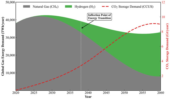
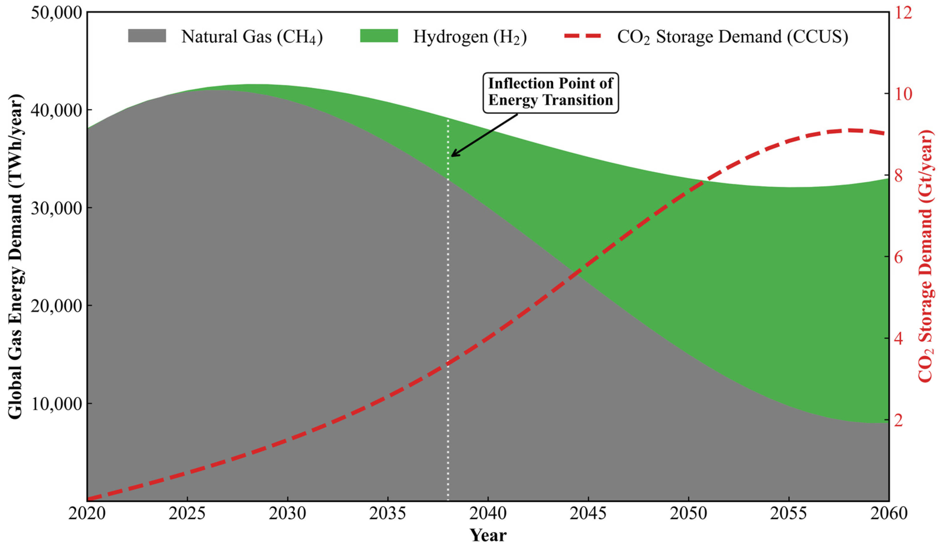
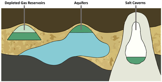
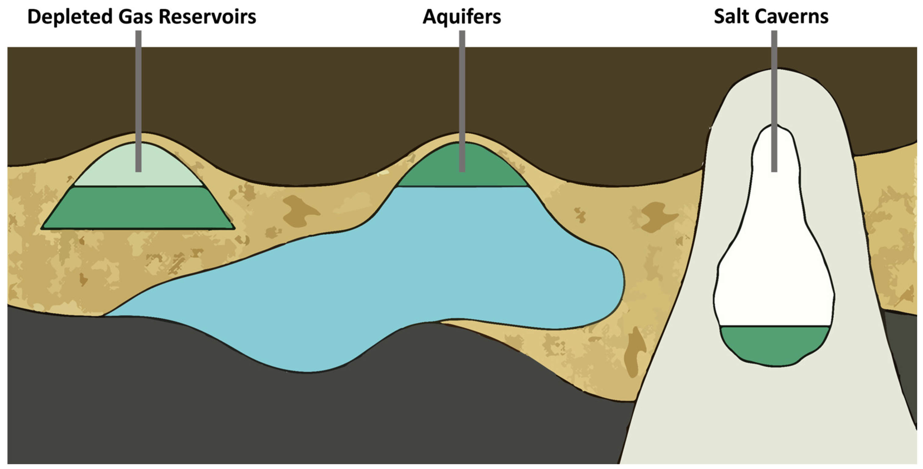
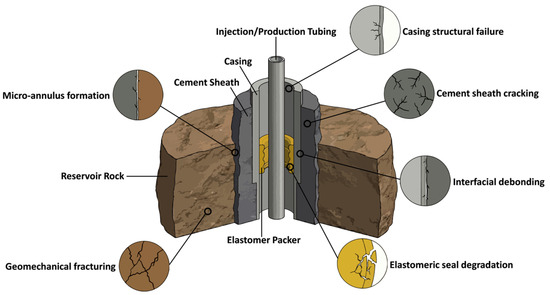
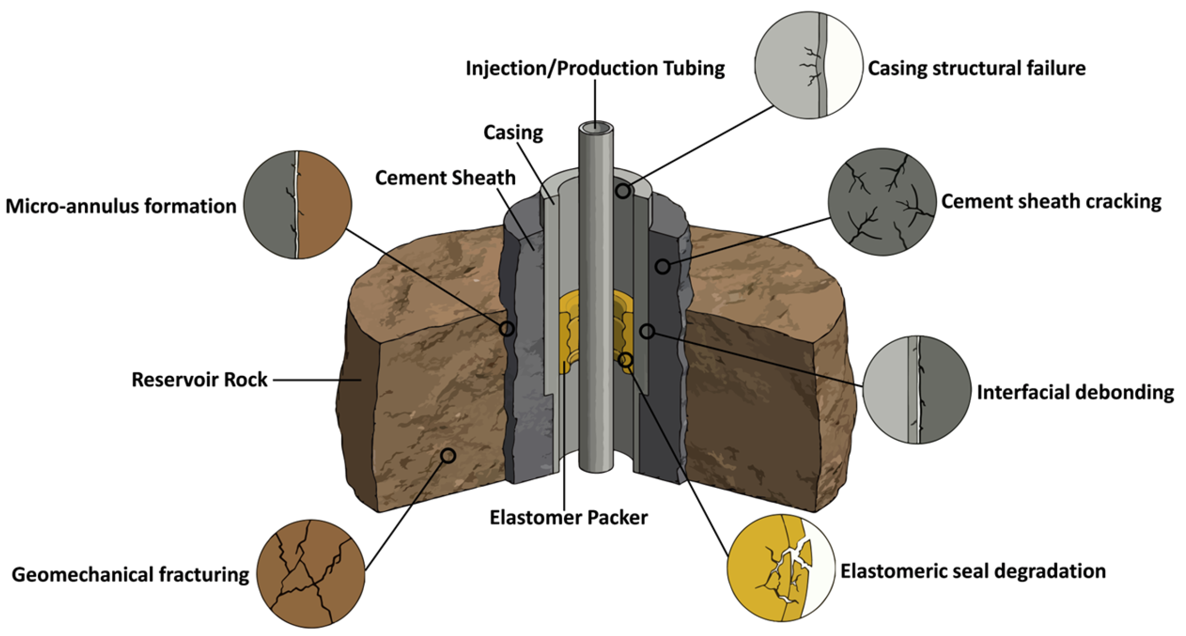
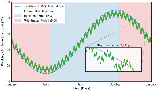
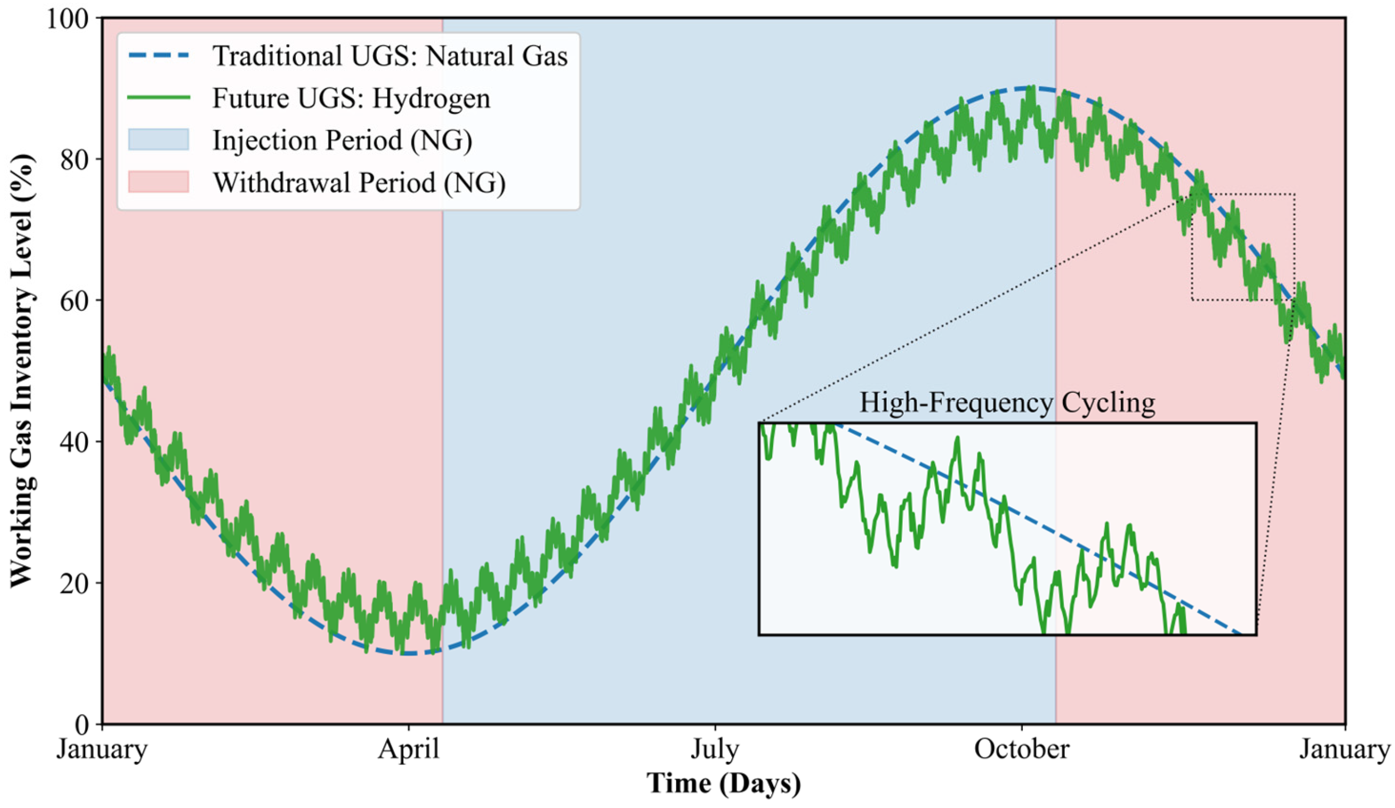
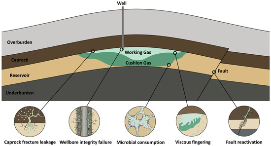
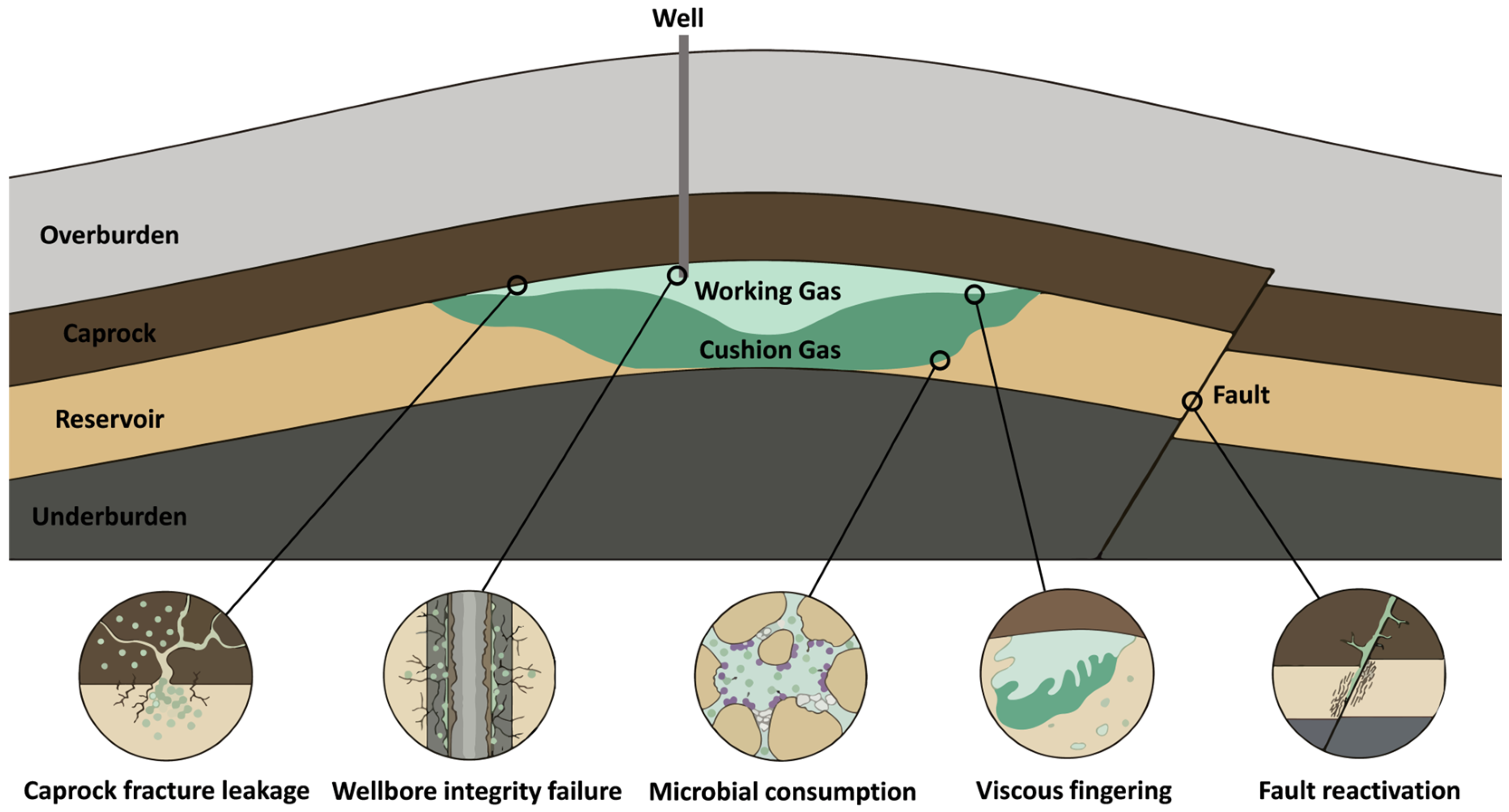
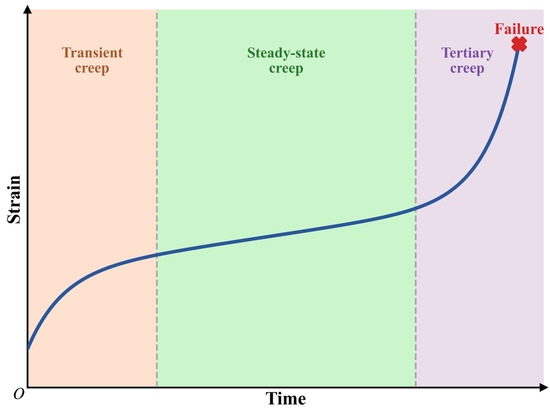
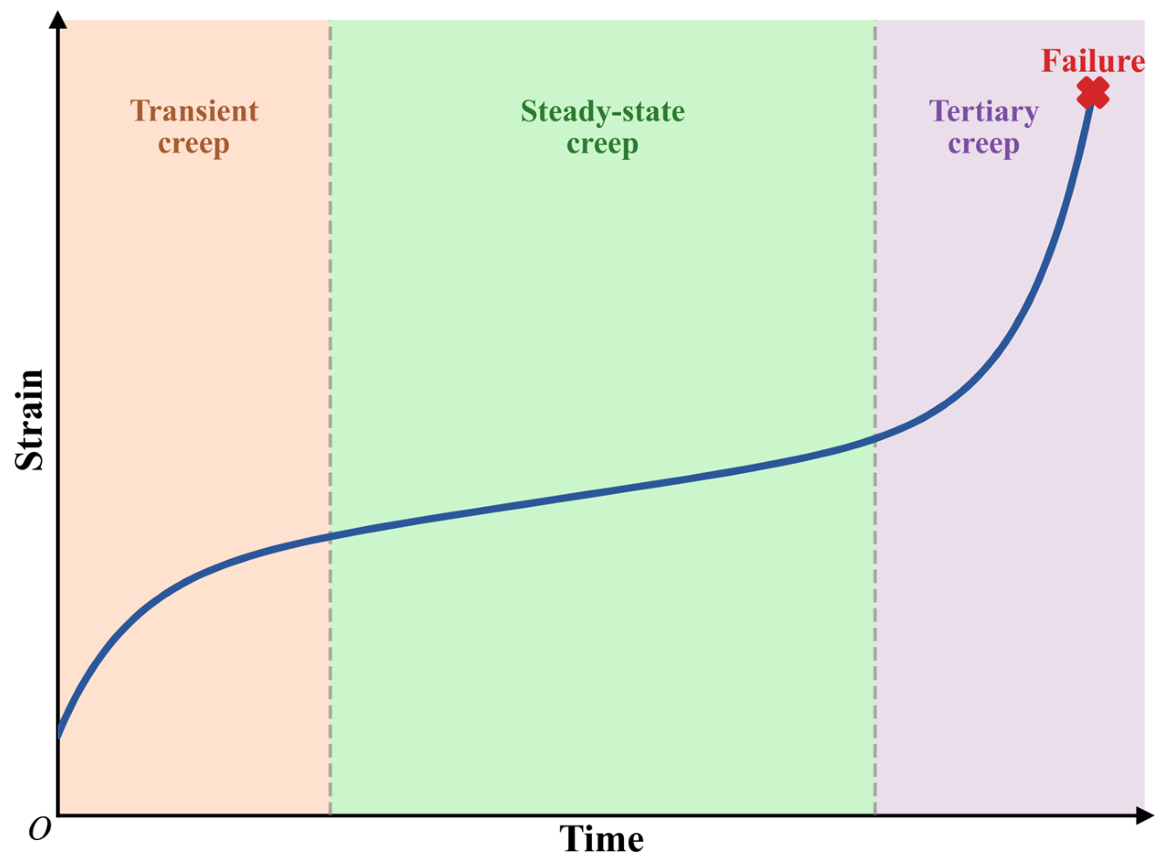
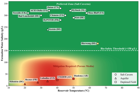
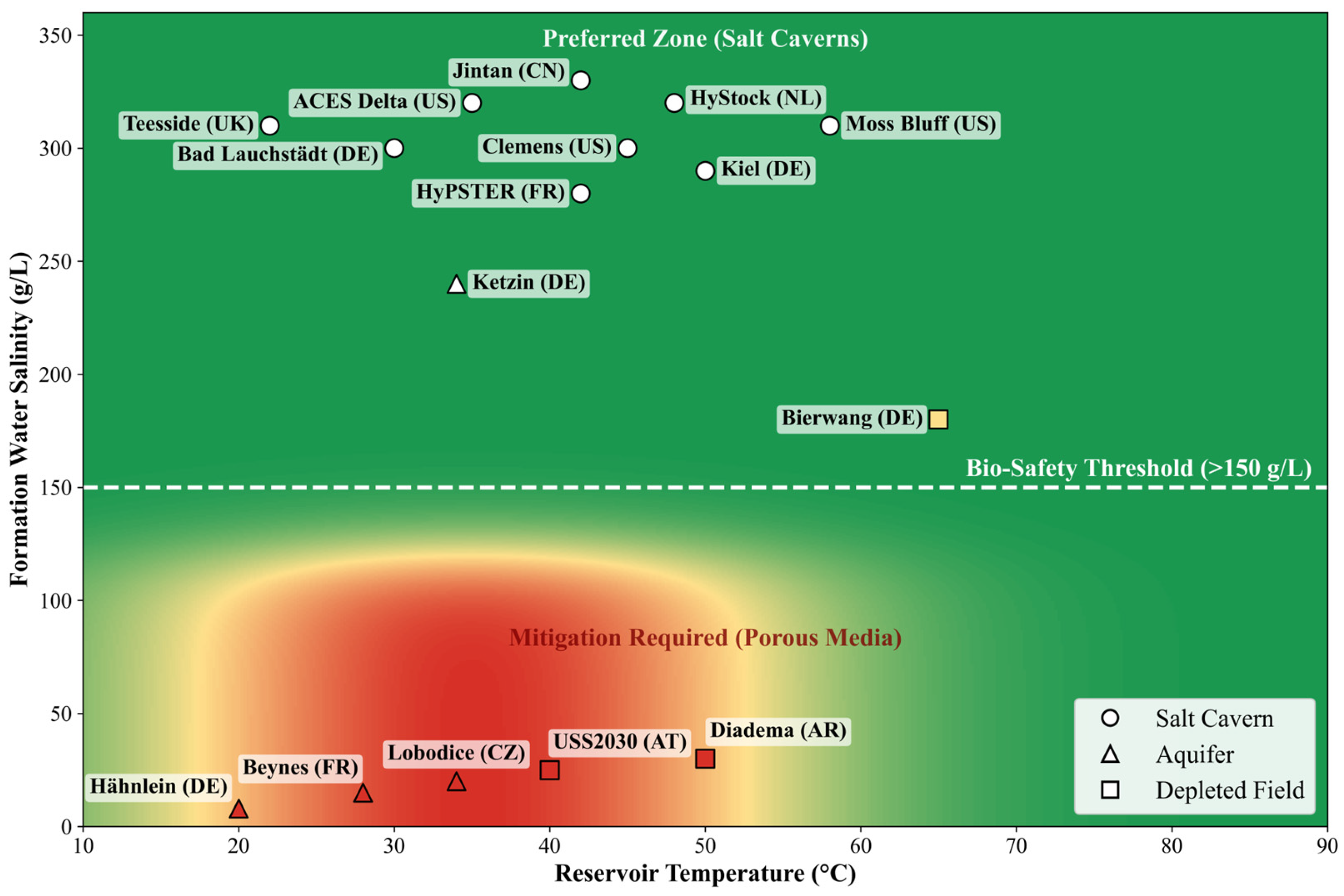
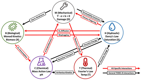
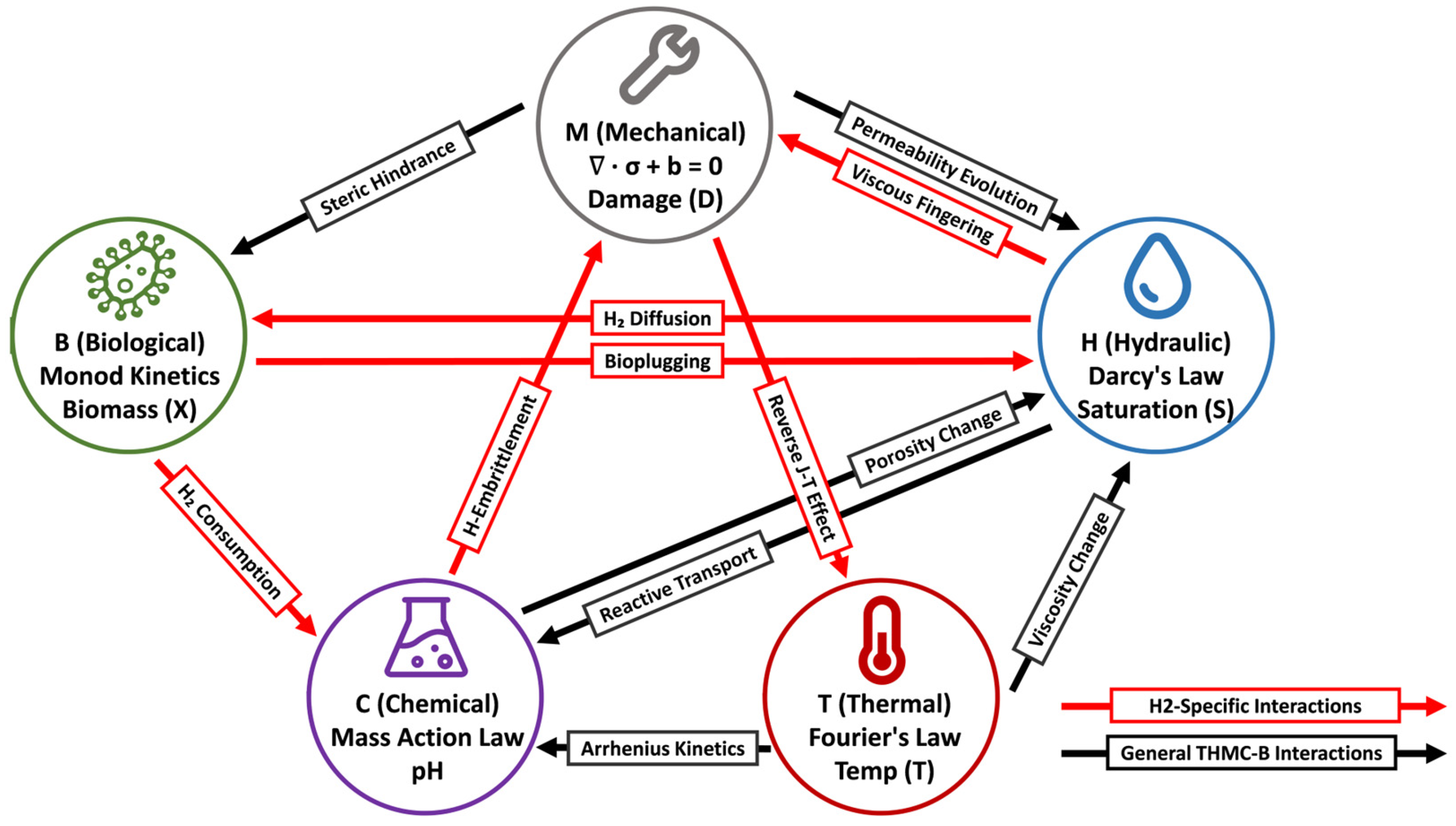
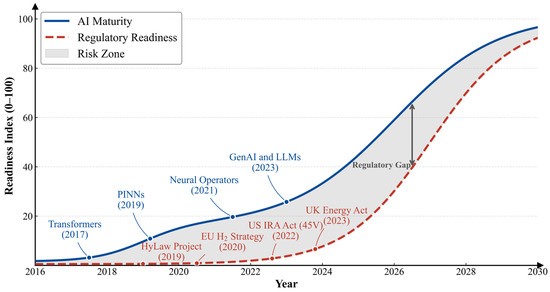
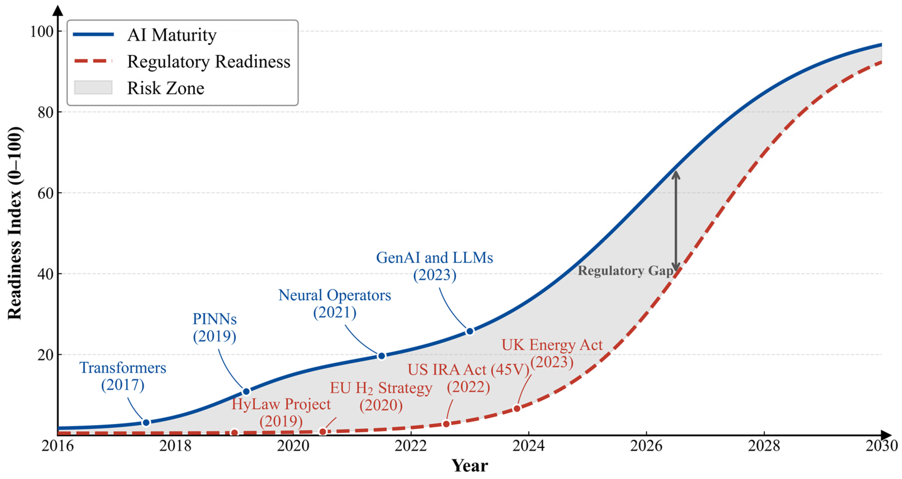

Disclaimer/Publisher’s Note: The statements, opinions and data contained in all publications are solely those of the individual author(s) and contributor(s) and not of MDPI and/or the editor(s). MDPI and/or the editor(s) disclaim responsibility for any injury to people or property resulting from any ideas, methods, instructions or products referred to in the content. |
© 2026 by the authors. Licensee MDPI, Basel, Switzerland. This article is an open access article distributed under the terms and conditions of the Creative Commons Attribution (CC BY) license.