


Abstract
Multiphase permanent magnet synchronous motors (PMSMs) have been widely used in renewable energy, electric vehicle, and aviation applications. Model predictive control has emerged as a mainstream technique for multiphase drives, although conventional implementations suffer from the complexity of weighting factor tuning and excessive computational burden. This paper proposes a dimensionless multi-objective model predictive current control (MPCC) strategy for six-phase PMSM drives that operate without conventional weighting factors. Instead of penalizing harmonic subspace x-y currents through weighted cost terms, the proposed method pre-filters the 64 candidate voltage vectors to a selective set of 12 vectors whose α-β and x-y plane projections are inherently balanced, thereby constraining harmonic excitation at the source. A dimensionless multi-objective cost function is subsequently formulated, integrating current tracking, switching reduction, torque ripple suppression, and voltage/current constraints without additional weighting factors. The proposed strategy is evaluated under startup, steady-state, disturbance, and parameter sensitivity scenarios, with comparative analysis against conventional MPCC. Simulation results demonstrate that the phase current total harmonic distortion is reduced from 29.64% to 6.00%. The q-axis current settling time is reduced from 0.12 s to 0.025 s and the startup overshoot is reduced from 22 A to 11 A. The x-y subspace current ripple and average switching frequency are also reduced.
1. Introduction
Due to the growing use of electric drive systems in industrial automation, electric vehicle (EV), and renewable energy conversion systems, these systems have attracted considerable attention [1,2,3]. This ubiquity has intensified research into pushing the boundaries of torque density, efficiency, and operational reliability [4]. Achieving such improvement demands the simultaneous optimization of the three interconnected subsystems: the power converter that shapes the power supply, the electromechanical actuator that converts energy to motion, and the control algorithm that orchestrates their interaction [2].
There are two complementary approaches for improving the performance of electric drives. One is the hardware-oriented method, which pursues novel machine geometries and advanced converter topologies [5]. The other is the software-oriented method, which develops new control algorithms to extract the maximal capability from existing drive systems [3,6]. Great efficiency, great power density, small harmonic distortion, and reliable operation under challenging conditions are increasingly required for modern electric drive systems [2,3,7,8]. Multiphase permanent magnet synchronous motor (PMSM) drives have gained particular interest, because their additional degrees of freedom enable higher power density without increasing per-phase current stress, while the redundant phases provide intrinsic fault tolerance [7,9]. Multiphase systems, however, require more complicated control architectures than their three-phase counterparts [8,10]. Traditional multiphase PMSM drives use a two-level (2L) voltage-source inverter (VSI) for their simplicity [4], whereas multi-level (ML) alternatives exploit additional voltage vectors to reduce voltage/current harmonics at moderate switching frequencies [11,12,13].
Control strategy can determine whether these hardware capabilities translate into real-world performance. Field-oriented control (FOC) remains the industrial baseline, offering decoupled torque and flux regulation but requiring precise parameter knowledge and fine tuning [14]. Direct torque control (DTC) provides faster dynamic response by directly controlling stator flux and torque, though at the cost of variable switching frequency and higher current ripple [15,16]. Model predictive control (MPC) has emerged as a compelling candidate because it explicitly handles multivariable constraints and non-linearities within a single optimization framework, whose properties align naturally with multiphase drive complexity [17]. The multiphase winding configuration introduces additional subspaces in the current space vectors, and harmonic components in the stator currents can adversely affect the current quality and torque performance of multiphase PMSM drives [18,19,20]. Recently, MPC has been successfully applied to multiphase motor drive control [18,21]. However, the large number of inverter voltage vectors and inherent redundancy in multiphase systems cause significant increase in the computational complexity with phase count, necessitating appropriate simplifications for practical applications. Among various MPC schemes, deadbeat MPC (DB-MPC) and finite control set MPC (FCS-MPC) remain the most prevalent [18]. The effective FCS-MPC design exploits the inverter’s discrete nature by evaluating a predefined cost function to select the optimal switching states from a finite set for the upcoming sampling interval within a prediction horizon [22]. Its structure resembles conventional DTC, offering excellent dynamic response by direct inverter switching state manipulation without modulation. Thus, switches can be set to the ideal state directly [21]. This method is versatile and intuitive, accommodating multiple-input multiple-output systems while incorporating nonlinear constraints within a transparent cost-function-based control framework.
Despite its conceptual appeal, FCS-MPC faces practical difficulties when scaled to six-phase systems. The inverter’s six-legs generate 64 switching states, and evaluating all candidates during each sampling period imposes a heavy computational load. A more subtle but equally critical issue concerns the cost-function design. Recent research has therefore focused on simplifying cost functions without weighting factors [19], creating virtual voltage vectors (VVV) to reduce complexity, and enhancing steady-state performance for multiphase PMSMs [20,23]. Serra et al. eliminated weighting factors by reformulating the control problem around a deadbeat structure [24], though this restricts the solution space and may sacrifice robustness. Luo and Liu reduced dimensionality by projecting the cost function onto a lower-dimensional subspace [25], yet their method still required offline calibration. Additionally, VVV-based methods have demonstrated effective harmonic suppression in the x-y subspace while maintaining moderate switching frequencies [16,26]. However, these methods either require complex offline VVV synthesis or involve intricate coordinate transformations. The main contributions of this paper are as follows:
- A dimensionless multi-objective MPCC strategy that operates without conventional weighting factors is proposed. By introducing a selective voltage vector set that reduces the candidate vectors from 64 to 12, the proposed method eliminates the tedious trial-and-error tuning of weighting factors inherent in conventional MPCC, while avoiding the complex offline pre-calculation required by virtual voltage vector methods. Specifically, no weighting coefficient is required to balance the fundamental current-tracking objective against x-y harmonic suppression, since harmonic suppression is achieved structurally through vector preselection.
- Inherent harmonic subspace current suppression is achieved at the source. The selected voltage vectors possess balanced projections in both the α-β fundamental and x-y harmonic planes, thereby constraining harmonic excitation without explicit weighted cost terms for x-y currents.
- A dimensionless multi-objective cost function is formulated. Multiple practical constraints, including current tracking, switching reduction, torque ripple suppression, and voltage/current limits, are integrated into a unified framework with all terms individually normalized, so that no weighting factors are required to balance the multiple objectives.
In EV traction applications, where efficiency directly determines driving range and thermal limits constrain continuous output power, suppressing x-y harmonic currents is particularly valuable, as these currents produce additional copper losses without contributing to torque production. The proposed method thereby has the potential to benefit EV motor controllers, since it eliminates weighting factor tuning over wide operating ranges and reduces the online computational burden from 64 to 12 cost-function evaluations per sampling period.
The remainder of this paper is organized as follows. Section 2 develops the six-phase PMSM model and characterizes the inverter voltage vector distribution across α-β and x-y subspaces. Section 3 reviews the conventional MPCC and identifies its limitations. Section 4 presents the proposed MPCC strategy, including the selective voltage vector set design, the weighting-factor-free cost function, and the integrated multi-constraint handling mechanism. Section 5 provides comprehensive simulation results and comparative analyses. Section 6 concludes the paper and suggests directions for future research.
2. Modeling of the Six-Phase PMSM Drive
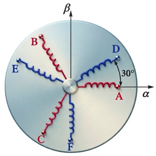
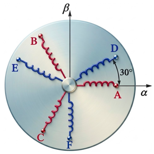
Figure 1 demonstrates the winding configuration of a six-phase PMSM drive system. The selected six-phase PMSM involves two star-shaped three-phase windings (ABC and DEF) with a spatial phase difference of 30° [27,28].
Figure 1.
Winding configuration of the six-phase PMSM drive system.
The vector space decoupling (VSD) method transforms the variables. The VSD transformation separates the six-phase machine variables into mutually orthogonal subspaces, aiding in separating the fundamental and harmonic components for independent analysis and control. The stationary variables of the considered asymmetrical six-phase PMSM can be expressed in the α-β, x-y, and zero-sequence o1-o2 subspaces. The fundamental components of torque and flux generation lie in the α-β subspace, whilst secondary harmonic components are found in the x-y subspace and are not directly involved in the fundamental electromagnetic torque. The two zero-sequence components related to the two three-phase winding groups are in the o1-o2 subspace. In the considered topology, the winding neutrals are isolated, and the zero-sequence currents are limited to zero. The stationary α-β and x-y components are also converted into the rotating d1-q1 and d2-q2 reference frames, respectively, with the electrical rotor at position θ, for control purposes. Thus, the full transformation to the rotating reference frames is:
The VSD transformation matrix that maps the six-phase stationary variables to the rotating d-q reference frames is:
where is the rotor position in the electrical angle.
For the complete VSD transformation matrix in Equation (2), the first two rows correspond to the α-β fundamental subspace (d1-q1), the third and fourth rows to the x-y harmonic subspace (d2-q2), and the last two rows to the zero-sequence components (o1-o2). For the dual three-phase winding configuration with isolated neutrals, the zero-sequence components are inherently zero and thus uncontrollable. Consequently, the predictive model in Section 3 considers only the four controllable variables corresponding to the α-β and x-y subspaces after the Park transformation.
2.1. Mathematical Models
The original six-dimensional coordinate system’s voltage, flux, and torque equations can be mapped to the triple d-q coordinate system by multiplying both sides by T3dq [29,30]. By abridging and omitting the higher-order harmonic inductance components, the voltage equation in the triple d-q coordinate system can be articulated as:
where and () are the stator voltage components of the -th d and q axes, respectively; and () are the stator current components of the d and q axes, respectively; and are the inductance of the d and q axes, respectively; is the stator resistance; is the electrical angular velocity; is the magnetic flux linkage generated by permanent magnets.
The flux linkage equations in the three-phase d-q rotating coordinate system are:
where and () are the flux components of the d and q axes, respectively.
Since the permanent magnet (PM) flux rotates synchronously with the fundamental reference frame and is orthogonal to both the harmonic and zero-sequence subspaces, the PM flux linkage appears only in the d1-q1 equations, i.e., Equations (4) and (9), and does not enter the d2-q2 or d3-q3 equations. As listed in Table 1, the VSD representation transforms the predictive variables into d1-q1 → α-β and d2-q2 → x-y, and omits the zero-sequence components due to the isolated-neutral configuration.
Table 1.
Mapping between the triple d-q and VSD subspaces.
It can be seen that the total output torque is the sum of the torques produced by three groups of two rectangular windings [31,32]. Therefore, the six-phase motor can be considered three independent groups of rectangular two-phase windings. When the six-phase PMSM is designed as a surface-mounted motor, , the electromagnetic torque is produced exclusively by the α-β fundamental subspace. According to the VSD transformation, the torque contribution from the x-y harmonic subspace is negligible under balanced conditions. Therefore, the electromagnetic torque can be expressed as:
where is the number of pole pairs.
The factor 3/2 in Equation (15) arises from the power-invariant VSD transformation for six-phase systems. Note that and correspond to harmonic subspaces and do not contribute to average torque production under ideal conditions.
2.2. Basic Space Voltage Vectors
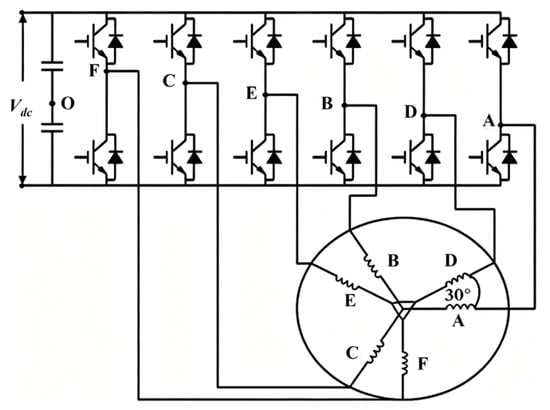
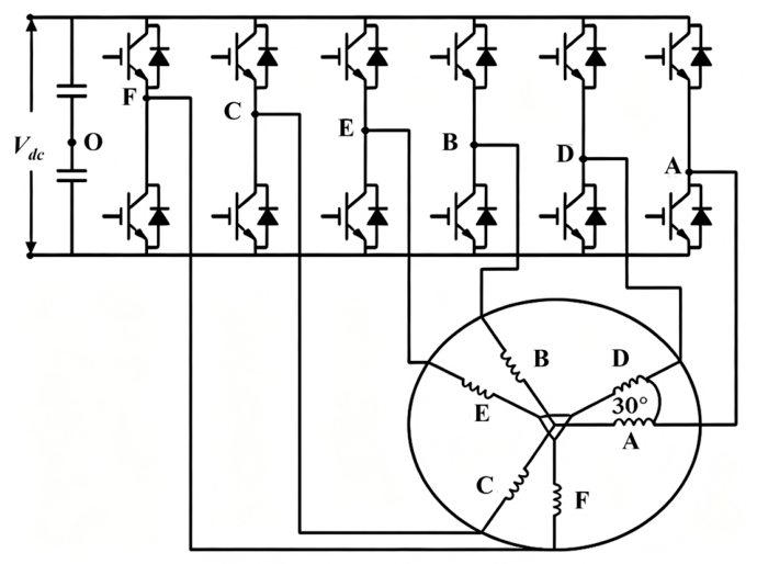
A two-level six-phase VSI often drives the six-phase PMSM. Figure 2 shows the two-level six-phase VSI topology. As displayed in Figure 2, the six-phase VSI comprises six bridge arms, each equipped with an upper and lower switching device. Each device has two binary states (1 and 0, representing on and off), resulting in 26 = 64 switching states [33]. Assuming a zero-voltage component in the o1-o2 zero-sequence subspace, the corresponding voltage vectors in the α-β fundamental plane and x-y harmonic plane can be calculated for each switching state, which are expressed as:
where is the voltage vector of the α-β fundamental plane, is the voltage vector of the x-y harmonic plane, is the DC-link voltage; represents the state of the six bridge arms in the VSI, corresponds to the upper bridge arm being open, while corresponds to the lower bridge arm being open, and is the imaginary unit.
Figure 2.
Schematic of the two-level six-phase VSI topology. “O” is the neutral point of the DC link, “A, B, C, D, E, F” represent one of the six bridge arms.
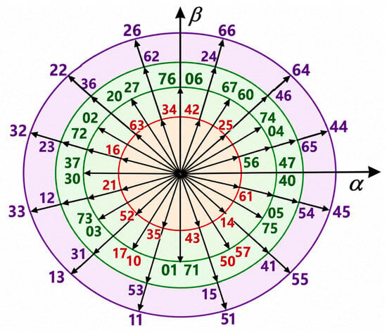
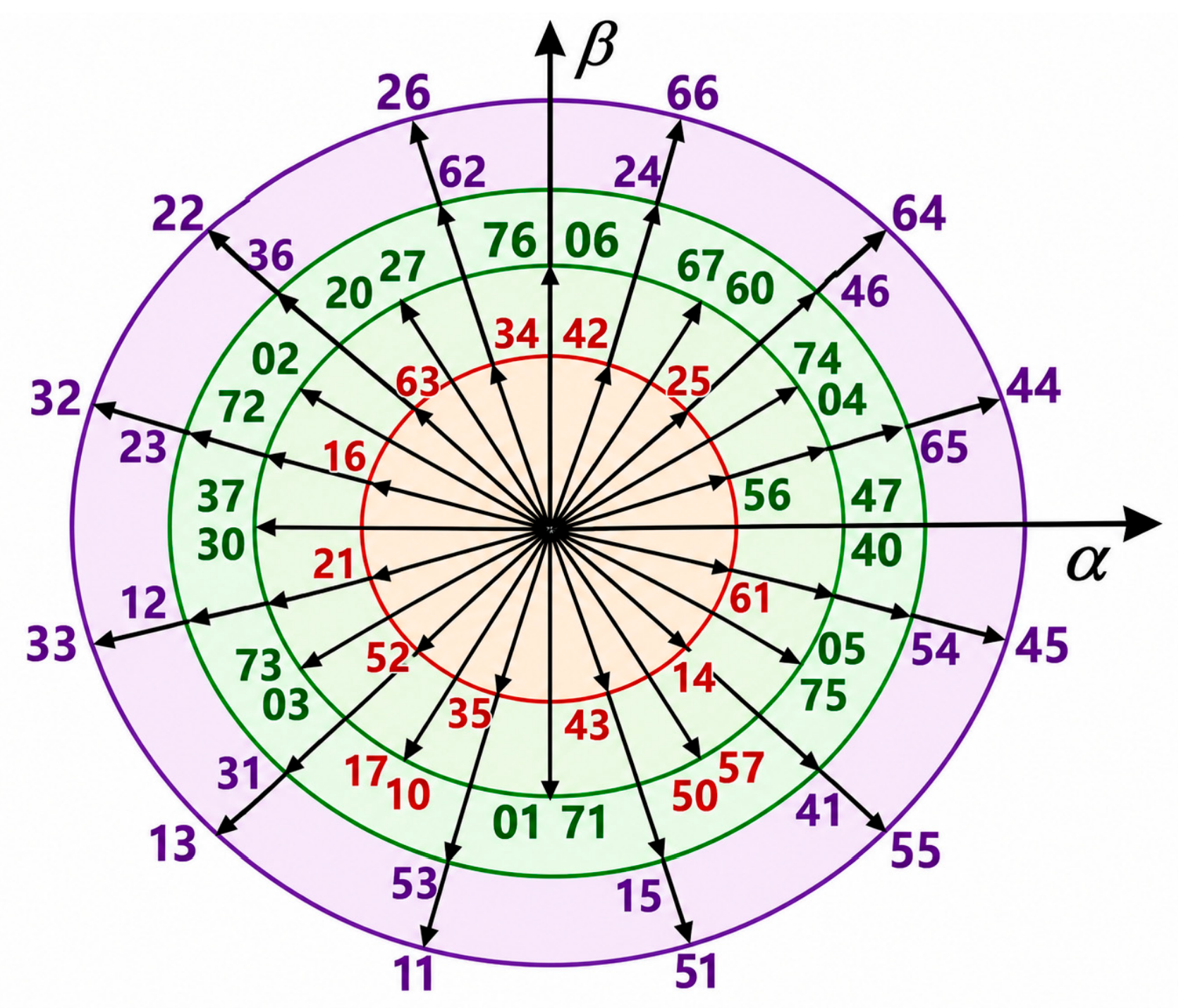
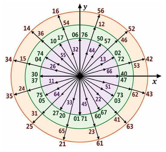
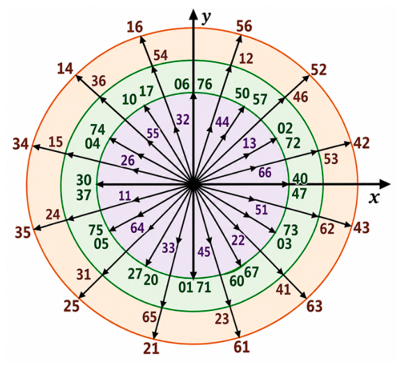
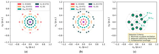
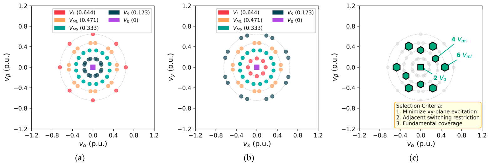
The voltage vector set displayed in Figure 3 and Figure 4 can be derived. As illustrated in Figure 3 and Figure 4, the six-phase PMSM voltage vector set comprises 64 basic voltage vectors, including 60 nonzero voltage vectors and 4 zero-voltage vectors (00, 07, 77, 70). These vectors are defined by octal coding, where each code corresponds to the switching state of bridge arms A through F in the six-phase VSI [34,35]. For example, voltage vector 64 indicates that the upper bridge arms of phases A, B, D, and the lower bridge arms of phases C, E, F are conducting (binary 110100). The basic voltage vector can be classified into five categories based on amplitude: large (), medium–large (), medium–small (), small (), and zero (). Among them, the large, medium–large, and small voltage vectors are synthesized from the medium and small voltage vectors. At the same time, the amplitudes of these four basic voltage vectors in different planes are presented in Table 2. As displayed in Table 2, the vectors are distributed in the α-β fundamental plane and x-y harmonic plane with a one-to-one correspondence between planes [36,37]. In the α-β fundamental plane, large voltage vectors have the maximum amplitude, but the minimum amplitude in the x-y plane. Conversely, small voltage vectors have minimum amplitude in the α-β plane but maximum in the x-y plane. The amplitudes of medium–large and medium–small voltage vectors remain constant across both planes.
Figure 3.
Distribution of the 64 basic voltage vectors in the α-β plane.
Figure 4.
Distribution of the 64 basic voltage vectors in the x-y plane.
Table 2.
Amplitudes of the basic voltage vectors in the α-β and x-y planes.
3. Conventional MPCC Strategy
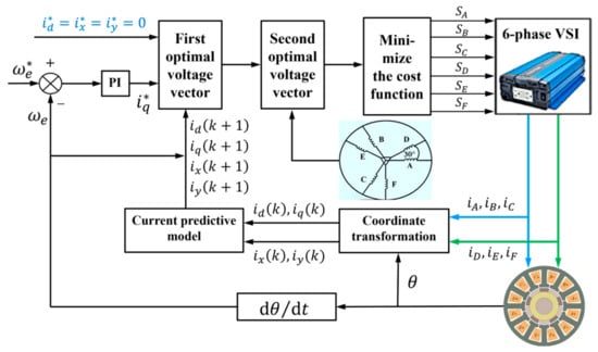
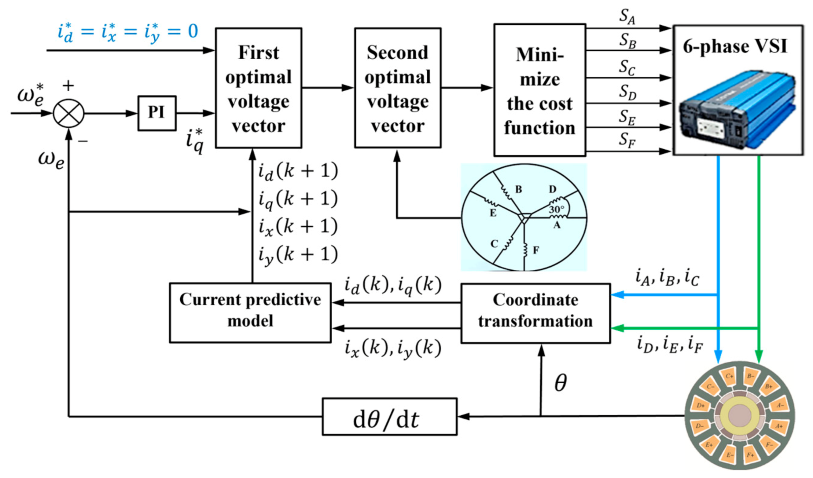
Figure 5 displays a block diagram of the conventional MPCC method. The control system comprises several functional units: a signal acquisition unit for sampling current and rotor position, a VSD and Park transformation unit for converting stator currents, a current prediction model for d-q axis current forecasting, a speed-loop PI controller for generating reference currents, and a cost-function unit for evaluating the optimal voltage vector [38,39]. It also includes a vector control set unit and a six-phase VSI unit.
Figure 5.
Block diagram of conventional model predictive current control method.
Throughout this paper, the motor convention is adopted: positive stator current flows into the machine, the d-axis of each rotating reference frame is aligned with the corresponding fundamental or harmonic flux axis, and the q-axis leads the d-axis by 90° in the direction of rotation. Accordingly, the PM back electromotive force (EMF) term enters the q-axis voltage equation with a positive sign, and appears with a negative sign after rearranging the current derivative in the discrete prediction model.
The forward Euler scheme is often used to construct this prediction model because it is a simple and effective discretization method [40,41]. Applying this method estimates the system’s future behavior, providing the necessary input for MPC and ensuring the control strategy achieves desired optimization objectives [42,43]. The voltage and flux matrix in the rotating frame are transformed to construct the predictive current model for a six-phase PMSM [44,45]. As established in Section 2, only the α-β and x-y subspace currents are controllable, since the zero-sequence components vanish due to the isolated neutral configuration. According to Equations (9)–(14), the voltage equations in the synchronous rotating coordinate system for the controllable subspaces are:
The PM flux linkage is included in the fundamental d-q subspace because the rotor’s PM flux aligns with the fundamental rotating reference frame. Hence, the back-EMF term, due to speed, appears in the q-axis equation. The x-y subspace, on the other hand, includes harmonic components orthogonal to the fundamental PM flux, and, in Equations (20) and (21), the PM flux and speed-coupling terms are not included. After deriving the state equation for the stator current, it becomes imperative to discretize Equations (18)–(21) utilizing the Euler method approximation. The precise formulation of the Euler approximation is:
where is the sampling period; is the number of time steps; and are the estimated current values of the d- and q-axis at the time step , respectively; and are the estimated current values of the x- and y-axis the time step , respectively; and are the estimated current values of the d- and q-axis at the time step , respectively; and are the estimated current values of the x- and y-axis the time step , respectively.
Based on the VSD transformation presented in Section 2, the six-phase currents are decoupled into the d-q fundamental subspace and the x-y harmonic subspace. The zero-sequence components are omitted due to the isolated neutral configuration. Substituting the Euler approximation Equations (22) and (23) into the voltage Equations (18)–(21), the predicted current model of the six-phase surface-mounted PMSM in the synchronous rotating coordinate system is obtained as:
In the FCS-MPC approach, the cost function serves as the primary criterion for evaluating the effect of the voltage vector. The cost function is constructed to meet the specific requirements of the control task and can comprehensively consider multiple motor performance parameters, such as speed, torque, flux, and current [46]. Among them, when the current is used as the control target, the objective function is defined as:
where , , , and denote the reference currents of the d-, q-, x-, and y-axis; and are the weight coefficients, they are used to balance the performance between fundamental current tracking and harmonic suppression.
In conventional MPCC, the weighting factors are indispensable for balancing the competing objectives within the cost function, as their absence results in an imbalanced optimization landscape and degraded control performance. These factors are typically determined empirically through iterative tuning, where the adjustment is guided by the trade-off among current-tracking accuracy, harmonic suppression efficacy, and overall system stability; their optimal values are inherently dependent on operating conditions. To ensure an equitable comparison, the conventional MPCC was implemented with optimally tuned weighting factors, whereas the proposed strategy operates without them.
4. Proposed MPCC Strategy
4.1. Selective Voltage Vector Set Design
This study proposes a selective voltage vector strategy that reduces the number of candidate voltage vectors from 64 to 12, thereby suppressing harmonic components while maintaining computational efficiency. The selection criteria are as follows:
- Fundamental subspace coverage: only voltage vectors with significant α-β plane projection are retained, ensuring sufficient torque and flux control capability;
- Harmonic subspace minimization: vectors with large x-y plane amplitudes (i.e., the small vectors) are excluded, as they excite harmonic currents, whereas the two zero vectors are retained as zero-voltage candidates;
- Adjacent vector restriction: only vectors adjacent to the previous switching state are considered, reducing switching transitions and associated losses.
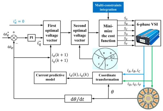
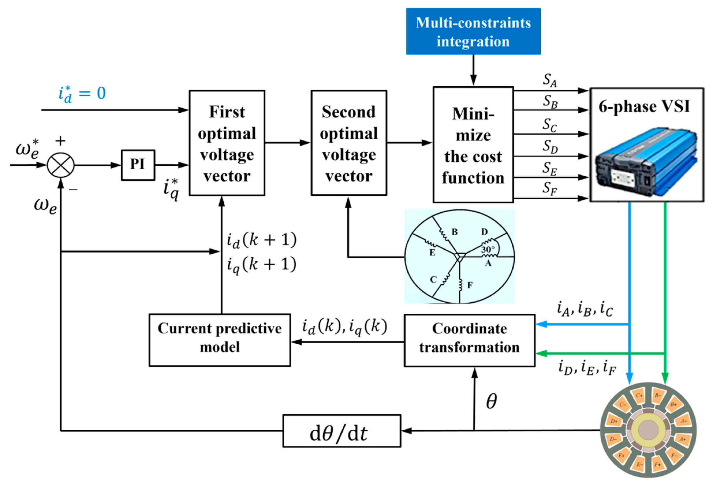
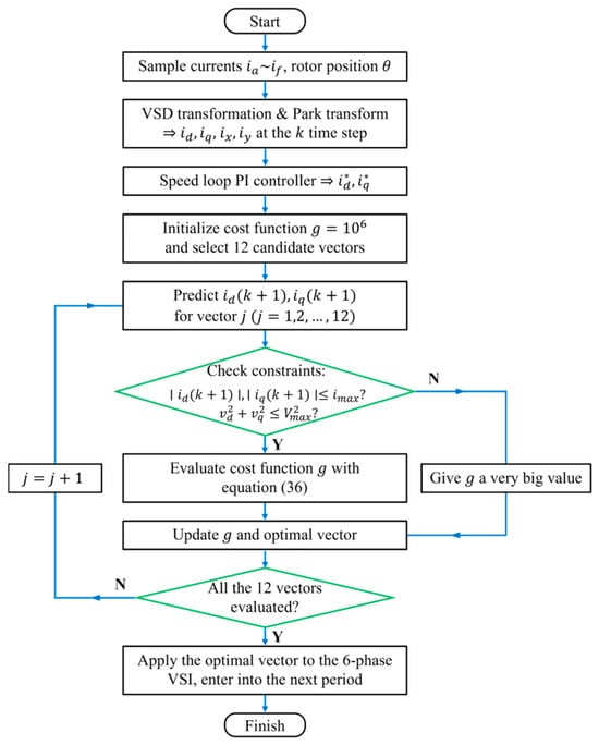
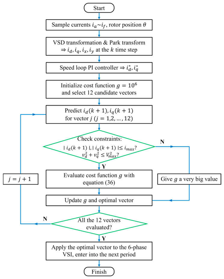
Quantitatively, a basic voltage vector is admitted into the candidate set only when all of the following conditions hold: (i) its α-β amplitude is no less than , guaranteeing sufficient voltage margin for torque and flux control; (ii) its x-y amplitude does not exceed its α-β amplitude, so that the harmonic excitation per unit fundamental voltage is bounded; and (iii) transitions between successively applied candidate vectors require no more than two bridge-arm commutations, limiting the switching effort. Although the large vectors exhibit the highest α-β projection () and a relatively small x-y projection (), they are excluded by condition (iii): switching to a state from its adjacent candidate states requires the simultaneous commutation of three bridge arms, which increases switching losses and common-mode voltage steps; moreover, their larger volt-second area aggravates the current ripple at low modulation indices. It should be noted that condition (iii) is an offline design criterion used to construct the candidate set, rather than a constraint checked during online optimization. At each sampling instant, the switching effort is penalized through the switching term in the designed cost function, so that candidates requiring fewer commutations are naturally preferred by the online optimization. The remaining 6 medium–large vectors , 4 medium–small vectors , and 2 zero vectors satisfy all three conditions and constitute the 12-vector candidate set listed in Table 3. Figure 6 shows the proposed MPCC strategy block diagram, Figure 7 illustrates workflow of the proposed control algorithm, and Figure 8 depicts voltage vector selections for the conventional and proposed MPCC.
Table 3.
Selected voltage vectors for the proposed MPCC.
Figure 6.
Block diagram of the proposed model predictive current control strategy.
Figure 7.
Flowchart of the proposed MPCC strategy.
Figure 8.
Voltage vector selections for the conventional and proposed MPCC: (a) The α-β plane with full 64 vectors. (b) The x-y plane with full 64 vectors. (c) Selected 12 vectors in α-β plane. Green hexagons denote the selected vectors, while gray dots represent the unselected ones.
4.2. Weighting-Factor-Free Cost Function
By restricting the candidate voltage vectors to those with minimal x-y plane excitation (Table 2), the harmonic subspace currents are inherently constrained without explicit regulation. Consequently, the x-y current terms can be eliminated from the cost function, achieving true weighting-factor-free operation:
The physical interpretation of Equation (28) is: the selected voltage vectors possess balanced α-β and x-y plane amplitudes (for and ) or zero amplitude in both planes (for ), thereby naturally limiting harmonic current injection. This differs fundamentally from conventional approaches that actively penalize x-y currents through weighted cost terms.
4.3. Multi-Constraint Integration
Beyond current tracking, the proposed MPCC integrates multiple practical constraints into a unified multi-objective cost function, ensuring balanced multi-objective optimization without additional weighting factors.
In Equation (29), is a nonlinear equation that limits the stator current amplitude, specifically expressed as in Equation (30), where is the maximum allowable amplitude of the stator current when the sampling time is short. This control strategy results in reduced switching transitions, which is achieved by incorporating a restriction on state changes in the control procedure while utilizing a single state variation for every sample:
where is a large positive penalty coefficient, e.g., .
This soft constraint in Equation (30) avoids numerical discontinuities while effectively enforcing current limits. Furthermore, one of the most crucial changes to the six-phase PMSM-proposed MPCC is the voltage limit constraint, which stops the controller from selecting voltage vectors that exceed the inverter voltage limit.
This helps reduce saturation and improves voltage utilization. The inverter voltage constraint is defined in the α-β reference frame as:
where and are the d- and q-axis stator voltages, respectively; is the maximum inverter voltage magnitude.
For a two-level VSI with space vector modulation:
The voltage limit is implemented as a soft constraint to ensure optimization continuity:
where is a large positive voltage penalty coefficient, e.g., .
A torque ripple reduction term is added to the objective function of the six-phase PMSM to improve dynamic performance and torque smoothness, with potential benefits for vibration and acoustic noise reduction. The simplest torque-tracking penalty is:
where is the reference electromagnetic torque, is the predicted torque at the time step , and is the maximum electromagnetic torque.
The complete cost function for the proposed MPCC is:
where is the switching-weight coefficient, and is a dimensionless count bounded by the maximum of six commutations per sampling period.
Equation (36) is the form implemented in the simulations, where the raw squared current errors are used directly; a dimensionless counterpart can be obtained by normalizing each objective term with its nominal value, so that every objective term has a comparable numerical scale. The proposed weighting-factor-free formulation is not based on the conventional weighting factors that balance the fundamental current-tracking goal with the harmonic subspace suppression goal. Instead, the structural approach is used for harmonic suppression, using only a subset of 12 vectors as candidates. Coefficients and are kept only as large penalty coefficients for current and voltage constraints. Therefore, these coefficients are not to be understood as conventional weighting factors for objectivity. Specifically, the current-tracking terms are normalized by the square of the rated stator current, the torque ripple term is normalized by the square of the maximum torque as shown in Equation (35), and the switching term is a dimensionless count bounded by the maximum of six commutations per sampling period, so that all objective terms share a comparable numerical range. The penalty coefficients are selected several orders of magnitude larger than the normalized objective terms ( and ) so that the current and voltage limits act as near-hard constraints; the control performance is insensitive to their exact values as long as they remain sufficiently large. The switching coefficient is set to 0.1 in this work: with at most six commutations per sampling period, one additional commutation adds 0.1 to the cost, comparable to a current-tracking error of about 0.32 A; this provides a satisfactory trade-off between switching frequency reduction and current-tracking accuracy.
4.4. Comparison with the VVV-Based Method
The recent literature has proposed virtual voltage vector (VVV) as an alternative approach to harmonic suppression in multiphase PMSMs. Huang et al. [47] employed 12 virtual voltage vectors from adjacent small vectors, achieving zero x-y plane excitation through offline pre-calculation. Though effective, it requires complex offline VVV tables and restricts dynamic adaptability under parameter variations.
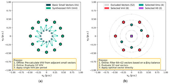
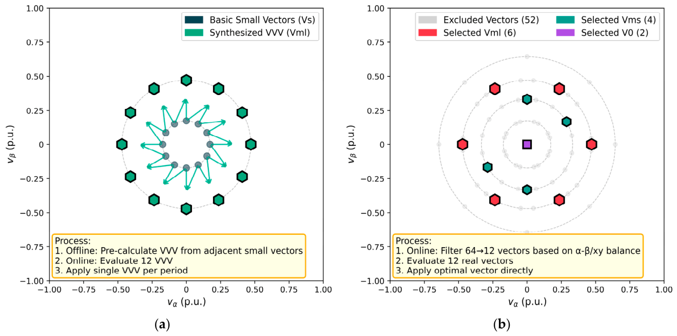
This section compares the proposed direct selection strategy with the VVV-based method of Huang et al. [47], highlighting fundamental differences in implementation and performance. The structural difference between the VVV synthesis and the proposed MPCC is illustrated in Figure 9. In Figure 9a, each VVV is generated by combining two basic small vectors, requiring pre-calculated switching state tables and additional coordinate transformations during implementation. Unlike the VVV method, as shown in Figure 9b, our proposed direct selection strategy filters the 64 candidate vectors to 12 real vectors (6, 4, and 2) selected offline according to their α-β and x-y plane amplitude ratios; this candidate set is fixed for all operating conditions, while the optimal vector is selected online at each sampling instant.
Figure 9.
Structural comparison between the VVV synthesis and the proposed MPCC: (a) The VVV synthesis by Huang [47], 12 virtual vectors (offline). The green arrows represent the synthesis of the basic voltage vectors. (b) The proposed MPCC, direct selection of 12 real vectors (online).
Our proposed direct selection strategy differs primarily in three aspects:
- Reduced offline burden: the VVV synthesis relies on pre-calculated virtual vector tables and duty-ratio synthesis, whereas the proposed method uses a fixed candidate set of 12 real vectors and only evaluates the cost function online, without any offline vector pre-calculation;
- Computational efficiency: the VVV synthesis requires additional coordinate transformations to map virtual vectors to real switching states; the proposed method applies real vectors directly;
- Dynamic response: as will be shown in Section 5, the proposed method achieves faster settling time because it avoids the modulation-stage delay inherent in the VVV implementation.
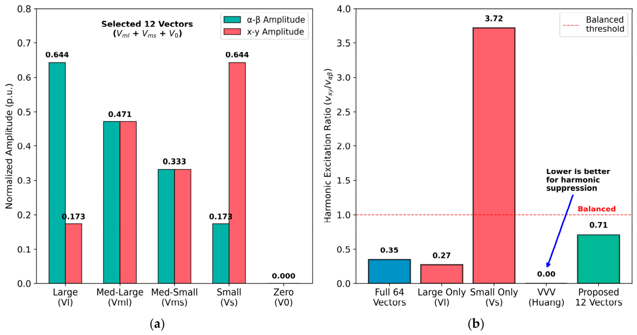
The harmonic excitation ratio is defined as the ratio of the x-y harmonic amplitude to the total magnitude of the voltage vector:
Thus,
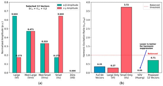
For the selected medium–large vectors, and for the medium–small vectors, , both gave , which is rounded to 0.71 in Figure 10.
Figure 10.
Theoretical analysis of harmonic suppression boundaries: (a) Voltage vector amplitude distribution. (b) Harmonic excitation capability [47].
Figure 10 provides a theoretical analysis of harmonic excitation boundaries, demonstrating that while VVV achieves complete harmonic cancelation (), the proposed method maintains bounded harmonic excitation () with significantly lower implementation complexity. Moreover, since the selected and vectors have equal α-β and x-y amplitudes, their harmonic excitation is bounded by construction, keeping the x-y subspace currents controllable within the tested operating range. It should be noted that Huang et al. [47] provided experimental validation on a 2.5 kW six-phase PMSM prototype, whereas the proposed method in this paper is currently limited to simulation results. This represents a gap that will be addressed in future experimental work.
5. Simulation Results and Discussion
The performance and efficacy of the proposed MPCC described in this paper was assessed using a comprehensive MATLAB/Simulink R2024a simulation model of the six-phase PMSM drive system. The simulation’s environment was created to replicate the motor drive system’s real-world operating conditions, and the outcomes could be accurately compared with both the conventional and proposed motor drive control techniques.
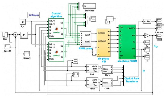
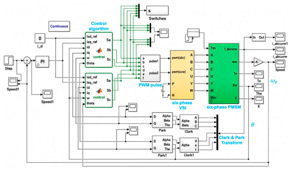
The developed MATLAB/Simulink model in Figure 11 contains a complete six-phase PMSM drive system with the control algorithm, motor model, mechanical dynamics, coordinate transformation, and six-phase inverter. The control structure is responsible for receiving the reference speed and measured motor variables and producing the appropriate switching signals to the two groups of three-phase inverters. The motor model is based on the electrical and mechanical characteristics of the six-phase PMSM, where the stator voltage and current of both sets of three-phases are transformed using the Clarke and Park transformations to the desired α-β and d-q components, respectively. The electromagnetic torque, rotor speed, rotor position, phase currents, and back electromotive force signals are sent to the control system to enable closed-loop control. The inverter stage is a two-stage structure comprising two three-phase voltage-source inverter bridges with a common DC link, producing the six different switching states needed to drive the two groups of three windings in the stator. This integrated configuration can be used to assess the proposed control strategy under various combinations of reference speed and load torque, and to provide the mechanical and electrical variables used to evaluate performance.
Figure 11.
The developed MATLAB/Simulink model for simulation.
This model allows the dynamic and steady-state behavior of the multiphase drive system to be studied under different operating conditions. Here, the proposed control strategy’s transient response performance, torque ripple reduction, harmonic suppression, and current-tracking performance were examined.
For a fair comparison, both the conventional MPCC and the proposed MPCC were evaluated using the same machine model, inverter model, sampling period, speed-loop PI controller, reference and load conditions, and disturbance profiles; only the candidate vector set and the cost-function structure differ between the two controllers. The steady-state and THD comparisons use the conventional MPCC as the baseline, while the VVV-based method of Huang et al. [47] is included in the q-axis ripple and load-disturbance comparisons because it represents the most closely related harmonic suppression approach.
The resilience and reliability of the proposed MPCC algorithm were tested under a variety of operating circumstances, including abrupt load disruptions and steady-state operation. Additionally, the simulation’s motor settings were carefully selected to accurately analyze the system. These include the rotor inertia, pole pairs, DC-link voltage, flux linkage, d-axis and q-axis inductances, and stator resistance. For clarity and convenience, a systematic list of the major motor parameters employed in the simulation is given in Table 4.
Table 4.
Motor parameters used in the simulation.
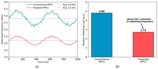
The average switching frequency is a critical performance metric for FCS-MPC. For the conventional MPCC with 64-vector enumeration, the average switching frequency is 4.8 kHz at the rated condition. The proposed MPCC with 12-vector selective strategy achieves an average switching frequency of 3.2 kHz, a 33% reduction in average switching frequency while maintaining superior current quality.
5.1. Computational Complexity Analysis
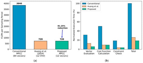
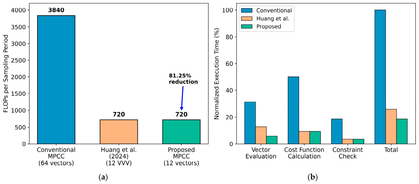
The computational burden of FCS-MPC is dominated by vector evaluation and cost-function calculation. For the conventional MPCC with 64 candidate vectors, each vector requires current predictions of 4 floating point operations (FLOPs), cost evaluation of 8 FLOPs, and constraint checking of 3 FLOPs, totaling approximately 960 FLOPs per sampling period. The proposed method reduces candidate vectors to 12, decreasing the total to 180 FLOPs, i.e., over an 81.25% reduction, as depicted in Figure 12a.
Figure 12.
Comparison of the computational complexity and execution time: (a) Computational complexity. (b) Execution time breakdown [47].
Figure 12 compares the execution time breakdown. Notably, the proposed approach eliminates the x-y current prediction and weighted cost terms, further reducing the computational overhead, as shown in Figure 12b. The VVV method [47] leads to additional overhead for virtual vector synthesis and coordinate transformation, increasing its effective execution time by approximately 15% compared to the proposed direct selection. The 12-vector method enables more efficient memory access patterns, as the vector set can be stored in processor cache rather than requiring main memory lookups for all 64 states.
5.2. Stator Current Waveforms
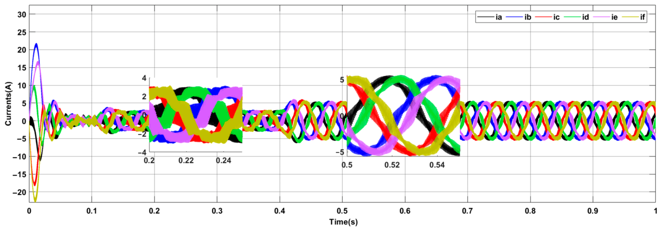
Figure 13 displays the six-phase stator current waveforms recorded under various operating situations using the conventional MPCC approach. At startup , the phase currents reach peak values of approximately +22 A and −21 A during the startup transient. This behavior results from the rapid acceleration at startup and the limited ability of the conventional controller to regulate the transient oscillations. After approximately 0.05 s, the currents gradually converge towards the steady-state operating points, although the harmonic components still cause some ripples and waveform distortions. The current ripple and harmonic distortion during the steady state of operation are shown by the enlargement of both phase currents between 0.2 s and 0.24 s. At , the system experiences a rapid load disturbance that results in another transient reaction with a step increase in the current amplitude of up to almost 5 A.
Figure 13.
Six-phase stator current waveforms with the conventional MPCC method.
The zoomed region between 0.5 s and 0.55 s shows that the current waveforms are extremely oscillatory and then converge to steady-state conditions. Additionally, as is typical of a six-phase PMSM system, the six-phase currents (, , , , , and ) have a balanced phase displacement. However, there is a considerable amount of low-order harmonic content since the waveforms are not sufficiently sinusoidal.
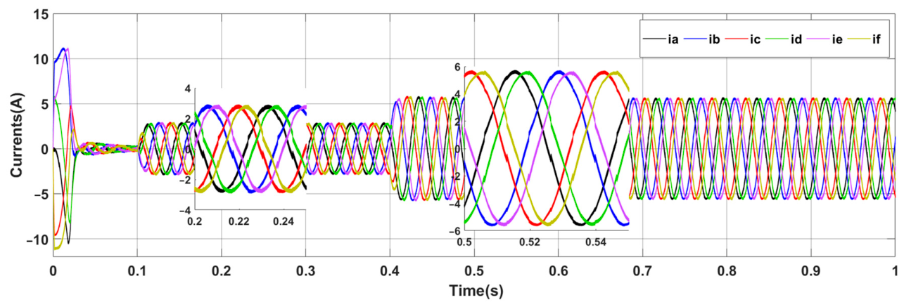
As seen in Figure 14, the six-phase stator current waveforms are obtained using the proposed MPCC. Compared to the conventional controller, the proposed controller produces current waveforms that are smoother and more sinusoidal, and it reduces oscillations and harmonic distortion. The phase currents during startup show transient excursions of about ±11 A, which is much smaller than those in the conventional technique. Since the current settles in at around 0.05 s, the dynamics and transient responsiveness are enhanced. The phase currents retain an essentially sinusoidal form with a smooth and regular change in their amplitude from ~3 A, as shown by the larger region between 0.2 s.
Figure 14.
Six-phase stator current waveforms with the proposed MPCC method.
The efficiency of the proposed MPCC in lowering harmonic components during steady-state operation has been confirmed since the current ripple is significantly smaller than with the conventional approach. At , the system experiences an abrupt load disruption. Phase currents increase to around 6 A during the transitory period, after which there is a quick recovery to steady-state operation with little oscillations.
The currents are balanced and sinusoidal, and the phase changes between the six phases , , , , , and are smooth, according to the enlarged view of the currents between 0.5 s and 0.55 s. The six-phase PMSM’s steady operation under the proposed controller is demonstrated by the balanced phase displacement. For six-phase PMSM drives, the proposed MPCC approach outperforms the conventional MPCC method in terms of dynamic performance, current ripple, and waveform quality.
5.3. Current THD and Harmonic Analysis
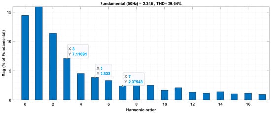
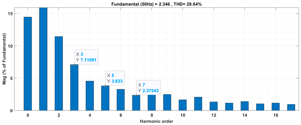
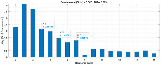
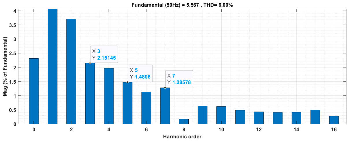
Figure 15 and Figure 16 display the THD of the six-phase stator current for the conventional MPCC and proposed MPCC approaches, respectively. The comparison demonstrates how well the proposed control strategy suppresses harmonic distortion and improves current quality in the six-phase PMSM. As seen in Figure 15, the stator current waveform produced by the traditional MPCC approach has significant harmonic components. The amplitude is around 2.346, the main frequency content is 50 Hz, and the THD is 29.64%. The 3rd, 5th, and 7th harmonics are the dominant low-order harmonics. The conventional MPCC approach has substantial waveform distortion due to these large harmonic components, which leads to increased torque ripple, copper loss, additional thermal stress, and degraded motor performance. In contrast, Figure 16 displays the fast Fourier transform (FFT) spectrum produced using the proposed MPCC approach. With the proposed controller, the current output is a cleaner waveform.
Figure 15.
Current THD of the phase current with the conventional MPCC method.
Figure 16.
Current THD of the phase current with the proposed MPCC method.
The THD of the phase current is calculated according to IEC TR 61000-3-6 standard [48], including harmonic components up to the 50th order:
where is the THD of line current, is root-mean-square (RMS) value of the fundamental current, is the RMS value of the -th harmonic current.
The THD decreases from 29.64% (conventional MPCC) to 6.00% (proposed MPCC), a 79.7% reduction in harmonic distortion. The amplitudes of low-order harmonics are also much less. The third harmonic drops from 7.11% to around 2.15%, the fifth harmonic from 3.83% to roughly 1.48%, and the seventh harmonic from 2.38% to roughly 1.29%. Furthermore, the current waveform quality has significantly improved, as indicated by the higher-order harmonics remaining low (less than 1%). By exploiting the selective voltage vector set and avoiding unnecessary switching transitions, the proposed MPCC method effectively lowers the harmonic distortion, as shown by the comparison of the two FFT spectra. As a result, the proposed controller may improve the six-phase PMSM system’s steady-state performance, torque ripple, efficiency, and sinusoidal currents.
For this study, IEC TR 61000-3-6 is used as a general reference for harmonic characterization and assessment. The THD values shown are calculated directly from motor phase current waveforms simulated using harmonic components from the spectral analysis. Thus, the standard is not applied as a direct grid compliance assessment but as a reference framework for harmonic evaluation. It can be observed that the decrease in the 3rd, 5th, and 7th harmonics is adequate, demonstrating that the proposed voltage vector selection method can effectively suppress the harmonics’ unwanted subspace current in the x-y plane.
5.4. d- and q-Axis Current Responses
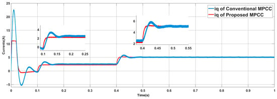
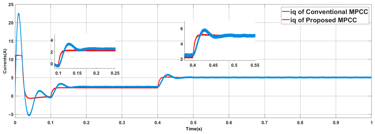
The q-axis current , reaction of the proposed MPCC strategy, and the conventional MPCC approach under dynamic operating conditions are compared in Figure 17. The proposed controller is represented by the red waveform, whereas the conventional controller is represented by the blue waveform. At the startup interval when , the conventional method’s overshoot (the peak current in the q-axis direction) is unusually substantial. The q-axis current reaches over 22 A before abruptly falling to about −5 A. This significant oscillation indicates that there are insufficient transient stability and excessive current variation during the motor startup. In contrast, the proposed MPCC approach provides better dynamic control and a smoother current behavior by significantly reducing the starting overshoot while maintaining a current of about 11 A. The proposed controller stabilizes the system more quickly and with fewer oscillations, as seen by the zoomed-in section from 0.1 s to 0.25 s. The proposed MPCC stabilizes in around 0.025 s, whereas the conventional method stabilizes in ~0.12 s.
Figure 17.
The q-axis current waveforms with the conventional and proposed MPCC schemes.
The proposed MPCC method’s ripple is much lower, indicating greater steady-state performance and more precise current tracking. When the motor experiences a rapid load disturbance at 0.4 s, the two controllers increase the q-axis current to maintain the electromagnetic torque. The conventional approach exhibits oscillating behavior with a peak current of ~5.8 A before stabilization. On the other hand, the proposed MPCC results in a smoother transient response, ensuring less overshoot and rapid recovery. With reduced fluctuation values throughout the transient interval, the proposed controller settles around the reference value of around 5.0 A. The overall picture demonstrates that the proposed MPCC outperforms the conventional approach in terms of dynamic performance. The proposed MPCC provides reduced overshoot, faster settling, lower current ripple, and improved disturbance rejection. These improvements benefit the torque-production smoothness and overall drive performance of the six-phase PMSM system.
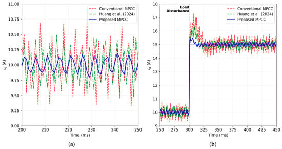
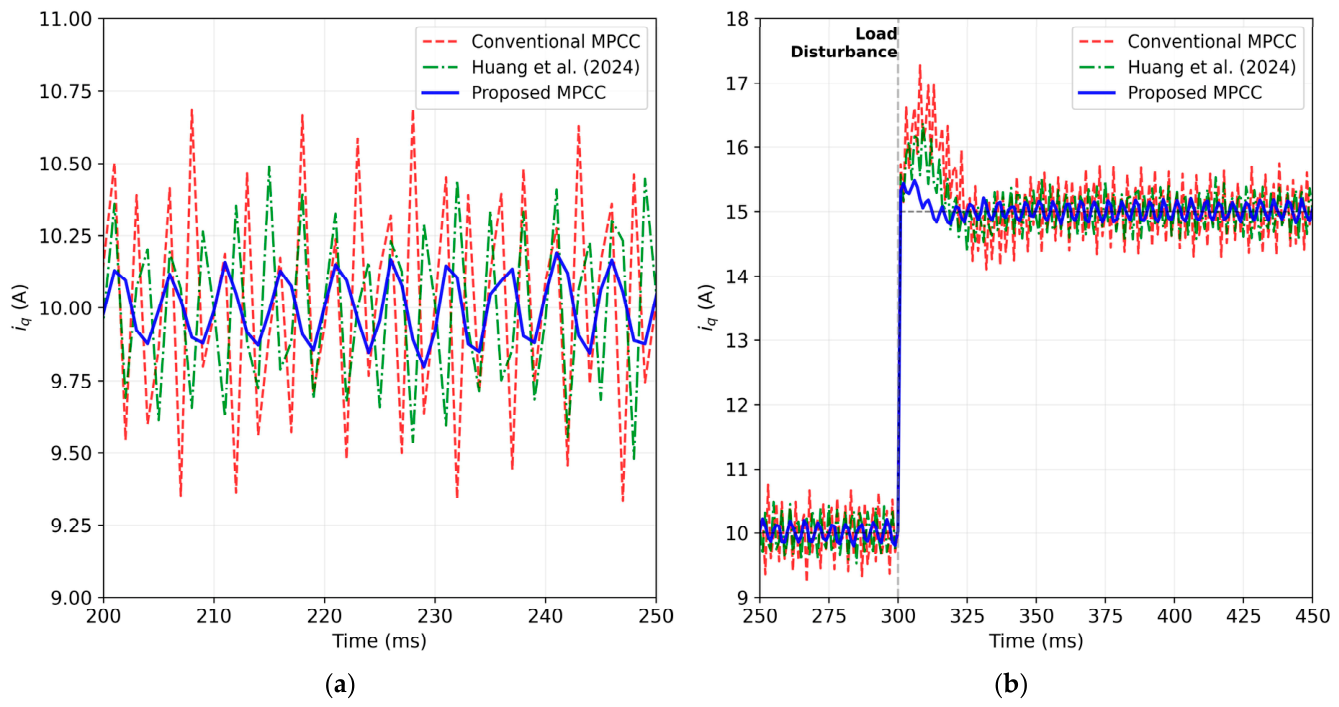
Comparison of the q-axis current waveforms in terms of steady-state ripple and load-disturbance response is shown in Figure 18. The proposed method maintains the lowest steady-state current ripple (±0.15 A) compared to conventional (±0.8 A) and VVV (±0.4 A). For load-disturbance recovery at 0.4 s, the proposed method recovers in 0.02 s, versus 0.05 s for VVV and 0.08 s for conventional.
Figure 18.
Comparison of the q-axis current waveforms in terms of steady-state ripple and load-disturbance response: (a) Steady-state current ripple. (b) Load-disturbance current response [47].
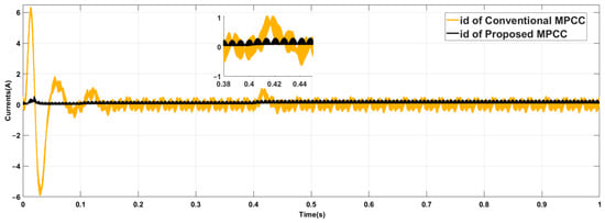
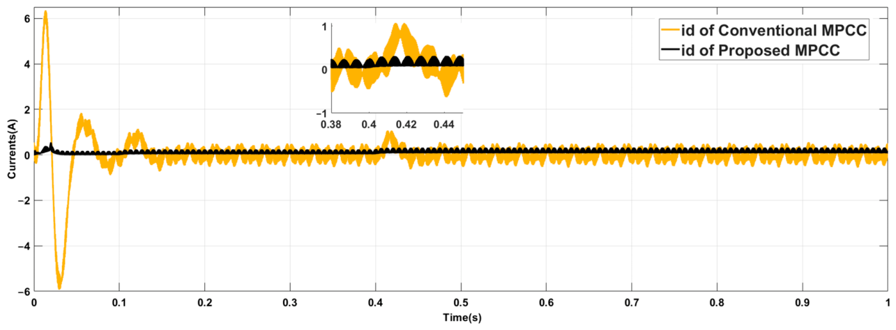
Figure 19 compares the d-axis current responses of the proposed MPCC technique versus the conventional MPCC method. At , the conventional technique exhibits notable transient oscillations, with the d-axis current rapidly fluctuating between +6.2 A and almost −5.8 A. These large amplitude oscillations are linked to excessive current ripple and poor damping during transient operation. In contrast, the proposed MPCC only causes minor oscillations of less than 0.2 A and maintains the d-axis current at a small level close to the reference current of 0 A. During the steady-state period, the conventional controller still shows some rhythmic activity and ripple around the reference current. Due to harmonic distortion and inadequate current control, the waveform range is around 0.8 A. On the other hand, the proposed MPCC effect stabilizes the d-axis current to almost constant values with very little ripple and has a far higher capacity to inhibit these oscillations. It is evident from the expanded section from 0.38 s to 0.45 s that the conventional controller has current variation near 1.0 A, whereas the proposed controller decreases the current difference to about 0.12 A. The system is subjected to the load disturbance at about . Before returning to the steady state, the conventional controller displays an additional brief oscillation with slight overshoot. In contrast, there is minimal overshoot, and the proposed MPCC stabilizes nearly instantly following the disturbance. The behavior demonstrates the proposed controller’s superior dynamic regulation and disturbance rejection. Overall, Figure 19 demonstrates that the proposed MPCC technique outperforms the conventional approach in terms of d-axis current ripple reduction, transient oscillation suppression, and current stability. The six-phase PMSM drive system’s smoothness, efficiency, and torque ripple are all directly impacted by the current decrease.
Figure 19.
The d-axis current waveforms with the conventional and proposed MPCC schemes.
5.5. x- and y-Axis Harmonic Current Suppression
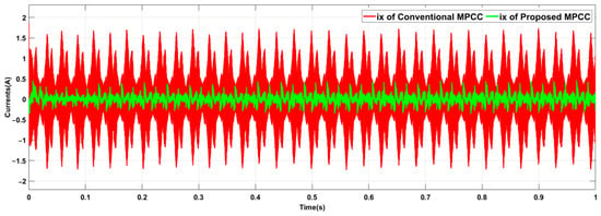
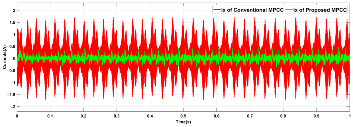
Figure 20 displays the harmonic component of the current of x-subspace . The figure indicates that the conventional MPCC technique’s harmonic current component of x-subspace is greater than that of the proposed MPCC method. This is due to the significant harmonic current oscillations that the conventional MPCC produces over the operational range. This harmonic subspace x-y has several harmonics since the current oscillates roughly between +1.72 A and −1.72 A. The six-phase PMSM drive system’s increased current ripple, copper losses, and unwanted electromagnetic torque pulsations are the causes of the huge oscillations. In contrast, the harmonic current component is reduced by the proposed MPCC approach. The proposed waveform remains within a narrower range of approximately +0.5 A to −0.45 A. The decreased current ripple demonstrates how well the proposed voltage vector selection mechanism minimizes harmonic subspace currents.
Figure 20.
The x-axis current waveforms with the conventional and proposed MPCC schemes.
The proposed controller’s waveform appears smoother and more stable, indicating greater steady-state performance and harmonic suppression. The proposed MPCC suppresses the high-frequency oscillations, whereas the conventional MPCC exhibits periodic high-frequency oscillations throughout the entire simulation interval from 0 to 1 s. There is a large drop in the x-axis harmonic current, which immediately lowers torque ripple, inverter energy loss, and motor drive system thermal stress. Hence, Figure 20 demonstrates that the proposed MPCC approach outperforms the conventional controller in terms of harmonic suppression. The proposed approach effectively reduces the harmonic current components’ magnitudes, resulting in smoother current signals, enhanced dynamic responsiveness, and increased multiphase drive system durability.
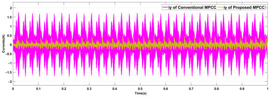
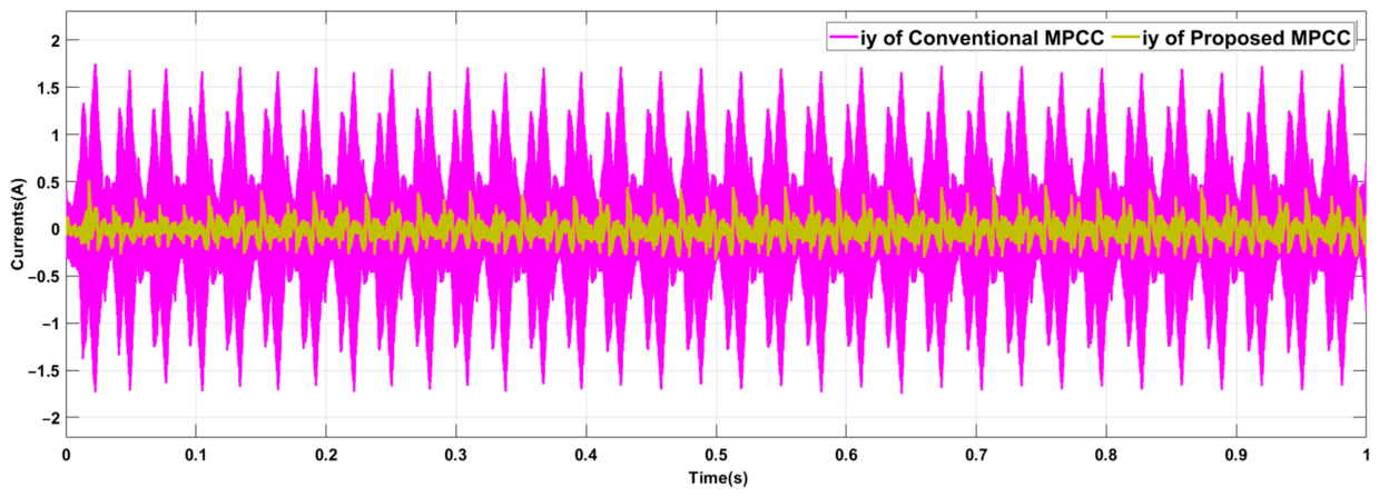
Figure 21 compares the harmonic current component in the y-axis subspace for the proposed MPCC strategy versus the conventional MPCC method. It is evident that, over the whole working range, conventional MPCC causes notable harmonic oscillations in the y-axis current. The current varies between +1.70 A and −1.71 A, indicating a significant harmonic distortion in the six-phase PMSM system’s harmonic subspace. Conversely, the harmonic current part can be significantly reduced by the proposed MPCC. The resultant current falls within a small range of around +0.45 A and −0.4 A, demonstrating how well the proposed current control approach suppresses the harmonic subspace currents. The proposed controller’s capacity to attain more harmonic correction is confirmed by the better waveform, which is smoother, more stable, and less oscillatory than the conventional one. The proposed MPCC approach effectively dampens these ripples and brings the current near the reference value, whereas the conventional controller maintains a continuous high-frequency ripple from 0 s to 1s throughout the simulation duration. The drop in the y-axis harmonic current indicates that the proposed cost-function enhancement and voltage vector optimization successfully lessen the harmonics’ detrimental effects in the x-y plane. Therefore, compared to the conventional control approach for the multiphase motor drive, the results shown in Figure 21 verify that the proposed MPCC method produces superior harmonic suppression performance as well as better steady-state and dynamic performance.
Figure 21.
The y-axis current waveforms with the conventional and proposed MPCC schemes.
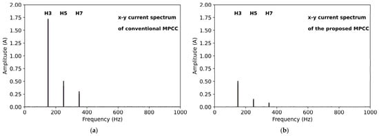
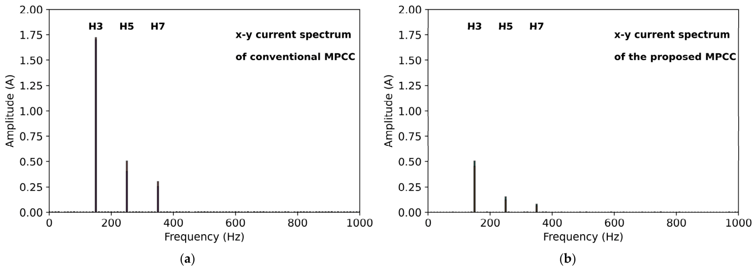
The x-y subspace current spectra with the conventional and proposed MPCC schemes are compared in Figure 22. The conventional method exhibits dominant 3rd, 5th, and 7th harmonic components (150 Hz, 250 Hz, 350 Hz) with amplitudes exceeding 1.5 A, while the proposed method suppresses these to below 0.5 A. Higher-order harmonics (>11th) remain negligible (<0.1 A) in both methods, confirming that the proposed strategy specifically targets low-order harmonic suppression without affecting high-frequency switching components. This spectral characteristic is crucial for applications requiring strict electromagnetic compatibility (EMC) compliance, where low-order harmonic concentration is the primary concern.
Figure 22.
The x-y subspace current spectra with the conventional and proposed MPCC schemes: (a) x-y current spectrum of conventional MPCC. (b) x-y current spectrum of the proposed MPCC.
Table 5 provides a quantitative comparison between the proposed MPCC approach and the regular MPCC strategy for PMSM drive systems. The comparison above demonstrates how much the suggested proposed controller improves both the steady-state and dynamic performance. With the proposed MPCC, the current THD is lowered from 29.64% (conventional MPCC) to 6.00% (proposed MPCC), indicating the superior harmonic suppression performance of the proposed approach.
Table 5.
Performance comparison between the conventional MPCC and the proposed MPCC.
In addition, the q-axis current’s dynamic responsiveness is much improved when the settling period is decreased from around 0.12 s to 0.025 s. There is much less overshoot at startup, which results in smoother transients and improved system stability. Figure 23 compares the average switching frequency of the conventional and proposed MPCC. It is clear that the proposed MPCC strategy achieves an approximately 33% reduction in average switching frequency.
Figure 23.
Average switching frequency analysis between the conventional and proposed MPCC schemes: (a) Switching frequency waveforms. (b) Average switching frequency bar chart.
5.6. Parameter Sensitivity Analysis
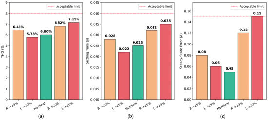
For this study, only the ±20% variation range in stator resistance and inductance can be considered a robustness assessment. These tests are designed to assess sensitivity to typical motor-parameter uncertainties. The results should not, however, be seen as a full validation against any uncertainties of operation and implementation. The results are summarized in Table 6 and Figure 24.
Table 6.
Parameter sensitivity analysis results.
Figure 24.
Parameter sensitivity analysis of the proposed MPCC strategy: (a) Current THD under parameter variation. (b) Settling time under parameter variation. (c) Current error under parameter variation.
The results demonstrate that the proposed MPCC maintains acceptable performance under parameter variations, with phase current THD remaining below 8% and settling time under 0.04 s in all tested cases. The robustness of the proposed MPCC strategy stems from the inherent feedback correction mechanism of MPC and the conservative voltage vector selection strategy.
6. Conclusions
This paper proposes a weighting-factor-free model predictive current control strategy for six-phase PMSM drives. The key innovation lies in a selective voltage vector strategy that reduces the candidate vector set from 64 to 12, thereby inherently constraining harmonic subspace x-y currents without requiring explicit weighting factors in the cost function. A comprehensive dimensionless multi-objective cost function is formulated, incorporating current tracking, switching reduction, current/voltage limits, and torque ripple suppression with individual normalization.
The presented MPCC technique exhibits superior performance compared with the conventional MPCC strategy, as demonstrated by the simulation results. The THD of the phase currents was lowered from 29.64% to 6.00% by the proposed controller, which effectively suppressed the harmonics. There was a notable decrease in the amplitude of the low-order harmonics H3, H5, and H7. With the current ripples in the x-subspace decreasing from ±1.72 A to ±0.5 A and the current in the y subspace decreasing from ±1.7 A to ±0.45 A, the harmonic current ripples in the x-y subspace were also successfully minimized. In addition, the proposed MPCC performed better dynamically in terms of quick settling times, less overshoot, and accurate current tracking. Comparing the proposed controller to the traditional approach, the q-axis’s current settling time was reduced from around 0.12 s to 0.025 s. Compared with the standard MPCC, the proposed MPCC not only improves dynamic stability and overall control performance but also reduces current and torque ripple.
The proposed method eliminates the tedious weighting factor tuning process in conventional MPCC while maintaining superior steady-state and dynamic performance. Parameter sensitivity analysis confirms robust operation under ±20% inductance and resistance variations. These features are particularly attractive for electric vehicle traction drives: the suppression of x-y harmonic currents can reduce stator copper losses and has the potential to improve drive efficiency, which could contribute to extended driving range; the elimination of weighting factor tuning can simplify commissioning over the wide speed and torque range of EV driving cycles; and the low computational burden makes the method amenable to implementation on standard automotive-grade processors.
Future work will focus on:
- Experimental validation on a DSP/FPGA-based six-phase PMSM prototype to verify the computational efficiency and harmonic suppression under real-world switching conditions;
- Extension to fault-tolerant operation under open-phase conditions;
- Integration with modulator-based MPC to achieve fixed switching frequency;
- Investigation of adaptive vector selection for wide-speed range operation, including the field-weakening region.
Author Contributions
Conceptualization, S.T.B. and H.Q.; methodology, S.T.B. and H.Q.; software, B.Z. and W.W.; validation, S.T.B., B.Z. and W.W.; formal analysis, S.T.B. and H.Q.; investigation, S.T.B., B.Z. and W.W.; resources, S.T.B. and H.Q.; data curation, S.T.B. and B.Z.; writing—original draft preparation, S.T.B. and H.Q.; writing—review and editing, S.T.B., B.Z., W.W. and H.Q.; visualization, B.Z. and W.W.; supervision, H.Q.; project administration, H.Q.; funding acquisition, H.Q. All authors have read and agreed to the published version of the manuscript.
Funding
This work was supported in part by the National Natural Science Foundation of China under Grant 52467001, in part by the Guangxi Natural Science Foundation under Grant 2026GXNSFAA00641130, and in part by the Guangxi Science and Technology Plan Project under Grant AD23026112.
Data Availability Statement
The original contributions presented in this study are included in the article. Further inquiries can be directed to the corresponding author.
Acknowledgments
The authors appreciate the reviewers’ insightful comments, and lecturers at Middle Technical University and Guilin University of Electronic Technology for their assistance and guidance.
Conflicts of Interest
The authors declare no conflicts of interest.
Abbreviations
The following abbreviations are used in this manuscript:
| PMSM | permanent magnet synchronous motor |
| MPCC | model predictive current control |
| THD | total harmonic distortion |
| VSI | voltage-source inverter |
| ML | multi-level |
| FOC | field-oriented control |
| DTC | direct torque control |
| MPC | model predictive control |
| DB-MPC | deadbeat MPC |
| EMC | electromagnetic compatibility |
| FCS-MPC | finite control set MPC |
| VVV | virtual voltage vector |
| VSD | vector space decoupling |
| PM | permanent magnet |
| EMF | electromotive force |
| FFT | fast Fourier transform |
| DSP | digital signal processor |
| FPGA | field-programmable gate array |
References
- Sun, J.; Ma, S.; Cui, J.; Wei, H. Harmonic Suppression Model Predictive Control for Dual Three-Phase PMSMs with Full-Space Virtual Voltage-Vector Continuous Regulation. J. Power Electron. 2025, 25, 1171–1176. [Google Scholar] [CrossRef] [Scilit]
- Khanh, P.Q.; Anh, H.P.H.; Thuyen, C.M. Improving PMSM Control Based on Optimizing the Output Membership Function of Fuzzy PI Controller with Weighted Modified Jaya Algorithm. J. Robot. Control 2025, 6, 1938–1948. [Google Scholar] [CrossRef] [Scilit]
- Sepahkar, M.B.; Niasar, A.H. Robust Model-Free Predictive Current and Speed Control of PMSM Drive Based on Nonlinear Disturbance Observer. IET Power Electron. 2025, 18, e70041. [Google Scholar] [CrossRef] [Scilit]
- Niu, L.; Li, X.; Xi, Z. Research on Temperature Rise and Demagnetization Performance of IPMSM Based on Electromagnetic–Thermal Coupling with Typical Working Conditions. World Electr. Veh. J. 2026, 17, 299. [Google Scholar] [CrossRef] [Scilit]
- Levent, A.H.; Lordoglu, A.; Aydeniz, M.G. Design and Optimization of Permanent Magnet Synchronous Motor for Electric Vehicle Applications. In Proceedings of the 2020 IEEE 2nd Global Power, Energy and Communication Conference (GPECOM); IEEE: New York, NY, USA, 2020; pp. 148–151. [Google Scholar] [CrossRef] [Scilit]
- Do, V.-V.; Ngo, D.-K.; Duong, M.-H.L.; Hsieh, M.-F.; Viet, H.Q.; Nguyen, H.V.P.; Thao, N.G.M. Study on Torque Production, Eddy Current Loss, and Demagnetization in Spoke-Type FI-IPM Motor Adopting Segmented Permanent Magnet Configurations. World Electr. Veh. J. 2026, 17, 343. [Google Scholar] [CrossRef] [Scilit]
- Kim, M.; Bae, Y.; Jun, S.; Hwang, S.; Lee, K.; Li, H. Switch Open Fault Detection of Asymmetric 6-Phase PMSM Based on Normalized Stationary Reference Frame dq-axis Currents. In Proceedings of the 2024 IEEE Energy Conversion Congress and Exposition (ECCE); IEEE: New York, NY, USA, 2024; pp. 5516–5522. [Google Scholar] [CrossRef] [Scilit]
- Wang, X.; Sala, G.; Zhang, H.; Gu, C.; Buticchi, G.; Formentini, A.; Gerada, C.; Wheeler, P. Torque Ripple Reduction in Sectored Multi-Three-Phase Machines Based on PWM Carrier Phase Shift. IEEE Trans. Ind. Electron. 2020, 67, 4315–4325. [Google Scholar] [CrossRef] [Scilit]
- Wu, Y.; Huang, Z.; Hofmann, H.; Liu, Y.; Huang, J.; Hu, X.; Peng, J.; Song, Z. Hierarchical Predictive Control for Electric Vehicles with Hybrid Energy Storage System Under Vehicle-Following Scenarios. Energy 2022, 251, 123774. [Google Scholar] [CrossRef] [Scilit]
- Deng, T.; Su, Z.; Li, J.; Tang, P.; Chen, X.; Liu, P. Advanced Angle Field Weakening Control Strategy of Permanent Magnet Synchronous Motor. IEEE Trans. Veh. Technol. 2019, 68, 3424–3435. [Google Scholar] [CrossRef] [Scilit]
- Zhang, J.; Yu, F. A Novel Model Predictive Current Control for Asymmetrical Six-Phase PMSM Drives with an Optimum Duty-Cycle Calculation Scheme. IEEE Access 2023, 11, 8096–8107. [Google Scholar] [CrossRef] [Scilit]
- Bahar, S.T.; Qiu, H.; Neama, D.R.; Hashim, F.F.; Yasseen, H. An Improved Cost Function Based on Model Predictive Current Control for Five-Phase PMSM. Edison J. Electr. Electron. Eng. 2025, 3, 32–38. [Google Scholar] [CrossRef] [Scilit]
- Yan, L.; Zhu, Z.-Q.; Qi, J.; Ren, Y.; Gan, C.; Brockway, S.; Hilton, C. Suppression of Major Current Harmonics for Dual Three-Phase PMSMs by Virtual Multi Three-Phase Systems. IEEE Trans. Ind. Electron. 2022, 69, 5478–5490. [Google Scholar] [CrossRef] [Scilit]
- Mossa, M.A.; Echeikh, H.; Diab, A.A.Z.; Alhelou, H.H.; Siano, P. Comparative Study of Hysteresis Controller, Resonant Controller and Direct Torque Control of Five-Phase IM under Open-Phase Fault Operation. Energies 2021, 14, 1317. [Google Scholar] [CrossRef] [Scilit]
- Bahar, S.T.; Qiu, H. Direct Torque Control Constructed on FCS-MPTC of Five-Phase PMSM Drive. Int. J. Adv. Electr. Eng. 2026, 7, 1–7. [Google Scholar] [CrossRef] [Scilit]
- Wang, H.; Zheng, X.; Yuan, X.; Wu, X. Low-Complexity Model-Predictive Control for a Nine-Phase Open-End Winding PMSM with Dead-Time Compensation. IEEE Trans. Power Electron. 2022, 37, 8895–8908. [Google Scholar] [CrossRef] [Scilit]
- Yu, K.; Wang, Z.; Gu, M.; Wang, X. Universal Control Scheme of Dual Three-Phase PMSM Drives with Single Open-Phase Fault. IEEE Trans. Power Electron. 2022, 37, 14034–14039. [Google Scholar] [CrossRef] [Scilit]
- Zhu, Z.; Wang, S.; Shao, B.; Yan, L.; Xu, P.; Ren, Y. Advances in Dual-Three-Phase Permanent Magnet Synchronous Machines and Control Techniques. Energies 2021, 14, 7508. [Google Scholar] [CrossRef] [Scilit]
- Luan, T.; Wang, Z.; Long, Y.; Zhang, Z.; Li, Q.; Zhu, Z.; Liu, C. Multi-Virtual-Vector Model Predictive Current Control for Dual Three-Phase PMSM. Energies 2021, 14, 7292. [Google Scholar] [CrossRef] [Scilit]
- Gu, M.R.; Wang, Z.; Yu, K.L.; Wang, X.; Cheng, M. Interleaved Model Predictive Control for Three-Level Neutral-Point-Clamped Dual Three-Phase PMSM Drives with Low Switching Frequencies. IEEE Trans. Power Electron. 2021, 36, 11618–11630. [Google Scholar] [CrossRef] [Scilit]
- Bahar, S.T.; Omar, R.G. Permanent Magnet Synchronous Motor Torque Ripple Reduction Using Predictive Torque Control. J. Eng. Sustain. Dev. 2023, 27, 394–406. [Google Scholar] [CrossRef] [Scilit]
- Wang, B.; Jin, S.; Liu, G. Comprehensive Review of Finite-Control-Set Model Predictive Control Methods for Permanent-Magnet Synchronous Motors. Chin. J. Electr. Eng. 2026, 12, 240–259. [Google Scholar] [CrossRef] [Scilit]
- Bahar, S.T.; Wang, W.; Qiu, H. AI-Enhanced Model Predictive and Active Disturbance Rejection Control for High-Performance Permanent Magnet Synchronous Motor Drives. Energies 2026, 19, 2574. [Google Scholar] [CrossRef] [Scilit]
- Serra, J.; Cardoso, A.J.M. A Simplified Model Predictive Control for Asymmetrical Six-Phase Induction Motors That Eliminates the Weighting Factor. Machines 2022, 10, 1189. [Google Scholar] [CrossRef] [Scilit]
- Luo, Y.; Liu, C. Model Predictive Control for a Six-Phase PMSM Motor with a Reduced-Dimension Cost Function. IEEE Trans. Ind. Electron. 2020, 67, 969–979. [Google Scholar] [CrossRef] [Scilit]
- Gonzalez, O.; Ayala, M.; Romero, C.; Delorme, L.; Rodas, J.; Gregor, R.; Gonzalez-Prieto, I.; Duran, M.J. Model Predictive Current Control of Six-Phase Induction Motor Drives Using Virtual Vectors and Space Vector Modulation. IEEE Trans. Power Electron. 2022, 37, 7617–7628. [Google Scholar] [CrossRef] [Scilit]
- Yao, M.; Peng, J.; Sun, X. Robust Model Predictive Current Control for Six-Phase PMSMS with Virtual Voltage Vectors. J. Power Electron. 2022, 22, 1885–1896. [Google Scholar] [CrossRef] [Scilit]
- Wang, Z.; Wang, X.; Yang, X.; Wen, C.; Gong, Y.; Hu, Y. Mitigation of DC-Link Current Ripple for Dual Three-Phase Flux-Adjustable Hybrid PMAC Drives Using Collaborative Switching Strategy. IEEE Trans. Ind. Electron. 2020, 67, 7202–7216. [Google Scholar] [CrossRef] [Scilit]
- Gu, M.; Wang, Z.; Wang, B. Optimization of Torque Ripple for Low-Carrier-Ratio Dual Three-Phase PMSM with Pulse Pattern Control. IEEE Trans. Power Electron. 2023, 38, 15091–15096. [Google Scholar] [CrossRef] [Scilit]
- Han, X.; Jiang, D.; Zou, T.; Qu, R.; Yang, K. Two-Segment Three-Phase PMSM Drive with Carrier Phase-Shift PWM for Torque Ripple and Vibration Reduction. IEEE Trans. Power Electron. 2019, 34, 588–599. [Google Scholar] [CrossRef] [Scilit]
- Mohanraj, D.; Chokkalingam, B.; Verma, R.; Sathiyasekar, K.; Mihet-Popa, L. Sensorless Model Predictive Direct Torque Regulation with Modified Switching Table for Double-Pole Salient Machines to Improve the Performance. IEEE Access 2026, 14, 52208–52218. [Google Scholar] [CrossRef] [Scilit]
- Liang, G.; Liao, W.; Zhang, Z.; Ni, D.; Huang, S.; Li, M.; Wen, Y.; Gao, J. An Optimized Pulse Width Modulation for Dual Three-Phase PMSM Under Low Carrier Ratio. IEEE Trans. Power Electron. 2022, 37, 3062–3072. [Google Scholar] [CrossRef] [Scilit]
- Liang, G.; Huang, S.; Liao, W.; Zhang, Z.; Liu, Y.; Feng, C.; Wu, X.; Huang, S. An Optimized Modulation of Torque and Current Harmonics Suppression for Dual Three-Phase PMSM. IEEE Trans. Transp. Electrif. 2024, 10, 3443–3454. [Google Scholar] [CrossRef] [Scilit]
- Ren, Y.; Zhu, Z.Q.; Green, J.E.; Li, Y.; Zhu, S.; Li, Z. Improved Duty-Ratio-Based Direct Torque Control for Dual Three-Phase Permanent Magnet Synchronous Machine Drives. IEEE Trans. Ind. Appl. 2019, 55, 5843–5853. [Google Scholar] [CrossRef] [Scilit]
- Zhang, K.; Quan, L.; Liu, G. Improved Duty Cycle Modulation Direct Torque Control for Dual Three-Phase PMSM with Voltage Vector Online Optimization. J. Power Electron. 2022, 22, 222–233. [Google Scholar] [CrossRef] [Scilit]
- Rao, A.; Ma, C.; Song, W.; Shahid, M.B.; Hassan, M. Efficient and Weighting Factor-Free Predictive Current Control for Three-Level PMSM Drives via Cost Function Division. IET Electr. Power Appl. 2025, 19, e70111. [Google Scholar] [CrossRef] [Scilit]
- Wang, S.; Zhang, Q.; Zhao, J.; Wu, D. Multi-Amplitude Voltage Vector MPTC for Dual Three-Phase PMSMs with Low Torque Ripple. J. Power Electron. 2024, 24, 68–77. [Google Scholar] [CrossRef] [Scilit]
- Wang, X.; Yan, H.; Sala, G.; Buticchi, G.; Gu, C.; Zhao, W.; Xu, L.; Zhang, H. Selective Torque Harmonic Elimination for Dual Three-Phase PMSMs Based on PWM Carrier Phase Shift. IEEE Trans. Power Electron. 2020, 35, 13255–13269. [Google Scholar] [CrossRef] [Scilit]
- Bahar, S.T.; Qiu, H. Amelioration of Traditional PI Boost Converter Utilizing Linear Active Disturbance Rejection Controller–Mode Predictive Control Strategy. Int. J. Robot. Control Syst. 2026, 6, 305–323. [Google Scholar] [CrossRef] [Scilit]
- Xu, Y.; Wang, G.; Zou, J.; Yan, H.; Zheng, B. Current Harmonic Suppression in Dual Three-Phase Permanent Magnet Synchronous Machine with Extended State Observer. IEEE Trans. Power Electron. 2020, 35, 12166–12180. [Google Scholar] [CrossRef] [Scilit]
- Yang, L.; Zhu, Z.Q.; Bin, H.; Gong, L. Spectral Analysis and Sideband Harmonic Cancellation of Six-Step Operation with Low Carrier-Fundamental Frequency Ratio for High-Speed Brushless DC Drives. IEEE Trans. Ind. Electron. 2021, 68, 7778–7792. [Google Scholar] [CrossRef] [Scilit]
- Gu, M.; Wang, Z.; Liu, P.; He, J. Comparative Study of Advanced Modulation and Control Schemes for Dual Three-Phase PMSM Drives with Low Switching Frequencies. IEEE Trans. Transp. Electrif. 2024, 10, 962–975. [Google Scholar] [CrossRef] [Scilit]
- Wang, Z.; Li, Y.; Yu, K.; Gu, M. Position Sensorless Control of Dual Three-Phase IPMSM Drives with High-Frequency Square-Wave Voltage Injection. IEEE Trans. Ind. Electron. 2023, 70, 9925–9934. [Google Scholar] [CrossRef] [Scilit]
- Zheng, B.; Zanchetta, P.; Wang, L.; Zou, J.; Yu, G.; Xu, Y. High-Frequency Current Harmonic Analysis and Suppression in Dual Three-Phase PMSMs with Advanced Carrier Phase-Shift PWM. IEEE Trans. Power Electron. 2024, 39, 2569–2581. [Google Scholar] [CrossRef] [Scilit]
- Cui, J.; Zhao, W.; Tao, T. Optimized Control Set Model Predictive Control for Dual Three-Phase PMSM With Minimum Error Duty Cycle Regulation. IEEE Trans. Power Electron. 2024, 39, 1319–1332. [Google Scholar] [CrossRef] [Scilit]
- Agoro, S.; Husain, I. Model-Free Predictive Current and Disturbance Rejection Control of Dual Three-Phase PMSM Drives Using Optimal Virtual Vector Modulation. IEEE J. Emerg. Sel. Top. Power Electron. 2023, 11, 1432–1443. [Google Scholar] [CrossRef] [Scilit]
- Huang, Y.; Liu, S.; Pang, R.; Liu, X.; Rao, X. Model Predictive Current Control for Six-Phase PMSM with Steady-State Performance Improvement. Energies 2024, 17, 5273. [Google Scholar] [CrossRef] [Scilit]
- IEC TR 61000-3-6:2008; Electromagnetic Compatibility (EMC)–Part 3-6: Limits–Assessment of Emission Limits for the Connection of Distorting Installations to MV, HV and EHV Power Systems. International Electrotechnical Commission: Geneva, Switzerland, 2008.

Disclaimer/Publisher’s Note: The statements, opinions and data contained in all publications are solely those of the individual author(s) and contributor(s) and not of MDPI and/or the editor(s). MDPI and/or the editor(s) disclaim responsibility for any injury to people or property resulting from any ideas, methods, instructions or products referred to in the content. |
© 2026 by the authors. Published by MDPI on behalf of the World Electric Vehicle Association. Licensee MDPI, Basel, Switzerland. This article is an open access article distributed under the terms and conditions of the Creative Commons Attribution (CC BY) license.