


Abstract
This paper is based on model-free adaptive control with data-driven control and explores its application in the motion control of intelligent vehicles. Based on experiments investigating the feasibility and effectiveness of standard control algorithms, the paper examines four key parameters and error control metrics in the control algorithm. Using methods such as factor perturbation analysis, linear fitting, and correlation analysis, parameter sensitivity analysis was conducted. The parameter tuning problem was transformed into a multi-objective optimisation problem, and an optimisation model was established. An enhanced multi-objective genetic evolutionary algorithm (MO-GA) based on NSGA-II is proposed to address the multi-objective optimization problem. Through three experimental scenarios under the Hammerstein nonlinear system, the effectiveness of the improved algorithm was verified. Based on the MatlabR2024b/Carsim2020 platform, joint simulation experiments were conducted on the Audi A6-Avant models under dual-lane shifting and serpentine operating conditions, verifying the portability of the improved algorithm.
1. Introduction
Currently, numerous control algorithms are employed for vehicle trajectory tracking. For the longitudinal and lateral issues in autonomous vehicle trajectory tracking, there are PID Control [1], Model Predictive Control [2], Sliding Mode Control [3], and Nonlinear Model Predictive Control (NMPC) [4]. Regarding the design of lateral motion controllers for intelligent vehicles, the research focus is gradually shifting from Model-Based Control (MBC) [5,6,7] to Data-Driven Control (DDC) [8]. Among these, Model-Free Adaptive Control (MFAC), as a typical algorithm of DDC, has attracted increasing attention from scholars in recent years [9,10,11].
The MFAC algorithm involves four key parameters that require manual configuration. Studies have found that the quality of the initial parameter values directly affects the control performance of MFAC. To enhance the control accuracy of the prototype MFAC theory, a limited number of optimization studies focusing on the MFAC algorithm have been conducted, with the primary research direction being parameter tuning optimization [12,13,14]. The existing research can be categorized into two approaches: parameter tuning algorithms borrowed from established PID control methods, and parameter tuning algorithms based on intelligent meta-heuristic algorithms. The tuning approach derived from PID control is applicable to the direct MFAC scheme, while the meta-heuristic-based tuning approach is applicable to the indirect MFAC scheme. This paper primarily investigates the application of indirect MFAC technology.
Reference [15] proposes a Cross-mixing Global Artificial Bee Colony algorithm (CGABC) to optimize and tune the key parameters of MFAC, introducing an improved Integral Absolute Error (IAE) index to evaluate the performance difference before and after optimization, with simulation results verifying the effectiveness of the improvement. In 2019, a team from South China University of Technology employed a genetic algorithm to explore the relationships between key parameters in the MFAC scheme, transforming the multi-parameter optimization problem into a single-parameter optimization problem. Through parameter correlation and dynamization, they proposed an improved MFAC control scheme that avoids overshoot or oscillations during convergence and successfully applied it to a commercial refinery unit [16]. In 2020, a team from Chongqing University of Technology proposed a hybrid Particle-swarm and Krill-herd intelligent algorithm (PSOKH), which possesses a balanced capability for global exploration and local exploitation, enabling more effective parameter optimization, demonstrating superior tracking performance, reducing overshoot to a certain extent, and enhancing the overall stability of the control system [17].
Currently, most proposed parameter tuning methods still heavily rely on PID parameter tuning strategies, lacking autonomous and systematic research based on MFAC theory. If an effective parameter tuning algorithm can be designed based on MFAC theory, it would yield favorable control effects. Therefore, further investigating effective parameter tuning algorithms for the initial configuration of MFAC parameters based on MFAC theory holds significant theoretical and practical importance for the lateral control of Intelligent Vehicles (IVs) [18,19].
In summary, the main contributions of this paper can be summarized as follows:
- (1)
- A systematic parameter sensitivity analysis method for MFAC is proposed.
- (2)
- A multi-objective optimization-based parameter tuning model for MFAC is constructed.
- (3)
- An enhanced multi-objective genetic evolutionary algorithm (MO-GA) based on NSGA-II is proposed
2. Materials and Methods
2.1. Model-Free Adaptive Control
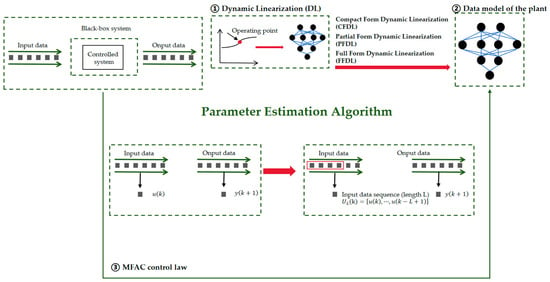
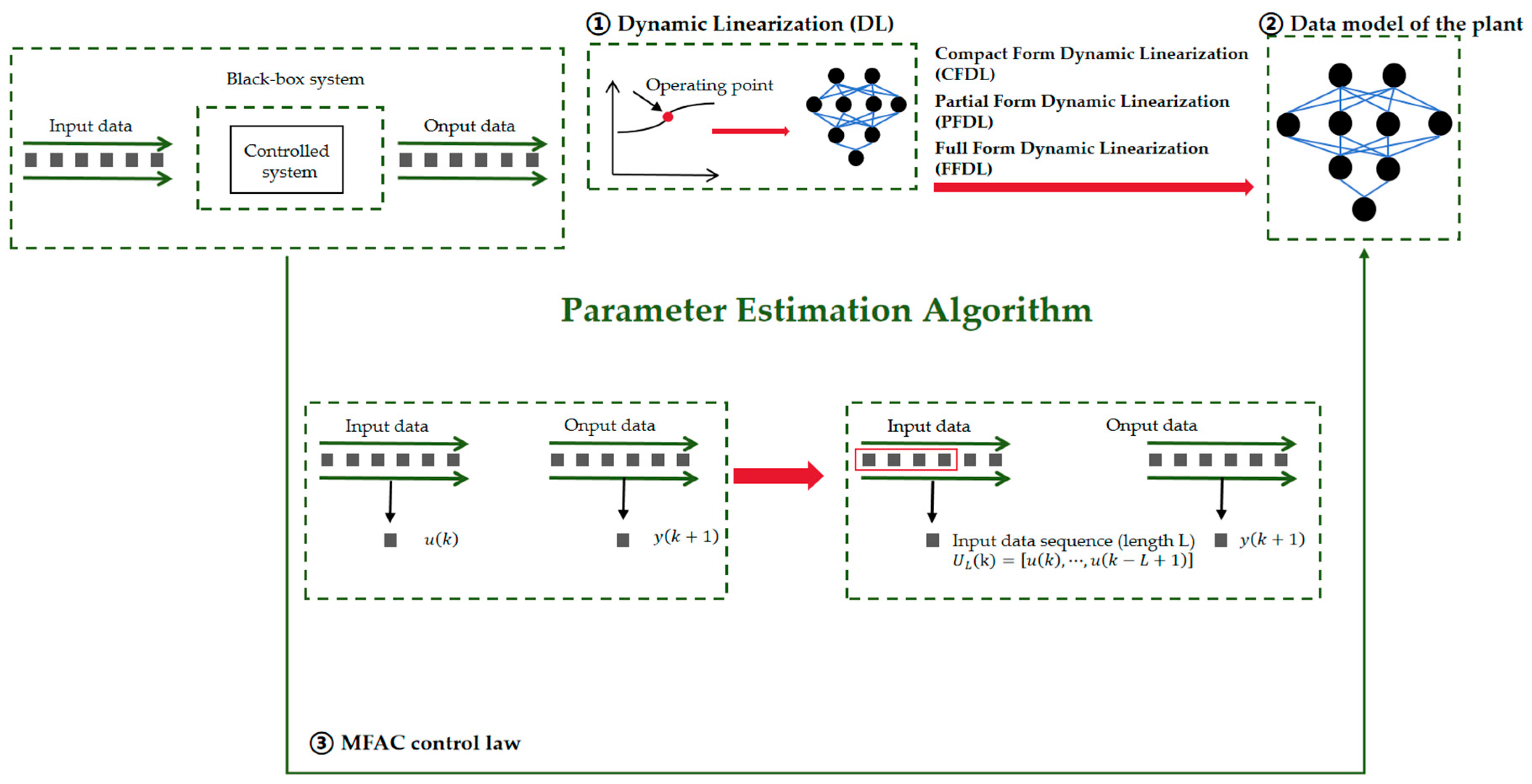
Without loss of generality, a Single-input Single-output (SISO) system is taken as an example to illustrate the control principle of MFAC. Figure 1 presents the control principle of MFAC.
Figure 1.
Presents the control principle of MFAC.
The MFAC algorithm is based on the Compact-form Dynamic Linearization (CFDL) technique. By introducing the Pseudo-partial Derivative (PPD), it employs a series of equivalent dynamic linearized models at the current operating point of the controlled system to replace the general discrete-time nonlinear system. Moreover, it utilizes only the Input-output (I/O) data of the controlled plant to estimate the PPD or pseudo-gradient vector, online, thereby achieving MFAC control of the nonlinear system.
2.1.1. CFDL Data Model Formulation for Nonlinear Systems
In industrial control applications, most nonlinear system models can be described as the general SISO nonlinear discrete-time system as shown in the following equation:
In Equation (1), , and represents the unknown order of the system; and are the output and input of the controlled system, respectively, and is an unknown nonlinear function. Upon satisfying the following assumptions, Equation (1) can be transformed into the general CFDL data model form.
Assumption 1.
The nonlinear system described by Equation (1) is convergent, i.e., the input and output are observable and controllable.
Assumption 2.
is a smooth, differentiable function, and its partial derivatives with respect to the input variables at any time instant are all continuous.
Assumption 3.
The controlled system (Equation (1)) satisfies the generalized Lipschitz condition. That is, for ( ), the inequality given in Equation (2) holds:
When system (1) satisfies the above assumptions, there necessarily exists a bounded time-varying parameter such that system (1) can be expressed as Equation (3) below, which is termed the CFDL data model of the controlled plant:
where denotes the PPD of the controlled plant, and satisfies the boundedness condition with respect to .
2.1.2. Control Law Design
The control input criterion function is given as follows in Equation (4):
In Equation (4), is the desired value, and is the weighting factor. Substituting Equation (3) into the criterion function (4) gives Equation (5). To minimize Equation (5), the specific procedure is as follows: differentiating Equation (5) with respect to yields Equation (6). Setting Equation (6) to zero and rearranging the terms yields the control algorithm given in Equation (7):
To enhance the generality of the control algorithm, a step-size factor is introduced into the CFDL-MFAC control law, resulting in the control algorithm given in Equation (8), where .
2.1.3. PPD Estimation Algorithm
To ensure a certain degree of robust stability for the parameter estimation algorithm, the CFDL-MFAC employs the PPD estimation criterion function given in Equation (9):
By minimizing Equation (10) with respect to , the PPD estimation algorithm for CFDL-MFAC is obtained as follows:
where denotes the estimated value of the PPD. It should be noted that is the introduced step-size factor, which is identical to the parameter in the control algorithm of Equation (8). Its purpose is to enhance the flexibility and general applicability of the parameter estimation algorithm.
Under Assumptions 1 to 3, the MFAC algorithm can theoretically guarantee bounded-input bounded-output (BIBO) stability of the closed-loop system. The rigorous mathematical proof of this conclusion can be found in references [9,10,11]. Specifically, Assumption 1 ensures the observability and controllability of the system, Assumption 2 ensures the smoothness of the system, and the generalized Lipschitz condition in Assumption 3 ensures the boundedness of the PPD (pseudo-partial derivative). Under the above premises, the closed-loop system formed by the control law (Equation (8)) and the PPD estimation algorithm (Equation (10)) ensures that both the tracking error and the control input are bounded, thereby guaranteeing the stability of the system.
2.2. Parameter Sensitivity Analysis
In this paper, three nonlinear discrete-time systems, as given in Equation (11), are considered. Among them, system H1 exhibits overshoot without oscillation, system H2 exhibits both overshoot and oscillation, and system H3 exhibits neither overshoot nor oscillation.
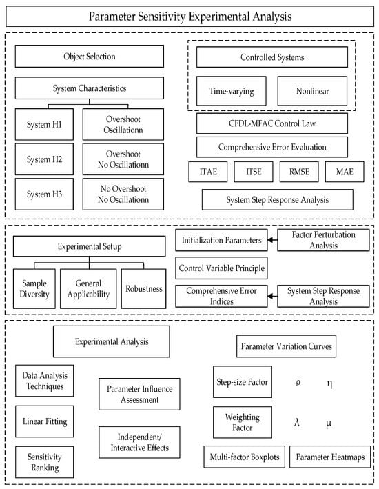
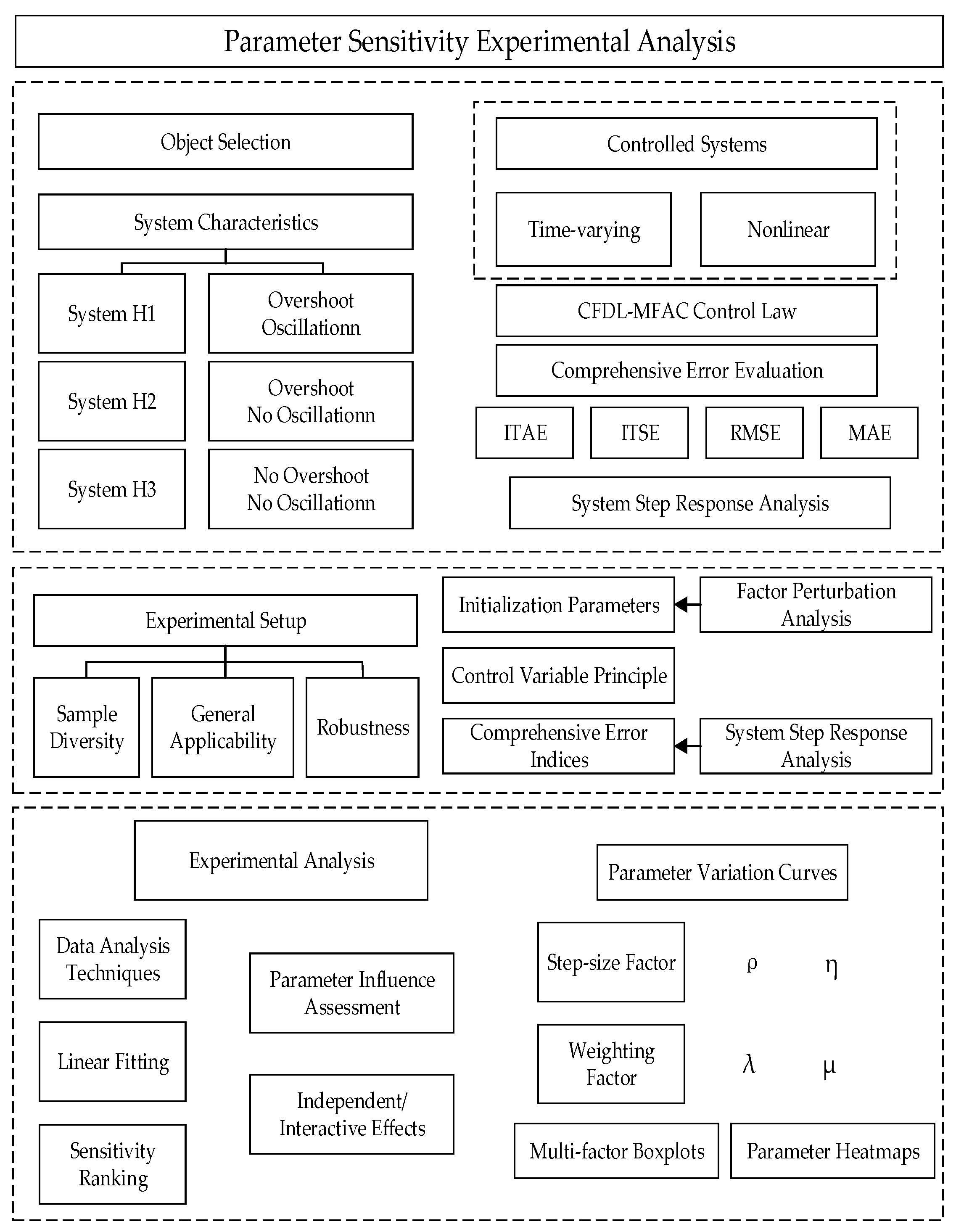
For the three types of nonlinear controlled systems, the technical roadmap for parameter sensitivity analysis is presented in Figure 2. Under the initial value conditions, a rate-of-change threshold is specified, and linear fitting is adopted to generate the variation curves of the four evaluation indices given in Equation (12) with respect to the four parameters under fixed rates of change. In Equation (12), and represent the discrete-time forms of the Integral of Time-weighted Absolute Error (ITAE) and the Integral of Time-weighted Squared Error (ITSE), respectively. By adjusting the index , the time required for the control system to reach stability—namely, the settling time—can be regulated, while the index serves to prevent large deviations during the regulation process. The magnitudes of the indices and are of the same order as the system output error, and therefore can directly reflect the control error. Subsequently, the experimental data are compiled to generate multi-factor boxplots, which intuitively illustrate the influence of each parameter on the control performance. Finally, parameter heatmaps corresponding to the four evaluation indices are constructed to further demonstrate the impact of each parameter.
Figure 2.
Parameter sensitivity experimental analysis.
2.3. Results and Analysis of Parameter Sensitivity
2.3.1. Sensitivity Analysis Experiment for System H1
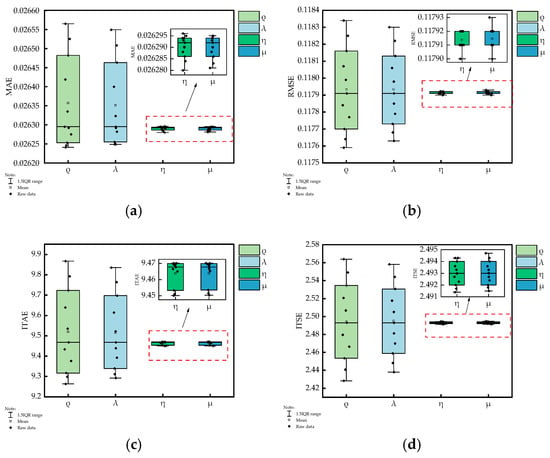
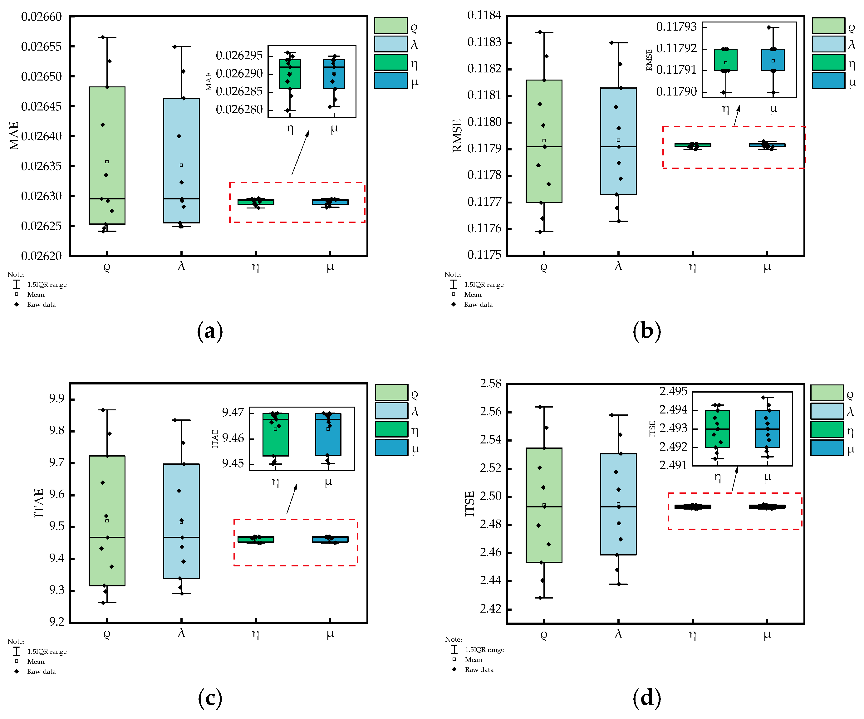
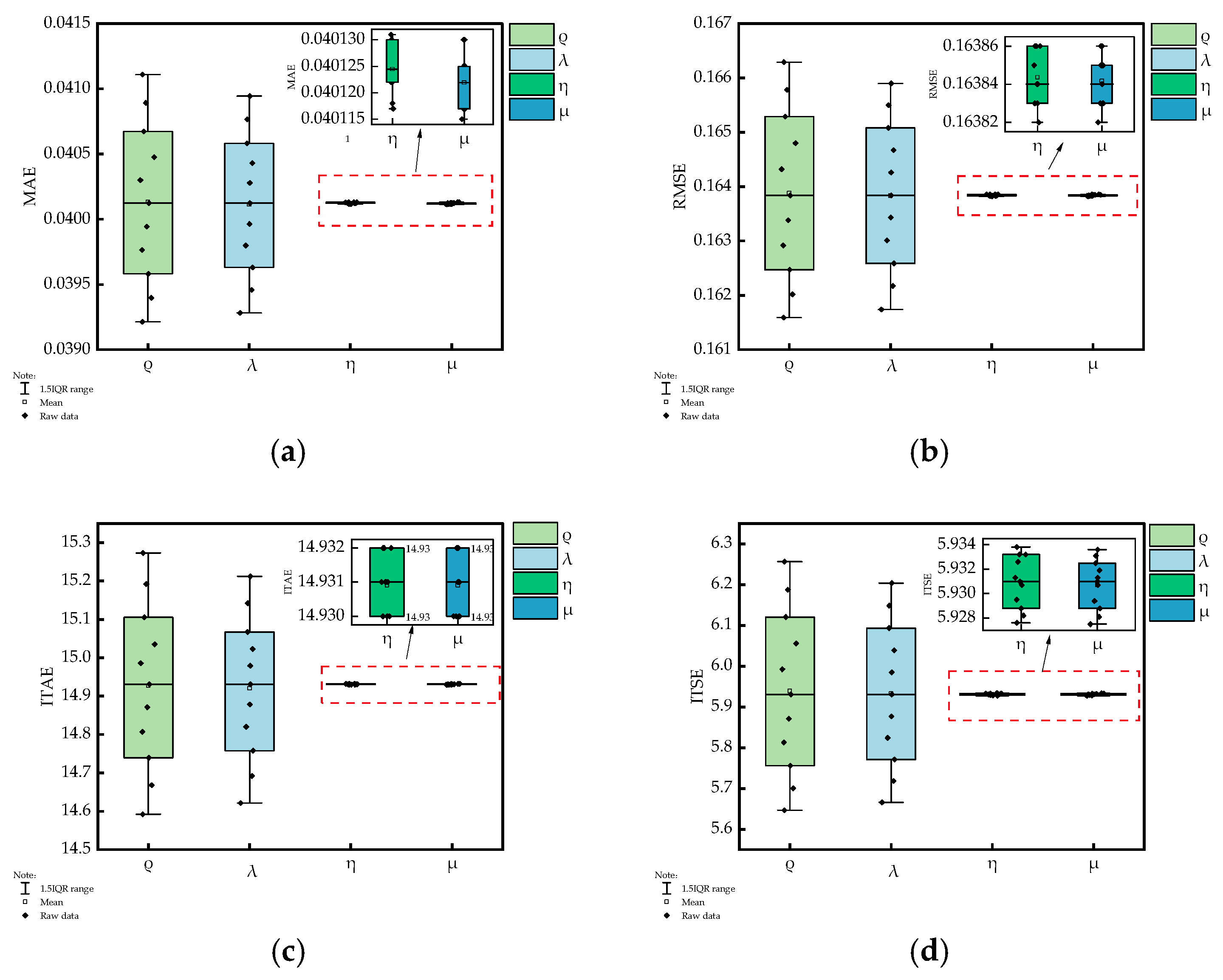
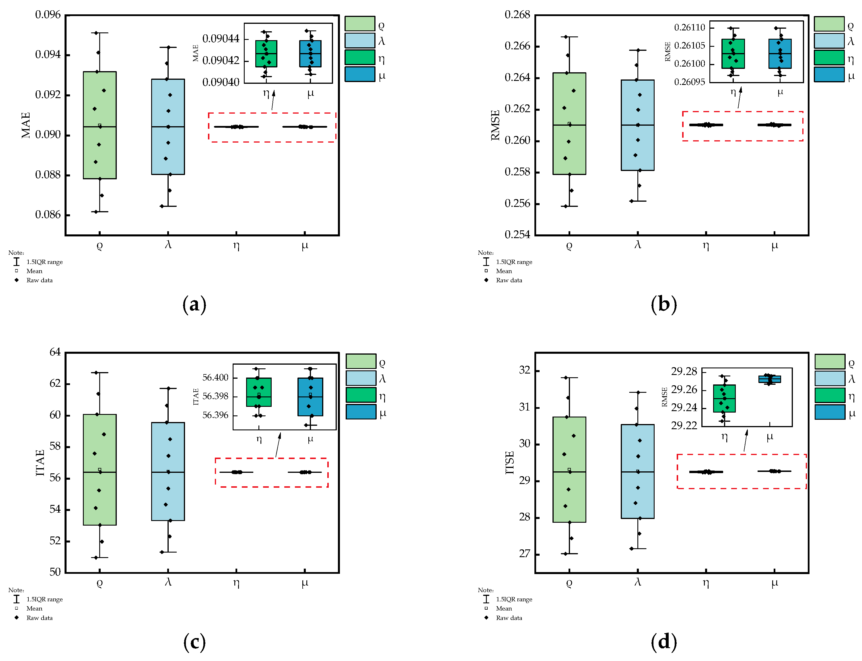
The experimental results of System H1 are presented in Figure A1 and Figure 3. Specifically, Figure A1 shows the line charts of the four evaluation indices , , , and for each parameter of System H1 under a rate of change, while Figure 3 presents the boxplots of these evaluation indices under variations of each parameter. From Figure A1 and Figure 3, the following conclusions can be drawn: for the controlled system H1, among the parameters of the CFDL-MFAC control law, and have a significant impact on the control performance. Specifically, parameter is positively correlated with each error evaluation index, while parameter is negatively correlated with each evaluation index. In contrast, parameters and exhibit less significant influence compared with and , indicating that, for the control performance of the CFDL-MFAC control law, parameters and are highly sensitive.
Figure 3.
Boxplot of the performance indices for system H1 under different parameters. (a) MAE; (b) RMSE; (c) ITAE; (d) ITSE.
2.3.2. Sensitivity Analysis Experiment for System H2
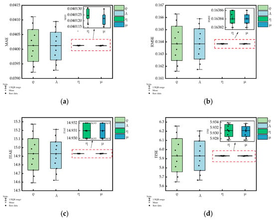
The experimental results for system H2 are shown in Figure A2 and Figure 4. For the controlled system H2, among the parameters of the CFDL-MFAC control law, and are identified as the ones that significantly affect the control performance. Specifically, parameter is negatively correlated with each error evaluation index, while parameter is positively correlated with each evaluation index. In contrast, parameters and have less significant influences compared with and . Thus, parameters and are highly sensitive with respect to the controlled performance of the CFDL-MFAC control law.
Figure 4.
Boxplot of the performance indices for system H2 under different parameters. (a) MAE; (b) RMSE; (c) ITAE; (d) ITSE.
2.3.3. Sensitivity Analysis Experiment for System H3
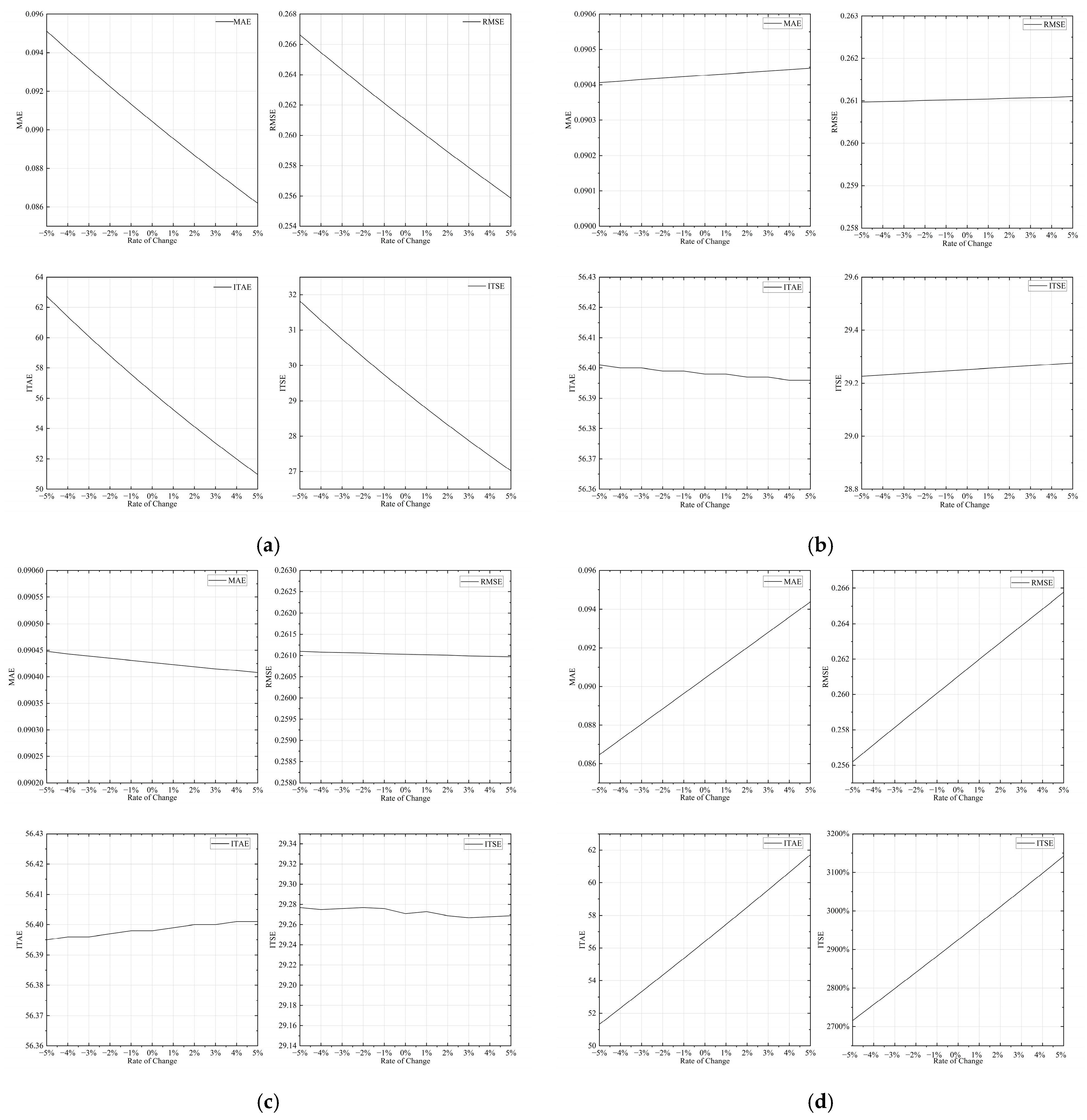
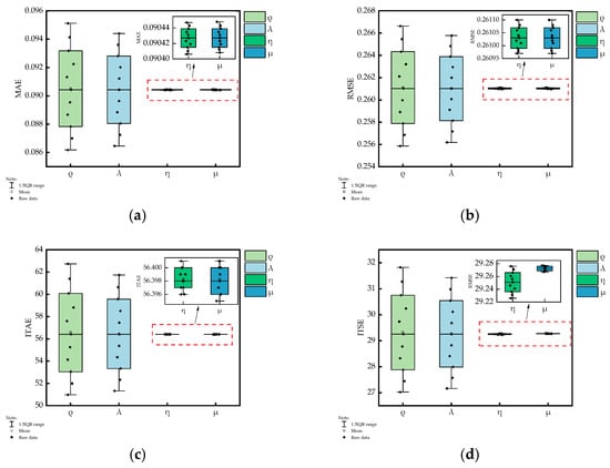
The experimental results for system H3 are shown in Figure A3 and Figure 5. For the controlled system H3, among the parameters of the CFDL-MFAC control law, and are identified as the ones that significantly affect the control performance. Specifically, parameter is negatively correlated with each error evaluation index, while parameter is positively correlated with each evaluation index. In contrast, parameters and have less significant influences compared with and . Thus, parameters and are highly sensitive with respect to the controlled performance of the CFDL-MFAC control law.
Figure 5.
Boxplot of the performance indices for system H3 under different parameters. (a) MAE; (b) RMSE; (c) ITAE; (d) ITSE.
The experimental results presented in Figure 3, Figure 4 and Figure 5 qualitatively demonstrate the sensitivity differences of each parameter with respect to the control performance across the three types of systems. It is consistently observed that parameters and exert more significant influences on the control performance than parameters and in all three systems. To quantitatively evaluate the effects of the four key parameters on the control performance, a correlation analysis between the control performance and each parameter is further conducted for the three systems.
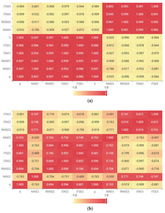
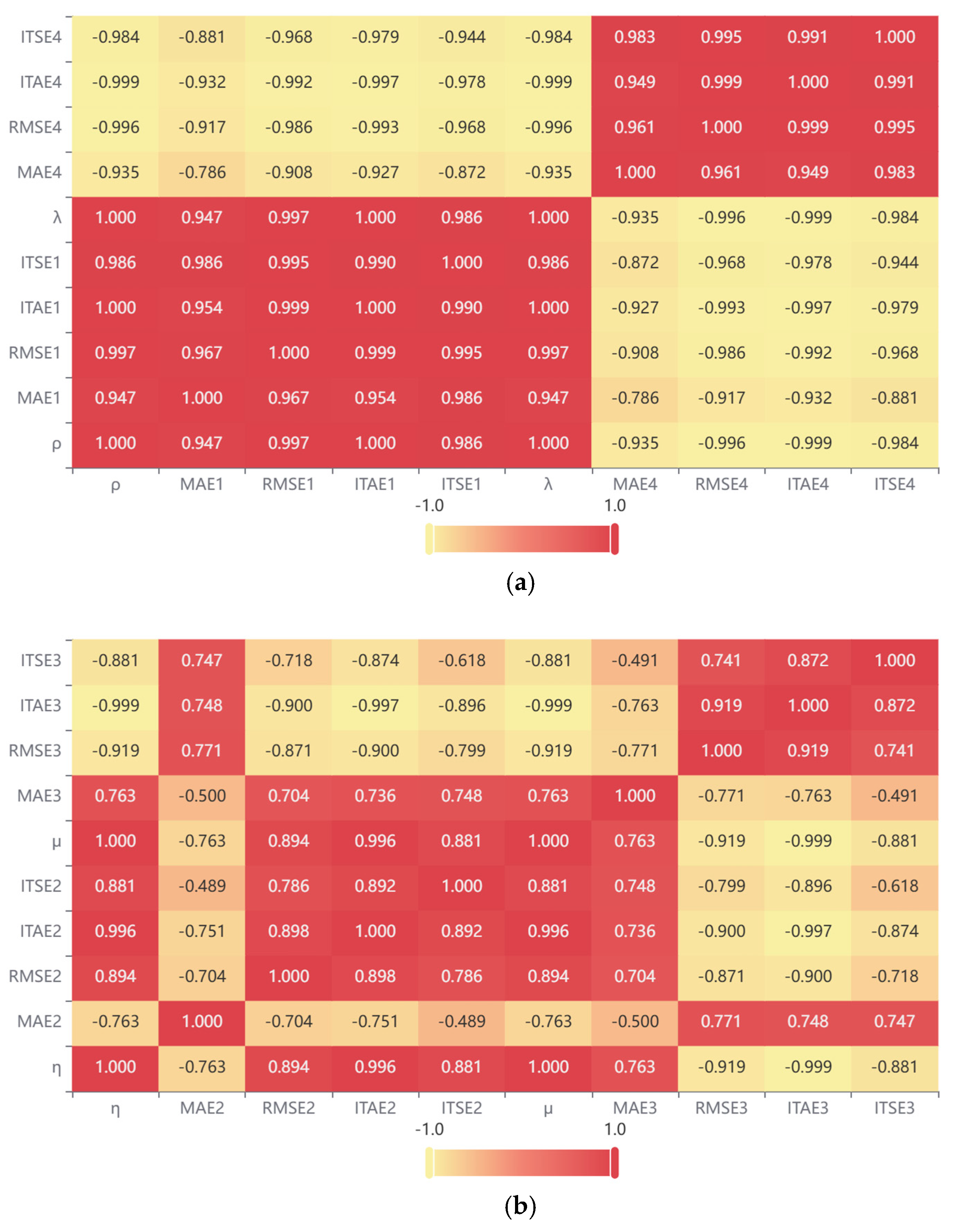
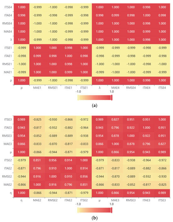
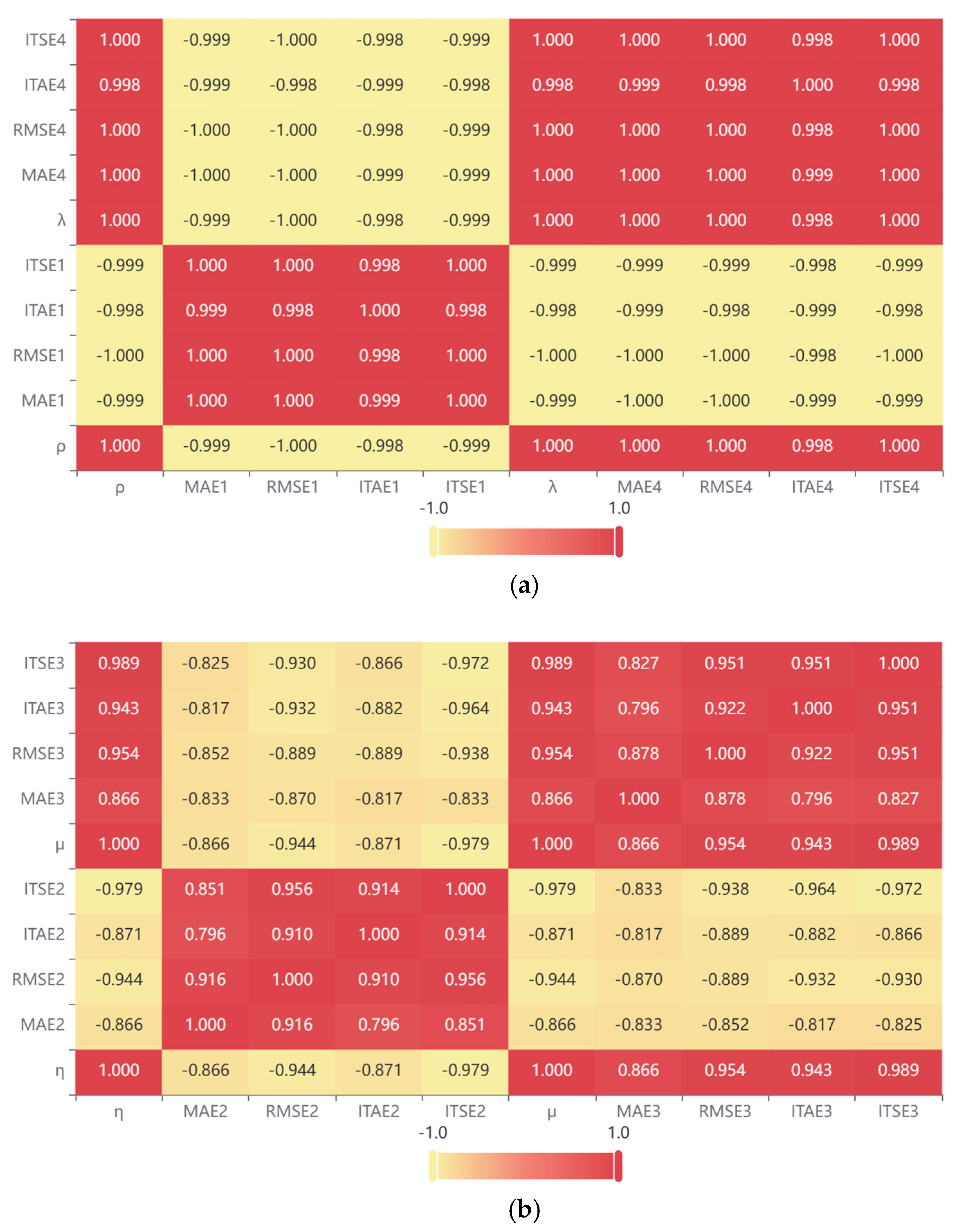
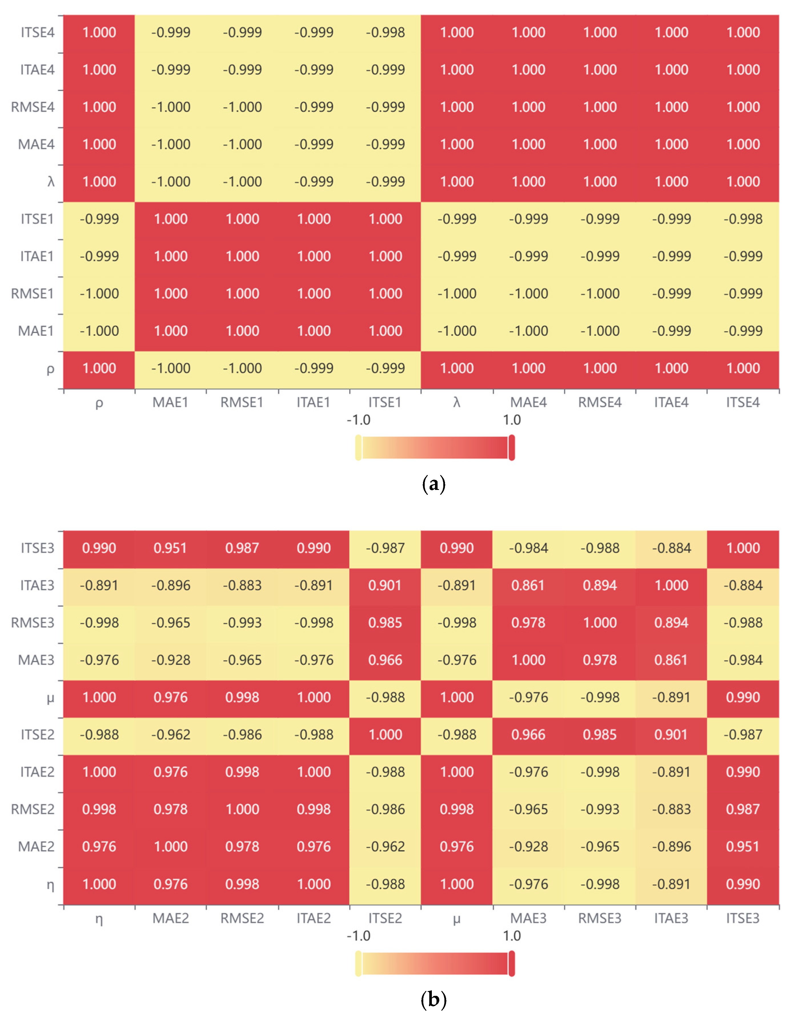
In view of the data characteristics and experimental requirements of this study, the Spearman correlation analysis is adopted. In this experiment, the four parameters are divided into two groups: parameters and constitute one group, while parameters and form the other. Taking the three systems as the experimental subjects, the correlation degrees between the two parameter groups and the control performance (quantified as , , , and ) are analyzed, with the results shown in Figure 6, Figure 7 and Figure 8.
Figure 6.
Spearman correlation analysis results of parameters for system H1. (a) Heatmap of parameters and ; (b) Heatmap of parameters and
Figure 7.
Spearman correlation analysis results of parameters for system H2. (a) Heatmap of parameters and ; (b) Heatmap of parameters and
Figure 8.
Spearman correlation analysis results of parameters for system H3. (a) Heatmap of parameters and ; (b) Heatmap of parameters and
Through the experiments analyzed by the factor perturbation method, it is consistently observed that parameters and exert significant influences on the control performance across the three types of controlled systems with different initial conditions, indicating that parameters and exhibit higher sensitivity with respect to the control performance. Furthermore, via the Spearman correlation analysis, the quantitative influence degrees of each parameter can be obtained, and the ranking of sensitivity is determined as . Therefore, for a specific controlled system, appropriate initial values of the parameters should be assigned to achieve optimal control performance.
3. Parameter Tuning
3.1. Parameter Sensitivity Analysis
, , , and are adopted as the performance evaluation indices of the controller. The parameter tuning problem of the CFDL-MFAC controller is formulated as a multi-objective optimization problem. The proposed multi-objective optimization model involves two types of objectives. The first type requires that the tracking error from the initial time to the terminal time be minimized, with small subsequent oscillations and stable control performance, which is expressed by the objective function given in Equation (13). The second type requires that the system complete the tracking control as quickly as possible while maintaining a relatively small overshoot, which is expressed by the objective function given in Equation (14).
The mathematical model of the first type of objective function is as follows:
The mathematical model of the second type of objective function is as follows:
The above two types of objective functions are subject to the following constraints, where the parameters , , and are required to satisfy the following constraint conditions:
In Equation (13), denotes the fitness function, and represent the fitness weights assigned to each error evaluation index, indicating their respective contributions during the optimization process. Under ideal conditions, it is expected that all tracking errors of the system are minimized, which theoretically leads to the optimal control parameters.
In previous studies, it was commonly assumed that the four parameters contribute equally to the control performance, and the fitness function and optimization algorithm were designed accordingly for parameter tuning. However, it has been shown that parameters and exert significant influences on the control performance. When this finding is mapped to the error evaluation system, it corresponds to the indices and . To achieve satisfactory control performance, these two indices should be assigned distinct weights from and in the fitness objective function. In this paper, the importance ranking of the four indices is considered as , and the Analytic Hierarchy Process (AHP) is employed to determine the weights in Equation (14). The pairwise comparison matrix is constructed as shown in Table 1, and the importance determination is thereby completed.
Table 1.
Pairwise comparison matrix of evaluation criteria.
Based on the pairwise comparison matrix of evaluation criteria shown in Table 1, a hierarchical single ranking analysis is conducted. The weights of each criterion are derived using the root method, and the resulting weights of the criteria layer are presented in Table 2. A consistency check is then performed on Table 2, yielding , which indicates that the consistency test is passed and the weight assignments in Table 2 are logically valid.
Table 2.
Weights of fitness criteria.
Based on the above analysis, the multi-objective optimization model for parameter tuning of the CFDL-MFAC control law is formulated as Equation (16):
3.2. Parameter Tuning Solution Based on MO-GA Algorithm
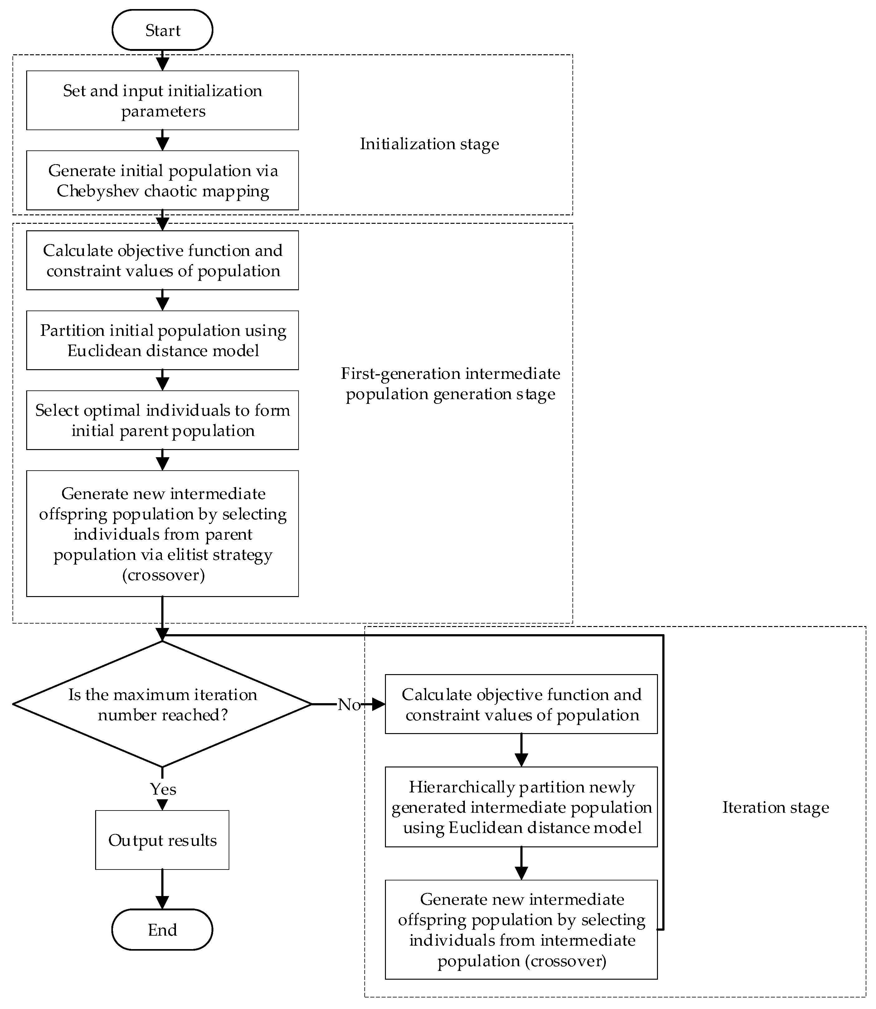
In this section, an enhanced multi-objective genetic evolutionary algorithm, designated as MO-GA, is proposed on the basis of the NSGA-II algorithm. As an enhanced variant of NSGA-II, MO-GA overcomes the issues of insufficient convergence accuracy and deteriorated search capability of NSGA-II in high-dimensional multi-objective optimization by introducing Chebyshev chaotic mapping and an elitist-strategy-based Euclidean distance model.
In contrast to single-objective optimization problems, multi-objective optimization problems often involve conflicting sub-objectives, which may preclude the existence of a single optimal solution that simultaneously satisfies all objectives. Consequently, it is necessary to continuously adjust among all sub-objectives to drive the objective functions toward the ideal optimum, ultimately yielding a compromised comprehensive optimal solution. The Non-dominated Sorting Genetic Algorithm II (NSGA-II) is recognized as an effective approach for solving multi-objective optimization problems. It is not constrained by the problem scale during the solving and iterative processes and can autonomously coordinate the relationships among objective functions, thereby producing a diverse set of solutions along the Pareto optimal front.
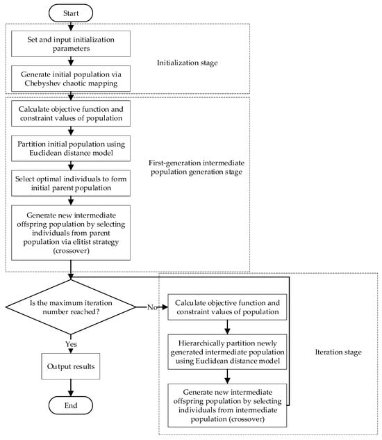
However, when applied to high-dimensional multi-objective optimization, NSGA-II lacks an adaptive population adjustment mechanism, which results in insufficient convergence accuracy and deteriorated search capability. To overcome these limitations, this paper proposes an enhanced multi-objective genetic evolutionary algorithm based on NSGA-II, referred to as the Multi-Objective Genetic Algorithm (MO-GA), to solve the established multi-objective optimization model. The proposed algorithm integrates the standard GA with NSGA-II. Specifically, a Chebyshev chaotic mapping mechanism is introduced during the population initialization stage to improve the uniformity and diversity of the initial population, thereby enabling adaptive population initialization. In the parameter optimization stage, the Euclidean distance model incorporating an elitist strategy is adopted to compute the crowding distance of the population, facilitating adaptive adjustment of the population size. This mechanism effectively alleviates the performance degradation caused by insufficient population diversity. The flowchart of the proposed MO-GA algorithm is presented in Figure 9 below.
Figure 9.
Schematic diagram of the MO-GA algorithm.
During the tuning process, the system parameters and the reference desired output are first specified to construct a canonical CFDL-MFAC controller. The parameter solution space domain is then determined. Subsequently, the Euclidean distance-based elitist strategy is adopted to partition the solution space domain and to screen the optimal solution set. Through iterative updates of the solution space domain, the Pareto optimal solutions that satisfy the multi-objective conditions are progressively sought. Finally, the solution is output according to the fitness condition of the objective function, thus accomplishing the parameter tuning optimization.
3.3. Algorithm Effectiveness Validation
3.3.1. Experimental Environment and Evaluation System Setup
In this experiment, the Hammerstein nonlinear system adopted from reference [20] is considered, and its specific form is given in Equation (17), where denotes the noise signal at the output of the controlled plant, which is typically set to zero. In addition, both the straight-line single-lane-change scenario and mixed road conditions are established. Comparative experiments are carried out among the prototype CFDL-MFAC technique, the representative method from reference [21], and the proposed approach in this paper.
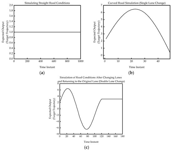
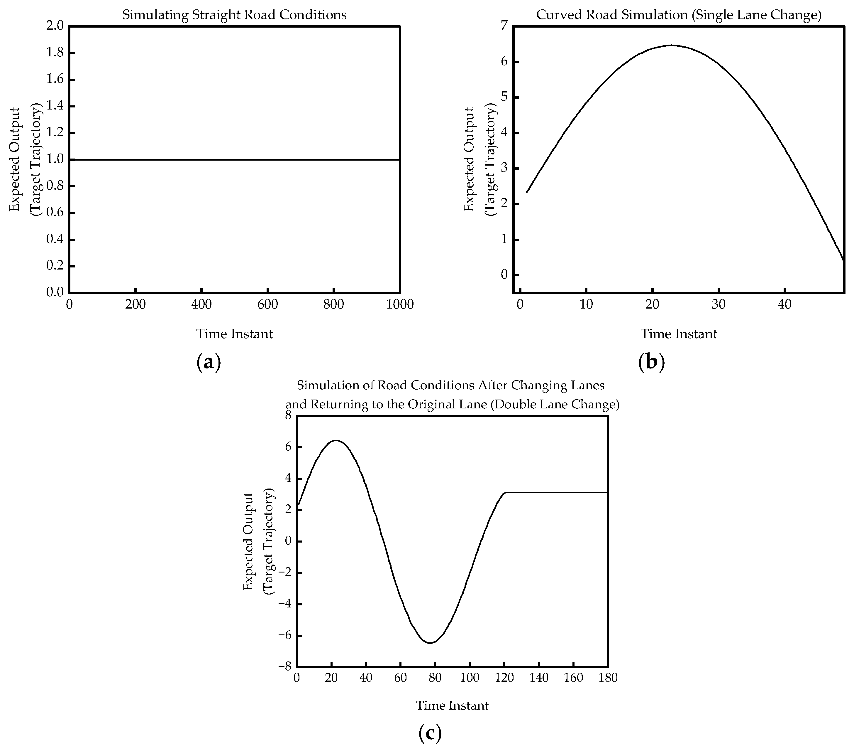
To emulate the actual operating environment of intelligent vehicles (IVs), three typical road conditions are considered in this experiment: straight road, single-lane-change (SLC), and double-lane-change (DLC), which correspond to normal driving, lane-changing for overtaking with return to the original lane, and overtaking with return to the original lane, respectively. The corresponding simulation environment is established on the MatlabR2024b platform. Figure 10 below depicts the road environment for the IVs lateral control system.
Figure 10.
Simulation of driving scenarios under different road conditions. (a) Straight road (normal driving); (b) Single-lane-change (overtaking); (c) Double-lane-change (return to original lane).
3.3.2. Experimental Results and Analysis of Effectiveness Validation
- Straight-road environment;
In the straight-road scenario, the GA-MFAC method from reference [21] and the proposed MO-GA-MFAC algorithm are first applied to derive the optimal control parameters. The initialization parameters of the standard CFDL-MFAC algorithm, as given in reference [20], are configured and listed in Table 3 below.
Table 3.
Initial parameter settings of different algorithms under straight-road environment.
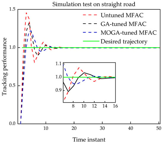
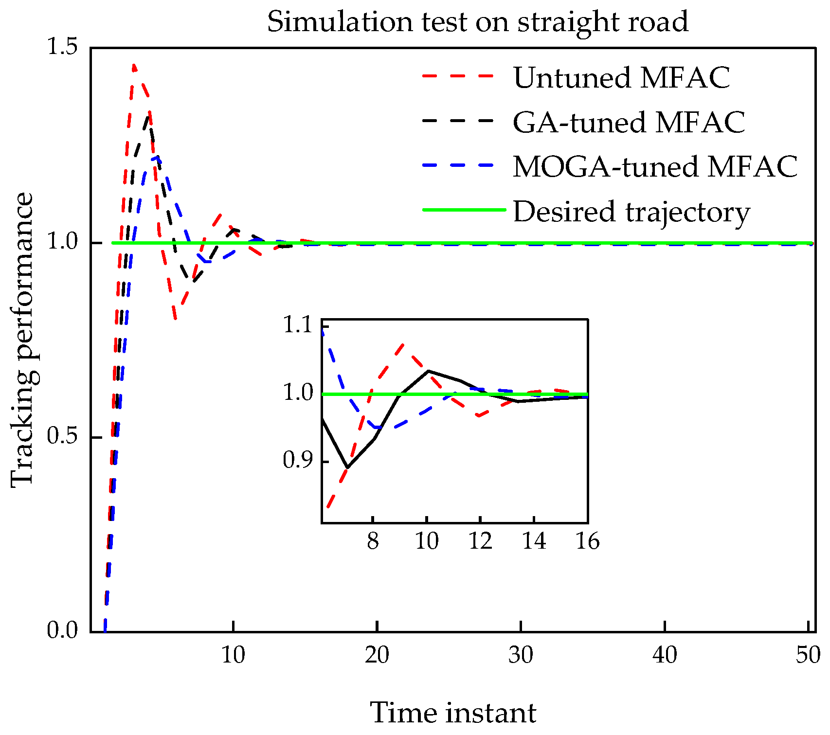
Based on the initial parameter settings listed in the above table, simulation experiments are carried out with a simulation step of . The system output versus the simulation step is plotted in Figure 11 below. Additionally, the , , , and indices are computed for the three sets of initial conditions. Since the simulated straight-road scenario corresponds to a step response of the control system, the initial value , the maximum overshoot , and the steady-state time instant are further compiled in Table 4 for additional analysis.
Figure 11.
Simulation results under straight-road environment.
Table 4.
Performance evaluation indices under straight-road environment.
From the experimental results presented in Figure 11, it is observed that the control law algorithms under all three initialization conditions are capable of tracking the desired trajectory. The data in Table 4 indicate that, in the simulated straight-road environment, the control law tuned by the proposed MO-GA-MFAC algorithm achieves certain improvements in all error indices. Specifically, compared with the prototype MFAC and GA-MFAC algorithms, the MO-GA-tuned control system reduces the index by 29.714% and 16.13%, respectively, and reduces the index by 4.67% and 25.74%, respectively. These results demonstrate that the MO-GA-tuned MFAC algorithm enables the system to track the desired trajectory with reduced tracking errors, reach steady state more rapidly, and maintain smaller output fluctuations at adjacent time instants near steady state. Thus, under straight-road conditions, its control performance is enhanced to a certain extent in comparison with the prototype MFAC and GA-MFAC.
From the system output response curves shown in Figure 11, the following characteristics can be observed. In terms of transient response, the MO-GA-MFAC scheme exhibits the fastest rise without overshoot and the earliest entry into the steady state; the GA-MFAC scheme ranks second, with a moderate overshoot but relatively fast stabilization; the prototype MFAC scheme exhibits the slowest rise, the largest overshoot, and the longest time to enter the steady state. In terms of steady-state response, the MO-GA-MFAC scheme exhibits the smallest output fluctuations after entering the steady state, with the smoothest curve; the GA-MFAC scheme ranks second; and the prototype MFAC scheme exhibits the largest steady-state fluctuations. These observations indicate that the MO-GA-MFAC tuning scheme outperforms the two benchmark schemes in terms of response speed, dynamic smoothness, and steady-state accuracy.
- 2.
- Curved-road (SLC) environment;
In the single-lane-change scenario, the GA-MFAC method from reference [21] and the proposed MO-GA-MFAC algorithm are first applied to derive the optimal control parameters. The initialization parameters of the standard CFDL-MFAC algorithm, as given in reference [20], are configured and listed in Table 5 below.
Table 5.
Initial parameter settings of different algorithms under simulated SLC environment.
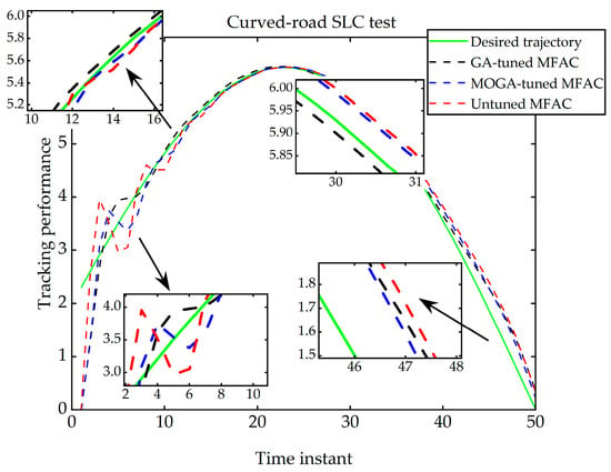
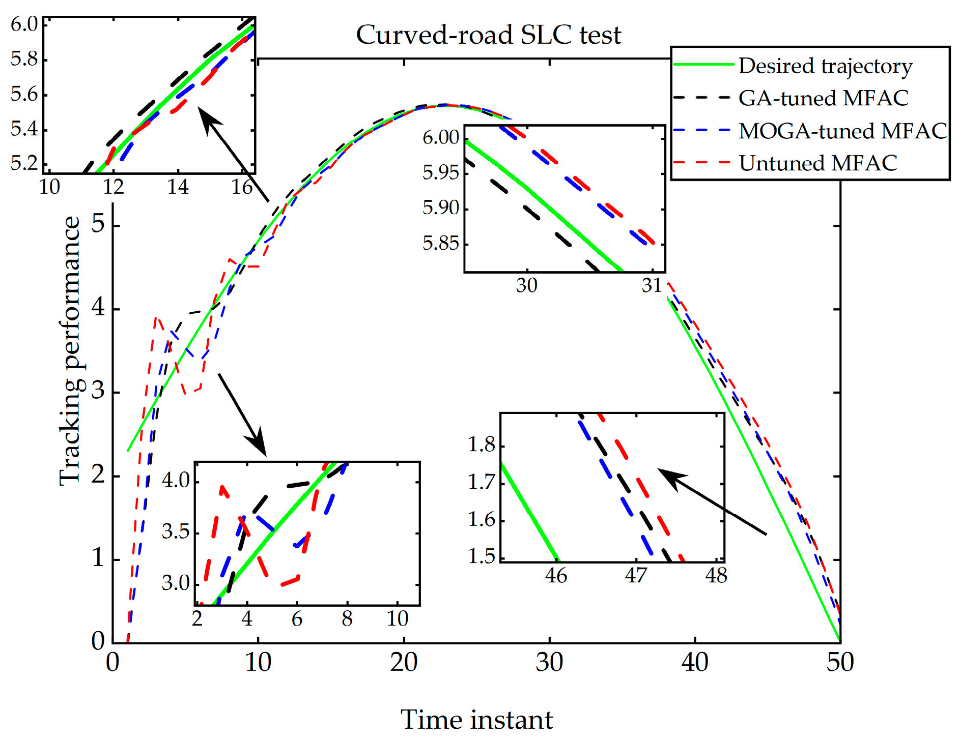
Based on the initial parameter settings listed in the above table, simulation experiments are carried out with a simulation step of , and the results are presented in Figure 12 below. The , , , and indices are computed for the three sets of initial conditions and summarized in Table 6.
Figure 12.
Simulation results under SLC environment.
Table 6.
Performance evaluation indices under SLC environment.
From the experimental results presented in Figure 12, it is observed that the control law algorithms under all three initialization conditions are capable of tracking the desired trajectory. In terms of output oscillation, the proposed MO-GA-MFAC algorithm exhibits a smoother response, allowing the system to resume tracking more quickly after transient oscillations. Compared with the GA-MFAC-tuned algorithm from reference [8], the latter achieves more accurate tracking during the intermediate stage, while the MO-GA-tuned system offers the advantage of a closer initial output to the desired value in the latter stage of control. The data in Table 6 indicate that, in the simulated single-lane-change scenario, the control law tuned by the proposed MO-GA algorithm achieves substantial improvements across all error indices. Specifically, compared with the prototype MFAC and GA-MFAC algorithms, the MO-GA-tuned control system reduces the index by 64.22% and 47.44%, respectively, and reduces the index by 86.52% and 78.9%, respectively. These results demonstrate that the MO-GA-tuned algorithm enables the system to track the desired trajectory with significantly reduced errors, reach steady state more rapidly, and maintain smaller output fluctuations near steady state, thereby exhibiting favorable control stability.
From the system output response curves shown in Figure 12, the following characteristics can be observed. In terms of transient response, all three schemes exhibit certain oscillations at the initial stage, but the MO-GA-MFAC scheme recovers most rapidly after the oscillations and resumes tracking of the desired trajectory more quickly; the GA-MFAC scheme ranks second; and the prototype MFAC scheme exhibits the slowest recovery and the longest oscillation duration. In terms of steady-state response, after entering the latter stage of the control process, the MO-GA-MFAC scheme exhibits the smallest and smoothest output fluctuations, with the curve closer to the desired value; the GA-MFAC scheme performs well during the intermediate stage but exhibits slightly larger fluctuations in the latter stage compared with the MO-GA-MFAC scheme; and the prototype MFAC scheme exhibits the largest steady-state fluctuations. These observations indicate that the MO-GA-MFAC algorithm offers superior recovery capability and steady-state tracking accuracy after transient disturbances.
- 3.
- Curved-road (DLC) environment;
In the double-lane-change scenario, the GA-MFAC method from reference [21] and the proposed MO-GA-MFAC algorithm are first applied to derive the optimal control parameters. The initialization parameters of the standard CFDL-MFAC algorithm, as given in reference [20], are configured and listed in Table 7 below.
Table 7.
Initial parameter settings of different algorithms under simulated DLC environment.
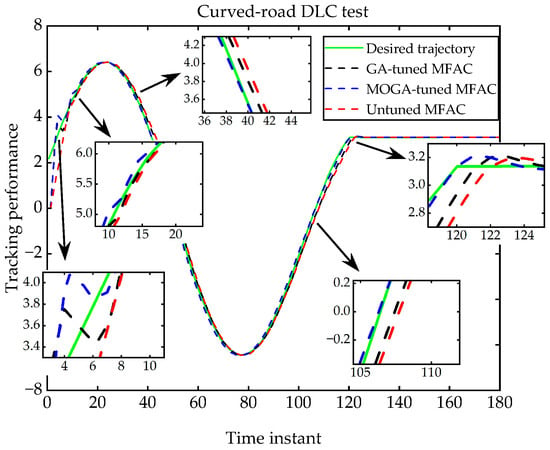
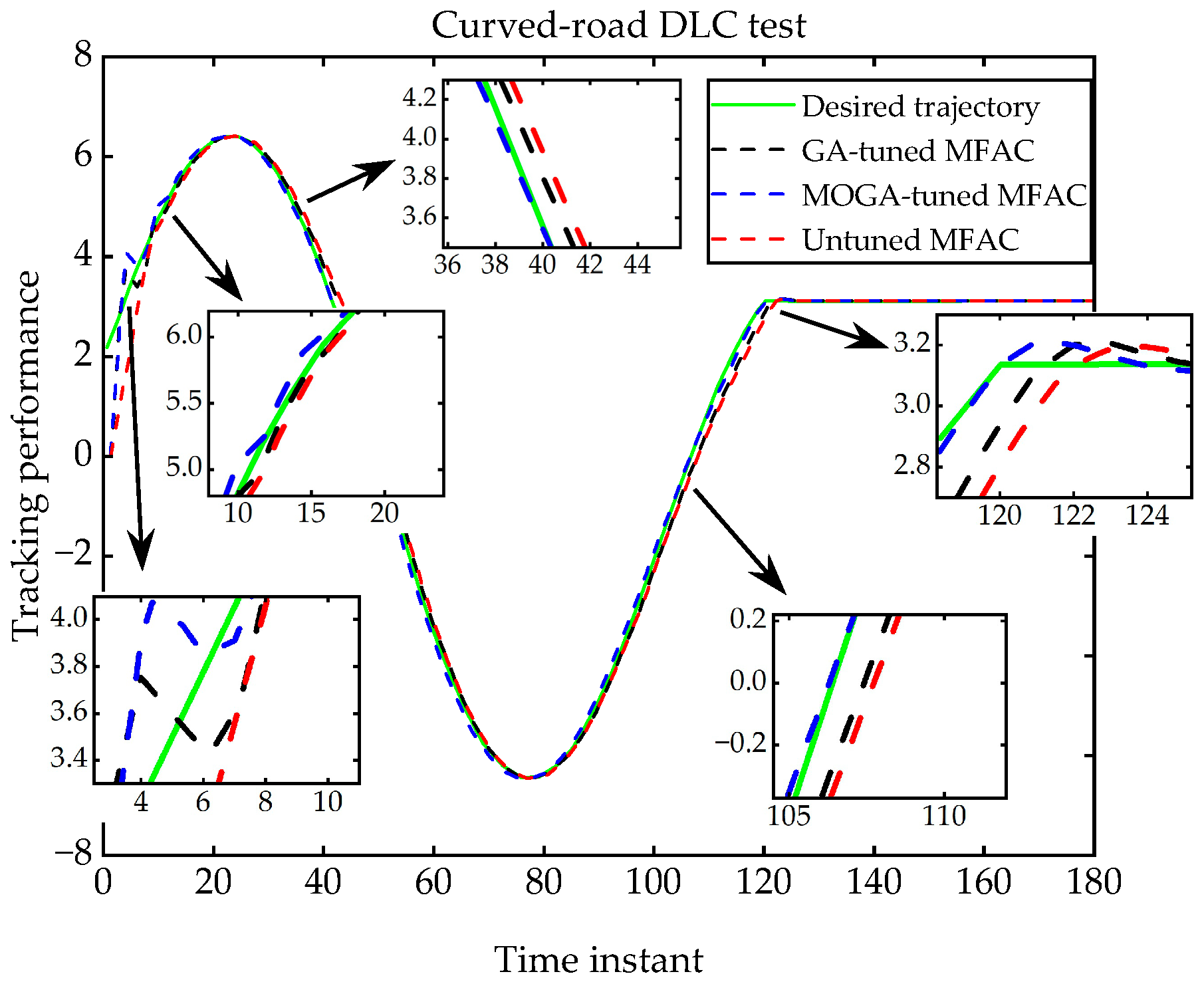
Based on the initial parameter settings listed in the above table, simulation experiments are carried out with a simulation step of , and the results are presented in Figure 13 below. The , , , and indices are computed for the three sets of initial conditions and summarized in Table 8.
Figure 13.
Simulation results under DLC environment.
Table 8.
Performance evaluation indices under DLC environment.
From the experimental results presented in Figure 13, it is observed that the control law algorithms under all three initialization conditions are capable of tracking the desired trajectory. In terms of output oscillation, the proposed MO-GA-MFAC algorithm exhibits a slightly higher maximum amplitude than the GA-MFAC algorithm; nevertheless, it is able to resume tracking more rapidly and accurately after transient oscillations. Compared with the GA-MFAC-tuned algorithm from reference [12], the MO-GA-MFAC achieves more accurate tracking throughout the entire control process, with an initial output closer to the desired value.
The data in Table 8 indicate that, in the simulated double-lane-change scenario, the control law tuned by the proposed MO-GA-MFAC algorithm achieves substantial improvements across all error indices. Specifically, compared with the prototype MFAC and GA-MFAC algorithms, the MO-GA-MFAC-tuned control system reduces the index by 59.052% and 41.73%, respectively, and reduces the index by 85.62% and 70.414%, respectively. These results demonstrate that the MO-GA-MFAC-tuned algorithm enables the system to track the desired trajectory with significantly reduced errors, reach steady state more rapidly, and maintain smaller output fluctuations near steady state, thereby exhibiting favorable control stability.
From the system output response curves shown in Figure 13, the following characteristics can be observed. In terms of transient response, the MO-GA-MFAC scheme responds rapidly to changes in the desired trajectory throughout the entire control process, with the smallest overshoot and the fastest convergence; the GA-MFAC scheme ranks second; and the prototype MFAC scheme exhibits the most sluggish response, the largest overshoot, and the most pronounced tracking delay at trajectory change points. In terms of steady-state response, the MO-GA-MFAC scheme exhibits the smallest and smoothest output fluctuations after entering the steady state, with the smallest deviation from the desired value; the GA-MFAC scheme ranks second; and the prototype MFAC scheme exhibits the largest steady-state fluctuations. As the most challenging road scenario, the double-lane-change case demonstrates that the MO-GA-MFAC algorithm maintains favorable transient and steady-state control performance even under complex operating conditions.
4. Results and Discussion
4.1. Simulation Experiment of MFAC Control Scheme for Audi A6-Avan
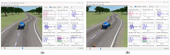
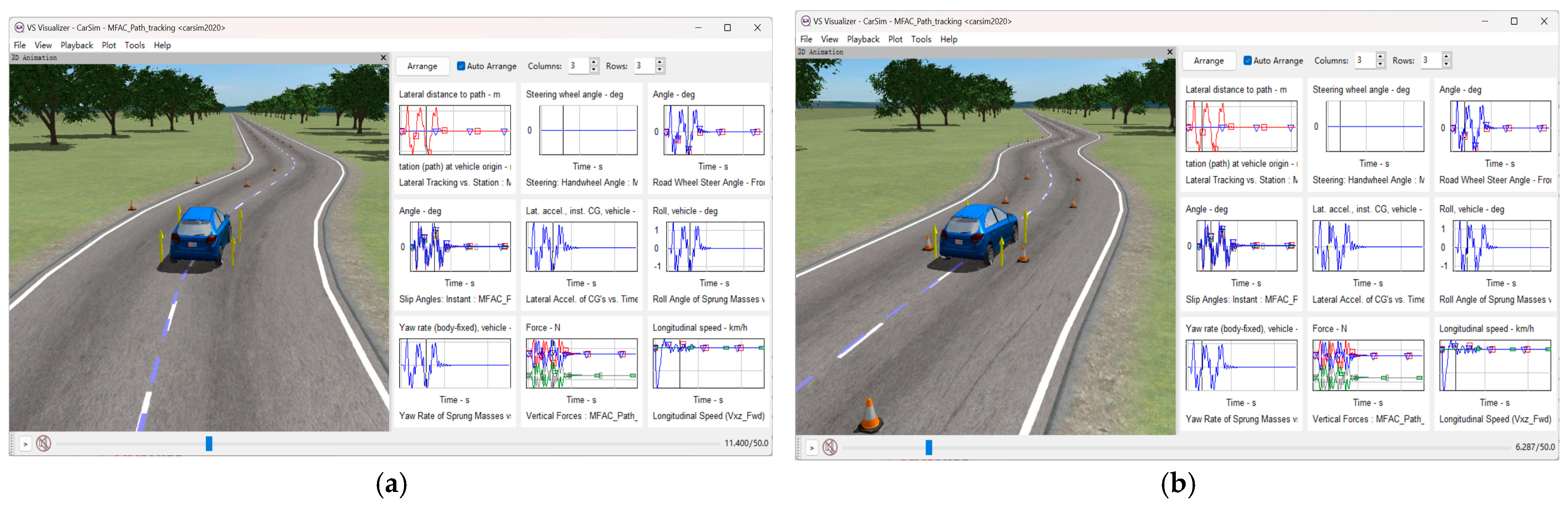
In real-world driving scenarios, the continuous slalom maneuver serves as a comprehensive test of the vehicle’s obstacle avoidance capability and steering accuracy. Since such maneuvers are typically performed at relatively low speeds, the simulation in this experiment is conducted at a vehicle speed of km/h. Two random time instants are selected from the dynamic simulation video of the Audi A6-Avant tracking the slalom trajectory on the Carsim2020 platform, and the corresponding snapshots of the vehicle motion are presented in Figure 14 below.
Figure 14.
Real-time snapshots of Audi A6-Avant slalom tracking at 30 km/h. (a) At 11.4 s; (b) At 6.287 s.
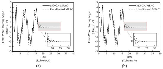
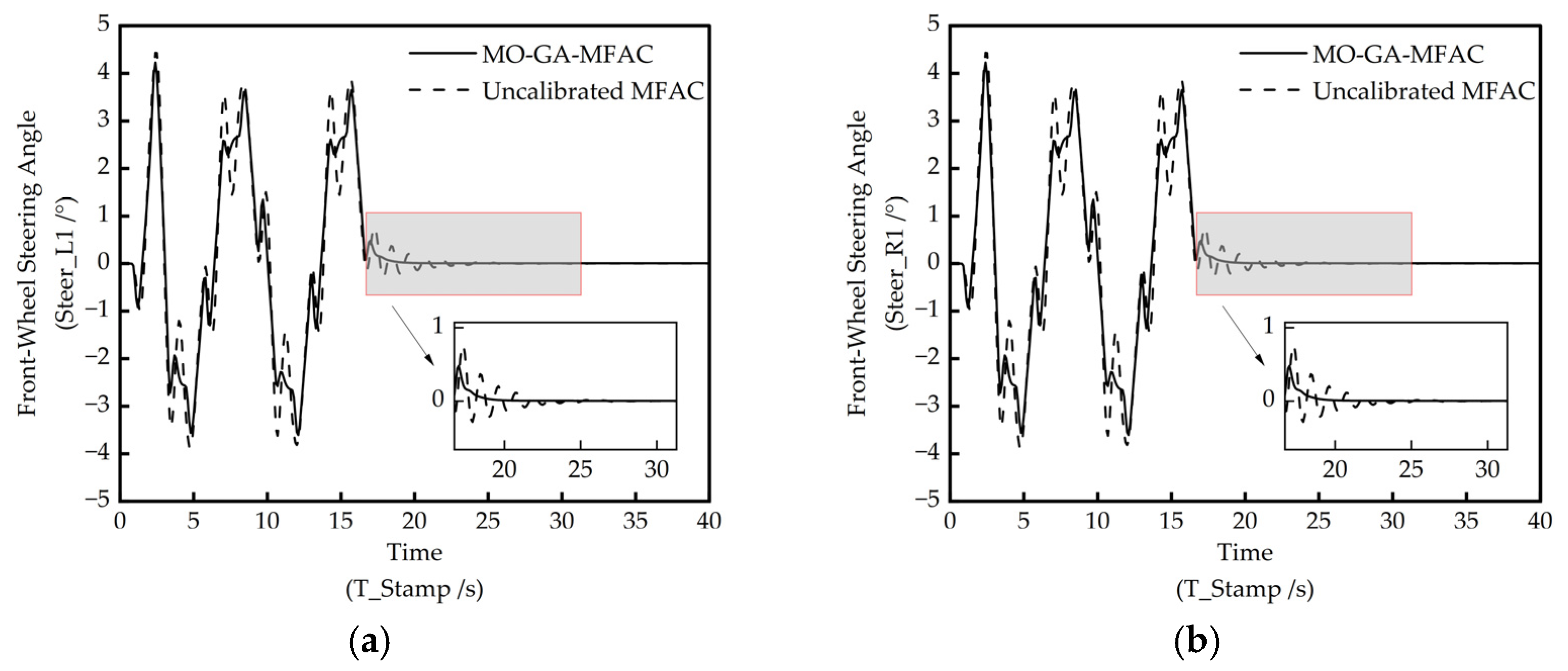
From the experimental results presented in Figure 15, it is observed that the control system achieves effective tracking of the slalom road under the given road conditions. To further evaluate the control performance, the time histories of the left and right front wheel steering angles are plotted for both the untuned MFAC and the MO-GA-tuned MFAC schemes, as shown in Figure 15 below, to verify the tracking performance.
Figure 15.
Left and right front wheel steering angles of Audi A6-Avant under slalom trajectory. (a) Left front wheel angle; (b) Right front wheel angle.
From Figure 15, it is observed that during the vehicle’s tracking of the continuous slalom maneuver, both control schemes result in certain abrupt changes in the left and right front wheel steering angles. Specifically, the untuned MFAC control produces more oscillatory fluctuations and abrupt variations in the steering angles compared with the tuned MFAC. When the vehicle completes the slalom maneuver and transitions to straight-line driving, the wheel steering angles under the tuned MFAC control exhibit no noticeable fluctuations, indicating a smooth transition. In contrast, the untuned MFAC control still exhibits steering angle fluctuations during this phase and requires a certain time to reach convergence. These results confirm that both schemes are capable of enabling the Audi A6-Avant (C-Class model) to accomplish slalom tracking; however, the MO-GA-MFAC scheme offers superior driving stability.
4.2. Longitudinal Simulation Experiment on Audi A6-Avant
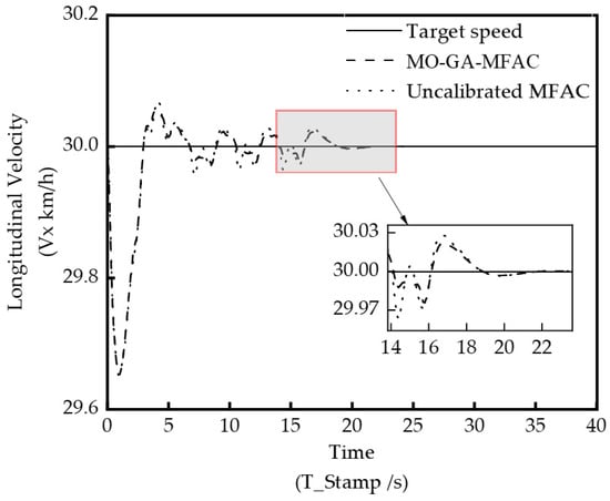
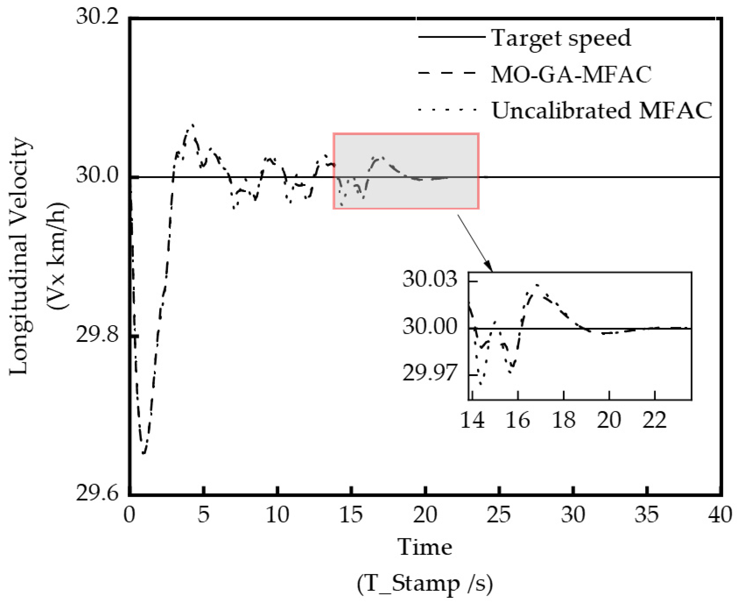
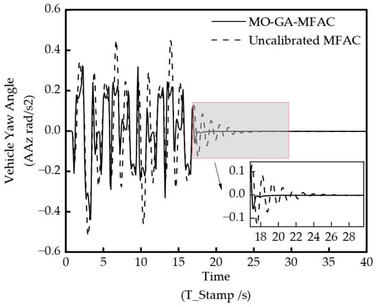
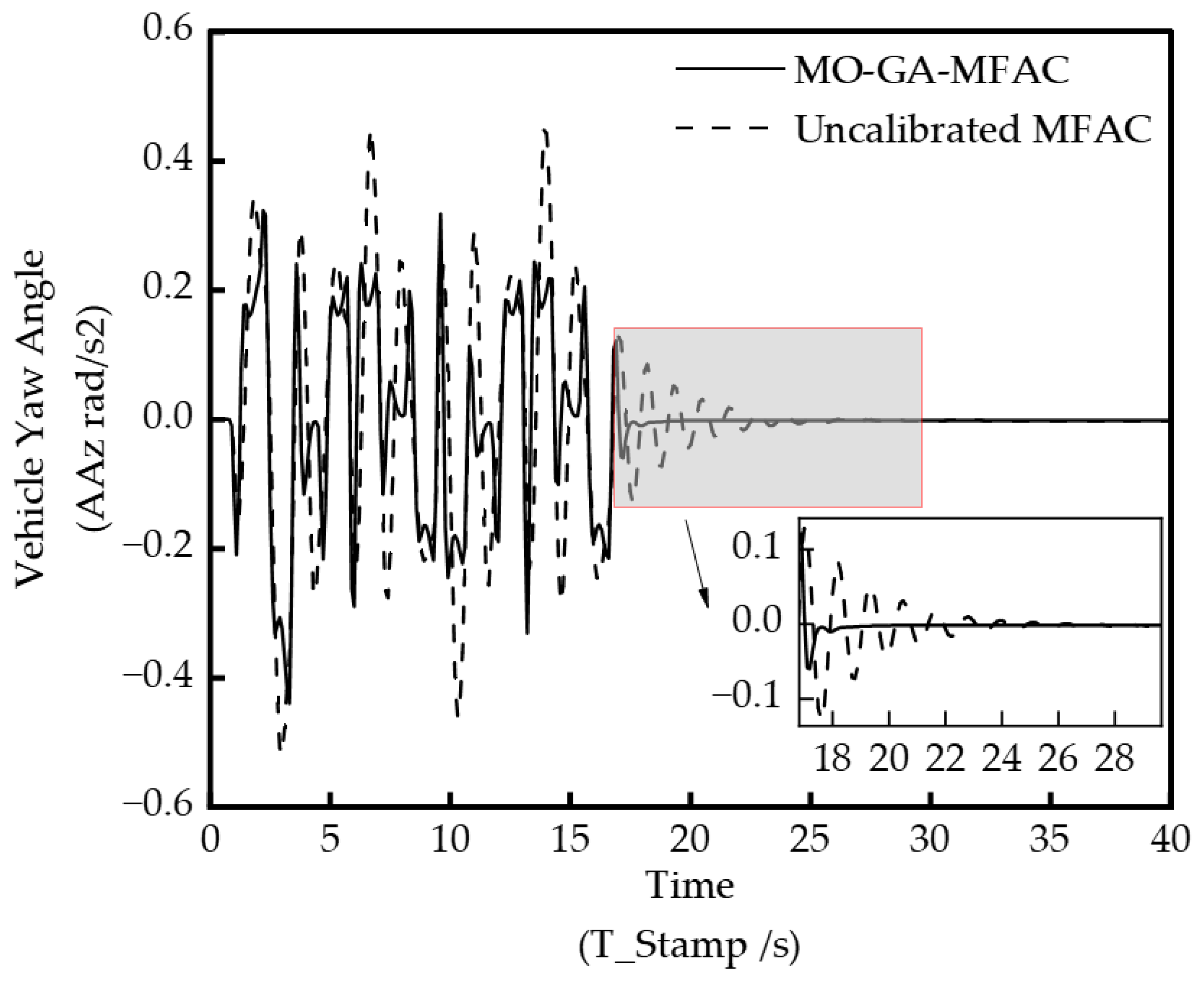
To further validate the proposed approach from the perspectives of vehicle ride comfort and passenger comfort, on the basis of the above study, the time histories of the vehicle longitudinal velocity and yaw angle are plotted and analyzed. The corresponding experimental results are presented in Figure 16 and Figure 17 below.
Figure 16.
Time history of longitudinal velocity of Audi A6-Avant under slalom trajectory.
Figure 17.
Time history of yaw angle of Audi A6-Avant under slalom trajectory.
From the time history of longitudinal velocity during trajectory tracking shown in Figure 17, it is observed that both the untuned MFAC and the MO-GA-tuned MFAC exhibit relatively large error fluctuations within an acceptable range at the initial stage. This is attributed to the inherent system delay at the beginning of the co-simulation. After the system reaches stable operation, both MFAC schemes are capable of maintaining the target speed within a very small error margin while tracking the slalom trajectory, with no abrupt speed variations, indicating satisfactory ride comfort. Furthermore, the speed error fluctuations of the MO-GA-tuned algorithm are smaller and smoother, and it converges to the target value more rapidly. This confirms that the proposed approach offers enhanced driving stability and ride comfort.
From the time history of the yaw angle during trajectory tracking shown in Figure 17, it is observed that the yaw angle values of both the untuned MFAC and the MO-GA-tuned MFAC remain relatively small throughout the entire slalom tracking process. During obstacle avoidance or cornering, performance differences between the two control schemes become evident. In terms of both peak yaw angle and fluctuation magnitude, the MO-GA-tuned MFAC exhibits smaller peaks at multiple time instants, with reduced and smoother fluctuations compared with the untuned MFAC. Although abrupt changes in the yaw angle peaks occur at certain instants—typically at the points of maximum curvature of the slalom path—the system is capable of real-time adjustment within a short subsequent period. During the transition from slalom maneuvering to straight-line driving along the lane, the yaw angle response under the MO-GA-tuned MFAC is smooth and free of oscillations, enabling faster adaptation to changing road conditions and thereby offering improved ride comfort and overall passenger experience.
5. Conclusions
This paper has proposed a parameter tuning algorithm for the model-free adaptive control (MFAC) method. Based on the four key initialization parameters of the MFAC algorithm, the proposed scheme integrates parameter sensitivity analysis and multi-objective optimization model transformation to enhance the control accuracy of the standard MFAC algorithm, while reducing control oscillations and settling time. The effectiveness and portability of the proposed algorithm have been systematically validated through extensive simulation experiments.
In the straight-road scenario, the MO-GA-MFAC-tuned control system reduces the index by 29.714% and 16.13%, and the index by 4.67% and 25.74%, respectively, compared with the prototype MFAC and GA-MFAC. The settling time is shortened from 30 steps to 22 steps, indicating faster response and superior steady-state performance. In the single-lane-change scenario, the index is reduced by 64.22% and 47.44%, and the index is reduced by 86.52% and 78.9%, respectively, demonstrating particularly significant improvements in tracking accuracy under transient maneuvering conditions. In the double-lane-change scenario, the index is reduced by 59.052% and 41.73%, and the index is reduced by 85.62% and 70.414%, respectively. Furthermore, in the slalom maneuver validation conducted on the CarSim-MATLAB co-simulation platform with the Audi A6-Avant model, the MO-GA-MFAC-tuned control strategy exhibits superior driving stability, as evidenced by smaller fluctuations in the front wheel steering angles, faster convergence of longitudinal velocity errors, and smoother yaw angle trajectories, thereby confirming its effectiveness in enhancing both ride comfort and passenger experience.
In summary, the proposed algorithm is well-suited for lateral trajectory tracking control of intelligent vehicles and exhibits favorable model adaptability, as demonstrated by its consistent performance across three distinct nonlinear systems (H1, H2, H3) and three road conditions (straight road, single-lane-change, and double-lane-change). Nevertheless, the sensitivity analysis in this study is conducted using the factor perturbation method, which does not account for the interaction effects among parameters. Future work should therefore focus on investigating these parameter interactions to further refine the tuning strategy and extend its applicability to more complex driving scenarios.
Author Contributions
Conceptualization, D.W. and Y.X.; methodology, D.W.; software, D.W.; validation, D.W., Y.X. and J.Y.; formal analysis, D.W.; investigation, D.W.; resources, D.W.; data curation, D.W.; writing—original draft preparation, D.W.; writing—review and editing, Y.X.; visualization, Y.X.; supervision, D.W.; project administration, D.W.; funding acquisition, D.W. All authors have read and agreed to the published version of the manuscript.
Funding
This research was funded by [National Natural Science Foundation of China] grant number [32072498].
Data Availability Statement
The original contributions presented in this study are included in the article. Further inquiries can be directed to the corresponding author.
Conflicts of Interest
All authors declare that the research was conducted in the absence of any commercial or financial relationships that could be construed as potential conflicts of interest.
Appendix A
Figure A1.
Line charts of the evaluation indices with respect to the parameters of system H1 under a 5% rate of change. (a) Parameter ; (b) Parameter ; (c) Parameter ; (d) Parameter .
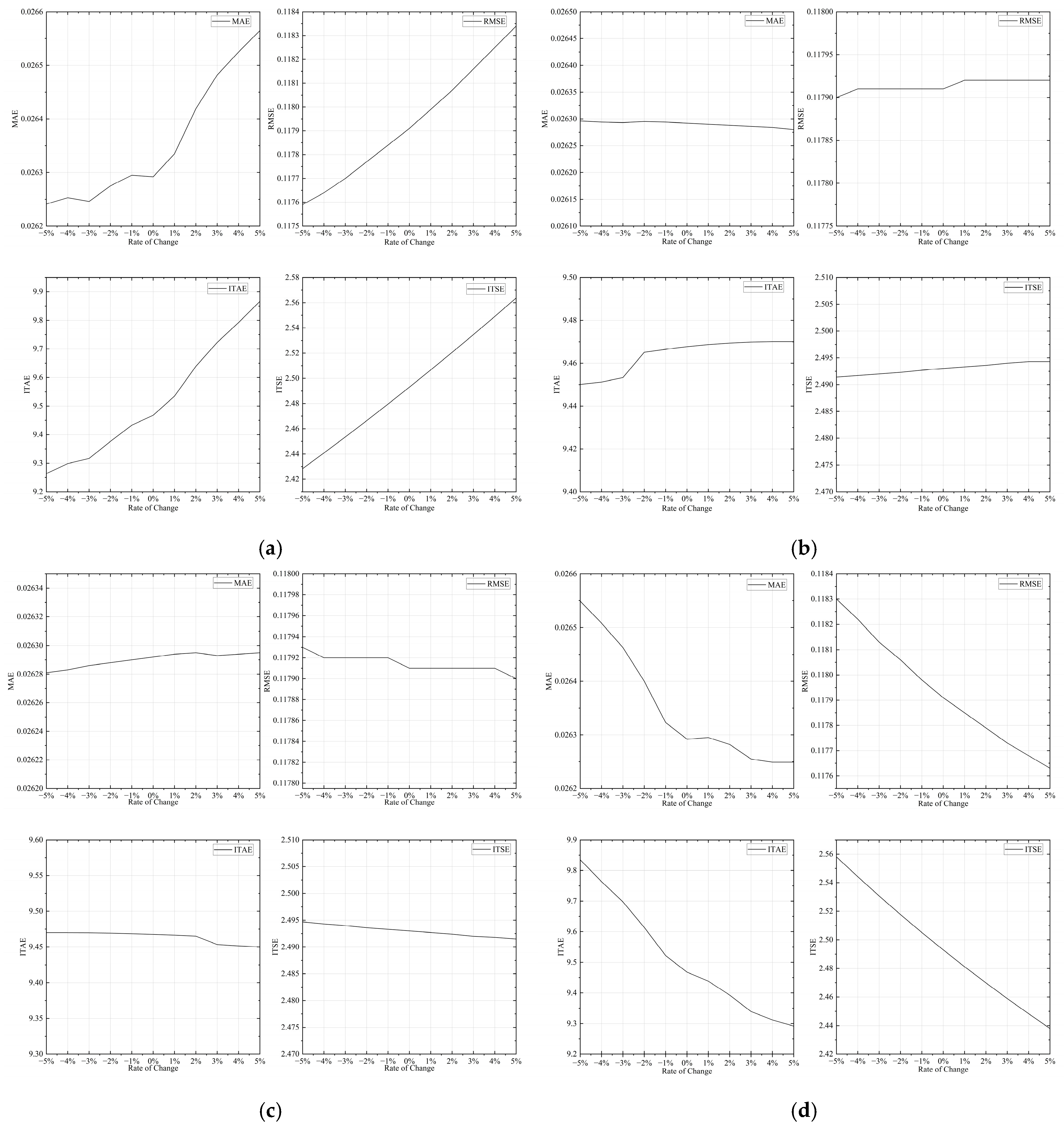
Figure A2.
Line charts of the evaluation indices with respect to the parameters of system H2 under a 5% rate of change. (a) Parameter ; (b) Parameter ; (c) Parameter ; (d) Parameter .
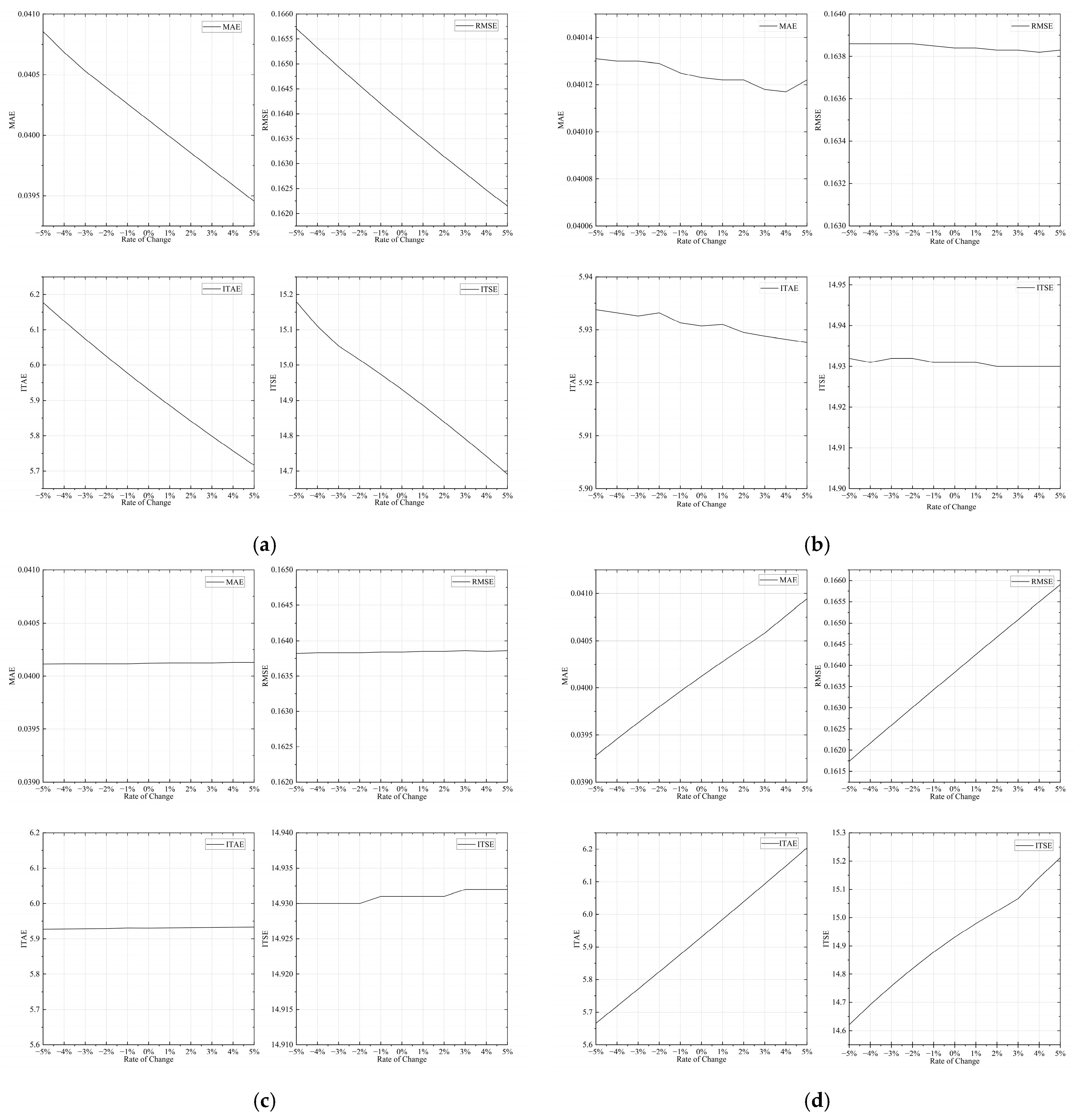
Figure A3.
Line charts of the evaluation indices with respect to the parameters of system H3 under a 5% rate of change. (a) Parameter ; (b) Parameter ; (c) Parameter ; (d) Parameter .
References
- Han, G.; Fu, W.; Wang, W.; Wu, Z. The lateral tracking control for the intelligent vehicle based on adaptive PID neural network. Sensors 2017, 17, 1244. [Google Scholar] [CrossRef] [Scilit] [PubMed]
- Wu, J.; Wang, Z.; Zhang, L. Unbiased-estimation-based and computation-efficient adaptive MPC for four-wheel-independently-actuated electric vehicles. Mech. Mach. Theory 2020, 154, 104100. [Google Scholar] [CrossRef] [Scilit]
- Zhang, X.; Zhu, X. Autonomous path tracking control of intelligent electric vehicles based on lane detection and optimal preview method. Expert Syst. Appl. 2019, 121, 38–48. [Google Scholar] [CrossRef] [Scilit]
- Wang, K.; Li, Q.; Wang, Z.; Yang, J. Trajectory tracking control for automated vehicle based on NMPC considering vehicle rolling motion. Control Decis. 2022, 37, 2535–2542. [Google Scholar]
- Lu, X.; Xing, Y.; Guirong, Z.; Bo, L.; Renxie, Z. Review on Motion Control of Autonomous Vehicles. J. Mech. Eng. 2020, 56, 127–143. [Google Scholar] [CrossRef] [Scilit]
- Yao, Q.; Tian, Y.; Wang, Q.; Wang, S. Control Strategies on Path Tracking for Autonomous Vehicle: State of the Art and Future Challenges. IEEE Access 2020, 8, 161211–161222. [Google Scholar] [CrossRef] [Scilit]
- Xiong, L.; Yang, X.; Zhuo, G.; Leng, B.; Zhang, R. A Review of the Current Status of Motion Control Development for Autonomous Vehicles. J. Mech. Eng. 2020, 56, 127–143. [Google Scholar]
- Liu, G.; Hou, Z. Quantized Data Driven Model-Free Adaptive Predictive Control for a Class of Nonlinear Systems. In 2023 IEEE 12th Data Driven Control and Learning Systems Conference (DDCLS); IEEE: New York, NY, USA, 2023; pp. 1105–1110. [Google Scholar]
- Hou, Z.; Xu, J. A Review and Perspective on Data-Driven Control Theory and Methods. J. Autom. 2009, 35, 650–667. [Google Scholar]
- Hou, Z. Current status and perspectives of model-free adaptive control. Control Theory Appl. 2006, 586–592. [Google Scholar]
- Tian, T.; Hou, Z.; Liu, S.; Deng, Z. A lateral control method for driverless cars based on model-free adaptive control. J. Autom. 2017, 43, 1931–1940. [Google Scholar]
- Chen, J.; Zhao, W.; Zhou, W.; Yan, D. Improvements to the Model-Free Adaptive Control of a Sanitation Vehicle Trajectory Tracking System. Automot. Electr. Syst. 2025, 9, 13+17. [Google Scholar]
- Zhou, L.; Xia, J.; Li, Z. Improved Model-Free Adaptive Control of Speed Tracking System for EMUs. J. Transp. Eng. 2024, 24, 267–280. [Google Scholar]
- Liu, K.; Chen, J. An improved model-free adaptive control optimisation method. J. Beijing Univ. Chem. Technol. (Nat. Sci. Ed.) 2023, 50, 66–73. [Google Scholar]
- Li, R.; Zhu, Z. Improved Artificial Bee Colony Algorithm in MFAC Parameter Tuning. Autom. Instrum. 2016, 37, 75–79+83. [Google Scholar]
- Song, Z.; Li, G.; Liu, L. A new parameter tuning method for model-free adaptive control models. J. Chem. Eng. 2019, 70, 3430–3440. [Google Scholar]
- Wang, H.; Li, T. Research on MFAC control based on hybrid krill swarm intelligent algorithm. J. Chongqing Univ. Technol. (Nat. Sci.) 2020, 34, 185–191. [Google Scholar]
- Shao, Y.; Chen, Y. Design of a Lateral Fuzz Controller for Autonomous Vehicles. J. Chongqing Jiaotong Univ. (Nat. Sci. Ed.) 2019, 38, 7–13. [Google Scholar]
- Zhou, L.; Yu, X. Analysis of Control Methods for Intelligent Vehicle Autonomous Driving. Times Automob. 2022, 180–181. [Google Scholar]
- Yu, X.; Chen, T. Distributed iterative learning control of nonlinear multiagent systems using controller-based dynamic linearization method. IEEE Trans. Cybern. 2023, 54, 4489–4501. [Google Scholar] [CrossRef] [Scilit] [PubMed]
- Wang, C.; Liu, D.; Wei, Q.; Zhao, D.; Xia, Z. Iterative adaptive dynamic programming approach to power optimal control for smart grid with energy storage devices. Acta Autom. Sin. 2014, 40, 1984–1990. [Google Scholar]

Disclaimer/Publisher’s Note: The statements, opinions and data contained in all publications are solely those of the individual author(s) and contributor(s) and not of MDPI and/or the editor(s). MDPI and/or the editor(s) disclaim responsibility for any injury to people or property resulting from any ideas, methods, instructions or products referred to in the content. |
© 2026 by the authors. Published by MDPI on behalf of the World Electric Vehicle Association. Licensee MDPI, Basel, Switzerland. This article is an open access article distributed under the terms and conditions of the Creative Commons Attribution (CC BY) license.