


Highlights
- A differential flatness-based nonlinear controller is developed for PEMFC-fed interleaved boost converters.
- Cascade energy and current regulation is implemented for EV power conversion applications.
- Multiphase interleaving operation effectively reduces fuel cell input current ripple.
- Experimental validation confirms stable operation, robust voltage regulation, and fast transient response.
- Improved dynamic performance is demonstrated compared with a conventional PI controller.
What are the main findings?
- The proposed differential flatness-based controller achieved stable DC bus voltage regulation with improved transient response under dynamic operating conditions.
- The interleaved boost converter reduced fuel cell input current ripple while maintaining balanced current sharing between converter phases during experimental validation.
What are the implications of the main findings?
- The proposed control strategy can improve the dynamic performance and operational reliability of PEMFC-based EV power conversion systems.
- Reduced current ripple and improved transient regulation may help decrease electrical stress on the fuel cell stack and potentially extend PEMFC operational lifetime.
Abstract
Proton exchange membrane fuel cell (PEMFC) systems typically generate low-voltage and high-current DC power, requiring a step-up converter interface for electric vehicle (EV) and DC microgrid applications. In addition, excessive current ripple and rapid transient loading conditions may increase electrical and thermal stress within the fuel cell stack. Consequently, both converter topology and control strategy play important roles in maintaining stable system operation and favorable PEMFC operating conditions. This paper presents a differential flatness-based nonlinear control strategy for a PEMFC-fed multiphase interleaved boost converter. The proposed control structure combines inner-loop inductor current regulation with outer-loop DC bus energy regulation. This configuration achieves stable voltage control, balanced phase-current sharing, and reduced fuel cell current ripple during transient operating conditions. A two-phase interleaved boost converter prototype was experimentally implemented using a 2.5 kW PEMFC platform and a dSPACE DS1202 MicroLabBox real-time controller. Experimental tests under steady-state and dynamic loading conditions were conducted to evaluate DC bus voltage regulation, transient response, current-sharing capability, and robustness against load disturbances. The experimental results demonstrated that the proposed nonlinear controller achieved faster transient voltage recovery and smaller DC bus voltage deviation compared with a conventional PI-based control approach. In addition, the interleaved converter structure reduced input current ripple at the PEMFC output terminals during dynamic operation. Overall, the results indicate that the proposed control strategy is suitable for PEMFC-powered EV and DC microgrid applications requiring stable DC bus regulation and fast dynamic power control. Experimental results demonstrate that the proposed controller reduces the DC bus voltage recovery time from approximately 150 ms to 50 ms, corresponding to a 66.7% improvement over a conventionally tuned PI controller. In addition, the maximum DC bus voltage deviation is reduced from approximately 1.0 V to 0.5 V while maintaining balanced phase-current sharing with less than 3% mismatch throughout the tested operating conditions.
1. Introduction
Battery-electric vehicle (EV) platforms still face practical limitations related to driving range, charging time, and energy sustainability, particularly in heavy-duty and long-distance transportation applications [1,2]. Consequently, hydrogen fuel cell-based powertrains have attracted increasing attention as alternative onboard power sources for next-generation EVs [3,4]. Among various fuel cell technologies, proton exchange membrane fuel cells (PEMFCs) are widely regarded as one of the most suitable candidates for EV applications because of their relatively low operating temperature, high power density, and rapid start-up capability compared with solid oxide and molten carbonate fuel cells [5,6]. In practical EV operation, PEMFC systems are particularly suitable for EV applications characterized by rapid load fluctuations and frequent acceleration events. Unlike electrochemical batteries, PEMFCs can continuously supply electrical energy as long as hydrogen fuel and oxidant are adequately provided to the stack [7,8].
Despite these advantages, PEMFC systems generally exhibit low output voltage and high output current characteristics, especially during medium- and high-power operation. Therefore, a high step-up DC–DC converter is typically required to interface the fuel cell stack with the high-voltage DC bus used in EV traction systems or DC microgrids. In addition, PEMFC systems are particularly sensitive to excessive current ripple, which may accelerate membrane degradation, increase thermal stress, and shorten stack lifetime [9,10,11,12]. Previous experimental studies have reported that low-frequency ripple current can contribute to membrane hydration imbalance and unstable electrochemical behavior during dynamic load operation. Consequently, both converter topology and control strategy directly influence PEMFC operating stress and long-term system reliability [9,10,11].
Among various high step-up converter structures, the interleaved boost converter has been widely adopted in PEMFC applications because of its distributed current characteristics and ripple reduction capability. In our preliminary hardware experiments, the interleaved structure also reduced localized thermal stress in the switching devices compared with the conventional single-phase boost converter. By introducing phase-shifted operation between converter branches, partial cancelation of the input current ripple can be achieved [13]. In practical fuel cell systems, reducing low-frequency ripple current is particularly important because ripple propagation into the PEMFC stack can negatively affect fuel utilization dynamics and electrochemical stability during rapid load transitions [14]. During our experimental observations, excessive ripple current also increased fluctuations in the PEMFC output current during abrupt load changes.
Besides hardware configuration, converter control significantly affects system stability, transient response, and current-sharing accuracy between converter phases [15,16,17]. Conventional PI-based cascade control is widely implemented in commercial converter platforms because of its simplicity and ease of implementation [18]. However, controller retuning is often required when the operating point changes significantly. In most cases, PI controllers are designed using small-signal linearized models around a nominal operating point. Under large load variations and nonlinear converter behavior, controller performance may deteriorate significantly. This issue becomes increasingly important during sudden traction load variations and regenerative braking events in EV applications.
To improve large-signal transient performance, several nonlinear control approaches have recently been investigated for fuel cell converter systems. Representative nonlinear control techniques include sliding mode control (SMC), model predictive control (MPC), adaptive control, and H∞ control. Sliding mode control provides excellent robustness against parameter uncertainties but may introduce chattering effects. Model predictive control offers superior dynamic performance at the expense of higher computational complexity due to online optimization. Adaptive and H∞ controllers improve robustness under uncertain operating conditions; however, they generally require more complicated controller synthesis and parameter tuning than differential flatness-based approaches. Nevertheless, many reported nonlinear methods require accurate parameter estimation, complicated coordinate transformations, or computationally intensive optimization algorithms that may not be suitable for real-time embedded implementation. In comparison with optimization-based nonlinear control methods, differential flatness theory provides a more compact control formulation with lower computational burden, making it attractive for embedded converter applications subjected to fast transient conditions [19,20,21]. As a result, the proposed controller can preserve the inherent nonlinear dynamics of the converter while maintaining relatively low implementation complexity.
Compared with other nonlinear control strategies, such as sliding mode control, model predictive control, and adaptive control, differential flatness provides an explicit analytical control law without requiring online optimization or discontinuous switching actions. These characteristics make it particularly suitable for PEMFC-fed interleaved boost converters, where fast transient response, low computational burden, and smooth control actions are essential for reducing input current ripple, maintaining current-sharing balance, and mitigating electrochemical stress on the fuel-cell stack.
Recently, observer-based control strategies, particularly enhanced extended state observers (EESO), have also been investigated to improve DC bus voltage regulation in PEMFC power conversion systems by estimating unmodeled disturbances and voltage fluctuations under dynamic operating conditions. These observer-based approaches complement nonlinear control strategies by enhancing disturbance rejection and robustness. In contrast, the proposed flatness-based PI controller exploits the nonlinear dynamics of the converter through differential flatness while employing integral feedback compensation to mitigate modeling uncertainties. The integration of observer-based disturbance estimation with the proposed controller represents an interesting direction for future research.
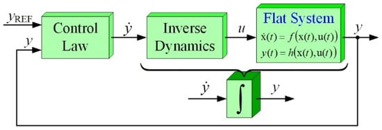
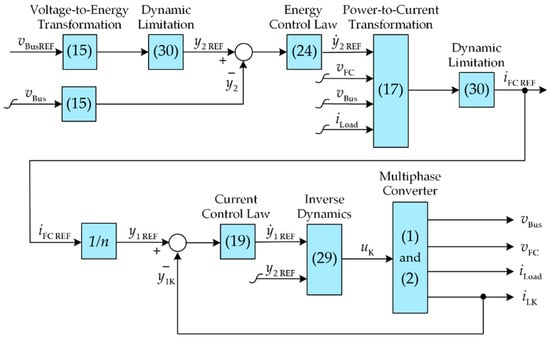
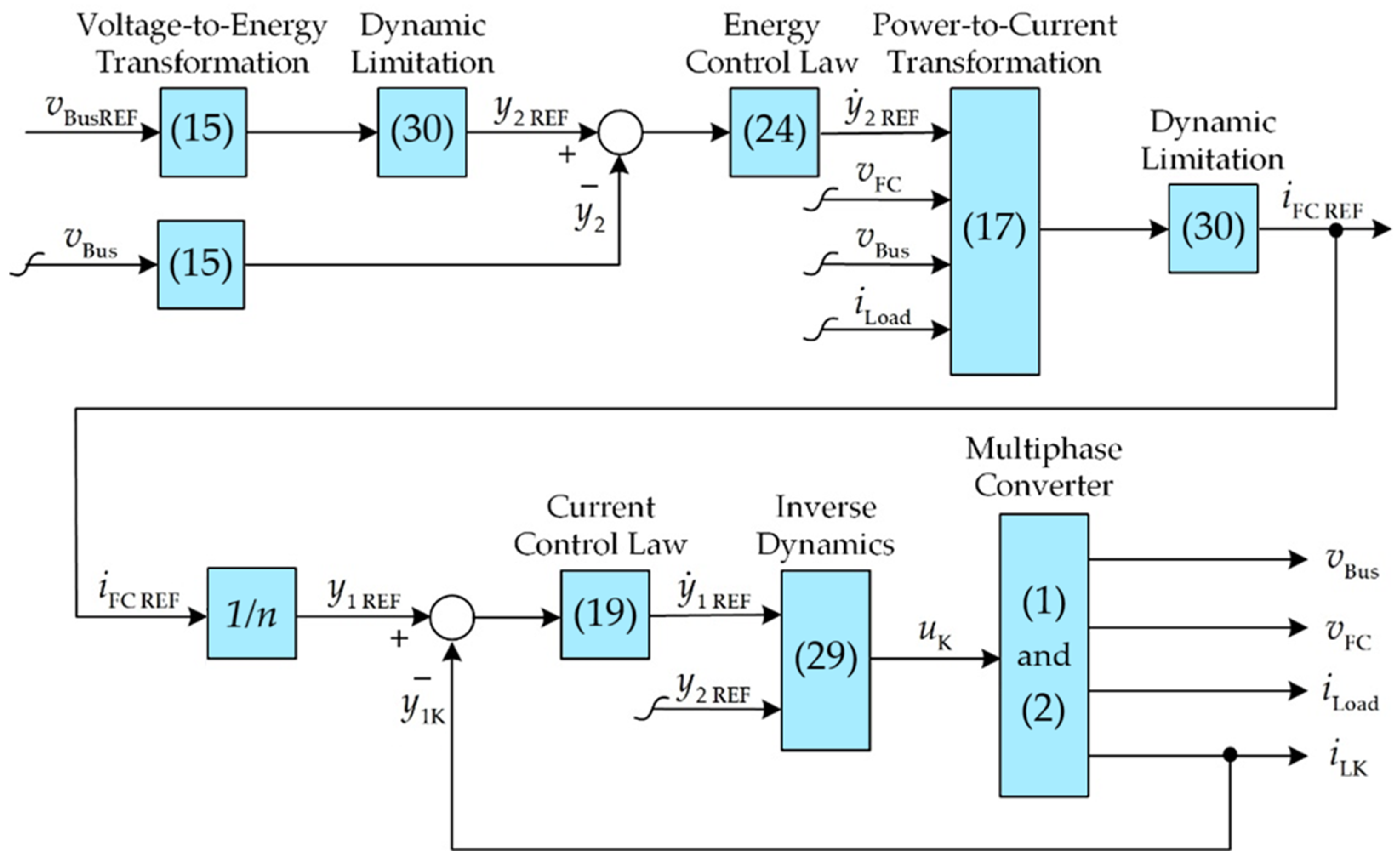
Although significant progress has been achieved in nonlinear control of DC–DC converters for fuel cell applications, most existing studies primarily emphasize either DC bus voltage regulation or current balancing independently. Furthermore, limited attention has been devoted to simultaneously regulating the DC bus energy and phase-current sharing of PEMFC-fed interleaved boost converters using a differential flatness framework while considering practical implementation issues associated with modeling uncertainties and converter nonidealities. Therefore, there remains a need for a computationally efficient nonlinear control strategy capable of achieving fast transient response, balanced current sharing, and reduced PEMFC current ripple under practical operating conditions. Table 1 summarizes the characteristics of representative nonlinear control strategies that have been reported for DC–DC converters in PEMFC applications. The comparison highlights the advantages and limitations of each method with respect to voltage regulation, current-sharing capability, computational complexity, and practical implementation, thereby motivating the development of the proposed control strategy. Based on the comparative analysis presented in Table 1, this paper proposes a differential flatness-based nonlinear control strategy for a PEMFC-fed multiphase interleaved boost converter intended for EV applications. The proposed control structure combines inner current regulation loops with an outer energy regulation loop to maintain stable DC bus voltage while ensuring balanced current sharing among converter phases. Particular attention is given to suppressing fuel cell current ripple during transient operation in order to reduce electrical stress on the PEMFC stack. Figure 1 illustrates the overall differential flatness-based control structure. The effectiveness of the proposed controller is experimentally verified using a 2.5 kW PEMFC platform and compared with a conventionally tuned PI controller under representative dynamic operating conditions.
Table 1.
Comparison of recent nonlinear controllers for PEMFC boost converters.
Figure 1.
The proposed control structure.
The main technical contributions of this study are summarized as follows:
- A differential flatness-based nonlinear control framework is developed for PEMFC-fed multiphase interleaved boost converters.
- The proposed controller simultaneously regulates the DC bus voltage and maintains balanced inductor current sharing among converter phases.
- The proposed approach reduces low-frequency ripple current during abrupt load transitions without relying on additional passive filtering components.
- The proposed differential flatness framework incorporates integral compensation into both the outer energy controller and inner current controller to improve robustness against modeling uncertainties and neglected converter parasitic effects encountered during practical implementation.
As summarized in Table 1, although numerous nonlinear control techniques have been reported for DC–DC converters, few studies have simultaneously addressed nonlinear DC bus voltage regulation, balanced phase-current sharing, and experimental validation on PEMFC-fed interleaved boost converters using differential flatness theory. Existing nonlinear control strategies generally provide satisfactory voltage regulation performance; however, they often involve trade-offs between computational complexity, robustness, and current-sharing capability. Sliding mode control and model predictive control exhibit excellent dynamic performance but require either more sophisticated controller design or higher computational resources. Although differential flatness-based control offers an analytical nonlinear solution with relatively low computational complexity, its practical performance strongly depends on model accuracy. To address these limitations, the proposed controller integrates differential flatness-based nonlinear feedforward control with integral feedback compensation, enabling simultaneous DC bus energy regulation, balanced phase-current sharing, and improved robustness against modeling uncertainties and neglected converter nonidealities. Furthermore, the proposed strategy is experimentally validated using a 2.5 kW PEMFC-fed interleaved boost converter under dynamic operating conditions, thereby demonstrating its practical applicability for electric vehicle power conversion systems.
The remainder of this paper is organized as follows. Section 2 presents the system configuration and mathematical modeling of the interleaved boost converter. Section 3 describes the proposed differential flatness-based control strategy. Section 4 presents the experimental setup and validation results. Finally, Section 5 concludes the paper.
2. System Configuration and Mathematical Modeling
2.1. Interleaved Boost Converter Topology
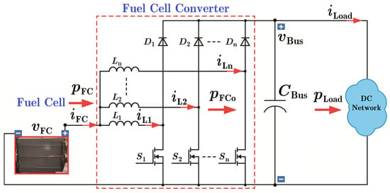
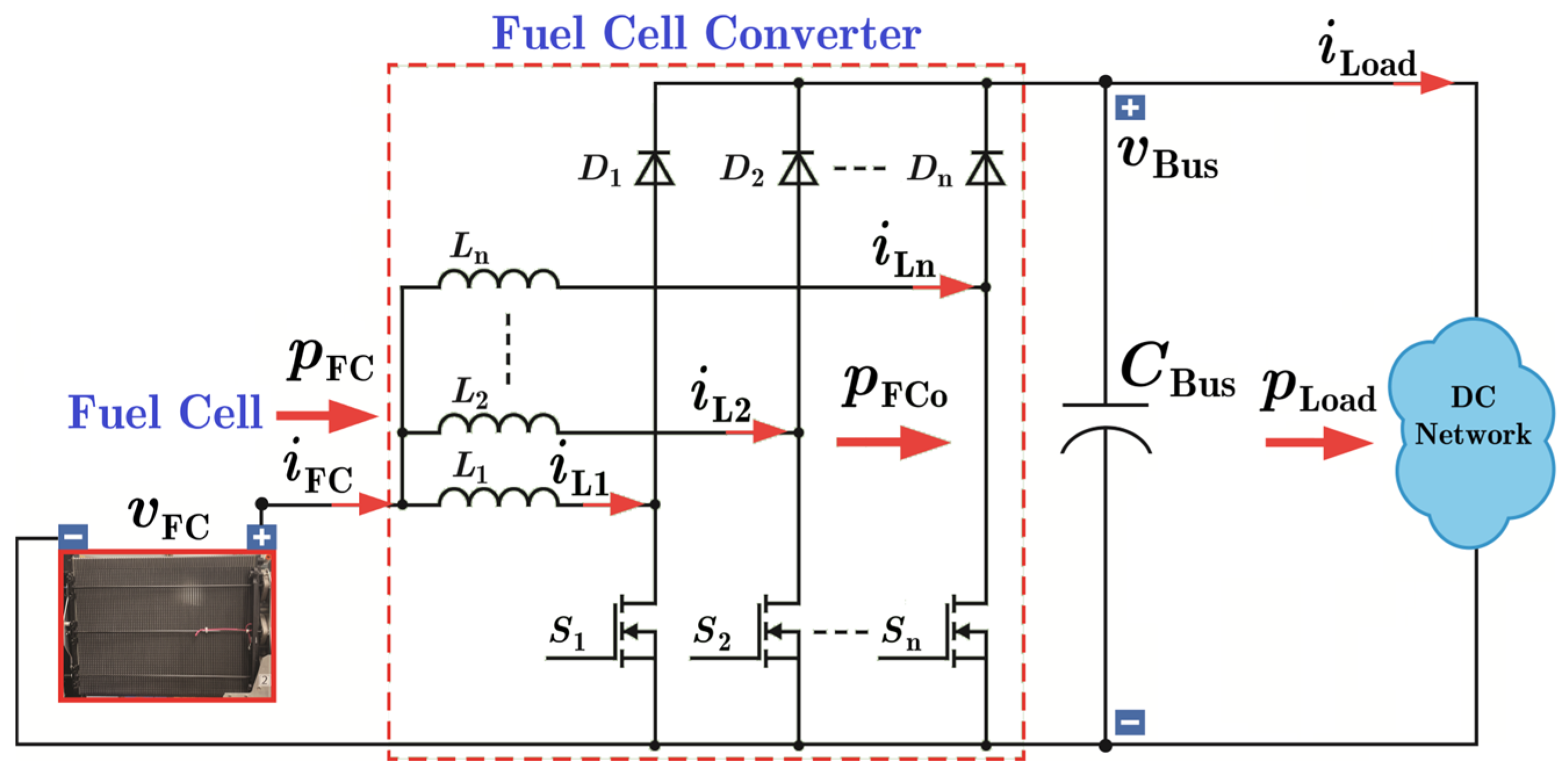
A multiphase interleaved boost converter, shown in Figure 2, is used to interface the PEMFC stack with the high-voltage DC bus of the EV traction system because the fuel cell stack produces a relatively low DC voltage [16,17]. In preliminary hardware testing, the interleaved configuration also reduced localized heating in the switching devices while lowering the input ripple current compared with the conventional single-phase topology.
Figure 2.
Configuration of the PEMFC-fed multiphase interleaved boost converter showing the principal electrical variables employed in the proposed differential flatness-based controller.
The proposed converter consists of two parallel boost phases operating with phase-shifted switching signals. In this study, a two-phase interleaved configuration was selected as a compromise between ripple reduction capability, hardware complexity, and laboratory-scale implementation. In the experimental setup, ripple cancelation between converter phases noticeably reduced current fluctuation at the PEMFC output terminals.
Figure 2 illustrates the overall configuration of the PEMFC-fed two-phase interleaved boost converter. The PEMFC stack serves as the primary energy source, while the interleaved boost converter raises the low fuel-cell voltage to the regulated DC bus voltage. The inductors and are employed to distribute the input current between converter phases, thereby reducing the input current ripple supplied by the PEMFC. Capacitor Cbus functions as the DC bus energy storage element to maintain the output voltage during transient operating conditions, whereas the load R represents the equivalent traction load of the electric vehicle.
The principal variables used throughout this paper are summarized as follows: denotes the PEMFC output voltage, represents the total fuel-cell current, and denote the inductor currents of Phases 1 and 2, respectively, is the DC bus voltage, and and are the duty-cycle commands of the corresponding boost converter switches. Based on the system configuration illustrated in Figure 2, the mathematical model of the two-phase interleaved boost converter is derived using the conventional state-space averaging technique under continuous-conduction-mode (CCM) operation. Since the converter switching frequency is significantly higher than the dominant electrical dynamics, the averaged model accurately represents the low-frequency behavior required for nonlinear controller synthesis while neglecting the switching ripple. To simplify the control-oriented analysis, parasitic resistances and semiconductor switching losses are neglected in the controller synthesis model. This simplified model is primarily adopted for differential flatness-based controller design and stability analysis, whereas the robustness of the proposed controller against practical nonidealities is experimentally verified in Section 4. The assumptions employed in the controller synthesis are commonly adopted in nonlinear converter control and provide an appropriate balance between analytical tractability and practical implementation.
2.2. Mathematical Modeling
To facilitate nonlinear controller synthesis, the mathematical model of the two-phase interleaved boost converter is derived using the conventional state-space averaging technique under continuous-conduction-mode (CCM) operation. Since the switching frequency is significantly higher than the dominant electrical dynamics of the converter, the averaged model accurately captures the low-frequency behavior required for nonlinear controller design while neglecting the high-frequency switching ripple. The controller synthesis model further assumes ideal switching devices, negligible parasitic resistances, and continuous inductor currents, which are commonly adopted assumptions in differential flatness-based control design. Under these assumptions, the interleaved boost converter can be represented by the following averaged state equations.
Equation (1) describes the averaged electrical dynamics of each converter phase. The first equation represents the voltage balance across the boost inductor, whereas the second equation corresponds to the energy balance of the DC bus capacitor according to Kirchhoff’s voltage and current laws.
where denotes the duty cycle of the converter phase, represents the inductor current of the converter phase, is the fuel cell voltage, and is the DC bus voltage.
The total fuel cell current, , is given by
As a result, the interleaving operation distributes the phase currents among converter branches while minimizing the resultant ripple current at the fuel cell input.
For the proposed energy-based control strategy, the instantaneous power supplied by the PEMFC can be expressed as
which is transferred through the interleaved boost converter to the DC bus capacitor and the load. Consequently, regulating the DC bus energy indirectly governs the instantaneous power balance between the PEMFC source and the load demand during transient operation.
2.3. Assumptions Used in Controller Design
The controller synthesis is based on the following assumptions:
- Continuous conduction mode operation is maintained.
- The switching frequency is significantly higher than the converter dynamic bandwidth.
- Converter parasitic resistances and semiconductor voltage drops are neglected during controller synthesis but are compensated by the integral action incorporated in the proposed control strategy.
- The PEMFC output voltage varies slowly compared with the converter electrical dynamics during one switching period.
3. Differential Flatness-Based Nonlinear Control
3.1. Differential Flatness Formulation
Differential flatness theory was originally introduced by Fliess et al. within the framework of differential algebra [22,23]. In this approach, a nonlinear dynamic system is represented using state and input variables defined over a differential field. A system is considered differentially flat when a suitable set of flat outputs can be identified such that all system states and control inputs can be algebraically reconstructed from these outputs and a finite number of their derivatives.
For converter control applications, this property is particularly attractive because reference trajectories can be generated directly without solving nonlinear state equations through numerical integration [24]. As a result, the controller design process becomes more suitable for real-time implementation while preserving the nonlinear dynamics of the converter system.
If the number of flat outputs is equal to the number of control inputs, the system states and input variables can be reconstructed directly from the flat outputs and their derivatives. Based on this property, the general nonlinear system can be expressed as follows:
where , , and represent the system state vector, control input vector, and flat output vector, respectively.
Differential flatness provides a systematic framework for transforming the nonlinear converter dynamics into an equivalent linear representation through an appropriate selection of flat outputs. Once the flat outputs are determined, all state variables and control inputs can be expressed algebraically in terms of the flat outputs and a finite number of their time derivatives. Consequently, the controller can be synthesized without requiring local linearization around a specific operating point, making the proposed approach particularly suitable for the large-signal operating conditions encountered in PEMFC-powered electric vehicles.
For the proposed two-phase interleaved boost converter, the selected flat outputs correspond to the DC bus energy and the individual inductor currents. These variables are physically measurable and directly related to the principal control objectives, namely DC bus voltage regulation and balanced current sharing between converter phases. Therefore, the resulting flat outputs enable straightforward derivation of the corresponding inverse dynamics while preserving the nonlinear characteristics of the converter.
Based on the selected flat outputs, the remaining state variables and duty-cycle control inputs can be uniquely reconstructed without numerical optimization or iterative computation. This property significantly reduces the computational burden compared with several optimization-based nonlinear control approaches, thereby facilitating practical implementation in embedded automotive control platforms.
Equations (10)–(12) define the nonlinear state-space representation used throughout the controller synthesis. The state vector, input vector, and output vector are explicitly introduced to establish a complete mathematical description of the converter dynamics prior to deriving the inverse flatness-based control law. Based on the above differential flatness formulation, the proposed nonlinear tracking controller is subsequently developed through inverse dynamic transformation. The controller combines feedforward compensation derived from the flatness property with feedback regulation to enhance robustness against modeling uncertainties and external disturbances.
3.2. Proposed Differential Flatness-Based PI Controller Design
The proposed control architecture adopts a cascaded structure consisting of an outer-loop energy regulator and inner-loop current regulators. The outer loop is responsible for maintaining the DC bus energy, which is directly related to the DC bus voltage, whereas the inner loops regulate the inductor currents of the individual converter phases to guarantee balanced current sharing. This hierarchical structure enables simultaneous voltage regulation and ripple current suppression while preserving the nonlinear characteristics of the converter. In the proposed controller design, the controlled variables are selected as the flat outputs of the converter system. For the inner control loops, the inductor currents of each converter phase are selected as the primary flat outputs in order to maintain balanced current sharing during dynamic operating conditions.
The first flat output and its derivative are defined by (13) and (14), respectively.
The stored energy of the DC bus capacitor is selected as the second flat output, which is directly related to the DC bus voltage stability. The corresponding stored energy and power expressions are given in (15) and (16).
Using the converter power balance relationship, the fuel cell output power can be expressed as the sum of the capacitor power and load power components, as described in (17). The load power is determined from the DC bus voltage and load current.
Based on the differential flatness formulation, the duty cycle of each converter phase can be obtained from the flat input variable, as expressed in (18).
3.3. Proposed Flatness-Based PI Control Laws
The control laws presented in this section are derived from the inverse dynamics of the ideal averaged converter model established in Section 2. Although the differential flatness framework provides an exact nonlinear inversion under ideal assumptions, practical implementations inevitably exhibit parameter uncertainties, parasitic resistances, semiconductor voltage drops, and modeling inaccuracies. To compensate for these unmodeled dynamics and eliminate steady-state tracking errors, an integral feedback term is incorporated into the proposed tracking control laws. Consequently, the proposed controller combines the nonlinear feedforward action obtained from differential flatness with integral feedback compensation, thereby improving robustness against practical nonidealities while preserving the fast transient response of the flatness-based formulation.
The inner current control loop is designed based on the reference trajectory of the inductor currents. A linear closed-loop tracking law is introduced to ensure asymptotic convergence of the inductor current tracking error.
Equation (19) defines the nonlinear tracking-error dynamics adopted for the outer-loop energy regulation. The feedforward component is directly obtained from the differential flatness formulation, whereas the proportional–integral feedback terms compensate for parameter uncertainties, converter losses, and slowly varying disturbances that are not explicitly represented in the ideal averaged model. Consequently, the closed-loop system preserves the fast transient characteristics of flatness-based control while achieving zero steady-state tracking error under practical operating conditions. The controller gains are determined by matching the characteristic polynomial to the desired closed-loop pole locations. This approach allows the transient response and damping characteristics of the current loop to be adjusted systematically.
For the outer control loop, the stored energy of the DC bus capacitor is selected as the regulated variable in order to maintain stable DC bus voltage during load transients.
The same design philosophy is adopted for the inner-loop current regulation. The integral action compensates for the steady-state current-sharing error caused by parameter mismatch between converter phases, including inductor tolerances, semiconductor voltage drops, and other unmodeled nonidealities. This feedback correction enhances the robustness of the proposed controller without altering the nonlinear feedforward structure derived from the differential flatness property. The controller parameters of the outer loop are similarly selected using the desired closed-loop pole locations to obtain the required transient response characteristics.
Although dedicated parameter perturbation experiments were beyond the scope of this work, the integral feedback incorporated into the proposed flatness-based PI controller improves robustness against moderate modeling uncertainties, component tolerances, and converter parameter variations. Consequently, satisfactory closed-loop performance is expected to be maintained under practical operating conditions, where gradual parameter deviations and nonideal converter characteristics are unavoidable.
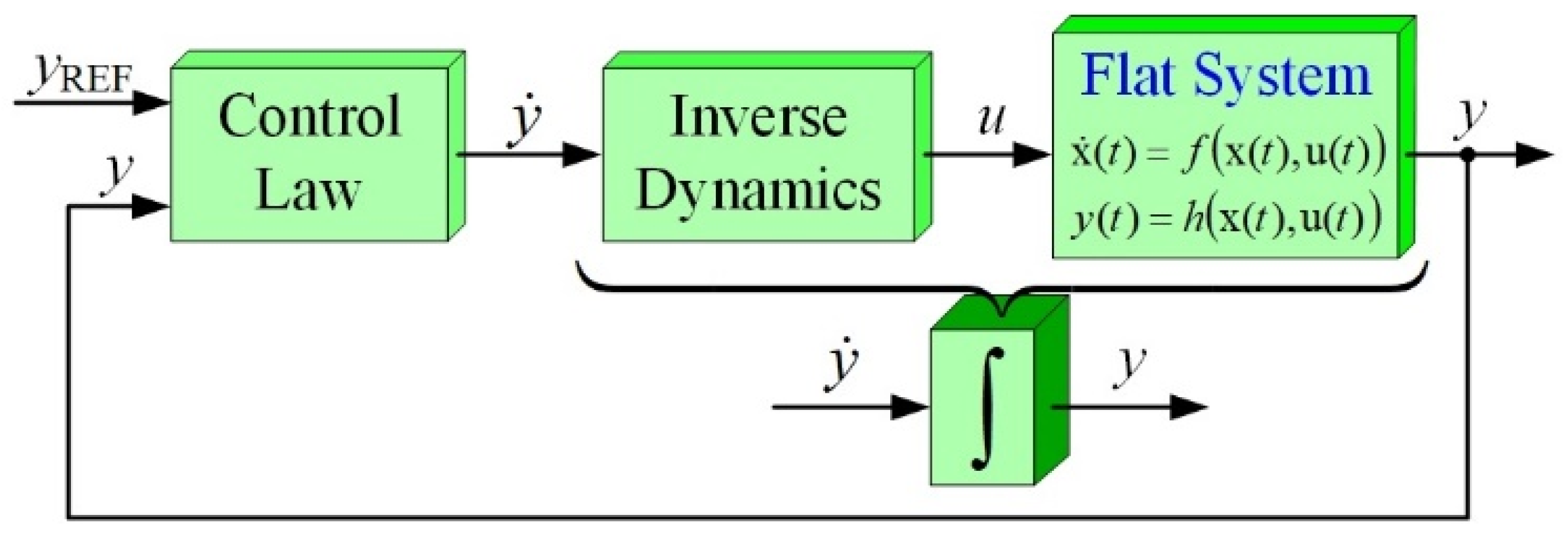
With properly selected controller gains, damping ratios, and natural frequencies, the overall closed-loop system remains asymptotically stable. Figure 3 illustrates the proposed differential flatness-based energy/current cascade control structure.
Figure 3.
Diagram of the differential flatness-based energy/current cascade control concept.
By substituting the desired tracking dynamics into the nonlinear averaged converter model presented in Section 2, the inverse dynamics of each converter phase can be explicitly derived. Accordingly, the duty-cycle command is analytically obtained from the converter state equations rather than empirical tuning, thereby preserving the nonlinear characteristics of the boost converter throughout the entire operating range.
Using the measured converter states, the flat input variables are calculated in real time to determine the duty cycle command for each converter phase, as described in (29).
Equation (29) constitutes the final inverse dynamic control law used to generate the duty-cycle command for each converter phase. The duty-cycle expression is obtained directly from the nonlinear averaged converter model through differential flatness-based inversion, thereby preserving the nonlinear characteristics of the boost converter over a wide operating range. Unlike conventional PI controllers, the proposed formulation explicitly incorporates the converter nonlinear dynamics into the feedforward term, while the proportional–integral feedback terms compensate for modeling uncertainties, parasitic effects, and external disturbances. Consequently, the proposed flatness-based PI controller achieves improved transient performance without sacrificing steady-state regulation accuracy.
Because the proposed flatness-based PI controller is implemented using explicit algebraic expressions together with conventional PI calculations, it does not require iterative optimization, matrix inversion, or discontinuous switching actions during real-time operation. Consequently, its computational complexity is significantly lower than that of optimization-based nonlinear control methods, facilitating practical implementation on standard DSP platforms with modest computational resources.
To facilitate practical implementation, the controller gains were selected according to the desired closed-loop bandwidth and damping characteristics. The initial gain values were estimated from the linearized error dynamics to obtain a well-damped transient response, and were subsequently fine-tuned experimentally to account for digital implementation delay, measurement noise, and converter parameter tolerances. The final gain values provided a satisfactory compromise between fast dynamic response, robustness, and current-sharing accuracy over the entire operating range of the 2.5 kW PEMFC prototype.
4. Experimental Validation
4.1. Experimental Setup
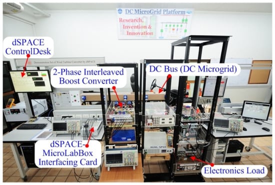
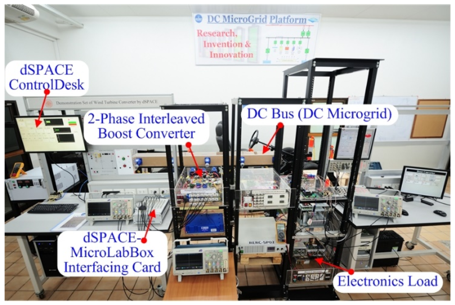
The proposed control strategy was experimentally validated using a two-phase interleaved boost converter prototype. A laboratory-scale DC microgrid test bench was developed to evaluate converter performance under practical operating conditions. The parameters of the converter system are summarized in Table 2.
Table 2.
Converter devices and parameters.
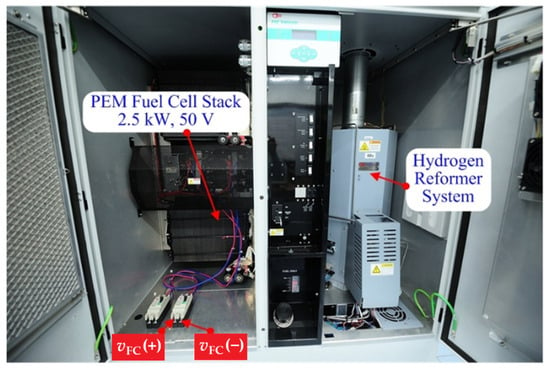
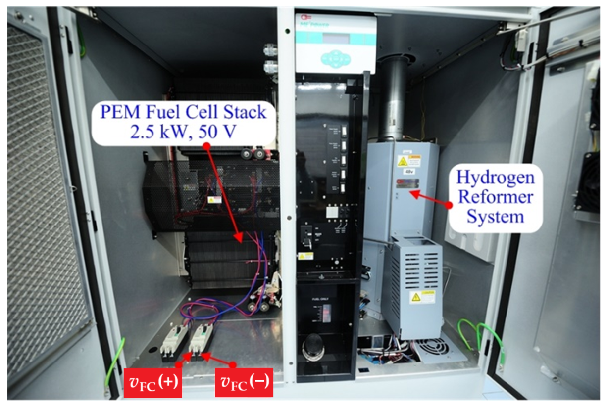
A 2.5 kW PEMFC stack rated at 50 V was used as the primary DC power source for evaluating both transient and steady-state converter behavior. A two-phase interleaved configuration was selected as a compromise between ripple reduction capability, hardware complexity, and laboratory-scale implementation. The proposed differential flatness-based control algorithm was implemented using a dSPACE DS1202 MicroLabBox real-time control platform, as shown in Figure 4. The control algorithm was executed synchronously with the converter switching frequency at 25 kHz. In the experimental setup, the switching frequency was fixed at 25 kHz. The controller parameters used for regulating the capacitor stored energy and inductor currents are summarized in Table 3.
Figure 4.
Laboratory-scale DC microgrid test bench used for experimental validation.
Table 3.
Controller parameters.
The converter was configured to regulate the DC bus voltage at 100 V during all experimental tests. The 100 V DC bus adopted in this study was selected as a laboratory-scale operating condition for experimental validation of the proposed controller. Although commercial electric vehicle traction systems commonly employ substantially higher DC bus voltages, the proposed flatness-based PI control strategy is formulated from the normalized nonlinear converter dynamics and is therefore independent of the absolute bus voltage level. Consequently, the proposed control methodology can be extended to higher-voltage PEMFC power conversion systems through appropriate converter and component redesign without modifying the fundamental control principle.
The proposed controller was experimentally implemented on the DSP platform shown in Figure 5. Owing to the analytical formulation provided by differential flatness, the control algorithm does not require iterative optimization or online numerical computation. Consequently, the proposed flatness-based PI controller can be readily implemented on embedded digital controllers for real-time power-conversion applications.
Figure 5.
Experimental PEMFC/reformer system rated at 2.5 kW and 50 V.
Although the PEMFC system has a rated power of 2.5 kW, the transient experiments presented in this study were intentionally limited to a maximum load demand of 1 kW to ensure safe operation of the laboratory prototype and to avoid excessive thermal stress on the fuel-cell stack during repeated transient testing. Since the proposed controller is derived from the nonlinear averaged model rather than a specific operating point, its control law remains applicable throughout the rated operating range.
Table 4 summarizes the principal transient-performance indices obtained from the experimental load-transition tests. Compared with the conventional PI controller, the proposed flatness-based PI controller reduced the DC bus voltage recovery time by approximately 67% and decreased the maximum transient voltage deviation by approximately 50%, while both controllers were evaluated under identical operating conditions and using the same ±2% settling criterion. These results demonstrate the superior transient regulation capability of the proposed nonlinear control strategy.
Table 4.
Performance comparison between the proposed and the conventional PI controllers.
4.2. Experimental Results
This section experimentally evaluates the proposed flatness-based PI controller under various operating conditions representative of practical PEMFC-powered electric vehicle applications. The controller performance is assessed in terms of DC bus voltage regulation, transient response, current-sharing accuracy, and PEMFC current ripple suppression. The same experimental platform was employed for both the proposed controller and the conventional PI controller to ensure a fair comparison.
4.2.1. Steady-State Operation
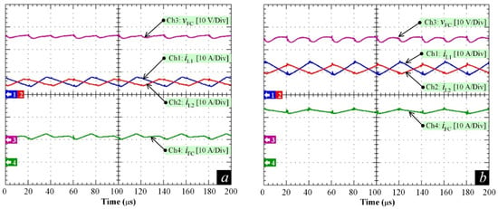
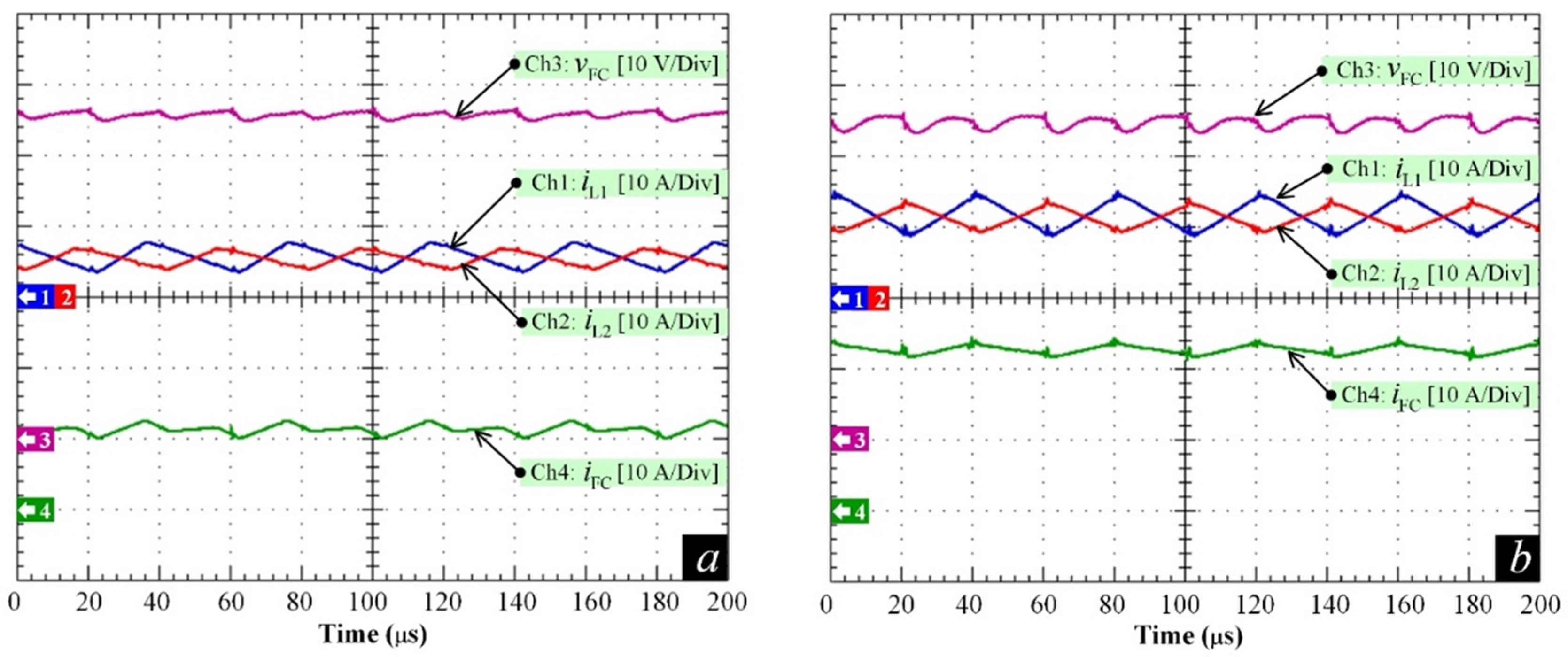
The steady-state performance of the proposed two-phase interleaved boost converter was evaluated at output power levels of 500 W and 1 kW, as shown in Figure 6. Overall, the experimental results confirmed stable DC bus regulation together with satisfactory current-sharing performance under both steady-state operating conditions.
Figure 6.
Steady-state characteristics of the proposed two-phase interleaved converter at load powers of (a) 500 W; and (b) 1000 W.
Figure 6 presents the steady-state experimental performance of the proposed flatness-based PI controller under nominal operating conditions. The experimental results demonstrate stable DC bus voltage regulation with balanced inductor currents, thereby confirming the effectiveness of the proposed nonlinear control strategy. The measured inductor current waveforms of both phases are consistent with the expected phase-shift operation of the interleaved converter, resulting in partial ripple cancelation at the converter input.
During the experiments, a slightly higher ripple magnitude was observed in the first-phase inductor current because of a small inductance mismatch between the two phases. Nevertheless, the average current of both phases remained nearly identical, indicating that the proposed control strategy maintained satisfactory current balancing under steady-state operation. Consequently, the average currents remained well balanced, preventing unequal thermal loading of the power semiconductor devices and improving converter reliability during continuous operation. The experimental waveforms also demonstrate that the interleaved converter structure effectively suppresses the net PEMFC input current ripple through phase-shift current cancelation. This reduction in ripple current is beneficial for mitigating electrochemical stress on the fuel-cell membrane and contributes to improved long-term operational reliability. Although electrochemical impedance measurements were beyond the scope of this work, previous studies have reported that reduced current ripple is closely associated with improved PEMFC durability.
4.2.2. Dynamic Performance Test
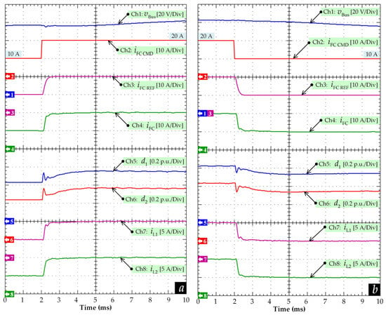
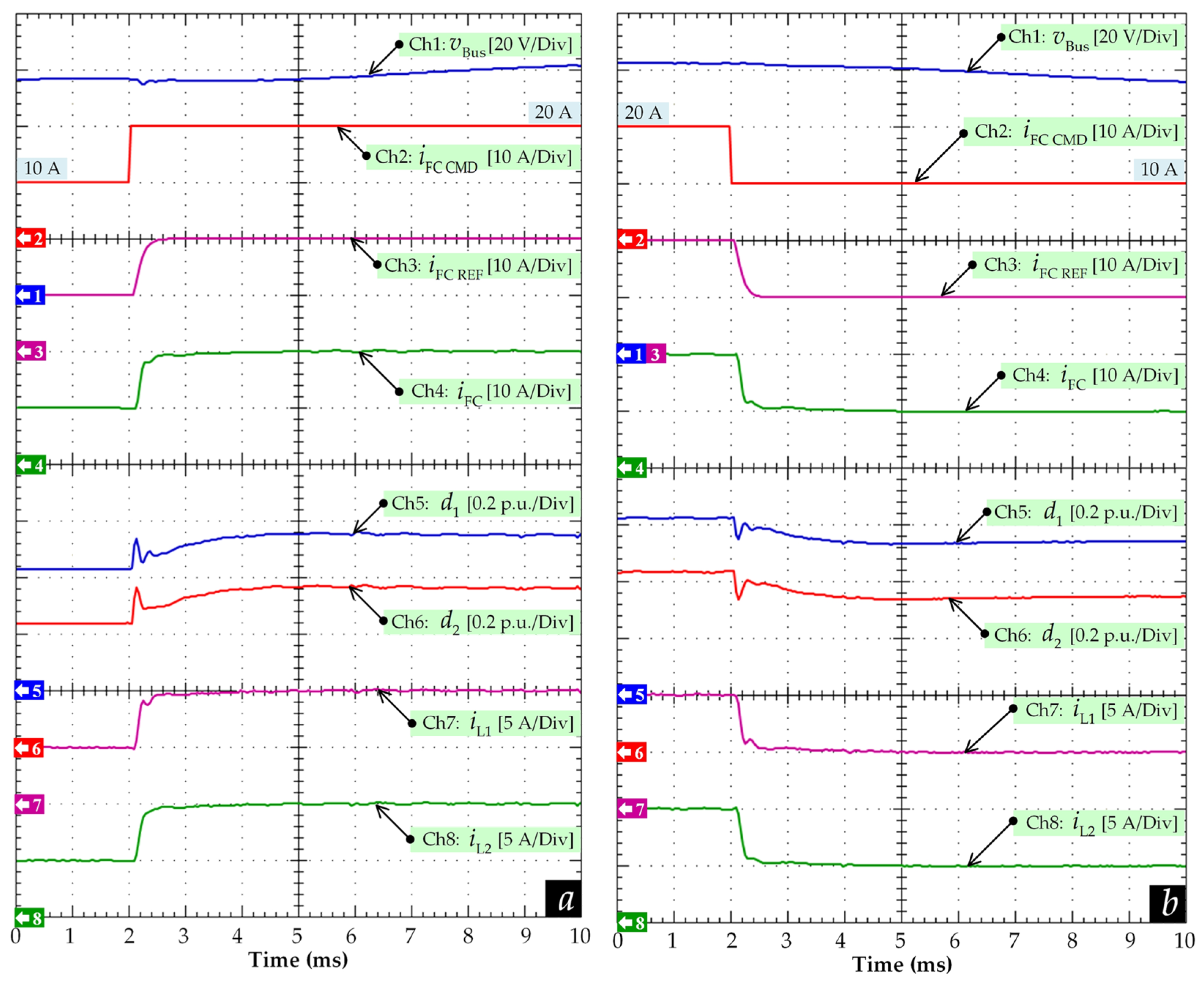
To evaluate the transient response of the proposed controller, dynamic tests were conducted by applying step changes to the fuel cell current reference. The reference current was increased from 10 A to 20 A and subsequently decreased from 20 A to 10 A, as illustrated in Figure 7. During the step-up transient, the DC bus voltage began recovering toward its steady-state operating condition within approximately 10 ms, whereas the measured settling time based on a ±2% criterion was approximately 50 ms. The measured inductor current imbalance between phases remained below 3% during the transient interval. The observed fast transient recovery can be attributed to the analytical nonlinear feedforward action derived from differential flatness together with the proportional–integral feedback compensation. The feedforward component explicitly accounts for the nonlinear converter dynamics through inverse-system formulation, whereas the proportional–integral feedback compensates for modeling uncertainties, neglected parasitic effects, and external disturbances. Consequently, the proposed flatness-based PI controller achieves rapid reference tracking while maintaining stable DC bus voltage regulation and balanced current sharing during large-signal transient operation.
Figure 7.
Dynamic responses during commanded fuel cell current transitions: (a) stepped up from 10 A to 20 A; and (b) stepped down from 20 A to 10 A.
Similarly, during the step-down transient, the DC bus voltage exhibited only a small transient deviation before returning to its steady-state value. The experimental results confirm that the proposed control strategy maintained stable DC bus voltage regulation despite the relatively slow dynamic characteristics of the PEMFC.
The waveforms presented in Figure 7 were directly acquired from the digital oscilloscope without additional digital filtering or off-line post-processing. Therefore, the recorded signals accurately represent the practical transient behavior of the experimental prototype, including the switching ripple and measurement noise associated with the converter operation.
To protect the PEMFC from excessive electrical and thermal stress, the fuel cell reference current generated by the controller was intentionally passed through a second-order low-pass filter before being applied to the current control loop. This filtering process limited abrupt current variations demanded from the fuel cell while preserving the fast dynamic response of the DC bus voltage regulation. The measured fuel cell current closely followed the filtered reference trajectory under both transient conditions, confirming the satisfactory tracking capability of the proposed controller.
Overall, the experimental results demonstrate that the proposed flatness-based PI controller achieves fast voltage recovery, accurate current tracking, and satisfactory current-sharing performance under rapid load variations, thereby providing a solid basis for the comparative evaluation with the conventional PI controller presented in the following subsection.
Although impedance measurement was beyond the scope of the present study, the proposed reduction in PEMFC input current ripple may also facilitate impedance-based health monitoring by reducing electrochemical stress and improving the stability of operating conditions. Consequently, integrating real-time impedance monitoring with the proposed flatness-based PI controller represents a promising direction for future research to simultaneously achieve advanced control and condition monitoring of PEMFC systems.
4.2.3. Control Robustness Test
A robustness evaluation was performed to verify the performance of the proposed flatness-based PI controller under abrupt load disturbances while employing the simplified converter model introduced in Section 2. As discussed previously, the controller was synthesized using an ideal averaged model in which parasitic resistances, semiconductor voltage drops, and converter losses were neglected. In practical converter systems, however, these nonidealities inevitably influence the converter dynamics. Therefore, this experimental evaluation was conducted to verify that the proportional–integral feedback compensation can effectively mitigate the influence of modeling uncertainties and neglected parasitic effects under realistic operating conditions.
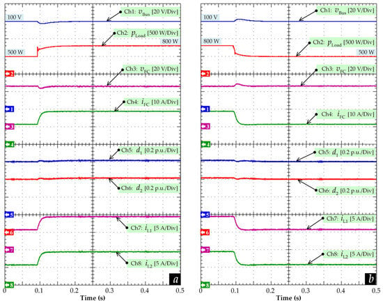
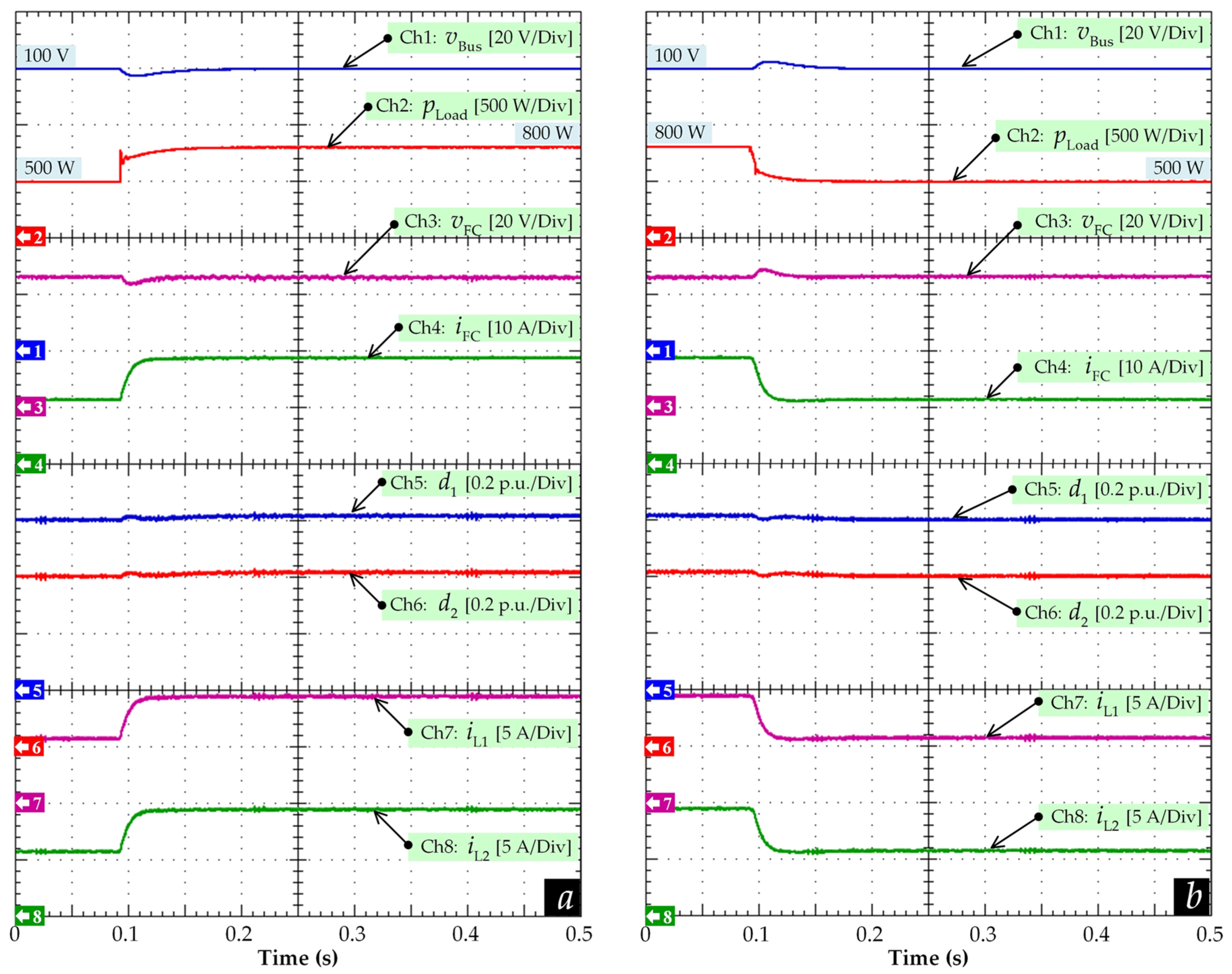
Figure 8 illustrates the experimental responses of the proposed controller during large load transitions from 500 W to 800 W and subsequently from 800 W back to 500 W. During the load increase, the sudden rise in output power demand temporarily reduced the DC bus voltage because the converter required additional energy from the PEMFC. Nevertheless, the proposed controller rapidly compensated for the voltage deviation and restored the DC bus voltage to its nominal operating condition within approximately 50 ms.
Figure 8.
DC bus voltage response during large load transitions: (a) from 500 W to 800 W; and (b) from 800 W to 500 W.
Similarly, during the load reduction test, only a small voltage overshoot was observed before the converter smoothly returned to steady-state operation. Throughout both transient conditions, the measured fuel-cell current and inductor currents remained stable without noticeable oscillation, indicating satisfactory current regulation and phase-current sharing under varying load conditions.
The converter duty cycles were automatically updated according to the inverse dynamic control law derived from differential flatness. Meanwhile, the proportional–integral feedback continuously compensated for converter parameter mismatch, parasitic effects, and external disturbances. Consequently, the proposed flatness-based PI controller maintained satisfactory voltage regulation despite the simplified control-oriented model adopted for controller synthesis.
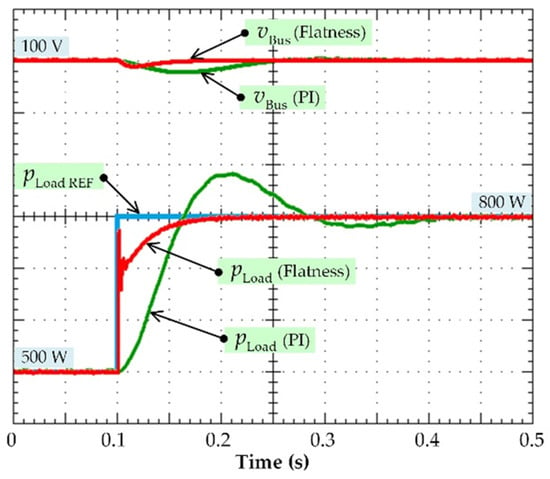
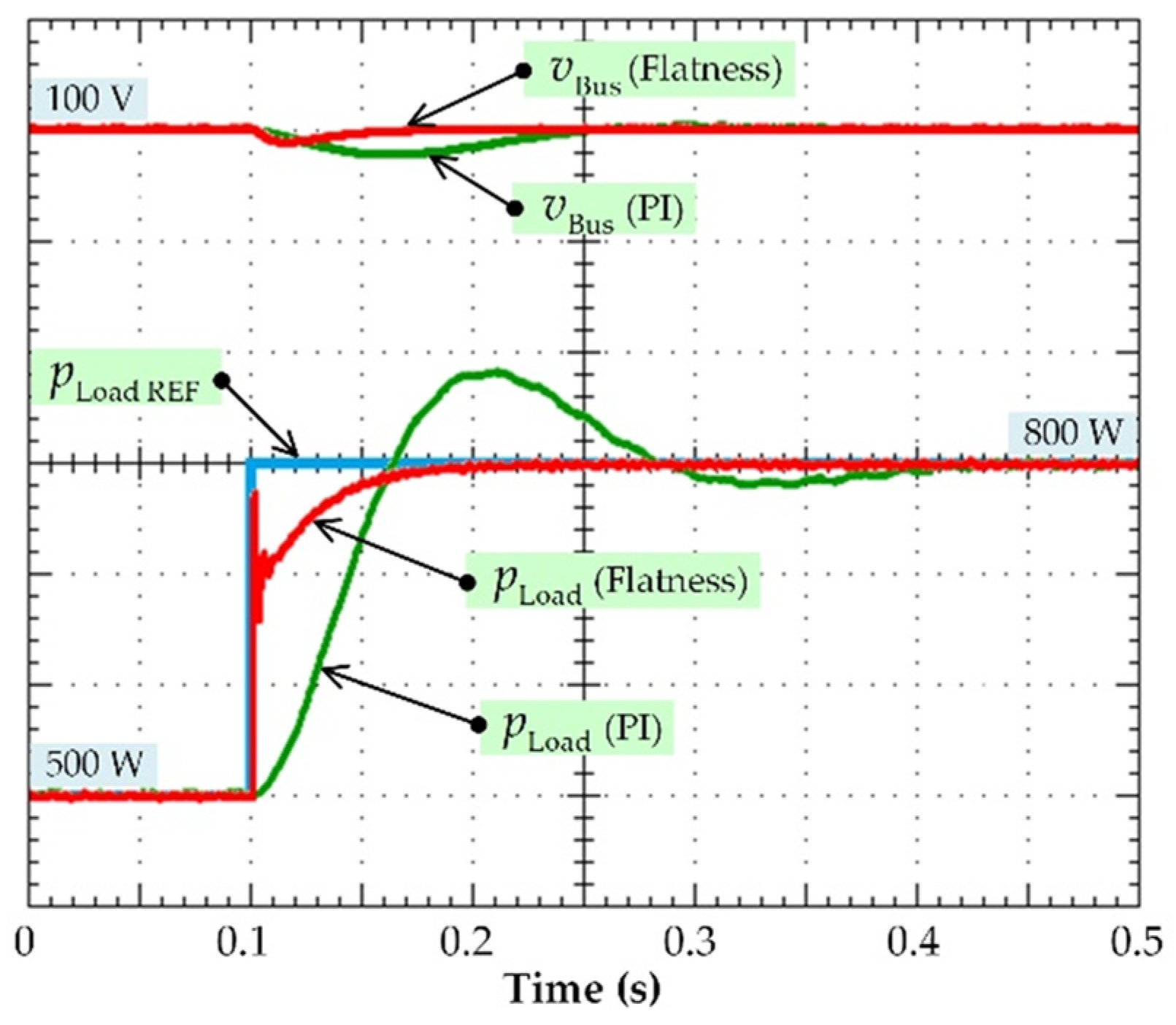
To further evaluate the transient performance, the proposed flatness-based PI controller was experimentally compared with a conventional cascade PI controller during large load-step transitions under identical operating conditions, as shown in Figure 9. The quantitative performance comparison between the two controllers is summarized in Table 4. For a fair comparison, both controllers were implemented on the same experimental platform using identical converter hardware, switching conditions, and load-transition profiles. The PI controller was tuned according to the conventional cascade-control design procedure, and the corresponding controller parameters are listed in Table 5.
Figure 9.
Comparison of transient load responses between the proposed controller and a conventional PI controller.
Table 5.
PI Controller design parameters used for experimental comparison.
The PI controller gains were initially selected based on the small-signal averaged model of the converter. The controller bandwidth was targeted to be approximately one decade lower than the switching frequency to ensure adequate separation between the control and switching dynamics, while a phase margin of approximately 60° was adopted to provide stable operation with sufficient robustness. The resulting gains were subsequently fine-tuned experimentally under the nominal operating condition to compensate for implementation delays and practical converter nonidealities.
Table 5 summarizes the controller configuration and tuning conditions adopted for the conventional PI controller. Both the proposed controller and the conventional PI controller were implemented on the same hardware platform and evaluated under identical operating conditions to ensure a fair and unbiased experimental comparison. The PI controller was tuned according to the conventional cascade-control design procedure, and the same switching frequency and load-transition profile were adopted for both controllers.
As summarized in Table 4, the proposed controller reduced the DC bus voltage recovery time by approximately 67%, from 150 ms to 50 ms, based on the measured settling time using a ±2% settling criterion. Furthermore, the maximum transient DC bus voltage deviation was reduced from approximately 1.0 V to 0.5 V relative to the nominal 100 V DC bus voltage, corresponding to a 50% reduction in voltage deviation. These improvements can be attributed to the nonlinear feedforward action derived from differential flatness, together with the proportional–integral feedback compensation, which effectively mitigates modeling uncertainties, neglected parasitic effects, and external disturbances. Consequently, the proposed flatness-based PI controller provides superior disturbance rejection and faster transient regulation while maintaining stable converter operation.
5. Conclusions
This study investigated a flatness-based PI nonlinear control strategy for a PEMFC-fed two-phase interleaved boost converter intended for electric vehicle applications. The proposed control structure combines differential flatness-based nonlinear feedforward control with proportional–integral feedback compensation to achieve stable DC bus voltage regulation, balanced phase-current sharing, and reduced fuel-cell current ripple under dynamic operating conditions. Experimental validation confirmed satisfactory steady-state operation, fast transient response, and robust performance despite the use of a simplified control-oriented converter model.
Compared with a conventional cascade PI controller operating under identical experimental conditions, the proposed controller reduced the DC bus voltage recovery time from 150 ms to 50 ms, corresponding to an improvement of approximately 67%, while the maximum transient voltage deviation decreased from approximately 1.0 V to 0.5 V. In addition, the measured current imbalance between the two converter phases remained below 3% during transient operation, demonstrating satisfactory current-sharing capability. These experimental results confirm that the proposed flatness-based PI controller provides superior transient regulation and disturbance rejection while maintaining low computational complexity suitable for real-time embedded implementation.
The proposed control strategy also contributes to reducing the low-frequency current ripple applied to the PEMFC through the combined effects of interleaved operation and nonlinear energy-based control. Although electrochemical impedance measurements were beyond the scope of this work, the observed reduction in fuel-cell current ripple is expected to alleviate electrical stress and contribute to improved long-term durability of the PEMFC stack.
The present investigation was experimentally validated using a 2.5 kW PEMFC platform with dynamic load transitions up to 1 kW, primarily to verify the practical feasibility of the proposed controller under representative operating conditions. Future work will include experimental evaluation over the full rated operating range of the converter, comprehensive robustness analysis under wider parameter uncertainties, and comparative investigations with other advanced nonlinear control strategies, including sliding-mode control and model predictive control. Overall, the proposed flatness-based PI controller demonstrates strong potential for high-performance PEMFC power-conditioning systems requiring fast transient response, stable DC bus regulation, and reliable current-sharing performance in electric vehicle applications.
Author Contributions
Conceptualization, S.P. and P.T.; methodology, S.P. and P.T.; validation, W.T. and P.M.; formal analysis, B.N.-M., N.B. and P.T.; writing—original draft preparation, W.T. and P.M.; writing—review and editing, W.T., P.M. and P.T.; visualization, W.T. and P.M.; supervision, S.P., B.N.-M., N.B. and P.T. All authors have read and agreed to the published version of the manuscript.
Funding
This research was funded by the College of Industrial Technology, King Mongkut’s University of Technology North Bangkok (Grant No. Res-CIT0296/2022).
Data Availability Statement
The data presented in this study are available on reasonable request from the corresponding authors.
Acknowledgments
This work was supported by the framework agreement between the National University of Science and Technology POLITEHNICA Bucharest, Pitești University Centre (Romania), and King Mongkut’s University of Technology North Bangkok (Thailand), in part by an International Research Partnership “Electrical Engineering—Thai French Research Center (EE-TFRC)” under the French PIA project of the Lorraine Université d’Excellence (LUE), reference ANR-15-IDEX-04-LUE, in cooperation between Université de Lorraine (France) and King Mongkut’s University of Technology North Bangkok, in part by the National Research Council of Thailand (NRCT) under Research Team Promotion Grant (Senior Mathīvichai) under Grant No. N42A680561, and in part by the NSRF via the Program Management Unit for Human Resources & Institutional Development, Research and Innovation under Research project Grant No. B41G680025. Additional infrastructure was accessed by the projects 345/2021, SMIS 125119, and 308/2020, SMIS 127318, funded from the European Regional Development Fund within the Competitiveness Operational Program.
Conflicts of Interest
The authors declare no conflicts of interest.
References
- Zaino, R.; Ahmed, V.; Alhammadi, A.M.; Alghoush, M. Electric Vehicle Adoption: A Comprehensive Systematic Review of Technological, Environmental, Organizational and Policy Impacts. World Electr. Veh. J. 2024, 15, 375. [Google Scholar] [CrossRef] [Scilit]
- Gonzalez-Rodriguez, P.S.; Lozoya-Santos, J.D.J.; Gonzalez-Hernandez, H.G.; Felix-Herran, L.C.; Tudon-Martinez, J.C. Challenges and Opportunities for Extending Battery Pack Life Using New Algorithms and Techniques for Battery Electric Vehicles. World Electr. Veh. J. 2025, 16, 442. [Google Scholar] [CrossRef] [Scilit]
- Ahmed, U.; Fida, B.A.; Thumiki, V.R.R.; Marhoobi, S.S.H.A. Electric Vehicles Adoption Challenges in Oman: A Comprehensive Assessment and Future Prospects for Sustainable Cities. Front. Sustain. Cities 2024, 6, 1360203. [Google Scholar] [CrossRef] [Scilit]
- Sohrabi, F.; Rohaninejad, M.; Bemš, J.; Hanzálek, Z. Electrification of Transportation: A Hybrid Benders/SDDP Algorithm for Optimal Charging Station Trading. Int. J. Hydrogen Energy 2024, 89, 1060–1074. [Google Scholar] [CrossRef] [Scilit]
- Sujan, V.; Fan, J.; Jatana, G.; Sun, R. Nationally Scalable Hydrogen Fueling Infrastructure Deployment: A Megaregion Analysis and Optimization Approach. arXiv 2024, arXiv:2410.06033. [Google Scholar] [CrossRef] [Scilit]
- Selmi, T.; Khadhraoui, A.; Cherif, A. Fuel Cell-Based Electric Vehicles Technologies and Challenges. Environ. Sci. Pollut. Res. 2022, 29, 78121–78131. [Google Scholar] [CrossRef] [Scilit] [PubMed]
- Mancino, A.N.; Menale, C.; Vellucci, F.; Pasquali, M.; Bubbico, R. PEM Fuel Cell Applications in Road Transport. Energies 2023, 16, 6129. [Google Scholar] [CrossRef] [Scilit]
- Fang, T.; Vairin, C.; von Jouanne, A.; Agamloh, E.; Yokochi, A. Review of Fuel-Cell Electric Vehicles. Energies 2024, 17, 2160. [Google Scholar] [CrossRef] [Scilit]
- Sorlei, I.-S.; Bizon, N.; Thounthong, P.; Varlam, M.; Carcadea, E.; Culcer, M.; Iliescu, M.; Raceanu, M. Fuel Cell Electric Vehicles—A Brief Review of Current Topologies and Energy Management Strategies. Energies 2021, 14, 252. [Google Scholar] [CrossRef] [Scilit]
- Sriram, B.; Shirazi, S.; Kalyvas, C.; Ghassemi, M.; Chizari, M. Dynamic Load Optimization of PEMFC Stacks for FCEVs: A Data-Driven Modelling and Digital Twin Approach Using NSGA-II. Vehicles 2025, 7, 96. [Google Scholar] [CrossRef] [Scilit]
- El-Hameed, M.A.; Saeed, M.; Kabbani, A.; El-Hay, E.A. Enhancing Performance of PEM Fuel Cell Powering SRM System Using Metaheuristic Optimization. Energies 2025, 18, 2004. [Google Scholar] [CrossRef] [Scilit]
- Chaturvedi, S.; Wang, M.; Fan, Y.; Fulwani, D.; Hollweg, G.V.; Khan, S.A.; Su, W. Control Methodologies to Mitigate and Regulate Second-Order Ripples in DC-AC Conversions and Microgrids: A Brief Review. Energies 2023, 16, 817. [Google Scholar] [CrossRef] [Scilit]
- Valdez-Resendiz, J.E.; Rosas-Caro, J.C.; Sanchez, V.M.; Lopez-Nuñez, A.R. Experimental study of a fuel cell stack performance operating with a power electronics converter with high-frequency current ripple. Int. J. Hydrogen Energy 2025, 108, 66–75. [Google Scholar] [CrossRef] [Scilit]
- Yuan, T.; Li, H.; Wang, J.; Jia, D. Research on the Influence of Ripple Voltage on the Performance of a Proton Exchange Membrane Electrolyzer. Energies 2023, 16, 6912. [Google Scholar] [CrossRef] [Scilit]
- Hernández-Gómez, Á.; Langarica-Cordoba, D.; Martinez-Rodriguez, P.R.; Guilbert, D.; Ramirez, V.; Saldivar, B. PEM Fuel Cell Emulators: A Review. Electronics 2023, 12, 2812. [Google Scholar] [CrossRef] [Scilit]
- Al-Shammaa, A.A.; Farh, H.M.H.; Omotoso, H.O.; Ibrahim, A.-W.; Abdurraqeeb, A.M.; Alshaabani, A. RST-Controlled Interleaved Boost Converters for Enhanced Stability in CPL-Dominated DC Microgrids. Symmetry 2025, 17, 1585. [Google Scholar] [CrossRef] [Scilit]
- Trape, M.A.; Hellany, A.; Rizk, J.; Nagrial, M. Synchronous Buck Converter. Energies 2025, 18, 480. [Google Scholar] [CrossRef] [Scilit]
- Elele, M.J.M.; Pau, D.; Zhuang, S.; Facchinetti, T. Compensating PI Controller’s Transients with Tiny Neural Network for Vector Control of Permanent Magnet Synchronous Motors. World Electr. Veh. J. 2025, 16, 236. [Google Scholar] [CrossRef] [Scilit]
- Benbouhenni, H.; Boudjema, Z.; Bizon, N.; Thounthong, P.; Takorabet, N. Direct Power Control Based on Modified Sliding Mode Controller for a Variable-Speed Multi-Rotor Wind Turbine System Using PWM Strategy. Energies 2022, 15, 3689. [Google Scholar] [CrossRef] [Scilit]
- Tegani, I.; Kraa, O.; Ramadan, H.S.; Ayad, M.Y. Practical Energy Management Control of Fuel Cell Hybrid Electric Vehicles Using Artificial-Intelligence-Based Flatness Theory. Energies 2023, 16, 5023. [Google Scholar] [CrossRef] [Scilit]
- Gouhail, M.; Salhi, I.; El Mazoudi, E.H.; Doubabi, S. Adaptive Feedback Control for Four-Phase Interleaved Boost Converter Used with PEM Fuel Cell. Appl. Sci. 2024, 14, 9895. [Google Scholar] [CrossRef] [Scilit]
- Fliess, M.; Lévine, J.; Martin, P.; Rouchon, P. Flatness and Defect of Nonlinear Systems: Introductory Theory and Examples. Int. J. Control 1995, 61, 1327–1361. [Google Scholar] [CrossRef] [Scilit]
- Fliess, M.; Lévine, J.; Martin, P.; Rouchon, P. A Lie-Bäcklund Approach to Equivalence and Flatness of Nonlinear Systems. IEEE Trans. Autom. Control 1999, 44, 922–937. [Google Scholar] [CrossRef] [Scilit]
- Wang, X.; Sun, W. Trajectory Tracking of Autonomous Vehicle: A Differential Flatness Approach with Disturbance-Observer-Based Control. IEEE Trans. Intell. Veh. 2023, 8, 1368–1379. [Google Scholar] [CrossRef] [Scilit]

Disclaimer/Publisher’s Note: The statements, opinions and data contained in all publications are solely those of the individual author(s) and contributor(s) and not of MDPI and/or the editor(s). MDPI and/or the editor(s) disclaim responsibility for any injury to people or property resulting from any ideas, methods, instructions or products referred to in the content. |
© 2026 by the authors. Published by MDPI on behalf of the World Electric Vehicle Association. Licensee MDPI, Basel, Switzerland. This article is an open access article distributed under the terms and conditions of the Creative Commons Attribution (CC BY) license.