


Abstract
Addressing the critical challenges of low accuracy, response hysteresis, and insufficient adaptability to complex dynamic tracking conditions in the pressure buildup control strategy of the Electro-Hydraulic Brake system (EHB), this paper proposes a cascaded multi-loop control algorithm based on Active Disturbance Rejection Control (ADRC) and Sliding Mode Control (SMC). Specifically, an ADRC–based integrated position–speed controller is designed to simultaneously analyze the influence of motor speed and piston displacement, thereby mitigating the issue of performance degradation and simplifying the observation of internal system states. Furthermore, the pressure loop utilizes a feedforward-based SMC algorithm tailored to the strong nonlinearity and significant interference characteristics of the hydraulic–mechanical coupling. A joint simulation platform based on Matlab/Simulink and AMESim was established, followed by validation through vehicle tests on a One-box experimental vehicle under step, sinusoidal, and ramp pressure signals. Simulation results indicate that the steady-state pressure error is maintained below 0.1 MPa. Crucially, real vehicle tests demonstrate steady-state errors within ±0.2 MPa (ramp) and ±0.5 MPa (sinusoidal), with maximum dynamic tracking errors kept below 0.8 MPa and 1.2 MPa, respectively. These findings comprehensively verify the advantages of the proposed strategy in terms of response speed, steady-state accuracy, reliability, and robustness.
1. Introduction
With the rapid advancement of automotive electrification and intelligence, the by-wire chassis, as the core platform supporting advanced driving assistance and autonomous driving functions, has set extremely high standards for the response rate and control accuracy of the braking system. Due to deficiencies such as insufficient control accuracy and lagging response, traditional braking systems have gradually failed to meet the performance requirements of intelligent connected vehicles. the Electro-Hydraulic Braking system (EHB) has become a key technology for enhancing vehicle braking safety due to the independent controllability of each actuator unit. Among them, the precise regulation ability of the master cylinder pressure directly determines the overall performance level of the system.
Internationally, Continental Germany and Bosch have achieved remarkable results in the field of EHB [1]. The MKC1 launched by Continental in 2010 adopts a One-box solution, with a seven-pole pair permanent magnet synchronous motor directly driving the ball screw. It can build up to 15 MPa within 150 ms, and its braking efficiency is three times that of traditional systems. It also features foot-feel simulation and energy recovery functions [2]. It has been installed on the Alfa Romeo Giulia for mass production. Although the Bosch IPB system has a slightly lower transmission efficiency, it deeply integrates electric power assistance with ESC and remains a preferred choice for high-end vehicles. Domestic Wuhu Bethel and Shanghai Nassen have also made breakthroughs in their respective fields. The One-box architecture WCBS launched by Bethel in 2019 achieves the ASIL-D safety level, with a pressure control gradient of 0.1 MPa/ms. Under the emergency braking condition of 100 km/h, the braking distance is shortened by 2.3 m, and the energy recovery efficiency can reach 92.6% [3,4]. The NBooster launched by Nassen in 2018 has a response time of less than 200 ms, a pressure accuracy of up to 0.1 MPa, and a mechanical energy recovery efficiency of 99.99%. It also integrates modules such as ABS and ESC. Currently, it is installed on models like BYD E2.
As a new type of electromechanical hydraulic system, EHB is confronted with the challenge of precise and rapid regulation of the main cylinder pressure, and many scholars have conducted research on this. Todeschini [5] proposed a hybrid position–pressure switching controller, but due to the use of position mode and the absence of direct pressure feedback, static errors exist. Wei Lingtao et al. [6], in order to ensure the control performance of the pressure-building unit at high temperatures, established heat transfer and hydraulic models, estimated the coil temperature through methods such as recursive least squares, and designed a hierarchical control strategy based on Sliding Mode Control. Chen Zhicheng et al. [7] proposed a pressure-position-current multi-loop strategy for the nonlinear problem in active braking and designed an active anti-disturbance pressure loop controller with hydraulic disturbance compensation. Zhao et al. [8] proposed an adaptive cascade optimal braking control method, modeled the position–pressure relationship and considered the system nonlinearity. The experimental verification effect was good. In addition, mature technologies such as Sliding Mode Control [9], model predictive control (MPC) [10], and three-step nonlinear methods [11] have also been applied to solve related servo mechanism control problems.
While multi-loop and hierarchical control architectures have been extensively investigated in existing EHB literature, integrating these complex nonlinear strategies into real-time vehicle controllers while effectively mitigating hydraulic chattering remains a significant practical challenge. Therefore, the core contribution of this paper lies in bridging the gap between advanced multi-loop algorithms and actual in-vehicle EHB implementation. The specific contributions and novelties of this study are summarized as follows:
- (1)
- Practical Composite Controller Design: To address the severe nonlinearity and chattering issues typical in pressure control, a feedforward Sliding Mode Control (SMC) algorithm is integrated with an Active Disturbance Rejection Control (ADRC) framework. By utilizing the Extended State Observer (ESO) to actively estimate and compensate for internal system interference, the reliance on high switching gains is reduced, achieving a smoother physical control output without sacrificing tracking precision.
- (2)
- Hardware-Oriented Decoupled Architecture: A cascaded multi-loop control algorithm—comprising a pressure loop, a speed–position overall loop, and a current loop—is constructed strictly based on time-scale separation. This decoupled architecture avoids destructive inter-loop coupling, significantly improving control efficiency and making the algorithm highly suitable for real-time deployment on automotive microprocessors.
- (3)
- Rigorous Real-Vehicle Experimental Validation: Unlike many existing studies that remain confined to theoretical simulations or hardware-in-the-loop test benches, this study validates the proposed composite strategy on a real vehicle equipped with an EHB system. The steady-state and dynamic tracking performances were explicitly evaluated under demanding high-pressure boundary conditions (up to 10 MPa), providing highly valuable and reliable reference data for actual engineering deployment.
In addition, the broader theoretical background and related developments of electro-hydraulic braking systems can be found in [12,13,14,15,16,17,18,19,20,21,22,23,24,25,26,27,28].
2. Configuration Selection and Working Principle of the Electro-Hydraulic Braking System
2.1. Configuration Selection of the Electro-Hydraulic Braking System
The Electro-Hydraulic Braking system is mainly divided into two types of wire-controlled braking schemes: Two-box and One-box. The Two-box system consists of two independent modules, Ebooster (Robert Bosch GmbH, Stuttgart, Germany) and ESC, each containing its own dedicated ECU, sensors and actuators. It meets the braking redundancy requirements through valve switching and supports anti-lock braking, stability control and energy recovery. However, it has problems such as poor pedal feel, a complex system and high cost. The One-box system integrates functions such as brake assist, pressure control and stability control. Its core components include pedals, hydraulic drive, mode switching, hydraulic control and electronic control. It uses an electric cylinder instead of a plunger pump, which enables a faster pressure-building rate, higher control accuracy, and the integrated design significantly reduces volume and weight. Although the One-box system is more difficult to design and control, it has become a key research object of electronic hydraulic braking due to its performance advantages and characteristics suitable for intelligent driving and new energy vehicles. Therefore, this paper selects the One-box system as the configuration of the Electro-Hydraulic Braking system.
2.2. Working Principle of the Electro-Hydraulic Braking System
Under normal braking conditions, once the driver steps on the brake pedal to trigger the braking action, the system control unit will immediately capture the relevant command signal. The main cylinder isolation valve closes accordingly, while the motor isolation valve opens simultaneously. At this point, the motor starts and drives the booster cylinder to build pressure. During this process, the inlet solenoid valve of the wheel cylinder remains open all the time, while the outlet solenoid valve keeps closed, allowing the brake fluid to flow smoothly into the interior of the wheel cylinder and promoting a steady increase in the pressure of the wheel cylinder. When the wheel cylinder pressure rises to the target pressure value, the inlet solenoid valve will automatically close, while the outlet solenoid valve remains in its original closed state. The entire braking system then switches to the pressure-holding mode. After the driver completes the braking operation and releases the pedal, the liquid outlet solenoid valve of the wheel cylinder opens, and the system enters the pressure-relief process. After the pressure relief is completed, all relevant valves and actuators are reset to their initial state, preparing for the next braking operation. If the electric hydraulic pump in the system malfunctions, the master cylinder isolation valve will automatically switch to the open state, creating a direct passage between the mechanical brake master cylinder and the wheel cylinder. This design ensures that drivers can directly use the brake pedal and rely on traditional braking efficiency to brake, guaranteeing driving safety.
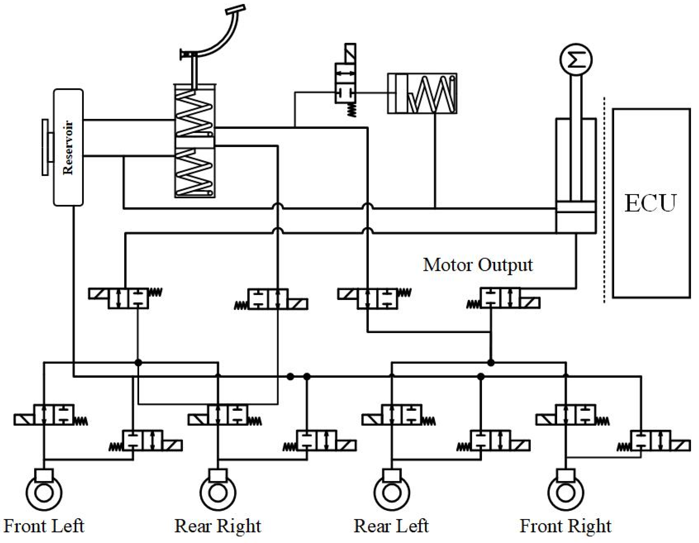
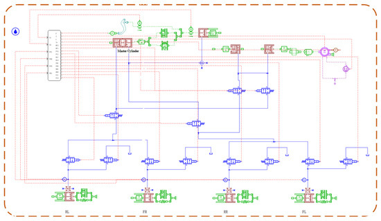
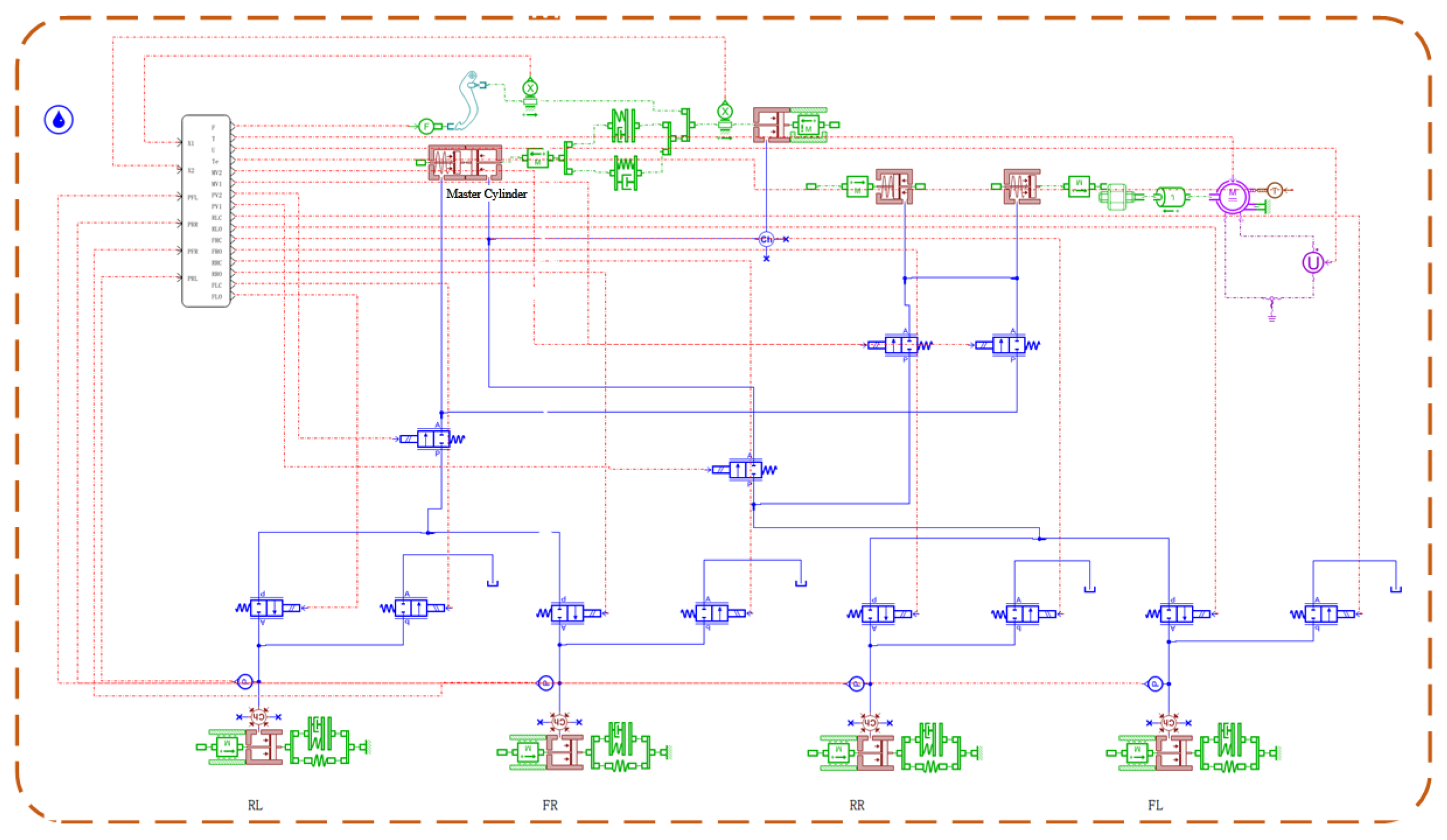
During the active braking process, the master cylinder isolation valve remains closed at all times, and the motor continuously provides pressure output to the booster cylinder. After the wheel cylinder fluid inlet valve opens, the brake fluid is rapidly injected into the wheel cylinder to complete the braking action. When entering the precise pressure regulation stage, the solenoid valve will flexibly adjust the opening degree of its valve port based on the real-time signals from the control unit, thereby ensuring that the wheel cylinder pressure can precisely match the dynamic changes in the target pressure. When the pressure of the wheel cylinder reaches the set standard, the inlet valve closes to maintain the stability of the system pressure. When the system needs to relieve pressure, the inlet valve remains closed, while the outlet valve switches to the open position. After the wheel cylinder has completed the pressure relief, the relevant solenoid valves all return to their initial working positions, waiting for the next command. The overall structure diagram of EHB is shown in Figure 1.
Figure 1.
Overall structure diagram of EHB. (The dashed lines represent the simplified connections of the sub-systems, and the symbol “M” denotes the motor.)
3. Modeling of the Electro-Hydraulic Braking System
To simplify the controller design while maintaining sufficient engineering accuracy, three main modeling assumptions are made in this study. First, the mechanical transmission is assumed to be a rigid body, neglecting material elasticity and friction; the resulting unmodeled dynamics are treated as lumped disturbances and actively compensated by the Extended State Observer (ESO) in the ADRC loop. Second, the hydraulic dynamics are assumed to be in an ideal state (isothermal and leak-free); this is acceptable because the pressure-building process of the EHB is extremely short, making the impact of these factors negligible. Finally, the target D-axis current of the motor is assumed to be zero (id = 0). Since the EHB motor primarily operates under low-speed and high-torque conditions, complex field-weakening control is unnecessary, and the inner PI current controller can easily and precisely maintain it at zero to ensure maximum torque output.
3.1. Permanent Magnet Synchronous Motor Model
The One-box system adopts surface-mount permanent magnet synchronous motor (PMSM) as the power source. To simplify the analysis process, idealized assumptions are made for the permanent magnet synchronous motor: (1) The influences brought by hysteresis loss, eddy current effect and core saturation during the motor operation process are not taken into account. (2) The magnetic field distribution generated by the rotor permanent magnets in the air gap and the electromotive force induced by the stator armature winding both exhibit standard sinusoidal wave characteristics. (3) When performing coordinate transformation, the constraint criterion is to keep the vector amplitude constant, and the transformation coefficient is set to 2/3. Based on the above assumptions, the mathematical model of the surface-mounted permanent magnet synchronous motor in a synchronous rotating coordinate system can be established. The specific derivation process is as follows.
First, the three-direction voltages ua, ub and uc of the motor a, b, and c are converted into two-phase voltages and through Clark transformation and expressed as:
After obtaining the two-phase voltage and in the stationary coordinate system, the voltage is then converted into the D-axis and Q-axis voltages of the motor in the rotating coordinate system through park transformation, denoted as ud and uq:
In the formula: is the electromechanical angle of the motor.
After transformation, the voltages of the D and Q axes of the motor in the rotor rotation coordinate system are:
In the formula: ud and uq are the D-axis and Q-axis components of the stator voltage respectively, R is the stator resistance, id and iq are the D-axis and Q-axis components of the stator electrical axis respectively, is the electrical angular velocity, and Ld and Lq are the D-axis and Q-axis components of the stator inductance respectively.
Because the inductance of the D and Q axes of the permanent magnet synchronous motor is affected by the current of the D and Q axes, for convenience and simplification, the motor model is modified. After ignoring the influence of core saturation and eddy currents, the inductance becomes a constant value. Then, the voltage equation after transformation is:
The torque equation is:
In the formula: Te represents the electromagnetic torque, pn represents the number of magnetic poles, and ψf represents the magnetic flux link of the permanent magnet.
Mechanical motion equation:
In the formula: J represents the equivalent moment of inertia, represents the mechanical angular velocity, TL represents the load torque, and TD represents the interference torque including damping, friction, disturbance, etc.
3.2. Transmission System Model
The transmission mechanism of the Electro-Hydraulic Braking system mainly consists of a reduction mechanism and a ball screw [29]. The reduction mechanism is responsible for reducing the output speed and increasing the torque of the motor, while the ball screw is responsible for converting rotational motion into linear motion.
The motion equation of the reduction gear is:
In the formula: T0 represents the output torque of the gear, Ti represents the input torque of the gear, and i represents the gear reduction ratio.
Ball screw motion equation:
In the formula: represents the angular displacement of the lead screw, xmc is the piston displacement of the servo cylinder, h0 is the lead of the ball screw pair, and ki is the transmission ratio.
Its torque equation:
In the formula: Td represents the driving torque, and Ft represents the output thrust.
3.3. Electric Master Cylinder Model
The motor pressure-building cylinder is a single-chamber hydraulic cylinder, with an additional liquid-replenishment tank. The brake fluid in the fluid-replenishment tank can only enter the hydraulic cylinder in one direction. The force model of the motor hydraulic cylinder is:
In the formula: mmc represents the mass of the piston in the motor pressure-building cylinder, xmc represents the displacement of the piston, pmc represents the internal pressure of the motor pressure-building cylinder, Amc represents the effective area of the piston, Ke represents the stiffness of the reset spring, and Ce represents the damping coefficient.
Its pressure change equation is
In the formula: Ve and Vb are respectively the brake fluid volumes of the main cylinder and the wheel cylinders.
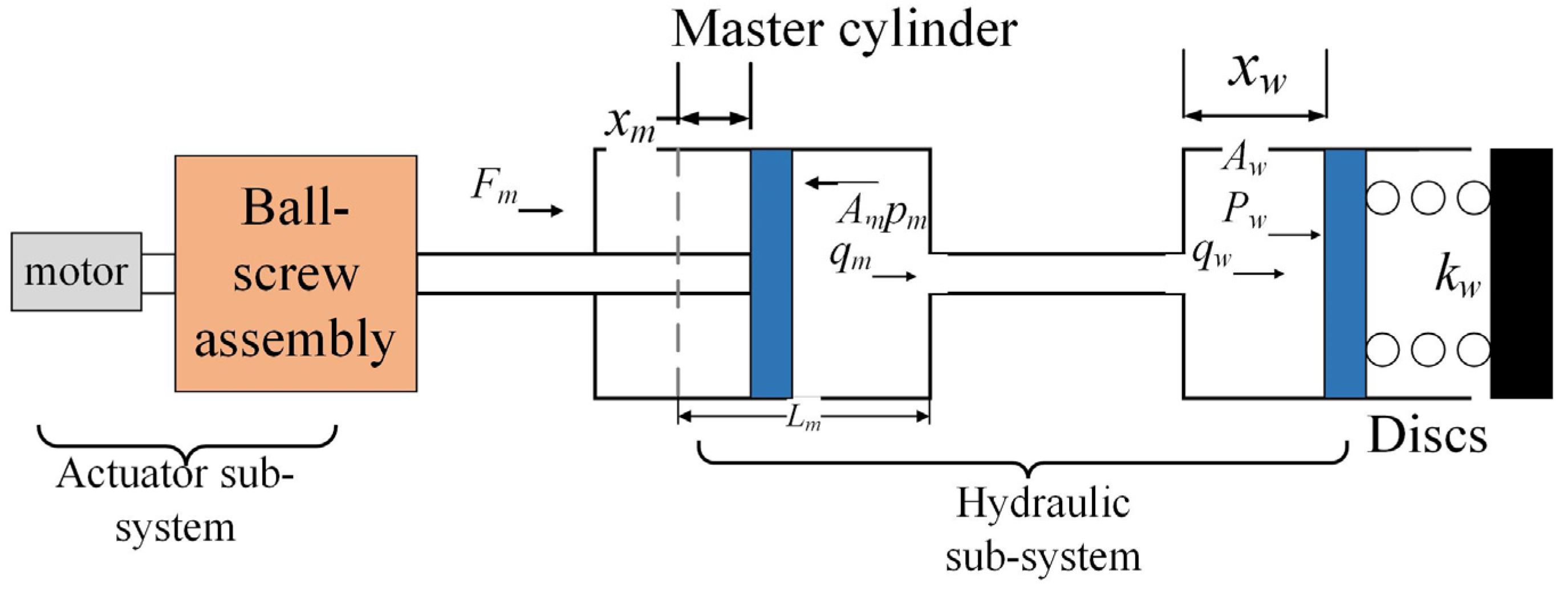
The EHB structure model is constructed as shown in Figure 2:
Figure 2.
Schematic diagram of the EHB model.
Derived from actual component selection an7d official manufacturer datasheets, the physical parameters of the EHB model established above are summarized in Table 1, providing a solid data foundation for subsequent controller design and validation.
Table 1.
Key physical parameters of the EHB system model.
4. Master Cylinder Pressure Control Strategy Based on the Electro-Hydraulic Braking System
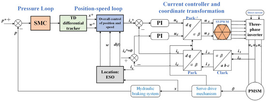
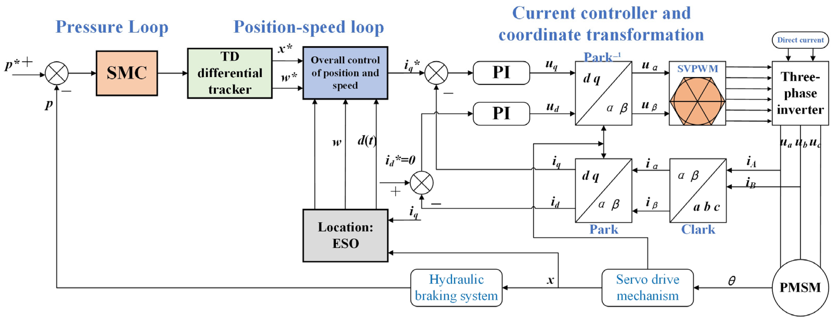
The pressure-building control strategy for permanent magnet synchronous motors proposed in this paper is shown in Figure 3, mainly including pressure loop controller, TD differential tracker, coordinate transformation, current controller, position–speed integrated controller, space vector pulse width modulation (SVPWM) and other modules. The overall planning of the motor controller is a three-loop control, namely the pressure loop, the position–speed loop, and the current loop. Firstly, a position–speed integrated controller is designed, which can not only synchronously consider the influence of motor speed and piston displacement, but also reduce problems such as reduced marginal benefits caused by multiple loops, and at the same time simplify the difficulty of system state observation. Through the integrated observer design, some mechanical and hydraulic uncertainties are synchronously observed as internal interference quantities of the system. Due to the strong nonlinear control performance of the Sliding Mode Controller, it is extremely suitable for pressure loop control in the system, and the pressure controller adopts Sliding Mode Control. The current controller adopts the classic PI control strategy.
Figure 3.
Logic block diagram of master cylinder pressure control. (where * denotes an alternative representation of the variable).
4.1. Design of Pressure Loop Control Strategy
The pressure loop is the outermost part of the Electro-Hydraulic Braking system. Through the calculation of the pressure loop, the target displacement of the motor piston can be obtained. After the displacement is transformed, the mechanical rotation angle and rotational speed of the motor can be obtained. First, the pressure variation equation of the master cylinder is processed. Ignoring the leakage of the fluid, the flow rate of the master cylinder is equal to that of the brake fluid in the wheel cylinders. Then, Equation (11) can be transformed into:
The pressure error ep is defined as the deviation between the desired and actual pressures, serving as the error input for the pressure sliding mode controller,
Design pressure Sliding Mode Control feedback controller:
In the formula: c1 and c2 are normal numbers. The magnitude of these values will affect the control quality and convergence speed of the system. If they are too large, it will cause system flutter; if they are too small, the convergence will be slow.
The exponential approach law is adopted, and a continuous and smooth hyperbolic tangent function is introduced to replace the signed function, in order to reduce the chattering of the system. Its expression is:
In the formula, both − and q are positive values, where tanh is a hyperbolic tangent function.
Ultimately, the control law is:
Therefore, the expected displacement of the piston is:
Construct the Lyapunov function:
In the formula: since q and ε are positive values, < 0. Therefore, the system is stable 0.
Furthermore, the global stability of the proposed cascaded multi-loop architecture is strictly guaranteed under the time-scale separation principle. Because the dynamic response speeds of these three control loops are inherently separated by orders of magnitude (the electromagnetic response of the current loop being the fastest, followed by the mechanical response of the motor, and the hydraulic response being the slowest), the inner control loops reach their steady states almost instantaneously from the perspective of the outer loop. Consequently, they can be treated as ideal equivalent proportional gains with minor phase lag. Crucially, this time-scale separation framework rigorously incorporates the intrinsic nonlinear hydraulic dynamics, fluid compressibility variations, and unmodeled valve characteristics—which were simplified in Equations (19) and (20)—into the global stability analysis. Within this multi-loop cascaded system, these complex mechanical and hydraulic nonlinearities are formulated as a lumped dynamic disturbance, which is actively estimated and compensated for in real-time by the middle-loop Extended State Observer (ESO). Since the faster-operating inner loop ensures the rapid convergence of the disturbance estimation error, the propagation of hydraulic nonlinearities into the pressure loop is strictly restricted. Therefore, the negative definiteness of the Lyapunov derivative is maintained, ensuring the asymptotic stability of the entire cascaded EHB system without causing mutual interference among the loops.
4.2. The Position Loop and the Speed Loop Are Uniformly Controlled
To address issues such as hydraulic disturbance, mechanical friction, and imprecise control of solenoid valves in hydraulic systems, this section proposes a unified control algorithm based on Active Disturbance Rejection Control (ADRC) that integrates the position loop and speed loop.
The core of ADRC’s ability to effectively enhance the system’s anti-interference performance lies in taking the simple integral series form as the standard type, integrating the parts of the system that deviate from this standard type into the total disturbance, conducting real-time estimation of the total disturbance through the design of an Extended State Observer, and then implementing compensation through the output of the control law. Eventually, the system disturbance is equivalent-transformed, thereby forming a simple integral series structure. Simplify the overall design process of the control system. The following takes a single-input single-output system as an example:
If the above formula is converted to the standard type, the design input is , and the actual control quantity is:
However, the uncertainty of model parameters can weaken the performance of such control strategies based on precise models. However, the design concept of transforming the system into a standard type still holds significant reference value. Active Disturbance Rejection Control (ADRC) can be understood as a “dynamic compensation linearization” method. The design core of this control strategy mainly depends on two aspects: one is how to accurately obtain the disturbance information during the operation process, and the other is how to reasonably design the virtual equivalent input to achieve high dynamic response control.
To achieve strong anti-disturbance performance of the system, the core lies in precisely extracting disturbance signals from the controlled output quantity and making targeted compensations in the control law, thereby offsetting the adverse effects brought by uncertain disturbances [30]. The Extended State Observer (ESO) has the ability to observe the total disturbance of the system. Its core working mechanism is to use the actual output y of the system and the control quantity u to track and estimate the state variables and disturbance quantities of the system in real time. The form is as follows:
In the formula: y(k) represents the output of the system, z1 and zn are the state observations of the system, and e(k) is the system output and estimation.
The output error, zn+1, is the state variable estimated by the system, β01, β02, …, β0(n+1) is the observer parameter, fi(e) is the function of the observation error of the output value, i = 1, 2, … n. In particular, when f is a linear function, the observer is a linear observer; when f is nonlinear, the observer is a nonlinear observer.
- (1)
- TD tracker
To suppress the oscillation and overshoot of the master cylinder piston during its movement, which may lead to piston impact and unstable pressure, a tracking differentiator based on the fhan function is adopted here for displacement control. Its function expression is:
In the formula: x1 and x2 are output variables, r and h are adjustment parameters, u0 is the displacement control law, and the others are intermediate variables.
From Equation (24), the following formula can be obtained. In this way, both the differential signal of position and the differential signal of rotational speed can be obtained.
In the formula: represents the expected displacement of the electric cylinder piston, and are respectively the actual piston displacement and the actual rotational speed of the motor within the NTH cycle during the position-tracking process.
- (2)
- Integrated control of position and speed based on active disturbance rejection
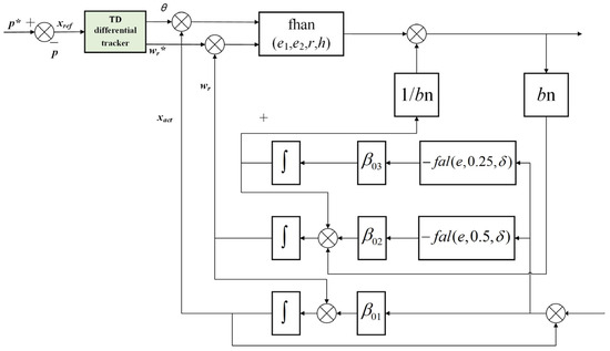
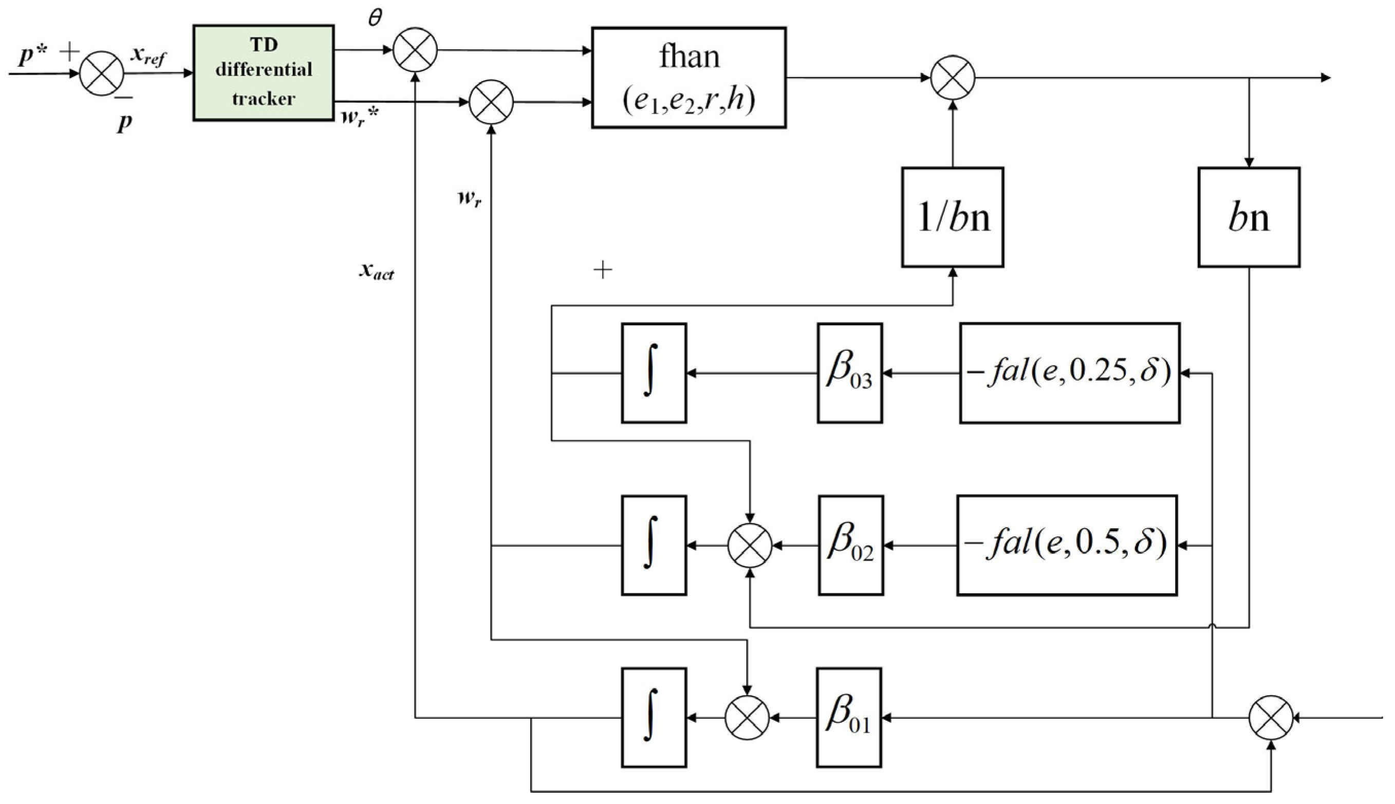
The internal disturbances of the servo system mainly include the Q-axis current control error of the current inner loop, the perturbation of moment of inertia, the perturbation of flux linkage parameters, PMSM cogging torque, viscous friction, and the nonlinear static friction force of the motor shaft, etc. The external disturbances are mainly caused by the internal pressure and hydraulic oscillation changes in the hydraulic system. Therefore, incorporating the piston displacement and motor speed into an integrated control framework enables real-time observation and control compensation of internal disturbances in the mechanical system through an Extended State Observer. At the same time, it can avoid the complex modeling process of the friction model and effectively reduce the complexity of the control system. The overall control logic is shown in Figure 4.
Figure 4.
Integrated control logic for position and speed.
To achieve precise control of displacement, it is necessary to dynamically estimate the total disturbance of the system based on the electrical angle of the motor and the Q-axis current. Therefore, the following ESO observer is designed
In the formula: and are the estimated values of the piston displacement and electrical angular velocity in the KTH operation period, respectively. ex is the observation error of the piston displacement, fal is a nonlinear function, β01, β02, and β03 are the observer coefficients, and h1 is the control period of the position loop. In particular, β01 affects the tracking output speed of ESO. The larger the β01, the faster the speed. β02 affects the speed at which ESO tracks the output differential. The larger β02, the faster the speed. β03 mainly affects the accuracy of the system. If β03 is too small, the estimated speed of disturbances will slow down; if β03 is too large, oscillations will occur, leading to unstable phenomena.
bn is the nominal value of the input coefficient, and its expression is:
The definition of the fal function is as follows:
In the formula: represents the error threshold, sign is the sign function, and α is the parameter. represents a linear interval. When , the fal function is nonlinear. When , the fal function is also nonlinear. The purpose is to suppress the oscillation caused by high gain under small errors.
- (3)
- NELESS nonlinear error compensation control law
Based on the properties of the fhan function, the following linear control law is designed, including piston displacement error, rotational speed error, and disturbance compensation feedback control. The fhan function is utilized to achieve integrated control of rotation angle and rotational speed in a loop, simplifying the control loop of the motor and reducing control losses due to loop transmission.
Among them: c, r, and k are control parameters, and h is the control period.
4.3. Design of Current Loop Control Strategy
From Equation (4), it can be seen that in the voltage equation, there is a coupling between the D-axis and Q-axis currents, there is a cross-coupling electromotive force term in the D-axis voltage and Q-axis voltage. This indicates that the D-axis voltage ud of the motor is affected by both the D-axis current and the Q-axis current, and the same applies to the Q-axis. The flux linkage of the motor stator is proportional to the angular velocity. When the motor speed is high, the current control will be disturbed. Therefore, the voltage decoupling equation is adopted here, which is:
Among them: and are the voltage equations of the D and Q axes of the motor after feedforward compensation and and after transformation are:
After feedforward decoupling, the D and Q axes of the compensated motor no longer have the aforementioned voltage coupling phenomenon, and at the same time, the electrical angular velocity term is eliminated, facilitating subsequent control.
At the same time, error PI control is adopted here. Combined with Equation (31), the control equation is:
4.4. Parameter-Tuning Methodology and Core Configurations
This paragraph explicitly elaborates on the parameter-tuning methodology and specific procedure employed during the design of the proposed cascaded control algorithm in Section 4. In actual real-vehicle EHB deployment, utilizing pure mathematical global optimization algorithms (e.g., Genetic Algorithms) is highly prone to generating aggressive and high-frequency control commands during the early stages of iterative optimization. This phenomenon can induce severe hydraulic chattering, posing a substantial risk of damaging physical mechanical actuators. Therefore, to guarantee hardware safety and enhance the engineering reproducibility of the control strategy, the core parameters in this study are systematically determined through a sequential heuristic tuning method based on stability constraints and time-scale separation. The tuning procedure is carried out sequentially from the innermost loop to the outermost loop based on the principle of time-scale separation. First, the innermost current loop (PI controllers) is analytically tuned via the pole-zero cancelation method derived from the inherent electrical time constant of the drive motor. Second, to eliminate blind trial-and-error, the middle position–speed loop (ADRC) utilizes the well-established bandwidth parameterization method, which mathematically maps the multiple observer gains (β01, β02, β03) of the ESO into a single physical variable: the observer bandwidth (), thereby drastically reducing the parameter-tuning dimension. Finally, the parameters of the outermost pressure loop (SMC) are tuned under strict theoretical stability criteria. Specifically, as derived in the Lyapunov stability analysis, the robust switching gain (q) is configured to be marginally greater than the supremum of the residual estimation error from the middle-loop ESO. This cascaded framework—combining active compensation from the ESO with the robust boundary coverage of the SMC—endows the overall closed-loop system with extremely low sensitivity to internal tuning uncertainties, ensuring a sufficient stability margin against both external disturbances and physical parameter perturbations. The final configurations of the core control parameters are summarized in Table 2 below.
Table 2.
Key control parameters of the proposed cascaded architecture.
5. Simulation and Experimental Research on Master Cylinder Pressure Control Strategy of the Electro-Hydraulic Braking System
The previous text completed the modeling of the Electro-Hydraulic Braking system and the master cylinder pressure control strategy. This chapter mainly conducts simulation analysis and experimental verification on the control algorithm proposed in the previous text. First, build a joint simulation platform based on Matlab/Simulink (R2021a) and AMESim. The joint simulation process mainly involves Matlab/Simulink receiving the pressure and motor signals output by AMESim in real time. After calculation, the control signals of the motor and solenoid valve are output to AMESim. After execution by AMESim, feedback is sent back to form a closed-loop control. The simulation model is shown in Figure 5. Subsequently, a real-vehicle experiment using the One-box system was carried out. By conducting some typical working condition tests on the real vehicle equipped with the equipment, the dynamic response of the vehicle was observed to verify the performance of the control algorithm.
Figure 5.
AMESim simulation model diagram.
5.1. Simulation of Master Cylinder Pressure Control in the Electro-Hydraulic Braking System
In this section, a joint simulation scheme of Matlab/Simulink and AMESim is adopted to conduct pressure following control simulation tests on the motor pressure-building cylinder, in order to verify the practical effectiveness of the proposed rapid-pressure-building strategy for permanent magnet synchronous motors. Set step, slope and sinusoidal pressure signals as the three types of target signals for this pressure following the control experiment, and test the pressure following the control effect of the motor pressure-building cylinder through these three types of signals. To comprehensively evaluate the control performance of the proposed strategy under various dynamic inputs, three key quantitative metrics—tracking error, maximum tracking error, and steady-state error—are introduced as the evaluation baseline. Specifically, the tracking error is defined as the instantaneous difference between the target reference pressure and the actual master cylinder pressure. The maximum tracking error represents the peak absolute deviation captured during the entire transient process. The steady-state error is defined as the average absolute deviation calculated after the system response enters and stabilizes within a designated error band (e.g., ±5%) of the final target value.
- (1)
- Step pressure control test
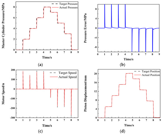
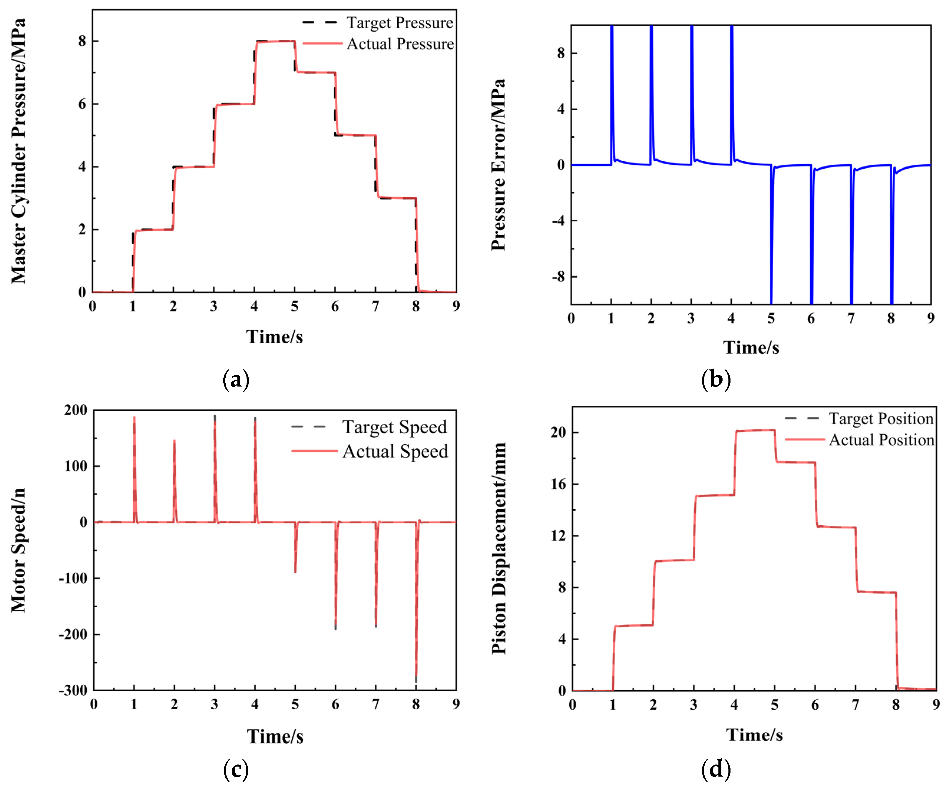
To test the following effect of the master cylinder control strategy on pressure when a sudden pressure change occurs, the following working conditions were tested: Firstly, the pressurization control was carried out, with the pressure changing according to 2 MPa, 4 MPa, 6 MPa, and 8 MPa. Then, the depressurization control was implemented, with the pressure changing according to 7 MPa, 5 MPa, and 3 MPa in 0 steps. The following are the test results, as shown in Figure 6. During the pressurization process, this control algorithm has a good control effect on the target pressure, with almost no overshoot or buffering. It reaches the target pressure with a delay of approximately 0.05 s and then quickly maintains stability. Except for when there is a sudden pressure change and the pressure error is relatively large, the rest remain within 0.1 MPa. The motor speed and piston displacement can well follow the target speed and target displacement, and there is basically no jitter or overshoot, with a good control effect. This pressure control algorithm is effective.
Figure 6.
Simulation results of step pressure control in the master cylinder: (a) pressure-following curve; (b) pressure-following error curve; (c) motor speed follows the curve; (d) the piston displacement follows the curve.
- (2)
- Sinusoidal pressure-following test
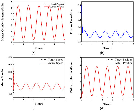
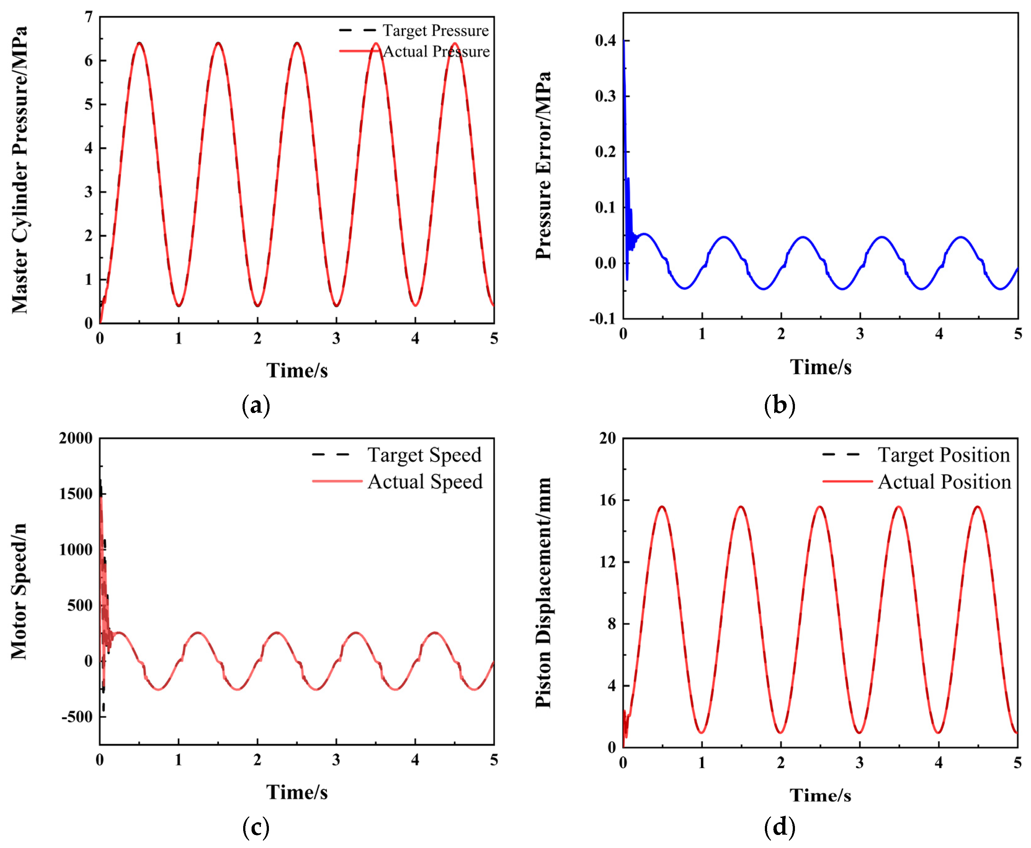
To test the following effect of the master cylinder pressure-control strategy on pressure when the pressure signal continuously changes, the control signal is: offset 3.4 MPa, amplitude 3 MPa, frequency 1 Hz. The test results are shown in Figure 7. The actual pressure of the electric master cylinder has a good following effect on the sinusoidal target pressure, with basically no overshoot. There is a slight jitter at the beginning of the pressure rise, but it has little impact on the subsequent pressure control. Consider the possible influence of hydraulic vibration. Under the control of this master cylinder control algorithm, the motor speed rapidly rises to 1700 RPM, quickly eliminating the idle stroke of the piston and rapidly building pressure to follow the target pressure. The maximum pressure-following error shall not exceed 0.5 MPa, and when stable, the pressure error is less than 0.1 MPa. Moreover, the motor speed has no jitter or overshoot, and the piston position can always follow the target position with a small error. It indicates that the control algorithm is effective under this working condition.
Figure 7.
Simulation results of master cylinder sinusoidal pressure control: (a) pressure-following curve; (b) pressure-following error curve; (c) motor speed follows the curve; (d) the piston displacement follows the curve.
- (3)
- Pressure growth rate control test
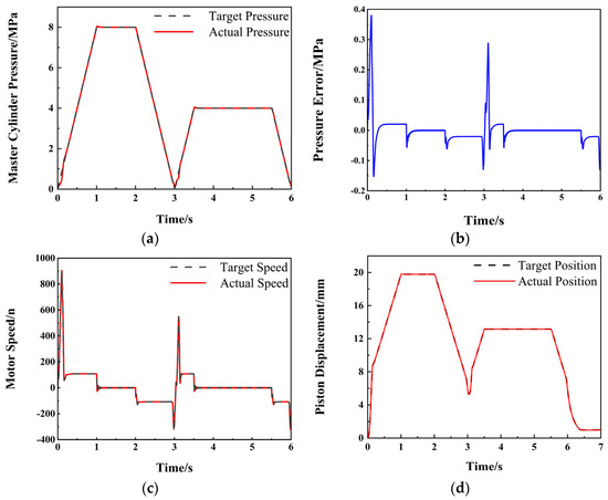
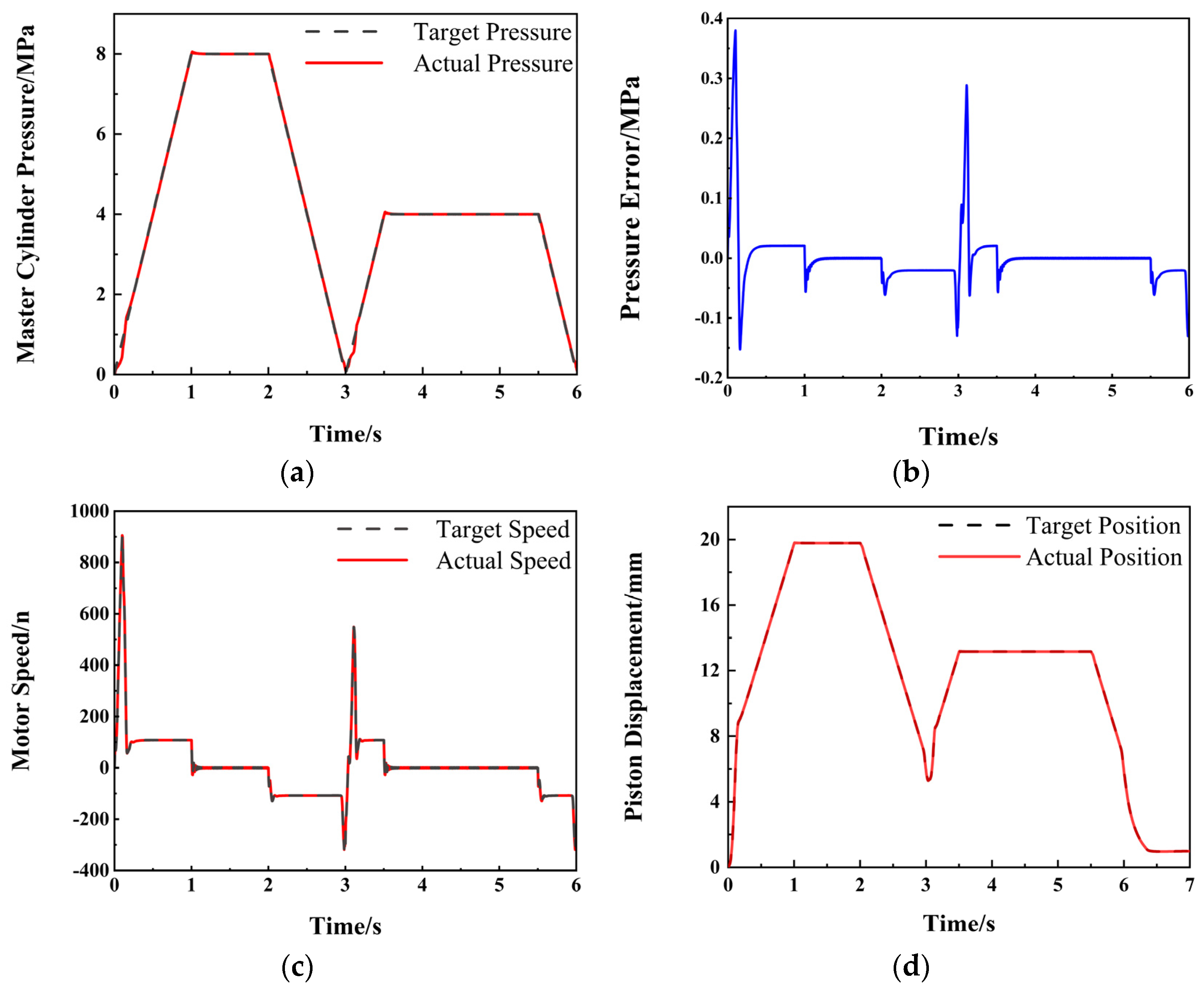
To verify the control ability of the master cylinder pressure control algorithm over the pressure growth rate, two pressure signals were designed. The pressure was raised to 8 MPa within 1 s, held for 1 s, then released to 0 within 1 s, and then rapidly raised to 4 MPa within 1 s, held for another 1 s, and then released to 0. The test results are shown in Figure 8.
Figure 8.
Simulation results of master cylinder pressure control: (a) pressure-following curve; (b) pressure-following error curve; (c) motor speed follows the curve; (d) the piston displacement follows the curve.
The experimental results show that at the initial stage of pressure increase, there will be a slight lag in pressure, and then the error is quickly eliminated to follow the target pressure. Throughout the entire process, the pressure error does not exceed 0.4 MPa. The pressure error generally occurs at the moment of sudden pressure changes, and when the pressure is stable, the error is within 0.1 MPa. The figures respectively show the piston displacement-following curve and the rotational speed curve. The motor’s maximum rotational speed is 900 RPM. When receiving the boost signal, the motor’s rotational speed can rise rapidly, maintaining the master cylinder pressure following the target pressure. Throughout the entire control process, the piston displacement always closely follows the target value. It is clear that this control algorithm has a better control ability under this working condition.
- (4)
- Comparative Simulation Analysis and Robustness Evaluation with Benchmark Controllers
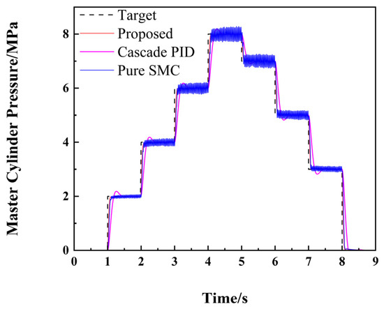
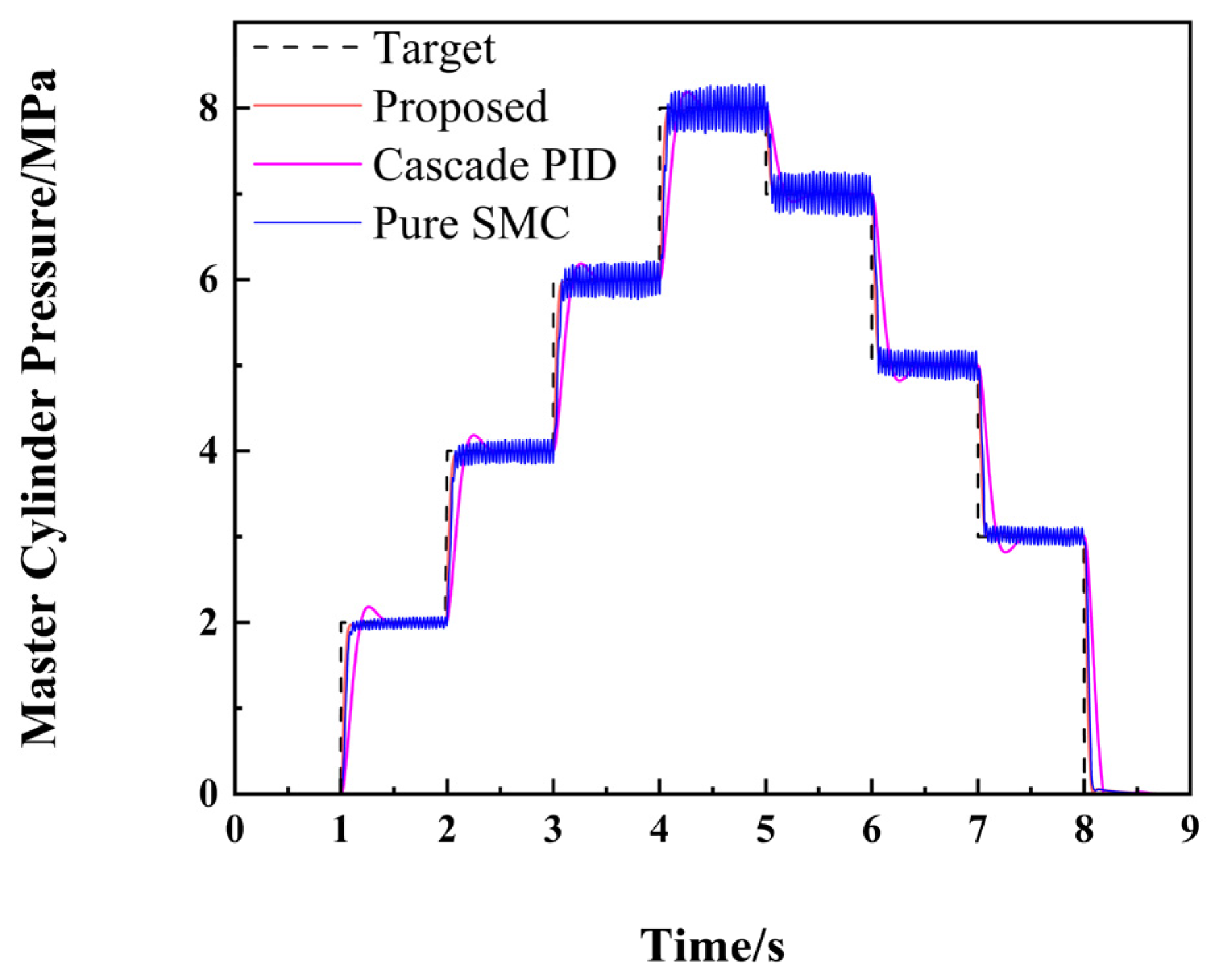
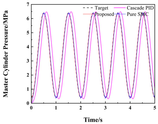
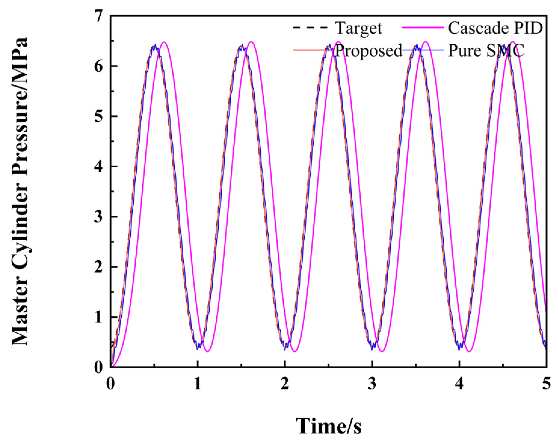
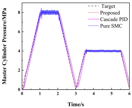
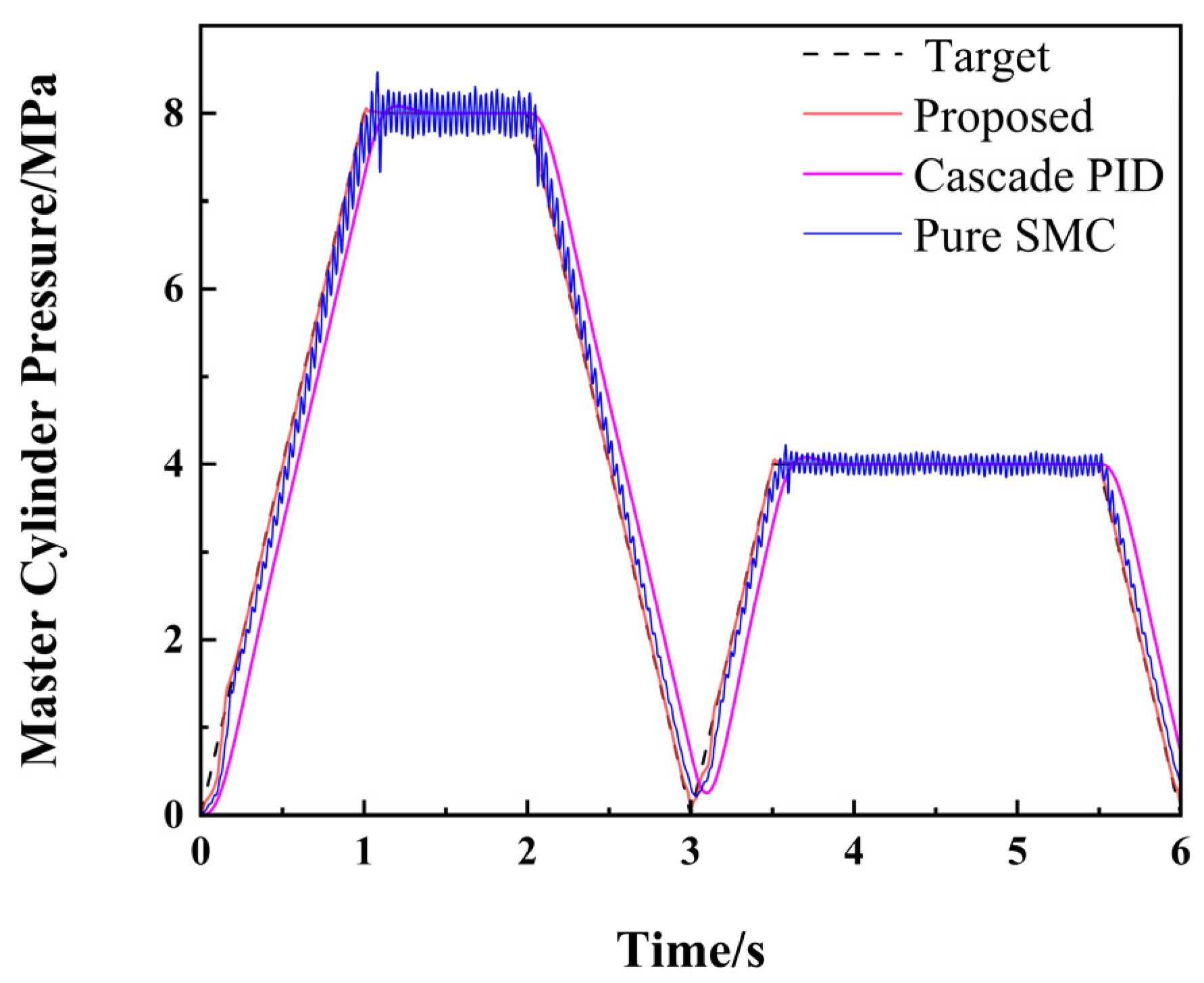
To comprehensively evaluate the advanced nature of the proposed control strategy, this section introduces the traditional PID control strategy and the pure Sliding Mode Control (SMC) strategy as benchmark methods for comparison under the identical step, sinusoidal, and pressure growth rate conditions. The master cylinder pressure-following curves of the three control strategies are presented in Figure 9, Figure 10 and Figure 11, respectively.
Figure 9.
Comparison of pressure-following curves among different control strategies under the step pressure control test.
Figure 10.
Comparison of pressure-following curves among different control strategies under the sinusoidal pressure-following test.
Figure 11.
Comparison of pressure following curves among different control strategies under the pressure growth rate control test.
In the pressure curve comparison under the step pressure control test (Figure 9), the target pressure exhibits a step-like sudden change. The results demonstrate that the proposed strategy exhibits the optimal transient and steady-state responses, rapidly following the target curve with a response delay of only 0.05 s and absolutely no overshoot. In contrast, the traditional PID strategy suffers from severe overshoot due to integral windup inertia, with its maximum pressure peak reaching approximately 8.2 MPa. Although the pure SMC strategy responds quickly, it experiences severe high-frequency chattering upon entering each steady-state pressure-holding plateau due to the absence of dynamic compensation from the Extended State Observer (ESO) for the nonlinear hydro-mechanical coupling disturbances.
In the pressure-following curve comparison under the sinusoidal pressure-following test (Figure 10), the traditional PID strategy produces extremely severe phase lag and amplitude attenuation, constrained by the nonlinear hysteresis and integral lag effects of the hydraulic system. While the pure SMC strategy mitigates the delay to a certain extent, its curve exhibits extremely rough and blurred strong chattering band characteristics, accompanied by a dynamic waveform error of approximately ±0.4 MPa. In contrast, the curve of the proposed strategy is smooth and fine, nearly overlapping with the target dashed line, and strictly confines the maximum dynamic error of the entire cycle to within ±0.1 MPa, fully demonstrating its high robustness against dynamic disturbances.
Finally, in the pressure curve comparison under the pressure growth rate control test (Figure 11), the traditional PID strategy once again exceeds the target peak and exhibits a noticeable overshoot phenomenon at the turning points of 1 s and 3.5 s due to its sluggish tracking response. The pure SMC strategy exhibits significant tracking lag during the inclined-ramp-climbing phase and severe high-frequency chattering during the pressure-holding periods. The control strategy proposed in this paper achieves smooth transitions at all points of sudden slope changes, with minimal chattering during the pressure-holding periods, perfectly balancing the rapidity of the braking response and the robustness of the algorithm.
5.2. Experimental Study on Master Cylinder Pressure Control of the Electro-Hydraulic Braking System
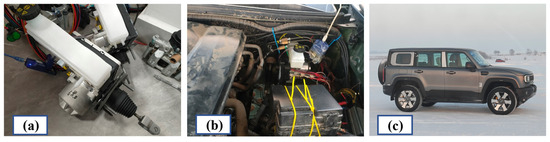
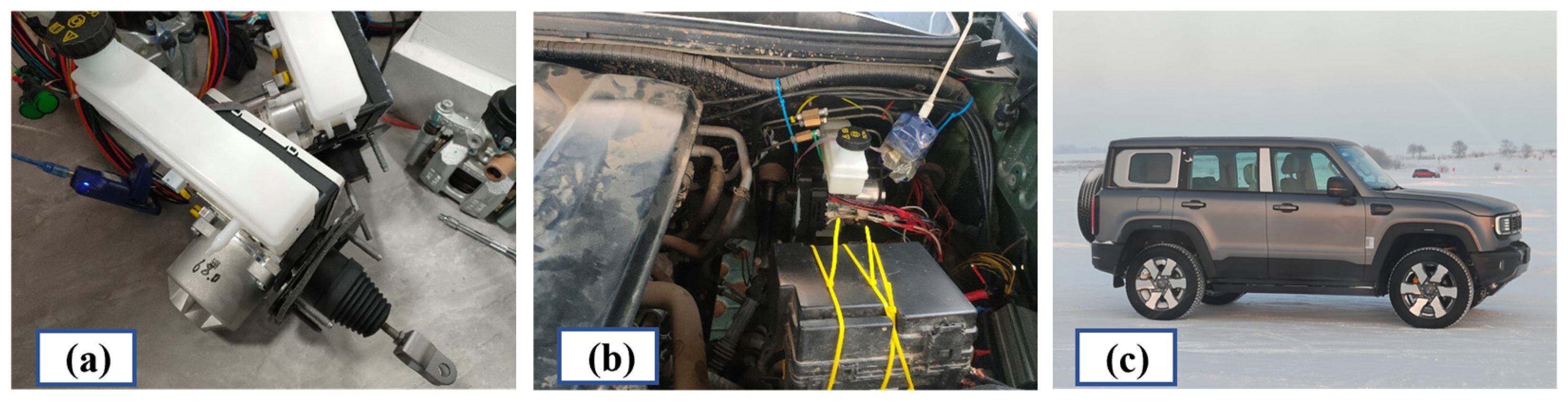
In order to deeply verify the effectiveness of the proposed control strategy of the Electro-Hydraulic Braking system, real vehicle tests were carried out based on the One-box experimental vehicle in this chapter. The experiment focuses on testing the motion characteristics of vehicles under typical working conditions such as longitudinal emergency braking and lateral critical instability. The performance of the control algorithm was comprehensively verified by designing experimental scenarios that could fully reflect the dynamic response of the vehicle. In the real vehicle test experiment, the upper computer writes the control algorithm to the vehicle controller equipped with the Electro-Hydraulic Braking system through the downloader. At the same time, the Vector product for data monitoring decodes and visually analyzes the obtained vehicle information, braking pressure, etc. The test platform, original components and actual vehicles of the relevant experiments are shown in Figure 12.
Figure 12.
Real vehicle test platform: (a) One-box original components; (b) One-box installation location; (c) One-box real vehicle.
During the real-vehicle tests, the control algorithm is flashed from the host computer into the vehicle controller of the EHB system via a downloader. Simultaneously, Vector data acquisition tools are utilized to decode and visually analyze the real-time vehicle states and braking pressure. The key parameters of the test vehicle equipped with the One-box system are summarized in Table 3. To ensure the reliability and repeatability of the experimental data, each real-vehicle test scenario (including both ramp and sinusoidal tracking conditions) was independently repeated five times under identical initial conditions. The continuous error curves and quantitative boundaries (such as steady-state error and maximum tracking error) presented in the subsequent analyses were statistically extracted from the average values of these repeated trials.
Table 3.
Key parameters of the test vehicle.
5.2.1. Pressure Tracking Experiments Under Ramp Input Conditions
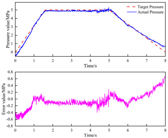
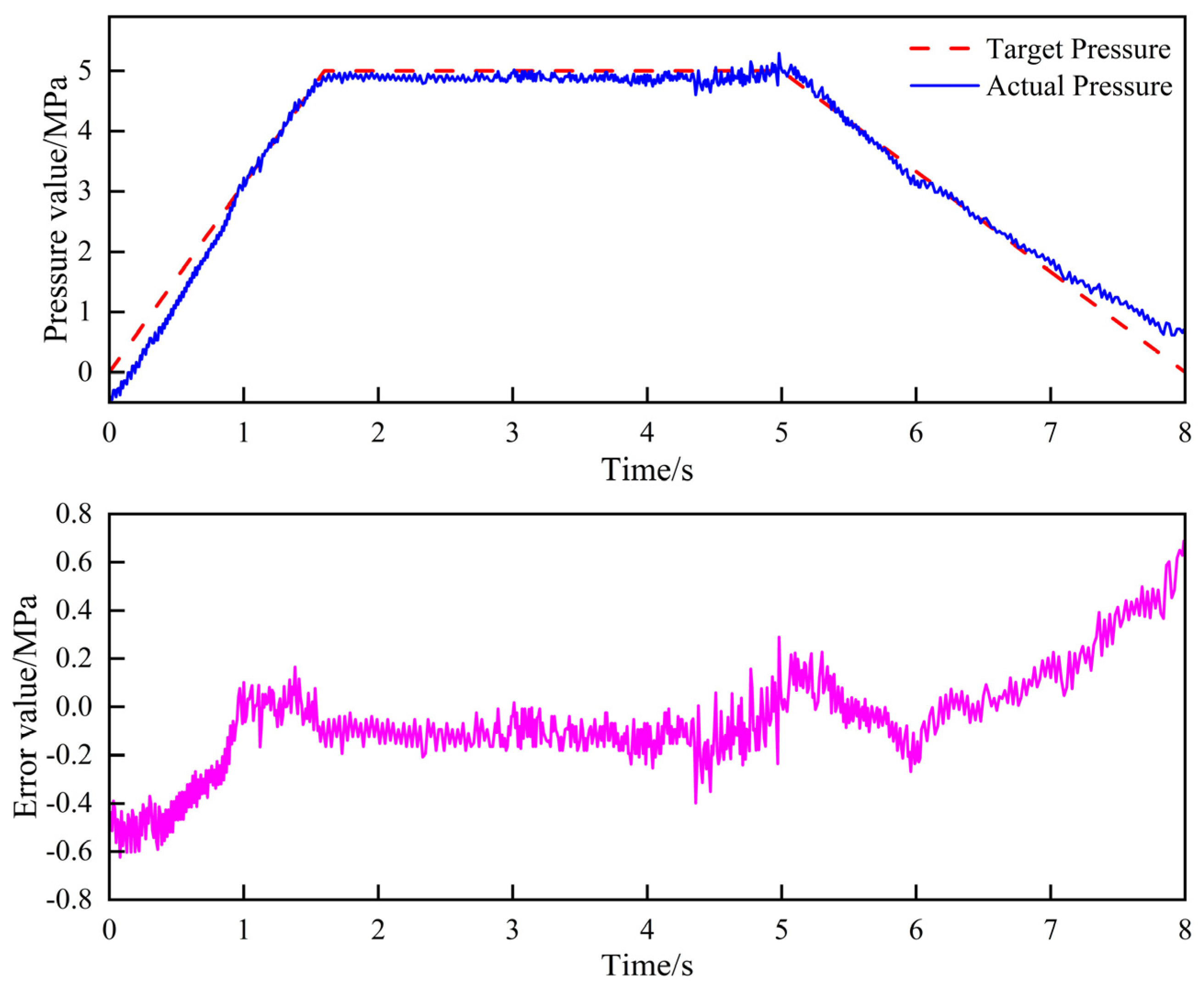
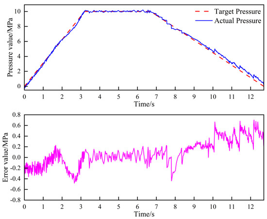
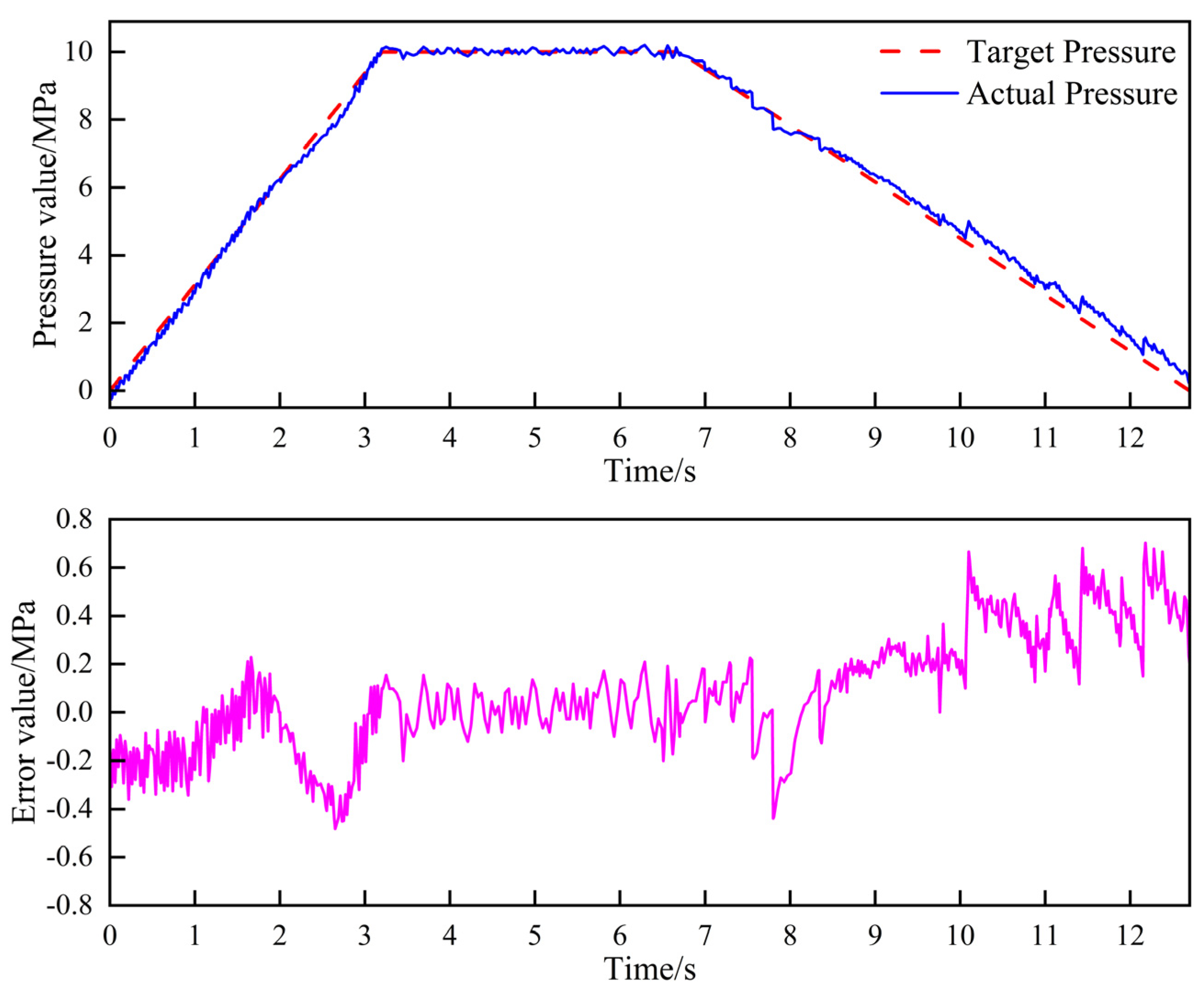
This section defines the test scenario for ramp pressure tracking. The experiment specifies peak target pressures of 5 MPa and 10 MPa. During the pressurization phase, the target pressure rise rate is configured at 3.5 MPa/s. Once the pressure reaches the target peak, a holding phase of 3.5 s is maintained, followed by depressurization until the target pressure returns to 0 MPa. The corresponding results are presented in Figure 13 and Figure 14. It should be noted that the target peak pressure in the real-vehicle trials was restricted to 10 MPa primarily due to operational safety and experimental accuracy considerations. Under our specific experimental vehicle conditions and track states, a master cylinder pressure exceeding 10 MPa could potentially induce wheel lock-up, thereby triggering the Anti-lock Braking System (ABS). Continuous ABS interventions would cause vehicle skidding during the tests, introducing severe operational risks and compromising the accuracy and consistency of the experimental data. Nevertheless, the tracking capability of the proposed algorithm does not degrade under high pressures; its theoretical robustness and accuracy bounds under high-pressure conditions are significantly higher than this specified trial value.
Figure 13.
Pressure-tracking curves and error plots for a target peak pressure of 5 MPa.
Figure 14.
Pressure-tracking curves and error plots for a target peak pressure of 10 MPa.
5.2.2. Pressure-Tracking Experiments Under Sinusoidal Conditions
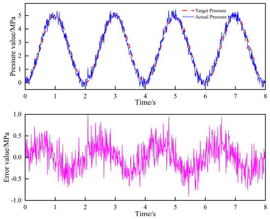
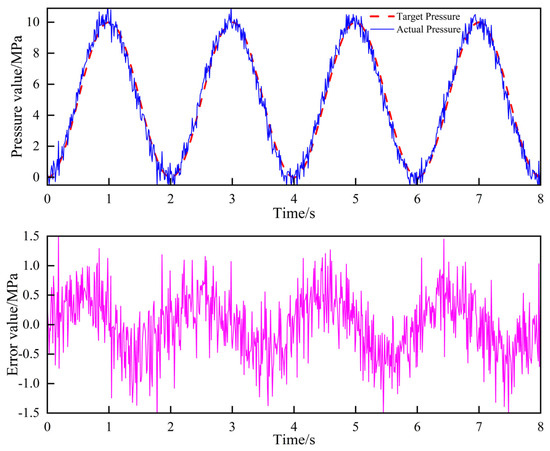
This section outlines the test scenarios for sinusoidal pressure tracking. The experimental parameters were configured with target pressure amplitudes of 5 MPa and 10 MPa at a frequency of 0.5 Hz. The corresponding results are presented in Figure 15 and Figure 16.
Figure 15.
Pressure-tracking curves and error plots for a target pressure amplitude of 5 MPa.
Figure 16.
Pressure-tracking curves and error plots for a target pressure amplitude of 10 MPa.
As observed in the results, under the 5 MPa low-pressure condition, the actual pressure tracks the target trajectory closely with minimal phase lag. The tracking error is maintained within ±0.5 MPa during steady-state operation, demonstrating excellent low-frequency response characteristics. When the target amplitude was doubled to 10 MPa, the phase lag increased slightly due to the heightened nonlinearity and fluid damping inherent in the hydraulic system. However, the system exhibited no significant amplitude attenuation or oscillation. In this scenario, the tracking error remained consistently within ±1.2 MPa. These findings confirm that the proposed control strategy possesses superior controllability and robustness, effectively overcoming system inertia under high-pressure conditions while ensuring stable tracking accuracy across varying pressure ranges.
6. Conclusions
- (1)
- This paper conducts an in-depth study on the configuration analysis and control strategy of the Electro-Hydraulic Braking system. Firstly, through a simple analysis of the EHB of the two configurations, the One-box configuration is selected as the research object. Then, the mathematical models of the key components of the permanent magnet synchronous motor, transmission mechanism and electric master cylinder were established, laying a theoretical foundation for the subsequent research.
- (2)
- A set of hierarchical control schemes was proposed in the aspect of master cylinder pressure control. This scheme adopts a three-loop control strategy, optimizing from three levels: the pressure loop, the position–speed loop, and the current loop. The pressure loop adopts a Sliding Mode Control algorithm, combined with a specific approach law and function optimization, to ensure system stability and precisely control piston displacement. The position–speed loop is based on an improved Active Disturbance Rejection Control, and precise control is achieved by using a TD differential tracker and a third-order extended observer. The current loop eliminates interference through the voltage decoupling equation and adopts error PI control.
- (3)
- A co-simulation platform based on Matlab/Simulink and AMESim was established to comprehensively evaluate the proposed rapid pressure buildup control strategy for the master cylinder. Simulation results indicate that the pressure error remains below 0.1 MPa during steady states and does not exceed 0.4 MPa during abrupt pressure transients. Subsequently, vehicle-level pressure tracking tests were conducted using a vehicle equipped with the One-box system. The experimental results demonstrate that under ramp input conditions, the steady-state control error is consistently maintained within ±0.2 MPa, with a maximum tracking error kept within 0.8 MPa; under sinusoidal conditions, the steady-state error stabilizes within ±0.5 MPa, while the maximum tracking error remains under 1.2 MPa. These findings validate the superior reliability and robustness of the proposed control algorithm.
Although this study focuses on robust pressure tracking at the actuator level, evaluating the overall motor power consumption and energy recovery efficiency integrated with upper-layer braking force distribution strategies is highly meaningful. Additionally, conducting more comprehensive testing under temperature variations, parameter uncertainties, and external disturbances to further verify the algorithm’s robustness is also essential. These subjects remain critical directions for our future research and experimental validation within the entire braking system.
Author Contributions
Conceptualization, X.H. and J.Z.; methodology, X.H.; software, X.H. and H.M.; validation, X.H. and H.M.; formal analysis, X.H.; investigation, Y.Y. and D.P.; resources, X.H.; data curation, J.Z. and Y.Y.; writing—original draft preparation, X.H.; writing—review and editing, J.Z. and H.M.; visualization, J.Z.; supervision, Y.Y. and D.P.; project administration, Y.Y. and D.P.; funding acquisition, J.Z. and Y.Y. All authors have read and agreed to the published version of the manuscript.
Funding
This research was funded by the Project of National Natural Science Foundation of China (52202480) and Hubei Provincial Key Research and Development Program Project (2024BAB083).
Data Availability Statement
Since the research project described in this article is ongoing, the experimental datasets generated during the study are temporarily unavailable. However, some of the used datasets have been made publicly available for sharing. Interested researchers may contact the corresponding author via institutional email for inquiries regarding specific technical implementations, including model architecture details or critical layer configurations.
Acknowledgments
We sincerely thank our advisor and fellow lab members for their tremendous support and guidance throughout the writing of this paper and the experimental validation. Finally, we are deeply grateful to the anonymous reviewers for their insightful comments and constructive suggestions.
Conflicts of Interest
Dongkai Pan is an employee of Voyah Automotive Technology Co., Ltd. The remaining authors declare that the research was conducted in the absence of any commercial or financial relationships that could be construed as a potential conflict of interest.
References
- Oshima, T.; Fujiki, N.; Nakao, S.; Kimura, T.; Ohtani, Y.; Ueno, K. Development of an Electrically Driven Intelligent Brake System. SAE Int. J. Passeng. Cars—Mech. Syst. 2011, 4, 399–405. [Google Scholar] [CrossRef] [Scilit]
- Feigel, H.J. Integrated brake system without compromises in functionality. ATZ Worldw. 2012, 114, 46–50. [Google Scholar] [CrossRef] [Scilit]
- Lin, X. R&D and Industrialization of Key Technologies for WCBS Integrated Wire-Controlled Brake System; Wuhu Bethel Automotive Safety Systems Co., Ltd.: Wuhu, China, 2023. (In Chinese) [Google Scholar]
- Zhang, J. Design and Experimental Study on Solenoid Valve of Commercial Vehicle Electro-Hydraulic Braking System. Master’s Thesis, Yanshan University, Qinhuangdao, China, 2024. (In Chinese) [Google Scholar] [CrossRef]
- Todeschini, F.; Corno, M.; Panzani, G.; Savaresi, S.M. Adaptive position–pressure control of a brake by wire actuator for sport motorcycles. Eur. J. Control 2014, 20, 79–86. [Google Scholar] [CrossRef] [Scilit]
- Wei, L.; Liu, Y.; Wang, X.; Liu, Z.; Li, L. Pressure Control Strategy of Brake-by-Wire System Based on Hierarchical Control. J. Mech. Eng. 2024, 60, 487–496. (In Chinese) [Google Scholar] [CrossRef] [Scilit]
- Chen, Z.; Zhu, B.; Zhao, J.; Wu, J. Multi-closed-loop Pressure Control Strategy Considering Nonlinear Characteristics of Electro-booster Brake System. J. Mech. Eng. 2023, 59, 190–198. (In Chinese) [Google Scholar] [CrossRef] [Scilit]
- Jian, Z.; Chen, Z.; Bing, Z.; Wu, J. Precise Active Brake-Pressure Control for a Novel Electro-Booster Brake System. IEEE Trans. Ind. Electron. 2020, 67, 4774–4784. [Google Scholar] [CrossRef] [Scilit]
- Jiang, L.; Shi, Q.; Wei, Y.; He, Y.; He, Z.; He, L. Electro-hydraulic braking dynamics for pressure demand control of brake-by-wire system. Proc. Inst. Mech. Eng. Part D J. Automob. Eng. 2024, 238, 735–748. [Google Scholar]
- Shi, Q.; He, L. A model predictive control approach for electro-hydraulic braking by wire. IEEE Trans. Ind. Inform. 2022, 19, 1380–1388. [Google Scholar]
- Huang, J. Research on Modeling and Control Strategy of Automotive Electro-Mechanical Booster Brake System. Master’s Thesis, Jilin University, Changchun, China, 2018. (In Chinese) [Google Scholar]
- Dong, Y. Optimal Distribution and Control of Hydraulic Braking Force for New Energy Vehicles. Hydraul. Pneumat. Seals 2023, 43, 20–23. (In Chinese) [Google Scholar]
- Shi, B.; Wang, L.; Liang, H.; Li, R.; Liang, C. EHB Master Cylinder Hydraulic Pressure Estimation Based on BP Neural Network. Automob. Technol. 2025, 1, 57–62. (In Chinese) [Google Scholar] [CrossRef]
- Wu, G. Research on Pressure Tracking Control of EHB System Based on Braking Intention Identification. Master’s Thesis, Guangxi University of Science and Technology, Liuzhou, China, 2024. (In Chinese) [Google Scholar] [CrossRef]
- Liang, T. Design and Pressure Control Method Research of Integrated Electro-Hydraulic Brake System. Master’s Thesis, South China University of Technology, Guangzhou, China, 2018. (In Chinese) [Google Scholar]
- Chang, J. Research on Pressure Control Algorithm of Wire-Controlled Hydraulic Brake System. Master’s Thesis, Chongqing University of Technology, Chongqing, China, 2025. (In Chinese) [Google Scholar] [CrossRef]
- Yao, L.; Wang, G.; Cao, W. Development of Pressure Control for Electro-Hydraulic Wire-Controlled Braking. Auto. Electr. Parts 2024, 7, 36–39. (In Chinese) [Google Scholar]
- Li, Z.; Su, C. Research on Pressure Active Disturbance Rejection Control of Electro-Hydraulic Braking System. J. Wuhan Univ. Technol. 2024, 46, 125–131. (In Chinese) [Google Scholar]
- Zhao, X.; Xiong, L.; Zhuo, G.; Tian, W.; Li, J.; Shu, Q.; Zhao, X.; Xu, G. A Review of One-Box Electro-Hydraulic Braking System: Architecture, Control, and Application. Sustainability 2024, 16, 1049. [Google Scholar] [CrossRef] [Scilit]
- Ding, L.; Qin, H.; Zhou, H.; Ding, R. Dual-Motor Electro-Hydraulic Braking System Based on Fuzzy Sliding Mode Control. World Electr. Veh. J. 2026, 17, 107. [Google Scholar] [CrossRef] [Scilit]
- Raesian, N.; Gholizadeh Narm, H. A Novel Parallel Control Architecture for Integrated Electro-Hydraulic Brake to Simultaneously Enhance Braking Performance and Vehicle Stability. Automot. Sci. Eng. 2025, 15, 4739–4754. [Google Scholar] [CrossRef]
- Lin, G.; Cao, W.; Chen, Y.; Wang, G.; Nie, X. Adaptive pressure control for electro-hydraulic brake system considering nonlinearity and uncertainty. Proc. Inst. Mech. Eng. Part D J. Automob. Eng. 2025, in press. [Google Scholar] [CrossRef] [Scilit]
- Lei, Z.; Lyu, H.; Zhang, L.; Ding, F. Active Disturbance Rejection Control of Electro-mechanical Braking System Using Improved Whale Optimization Algorithm. IAENG Int. J. Appl. Math. 2025, 55, 24. [Google Scholar]
- Yan, Z.; Peng, H.; Chen, X.; Yan, M. Design, Modeling, and Control of Electronic Mechanical Brake System: A Review. SAE Int. J. Veh. Dyn. Stab. NVH 2024, 4, 467–489. [Google Scholar] [CrossRef] [Scilit]
- Raesian, N.; Gholizadeh Narm, H. Integration of Braking-Related Vehicle Safety Systems Based on Four Wheel Independent Electro-Hydraulic Brakes. Contrib. Sci. Technol. Eng. 2026, 3, 52–64. [Google Scholar] [CrossRef]
- Zhou, X.; Wu, G.; Wang, C.; Zhang, R.; Shi, S.; Zhao, W. Cooperative optimization of energy recovery and braking feel based on vehicle speed prediction under downshifting conditions. Energy 2024, 301, 131688. [Google Scholar] [CrossRef] [Scilit]
- Meng, Y.; Zhang, H.; Chang, X.; Hu, S. Master cylinder pressure control of E-booster electro-hydraulic braking system. Mech. Sci. Technol. 2025, 44, 421–429. (In Chinese) [Google Scholar]
- Liang, C.; Xu, X.; Deng, H.; He, C.; Chen, L.; Wang, Y. Master Cylinder Pressure Control Based on Piecewise-SMC in Electro-Hydraulic Brake System. Actuators 2025, 14, 416. [Google Scholar] [CrossRef] [Scilit]
- Liu, X. Simulation Analysis and Experimental Research on Characteristics of Wire-Controlled Brake System for Pure Electric Vehicles. Master’s Thesis, Hefei University of Technology, Hefei, China, 2022. (In Chinese) [Google Scholar]
- Liu, C. Research on High Dynamic Control of Electromechanical Actuation System Based on Active Disturbance Rejection. Master’s Thesis, Northwestern Polytechnical University, Xi’an, China, 2021. (In Chinese) [Google Scholar] [CrossRef]

Disclaimer/Publisher’s Note: The statements, opinions and data contained in all publications are solely those of the individual author(s) and contributor(s) and not of MDPI and/or the editor(s). MDPI and/or the editor(s) disclaim responsibility for any injury to people or property resulting from any ideas, methods, instructions or products referred to in the content. |
© 2026 by the authors. Published by MDPI on behalf of the World Electric Vehicle Association. Licensee MDPI, Basel, Switzerland. This article is an open access article distributed under the terms and conditions of the Creative Commons Attribution (CC BY) license.