


Abstract
To address the robustness limitations of three-vector model predictive current control (TV-MPCC) in permanent magnet synchronous motor (PMSM) drives under parameter variations and external disturbances, this paper proposes an improved sliding mode observer (SMO) based on a novel dual power-rate reaching law combined with a hyperbolic tangent function (PTHSMO) for back-EMF estimation and feedforward compensation. The proposed reaching law integrates a terminal attractor term and a nonlinear power-rate term to achieve fast convergence, while the tanh-based switching term continuously approximates the sign function to suppress chattering without requiring a downstream low-pass filter. The estimated back-EMF, which encapsulates the combined effect of parameter mismatch and actual back-EMF, is fed forward into the TV-MPCC prediction model to actively compensate for residual disturbances (denoted PTHESMO). The stability of the observer is verified via the Lyapunov method. Compared with the traditional SMO-based TV-MPCC, the proposed method reduces startup overshoot by approximately 46%, decreases speed recovery time under a 0.3 Nm load disturbance from 46.2 ms to 24.5 ms, and reduces rotor position error from 0.1358 rad to 0.1266 rad, providing an effective solution for high-performance sensorless PMSM drive control.
1. Introduction
Permanent magnet synchronous motors (PMSMs), owing to their high-power density, wide speed regulation range, and excellent dynamic response characteristics, have found increasingly widespread application in new-energy vehicle drives, marine propulsion, and high-performance servo systems [1]. As application requirements continue to grow, how to achieve precise and rapid control of motor current and speed under various operating conditions has become a core concern in the field of drive control [2]. At present, field-oriented control (FOC) combined with PI regulators represents the most commonly used industrial control scheme; however, PI parameter tuning relies heavily on engineering experience, and the approach suffers from slow response and excessive overshoot under sudden operating condition changes, making it difficult to meet the control requirements of high-performance drive systems [3].
In recent years, model predictive control (MPC) has gradually emerged as a research hotspot in the field of motor control, owing to its ability to directly incorporate multi-variable constraints into the cost function, its elimination of additional modulation stages, and its fast dynamic response [4]. Nevertheless, conventional single-vector model predictive current control applies only one effective voltage vector per control cycle, resulting in large steady-state current ripple that is difficult to satisfy in high-precision applications [5]. To this end, dual vector predictive control improves current harmonics by combining two voltage vectors within one control cycle, but its performance improvement is limited under highly dynamic conditions due to the restricted number of vectors [6]. Three-vector model predictive control (TV-MPCC) optimally allocates the dwell times of three voltage vectors within each control cycle, which can further reduce current ripple and improve steady-state performance, and is thus an important direction in current multi-vector predictive control research [7].
Precise operation of model predictive control relies on accurate speed and rotor position information. Traditional approaches obtain such information via mechanical position sensors (encoders or resolvers); however, these sensors are prone to failure under harsh conditions, such as vibration, high temperature, and strong electromagnetic interference, thereby reducing system reliability and adding extra hardware cost and installation complexity [8]. In some space-constrained applications (e.g., automotive electronic water pumps), it is fundamentally impossible to install position sensors, making sensorless control the only viable option [9]. Consequently, sensorless control technology has attracted wide attention, with its core objective being the reconstruction of rotor position and speed information from measurable voltage and current signals [10].
Among the numerous sensorless control schemes, high-frequency signal injection is commonly employed at low speeds to extract rotor position by injecting high-frequency voltage or current to excite the saliency effect; however, this method is limited by signal-to-noise ratio issues at medium and high speeds [11]. Extended Kalman filtering (EKF) can effectively estimate rotor states over a wide speed range, but involves considerable computational burden and the covariance matrix adjustment is quite cumbersome [12]. The Luenberger observer has a simple structure but exhibits relatively weak robustness against motor parameter variations, leading to degraded estimation accuracy under disturbance conditions [13]. By contrast, the back-EMF-based sliding mode observer (SMO) has become one of the most mainstream methods for sensorless control at medium and high speeds, owing to its inherent robustness against parameter perturbations and external disturbances, as well as its relatively simple structure [14].
However, the traditional sliding mode observer suffers from an inherent high-frequency chattering problem. Chattering originates from the discontinuous switching of the sign function on both sides of the sliding surface, which introduces high-frequency noise into the estimated back-EMF signal, thereby affecting the observation accuracy of speed and rotor angle [15]. Chattering also aggravates current harmonics and can even lead to system instability under sudden speed or load changes, making it the primary bottleneck restricting the engineering application of sliding mode observers [16].
To address chattering suppression, researchers have proposed several improvement approaches. The first approach replaces the sign function with a continuously differentiable function to smooth the switching process from its source: Reference [17] adopts the Sigmoid function as the sliding mode control function and achieves adaptive regulation of the sliding mode gain through speed feedback, effectively reducing phase delay; Reference [18] introduces the Sigmoid function in lieu of the sign function for sensorless control of high-speed PMSMs and improves system stability by incorporating phase compensation; and Reference [19] employs a sinusoidal saturation function in place of the sign function on an integral sliding surface, and designs a novel variable-rate reaching law to enable adaptive adjustment of the sliding mode gain, with rotor position information extracted via a normalized orthogonal phase-locked loop, effectively suppressing chattering and estimation error.
The second approach focuses on improving the reaching law design, suppressing chattering by adjusting the dynamic behavior of the system as it approaches the sliding surface. Reference [20] combines a non-singular fast terminal sliding surface with a super-twisting reaching law to achieve finite-time convergence and chattering suppression without requiring a low-pass filter; Reference [21] proposes a variable-universe fuzzy sliding mode observer that replaces the constant-rate reaching law with a power-rate reaching law and adaptively tunes the reaching law parameters via variable-universe fuzzy control, further enhancing observation performance; Reference [22] designs a sliding mode observer based on an improved adaptive super-twisting reaching law combined with a boundary layer function to attenuate chattering, achieving good results in sensorless control of AGV traction motors; Reference [18] proposes a linearized adaptive super-twisting sliding mode observer (LSTA-SMO) that overcomes high-frequency chattering in conventional super-twisting observers through linearization, combined with a phase-locked loop for precise rotor position extraction; and Reference [23] introduces a neural network algorithm to automatically adjust the error factor, further balancing chattering suppression and control accuracy.
In addition, the improved exponential reaching law is also a commonly used technique. Reference [15] designs a sensorless control system by combining an improved exponential reaching law with an improved switching function, compressing the speed estimation error from −8 to 10 r/min down to −0.05 to 0.2 r/min, greatly improving observation accuracy and stability; Reference [1] adopts an improved exponential reaching law sliding mode observer at high speeds for an axial-flux PMSM, combined with high-frequency pulsating injection for full-speed-range sensorless control, keeping the high-speed velocity error within 2%; and Reference [6] combines an improved exponential reaching law with active disturbance rejection control (ADRC) by incorporating a Sigmoid function into the constant-velocity term and introducing a logarithmic polynomial into the exponential term, improving observation accuracy by approximately 1000-fold.
In terms of improvements to the back-EMF extraction stage, post-processing methods have also been widely studied. Reference [24] proposes a complex-vector sliding mode observer with gain closed-loop regulation, combined with a speed feedforward orthogonal phase-locked loop, effectively resolving the problem of observation instability under low carrier ratio conditions; Reference [25] introduces synchronous rotating frame harmonic self-cancelation filtering and uses a second-order generalized integrator to separate back-EMF from double-frequency harmonics, reducing rotor position error fluctuation from −0.19 to 0.17 rad down to −0.11 to 0.03 rad; and Reference [4] designs a deadbeat predictive speed control based on an improved super-twisting torque observer that, when online, observes and compensates load torque via feedforward, achieving rapid and precise speed regulation.
Regarding observer adaptive gain mechanisms, Reference [26] proposes a novel adaptive sliding mode gain strategy for a dual three-phase PMSM, which allows the gain to automatically adjust based on current-related variables, eliminating the downstream low-pass filter and simultaneously reducing rotor position estimation bias; conversely, Reference [27] integrates an improved sliding mode observer with the equivalent input disturbance (EID) method, converting noisy measurements into an extended state equation via output filtering, thereby demonstrating clear advantages over conventional methods in terms of measurement noise and external disturbance rejection.
In the integration of sliding mode observers with model predictive control, Reference [5] combines a sliding mode observer based on an adaptive power-rate reaching law with an integral term with dual vector model predictive current control featuring an improved cost function, effectively improving the robustness of predictive control; conversely, Reference [28] proposes a disturbance observer designed with a speed-acceleration reaching law combined with a sliding mode control strategy, further strengthening the system’s ability to suppress external load variations by feeding the estimated disturbance forward to the control input.
Meanwhile, extended research on sliding mode control in other aspects has continued to deepen. Reference [29] investigates fixed-time synchronous stability sliding mode control for surface-mounted PMSMs combined with a disturbance observer, achieving faster speed response under load torque disturbances; Reference [2] proposes an enhanced sliding mode observer (ESMO) capable of simultaneously estimating online the moment of inertia and load torque, paired with single-vector model predictive current control to achieve zero overshoot during no-load startup and a steady-state error below 0.1%; and Reference [30] applies a nonlinear sliding mode observer for precise estimation of stator winding open-circuit faults, extending the application of sliding mode observers in fault diagnosis.
In terms of current control and fault tolerance, Reference [31] proposes a quasi-proportional-resonant (PR) current sensor regulation method based on a sliding mode observer, effectively reducing third-harmonic content and improving steady-state control performance by increasing the gain at the resonant frequency; conversely, Reference [32] proposes a current sensor fault-tolerant control strategy based on an improved equivalent input disturbance method, using fuzzy logic to automatically adjust the observer gain and improve control accuracy under sensor fault conditions.
Based on the above analysis, it is evident that existing work has made considerable progress in individual modules, such as improved reaching laws, continuous switching functions, post-stage filtering, and adaptive gains. However, a complete scheme that integrates three-vector model predictive control with a sliding mode observer possessing active chattering suppression capability and employs back-EMF feedback for active compensation of residual chattering still has further research value. To address this issue, this paper proposes a sensorless control scheme for PMSMs, combining three-vector model predictive current control (TV-MPCC) with an improved sliding mode observer: at the control level, steady-state current ripple is reduced by optimizing the dwell time allocation of three voltage vectors; at the observer level, an adaptive reaching law dynamically adjusts the observation gain to attenuate chattering, while the observed back-EMF signal is fed back to the prediction model to provide active compensation for high-frequency switching disturbances, thereby eliminating residual chattering and reducing the rotor angle phase lag without the need for additional low-pass filters. Simulation results verify the effectiveness of the proposed scheme in terms of steady-state accuracy, dynamic response, and chattering suppression.
In the domain of model predictive current control, significant progress has been made by international researchers. Ao [33] proposed a duty-cycle-modulated MPCC with current segmented control for PMSM, achieving a torque ripple of 4.2% and system efficiency of 96.3% through dynamic duty cycle allocation and parameter adaptive adjustment. Doan et al. [34] conducted a comparative study of PI-MPCC, ANN-MPCC, and ANFIS-MPCC techniques, demonstrating that the ANFIS-based approach achieved superior dynamic response with overshoot reduced to 0.015% and THD minimized to 2.0% under rapid load variations. To address the computational burden inherent in traversing all eight voltage vectors, Li et al. [35] proposed streamlined control sets that eliminated rarely utilized vectors, reducing the candidate set to as few as two without degrading control performance. Benakcha et al. [36] incorporated delay compensation and inverter dead-time correction into finite-set MPCC, combined with a T-S fuzzy speed controller and MRAS-based speed estimation for sensorless operation. Tang and Wang [37] employed a two-step prediction method to reduce prediction model dependency and torque ripple in MPCC-based PMSM speed control. Notably, Lan et al. [38] combined sensorless control with three-vector-based MPCC, utilizing high-frequency pulsating injection and demonstrating effective current ripple reduction—an approach closely related to the TV-MPCC framework adopted in this study.
To clearly differentiate the proposed PTHSMO + TV-MPCC scheme from existing approaches, three key distinctions are emphasized: (1) Unlike improved exponential reaching laws that retain the sign function as a switching term, the proposed law replaces sign(s) entirely with tanh(μs), which is smooth and continuous everywhere, inherently eliminating the source of chattering without any downstream filtering. (2) Unlike super-twisting laws that achieve chattering reduction through a continuous integral term but require careful gain tuning to ensure robustness, the dual power-rate structure (with 0 < α < 1 and 1 < β < 2) provides complementary fast convergence at both large and small distances from the sliding surface. (3) Unlike prior work combining SMO with MPCC that only improves observer accuracy, the proposed scheme further incorporates a back-EMF feedforward compensation mechanism that actively removes the estimated disturbance from the prediction model. This combination constitutes the core novelty of the present work.
2. Discrete Mathematical Model of the Permanent Magnet Synchronous Motor
Based on a three-phase surface-mounted permanent magnet synchronous motor, the current equations in the two-phase stationary reference frame are expressed as follows:
where R is the stator resistance of the motor; L is the stator inductance; uα and uβ are the stator voltage components in the two-phase stationary coordinate system; iα and iβ are the stator current components in the two-phase stationary coordinate system; and eα and eβ are the back-EMF components in the two-phase stationary coordinate system, as expressed below.
The above voltage and back-EMF equations are derived from the standard PMSM electromagnetic model in the stationary reference frame, following the conventions established in [33,34,38].
where ωe is the electrical angular velocity; ψf is the rotor flux linkage; and θe is the electrical angle of the rotor position.
After applying the PARK transformation, the stator voltage equation of the PMSM in the rotating reference frame is obtained, as shown in the following equation.
where ud and uq are the stator d- and q-axis voltages; id and iq are the stator d- and q-axis currents; Rs is the stator resistance; Ld and Lq are the stator d- and q-axis inductances; ωe is the electrical angular velocity of the rotor; and ψf is the permanent magnet flux linkage.
Notably, Equation (2), which defines the back-EMF, is derived from the standard synchronous frame PMSM voltage equations under the surface-mounted assumption (Ld = Lq), as established in the classical PMSM modeling literature.
3. Principles of Traditional Three-Vector Model Predictive Current Control
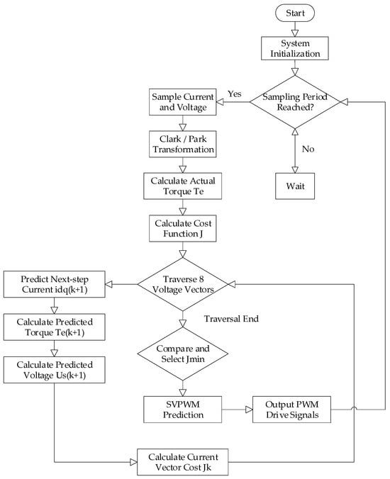
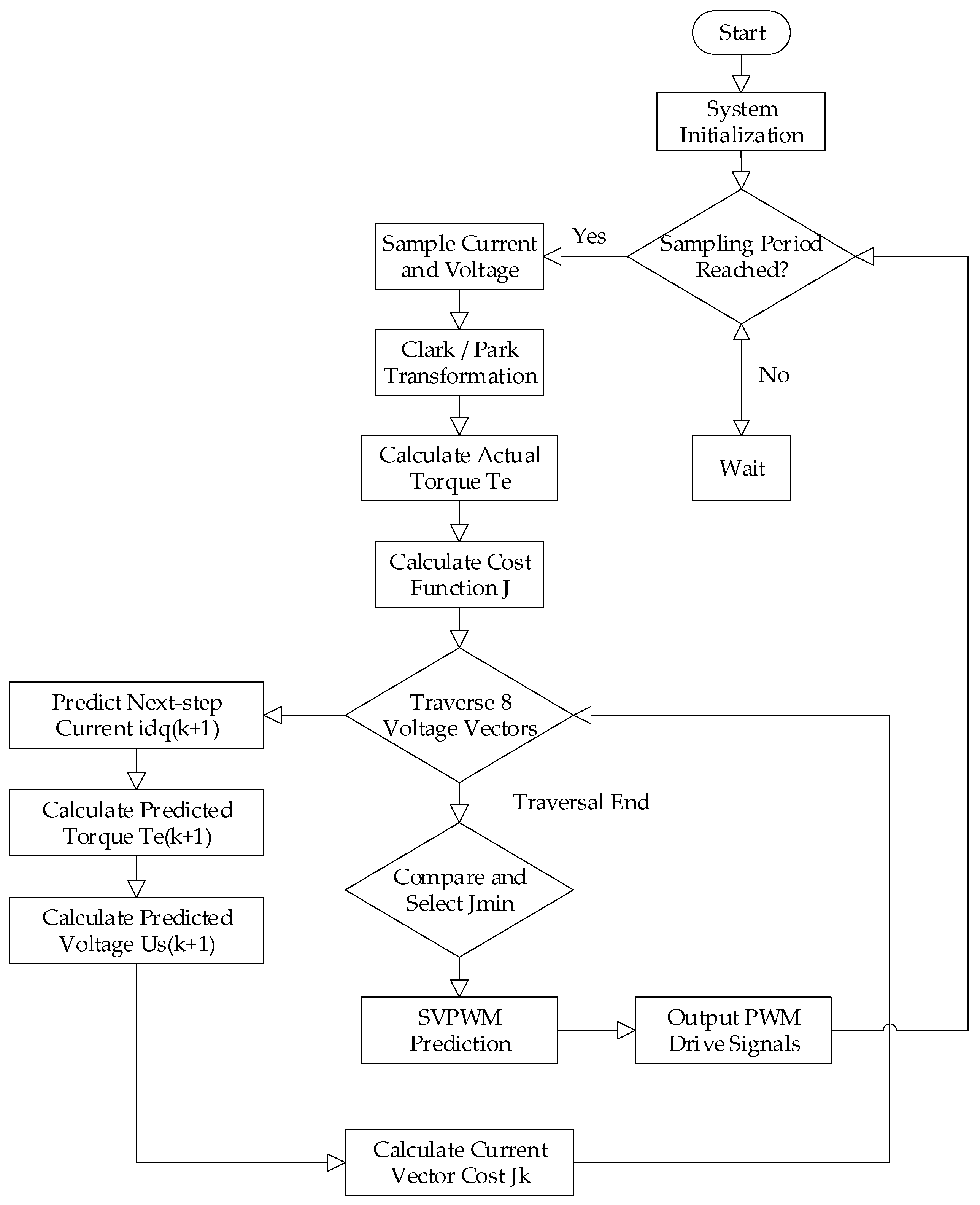
The execution flow of three-vector model predictive current control (TV-MPCC) within each control cycle follows the logical sequence shown in Figure 1. From a finite candidate set, the core idea is to find a combination of three voltage vectors along with their optimal dwell times that minimizes the current tracking error.
Figure 1.
Execution flow of TV-MPCC within each control cycle.
The TV-MPCC framework adopted here follows the three-vector prediction and cost function optimization approach established in [38].
A three-phase two-level inverter can output eight basic voltage vectors, including six non-zero active vectors (V1–V6) and two zero vectors (V0, V7), whose distribution in the complex plane divides the space into six sectors. The candidate vector combinations of traditional TV-MPCC do not enumerate all possibilities but are based on the sector in which the reference voltage vector resides. Each candidate combination to be evaluated comprises one primary active vector Vm (e.g., one of the two basic vectors of that sector), one auxiliary active vector Va (typically adjacent to Vm), and one zero vector V0.
For each candidate vector combination {Vm, Va, V0}, a set of optimal dwell times ti, tj, and tz (satisfying ti + tj + tz = 1) is computed by solving a constrained optimization problem. The average voltage vector can be synthesized by these three vectors over their dwell times as:
where udi, uqi, udj, and uqj are the d- and q-axis voltage components of ud and uj.
This average voltage vector constitutes the control action that may be applied to the motor.
To evaluate the merit of each candidate vector combination, it is necessary to predict the current response at the next instant after applying this synthesized voltage. This prediction is based on the discretized d–q axis motor model established in Section 2. The synthesized voltage vector is substituted into the following prediction equation:
where id(k) and id(k + 1) are the d-axis currents at instants k and k + 1, respectively; iq(k) and iq(k + 1) are the q-axis currents at instants k and k + 1, respectively; ud(k) and uq(k) are the d- and q-axis voltages at instant k; and ωe(k) is the electrical angular velocity of the rotor at instant k.
A cost function is constructed to quantify the tracking performance of each candidate vector combination. The cost function is typically defined as the weighted sum of the d- and q-axis current tracking errors:
where id* and iq* are the current reference values, and λ is a weighting factor. The algorithm traverses all pre-defined candidate vector combinations and executes the above steps for each one. Finally, the vector combination that minimizes the cost function g, along with its corresponding optimal duty cycles, is selected and applied to the motor via the inverter in the next control cycle.
4. Design of Three-Vector Model Predictive Current Control Based on Improved Sliding Mode Observer
This section aims to resolve the parameter sensitivity issues of TV-MPCC revealed in Section 2. The core idea is to use a sliding mode observer based on a novel dual power-rate reaching law to estimate and compensate in real time the equivalent disturbances generated in the system by parameter mismatch, thereby constructing an enhanced predictive current controller that is insensitive to parameter variations.
4.1. Design of the Sliding Mode Observer
4.1.1. Observer Structure Design
Based on the PMSM model in the two-phase stationary reference frame from Section 2, a current sliding mode observer is constructed. The dynamic equations of the observer are as follows:
where îα and îβ are the stator currents estimated by the observer; and are the nominal parameters set in the controller; and zα and zβ are the sliding mode control output terms to be designed. As indicated by Equation (7), the core performance of the sliding mode observer depends on the design of the sliding mode control term z. The term z must be capable of driving the current estimation error to converge rapidly and smoothly to zero, while maintaining strong robustness against external disturbances and parameter mismatch. To this end, this paper designs a novel dual power-rate reaching law to precisely construct z.
4.1.2. Application of the Novel Dual Power-Rate Reaching Law
For the definition of the sliding variable, s is defined as the current estimation error, s = iα_hat − iα (and similarly s = iβ_hat − iβ for the beta axis), which represents the deviation of the observed current from the measured current. Following dimensional analysis of Equation (8), the unit of s is [A]; ds/dt has the unit [A/s]; k1|s|α has the unit [A (1−α)/s] when alpha is in (0,1), matching ds/dt; k2|s|β * s has the unit [A β/s]; and k3*tanh(μ*s) has the same unit as k3, with mu having the unit [1/A] to make the argument of tanh dimensionless.
To generate the sliding mode control term z satisfying the above requirements, this paper conducts rigorous mathematical derivation based on the designed novel dual power-rate reaching law.
where 0 < α < 1 and 1 < β < 2; k1, k2, and μ are all positive constants; sign(·) is the sign function; and tanh(·) is the hyperbolic tangent function.
As shown in the above equation, the reaching law design comprises three terms that collaborate to achieve superior dynamic performance: a power-rate term −k1|s|αsign(s) is introduced to form a terminal attractor, so that even in the vicinity of the sliding surface—i.e., when |s| is small—a relatively large approaching force is still maintained to accelerate convergence; a nonlinear term −k2|s|βs is introduced with a power exponent between linear and quadratic, providing faster convergence speed than the traditional exponential reaching law when the system state is far from the sliding surface—i.e., when |s| is large; and a hyperbolic tangent function term −k3tanh(μs) is introduced to eliminate chattering.
The operating principle of this reaching law can be divided into two phases according to the distance between the system state and the sliding surface. When the system state is far from the sliding surface, the power-rate term −k1|s|αsign(s) and the nonlinear term −k2|s|βs jointly dominate the approaching process; because 0 < α < 1 and 1 < β < 2, the system approaching speed during this phase is much faster than that of the traditional exponential reaching law, enabling a rapid dynamic response. When the system state is close to the sliding surface, the terminal attractor term −k3tanh(μs), due to its slower decay characteristics, becomes the key to guaranteeing asymptotic convergence. Meanwhile, the role of the hyperbolic tangent function term −k3tanh(μs) becomes prominent; this function is a smooth and continuous approximation of the sign function, and as s approaches zero, its output also smoothly approaches zero, thereby causing the switching control force of the system to vary continuously, fundamentally avoiding the chattering problem caused by the sign function and significantly improving steady-state accuracy and control smoothness.
First, differentiating the sliding surface yields:
Substituting Equations (1) and (7) into Equation (9) yields an alternative expression:
where D is the lumped disturbance term, encompassing the combined effects of parameter mismatch and back-EMF.
Setting Equation (10) equal to Equation (8) yields:
From this equation, the theoretical expression for the sliding mode control output z can be solved:
Provided that the gain k3 is sufficiently large, the following equivalent control law can be adopted for implementation:
At this point, by combining the novel reaching law with the observer structure, the final implementation formula for the sliding mode control term is obtained. This formula will be directly used to update the observer dynamics, thereby forming a complete and high-performance sliding mode observer.
Parameter Tuning Guideline: The proposed reaching law involves five tunable parameters. The following heuristic procedure is recommended: (1) α (0 < α < 1) controls convergence speed near the sliding surface; smaller alpha gives stronger terminal attraction. A value of 0.5 is recommended as a starting point. (2) β (1 < β < 2) governs convergence when far from the surface; larger beta accelerates approach. A value of 1.25 is recommended. (3) k1 and k2 are positive gains; increasing k1 improves near-surface convergence while increasing k2 speeds up far-field approach. Both should be increased gradually until satisfactory dynamic response is achieved without excessive overshoot. (4) μ is the slope parameter of tanh(μs); larger mu makes tanh approximate sign more closely, trading smoothness for chattering. μ = 6 was found to balance these in the present system. (5) k3 must satisfy k3 > Dmax as discussed in the disturbance bound remark below; since |tanh(μs)| ≤ 1, the maximum switching force is k3, which must exceed the worst-case disturbance.
4.1.3. Stability Proof
To further verify the stability of the observer, the following Lyapunov function is selected:
Differentiating V yields:
Substituting the novel reaching law gives:
Since 0 < α < 1 and 1 < β < 2, with k1, k2, k3, and μ all being positive constants, for the case s > 0, we have sign(s) > 0 and tanh(μs) > 0. Each term in the reaching law contributes a negative component to ds/dt: the terminal attractor −k1|s|α sign(s) < 0; the power-rate term −k2|s|β < 0; and the tangent hyperbolic term −k3 tanh(μs) < 0. Therefore, ds/dt < 0 and dV/dt = s · ds/dt < 0. For the case s < 0, sign(s) < 0 and tanh(μs) < 0. The terminal attractor term −k1|s|α sign(s) = k1|s|α > 0, driving s toward zero from the negative side. The tangent hyperbolic term −k3 tanh(μs) = k3|tanh(μs)| > 0, providing additional convergence force. The power-rate term −k2|s|β is negative when s < 0, acting as a deceleration term that limits the overshooting speed. Since for |s| < 1 we have |s|α > |s|β, k1|s|α dominates k2|s|β near the sliding surface. Combined with the disturbance bound |D| ≤ Dmax and the condition k3 > Dmax, the net convergence force remains positive, ensuring dV/dt < 0 holds for both s > 0 and s < 0. Based on Lyapunov stability theory, the observer is therefore asymptotically stable.
Regarding the disturbance bound, the lumped disturbance D in Equation (10) satisfies |D| ≤ Dmax, where Dmax is determined by the maximum parameter mismatch and the rated back-EMF. The observer gain k3 should be selected such that k3 > Dmax to ensure that the tanh-based switching term −k3 tanh(μs) can overcome the disturbance and maintain the sliding mode. Since |tanh(μs)| ≤ 1, the maximum switching force provided by this term is k3; therefore, k3 > Dmax guarantees that the convergence-driving component always exceeds the worst-case disturbance. In practical implementation, Dmax can be estimated from the worst-case parameter deviation (e.g., 50% resistance mismatch) and the maximum back-EMF at rated speed.
4.2. Back-EMF Extraction and Feedforward Compensation Mechanism
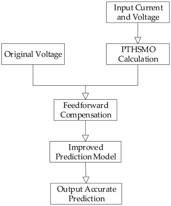
The core task of this section is to transform the output of the sliding mode observer into actual corrections to the prediction model of TV-MPCC. The overall flow is illustrated in Figure 2.
Figure 2.
Overall flow of back-EMF extraction and feedforward compensation.
4.2.1. Extraction of the Equivalent Back-EMF
When the sliding mode observer enters the steady state—that is, when the current estimation error and its derivative both approach zero—the system enters the so-called ‘sliding mode motion.’ At this point, the dynamic average value of the sliding mode control term in the observer is exactly balanced by the lumped disturbance in the system.
On the sliding surface, Equation (10) can be simplified to:
The lumped disturbance D encompasses the combined effect of parameter mismatch and the true back-EMF. Therefore, the equivalent value of the sliding mode control quantity directly reflects the total disturbance of the system. Accordingly, the equivalent back-EMF can be estimated as:
Since the designed reaching law directly uses the smooth tanh function output as z, the estimated back-EMF is inherently a continuous and smooth signal. There is no need for the complex low-pass filter and phase compensation typically required by traditional SMOs, greatly simplifying the implementation and ensuring estimation accuracy.
4.2.2. Improved TV-MPCC Prediction Model
The performance bottleneck of traditional TV-MPCC lies in the fact that its prediction model relies on fixed and potentially erroneous nominal parameters. The feedforward compensation mechanism proposed in this section aims to dynamically correct this deficiency.
The fundamental idea behind compensation is to use the estimated equivalent back-EMF as a feedforward term to remove the disturbance voltage from the control voltage.
Equation (5) is modified to the following form:
Without compensation, parameter mismatch (e.g., Rs0 < Rs) causes the model-predicted current ip to exceed the actual current. The controller will output an excessively small voltage based on this over-optimistic prediction, thereby generating a steady-state error.
With compensation, the estimated ê is a positive disturbance voltage. Executing the operation u − ê is equivalent to pre-canceling this additional voltage drop. Therefore, even if the model parameters are incorrect, the prediction model can output a predicted current ip(k + 1) that is closer to the true system dynamics.
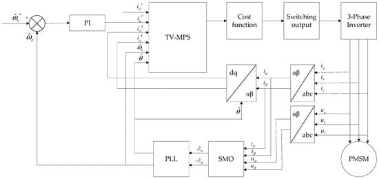
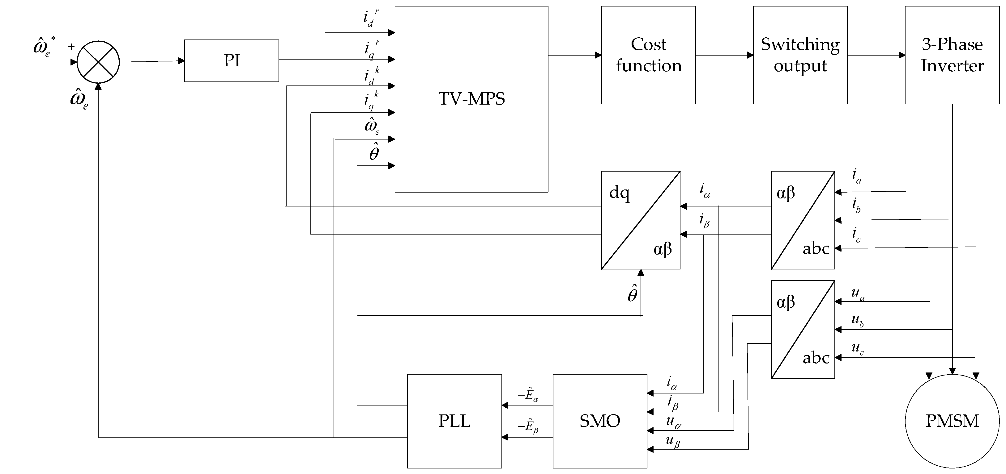
The overall control structure of the system is shown in Figure 3. The system converts these voltage commands into three-phase AC signals to drive the PMSM through model prediction, SVPWM, and a three-phase inverter, thereby achieving the conversion of electrical energy to mechanical energy. The three-phase currents are sampled and transformed into the αβ coordinate system and then fed back to the model predictor via the dq/αβ transformation for inner-loop current regulation. Meanwhile, the current signals iα and iβ and voltage signals uα and uβ are fed into the new sliding mode observer (PTHSMO) to estimate the rotor position and motor speed. The estimated motor speed is further fed back to the model predictive controller to realize sensorless closed-loop FOC, thereby ensuring dynamic response and control accuracy. The parameters of the sliding mode observer are set as α = 0.5, β = 1.25, and μ = 6. The value of K is selected according to the overall dynamic characteristics and control requirements of the system. represents the given rotational speed.
Figure 3.
Overall control structure of the system.
5. Verification and Result Analysis
To verify the effectiveness of the novel sliding mode observer back-EMF compensation TV-MPCC strategy proposed in this paper, the traditional SMO-compensated TV-MPCC and the novel SMO back-EMF compensated TV-MPCC are presented. In the experiments, both control strategies employ a switching frequency of 10 kHz; the PI regulator parameters for speed control are identical, and the PMSM parameters are listed in Table 1. The experimental results are shown in the following figures.
Table 1.
Permanent magnet synchronous motor parameters.
To ensure safety, a simulation platform was established on the physical basis of the PMSM test system. There has been extensive research on motion control of PMSM servo systems, particularly based on the field-oriented control (FOC) strategy. The FOC method includes the Clarke transformation and Park transformation, space vector pulse-width modulation (SVPWM), a three-phase inverter, and a proportional–integral controller, which is a traditional and widely applied approach.
The 100 W PMSM was selected because: (1) it matches the power rating of automotive electronic water pump motors, which is the target application for the proposed control strategy; and (2) a 100 W motor enables safer and more convenient laboratory testing while exhibiting the same control challenges (parameter sensitivity, chattering) as higher-power machines at the algorithm level. The SP1000 rapid prototyping controller was selected for its dual core DSP + FPGA architecture that supports the required 10 kHz switching frequency and real-time code generation. Regarding measurement uncertainty: the current sensors have a measurement accuracy of plus–minus 0.5% full scale, and the speed is estimated from the observer (no mechanical encoder is used), with the true speed reference used only for PI controller input comparison.
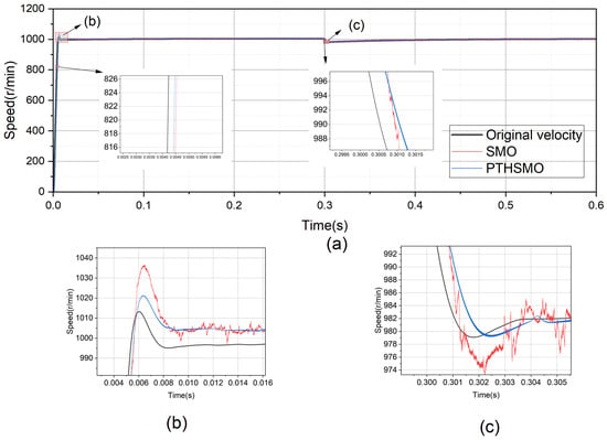
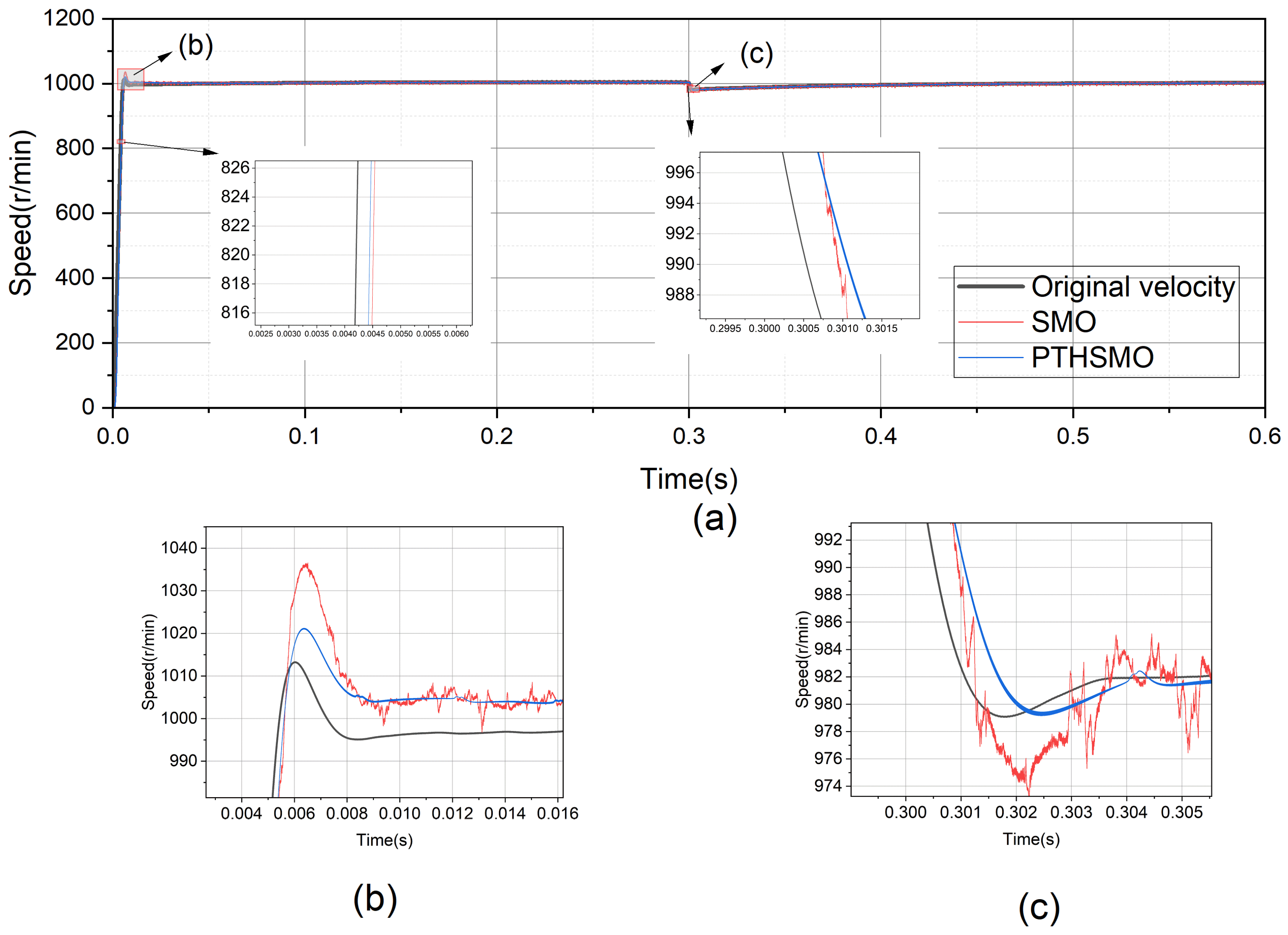
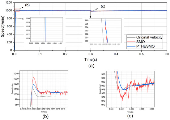
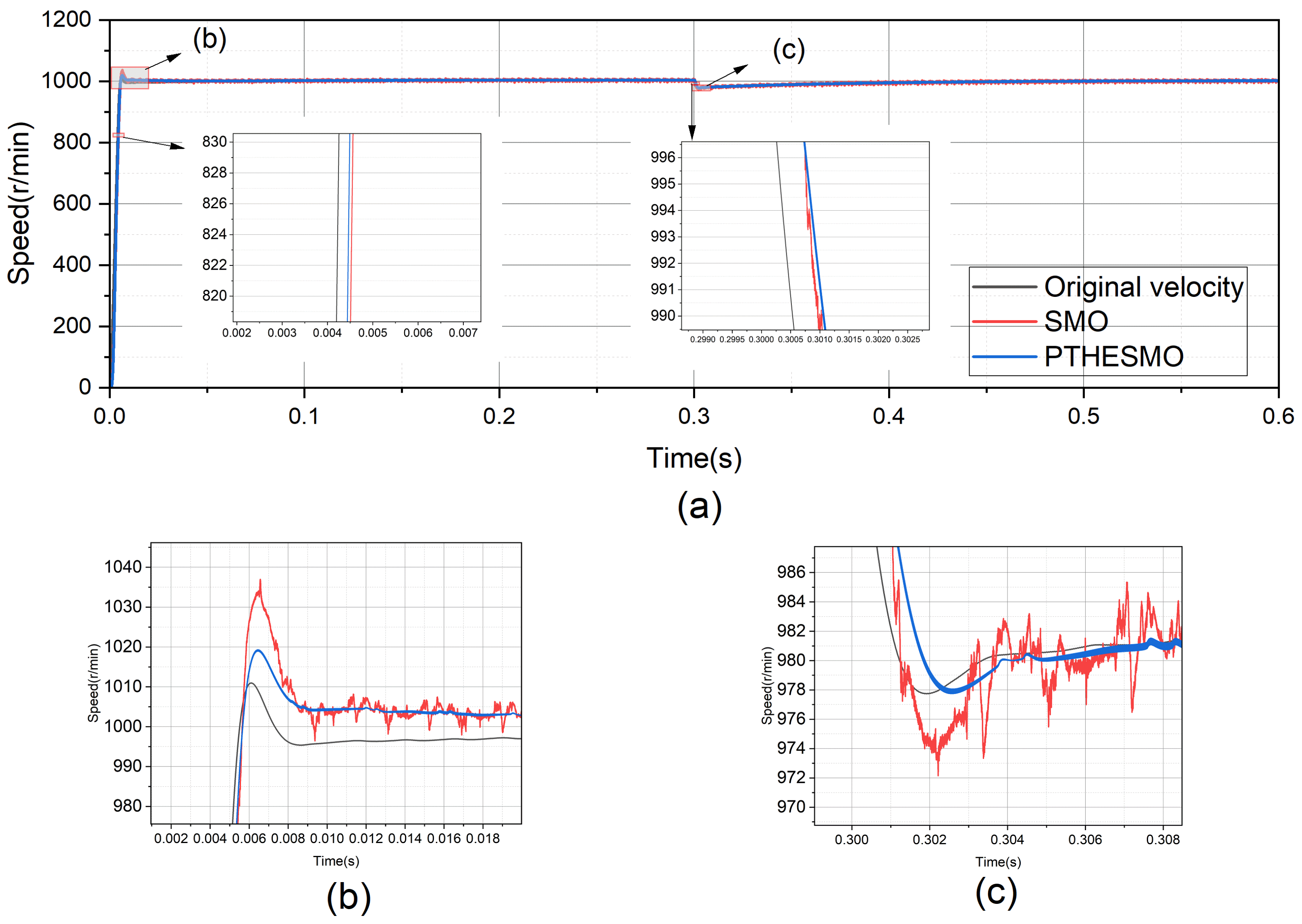
To facilitate reading, the control strategies compared throughout the results Section 5 are defined here: original velocity denotes TV-MPCC without any observer-based compensation, serving as the baseline reference; SMO denotes the traditional sliding mode observer-based TV-MPCC with a standard sign-function reaching law; PTHSMO denotes the proposed dual power-rate hyperbolic tangent SMO-based TV-MPCC (observer only, without back-EMF feedforward compensation), used for speed stability comparison (Figure 4, Figure 5, Figure 6 and Figure 7); and PTHESMO denotes the complete proposed strategy, i.e., PTHSMO with back-EMF feedforward compensation (as described in Section 4.2), used for three-phase current, rotor position, and experimental comparisons (Figure 8, Figure 9, Figure 10 and Figure 11).
Figure 4.
Speed curves of the actual rotational speed and two control strategies at a reference speed of 1000 r/min. (a) Overall startup and load-application curves of actual and estimated speeds at 1000 r/min. (b) Enlarged startup curves at 1000 r/min. (c) Enlarged speed curves under load application at 1000 r/min.
Figure 5.
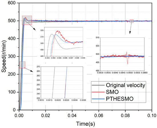
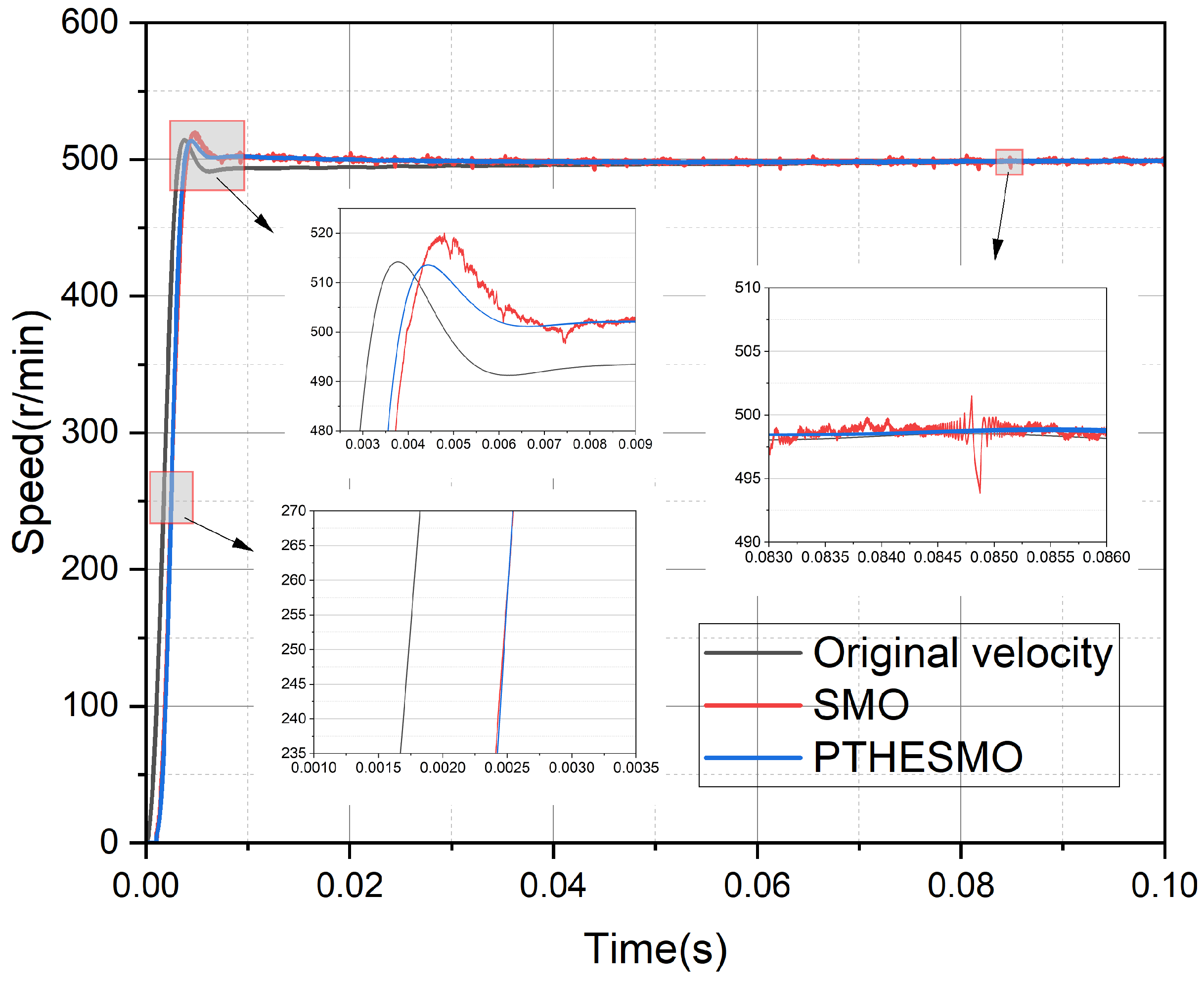
Actual and estimated speed startup curves of two control strategies at a reference speed of 500 r/min.
Figure 6.
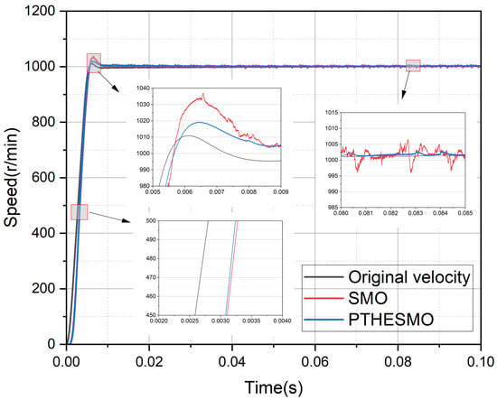
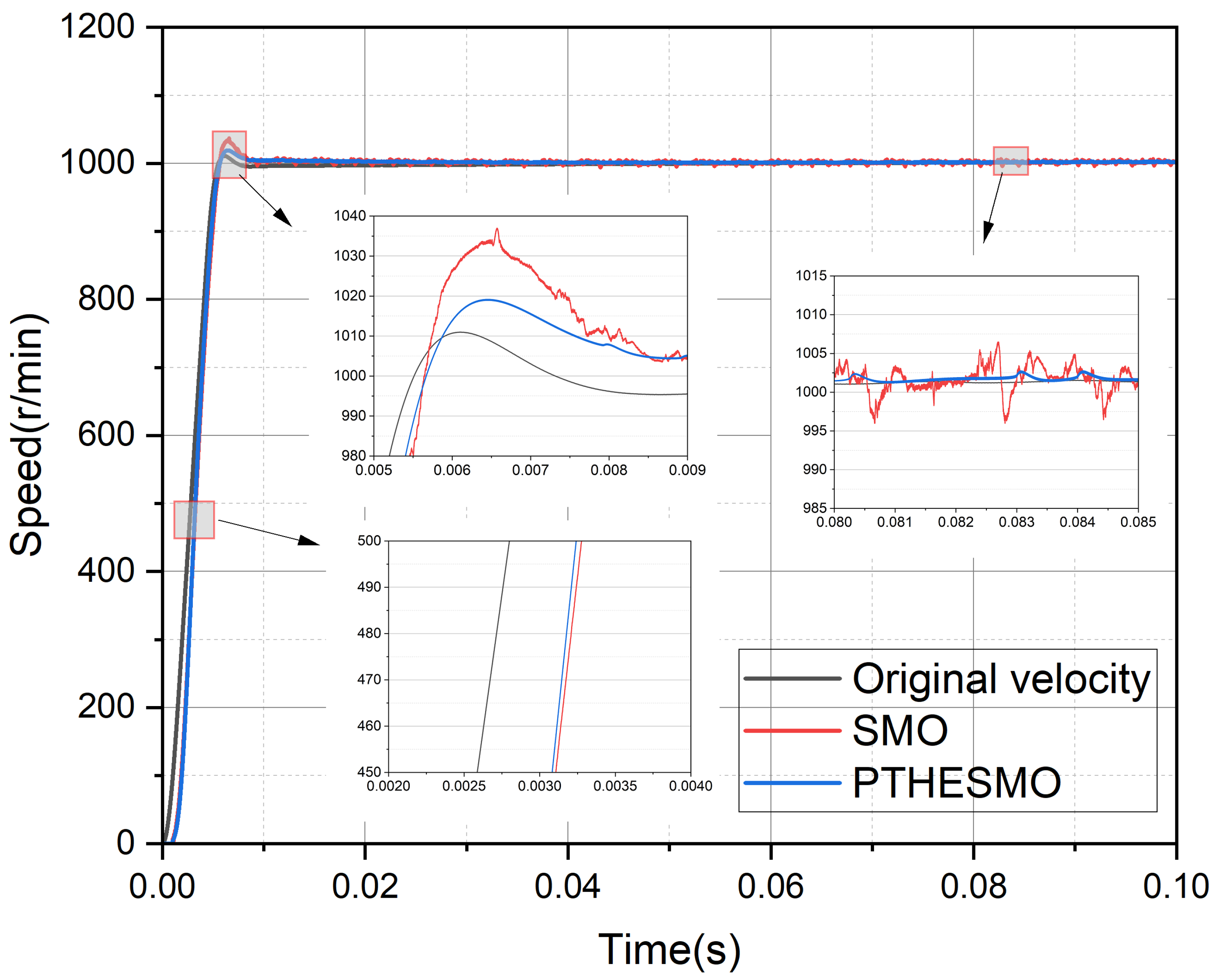
Actual and estimated speed startup curves of two control strategies at a reference speed of 1000 r/min.
Figure 7.
Speed curves of the actual rotational speed and two control strategies at a reference speed of 1000 r/min. (a) Overall startup and load-application curves. (b) Enlarged startup curves. (c) Enlarged curves under load application.
Figure 8.
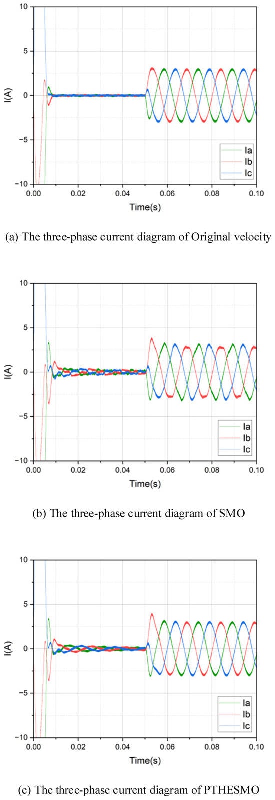
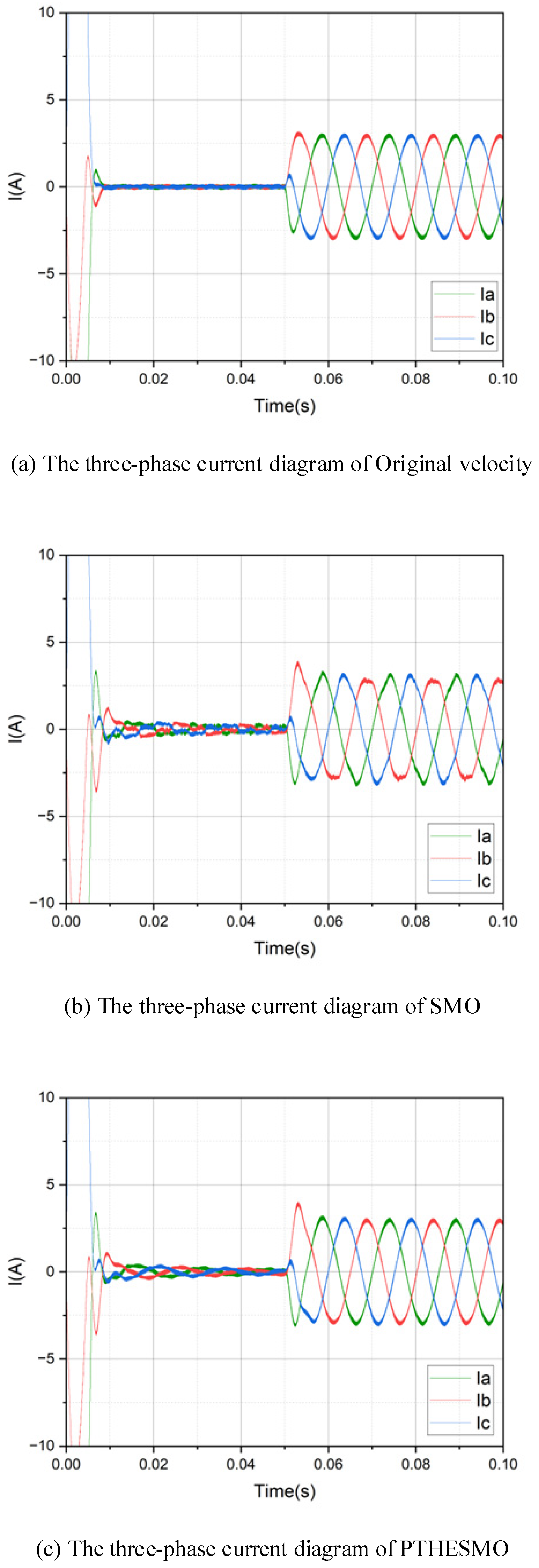
Three-phase current diagrams of three control strategies. (a) Three-phase currents of original velocity. (b) Three-phase currents of SMO. (c) Three-phase currents of PTHESMO.
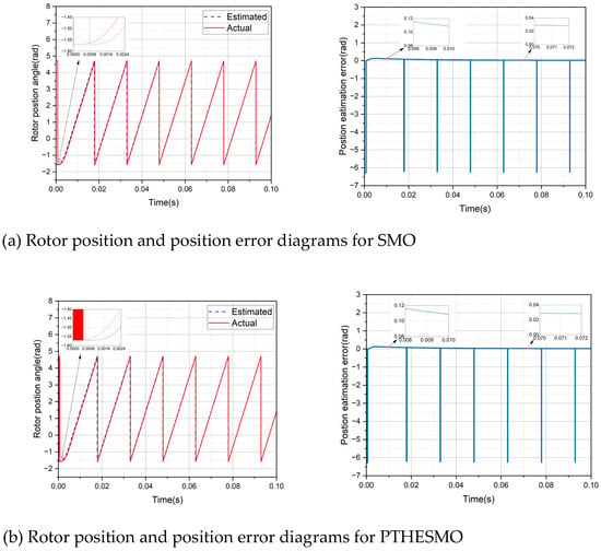
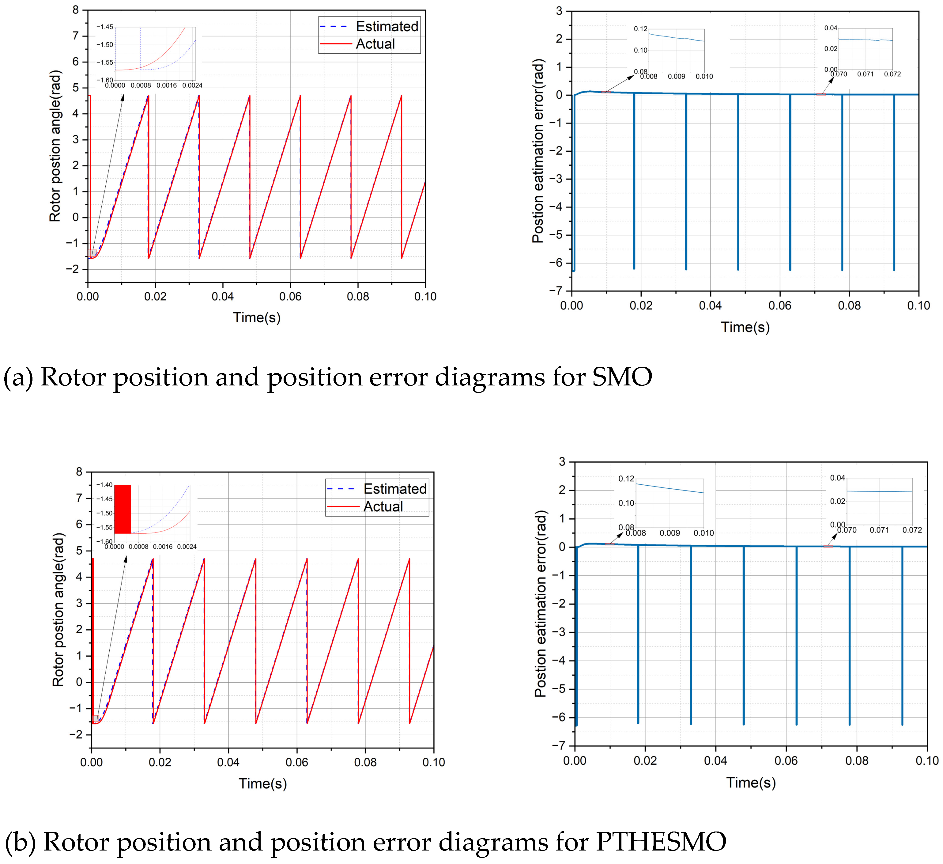
Figure 9.
Rotor position and position error diagrams for SMO and PTHESMO. (a) Rotor position and position error diagrams for SMO. (b) Rotor position and position error diagrams for PTHESMO.
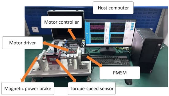
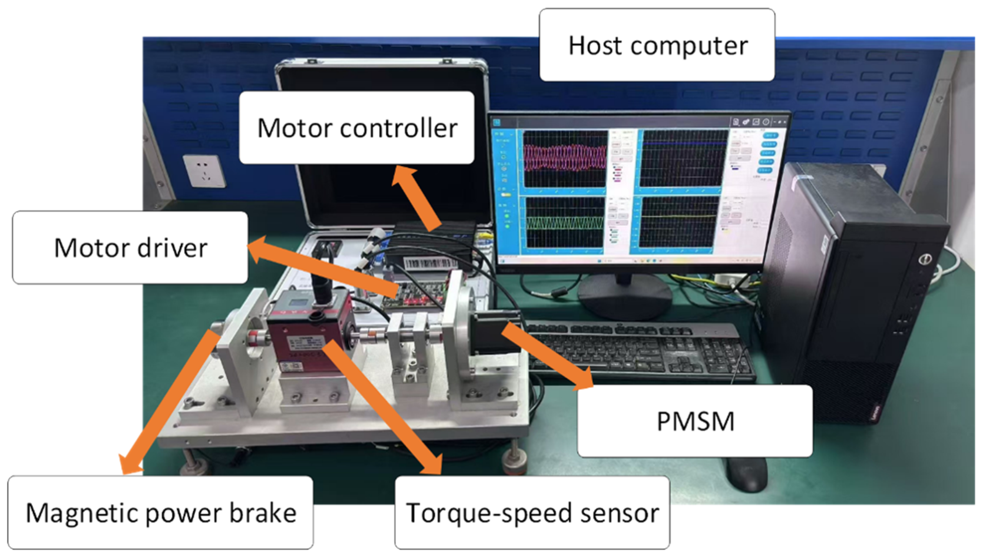
Figure 10.
PMSM drive experimental platform.
Figure 11.
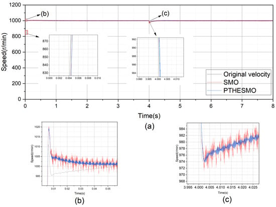
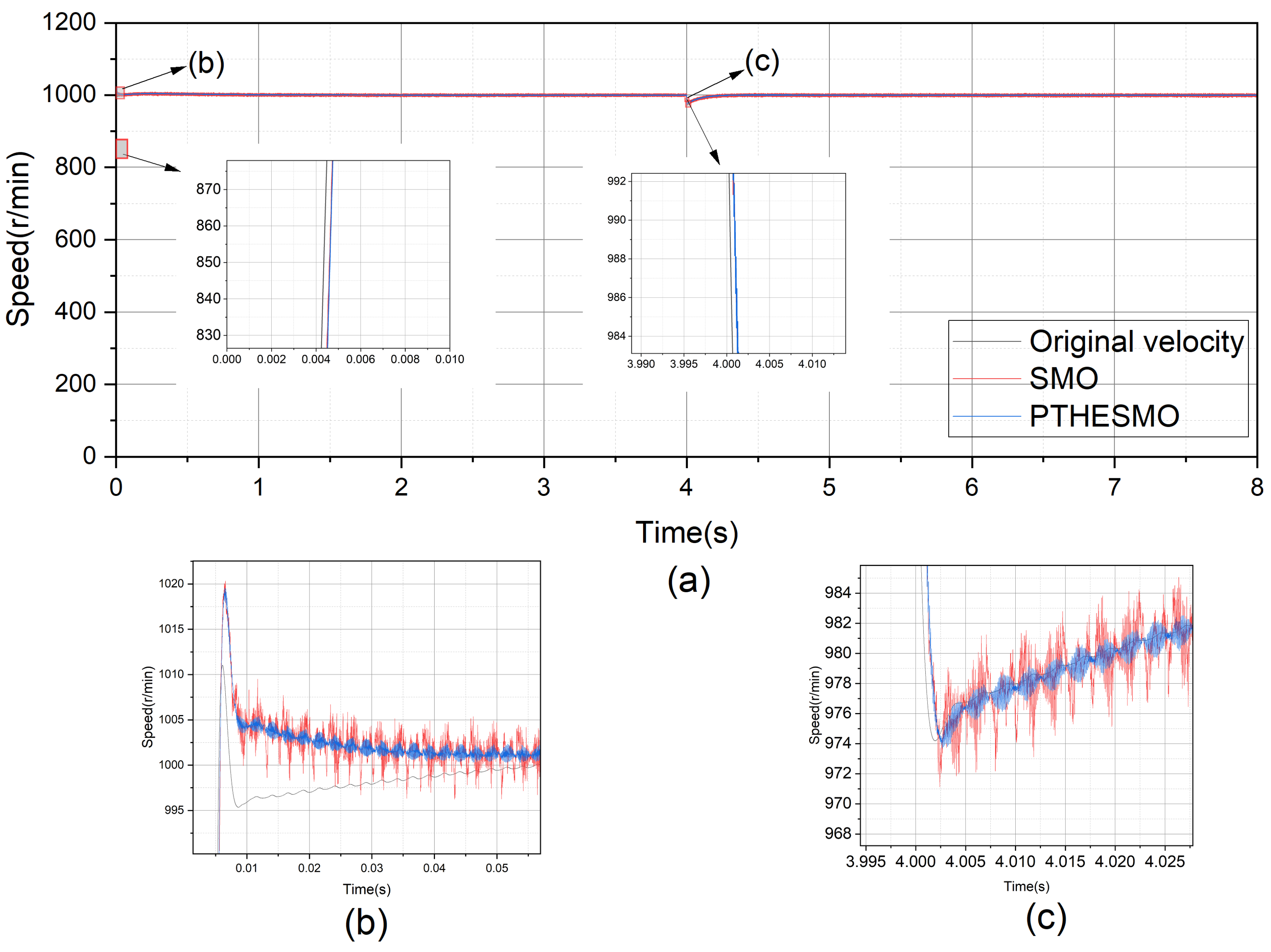
Speed curves of the actual rotational speed and two control strategies at a reference speed of 1000 r/min. (a) Overall startup and load-application curves of actual and estimated speeds at 1000 r/min. (b) Enlarged startup curves at 1000 r/min. (c) Enlarged speed curves under load application at 1000 r/min.
Startup and load speed simulation experiments. The simulation experiments first evaluated the no-load startup response performance of the two control strategies (SMO and PTHSMO) at a reference speed of 1000 r/min. When the motor reached 1000 r/min, as shown in Figure 4b, the overshoot values of SMO and PTHSMO were 37.23 r/min and 19.90 r/min, respectively, while the settling times were 7.3 ms and 6 ms. When the motor operated stably at 1000 r/min, an external load torque of 0.3 Nm was applied at t = 0.3 s to evaluate the load response performance. As shown in Figure 4c, the speed drops of SMO and PTHSMO were 49.81 r/min and 35.71 r/min, respectively, with corresponding regulation times of 2 ms and 1.5 ms. Comparative analysis indicates that in PTHSMO, the synergistic fast convergence of k1|s|α and k2|s|β enables the system to exhibit better overshoot suppression and shortened settling time during no-load startup. Furthermore, under load disturbances, this method achieves a smaller speed drop and faster recovery, thereby ensuring superior dynamic response and stability.
The results indicate that the k1|s|α term in PTHSMO effectively suppresses system oscillations, thereby further enhancing control performance.
The simulation experiments further evaluated the no-load startup response performance of the SMO and PTHSMO control strategies at reference speeds of 500 r/min and 1000 r/min. When the motor reached 500 r/min, as shown in Figure 5, the overshoot values of SMO and PTHSMO were 20.15 r/min and 13.04 r/min, respectively, while the settling times were 5.2 ms and 4.8 ms. When the motor operated stably at 1000 r/min, as shown in Figure 6, the overshoot values of SMO and PTHSMO were 37 r/min and 19 r/min, respectively, while the settling times were 7.25 ms and 5.3 ms.
Subsequently, the load response performance was evaluated by applying an external load torque of 0.3 Nm at t = 0.3 s while the motor operated stably at 1000 r/min. As shown in Figure 7c, the speed drops of SMO and PTHSMO were 31.74 r/min and 26.10 r/min, respectively, with corresponding regulation times of 20.3 ms and 5.2 ms. Comparative analysis shows that in PTHSMO, the synergistic fast convergence of the novel reaching law and the feedforward compensation mechanism enables better overshoot suppression and shortened settling time during no-load startup. Furthermore, under load disturbances, this method achieves a smaller speed drop and faster recovery, thereby ensuring superior dynamic response and stability.
Motor current simulation experiment. At a reference speed of 1000 r/min, the three-phase current waveforms of the proposed PTHESMO-based TV-MPCC were compared with those of the traditional SMO-based TV-MPCC and a baseline TV-MPCC without any observer compensation (i.e., using the original velocity directly). As shown in Figure 8, the PMSM actual speed and three-phase current waveforms under the three cases clearly reflect the current variations during motor startup and load changes. At the initial startup stage, due to the large starting friction and rotor moment of inertia, the three-phase currents exhibit transient oscillations and rise rapidly to provide sufficient torque to drive the rotor. As the motor continues to operate, the current quickly stabilizes. When a sudden load of 0.3 Nm is applied at t = 0.03 s, the abrupt change in load causes a momentary electromagnetic torque imbalance, leading to a rapid response in three-phase currents accompanied by brief oscillations; thereafter, the current reaches a stable value and remains constant. As shown in Figure 8a–c, compared with the baseline without observer compensation and the traditional SMO, the three-phase currents under PTHESMO exhibit smaller oscillations and better waveform tracking during startup and sudden load application, with the obtained current waveforms being closer to ideal AC signals.
Rotor position simulation experiment. In this experiment, the rotor position and position error under two control strategies were tested at a reference speed of 1000 r/min, as shown in Figure 9a,b. During no-load motor startup, PTHESMO shows higher conformity with the actual rotor position compared with SMO. The rotor position errors of SMO and PTHESMO are 0.1358 rad and 0.1266 rad, respectively; the high-frequency discontinuous switching function in SMO further aggravates chattering in the position error. In summary, by comparing the simulation results of SMO and PTHESMO control strategies in terms of speed, current, and rotor position under motor startup and sudden load conditions, PTHESMO demonstrates clear advantages. Specifically, PTHESMO not only exhibits faster convergence and a smaller amplitude range but also demonstrates stronger overshoot suppression and disturbance rejection capability. Furthermore, it performs better in speed and position tracking accuracy. These characteristics collectively demonstrate the effectiveness of PTHESMO in motor control.
The reduced chattering in PTHESMO is directly attributable to the tanh(μs) replacing sign(s) in the reaching law; as analyzed in Section 4.2.1, the tanh function is Lipschitz continuous and its output smoothly vanishes as the sliding variable s approaches zero, thereby eliminating the discontinuous switching force that causes high-frequency oscillation in the conventional SMO. This is consistent with the visibly smoother position error waveform of PTHESMO in Figure 9b compared to that of SMO in Figure 9a.
To verify the effectiveness of the proposed strategy, this paper establishes a PMSM drive experimental platform, as shown in Figure 10. The core of this platform is the SP1000 rapid prototyping controller, which adopts a dual core architecture with cooperative processing by a DSP and an FPGA, paired with a motor drive test box and an integrated motor test bench, constituting a fully functional and highly reliable hardware-in-the-loop simulation test system. The control algorithm is developed based on model-based design and is downloaded to the controller via automatic code generation technology. Combined with host computer software, real-time data monitoring and online parameter tuning are realized via Ethernet.
For motor startup and load speed experimentation, in the experimental verification stage, the no-load startup responses of two control strategies (SMO and PTHESMO) at a reference speed of 1000 r/min were tested. When the motor speed reached 1000 r/min, as shown in Figure 11, the overshoot values of SMO and PTHESMO were 20.34 r/min and 19.55 r/min, respectively, while the settling times were 57.6 ms and 57 ms. Furthermore, when the motor operated stably at 1000 r/min, a load torque of 0.3 Nm was applied at t = 4 s to evaluate the load response performance. At this point, the speed drops of SMO and PTHESMO were 29.07 r/min and 26.30 r/min, respectively, with corresponding regulation times of 46.2 ms and 24.5 ms.
In summary, through combined experimental and simulation validation, the PTHESMO exhibits fast adaptability, small amplitude fluctuations, effective overshoot control, strong disturbance rejection, and high-precision position tracking capability. These characteristics highlight the effectiveness and feasibility of the PTHESMO control strategy.
6. Conclusions
The PTHESMO control strategy proposed in this paper achieves a synergistic optimization of control performance, computational efficiency, and robustness in the PMSM joint drive system. Experimental results demonstrate that, compared with the traditional SMO, the proposed strategy significantly enhances dynamic response quality while maintaining steady-state speed accuracy (ripple < ±5 r/min), where, under a sudden 0.3 Nm load disturbance, the speed recovery time is reduced from 46.2 ms to 24.5 ms, and the speed drop depth is reduced by approximately 10%; during step-up speed transients, the overshoot is reduced by approximately 5%. What is particularly noteworthy is the fact that the equivalent back-EMF feedback mechanism significantly reduces speed fluctuations, contributing to the suppression of electromagnetic interference (EMI). In addition, the improved observer effectively suppresses the initial peak value and high-frequency noise, enabling high-accuracy disturbance estimation and feedforward compensation even under actual operating conditions involving static friction and parameter perturbations. Regarding computational burden, when compared with the conventional SMO, the PTHSMO requires only three additional multiply–accumulate operations per control cycle (for the two power-rate terms and the tanh term), resulting in negligible additional execution time that is well within the real-time capability of standard embedded DSP controllers. The present study validates the strategy under medium-speed operation (500–1000 r/min) using a 100 W PMSM. Future work will extend experimental validation to very low-speed conditions (where back-EMF is small) and to higher-power machines to further assess generalizability of the proposed method.
Regarding generalizability, the proposed PTHSMO framework is applicable to any surface-mounted PMSM drive system where parameter mismatch and back-EMF disturbances are the primary sources of model uncertainty. The TV-MPCC structure is independent of motor power rating; the key parameter that affects generalizability is the disturbance bound Dmax, which determines the required observer gain k3 (k3 > Dmax). For machines with different rated back-EMF or significantly different parameter sensitivities, the gains k1, k2, and k3 should be retuned following the guidelines provided in Section 4.1.2.
These results demonstrate that the proposed method effectively mitigates the chattering phenomenon of traditional sliding mode observers in PMSMs without significantly sacrificing control performance, providing a feasible pathway for high-performance servo control in resource-constrained scenarios. Future work will focus on the stable operation of PMSMs under parameter variations and external disturbances, as well as the extension of the strategy’s generalization capability under sensorless conditions.
Author Contributions
Conceptualization, H.Z. and X.M.; Methodology, H.Z.; Software, H.Z. and J.M.; Validation, H.Z., Z.X. and J.M.; Formal analysis, H.Z. and Z.X.; Investigation, Z.X., J.M. and Y.G.; Resources, P.F.; Data curation, Z.X. and Y.G.; Writing—original draft preparation, H.Z.; Writing—review and editing, X.M., P.F. and Y.G.; Visualization, J.M.; Supervision, X.M. and P.F.; Project administration, X.M. and P.F.; Funding acquisition, X.M. All authors have read and agreed to the published version of the manuscript.
Funding
This research was funded by 2025 Songjiang District Science and Technology Key Project, grant number 2025SJJBGS3. The APC was funded by Shanghai University of Engineering Science.
Data Availability Statement
The original contributions presented in this study are included in the article. Further inquiries can be directed to the corresponding author.
Conflicts of Interest
J.M. and Y.G. are employees of Shanghai Kehai-Huatai Marine Electric Equipment Corp. The remaining authors declare that the research was conducted in the absence of any commercial or financial relationships that could be construed as potential conflicts of interest.
References
- Pan, Y.; Shen, Y.; Mei, Q. 基于改进等效输入扰动的永磁同步电机跟踪控制 [Tracking Control of Permanent Magnet Synchronous Motor Based on Improved Equivalent Input Disturbance]. J. Wuhan Univ. (Eng. Ed.) 2026. Available online: https://wsdd.cbpt.cnki.net/WKC/WebPublication/index.aspx?mid=wsdd (accessed on 1 May 2026).
- Shan, L.; Liang, Q. 基于改进自适应超螺旋滑模观测器的AGV驱动电机无传感器控制 [Sensorless Control of AGV Drive Motor Based on Improved Adaptive Super-Twisting Sliding Mode Observer]. Electr. Eng. Mater. 2026, 2026, 64–68. [Google Scholar]
- Yu, Y.; Hu, H. Research on PMSM Low Carrier Ratio Sensorless Position Detection Based on Complex-Vector Sliding Mode Observer. Mod. Electron. Technol. 2026, 49, 1–6+13. [Google Scholar]
- Zhou, H.; Gong, J.; Duan, L.; Li, W. Research on Small-Capacitance-Driven PMSM Control for Plant Protection Robots. J. Chin. Agric. Mech. 2026, 47, 112–118. [Google Scholar]
- Dinh, Q.T.; Dinh, T.N.; Quang, D.N.; Van Nam, G. Fixed Time Homogeneous Stability-Based Sliding Mode Control and Disturbance Observer for Surface Mounted Permanent Magnet Synchronous Motors. Control Eng. Pract. 2026, 172, 106895. [Google Scholar] [CrossRef] [Scilit]
- Xie, S.; Wei, Z.; Lv, Y. 基于NFTSM与STRL滑模观测器的永磁同步电机无传感器控制 [Sensorless Control of PMSM Based on NFTSM and STRL Sliding Mode Observer]. Modular Mach. Tool Autom. Manuf. Tech. 2026. Available online: https://zhjc.cbpt.cnki.net/portal (accessed on 1 May 2026).
- Zou, X.; Yang, K. Sensorless Control of Permanent Magnet Synchronous Motor Based on Variable Universe Fuzzy Sliding Mode Observer. Measurement 2026, 271, 120877. [Google Scholar] [CrossRef] [Scilit]
- Wang, G.; Yuan, Y.; Yuan, C.; Wuyun, X. 改进滑模观测器与高频脉振注入的AFPMSM全速域无感控制研究 [Full-Speed-Range Sensorless Control of AFPMSM Based on Improved Sliding Mode Observer and High-Frequency Pulsating Injection]. J. Wuhan Univ. Technol. 2026, 48, 100–107+114. [Google Scholar]
- Huang, S.; Huang, Y.; Wang, L.; Shi, L.; Zhang, J. An Adaptive Full-Order Sliding-Mode Observer Based-Sensorless Control for Permanent Magnet Synchronous Propulsion Motors Drives. Vehicles 2026, 8, 34. [Google Scholar] [CrossRef] [Scilit]
- Dinh, T.N.; Duc, Q.N.; Phuong, V.; Van Nam, G. Speed Up Reaching Law Design of a Novel Disturbance Observer and Sliding Mode Control for Surface Mounted Permanent Magnet Synchronous Motor. Eng. Res. Express 2026, 8, 035311. [Google Scholar] [CrossRef] [Scilit]
- Dou, L.; Xiao, S.; Yang, Z. 永磁同步电机全速域无传感器最优控制策略 [Full-Speed-Range Sensorless Optimal Control Strategy for Permanent Magnet Synchronous Motor]. Mod. Electron. Technol. 2026, 49, 80–86. [Google Scholar]
- Liu, Y. Design of Nonlinear Fault Estimation Sliding Mode Observer for Permanent Magnet Synchronous Motor. Math. Pract. Theory 2026, 56, 111–122. [Google Scholar]
- Cao, B.; Zhang, L. 基于改进滑模观测器的永磁同步电机模型预测电流控制研究 [Research on Model Predictive Current Control of Permanent Magnet Synchronous Motor Based on Improved Sliding Mode Observer]. Mod. Mach. 2025, 2025, 19–25. [Google Scholar]
- Hong, J.; Li, H.; Zhao, M.; Peng, Q.; Huang, E.; Ruan, G. Sliding Mode Control of Permanent Magnet Synchronous Motor with Improved Novel Reaching Law. Modul. Mach. Tool Autom. Manuf. Tech. 2025, 2025, 102–107+112. [Google Scholar]
- Lian, X.; Chen, L. Sliding Mode Control of Permanent Magnet Synchronous Motor Current Sensor with Quasi-PR Regulator. J. Chin. Constr. Mach. 2025, 23, 985–989. [Google Scholar]
- Ren, H.; Song, K.; Xu, X.; Xin, W.; Zhao, Y.; Li, F. 基于模糊控制的永磁同步电机无传感器控制方法 [Sensorless Control Method of Permanent Magnet Synchronous Motor Based on Fuzzy Control]. Electromech. Eng. Technol. 2025, 54, 135–140. [Google Scholar]
- Wang, H.; Zhang, C.; Meng, X. Sensorless Control of PMSM Based on Improved Sliding Mode Observer. Micro-Motors 2025, 53, 42–47. [Google Scholar]
- Wang, B.; Zhang, J.; Jian, W.; Peng, G.; Chen, K. Sensorless Composite Control of Permanent Magnet Synchronous Motor Based on Super-Twisting Sliding Mode Observer. J. Hubei Univ. Automot. Technol. 2025, 39, 45–50. [Google Scholar]
- Sun, C.; Wang, Z.; Wang, C.; Xiao, X.; Gong, S.; Wan, J. Enhanced Sliding-Mode Observer for Mechanical Parameter Estimation and Load Compensation in PMSM Drives. World Electr. Veh. J. 2025, 16, 629. [Google Scholar] [CrossRef] [Scilit]
- Du, Z.; Cheng, Z.; Xu, L.; He, R.; Hu, X. Sensorless Control Method of Permanent Magnet Synchronous Motor Based on Improved Sliding Mode Observer. J. Anhui Univ. Technol. (Nat. Sci. Ed.) 2026, 43, 160–168. [Google Scholar] [CrossRef]
- Mei, J.; Lu, W.; Chen, W.; Yuan, L.; Su, X.; Sun, X. 基于改进滑模观测器的高速永磁同步电机无传感器控制 [Sensorless Control of High-Speed Permanent Magnet Synchronous Motor Based on Improved Sliding Mode Observer]. Electron. Sci. Technol. 2026. [Google Scholar] [CrossRef]
- Zhang, W.; Ding, Z.; Zhu, G. Research on Sensorless Control of PMSM Based on Novel Sliding Mode Observer. Electromech. Eng. Technol. 2026, 55, 16–21. [Google Scholar]
- Li, B.; Zhao, Y.; Gao, A.; Xue, S. Active Disturbance Rejection Control of PMSM with Sliding Mode Observer Based on Improved Exponential Reaching Law. Modul. Mach. Tool Autom. Manuf. Tech. 2025, 2025, 107–111. [Google Scholar]
- Huang, G.; Zhang, Y.; Jia, L.; Li, X.; Zhao, K. A Fault-Tolerant Control Algorithm for Current Sensor Faults in Permanent Magnet Synchronous Motors. Trans. Chin. Electrotech. Soc. 2025, 29, 129–139. [Google Scholar] [CrossRef]
- Ma, S. Control of Permanent Magnet Synchronous Motor Based on Sliding Mode Observer. Mach. Des. Manuf. 2025, 2025, 16–19. [Google Scholar]
- Gao, S.; Liu, K.; Gao, J.; Long, F. Deadbeat Predictive Speed Control of PMSM Based on Improved Super-Twisting Torque Observer. Micromotors 2026. Available online: https://www.zhangqiaokeyan.com/academic-journal-cn_micromotors_thesis/02012166876814.html (accessed on 1 May 2026).
- Bai, W.; Cai, J.; Kuang, Y.; Wang, Y.; Hua, X.; Ma, Z. Research on a Novel Adaptive Sliding Mode Observer Sensorless Control for Dual Three-Phase Permanent Magnet Synchronous Motors. Results Eng. 2025, 27, 105709. [Google Scholar] [CrossRef] [Scilit]
- Huang, Y.; Xie, Y.; Han, W. A Dynamic Self-Adjusting System for Permanent Magnet Synchronous Motors Using an Improved Super-Twisting Sliding Mode Observer. Sensors 2025, 25, 3623. [Google Scholar] [CrossRef] [Scilit] [PubMed]
- Zhao, H.; Ma, X.; Fan, P.; Hu, X. Sensorless Control of Permanent Magnet Synchronous Motor Based on Novel Extended Kalman Filter. J. Electron. Devices 2023, 46, 724–730. [Google Scholar]
- Zhao, H. Research on Control System of Automotive Electronic Water Pump Drive Motor. Master’s Thesis, Shanghai University of Engineering Science, Shanghai, China, 2022. Available online: https://d.wanfangdata.com.cn/thesis/ChhUaGVzaXNOZXdTMjAyNDA5MjAxNTE3MjUSCUQwMzA5MjUwNhoINnc5YmM5NmE%3D (accessed on 1 May 2026).
- He, Z.; Ma, X.; Fan, P.; Zhao, H.; Wang, Y. Research on Sensorless Control Strategy of Permanent Magnet Synchronous Motor. J. Shanghai Univ. Eng. Sci. 2021, 35, 321–326. [Google Scholar]
- He, Z. Research on Sensorless Control Strategy of Automotive Electronic Water Pump. Master’s Thesis, Shanghai University of Engineering Science, Shanghai, China, 2021. Available online: https://kns.cnki.net/kns8s/defaultresult/index?kw=%E6%B1%BD%E8%BD%A6%E7%94%B5%E5%AD%90%E6%B0%B4%E6%B3%B5%E6%B0%B8%E7%A3%81%E5%90%8C%E6%AD%A5%E7%94%B5%E6%9C%BA%E6%97%A0%E4%BC%A0%E6%84%9F%E5%99%A8%E6%8E%A7%E5%88%B6%E7%AD%96%E7%95%A5&dbcode=CDFD (accessed on 1 May 2026).
- Ao, S. Application effect of PMSM current segmented control method based on DM-MPCC algorithm. Sci. Rep. 2025, 15, 35367. [Google Scholar] [CrossRef] [Scilit] [PubMed]
- Van Hoa, D.; Bao Nghia, H.H.; Van Dai, L. Optimizing permanent magnet synchronous motor control: A comparative study of MPCC-based techniques. East.-Eur. J. Enterp. Technol. 2025, 135, 73. [Google Scholar] [CrossRef] [Scilit]
- Li, Y.; Chong, G.; Guo, W.; Xu, Z.; Wang, Z.; Wang, Q.; Gao, S.; Zhang, X.; Tong, R.; Deng, Y. Streamlined control set of MPCC for PMSMs. J. Power Electron. 2025, 26, 67–76. [Google Scholar] [CrossRef] [Scilit]
- Benakcha, M.; Benakcha, A.; Abdessemed, R.; Zouzou, S.E. Sensorless real-time implementation-based FS-MPCC and deadbeat predictive control with delay and dead-time compensation of PMSM using MRAS and T-S fuzzy speed controller. Electr. Eng. 2023, 105, 4139–4156. [Google Scholar] [CrossRef] [Scilit]
- Tang, S.; Wang, Y. An Improved MPCC Method Based on the Predictive Delay Error Analysis for PMSM Speed Control System. J. Phys. Conf. Ser. 2021, 1920, 012042. [Google Scholar] [CrossRef] [Scilit]
- Lan, D.; Li, H.; Yu, S. sorless Model Predictive Current Control by Using HF Pulsating Injection Method for PMSM Drive System. IOP Conf. Ser. Mater. Sci. Eng. 2019, 677, 052041. [Google Scholar] [CrossRef] [Scilit]

Disclaimer/Publisher’s Note: The statements, opinions and data contained in all publications are solely those of the individual author(s) and contributor(s) and not of MDPI and/or the editor(s). MDPI and/or the editor(s) disclaim responsibility for any injury to people or property resulting from any ideas, methods, instructions or products referred to in the content. |
© 2026 by the authors. Published by MDPI on behalf of the World Electric Vehicle Association. Licensee MDPI, Basel, Switzerland. This article is an open access article distributed under the terms and conditions of the Creative Commons Attribution (CC BY) license.