


Abstract
Series-connected lithium-ion battery packs are widely used in electric vehicles (EVs). However, inevitable inconsistency among cells can cause charge imbalance, accelerated aging, and reduced system safety. To improve the consistency of series-connected battery packs under complex EV operating conditions, this study proposes a hierarchical active balancing system. Bidirectional Buck–Boost converters are employed for intra-group balancing, and distributed flyback converters are used for inter-group balancing. A multi-stage coordinated balancing control strategy is further developed to reduce control complexity and improve balancing efficiency. A 16-cell series-connected battery pack model is established in MATLAB R2024a/Simulink and evaluated under resting, charging, and discharging conditions. The results show that, compared with the conventional single-layer Buck–Boost balancing topology, the proposed method reduces the balancing time by 58.09%, 57.97%, and 58.06%, respectively. These results indicate that the proposed system can effectively improve the consistency and balancing performance of series-connected battery packs, providing a scalable solution for EV battery management systems.
1. Introduction
With the rapid development of clean-energy technologies and increasing environmental concerns, electric vehicles (EVs) have been widely adopted in recent years [1]. Lithium-ion batteries are extensively used in EVs because of their high energy retention, long service life, recyclability, and low environmental impact [2]. To meet high-voltage requirements, EV battery packs usually consist of a large number of series-connected cells [3]. However, cell inconsistency caused by manufacturing tolerances, initial performance differences, and non-uniform operating conditions is unavoidable [4]. This inconsistency may lead to overcharge or overdischarge of individual cells, thereby reducing battery pack performance and threatening operational safety [5]. Therefore, efficient and reliable battery balancing is essential for extending battery life and ensuring safe operation [6].
At present, battery balancing techniques can generally be classified into passive balancing and active balancing methods [7]. Passive balancing, also referred to as dissipative balancing, equalizes cell voltages or states of charge (SOC) by dissipating excess energy from higher-energy cells through external resistors [8]. Although the hardware is simple and inexpensive, the dissipated energy appears as heat, so efficiency drops and thermal constraints intensify at high current, which can raise safety concerns [9,10].
In contrast, active balancing methods utilize energy storage components such as inductors, capacitors, or transformers to improve energy transfer mechanisms and enable direct energy redistribution among cells. These approaches exhibit lower energy losses and higher efficiency, making them more suitable for high-energy-density EV power battery systems [11]. Moreover, active balancing contributes to mitigating temperature rise and enhancing overall system reliability [12,13].
Among the existing active balancing schemes, switched-capacitor balancing [14,15] is one of the most widely adopted approaches. However, such topologies generally suffer from poor scalability and relatively slow balancing speed in large-scale applications. Inductor-based adjacent-cell energy transfer schemes [16,17] have a relatively simple structure, but they cannot realize energy redistribution between non-adjacent cells, which limits their applicability in complex battery configurations. To overcome this drawback, Cai et al. [18] proposed an isolated battery equalizer based on a multi-output half-bridge LLC resonant topology, in which a multi-winding multi-port transformer is employed to enable free energy transfer among arbitrary cells. Mai et al. [19] further integrated the equalizer into a Boost discharging converter by sharing its main inductor, where the square-wave voltage across the Boost inductor is utilized to drive the multi-winding structure and generate the same voltage level for each battery module, thereby achieving automatic balancing during discharge. Nevertheless, in high-voltage EV battery systems, a large number of cells are usually connected in series to meet the voltage requirement, making such topologies vulnerable to the limitations caused by the increasing number of transformer windings, including higher complexity and cost.
In addition, some studies have attempted to enhance balancing performance while incorporating other functional requirements. Reference [3] proposed a flexible multi-battery system with both active balancing and voltage regulation capabilities, which can maintain balancing among the remaining batteries and regulate the load voltage under missing-battery operating conditions. However, its topology and operating modes are relatively complex, which limits its application in highly integrated EV battery packs. Reference [17] proposed a modularized two-stage active cell balancing topology, in which module equalizers and cell equalizers operate cooperatively to shorten the balancing time of long battery strings. Although this method alleviates the limitations of conventional balancing circuits in long series-connected systems to a certain extent and improves balancing performance under dynamic operating conditions, it still requires the coordinated operation of multiple equalizers, resulting in a relatively large number of switching devices and inductive components. Therefore, existing studies still face limitations in large-scale series-connected EV battery systems, as they cannot simultaneously achieve good scalability, fast balancing speed, and direct inter-module energy transfer capability in long battery strings.
Battery terminal voltage and state of charge (SOC) are the two most fundamental balancing estimation variables [20]. Voltage-based balancing control has the advantage of simple implementation because the voltage of each battery cell can be measured directly. However, this method is susceptible to interference from internal battery polarization, especially during charging and discharging, when the deviation in the measured open-circuit voltage becomes relatively large. In addition, voltage measurement often needs to be performed after the battery has been at rest, which prolongs the balancing process and reduces the overall efficiency. By contrast, using SOC as the balancing control variable can avoid the hysteresis effect during the charging and discharging process of lithium batteries, resolve the problem that power may still be unbalanced even when voltages are consistent, and better satisfy the requirements for selecting balancing criteria [21,22].
In terms of balancing control methods, existing studies such as [23] have adopted a wave-trap control method, in which a resonant network is arranged in parallel in each unit, thereby reducing the number of switches and the cost of the balancing circuit; however, the use of a large transformer makes the overall system bulky. Traditional grouped control strategies for battery energy storage systems often suffer from adjustable capacity deviation, accompanied by reductions in operating speed and control accuracy. Zeng et al. [24] proposed a distributed unified control strategy for parallel battery storage systems. This method can simultaneously achieve dynamic SoC balancing, proportional load current sharing, and average DC bus voltage restoration, while improving the convergence speed, smoothness, and robustness of distributed control through an improved dynamic diffusion algorithm. However, the method is sensitive to communication delay and control parameter tuning, and the introduction of distributed communication and control algorithms also increases system implementation complexity.
To address the above limitations, this paper proposes a hierarchical active balancing topology for large-scale series-connected EV battery packs. In the proposed architecture, bidirectional Buck–Boost converters are adopted for intra-group balancing, while distributed flyback converters are employed for inter-group balancing. This structure not only retains the advantage of short energy-transfer paths within local battery groups, but also enables direct energy redistribution between different groups, thereby improving the flexibility of energy transfer in long battery strings. In addition, a multi-stage cooperative balancing strategy is further developed to match the proposed topology. In the first stage, rapid correction is performed to suppress large imbalances, while in the second stage, coordinated optimization is carried out to further improve balancing speed and energy utilization. While achieving efficient energy redistribution, the proposed method also maintains system scalability and manageable control complexity, making it more suitable for large-scale EV power battery systems under complex operating conditions. The remainder of this paper is organized as follows. Section 2 describes the structure and characteristics of the balancing circuit in detail. Section 3 presents the balancing control strategy, including SOC estimation and the staged balancing control strategy. Section 4 validates the proposed topology and balancing method through simulation studies in MATLAB/Simulink. Finally, the main conclusions of this paper and directions for future research are presented.
2. Active Balanced Topology Design
2.1. Topology of the Balancing Circuit
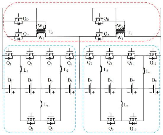
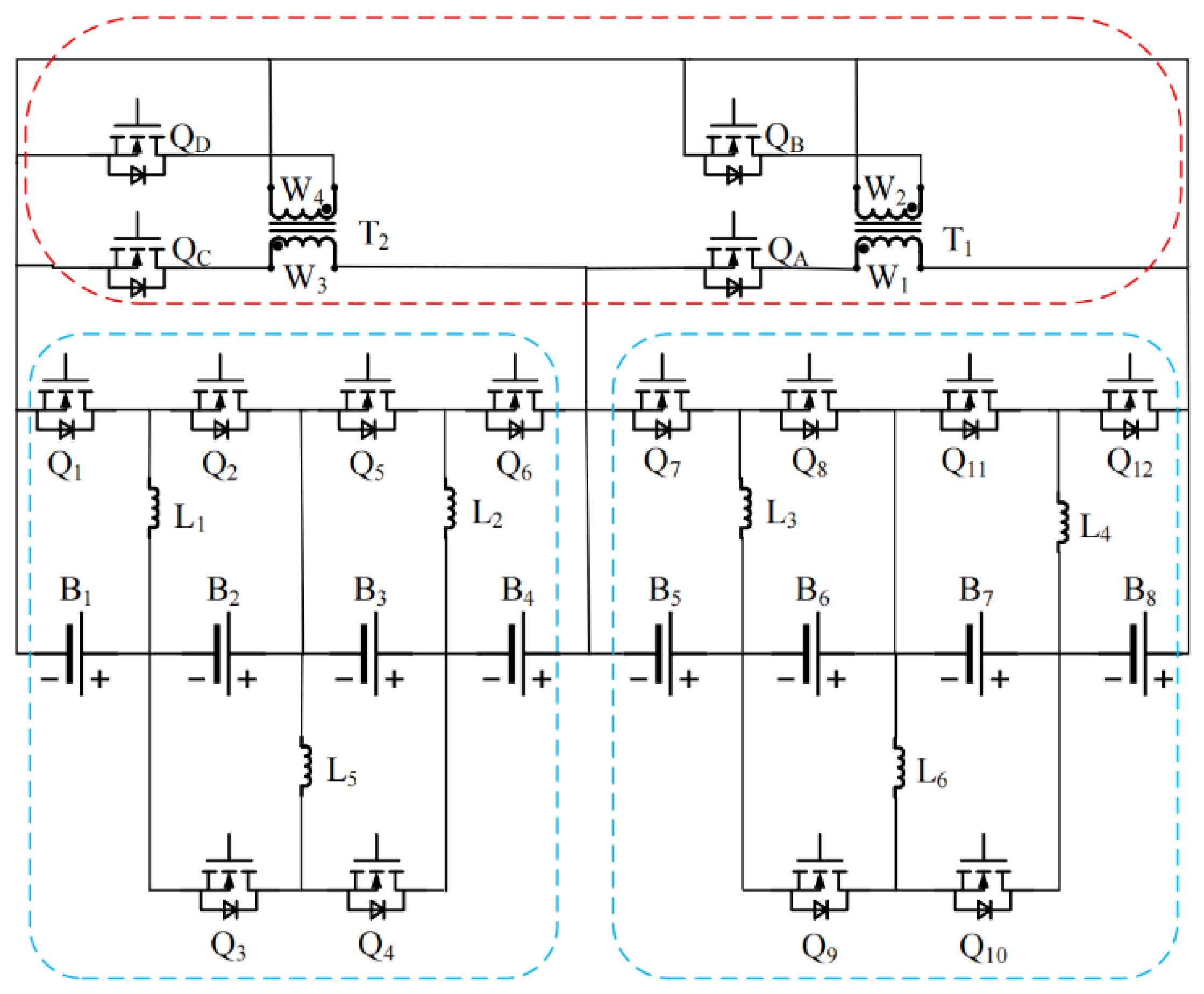
The conventional single-layer Buck–Boost topology suffers from a long energy-transfer path and low efficiency. To address this issue, a hierarchical balancing topology is proposed in this paper, where the battery pack is managed in groups, as shown in Figure 1. Using an eight-cell balancing circuit as an example, battery cells B1–B8 are connected to inductors L1–L7 and power switches Q1–Q14, all of which are implemented with metal–oxide–semiconductor field-effect transistors (MOSFETs).
Figure 1.
Internal Structure of the Improved Hierarchical Topological Model.
Intra-group balancing is realized by a bidirectional Buck–Boost converter, enabling bidirectional energy transfer between adjacent cells with a short transfer path and high efficiency. Inter-group balancing is implemented using a bidirectional flyback converter. Each submodule is equipped with a transformer (T1, T2); by controlling the switching states of QA–QD on the primary and secondary windings W1–W4, energy can be flexibly transferred between different modules and the battery groups. Compared with conventional single-layer topologies, the hierarchical structure not only enables energy transfer between adjacent cells but also facilitates inter-module energy redistribution. By significantly shortening energy transfer paths, the proposed structure overcomes the limitations associated with balancing non-adjacent cells, thereby effectively improving balancing speed and enhancing the state-of-charge consistency of EV power battery packs.
2.2. Group-Internal Balancing Circuit
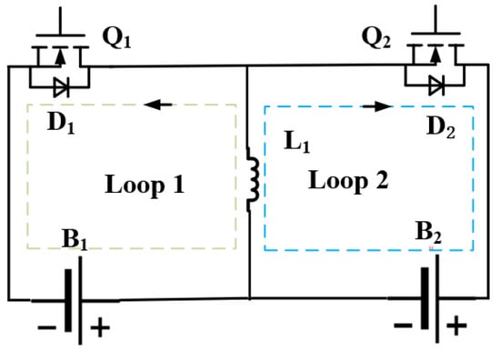
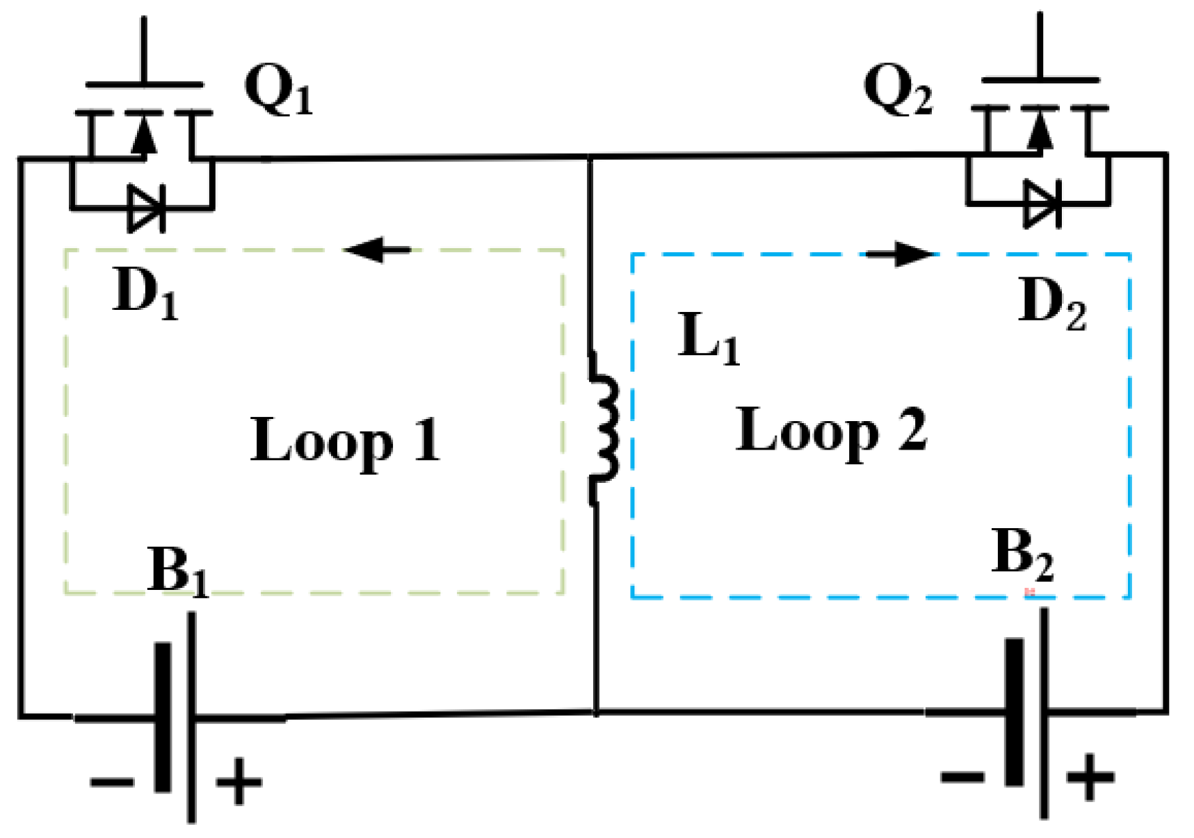
The intra-module equalization circuit employs a bidirectional Buck–Boost converter, as shown in Figure 2.
Figure 2.
Intra-group Buck–Boost Balancing Circuit.
The most fundamental balancing unit in a Buck–Boost converter consists of lithium batteries B1 and B2, balancing inductor L1, MOSFET switches Q1 and Q2, and freewheeling diodes D1 and D2. L1 functions as an energy storage and transfer component. Controlled by a pulse width modulation (PWM) signal, it switches transistors Q1 and Q2 on and off, enabling bidirectional energy flow within the converter inductor. This ensures charge equilibrium among individual cells within the battery pack. This paper assumes battery B1 has a higher state of charge (SOC) than battery B2. The entire balancing process comprises two phases: discharging B1 and charging B2. Let d denote the duty cycle of the switch control signal (PWM signal), ranging from 0 to 1; T represents the switching period of the control signal. When switch Q1 is turned on by the PWM signal, freewheeling diode D1 blocks reverse voltage, allowing inductor current IL1 to rise linearly and store energy as magnetic energy within the inductor. At the moment switch Q1 turns off, the current reaches its peak value.
The inductive current at time t is
In the equation, is the voltage across B1.
The inductive current reaches its maximum value at time . The peak current in one cycle is
During one switching cycle, since the current changes nearly linearly, the average discharge current flowing through battery B1 is
When switch transistor Q1 turns off, the current stored in inductor L1 cannot change abruptly. At this point, the electrical energy in the inductor is transferred to battery B2 in the form of current through freewheeling diode D2. The switch transistor continuously switches on and off until the two batteries are balanced.
In the charging circuit, the current through inductor L1 is
In the equation, is the voltage across the terminals of B2.
Similarly, the average current that the inductor charges battery B2 with during one switching cycle is
Conversely, when control switch transistor Q2 conducts, energy transfers from battery B2 to B1. By controlling other individual cells in this manner, the balancing issue between adjacent cells can be resolved.
2.3. Inter-Group Balancing Circuit
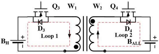
The inter-module balancing topology employs a bidirectional flyback converter. Utilizing a flyback converter structure provides excellent electrical isolation, ensuring overall battery pack safety. Additionally, each module operates independently, achieving faster response times compared to traditional Buck–Boost converters. The inter-module balancing circuit comprises a coupling inductor, diodes D3 and D4, and MOSFET power switches Q3 and Q4. The inter-module balancing module treats B1, B2, B3, and B4 as a single battery pack, denoted as BH; the entire battery pack is denoted as BALL. The primary and secondary windings of the coupling inductor are labeled W1 and W2, respectively.
The inter-module bidirectional flyback converter equalization circuit is illustrated in Figure 3.
Figure 3.
Balanced Circuit for Inter-Group Flyback Converters.
This paper assumes that the BH group has the highest SOC value, and the main controller issues a PWM signal to control the switching transistor Q3 to turn on. At this point, the entire voltage of the BH group is applied to the primary winding W1 of the transformer, magnetizing the transformer core. Utilizing the bidirectional energy flow characteristic of the flyback converter, when Q3 is on, the BH group charges the primary winding W1 of the coupling inductor. The current path is indicated by Loop 1 in Figure 3.
The primary current of the coupled inductor is
In the formula: is the voltage of battery pack BH; is the inductance value of the primary-side inductor. The primary and secondary currents reach their maximum values at time . Within one cycle, the maximum currents and in the primary and secondary inductors are respectively:
In the formula: N1 and N2 represent the number of turns in the primary winding and secondary winding of the coupling inductor, respectively.
When switch transistor Q3 turns off, the current path in the primary winding is interrupted. The stored energy in the transformer induces a voltage with positive polarity on the top and negative polarity on the bottom through electromagnetic induction in the secondary winding, forcing the diode to conduct. The current path is shown as Loop 2 in Figure 3. The secondary winding W2 of the coupled inductor charges the battery pack . The coupled secondary current is
At this point, the energy stored in the transformer is delivered to the entire battery pack through the freewheeling diode, thereby achieving the purpose of transferring energy to the group with lower SOC. When the number of battery groups is increased, parallel discharging of multiple groups can be realized by closing the control switches, making the equalization advantages of this topology even more pronounced.
Taking a battery pack consisting of four groups of sixteen cells as an example, the key parameters for the improved topology are designed as follows:
According to Formula (10), the inductance value in the Buck–Boost balancing circuit is obtained as
In the equation, represents the battery voltage; denotes the duty cycle; indicates the switching frequency; l signifies the current ripple; calculations yield ≈ 200 .
According to Formula (11), the value of excitation inductance m is obtained
In the equation, represents the terminal voltage of the series battery pack; max denotes the maximum duty cycle during operation of the flyback transformer, with max = 0.6 adopted in the calculation; signifies the duty cycle period. Calculations yield m ≈ 200 .
Based on the relationship between the input and output voltages of the transformer in the inter-module balancing circuit, the turns ratio of the transformer can be calculated as
In the equation, represents the primary-side voltage, and represents the secondary-side voltage. The primary-to-secondary turn ratio of the transformer is 1:3.
3. Materials and Methods
3.1. Multi-Stage Balancing Control Strategy
From the perspective of energy scheduling, conventional active balancing schemes—such as adjacent-cell energy transfer, centralized multi-winding-transformer architectures, and grouped serial scheduling—commonly encounter scalability and efficiency bottlenecks in large-scale series-connected systems. As the number of series cells increases, adjacent-transfer structures cannot redistribute energy between non-adjacent cells or across modules, resulting in long balancing paths and slow convergence. Centralized multi-winding structures, in turn, incur substantial increases in volume, cost, and implementation complexity as the number of groups grows.
Accordingly, the control strategy of the proposed balancing circuit is divided into intra-module and inter-module control. Considering that each group contains only four series-connected cells that are physically adjacent, an intra-group bidirectional Buck–Boost direct energy transfer strategy is adopted. This strategy is based on comparisons between adjacent cells and is assisted by the group-average value, thereby reducing control complexity and achieving fast convergence. For inter-group balancing, because the proposed design employs a set of independent flyback converters that can operate in parallel, conventional strategies based on global sorting and pairwise energy transfer often fail to fully exploit the available parallelism and introduce additional computation and scheduling overhead.
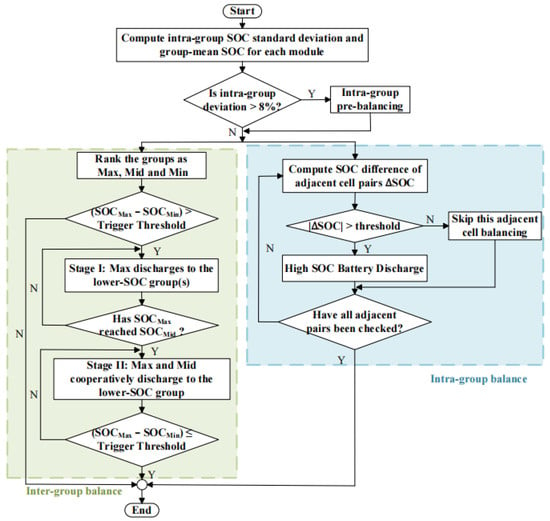
To this end, this paper proposes a multi-stage cooperative balancing strategy tailored to the hardware architecture to maximize the utilization of parallel power channels and improve balancing speed. The controller uses the SOC of each cell as a criterion: first, it calculates the standard deviation of SOC within a group. When the variance within a group exceeds 8%, it first performs intra-group pre-equalization to reduce the SOC disparity among cells within the group, followed by phased equalization. When the variance within a group is less than 8%, intra-group and inter-group equalization are performed simultaneously to accelerate the equalization process. The control framework for the equalization strategy is shown in Figure 4.
Figure 4.
Balanced Control Strategy Framework.
At the start of intra-group balancing, the process first performs a pairwise comparison of three adjacent cell pairs. The corresponding balancing channel is activated only when the SOC difference between adjacent cells exceeds a predefined threshold. To prevent excessive balancing or oscillatory behavior near the threshold, this paper further introduces the group average SOC as an auxiliary constraint: energy transfer from a higher-SOC cell to its adjacent lower-SOC counterpart is permitted only if the donor cell’s SOC is above the group average; otherwise, it remains idle. Through the three-layer criterion—standard deviation triggering, adjacent-difference localization, and mean-value oscillation suppression—the intra-group balancing prioritizes reducing dispersion within the group and improving cell consistency. Meanwhile, the average SOC difference between groups is reserved for the second-layer inter-group flyback balancing. This division of tasks enhances the stability and convergence efficiency of the two-tier coordinated control system.
For inter-group balancing, the mean SOC of each group is used as the balancing indicator. The mean SOC values of the four groups are calculated and sorted in descending order to identify the highest-, second-highest-, second-lowest-, and lowest-SOC groups. Inter-group balancing is initiated when the SOC difference between the highest and lowest groups exceeds the threshold; otherwise, all inter-group channels remain disabled to mitigate ineffective energy circulation and reduce switching losses.
After balancing is triggered, a cooperative discharging mechanism based on a progressively expanding source-side concept is adopted in this study.
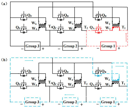
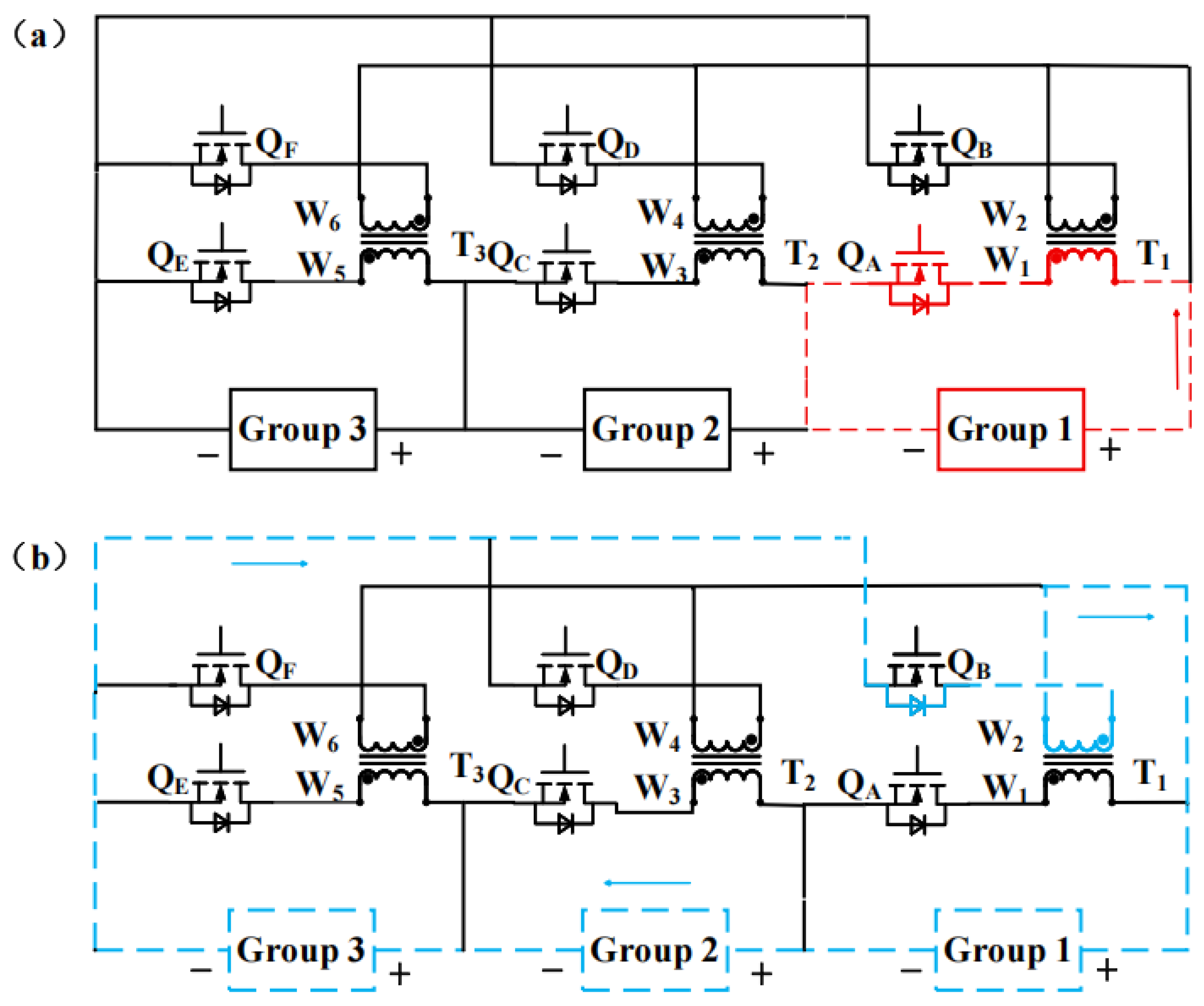
Stage I: Only the group with the highest SOC participates as the energy-supplying source, operating at full capacity to rapidly increase the SOC of the lower-SOC group(s). The corresponding energy flow paths are illustrated in Figure 5a,b.
Figure 5.
(a) Energy flow during the Stage I discharging process. (b) Energy flow during the Stage I charging process.
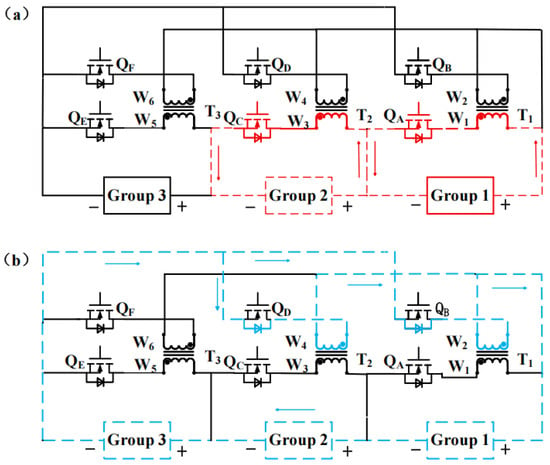
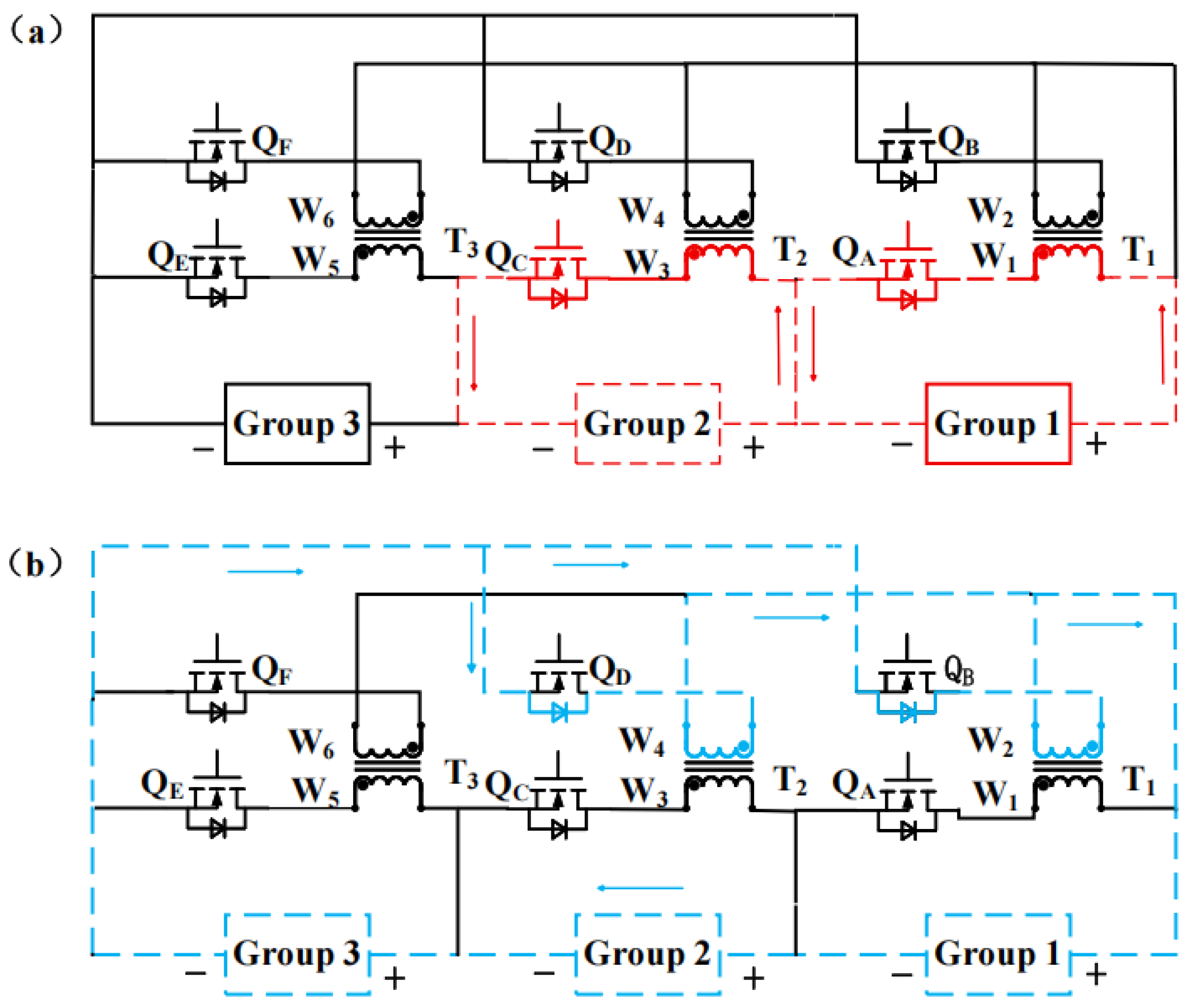
Stage II: After the highest-SOC group is balanced with the second-highest-SOC group, the two groups cooperate as energy sources to perform coordinated discharging, thereby accelerating the overall balancing process. The corresponding energy-transfer paths are shown in Figure 6a,b.
Figure 6.
(a) Energy flow during the Stage II discharging process. (b) Energy flow during the Stage II charging process.
Compared with a single-source-group scheme, the proposed method first equalizes the source-side groups and then progressively increases the number of groups supplying energy in parallel. This design not only avoids ineffective energy transfer and frequent power-flow reversal caused by large discrepancies among source-side groups, but also fully exploits the parallel capability of the independent flyback converters, thereby improving power utilization and dynamic response in inter-group balancing. In practical implementations, each flyback channel can be coordinated with current limiting and a hysteresis-based stage-switching mechanism to suppress frequent reconfiguration induced by ranking fluctuations and to ensure safe and stable operation.
3.2. SOC Estimation
To improve the efficiency of battery pack equalization, accurate estimation of the State of Charge (SOC) is essential. Achieving high-precision estimation of the current SOC requires the establishment of an equivalent model capable of accurately simulating the internal reaction characteristics of the battery. Commonly used battery models include the internal resistance model, the resistance-capacitance (RC) model, the Thevenin model, and the Partnership for a New Generation of Vehicles (PNGV) model, among others.
3.2.1. Establishment of Equivalent Circuit Models
To achieve accurate estimation of the state of charge (SOC) in electric vehicle battery management systems, this paper employs a second-order RC equivalent circuit model to characterize individual battery cells. Compared with first-order models, the second-order equivalent circuit model more effectively captures battery polarization effects and terminal voltage dynamics under EV driving conditions, while still satisfying the computational efficiency requirements of onboard applications. Accordingly, this method has been extensively adopted in EV power-battery modeling and state-estimation research.
Here, represents the battery current, while and denote the parallel voltages across the terminals.
The formula for calculating SOC can be expressed as
In the formula: represents the SOC value at time ; denotes the rated capacity of the battery; indicates the charging and discharging efficiency of the circuit.
The aforementioned second-order RC state-space model provides a modeling foundation for the subsequent state of charge (SOC) estimation algorithm based on the unscented Kalman filter. Moreover, it lays the groundwork for state monitoring and control strategy design in electric vehicle power battery systems under complex driving conditions.
3.2.2. SOC Estimation Method Based on UKF
In this study, the SOC of each individual cell is selected as the equalization objective; therefore, acquiring accurate SOC values is crucial for achieving effective equalization. Based on the aforementioned second-order RC equivalent circuit state-space model, this paper employs the unscented Kalman filter (UKF) algorithm to estimate the state of charge (SOC) of electric vehicle (EV) power batteries. Given that EV power batteries exhibit pronounced nonlinear characteristics during actual operation, the UKF estimates the state of the nonlinear system via unscented transformation, thereby avoiding the linearization of the system model and demonstrating favorable numerical stability and estimation accuracy. As documented in the literature [25], this method maintains high-precision representation and reliable performance in laboratory environments. It not only exhibits strong robustness against initial SOC fluctuations and random noise interference, but also has shown continuous improvements in related performance.
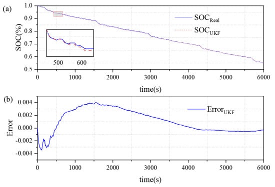
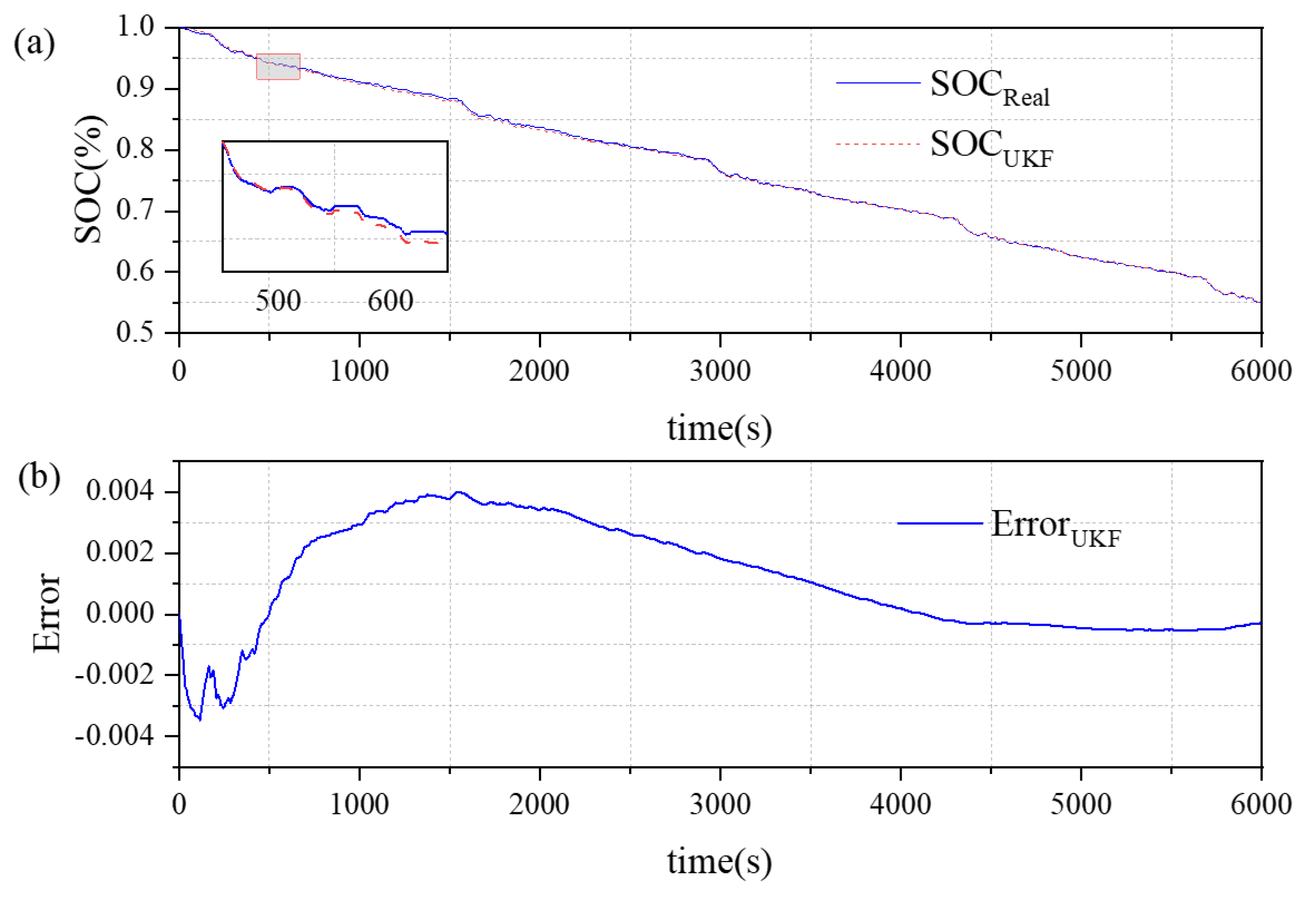
The estimation results and their corresponding errors are presented in Figure 7a,b. The maximum estimation error of the UKF remains within 0.4%, which demonstrates the algorithm’s high robustness and its ability to accurately estimate the SOC. This performance meets the SOC estimation accuracy requirements of battery management systems for electric vehicles.
Figure 7.
(a) SOC estimation curves based on the UKF algorithm. (b) SOC estimation error.
4. Results
4.1. Establishment of Experimental Models
In the experimental validation of existing active battery balancing strategies, many studies still employ small-scale series strings consisting of four or six cells, owing to practical constraints such as prototype hardware complexity, measurement and control cost, and experimental repeatability. For example, some works explicitly use a four-cell series pack as the design and verification platform for a balancing system, or demonstrate the control performance using four cells in simulation. Although such small-scale validation can demonstrate feasibility, the results often fail to adequately capture the key challenges that emerge as the number of cells increases, including the amplified inter-group energy-scheduling overhead with scale, the variations in energy-transfer paths and convergence speed in long series strings, as well as parallel-channel utilization and the risk of frequent reconfiguration.
Accordingly, this study adopts a 16-cell series configuration to substantially increase the validation scale while keeping the simulation complexity manageable, thereby providing a more application-relevant and convincing assessment of the scalability and extensibility of the proposed staged inter-group balancing strategy. On the one hand, a 16-cell pack is sufficiently large to reveal scheduling and convergence issues that become prominent only at larger scales. On the other hand, 16 cells facilitate a modular grouping structure, enabling a clear demonstration of how the proposed strategy naturally scales within a grouped architecture and providing a direct structural basis for further extension to a larger number of submodules.
To verify the effectiveness of the proposed topology, the simulations were performed on a desktop computer (HP Z1 Entry Tower G6) equipped with an Intel Core i7-10700 processor and Intel UHD Graphics 630, running a 64-bit operating system. An equivalent energy-storage battery-pack model consisting of 16 lithium-ion cells was developed in the MATLAB/Simulink 2024a environment. The pack was composed of single cells with a nominal voltage of 3.7 V and a rated capacity of 3.3 Ah. The balancing-module activation threshold was set to 3%, and the switching frequency f was set to 10 kHz.
To demonstrate the advanced nature of the topology presented in this paper, simulation models were established for both the traditional single-layer Buck–Boost balancing circuit and the improved hierarchical balancing circuit for comparative experiments.
The key parameter values of Model 4 are listed in Table 1.
Table 1.
Key parameter values of Model 4.
4.2. Equilibrium Topology Validation
The simulation must account for various typical operating conditions of electric vehicles, including static balancing, charging balancing, and discharging balancing. To demonstrate the superiority of the topology proposed in this paper, we constructed a traditional single-stage Buck–Boost balancing circuit (Model 1), a two-stage multi-winding centralized balancing circuit with a Buck–Boost balancing circuit at the lower stage based on Reference [26] (Model 2), and a two-stage distributed balancing circuit (Model 3) [27], and the improved hierarchical balancing circuit proposed in this paper (Model 4). These simulation models were established for comparative experiments.
Due to the intrinsic self-discharge behavior of lithium-ion batteries, the impact of self-discharge becomes more pronounced during long-term storage than during short-term inactivity. Timely monitoring of SOC inconsistency among cells enables static balancing, thereby mitigating the adverse effects of self-discharge. In this study, the initial SOCs of the 16 cells were set to 63–93% with a uniform increment of 2%.
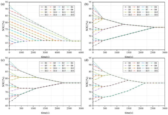
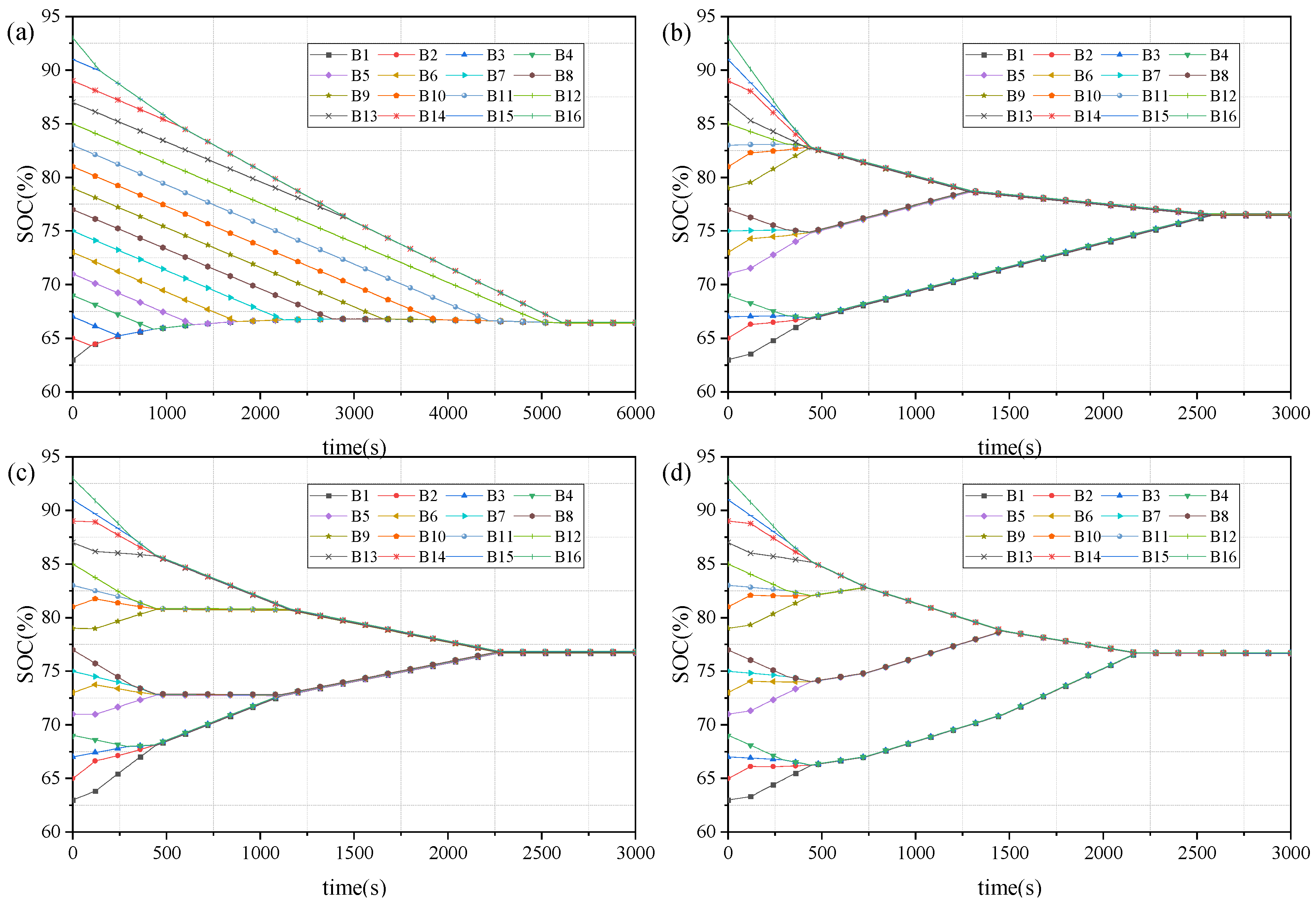
As shown in Figure 8, the four models reached equilibrium after 5200 s, 2580 s, 2272 s, and 2181 s, respectively. The equilibrium circuit proposed in this study achieved the shortest equilibrium time, reducing the equilibrium time by 58.09%, 15.47%, and 4.01% compared to the first three models, respectively.
Figure 8.
The equalization processes of the four circuits under static conditions: (a) Model 1; (b) Model 2; (c) Model 3; and (d) Model 4.
As shown in Table 2, after the four models reached a balanced state, their ranges were 0.21%, 0.17%, 0.19%, and 0.11%, respectively. The range of Model 4 after balancing was 0.11%, which is 0.1, 0.06, and 0.08 percentage points lower than that of the other three models, respectively. After balancing, the variance of the proposed model is 0.0014%, corresponding to reductions of 0.0058, 0.0017, and 0.0013 percentage points, respectively, and is significantly lower than that of the other three models. The small range and low variance of Model 4 ensure stable system performance under various operating conditions. While maintaining high balancing efficiency, it provides optimal stability and reliability, which is crucial for application scenarios requiring high consistency, such as electric vehicle battery management systems.
Table 2.
Comparison of Quiescent Experimental Data for Four Types of Balanced Circuits.
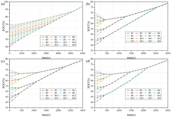
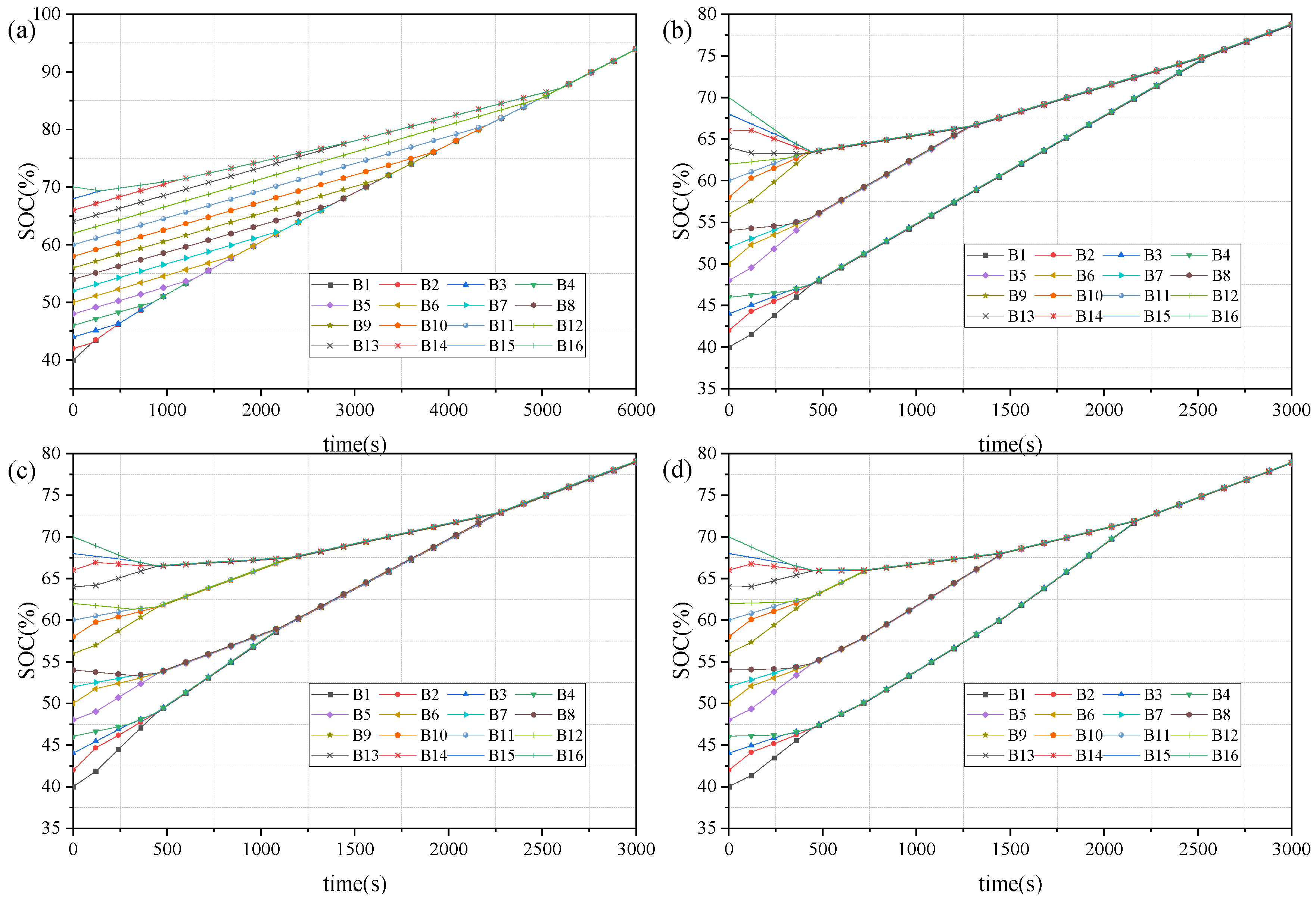
During charging, the initial SOCs of the 16 cells were set to 40–70% with a uniform increment of 2%. The pack was charged under a 1 A constant-current (CC) condition for the charging-balancing test. The corresponding simulation results are presented in Figure 9.
Figure 9.
The equalization processes of the four circuits under charging conditions: (a) Model 1; (b) Model 2; (c) Model 3; and (d) Model 4.
As shown in Figure 9, the time required for the four models to reach a balanced state is 5183 s, 2563 s, 2266 s, and 2179 s, respectively. The balancing circuit proposed in this study has the shortest balancing time, which is reduced by 57.97%, 14.98%, and 3.84% compared to the other three models, respectively. As shown in Table 3, after the four models reached a balanced state, their ranges were 0.22%, 0.17%, 0.18%, and 0.11%, respectively. Moreover, the variance of the proposed model after balancing is 0.0013%, demonstrating a more prominent consistency advantage.
Table 3.
Comparison of Charging Experimental Data for Four Types of Balanced Circuits.
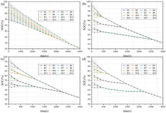
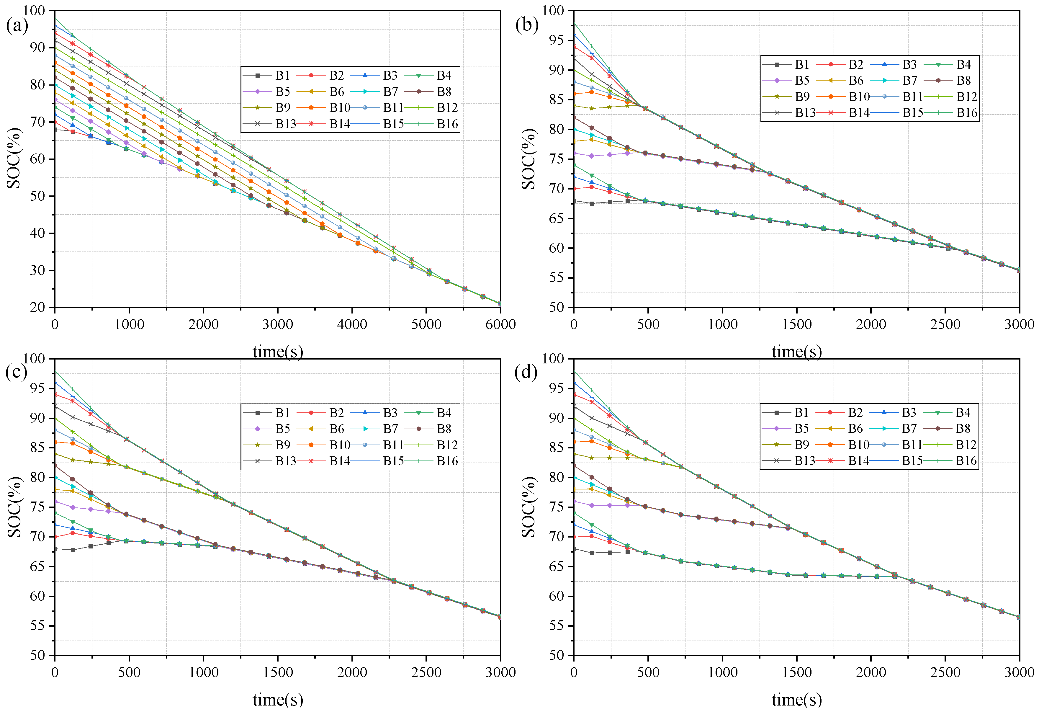
During discharging, the initial SOCs of the 16 cells were set to 68–98% with a uniform increment of 2%. The pack was discharged under a 1 A constant-current (CC) condition for the discharging-balancing test. The corresponding simulation results are shown in Figure 10.
Figure 10.
The equalization processes of the four circuits under discharging conditions: (a) Model 1; (b) Model 2; (c) Model 3; and (d) Model 4.
As shown in Figure 10, the four models require 5239 s, 2583 s, 2285 s, and 2197 s, respectively, to reach a balanced state. Compared to the other three models, the balancing model proposed in this study reduces the balancing time by 58.06%, 14.94%, and 3.85%, respectively. As shown in Table 4, after the four models achieve a balanced state, their ranges are 0.20%, 0.16%, 0.19%, and 0.12%, respectively. Compared to the other three models, the reductions are 0.08, 0.04, and 0.07 percentage points, respectively. Furthermore, the variance of the proposed model after balancing is 0.0012%, which is significantly lower than that of the other three models.
Table 4.
Comparison of Discharge Experimental Data for Four Types of Balanced Circuits.
5. Discussion
The simulation results under the three operating conditions (rest, charging, and discharging) indicate that the differences among the four balancing schemes in balancing speed and energy loss fundamentally arise from variations in energy-transfer path length, achievable parallel balancing capability, and topology scalability. Model 1 relies on stepwise energy transfer between adjacent cells; cross-end compensation requires multi-hop relay transfer, leading to the longest balancing time and pronounced cumulative losses. Under practical conditions, factors such as SOC estimation errors and component non-idealities may further deteriorate its convergence behavior. Model 2 can rapidly reduce the mismatch between the highest- and second-highest-SOC groups in the early stage, reflecting the relatively high power-utilization capability of centralized topologies under large initial imbalances. However, once the two highest groups become nearly equal, effective parallelism decreases due to time-division multiplexing. Moreover, as the system scales up, the volume and cost of multi-winding transformers increase substantially, limiting scalability and techno-economic feasibility in large-scale series-connected applications.
Model 3 establishes direct energy-transfer paths between adjacent battery groups, shortening cross-end compensation from a multi-hop relay to a group-to-group transfer. Consequently, the convergence speed is markedly improved; meanwhile, the shorter transfer path and fewer conversion stages result in comparatively lower overall losses. Model 4 further introduces a hierarchical design in which each balancing group is equipped with a dedicated flyback transformer, enabling more direct energy redistribution at both intra-group and inter-group scales and reducing the path length of cross-level energy transport at the topology level. Combined with the proposed multi-stage balancing strategy, the system reaches a balanced state on the order of ~2100 s, demonstrating the convergence acceleration achieved by transfer-path reduction together with staged control progression.
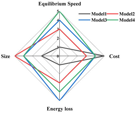
Taking the rest condition as an example, the comparison of mean values can serve as an auxiliary indicator of efficiency and loss. Model 1 exhibits the lowest mean value, indicating the poorest energy utilization and the largest cumulative loss due to multi-stage conversion and long-path energy shuttling. Model 3 achieves the lowest energy loss because it features the shortest transfer link and fewer conversion stages. For the proposed Model 4, introducing a flyback module in each group increases fixed component-related losses, resulting in a slightly higher loss than Model 3; however, because it substantially shortens the transfer path and reduces ineffective bidirectional energy circulation, its overall loss remains lower than that of Model 2. Overall, Model 4 provides a more favorable trade-off between balancing speed and energy loss, while offering improved scalability and greater practical implementation potential.
The results above demonstrate that the proposed method can meet the operational requirements of electric vehicle power batteries under complex operating conditions, thereby providing effective support for condition monitoring and control in electric vehicle battery management systems.
To complement the performance study, the incremental hardware cost of the four topologies is estimated using publicly available unit prices from major electronic-component distributors. Taking the rest condition as an example, and assuming identical remaining components and test equipment, the additional manufacturing cost required by each topology due to its specific hardware characteristics is analyzed. The comparison results are shown in Table 5. A 16-cell pack divided into four balancing groups is used as the case study, and the electronic-component prices used for the calculation are referenced to the 2025 market level. As shown in Figure 11, each parameter is fuzzified into five linguistic grades, where “1”, “2”, “3”, “4”, and “5” denote worst, poor, neutral, good, and best performance, respectively.
Table 5.
Static Equilibrium Test Data.
Figure 11.
Performance Comparison Chart.
6. Conclusions
This study addresses the consistency issue in series-connected lithium-ion battery packs by proposing and validating a hierarchical active equalization system through simulation analysis. In the proposed architecture, bidirectional Buck–Boost converters are employed for balancing within each group, while distributed Flyback converters are used for balancing between groups, thereby shortening the energy transfer path and enabling direct energy transfer across modules. Furthermore, the control strategy combines a lightweight algorithm for intra-group balancing with a multi-stage mode for inter-group balancing, which effectively reduces computational complexity and accelerates the balancing speed. As a result, the proposed method demonstrates good scalability, robustness, and balancing efficiency for long series-connected battery systems.
Limitations and Future Work: This study is based on simulation verification and does not account for practical constraints such as temperature rise and electromagnetic compatibility. The next step will involve building a physical experimental platform for performance testing and exploring the application of intelligent equalization algorithms in high-voltage, high-capacity systems.
Author Contributions
Conceptualization, Z.T. and X.Q.; methodology, X.Q.; software, X.Q. and N.D.; validation, L.C., X.Q. and Q.X.; formal analysis, Q.X.; investigation, Q.X.; resources, N.D.; data curation, X.Z.; writing—original draft preparation, X.Q.; writing—review and editing, L.C.; visualization, X.Z.; supervision, L.C.; project administration, X.Z.; funding acquisition, N.D. All authors have read and agreed to the published version of the manuscript.
Funding
This research was funded by the Natural Science Foundation of Chongqing Municipality, China (No. CSTB2025NSCQ-WZQLHJJMSX0009).
Data Availability Statement
The original contributions presented in this study are included in the article. Further inquiries can be directed to the corresponding author(s).
Conflicts of Interest
Xiaojiang Zou is employees of Battery Division, Chongqing Hangying Automobile Manufacturing Co., Ltd., Chongqing. The remaining authors declare that the research was conducted in the absence of any commercial or financial relationships that could be construed as a potential conflict of interest.
References
- Kumar, R.R.; Bharatiraja, C.; Udhayakumar, K.; Devakirubakaran, S.; Sekar, K.S.; Mihet-Popa, L. Advances in Batteries, Battery Modeling, Battery Management System, Battery Thermal Management, SOC, SOH, and Charge/Discharge Characteristics in EV Applications. IEEE Access 2023, 11, 105761–105809. [Google Scholar] [CrossRef] [Scilit]
- Rouholamini, M.; Wang, C.; Nehrir, H.; Hu, X.; Hu, Z.; Aki, H.; Zhao, B.; Miao, Z.; Strunz, K. A Review of Modeling, Management, and Applications of Grid-Connected Li-Ion Battery Storage Systems. IEEE Trans. Smart Grid 2022, 13, 4505–4524. [Google Scholar] [CrossRef] [Scilit]
- Al-Smadi, M.K.; Abu Qahouq, J.A. Flexible Multi-Battery System with Active Balancing and Voltage Regulation. IEEE Access 2025, 13, 52983–52994. [Google Scholar] [CrossRef] [Scilit]
- Kurkin, A.; Chivenkov, A.; Aleshin, D.; Trofimov, I.; Shalukho, A.; Vilkov, D. Battery Management System for Electric Vehicles: Comprehensive Review of Circuitry Configuration and Algorithms. World Electr. Veh. J. 2025, 16, 451. [Google Scholar] [CrossRef] [Scilit]
- Yang, S.; Zhang, S. Energy Balance Control of Multi Group Lithium Ion Batteries Under Internet of Things Technology. IEEE Access 2024, 12, 102784–102797. [Google Scholar] [CrossRef] [Scilit]
- Manjunath, K.; Kalpana, R.; Singh, B.; R, K. A Two-Stage Module Based Cell-to-Cell Active Balancing Circuit for Series Connected Lithium-Ion Battery Packs. IEEE Trans. Energy Convers. 2023, 38, 2282–2297. [Google Scholar] [CrossRef] [Scilit]
- Lee, S.; Noh, G.; Ha, J.-I. Reconfigurable Power Circuits to Series or Parallel for Energy-Balanced Multicell Battery Pack. IEEE Trans. Ind. Electron. 2023, 70, 3641–3651. [Google Scholar] [CrossRef] [Scilit]
- Hwu, K.-I.; Lin, Y.-H.; Shieh, J.-J. Active Battery Voltage Equalization Based on Chain-Loop Comparison Strategy. Energies 2024, 17, 5156. [Google Scholar] [CrossRef] [Scilit]
- Zhao, Z.; Hu, H.; He, Z.; Iu, H.H.-C.; Davari, P.; Blaabjerg, F. Power Electronics-Based Safety Enhancement Technologies for Lithium-Ion Batteries: An Overview From Battery Management Perspective. IEEE Trans. Power Electron. 2023, 38, 8922–8955. [Google Scholar] [CrossRef] [Scilit]
- Chen, K.; Liu, L.; Zang, T.; Zhou, Y.; Yan, Z.; Xu, Y.; Xu, B.; Zhang, P.; Cai, C. Double-Layer Multiwinding Transformer-Based Modular-Integrated Equalizer for Extended Battery String. IEEE Trans. Power Electron. 2024, 39, 2767–2776. [Google Scholar] [CrossRef] [Scilit]
- Jiang, W.; Zhou, F. Active Battery Balancing System for High Capacity Li-Ion Cells. Energies 2025, 18, 6371. [Google Scholar] [CrossRef] [Scilit]
- Chen, J.; Behal, A.; Li, Z.; Li, C. Active Battery Cell Balancing by Real-Time Model Predictive Control for Extending Electric Vehicle Driving Range. IEEE Trans. Automat. Sci. Eng. 2024, 21, 4003–4015. [Google Scholar] [CrossRef] [Scilit]
- La, P.-H.; Choi, S.-J. Direct Cell-to-Cell Equalizer for Series Battery String Using Switch-Matrix Single-Capacitor Equalizer and Optimal Pairing Algorithm. IEEE Trans. Power Electron. 2022, 37, 8625–8639. [Google Scholar] [CrossRef] [Scilit]
- Zhou, G.; Zhang, X.; Gao, K.; Tian, Q.; Xu, S. Two-Mode Active Balancing Circuit Based on Switched-Capacitor and Three-Resonant-State LC Units for Series-Connected Cell Strings. IEEE Trans. Ind. Electron. 2022, 69, 4845–4858. [Google Scholar] [CrossRef] [Scilit]
- Luo, L.; Wang, J.; Zhou, Y.; Ci, S. Topology, Modeling, and Optimization of Switched-Capacitor Equalizer Based on Multiplexing Technology for Multiple Battery Strings. IEEE Trans. Power Electron. 2025, 40, 11452–11466. [Google Scholar] [CrossRef] [Scilit]
- Karmakar, S.; Bohre, A.K.; Bera, T.K. Recent Advancements in Cell Balancing Techniques of BMS for EVs: A Critical Review. IEEE Trans. Ind. Appl. 2025, 61, 3468–3484. [Google Scholar] [CrossRef] [Scilit]
- Manjunath, K.; Kalpana, R.; Singh, B. A Modularized Two-Stage Active Cell Balancing Topology with Reduced Balancing Time for Series Connected Li-Ion Battery String. IEEE Trans. Ind. Appl. 2025, 61, 502–514. [Google Scholar] [CrossRef] [Scilit]
- Cai, C.; Nie, J.; Jiao, S.; Liu, S.; Wang, S.; Ma, L.; Shu, Z. An Active Isolated Battery Equalizer for 24-Cell Based on Soft-Switching Resonant Circuits. IEEE Trans. Ind. Electron. 2025, 72, 11320–11331. [Google Scholar] [CrossRef] [Scilit]
- Mai, R.; Xu, B.; Yan, Z.; Zhou, W.; Liu, L. A Compact-Size Multi-Winding Transformer-Based Discharge Equalizer for Electric Two-Wheelers and Three-Wheelers Vehicles Power Battery. IEEE Trans. Veh. Technol. 2022, 71, 4889–4897. [Google Scholar] [CrossRef] [Scilit]
- Dai, Y.; Zhang, L.; Yan, K.; Chen, Q.; Zhou, Z.; Zhou, K. An Integrated Cooperative Control Strategy for EVs Accessed Community Uninterruptible Power System. IEEE Trans. Intell. Veh. 2023, 8, 2482–2493. [Google Scholar] [CrossRef] [Scilit]
- Wu, H.; Chai, L.; Zhu, Z.-H.; Tian, Y.-C. Prescribed-Time Control for DC Microgrids with Battery Energy Storage Systems. IEEE Trans. Ind. Inform. 2024, 20, 11896–11907. [Google Scholar] [CrossRef] [Scilit]
- Guha, A.; Routh, B.; Prudhvi Velivela, N. Adaptive Extended Kalman Filtering Based State-of-Charge and Voltage Estimation of a Lithium-Ion Battery Using a Fractional-Order Model. IEEE Sens. J. 2024, 24, 26225–26234. [Google Scholar] [CrossRef] [Scilit]
- Izadi, Y.; Beiranvand, R. A Comprehensive Review of Battery and Supercapacitor Cells Voltage-Equalizer Circuits. IEEE Trans. Power Electron. 2023, 38, 15671–15692. [Google Scholar] [CrossRef] [Scilit]
- Zeng, Y.; Zhang, Q.; Liu, Y.; Guo, H.; Zhang, F.; You, S. Distributed Unified Controller Design for Parallel Battery Storage System in DC Shipboard Microgrid. IEEE Trans. Power Syst. 2024, 39, 546–563. [Google Scholar] [CrossRef] [Scilit]
- Lin, J.; Yang, X.; Zhou, J.; Wang, G.; Liu, J.; Yuan, Y. Algorithm of BPNN-UKF Based on a Fusion Model for SOC Estimation in Lithium-ion Batteries. IET Power Electron. 2023, 16, 856–867. [Google Scholar] [CrossRef] [Scilit]
- Liu, L.; Xu, B.; Yan, Z.; Zhou, W.; Li, Y.; Mai, R.; He, Z. A Low-Cost Multiwinding Transformer Balancing Topology for Retired Series-Connected Battery String. IEEE Trans. Power Electron. 2021, 36, 4931–4936. [Google Scholar] [CrossRef] [Scilit]
- Tavakoli, A.; Khajehoddin, S.A.; Salmon, J. Control and Analysis of a Modular Bridge for Battery Cell Voltage Balancing. IEEE Trans. Power Electron. 2018, 33, 9722–9733. [Google Scholar] [CrossRef] [Scilit]

Disclaimer/Publisher’s Note: The statements, opinions and data contained in all publications are solely those of the individual author(s) and contributor(s) and not of MDPI and/or the editor(s). MDPI and/or the editor(s) disclaim responsibility for any injury to people or property resulting from any ideas, methods, instructions or products referred to in the content. |
© 2026 by the authors. Published by MDPI on behalf of the World Electric Vehicle Association. Licensee MDPI, Basel, Switzerland. This article is an open access article distributed under the terms and conditions of the Creative Commons Attribution (CC BY) license.