


Abstract
To improve the anti-slip performance and energy-efficient torque coordination of four-wheel-drive articulated tractors operating in hilly and mountainous terrains, this study proposes an integrated control framework that combines a 7-DOF tractor dynamics model, a GA-optimized fuzzy slip-ratio controller, and a three-level dynamic torque allocation strategy. First, a control-oriented full-vehicle dynamics model is established by integrating tractor body dynamics, wheel rotational dynamics, and the Dugoff tire model. Then, a fuzzy slip-ratio controller is designed using the slip-ratio tracking error and its rate of change as inputs, and its key parameters are optimized using a genetic algorithm. On this basis, a three-level dynamic torque allocation strategy is developed to coordinate the four in-wheel motors according to wheel-load distribution and slip-related constraints. MATLAB/Simulink (version 2023a) simulations and hardware-in-the-loop (HIL) tests are carried out to validate the proposed strategy. Under the straight-line driving condition, the RMSE of the proposed GA-fuzzy controller is reduced from 0.02716 to 0.00897. Under the steering condition, the average RMSE is reduced from 0.02079 to 0.01003. In addition, under the torque-allocation validation condition, the average four-wheel RMSE is reduced from 0.29632 under equal torque allocation to 0.02159 under the proposed three-level dynamic torque allocation strategy. The results indicate that the proposed method can effectively maintain the slip ratio near its target value, suppress excessive slip and redundant torque output, and improve the anti-slip and energy-efficient performance of articulated tractors. More importantly, the study provides an integrated control framework that unifies GA-optimized slip regulation and three-level torque coordination specifically for four-wheel-drive articulated tractors.
1. Introduction
China is a major agricultural country with vast arable land. The arable land in hilly and mountainous areas accounts for one-third of the national total, yet its GDP only constitutes 30% of the national figure. A primary reason for this disparity is the underdevelopment of agricultural mechanization [1,2]. Unlike plain areas, the arable land in hilly and mountainous regions is characterized by small and scattered plots, significant terrain variations, and steep slopes [3,4]. The complex terrain of these areas poses severe challenges to the trafficability and power performance of tractors. However, articulated tractors exhibit excellent adaptability to narrow and uneven terrains, and have consequently garnered widespread attention from the academic community in recent years.
Due to adverse soil conditions, the driving wheels of tractors are highly susceptible to excessive slip during field operations, thereby impeding normal agricultural tasks. When the slip ratio stabilizes within a reasonable range, the tractor operates at a high tractive efficiency. Conversely, excessive slip of the driving wheels—particularly when the slip ratio exceeds 20%—drastically reduces operational efficiency. Furthermore, it exacerbates tire wear and energy consumption, and causes soil compaction, which ultimately hinders crop production [5]. Therefore, conducting research on the anti-slip drive and energy-saving control of tractors holds profound practical significance for enhancing the quality of field operations and safeguarding food security [6,7].
The core of anti-slip drive control lies in acquiring the real-time slip ratio of the tractor, which fundamentally relies on accurate tractor dynamics models and tire mechanics models [8]. M. Martelli et al. proposed a modular simulation model combining lumped-parameter and multibody dynamics approaches. By integrating the engine, drivetrain, vehicle body, and tire–soil interaction, the model is capable of simulating axle load transfer, slip, traction performance, and ride vibration comfort during operations such as plowing, and demonstrates significantly better performance than conventional models [9]. Y. J. Yang et al. developed a dynamic simulation model for a small crawler forestry tractor to investigate its rollover and overturning characteristics, and validated its safety performance under varying terrain and operational load conditions [10]. Bi Song et al. simplified tire dynamic parameters and established steady-state dynamic equations on slopes, alongside a real-time tire driving force estimation method for skid-steering wheeled robots; their experiments indicated that the accuracy of the real-time estimation method for tire vertical load reached 95% [11]. However, the aforementioned studies on dynamics models are not directly applicable to articulated tractors. Consequently, it is imperative to establish corresponding tractor dynamics models and tire models tailored to the unique structure of articulated steering.
Current research on the driving wheel slip ratio control of tractors is largely similar to that of passenger vehicles, encompassing methods such as fuzzy control, PID control, sliding mode variable structure control, and neural network control [12,13,14,15,16,17,18,19,20,21]. Extensive research has been conducted on tractor wheel-slip control in recent years. For example, Zhang Shuo from China Agricultural University proposed a nonlinear slip ratio control algorithm based on sliding mode variable structure, which can effectively maintain the slip ratio at a set value of 0.2 with minimal control error and high robustness [22]. Gupta, C. et al. developed a microcontroller-based embedded automatic slip–traction control system for a 2WD tractor. The system can adjust the tillage depth in real time, thereby improving traction performance by more than 9% and reducing operator fatigue [23]. R. R. De Melo et al. proposed a PI-based automatic slip control algorithm for a 2WD electric tractor, which enhances traction efficiency and reduces energy consumption by optimizing wheel speed and torque [24]. Serhat Soylu et al. proposed a tractor slip ratio control method based on fuzzy control, which automatically adjusts the working depth of tillage equipment according to the increment of the slip ratio difference [25]. However, most of the aforementioned studies are primarily applicable to plain areas and fail to achieve satisfactory control performance in the complex terrains and steep slopes of hilly and mountainous regions. Therefore, designing an anti-slip drive control strategy tailored for articulated tractors in hilly and mountainous terrains to mitigate slipping phenomena is of significant practical importance.
Energy-saving control technology aims to enhance the economic efficiency of tractors and plays a crucial role in the national Dual Carbon strategy. Current research on tractor energy-saving control mainly focuses on rule-based energy management strategies. However, these methods are highly dependent on empirical data and exhibit poor adaptability to complex operating conditions, making it difficult to achieve optimal control [26]. Consequently, research on optimal-control-based energy management strategies has progressively emerged. For instance, Luo et al. proposed a driving motor torque control strategy that dynamically identifies soil parameters while targeting the optimal slip ratio; this approach improved the overall vehicle speed stability by 37.50% and reduced the energy consumption of plowing operations by 9.51% [27]. Wang et al. introduced a dual-motor torque allocation strategy based on an improved Snake Optimizer (SO) algorithm, which demonstrated a 14.44% reduction in energy consumption during bench-simulated plowing operations [28]. Zhao Zihao et al. proposed an energy-saving control method based on a four-motor dual-coupled power system, which regulates torque by switching driving modes and torque allocation rules, resulting in a 3.76% decrease in electrical energy consumption compared to the average torque allocation strategy [29]. J. Zhang et al. proposed a predictive control strategy for an agricultural hybrid tractor. By optimizing torque distribution, the strategy addresses the problem of high fuel consumption and improves overall energy efficiency [30].
Although previous studies have made important progress in tractor dynamics modeling, slip-ratio control, and distributed-drive control, several gaps remain. First, most existing studies focus on conventional wheeled vehicles or non-articulated tractors, whereas control strategies specifically designed for four-wheel-drive articulated tractors are still limited. Second, slip control and torque allocation are usually investigated separately, and an integrated framework that can simultaneously coordinate wheel-slip regulation and torque distribution under uneven wheel-load conditions is still lacking. Third, although energy-saving control has received increasing attention, the relationship between slip suppression and efficient torque utilization has not been sufficiently clarified for articulated tractors operating on low-adhesion surfaces. To address these gaps, this paper establishes a 7-DOF control-oriented dynamic model for a four-wheel-drive articulated tractor, develops a GA-optimized fuzzy slip-ratio controller, and proposes a three-level dynamic torque allocation strategy for coordinating the four in-wheel motors according to dynamic wheel-load distribution and slip-related constraints. The proposed integrated framework is finally validated through MATLAB/Simulink simulation and hardware-in-the-loop testing. Therefore, the originality of this work lies in integrating slip-ratio regulation and dynamic torque coordination into a unified control framework for articulated tractors, rather than in the use of GA-fuzzy control alone.
2. Dynamics Model of the Articulated Tractor
The primary focus of this section is the establishment of the dynamics model for the articulated tractor, encompassing two main components: the full-vehicle dynamics model and the tire model. Considering the unique structure of the articulated tractor, its full-vehicle dynamics model is analyzed separately in the XY-plane and the Z-direction. Specifically, the analysis in the XY-plane is utilized to establish the equations of planar motion, which involve three degrees of freedom (DOFs): longitudinal, lateral, and yaw. Meanwhile, the mechanical analysis in the Z-direction is employed to formulate the vertical load equations for the four tires. Furthermore, it is necessary to establish the wheel rotational dynamics equations to calculate the wheel angular velocities. The Dugoff tire model is then adopted to determine the longitudinal and lateral forces. Finally, through the coupling of these elements, a comprehensive seven-degree-of-freedom (7-DOF) dynamics model for the distributed-drive articulated vehicle is established.
2.1. Seven-Degree-of-Freedom Dynamic Model of the Articulated Tractor
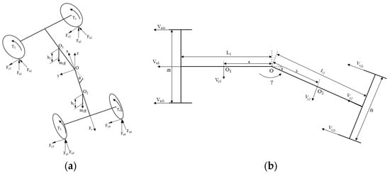
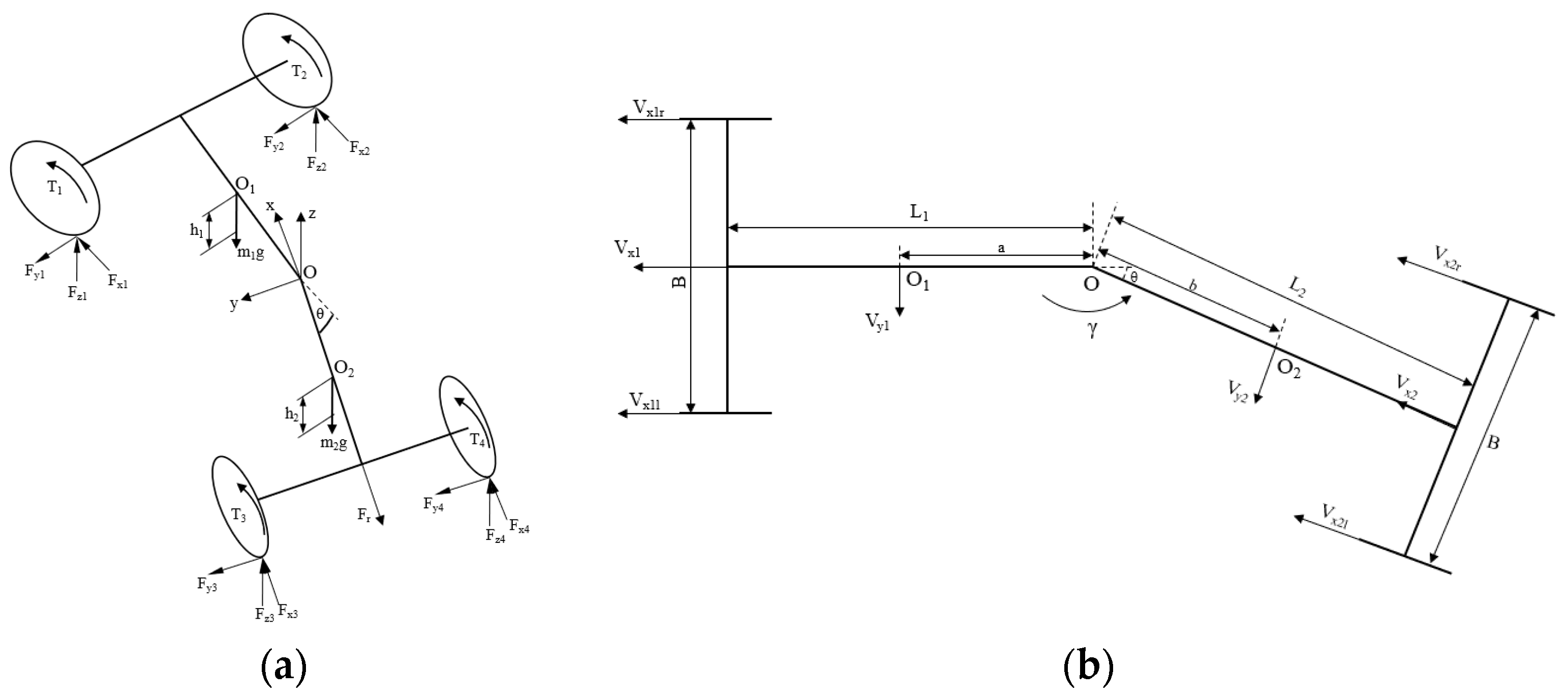
To simplify the analysis, the effects of pitch and roll are neglected. Figure 1 shows the simplified dynamic model of the articulated tractor, where Figure 1a presents the planar force analysis model and Figure 1b presents the kinematic model of the articulated steering system. In this study, the articulation angle θ is treated as a prescribed operating condition. Accordingly, the front and rear bodies are connected through the articulated joint with a fixed relative angle, and the yaw rates of the front and rear bodies are assumed to be equal to γ. In the XY plane, only three degrees of freedom are considered, namely longitudinal, lateral, and yaw motions. The above model is developed for control-oriented analysis under representative low-adhesion operating conditions. Therefore, several simplifying assumptions are adopted. In particular, the articulation angle is treated as a prescribed operating condition rather than a dynamic state variable. This assumption is reasonable for the present study, which focuses on steady or slowly varying steering maneuvers on low-adhesion surfaces. However, it may limit the applicability of the model under rapid steering maneuvers or highly complex mountainous terrains with strong pitch-roll coupling. This limitation is acknowledged and will be further addressed in future studies by incorporating articulation-angle dynamics and more complex terrain interactions.
Figure 1.
Simplified full-vehicle model of the articulated tractor: (a) planar force analysis model; (b) kinematic model of the articulated steering system. The arrows indicate the directions of the velocities and forces. In the figure, a and b denote the distances from the articulation point to the centers of mass of the front and rear bodies, respectively, and B denotes the wheel track.
In this study, the 7-DOF dynamic model consists of three planar body-motion degrees of freedom and four wheel rotational degrees of freedom. The state vector can be written as
where vx and vy denote the longitudinal and lateral velocities of the tractor body, γ denotes the yaw rate, and ω1, ω2, ω3, and ω4 denote the angular velocities of the front-left, front-right, rear-left, and rear-right wheels, respectively. It should be noted that the vertical-load equations are introduced to calculate the dynamic normal loads of the four wheels and do not constitute additional generalized coordinates. In addition, the slip ratio is not treated as an external input of the plant. Instead, it is calculated from the wheel angular velocities and the corresponding wheel-center longitudinal velocities, and then used as a feedback variable for the slip controller.
Based on the kinematic model shown in Figure 1b, the kinematic relationship between the front and rear bodies can be established. Given that the articulated tractor steers via an articulated mechanism, it can be divided into front and rear vehicle bodies. The kinematic parameters of the rear body can be expressed utilizing the kinematic parameters of the front body. The kinematic relationship between the front and rear bodies is as follows:
Based on the planar force analysis model shown in Figure 1a, the longitudinal, lateral, and yaw dynamic equations can be derived. The longitudinal dynamics equation, which reflects the traction–resistance balance, is expressed as:
The lateral dynamics equation, which reflects lateral force equilibrium during articulated steering, is expressed as:
The yaw dynamics equation, which reflects yaw moment balance of the articulated tractor, is expressed as:
The vertical dynamics equations, which are used to determine wheel normal-load transfer, are expressed as:
where m1 and m2 are the masses of the front and rear vehicle bodies (kg), respectively; vx1, vx2 are the longitudinal velocities of the front and rear vehicle bodies (m/s); vy1 and vy2 are the lateral velocities of the front and rear vehicle bodies (m/s); Fx is the tire longitudinal force (N); Fy is the tire lateral force (N); θ is the articulation angle (rad); γ is the yaw rate of the vehicle body (rad/s); and Fr is the traction resistance of the tractor (N); I1 and I2 are the moments of inertia of the front and rear vehicle bodies (kg·m2), respectively; L1 and L2 are the distances from the articulation point to the front and rear axles (m), respectively; and B is the wheel track (m); a and b are the distances from the articulation point to the centers of mass of the front and rear bodies, respectively (m). The subscripts 1, 2, 3, and 4 denote the front-left, front-right, rear-left, and rear-right wheels of the tractor, respectively.
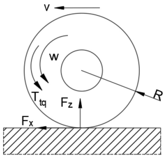
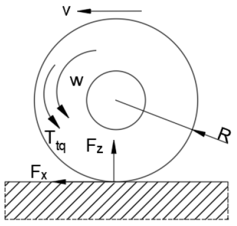
In addition to the planar body motion, the rotational dynamics of the four driving wheels must be considered to complete the 7-DOF formulation. The wheel rotational model describes the relationship among the motor torque, tire longitudinal force, and wheel angular acceleration, and provides the necessary rotational states for subsequent slip-ratio calculation and torque control. Figure 2 illustrates the wheel rotational dynamics model, from which the rotational dynamics equations for the four wheels can be derived.
Figure 2.
Wheel Rotational Dynamics Model. The arrows indicate the directions of the wheel rotational speed, vehicle velocity, and tire forces.
The rotational dynamics equations of the four wheels about their centers, which describe the balance among motor torque, longitudinal tire force, and wheel angular acceleration, are expressed as:
where J is the moment of inertia of the wheel (kg·m2); is the angular acceleration of the wheel (rad/s2); Ttqi is the driving torque of the wheel (N·m); i0 is the wheel reduction gear ratio; η is the transmission system efficiency; R is the wheel radius (m); f is the rolling resistance coefficient; and the subscript i denotes the front-left, front-right, rear-left, and rear-right wheels, respectively.
2.2. Tire Dynamics Model
In this study, the tire model is introduced for control-oriented dynamic analysis rather than high-fidelity tire characterization. Therefore, the selection of the tire model should balance physical representativeness and computational efficiency. Compared with more parameter-intensive tire models, such as the Magic Formula model, the Dugoff tire model requires fewer parameters and has a simpler mathematical structure, which makes it more suitable for repeated iterative simulation, controller development, and hardware-in-the-loop implementation. More importantly, the Dugoff model can still capture the essential nonlinear relationship among slip ratio, slip angle, tire forces, and road adhesion, which is sufficient for the anti-slip control and torque allocation objectives considered in this paper. Although more complex tire models may provide higher fitting accuracy under broader operating conditions, the Dugoff model offers a reasonable compromise between model fidelity and real-time applicability for the present control-oriented study. Its mathematical expression is as follows:
where Cx and Cy are the longitudinal and lateral cornering stiffness of the tire, respectively; S is the slip ratio; Φ is the tire nonlinearity characteristic parameter; Fy is the lateral force; μ is the road adhesion coefficient; τ is the velocity influence factor; and α is the tire slip angle.
The slip ratio for each of the four tires is calculated as follows:
where ω1, ω2, ω3 and ω4 are the angular velocities of the four wheels, respectively, which can be derived from Equation (6). vx1l, vx1r, vx2l, and vx2r are the longitudinal velocities of the four wheels, respectively, and can be expressed as follows:
The tire sideslip angle is defined as the angle between the actual traveling direction of the tire and the tire plane. Taking the leftward sideslip direction as positive, the sideslip angles of the four tires are given by:
in which the lateral velocity of each wheel center is expressed as follows:
2.3. Coupled Full-Vehicle Dynamic Model and Simulation Implementation
Based on the tractor-body dynamics, wheel rotational dynamics, and tire dynamic model presented above, a coupled full-vehicle dynamic model can be established. In this coupled model, the body-motion states determine the wheel-center velocities, the wheel rotational states provide the wheel angular velocities, the slip ratio is calculated from these two quantities, and the tire forces obtained from the Dugoff model are then fed back into both the body dynamics and wheel rotational dynamics. Through this bidirectional coupling, the complete dynamic interaction among vehicle motion, wheel rotation, slip evolution, and tire-road forces can be represented. The resulting coupled model is then implemented in MATLAB/Simulink as the basis for the subsequent controller design, simulation validation, and hardware-in-the-loop testing.
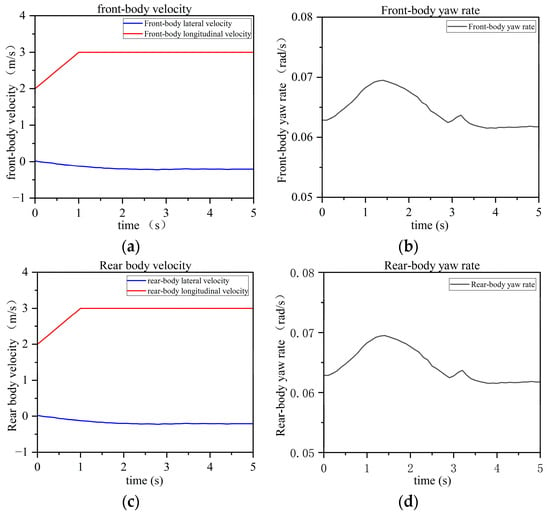
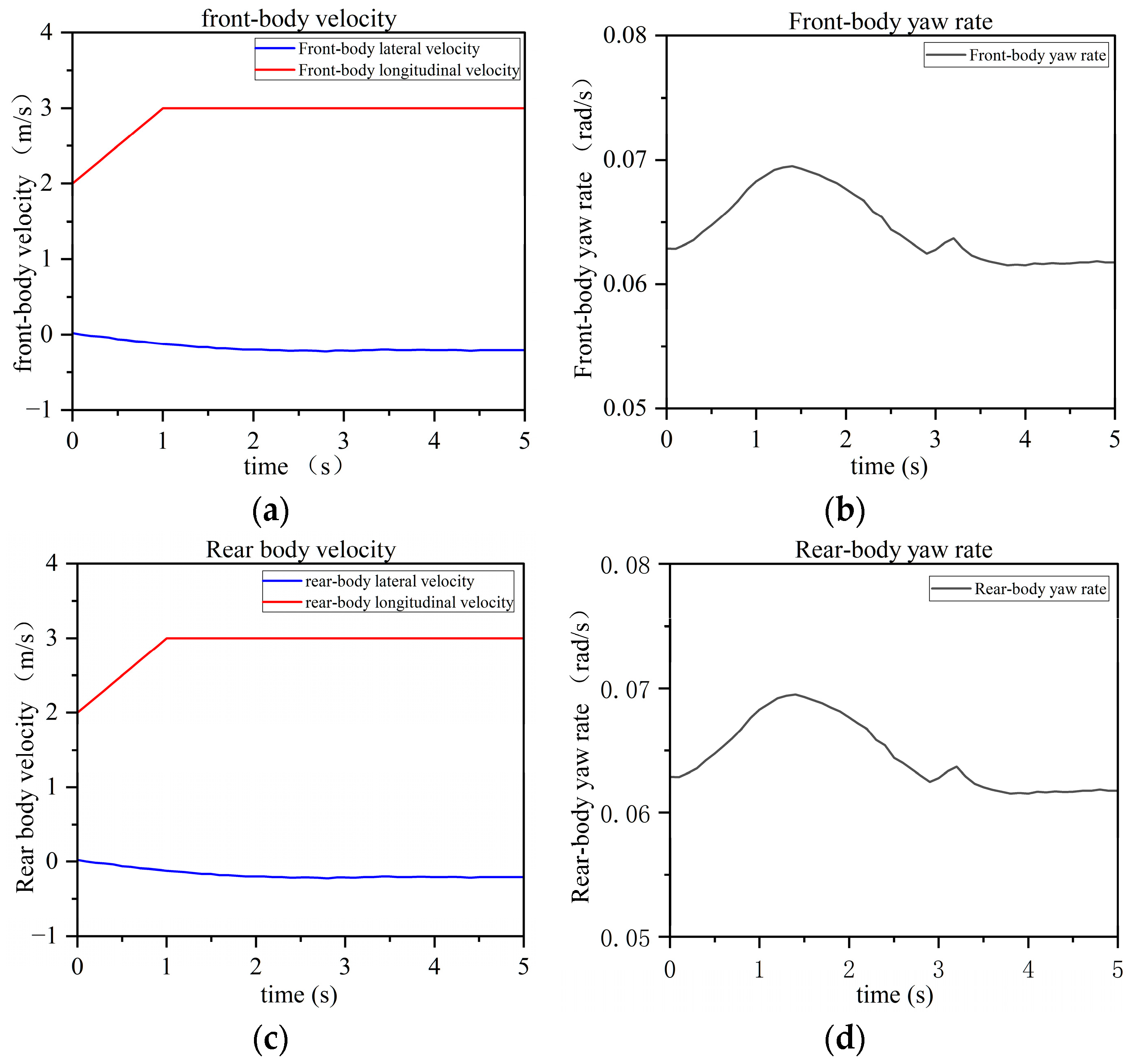
To validate the effectiveness of the seven-degree-of-freedom vehicle dynamics model established in the previous section, simulation-based verification of the tractor state parameters was carried out on the MATLAB/Simulink platform. The simulated velocities and yaw rates of the front and rear bodies are presented in Figure 3. The longitudinal velocities of both the front and rear bodies increase uniformly from 2 m/s to 3 m/s and then remain constant. During this process, the lateral velocities of the front and rear bodies are directed toward the outer wheels and are therefore negative. These values increase slightly during the acceleration phase and then gradually stabilize. Since the tractor is set to travel with an articulation angle of 10°, the yaw rates of the front and rear bodies remain identical. Both yaw rates increase gradually during the acceleration phase, then decrease and eventually stabilize after the vehicle enters the constant-speed phase. These results demonstrate that the articulated steering tractor dynamics model can effectively reproduce the tractor’s operating behavior, thereby providing a sound basis for subsequent research on slip ratio control algorithms and torque distribution strategies.
Figure 3.
Simulation validation of the vehicle dynamics model: (a) front-body velocity; (b) front-body yaw rate; (c) rear-body velocity; (d) rear-body yaw rate.
3. Design of Anti-Slip and Energy-Saving Control Strategy
When operating on complex field terrains, tractors are prone to wheel slip, which compromises driving stability. Addressing this issue, this paper proposes an anti-slip drive control strategy based on the optimal slip ratio. First, based on the previously established tractor vehicle dynamics model, the parameters required for simulation experiments are extracted to perform a structural description of the tractor. These physical parameters are then integrated into Simulink to develop a 7-DOF dynamics model, which comprises the 7-DOF vehicle model, wheel rotational dynamics model, tire dynamics model, real-time slip ratio calculation module, and slip ratio controller module. The error between the real-time slip ratio obtained from Simulink and the ideal slip ratio, along with its derivative, are utilized as the controller inputs. Fuzzy control is then applied with wheel torque as the output. This approach ensures that the tractor’s driving wheels operate within the optimal slip ratio range, thereby guaranteeing driving stability.
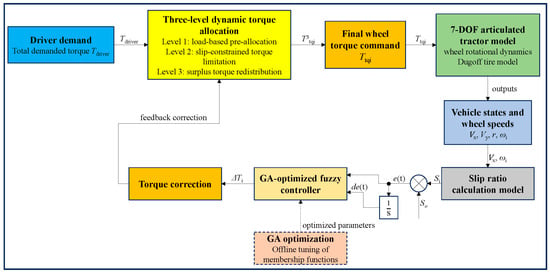
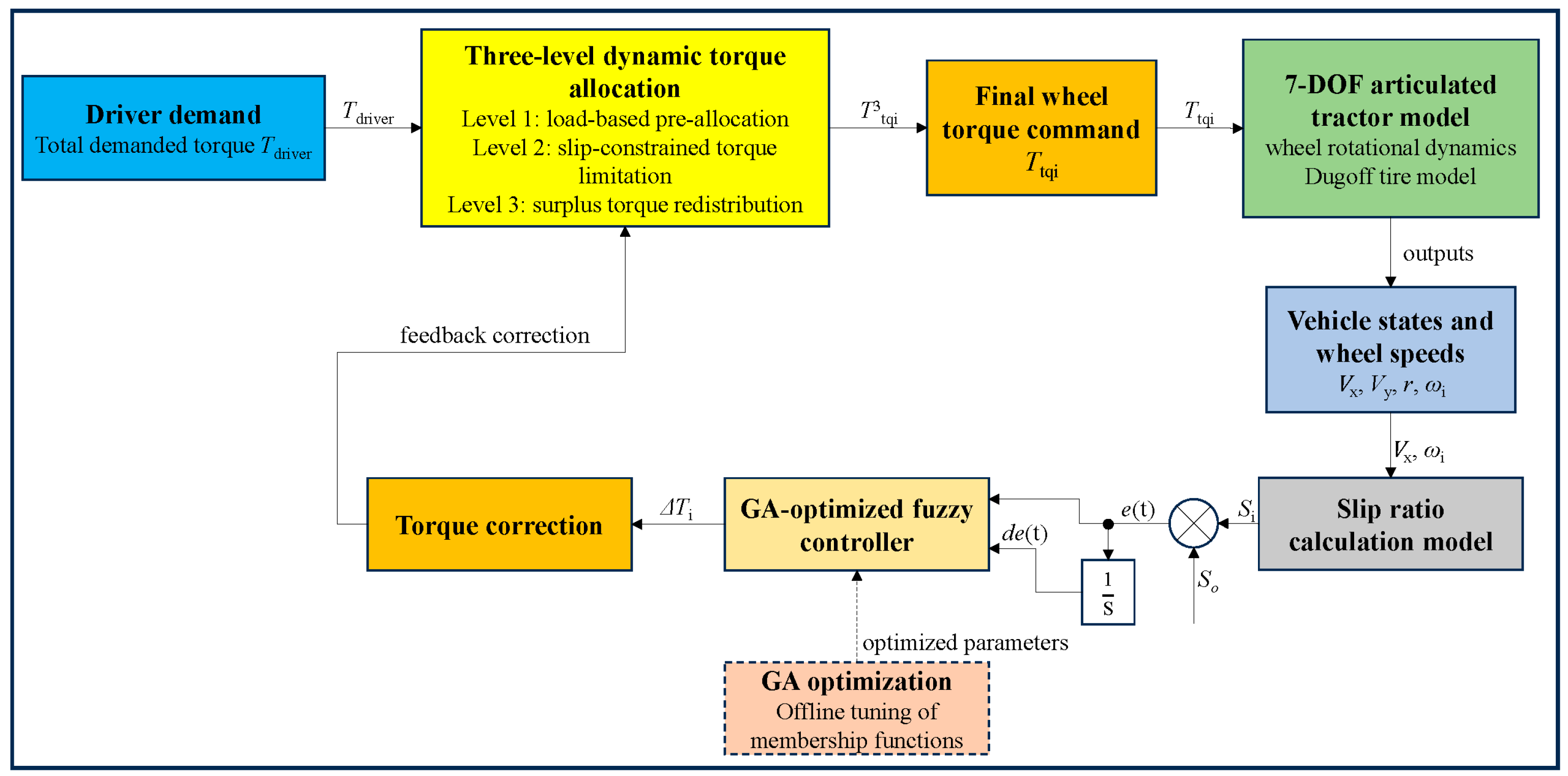
The main control principle of this study is illustrated in Figure 4.
Figure 4.
Integrated closed-loop control architecture of the proposed GA-fuzzy slip control and three-level dynamic torque allocation strategy. Blue blocks denote the input/state modules, yellow blocks denote the torque-allocation and correction modules, the green block denotes the 7-DOF tractor model, and the dashed orange block de-notes the offline GA optimization module.
Figure 4 illustrates the integrated closed-loop control architecture of the proposed anti-slip and energy-saving strategy for the articulated tractor. First, the driver demand determines the total required driving torque. Then, the three-level dynamic torque allocation module distributes the demanded torque to the four in-wheel motors according to wheel load conditions and slip-related constraints. The resulting wheel torques are applied to the 7-DOF articulated tractor model coupled with the wheel rotational dynamics and the Dugoff tire model. Based on the vehicle motion states and wheel angular velocities, the actual slip ratios of the four wheels are calculated in real time. The slip ratio error and its rate of change are then fed into the GA-optimized fuzzy controller to generate torque correction terms, which are fed back to the torque allocation module. In this way, an integrated closed-loop control framework combining slip regulation and torque allocation is established. It should be noted that the genetic algorithm is used for offline tuning of the fuzzy controller parameters, whereas the fuzzy inference and torque allocation are executed online during tractor operation.
3.1. Design of the Slip Ratio Controller
The operational state of a tractor changes in real-time during field operations, making it difficult to establish an accurate mathematical expression for quantitative analysis. In contrast, fuzzy control does not require an exact analytical model of the tractor’s operation; instead, it formulates fuzzy rules based on the practical insights and research experience of domain experts, offering strong robustness [31]. However, a standalone fuzzy controller cannot achieve optimal control in practical applications. This is especially true when operating on complex hilly and mountainous terrains, where rapidly changing soil conditions make it difficult for a fuzzy controller with fixed parameters to adapt. Therefore, this paper introduces a Genetic Algorithm (GA) to optimize the output torque membership functions of the fuzzy controller, achieving optimal slip ratio control under varying working conditions.
A genetic algorithm (GA) is a global optimization method inspired by the evolutionary process of natural selection. Through encoding, selection, crossover, and mutation, the GA iteratively searches for the optimal solution. A Genetic Algorithm can be defined as an 8-tuple, as expressed in Equation (13):
where C denotes the individual encoding method; E is the individual fitness evaluation function; P0 is the initial population; M represents the population size; ϕ is the selection operator; Γ is the crossover operator; Ψ is the mutation operator; and T is the termination criterion for the genetic operation.
During the selection stage, individuals are ranked according to their fitness values. The top 10 individuals are retained as elites, while the remaining individuals are selected probabilistically for the next generation. For the mutation operation, the mutation probability is determined by the fitness level: an individual with lower fitness has a lower probability of being selected for the next generation but a higher probability of undergoing mutation. Finally, after each genetic operation, individuals with higher fitness are as-signed to the subsequent generation until the iteration converges to the optimal solution.
Since this study utilizes the MATLAB/Simulink platform for simulation experiments, the fitness evaluation function is defined as:
where J is the objective function of the genetic algorithm, and eps denotes the floating-point relative accuracy in MATLAB. The purpose of incorporating eps is to prevent the denominator from becoming zero when the objective function value is zero, thereby avoiding undefined mathematical operations or non-convergence during the solution process.
3.2. Optimization of Fuzzy Logic Control via Genetic Algorithm
In the tractor anti-slip fuzzy control system, the accuracy of fuzzy inference highly depends on the distribution patterns of the output variable’s membership functions. Traditionally, membership functions are determined through trial-and-error and static tuning based on the engineering experience of domain experts. However, such subjective methods often fail to guarantee global optimal tracking of the slip ratio when confronted with the strong time-varying characteristics and spatial heterogeneity of soil physicochemical properties in complex hilly and mountainous terrains. To overcome this limitation, this paper introduces a Genetic Algorithm (GA), utilizing the tractor dynamics simulation model as the evaluation environment. The GA performs offline global optimization of the fuzzy controller’s membership functions to achieve adaptive matching across diverse soil adhesion characteristics.
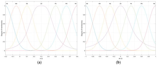
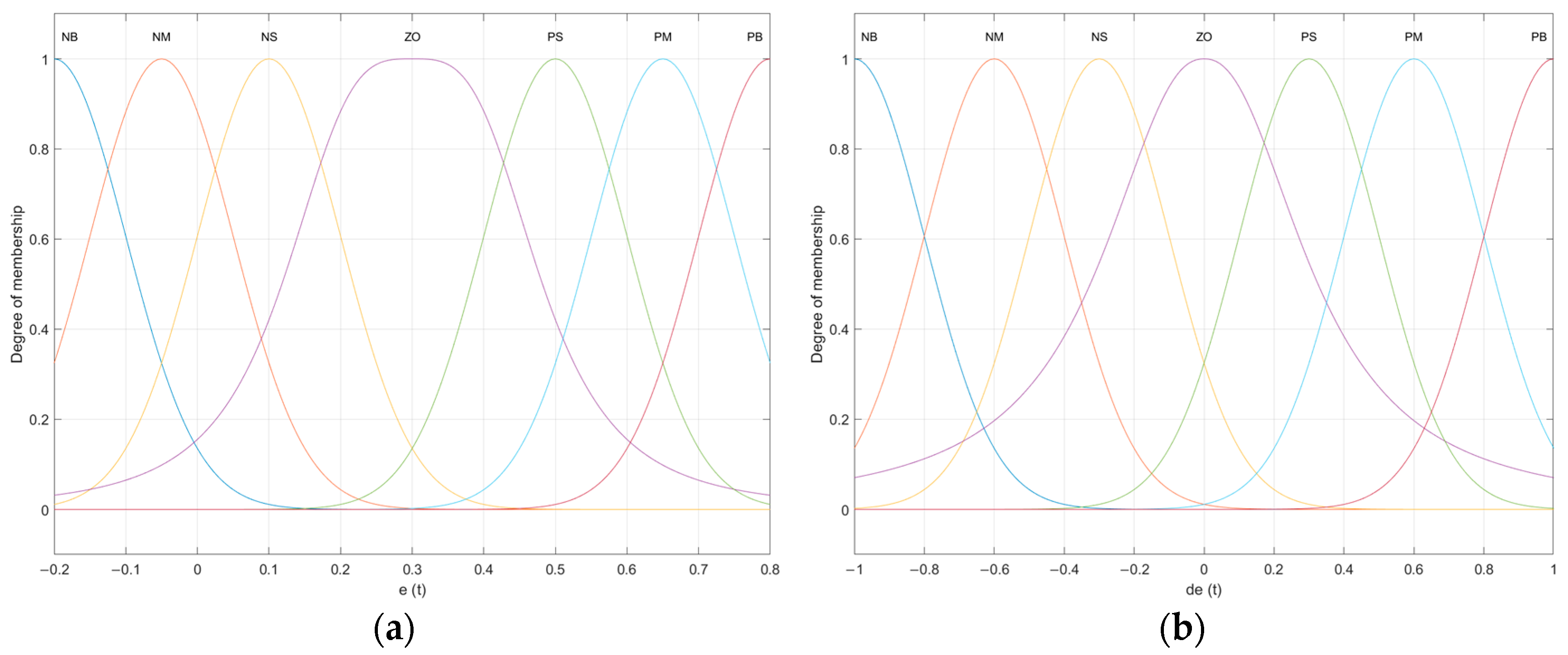
The input variables for the fuzzy controller are the error between the actual and optimal slip ratio, e (t), and its rate of change, de (t). The output variable is the torque of the four-wheel independent drive motors, Ttq. The basic universe of discourse for the slip ratio error is defined as [−0.2, 0.8], with the fuzzy input universe also set to [−0.2, 0.8] and a gain of 1. For the rate of change in the slip ratio error, the basic universe is [−1, 1], with the fuzzy input universe set to [−1, 1] and a gain of 1. The basic universe for the wheel torque is [−50, 50], with its fuzzy input universe set to [−1, 1] and a scaling gain of 25. The membership functions (MFs) for the input variables are selected as a combination of Gaussian and generalized bell-shaped functions, while triangular functions are employed for the output variable. Both input and output variables are partitioned into seven fuzzy linguistic levels: Negative Big (NB), Negative Medium (NM), Negative Small (NS), Zero (ZO), Positive Small (PS), Positive Medium (PM), and Positive Big (PB).
The selection of the fuzzy-controller structure is based on both the physical characteristics of slip control and the practical requirements of distributed-drive tractors. The slip-ratio error e (t) and its rate of change de (t) are adopted as the two input variables because they can jointly describe the instantaneous deviation from the target slip ratio and the dynamic evolution tendency of this deviation. The output variable is selected as the wheel torque command because the motor torque is the most direct and fastest controllable quantity for distributed-drive tractors. Seven linguistic levels are used for both the inputs and the output to provide a sufficient control resolution while avoiding an excessively complicated rule base. For the input variables, Gaussian and generalized bell-shaped membership functions are adopted to ensure smooth transitions among adjacent fuzzy regions and to reduce abrupt control changes. For the output variable, triangular membership functions are used because they are easy to parameterize and computationally efficient for GA-based optimization. The fuzzy rules are constructed according to the basic slip-control principle that a larger positive error and an increasing error trend should lead to a stronger corrective torque action, whereas a small error and a mild change trend should correspond to a weaker control action so as to avoid oscillations.
Since a standard triangular membership function is uniquely determined by three vertex parameters (a, b, c), direct encoding of these parameters often leads to overlap-ping disorder or loss of physical significance during genetic crossover and mutation. To prevent this, this paper does not encode (a, b, c) directly. Instead, the central vertex position b and the base width W of the triangle are extracted as the optimization variables. The remaining two vertices can then be de-rived using the following equations:
For the single target of slip ratio tracking, this study selects the Integral of Time-weighted Absolute Error (ITAE) as the comprehensive objective function J for system performance evaluation. The ITAE index exhibits a higher tolerance for initial errors in the system response but imposes an increasing heavy penalty on steady-state errors over time. This characteristic perfectly aligns with the dual requirements of anti-slip control systems for both rapid response and steady-state precision. The discretized mathematical model of the objective function J can be expressed as:
where tsim represents the total duration of a single simulation; Si(t) is the actual slip ratio output from the tractor dynamics model; and So(t) is the optimal slip ratio under the current soil conditions.
The membership functions of the input variables for the fuzzy controller are illustrated in Figure 5 [32].
Figure 5.
(a) Membership function of slip ratio error e; (b) Membership function of slip ratio error rate of change de.
According to fuzzy control theory, when the input variable error exhibits a trend of increasing or decreasing, the output variable must be adjusted accordingly to regulate these changes. Based on the research experience and expert knowledge in the field of vehicle control, a set of fuzzy control rules has been formulated. The corresponding rules are summarized in Table 1.
Table 1.
Fuzzy control rule table.
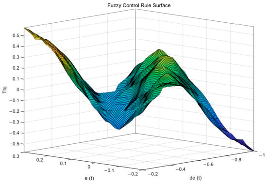
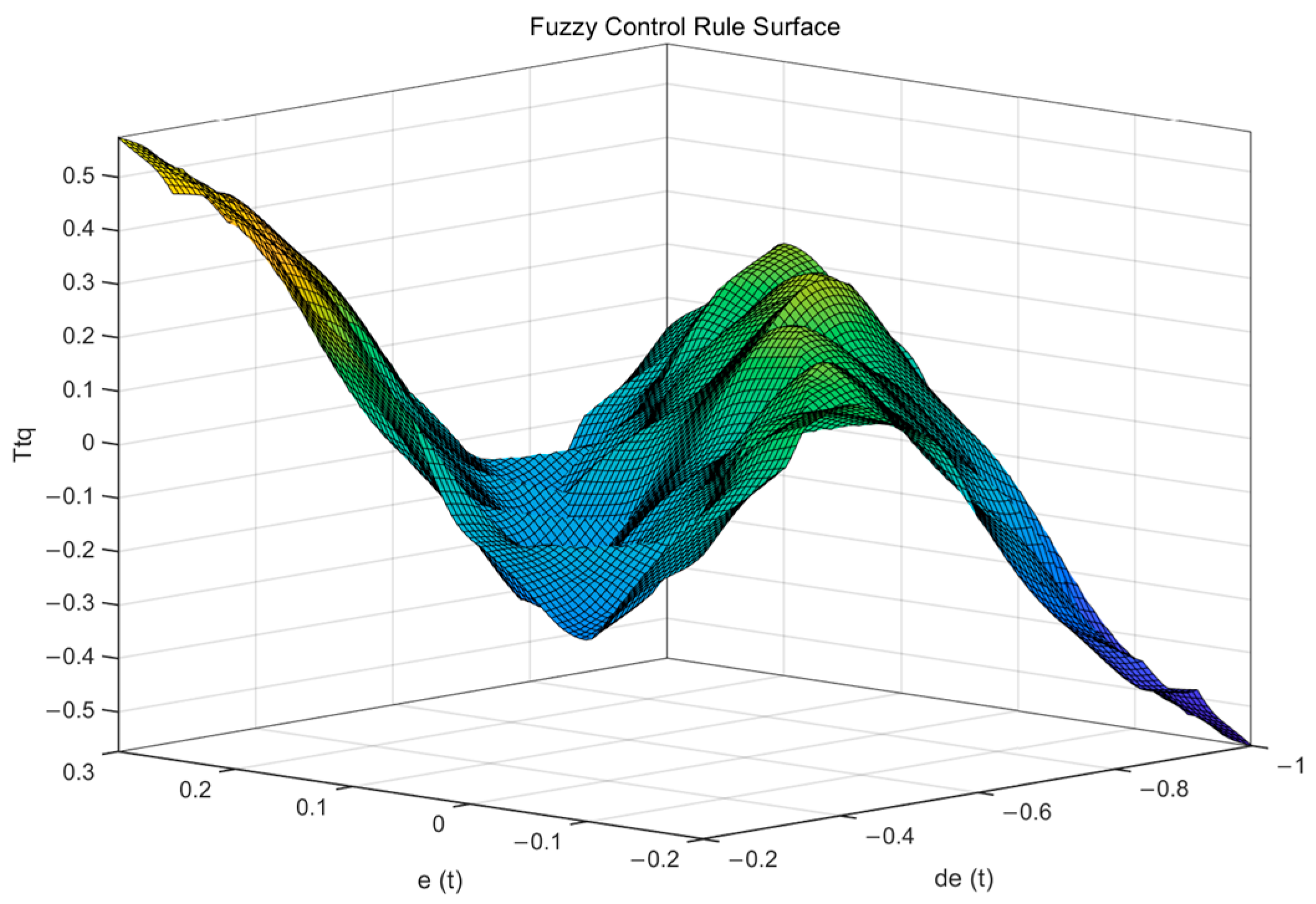
The corresponding fuzzy control rule surface is illustrated in Figure 6.
Figure 6.
Surface plot of the fuzzy control rules. The color gradient represents the magnitude of the control output.
3.3. Optimization Process of the Genetic Algorithm
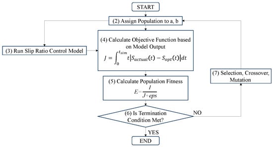
The optimization process relies on the joint iteration between the Genetic Algorithm (GA) main optimization program and the tractor dynamics simulation model. The specific execution flow is illustrated in Figure 7.
Figure 7.
Optimization process of the fuzzy controller based on Genetic Algorithm.
Figure 7 illustrates the flowchart of the fuzzy control optimization based on the Genetic Algorithm. The specific implementation steps are as follows:
Step (1): Initialize the population P0 and set the maximum number of evolutionary iterations.
Step (2): Assign the population individuals to the two control parameters, a and b, of the fuzzy controller.
Step (3): Execute the control model based on the current slip state of each wheel of the articulated vehicle and the target slip ratio.
Step (4): Calculate the objective function J according to the model output.
Step (5): Calculate the population fitness evaluation function E.
Step (6): Determine if the current iteration count exceeds the maximum limit. If satisfied, terminate the iteration and output the individual with the highest fitness obtained during the evolution as the optimal solution; otherwise, proceed to the next step.
Step (7): Perform the reproduction operation (ϕ) based on population fitness to filter out elite individuals, followed by crossover (Γ) and mutation (Ψ) operations to generate a new generation, then return to Step (2).
The initial parameters for the Genetic Algorithm are set as follows: population size is 40; number of iterations is 100; crossover probability is 0.8; and mutation probability is 0.1.
3.4. Design of the Dynamic Torque Allocation Strategy
Currently, most control strategies for tractor torque allocation determine the total required driving torque based on the driver’s accelerator pedal input, and then distribute it to each wheel’s drive motor according to a fixed ratio. However, under complex operating conditions, this rigid allocation strategy cannot dynamically adapt to the tractor’s working state. Consequently, it fails to achieve optimal driving performance and leads to energy waste. To address this, this paper proposes a three-level dynamic torque allocation energy-saving control strategy. This proposed strategy is comparatively analyzed against an equal torque allocation strategy, and its effectiveness is ultimately verified through simulation experiments.
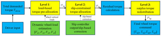
Figure 8 illustrates the working principle of the proposed three-level dynamic torque allocation strategy. First, the total demanded driving torque is obtained from the driver input and preliminarily distributed according to the real-time vertical loads of the four wheels. Then, the preliminary torque allocation is corrected and constrained by the slip-controller output to prevent excessive slip and motor over-torque. Finally, the residual torque released from the torque-limited wheels is redistributed to the wheels with remaining traction potential, thereby obtaining the final wheel torque command.
Figure 8.
Block diagram of the proposed three-level dynamic torque allocation strategy. Blue blocks denote the driver-input and final-command modules, yellow blocks denote the three torque-allocation levels, and green blocks denote the wheel-load estimation and slip-based correction modules.
The allocation strategy designed in this section utilizes the previously proposed anti-slip drive control strategy as its core to formulate an energy-saving optimization control strategy featuring a three-level dynamic allocation of driving torque. The specific details are as follows:
- (1)
- First-level allocation of driving torque based on four-wheel vertical load distribution
Based on the driver’s operation of the accelerator pedal, the total driving torque currently required by the vehicle is obtained, as shown in Equation (18):
where Tdriver is the total driving torque currently demanded by the vehicle; δ represents the percentage of the current effective accelerator pedal travel relative to the total effective travel; and Ttotal is the maximum total driving torque available to the vehicle when the accelerator pedal reaches 100% of its effective travel.
Based on the real-time dynamic loads of the wheels, the output torque allocated to the four motors is calculated as follows:
where T1tqi respectively denote the output torques allocated to the front-left, front-right, rear-left, and rear-right drive motors. The superscript ‘1’ indicates the primary (first-level) allocation of the driving torque.
- (2)
- Secondary driving torque allocation based on the tractor slip ratio controller
Once the vehicle enters the driving state, the slip ratio controller calculates the required control torques for the front-left, front-right, rear-left, and rear-right drive motors. In the actual driving process, since the output torque of the drive motors should not exceed the driver’s demanded operational input, a secondary allocation of the driving torque is performed based on the slip ratio control requirements and the results of the primary allocation:
where T2tqi respectively represent the output torques allocated to the front-left, front-right, rear-left, and rear-right drive motors. The superscript ‘2’ indicates the secondary (second-level) allocation of the driving torque, and Ttqi out denotes the output torque from each respective slip ratio controller. Simultaneously, this process serves as an amplitude limit for the torque outputted by the slip ratio controllers. Specifically, a saturation module is integrated into the controller block to prevent the motor output torque from exceeding its maximum capacity during sudden variations in the vehicle’s slip ratio.
- (3)
- Tertiary allocation for dynamic optimization of the driving torque
During the torque allocation process, the following three scenarios may occur:
Scenario a: The output torques of all four slip ratio controllers are greater than the values obtained from the primary allocation for the four drive motors. In this case, the following applies:
Scenario c: The output torques of some, but not all, of the four slip ratio controllers are greater than the primary allocation values of their respective drive motors. Specifically, for a certain portion of the drive motors, the torque demand from the slip ratio controller is less than the primary allocation value, causing the system to output the calculated torque from the slip ratio controller (due to slip prevention). For the remaining drive motors, the torque demand from the slip ratio controller exceeds the primary allocation value, resulting in the torque being capped at the primary allocation value. Consequently, some motors cannot fully utilize their allocated torque (due to slip limits), while others have their torque output artificially restricted (despite having greater traction potential).
To maximize the utilization of the driving torque in accordance with the driver’s accelerator pedal intention, enhance the vehicle’s driving performance, and increase torque utilization efficiency, the surplus torque allocated to the slip-limited motors undergoes a dynamic optimization adjustment. This surplus torque is reallocated to the remaining motors that have sufficient traction potential but are currently experiencing a drive torque deficit. This process constitutes the tertiary allocation of the driving torque, which is expressed as follows:
where Δmean is calculated as follows:
where n represents the number of drive motors satisfying ΔTi > 0, and eps is an infinitesimally small positive constant.
Consequently, the final output driving torques for the four drive motors (front-left, front-right, rear-left, and rear-right) are obtained through the comprehensive optimization control strategy based on the three-level dynamic torque allocation, which yields:
4. Simulation Experiments and Results Analysis
4.1. Simulation Validation of the Slip Ratio Control Strategy
To establish the physical model of the tractor, appropriate parameters must be configured within the Simulink platform to accurately replicate the tractor’s kinematic and dynamic behaviors during the simulation process. This study selects a specific model of Dong fanghong four-wheel independent drive electric tractor, specifically designed for hilly and mountainous terrains, as the research subject. Its main structural parameters and mass distribution are detailed in Table 2.
Table 2.
Main parameters of the tractor.
The main simulation conditions are summarized as follows. The tractor parameters are listed in Table 2. For the straight-line condition, the initial vehicle speed is set to 2 m/s, and the tractor enters the low-adhesion surface at t = 3 s, where the road adhesion coefficient is 0.3 and the target slip ratio is 0.2. For the steering condition, the vehicle speed is set to 2 m/s and the articulation steering angle is 10°, while the four wheels sequentially enter the low-adhesion surface from t = 1 s to t = 4 s. These settings are used consistently for the controller-performance comparison.
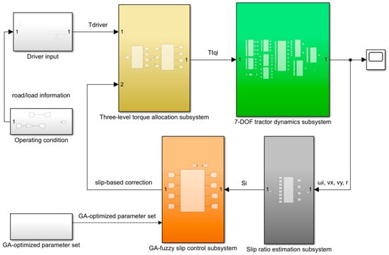
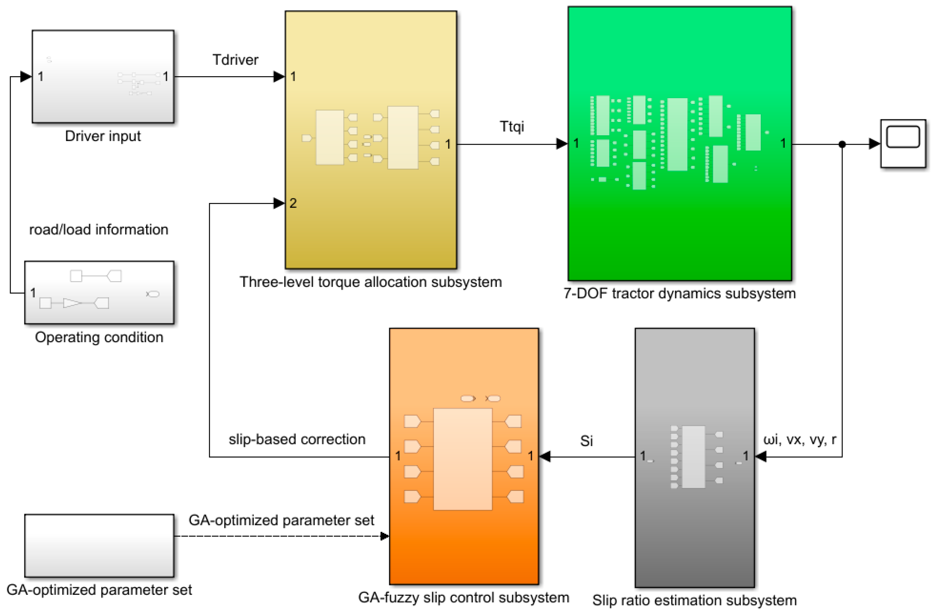
Based on Equations (2)–(26), the simulation model for the four-wheel in-dependent drive articulated steering electric tractor for hilly and mountainous terrains is constructed in MATLAB/Simulink. The top-level implementation of this simulation model is illustrated in Figure 9.
Figure 9.
Top-level MATLAB/Simulink implementation of the proposed control framework. The arrows indicate signal flow, numbers 1 and 2 denote Simulink input/output ports, white blocks denote input/operating-condition modules, yellow denotes the torque-allocation subsystem, green denotes the 7-DOF tractor-dynamics subsystem, orange denotes the GA-fuzzy slip-control subsystem, and gray denotes the slip-ratio-estimation subsystem.
To verify the control effectiveness of the proposed optimal slip ratio-based fuzzy anti-slip control strategy, a low-adhesion road surface is selected for simulation analysis. Since the tractor operates with an attached load, starting directly on a low-adhesion surface would cause excessive slipping of the drive wheels. Therefore, the simulation is designed such that the tractor travels at an initial speed of 2 m/s and enters the low-adhesion surface at the 3rd second.
- 1.
- Straight-line driving condition
The operating condition is set such that the tractor maintains straight-line driving at a speed of 2 m/s. At t = 3 s, it transitions from a high-adhesion road to a low-adhesion road, where the adhesion coefficient of the low-adhesion surface is set to 0.3. According to the adhesion coefficient-slip ratio curve, the optimal slip ratio for the tractor under this condition is 0.2.
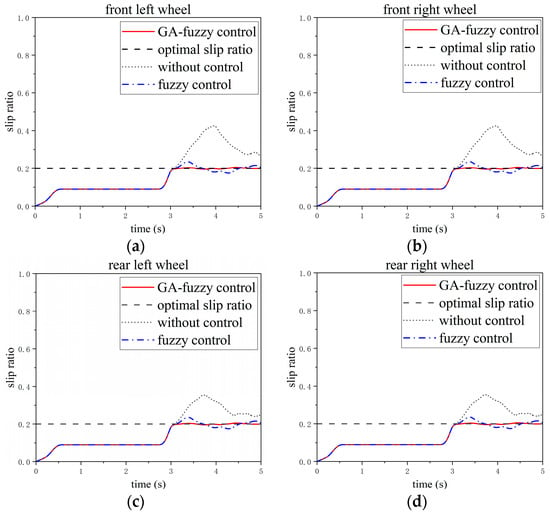
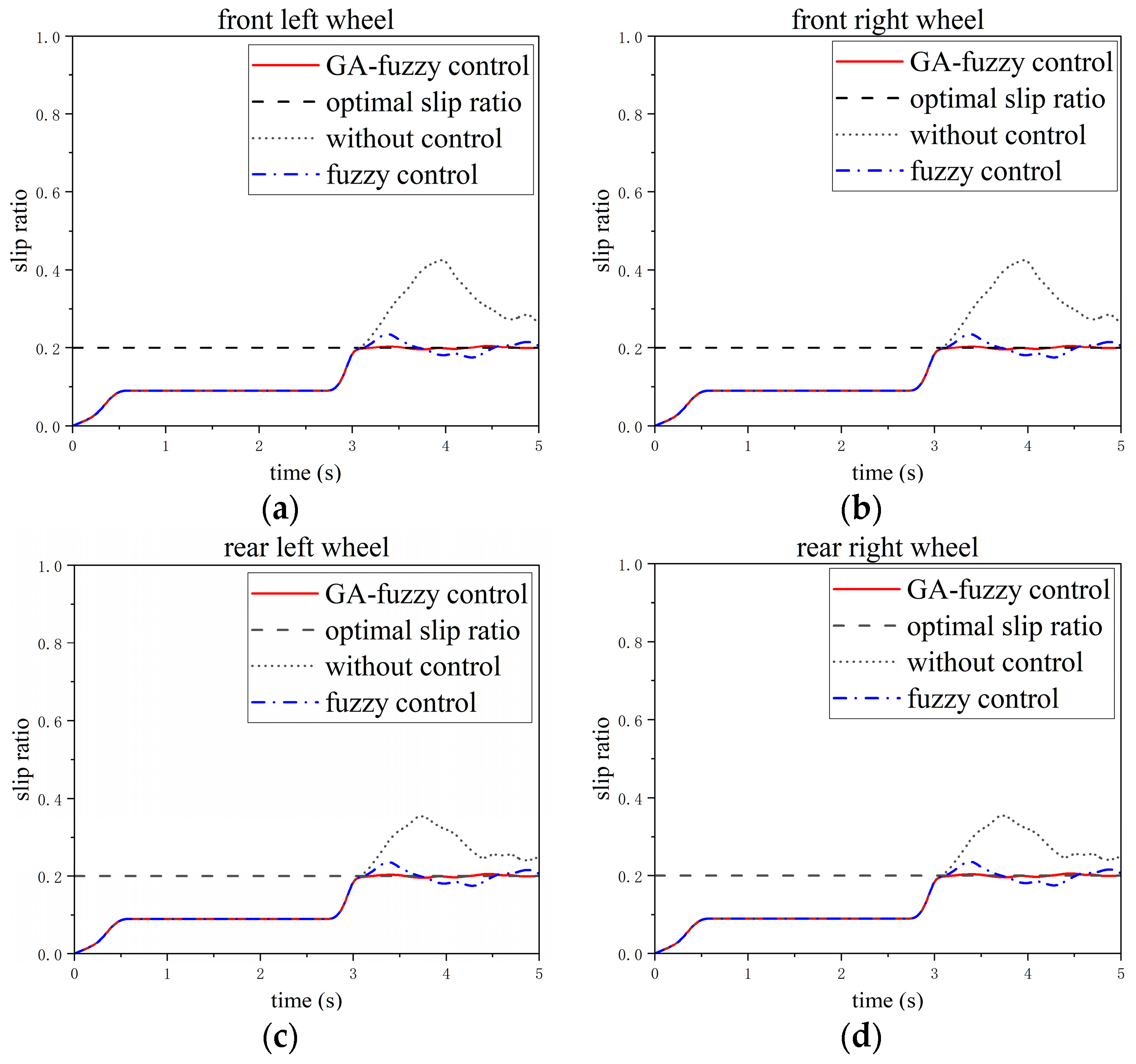
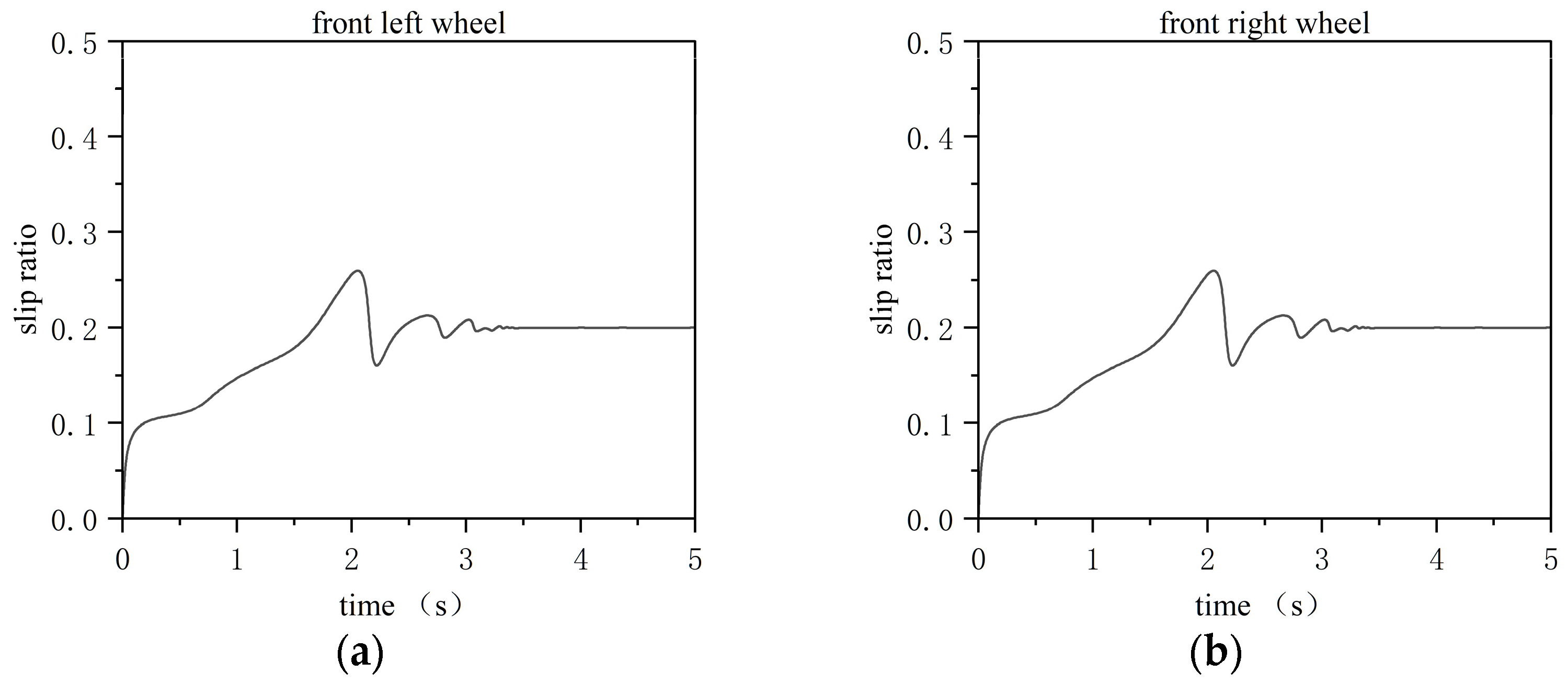
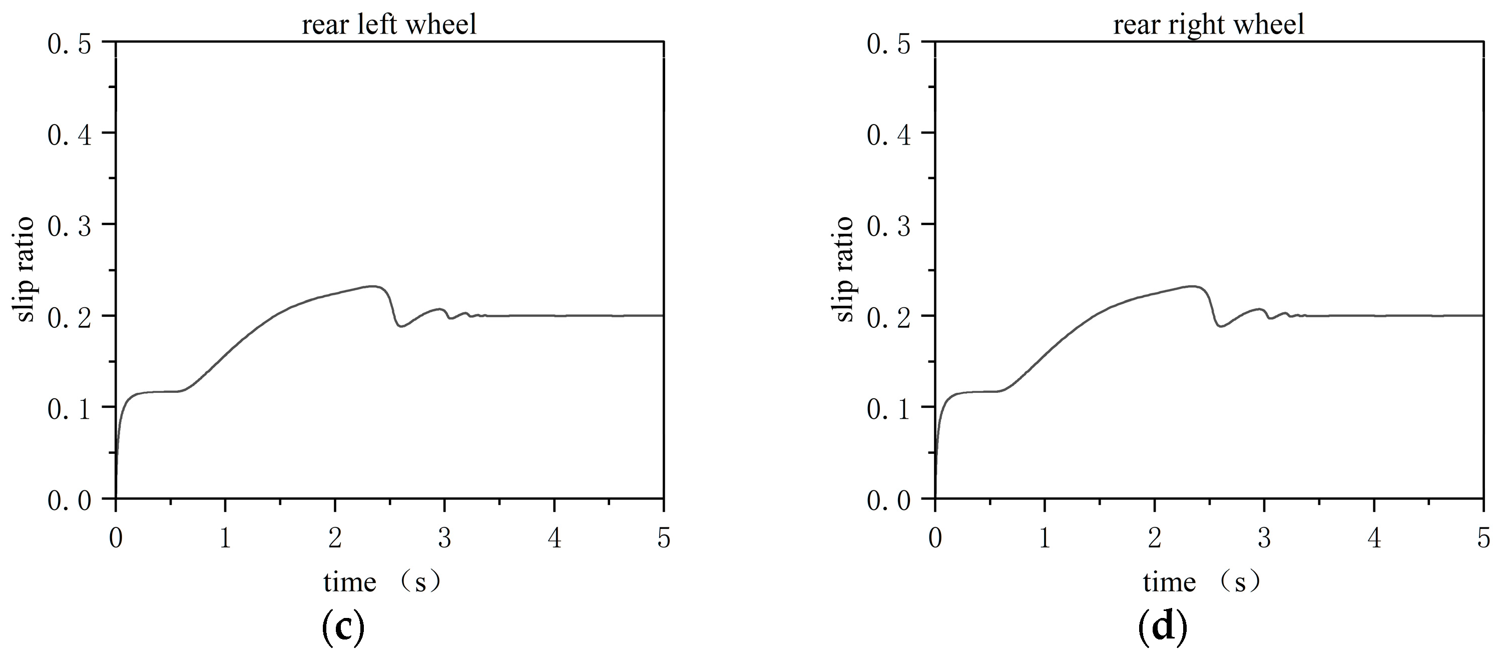
The simulation results are shown in Figure 10. When the tractor enters the low-adhesion surface at t = 3 s, the slip-ratio controller is activated. Using the error between the actual and target slip ratios, together with its rate of change, as the controller inputs, the GA-optimized fuzzy controller regulates the motor torque and rapidly drives the wheel slip ratio toward 0.2 with only small local fluctuations. The maximum tracking error is 0.0061, representing a reduction of 0.0322 compared with the conventional standalone fuzzy controller. In addition, the RMSE is reduced from 0.02716 to 0.00897, corresponding to a 66.98% improvement in tracking accuracy. These results confirm that the proposed GA-fuzzy controller provides substantially better slip-ratio tracking performance under the straight-line driving condition.
Figure 10.
Wheel slip ratio responses under straight line driving: (a) front left wheel; (b) front right wheel; (c) rear left wheel; (d) rear right wheel. The results compare the proposed GA-fuzzy controller with the conventional fuzzy controller.
- 2.
- Steering driving scenario
The operating condition is set such that the tractor travels at a speed of 2 m/s with a steering angle of 10°. Its front-left, front-right, rear-left, and rear-right wheels sequentially enter a low-adhesion surface from a high-adhesion surface at t = 1 s, 2 s, 3 s, and 4 s, respectively. The adhesion coefficient of the low-adhesion surface is set to 0.3, with a corresponding optimal slip ratio of 0.2.
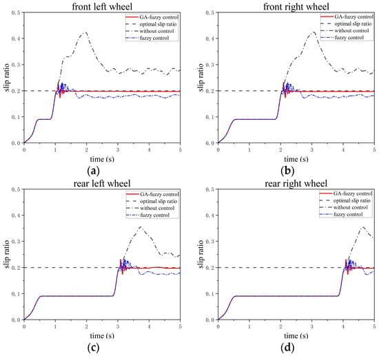
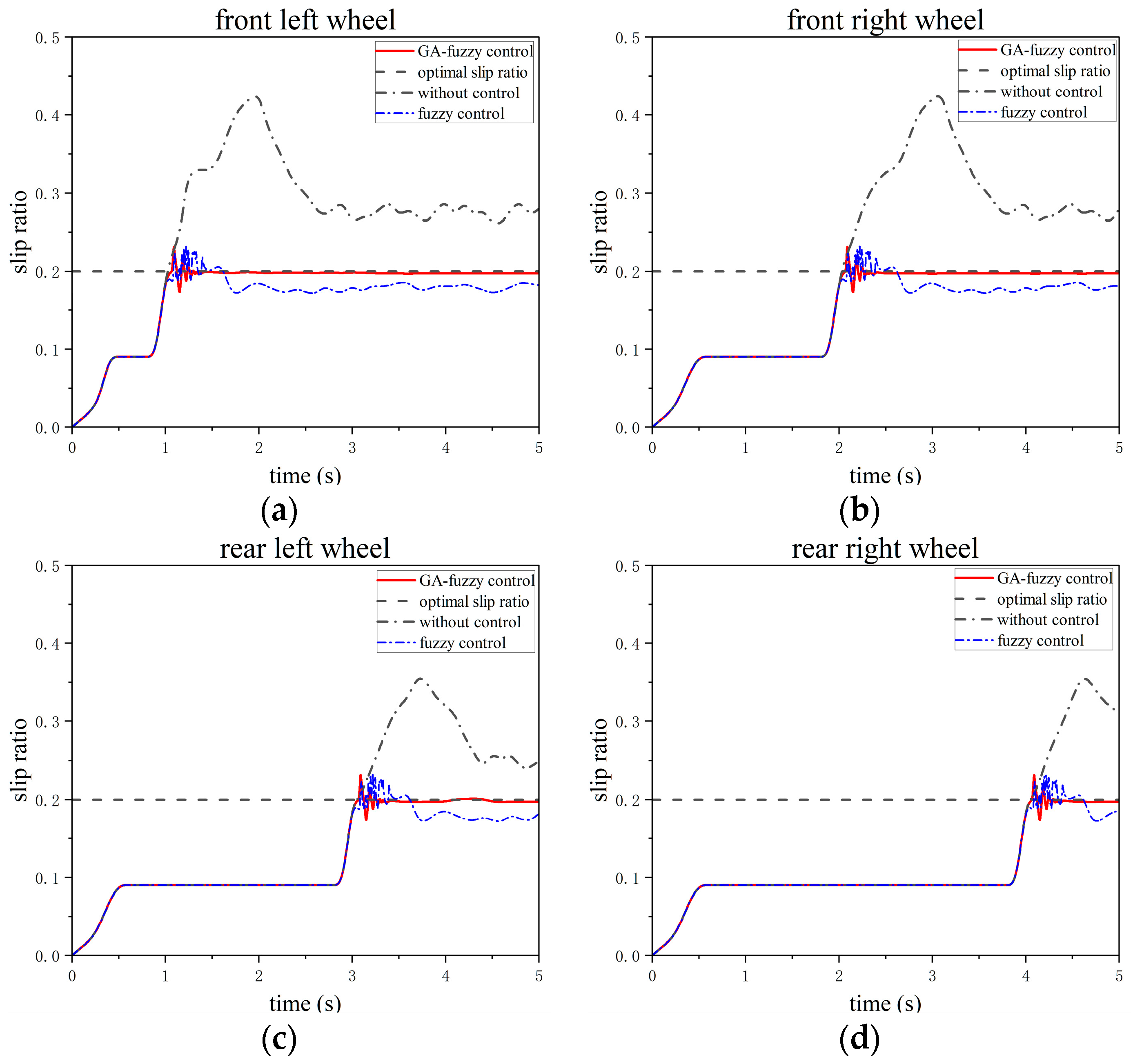
The simulation results are illustrated in Figure 11. As each wheel sequentially enters the low-adhesion surface, the sudden drop in the adhesion coefficient causes a rapid increase in the wheel slip ratio. However, the GA-fuzzy controller effectively regulates it to approximately 0.2 with minor local fluctuations. Specifically, the maximum tracking errors for the front-left, front-right, rear-left, and rear-right wheels are 0.0036, 0.0031, 0.0034, and 0.0032, respectively. Compared to the conventional fuzzy control, the slip ratio errors are reduced by 0.0274, 0.0278, 0.0284, and 0.0272, respectively, indicating a clear improvement in slip-ratio regulation for all four driving wheels. To further quantify the slip-ratio tracking performance under the steering condition, the root mean square error (RMSE) of the four driving wheels was calculated. For the proposed GA-fuzzy controller, the RMSE values of the four wheels were 0.00889, 0.00956, 0.01031, and 0.01137, respectively, with an average value of 0.01003. For the conventional standalone fuzzy controller, the corresponding RMSE values were 0.02072, 0.02076, 0.02084, and 0.02081, respectively, with an average value of 0.02079. Therefore, the proposed GA-fuzzy controller reduced the average RMSE by 51.75% under the steering condition. These results indicate that the proposed method can more effectively suppress wheel-slip fluctuations and improve the slip-ratio tracking accuracy of all four driving wheels during steering maneuvers.
Figure 11.
Wheel slip ratios responses under the steering driving scenario: (a) front left wheel; (b) front right wheel; (c) rear left wheel; (d) rear right wheel. The results compare the proposed GA-fuzzy controller with the conventional fuzzy controller.
Compared with the conventional standalone fuzzy controller, the proposed GA-fuzzy controller exhibits superior slip-ratio tracking performance under both straight-line and steering conditions, with RMSE reductions of 66.98% and 51.75%, respectively.
4.2. Simulation Validation of the Torque Allocation Strategy
To verify the superiority and effectiveness of the three-level dynamic torque allocation strategy, various torque allocation methods are simulated using MATLAB/Simulink. The following section provides a comparative analysis of the control performance between the equal torque allocation and the proposed three-level dynamic torque allocation when driving on a low-adhesion surface. The target slip ratio is set to 0.20.
First, the total driving torque currently demanded by the vehicle is obtained, and then the torque is distributed to the four wheel motors according to different allocation methods. The equal torque allocation, which distributes the torque evenly among the four wheels, is used as a baseline to compare with the dynamic torque allocation method based on slip ratio control designed in this paper.
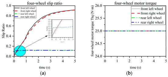
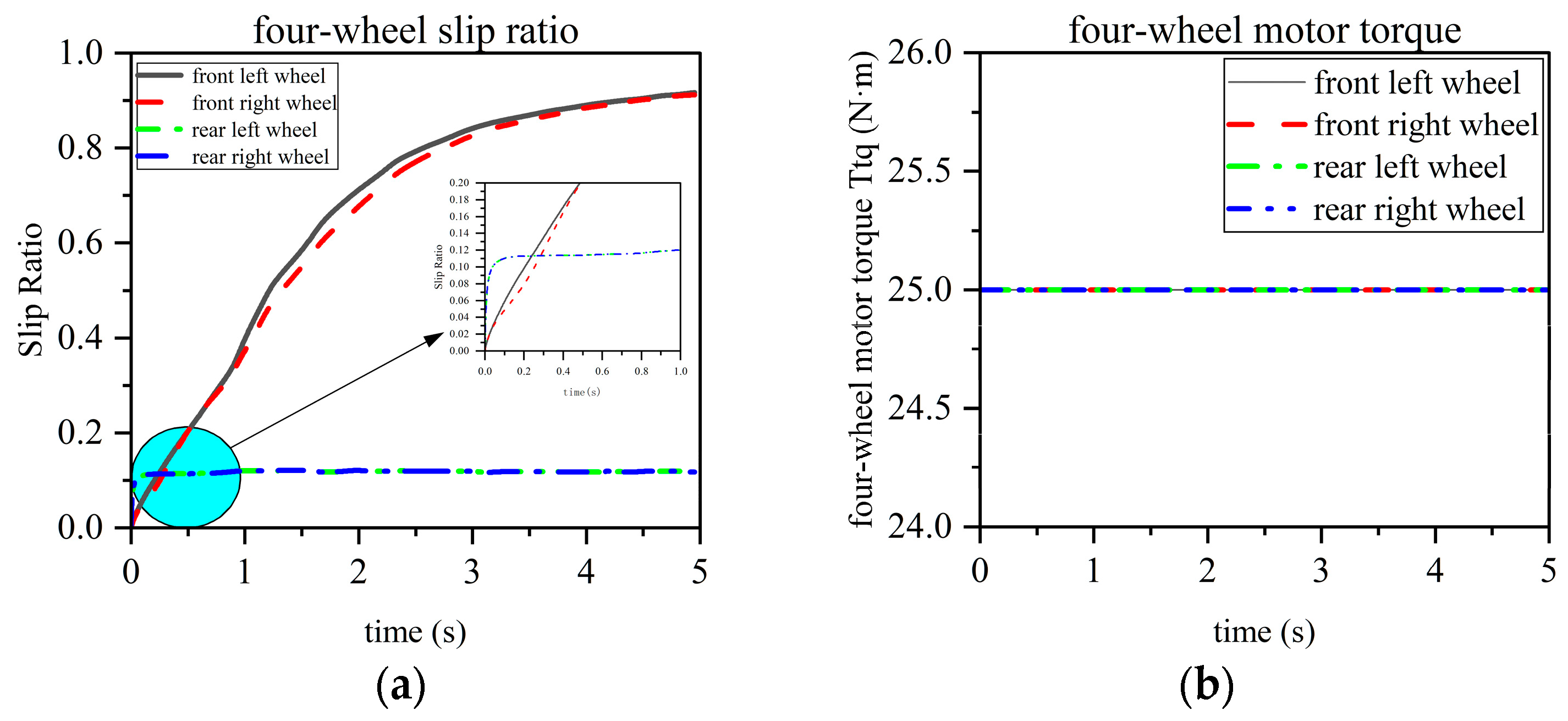
The operating condition is set to a low-adhesion surface, and the tractor travels with an articulated left steering angle of 10°. Figure 12 illustrates the slip ratios and torques under the equal torque allocation. Under this control strategy, the torque for all four wheels is fixed at 25 Nm. During tractor operation, the plowing resistance applied to the rear body increases the load on the rear wheels while decreasing the load on the front wheels. Consequently, the torque applied to the two front wheels exceeds the road adhesion limit, leading to excessive slipping; their slip ratios approach 1, indicating a near-spinning state. Conversely, the slip ratios of the two rear wheels fluctuate around 0.1. Although they do not experience excessive slipping, they fail to reach the target slip ratio (0.20), resulting in a suboptimal driving state and insufficient driving force.
Figure 12.
(a) Slip ratios under equal torque allocation; (b) motor torques under equal torque allocation.
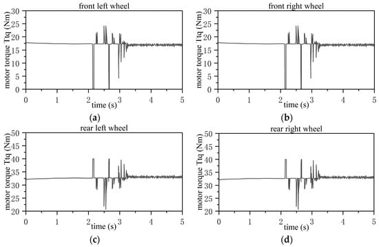
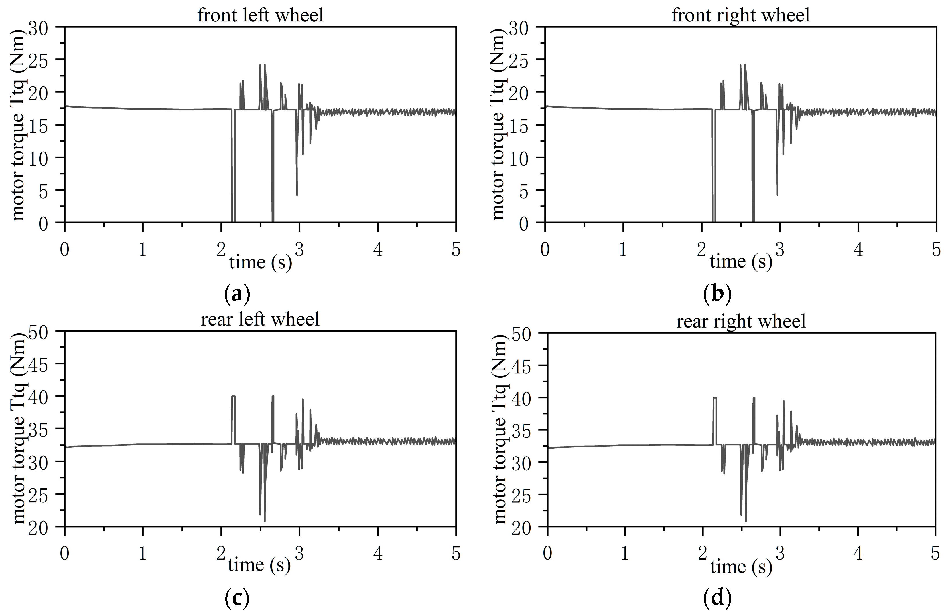
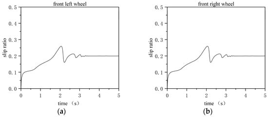
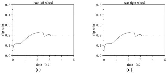
The operating condition is set to a low-adhesion surface, with the tractor traveling at an articulated left steering angle of 10°. Figure 13 displays the corresponding torque curves of the four wheel motors under the three-level dynamic torque allocation strategy, while Figure 14 illustrates the real-time slip ratio curves of the tractor’s four wheels.
Figure 13.
Torques of the four drive motors under dynamic torque allocation: (a) front left wheel; (b) front right wheel; (c) rear left wheel; (d) rear right wheel.
Figure 14.
Four-wheel real-time slip ratios under dynamic torque allocation: (a) front left wheel; (b) front right wheel; (c) rear left wheel; (d) rear right wheel.
As can be observed from the simulation results, during the 0 to 2 s period, the torque allocation is primarily executed based on the vertical load distribution. The torque remains stable, and the real-time slip ratios are largely kept within the effective range. However, as the vehicle continues to operate, the wheels begin to experience a certain degree of excessive slip. At this point, the slip ratio controller activates, gradually regulating the slip ratios back into the effective range and stabilizing them around the target slip ratio of 0.2. This indicates that the proposed three-level dynamic torque allocation strategy can effectively regulate slip under this operating condition.
Through the comparative analysis of the control performance between the equal torque allocation and the three-level dynamic torque allocation, it is evident that the equal torque allocation method results in either excessive wheel slip or insufficient driving force, failing to regulate the slip ratios within the effective range. In contrast, the proposed three-level dynamic torque allocation method not only restricts the slip ratios within a safe range but also actively maintains them at the target optimal value, thereby achieving maximum traction efficiency. This comparative analysis thoroughly verifies the effectiveness and superiority of the three-level dynamic torque allocation strategy.
To quantitatively evaluate the slip-regulation performance of the proposed torque allocation strategy, the slip-ratio tracking RMSE of the four driving wheels was calculated under the same operating condition. For the proposed three-level dynamic torque allocation strategy, the RMSE values of the four wheels were 0.022215, 0.022214, 0.020959, and 0.020971, respectively, with an average value of 0.02159. In contrast, for the equal torque allocation strategy, the RMSE values were 0.516107, 0.503067, 0.083061, and 0.083061, respectively, with an average value of 0.29632. Therefore, the proposed strategy reduced the average RMSE by 92.92% compared with the equal torque allocation strategy. In particular, the RMSE reduction at the front wheels was more pronounced, indicating that the proposed method can effectively suppress excessive front-wheel slip and improve slip-ratio regulation under uneven wheel-load and steering conditions.
4.3. Hardware-in-the-Loop Simulation Validation
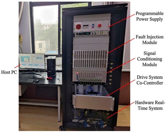
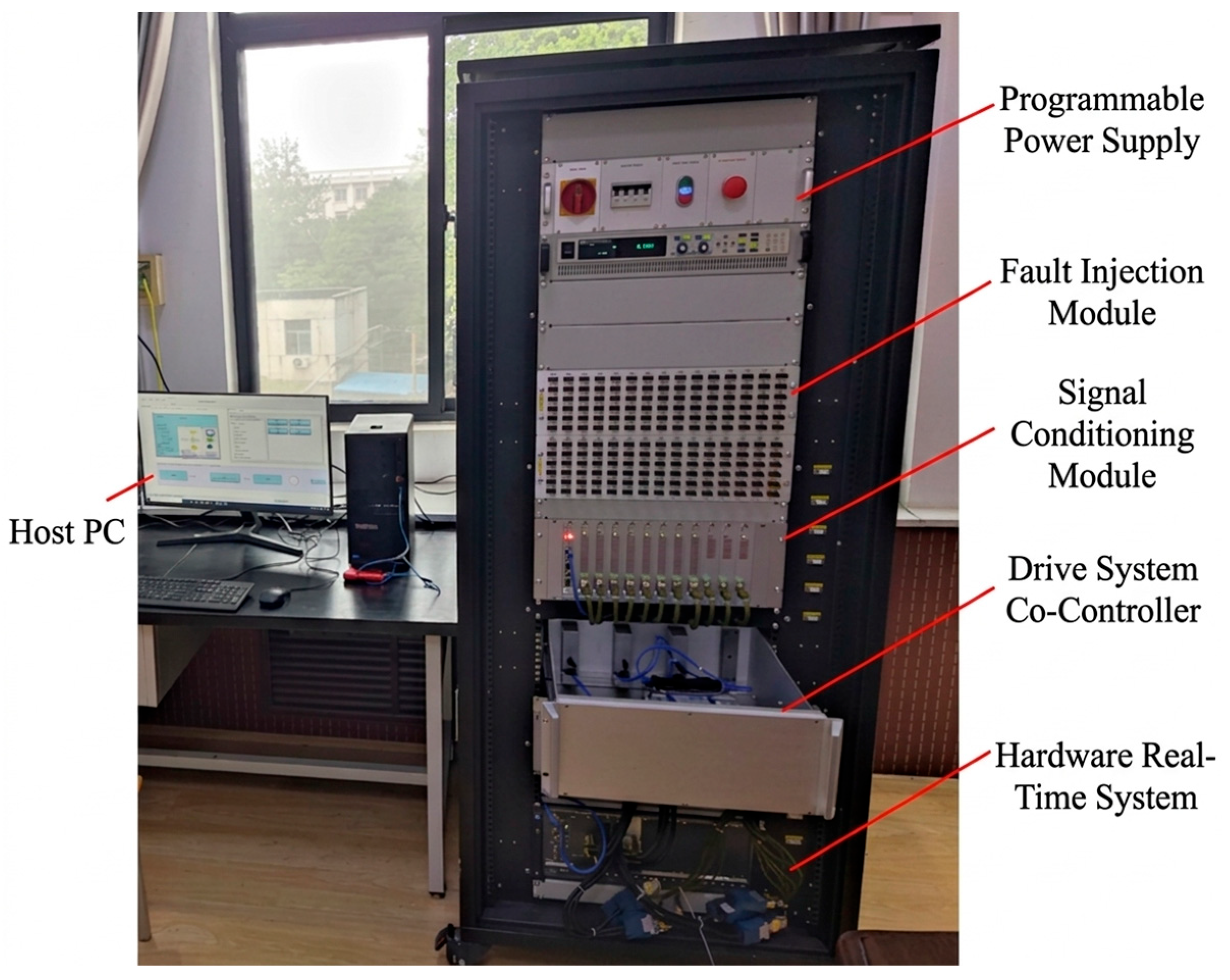
To further validate the real-time performance and effectiveness of the proposed drive control strategy, a Hardware-in-the-Loop (HIL) experimental platform is employed to test the dynamic torque allocation strategy.
The HIL experimental platform is built upon a PXI controller developed by National Instruments (NI, Austin, TX, USA). It primarily consists of an HIL test cabinet, a host PC, and the Controller Under Test (CUT). The HIL setup utilized in this study is illustrated in Figure 15. For clarity, the detailed hardware configuration of the HIL platform is summarized in Table 3. Specifically, the HIL test cabinet comprises a programmable power supply, a fault injection module, a signal conditioning module, a controller module, and a hardware real-time system. An NI PXIe-8880 controller serves as the real-time processor. The host PC (operating on Windows 10 64-bit, equipped with 32 GB RAM and a 3.2 GHz CPU) connects to the test cabinet via Ethernet and utilizes NI VeriStand (version 2023 Q4) software for test and experimental control. A Woodward SECM-70 module (Woodward, Fort Collins, CO, USA) is selected as the CUT. Analog input and output (I/O) operations are executed via an NI PXIe-6363 data acquisition card, while CAN signal communication with the HIL test cabinet is facilitated by an NI PXIe-8510 interface card. In the HIL implementation, the tractor dynamics model is executed on the real-time processor, whereas the proposed control algorithm is deployed in the controller-under-test through the configured I/O and CAN interfaces. This arrangement enables real-time closed-loop interaction between the virtual tractor plant and the physical control hardware.
Figure 15.
HIL experimental platform.
Table 3.
Hardware configuration of the HIL platform.
According to the test requirements, the HIL test environment is configured via the host PC, and the tractor dynamics model is loaded into the real-time processor. The control strategy is flashed into the Controller Under Test (CUT), which is then connected to the HIL test cabinet via a wiring harness. The test data is monitored and exported using the VeriStand software on the host PC.
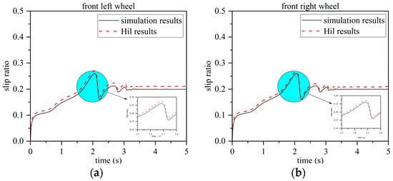
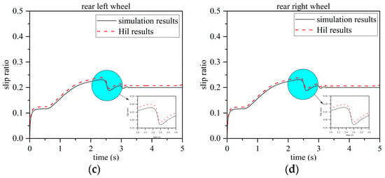
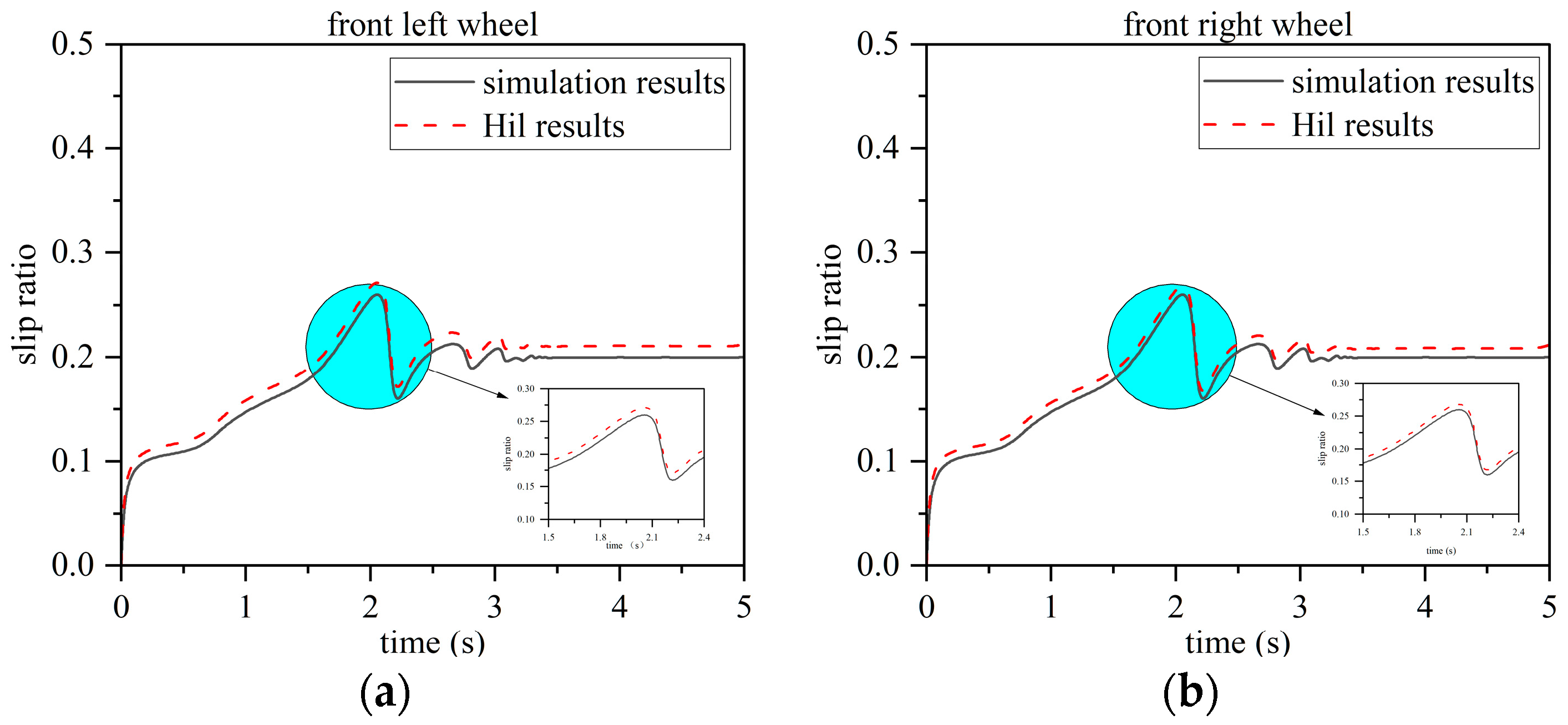
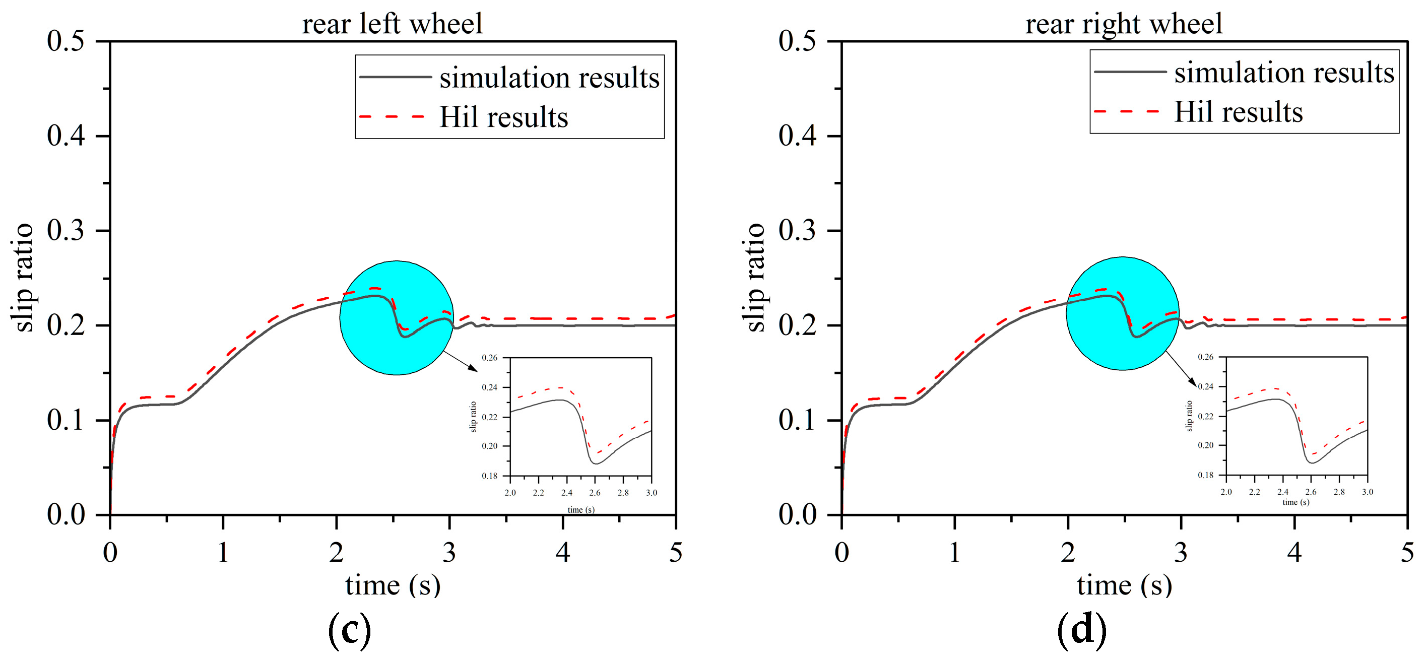
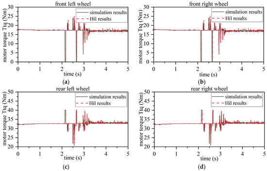
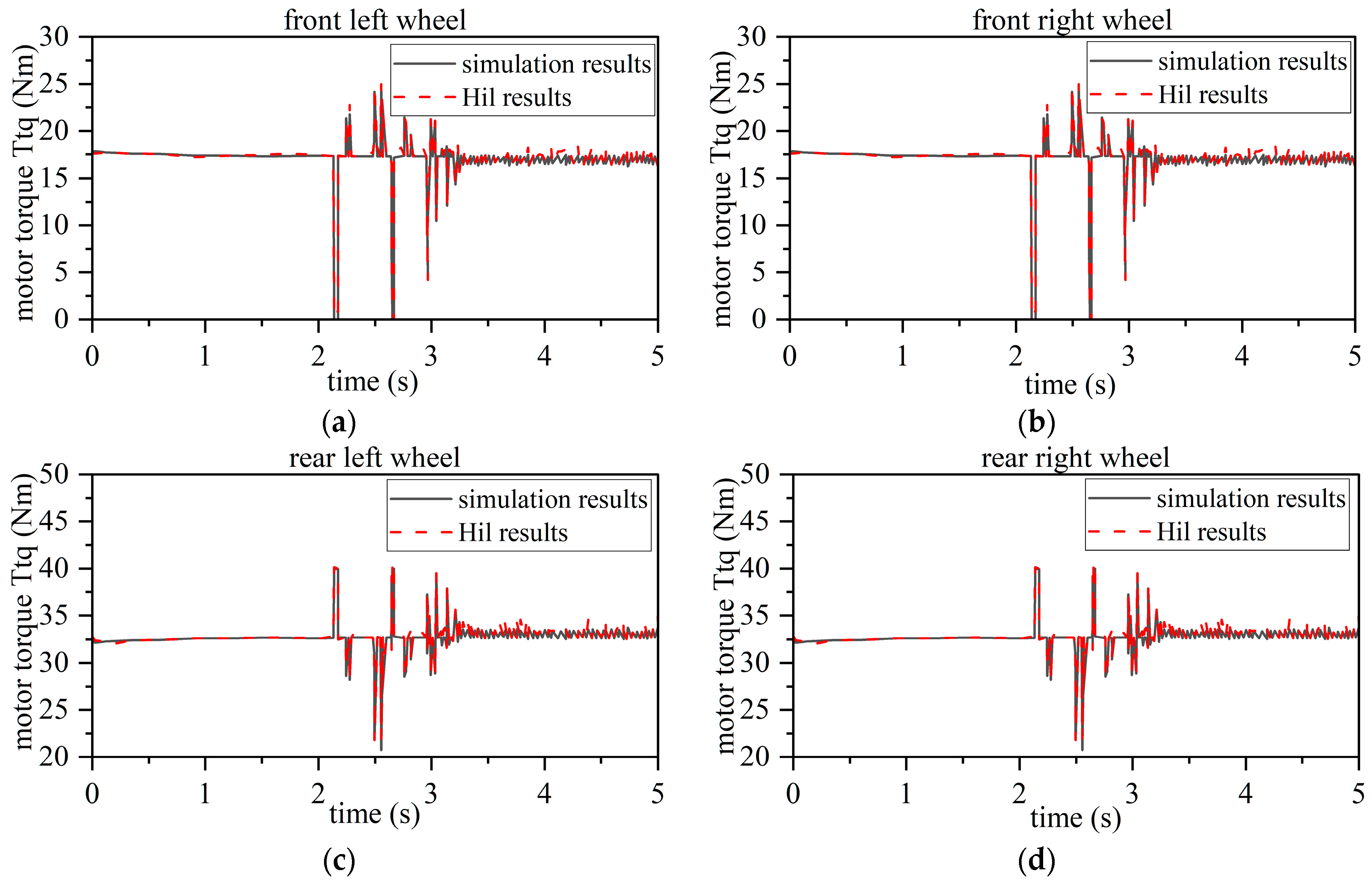
The HIL test step size is set to 0.05 s. The HIL results for the proposed drive-control strategy are presented in Figure 16 and Figure 17. As shown in Figure 16, the Simulink results for four-wheel slip-ratio control agree closely with the HIL results, with the RMSE of the slip ratio remaining below 0.008. Similarly, Figure 17 shows good agreement between the simulated and HIL motor-torque responses, with the torque RMSE remaining within 1.21 Nm. These results indicate that the proposed control framework can be executed with satisfactory real-time performance on actual hardware. Therefore, the HIL validation not only confirms the consistency of the simulation model, but also supports the practical deployment of the proposed strategy in future real-vehicle applications.
Figure 16.
Four-wheel slip ratio results from the HIL test: (a) front left wheel; (b) front right wheel; (c) rear left wheel; (d) rear right wheel.
Figure 17.
Four-wheel torque results from the HIL test: (a) front left wheel; (b) front right wheel; (c) rear left wheel; (d) rear right wheel.
4.4. Discussion
The results demonstrate that the proposed integrated control framework can effectively coordinate slip-ratio regulation and wheel-torque distribution for articulated tractors operating on low-adhesion surfaces. Under both straight-line and steering conditions, the GA-fuzzy controller achieves lower RMSE values than the conventional standalone fuzzy controller, indicating improved slip-ratio tracking accuracy and reduced local slip fluctuations. The main originality of this study lies in integrating GA-optimized slip control with a three-level dynamic torque allocation strategy into a unified framework specifically for four-wheel-drive articulated tractors.
The controller also exhibits different response characteristics under different operating conditions. Under the straight-line condition, the wheel responses remain relatively symmetric, resulting in faster convergence and smaller fluctuations. Under the steering condition, the responses become more asymmetric because the four wheels encounter the low-adhesion surface sequentially and experience different wheel-load and adhesion-utilization conditions. Even so, the proposed method maintains stable slip-ratio regulation for all four wheels, indicating that the framework is applicable to both symmetric and asymmetric low-adhesion scenarios. In the torque-allocation validation, the proposed three-level strategy significantly outperforms the equal torque allocation strategy, especially at the front wheels, because it can account for wheel-load variation, slip-related torque limitation, and surplus-torque redistribution.
The HIL results further enhance the engineering significance of the study. In addition to confirming the consistency of the simulation results, they show that the proposed algorithm can be executed in real time on an actual hardware platform. Compared with PID-based control, the proposed method is more suitable for strongly nonlinear and time-varying slip dynamics. Compared with sliding-mode or MPC-based methods, it offers smoother torque regulation and a lower computational burden, which is advantageous for real-time implementation in the present HIL-oriented architecture.
Nevertheless, several limitations remain. The current model adopts simplified assumptions, including a prescribed articulation angle and the neglect of more complex pitch-roll coupling. In addition, direct electrical-energy quantification and systematic robustness analysis under parameter perturbations have not yet been conducted. The present study also focuses on representative low-adhesion operating conditions rather than a wider range of soil types and parameter-varying scenarios. These issues will be addressed in future work through more comprehensive robustness analysis, extended multi-condition validation, and real-vehicle testing.
5. Conclusions
This paper proposes an integrated anti-slip and energy-saving-oriented control framework for a four-wheel independent drive articulated steering tractor based on the optimal slip ratio. The proposed framework combines a 7-DOF control-oriented dynamic model, a GA-optimized fuzzy slip-ratio controller, and a three-level dynamic torque allocation strategy, thereby providing a unified solution for coordinated slip suppression and torque distribution under low-adhesion operating conditions. This integrated architecture constitutes the main originality of the study relative to existing approaches that address slip control or torque allocation separately.
The simulation results demonstrate that the proposed method significantly improves slip-ratio tracking performance compared with the conventional standalone fuzzy controller. Under the straight-line driving condition, the RMSE is reduced from 0.02716 to 0.00897, while under the steering condition, the average RMSE of the four wheels is reduced from 0.02079 to 0.01003. For the torque-allocation validation, the average four-wheel RMSE is reduced from 0.29632 under equal torque allocation to 0.02159 under the proposed three-level dynamic torque allocation strategy. These results indicate that the proposed framework can effectively maintain the slip ratio near the target value, suppress excessive slip, and improve traction utilization in articulated tractors. In addition, the HIL results further confirm the real-time feasibility of the proposed method on an actual hardware platform.
Nevertheless, several limitations remain in the present study. The current model adopts simplified assumptions, such as a prescribed articulation angle, and does not yet consider more complex terrain coupling or direct electrical-energy evaluation. In addition, systematic comparisons with PID-, sliding-mode-, and MPC-based control strategies are still lacking. These issues will be addressed in future work through more comprehensive control comparisons, extended operating-condition validation, and real-vehicle implementation studies.
Author Contributions
Conceptualization, L.X. and C.T.; methodology, S.Z. and X.L.; software, C.T., J.W. and Y.L.; validation, L.X., C.T. and S.Z.; formal analysis, Y.W. and X.L.; investigation, S.Z. and Y.W.; resources, L.X.; data curation, Y.L. and S.Z.; writing—original draft preparation, L.X. and C.T.; writing—review and editing, L.X. and C.T.; visualization, L.X. and S.Z.; supervision, X.L.; project administration, L.X.; funding acquisition, S.Z. All authors have read and agreed to the published version of the manuscript.
Funding
This research was funded by National Natural Science Foundation of China (No. 52572495); National Key Research and Development Program of China (No. 2022YFD2001203); Open Fund of the State Key Laboratory of Intelligent Agricultural Power Equipment (No. SKLIAPE202508); Youth Program of the Natural Science Foundation of Henan Province (No. 252300420515); Key Scientific Research Project of Colleges and Universities in Henan Province (No. 25B460001); Zhongyuan Science and Technology Innovation Leading Talent Support Program (No. 244200510043); Science and Technology Innovation Team Support Program for Colleges and Universities in Henan Province (No. 24IRTSTHN029).
Data Availability Statement
The datasets presented in this article are not readily available because the data are part of an ongoing study.
Conflicts of Interest
The authors declare no conflicts of interest.
References
- Zhao, S.; Li, X.; Yan, X.; Zhang, J.; Wu, Y.; Xu, L. Review on key technologies of new power transmission systems for tractors. Trans. Chin. Soc. Agric. Mach. 2025, 56, 24–40. [Google Scholar]
- Luo, X. Thoughts on the development of agricultural mechanization in hilly and mountainous areas. Agric. Mach. Technol. Ext. 2011, 2, 17–20. [Google Scholar]
- Sun, J.; Liu, Z.; Yang, F.; Sun, Q.; Liu, Q.; Luo, P. Review on agricultural equipment and key technologies for slope operations in hilly and mountainous areas. Trans. Chin. Soc. Agric. Mach. 2023, 54, 1–18. [Google Scholar]
- Liu, Z. Research on Modeling and Measurement Methods of Tire Steady-State Rolling Resistance. Master’s Thesis, Changchun University of Technology, Changchun, China, 2025. [Google Scholar]
- Moinfar, A.; Shahgholi, G.; Gilandeh, Y.A.; Kaveh, M.; Szymanek, M. Investigating the effect of the tractor driving system type on soil compaction using different methods of ANN, ANFIS and step wise regression. Soil Tillage Res. 2022, 222, 105444. [Google Scholar] [CrossRef] [Scilit]
- Li, H. Research on the value and development of agricultural mechanization in the rural revitalization strategy. South. Agric. Mach. 2023, 54, 36–40. [Google Scholar]
- Liu, M.; Lei, S.; Zhao, J.; Meng, Z.; Zhao, C.; Xu, L. Review on the development history and research status of electric tractors. Trans. Chin. Soc. Agric. Mach. 2022, 53, 348–364. [Google Scholar]
- Xie, B.; Luo, Z.; Song, Z.; Wen, C.; Zhang, S.; Mao, E. Review on modeling methods and testing technologies of tire-soil interaction for off-road vehicles. Trans. Chin. Soc. Agric. Eng. 2022, 38, 51–63. [Google Scholar]
- Martelli, M.; Chiarabelli, D.; Gessi, S.; Marani, P.; Mucchi, E.; Polastri, M. Comprehensive lumped parameter and multibody approach for the dynamic simulation of agricultural tractors with tyre–soil interaction. IET Cyber-Syst. Robot. 2023, 5, e12092. [Google Scholar] [CrossRef] [Scilit]
- Yang, Y.J.; Jang, M.K.; Nam, J.S. Dynamic simulation model of miniature tracked forestry tractor for overturning and rollover safety evaluation. Agriculture 2024, 14, 1991. [Google Scholar] [CrossRef] [Scilit]
- Bi, S.; Han, Y. Real-time estimation method for tire dynamics parameters of orchard skid-steering robots. Trans. Chin. Soc. Agric. Mach. 2023, 54, 110–121, 192. [Google Scholar]
- Yin, G.; Wang, S.; Jin, X. Optimal slip ratio based fuzzy control of acceleration slip regulation for four-wheel independent driving electric vehicles. Math. Probl. Eng. 2013, 2013, 410864. [Google Scholar] [CrossRef] [Scilit]
- Mo, Z. Research on Driving Force Distribution of Electric High-Clearance Tractors. Master’s Thesis, Nanjing Agricultural University, Nanjing, China, 2014. [Google Scholar]
- Li, J.; Wang, Y.; Li, R.; Yang, G.; Liu, X. Research on active driving force distribution system for four-wheel drive tractors in hilly and mountainous areas. J. Agric. Mech. Res. 2019, 41, 227–235. [Google Scholar]
- Yang, X. Design of walking system for picking robot based on fuzzy PID control. J. Agric. Mech. Res. 2023, 45, 211–214, 218. [Google Scholar]
- Eaton, R.; Katupitiya, J.; Pota, H.; Siew, K.W. Robust sliding mode control of an agricultural tractor under the influence of slip. In Proceedings of the 2009 IEEE/ASME International Conference on Advanced Intelligent Mechatronics, Singapore, 14–17 July 2009; IEEE: Piscataway, NJ, USA, 2009; pp. 1873–1878. [Google Scholar]
- Yan, X.; Zhang, H.; Li, X.; Li, Y.; Xu, L. Control strategy of torque distribution for hybrid four-wheel drive tractor. World Electr. Veh. J. 2023, 14, 190. [Google Scholar] [CrossRef] [Scilit]
- Luo, C.; Wen, C.; Meng, Z.; Liu, H.; Li, G.; Fu, W.; Zhao, C. Research on the slip rate control of a power shift tractor based on wheel speed and tillage depth adjustment. Agronomy 2023, 13, 281. [Google Scholar] [CrossRef] [Scilit]
- Li, X.; Zhang, M.; Liu, M.; Xu, L.; Yan, X.; Lei, S. Optimal design and experiment of distributed drive system for electric tractor based on multi-island genetic algorithm. Trans. Chin. Soc. Agric. Mach. 2024, 55, 401–411. [Google Scholar]
- Al-Dosary, N.M.N.; Alnajjar, F.M.; Aboukarima, A.E.W.M. Estimation of wheel slip in 2WD mode for an agricultural tractor during plowing operation using an artificial neural network. Sci. Rep. 2023, 13, 5975. [Google Scholar] [CrossRef] [Scilit]
- Pranav, P.K.; Tewari, V.K.; Pandey, K.P.; Jha, K.R. Automatic wheel slip control system in field operations for 2WD tractors. Comput. Electron. Agric. 2012, 84, 1–6. [Google Scholar] [CrossRef] [Scilit]
- Zhang, S. Research on Slip Ratio Control Method for Heavy-Duty Tractor Plowing Operation Based on Sliding Mode Variable Structure. Ph.D. Thesis, China Agricultural University, Beijing, China, 2018. [Google Scholar]
- Gupta, C.; Tewari, V.K.; Kumar, A.A.; Shrivastava, P. Automatic tractor slip-draft embedded control system. Comput. Electron. Agric. 2019, 165, 104947. [Google Scholar] [CrossRef] [Scilit]
- De Melo, R.R.; Tofoli, F.L.; Daher, S.; Antunes, F.L.M. Wheel slip control applied to an electric tractor for improving tractive efficiency and reducing energy consumption. Sensors 2022, 22, 4527. [Google Scholar] [CrossRef] [Scilit]
- Soylu, S.; Çarman, K. Fuzzy logic based automatic slip control system for agricultural tractors. J. Terramech. 2021, 95, 25–32. [Google Scholar] [CrossRef] [Scilit]
- Yu, Q.; He, X.; Liu, L.; Tan, Y.; Jiang, Z.; Pan, X.; Zhang, M.; Zhang, Z.; Xie, B.; Wen, C.; et al. A review on the powertrains and energy management strategies of electric tractors. Innov. Energy 2024, 2, 100064. [Google Scholar] [CrossRef] [Scilit]
- Luo, Z.H.; Xie, B.; Tong, Y.K.; Zhao, Z.H.; Zheng, B.W.; Chen, Z.Y.; Wen, C.K. Energy-saving drive control strategy for electric tractors based on terrain parameter identification. Appl. Energy 2024, 376, 124230. [Google Scholar] [CrossRef] [Scilit]
- Wang, S.; Wu, X.; Zhao, X.; Wang, S.; Xie, B.; Song, Z.; Wang, D. Co-optimization energy management strategy for a novel dual-motor drive system of electric tractor considering efficiency and stability. Energy 2023, 281, 128074. [Google Scholar] [CrossRef] [Scilit]
- Zhao, Z.; Xie, B.; Wen, C.; Niu, Z.; Zhao, J.; Liu, M.; Jia, F.; Mei, H. Research on energy-saving control of multi-drive modes for four-motor dual-coupled electric tractors based on traction load matching. Trans. Chin. Soc. Agric. Mach. 2025, 56, 87–98. [Google Scholar]
- Zhang, J.; Feng, G.; Xu, L.; Yan, X.; Wang, W.; Liu, M. Energy-saving control of hybrid tractors based on instantaneous optimization. World Electr. Veh. J. 2023, 14, 27. [Google Scholar] [CrossRef] [Scilit]
- Gao, J.; Xu, K.; Cheng, R.; Zhang, X.; Guo, F.; Han, T.; Wang, W. Research on steering control strategy of tractor based on CarSim-Simulink co-simulation. For. Eng. 2024, 40, 103–113. [Google Scholar]
- Guo, J.; Jian, X.; Lin, G. Performance Evaluation of an Anti-Lock Braking System for Electric Vehicles with a Fuzzy Sliding Mode Controller. Energies 2014, 7, 6459–6476. [Google Scholar] [CrossRef] [Scilit]

Disclaimer/Publisher’s Note: The statements, opinions and data contained in all publications are solely those of the individual author(s) and contributor(s) and not of MDPI and/or the editor(s). MDPI and/or the editor(s) disclaim responsibility for any injury to people or property resulting from any ideas, methods, instructions or products referred to in the content. |
© 2026 by the authors. Published by MDPI on behalf of the World Electric Vehicle Association. Licensee MDPI, Basel, Switzerland. This article is an open access article distributed under the terms and conditions of the Creative Commons Attribution (CC BY) license.