


Abstract
The following paper investigates the feasibility of hybrid-electric propulsion (HEP) for a very light jet (VLJ) business aircraft based on predictions of battery performance for the 15-year timeframe to 2040. Given the unique requirements of a range of between 1100 and 2200 km (600 and 1200 nmi) and a cruise speed of around Mach 0.65, this paper utilizes a time-stepping simulation to determine range for a baseline aerodynamic model over combinations of energy hybridization ratios and battery specific energy densities of and Wh/kg for series and parallel architectures. The paper also analyzes fuel and battery energy consumption, battery weight and volume, and finally a typical mission of 1111 km (600 nmi). The results of the paper find that the parallel architecture is better suited to application on very light jets, as it enables a greater maximum range of 1394 km (754 nmi) with a mild energy hybridization of 5% and a battery specific energy density of 1250 Wh/kg for a fixed maximum takeoff weight. Over a typical 1111 km (600 nmi) mission, fuel savings with a parallel architecture are 96 kg (212 lbs) compared to a conventional turbofan, or 7.1% of the total fuel load. Consequently, it is recommended that a hybrid-electric very light jet utilize a mild-hybrid parallel architecture of around 5% energy hybridization and batteries of at least 1250 Wh/kg.
1. Introduction
The business and general aviation industries have pledged to a reduction in carbon emissions in accordance with similar efforts across the broader aviation industry. While global business aviation operations constitute a mere 0.04% of CO2 emissions caused by human activity, the Business Aviation Commitment on Climate Change (BACCC) has set out a target of a 50% reduction in carbon dioxide emissions by 2050 [1,2] relative to 2005 levels. Building on the pledges of the BACCC, industry bodies including the General Aviation Manufacturers Association (GAMA), National Business Aviation Association (NBAA), and the International Business Aviation Council (IBAC) aim to increase fuel efficiency by 2% annually up to 2030 [3].
While overall emission reductions are currently being achieved through the increased availability and broader adoption of Sustainable Aviation Fuels (SAFs) through the industry, the path towards improvements in fuel consumption efficiency relies on continuous technological advances. In addition to advancements in engine thermodynamic performance, a potential solution to reducing fuel consumption is through the use of electrified propulsion technologies such as hybrid-electric and fully electric propulsion architectures.
The proliferation of such fully electric in the automotive industry has been a catalyst for similar developments in aviation. Concepts for aerial vehicles with frequent, short-range operations are reaching increasing levels of technological maturity at Technological Readiness Levels (TRLs) of 6-7 [4,5]. A number of these urban air mobility vehicles, eVTOLs, short-range aerial taxis and light general aviation aircraft are even undergoing various stages of certification with regulatory bodies such as the Federal Aviation Administration (FAA) and the European Union Aviation Safety Agency (EASA) [6].
However, despite the significant advances in the adoption of electric propulsion architectures in the aviation industry, the limitations of the specific energy density of current battery technology make fully electric concepts for heavier, longer-range aircraft an as-yet unrealized objective. Even assuming an optimistic improvement in specific energy density of 7% annually, batteries would take over 50 years to match the energy density of Jet A-1 fuel [7,8]. Consequently, an approach combining the energy density of jet fuel with the advantages offered by electrified architectures in a hybrid-electric propulsion (HEP) scheme offers the most practicable solution for the next generation of business aircraft.
The potential application of HEP architectures is currently being studied and implemented for a variety of aircraft with large operating fleets. In the case of the aforementioned short-range air mobility concepts, HEP offers pathways to new businesses and concepts of operation (ConOps). For commercial aviation, incremental improvements in fuel efficiency for regional aircraft through hybrid-electric propulsion offer a path towards meeting the broader aviation industry’s emissions targets. As a result, significant investments are being made by start-ups, large aircraft manufacturers, and research establishments into studying the feasibility of these concepts.
However, the widespread focus on the applicability of HEP to short-range and regional concepts leaves a major gap in research for aircraft fulfilling other ConOps. In particular, published material on HEP applications to business aviation aircraft is woefully lacking. Given the concept espoused in business aircraft design of carrying a limited number of passengers on non-scheduled services, over a long range compared to aircraft size, at relatively high speed, findings from other design types do not necessarily translate.
Among the various classes of business aviation jet aircraft, a summary of which is presented in Table 1, a large majority of currently active business aircraft are those that can seat six passengers and on average fly less than 1852 km (1000 nmi) [9]. In the decade between 2015 and 2024, approximately 1350 VLJs were delivered, or about 20% of total business jet deliveries [10]. The purpose of this paper is as a follow-on to [11] with the aim of providing a first step in filling the research gap for very light jet (VLJ) type aircraft. While the methodology adopted in [11] is broadly applicable to other aircraft types, VLJs are constrained by different considerations and ConOps compared to large-cabin jet aircraft. The small size, and frequent short-range missions undertaken by VLJ-type aircraft impose unique challenges, especially in terms of energy consumption and aircraft weight distribution.
Table 1.
A generic classification of business jet aircraft sizes, as presented in [11].
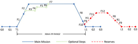
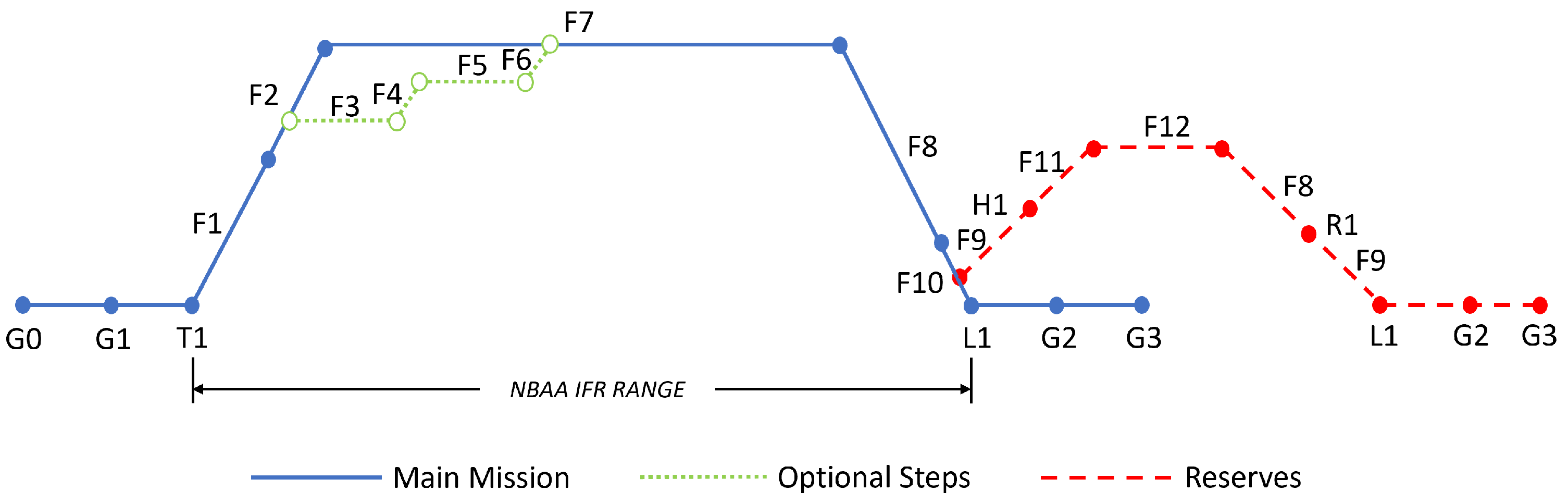
The typical flight profile for a very light jet is presented in Figure 1, and is based on the NBAA IFR Range and Aviation Week’s Business & Commercial Aircraft (BCA) profiles [12]. Descriptions of the individual stages of the profile are provided in Table 2. The rules allow for up to two optional 2000 ft increments to reduce fuel burn. The stepped climb is utilized to allow the aircraft to reduce weight through fuel burn before climbing to the optimum cruise altitude. It must be noted that this is a standard ideal range methodology, and actual flight profiles are dependent on a number of factors, including airspace, ATC, and weather.
Figure 1.
Typical NBAA cruise mission profile for a very light business jet. Descriptions of the phases are provided below in Table 2.
Table 2.
Descriptions for a typical NBAA IFR range profile.
For the above flight profile, the majority of VLJs have maximum cruise speeds between Mach 0.60 and Mach 0.70. Maximum range with four passengers for current very light jets averages 2037 km (1100 nmi). Table 3 presents a comparison of current and recent VLJs.
Table 3.
Comparison of range and maximum cruise performance for common VLJs. MTOW is also provided as reference [12,13,14].
The significant VLJ shipments and continued growth of this segment of business aviation make research into the feasibility of hybridization imperative. The constraints imposed by the small size and comparatively low weight of VLJs necessitate a dedicated examination, separate from other business jet classes. This paper aims to provide the first published research to determine the following:
- 1.
- The corresponding range is achievable for a VLJ from a given degree of energy hybridization for series and parallel hybrid-electric architectures under fixed Maximum Takeoff Weight (MTOW) assumptions.
- 2.
- Estimated fuel and emission reduction for a typical mission.
- 3.
- An optimal architecture for a potential first-generation hybrid-electric VLJ.
2. Background
In general terms, electrified aircraft propulsion (EAP) can be categorized into three distinct branches based on energy source and powertrain architecture: turboelectric, hybrid-electric, and fully electric. For turboelectric systems, all the energy is derived from a fuel source such as 100LL AvGas or Jet-A. Fully electric systems are powered by energy stored in batteries, or other electrical energy storage devices. Hybrid-electric systems are a combination of the turboelectric and full-electric schemes, in that they store and utilize energy from fuel and electrical energy sources, typically Jet A and batteries. On HEP systems, the energy may be used from storage sources individually, or simultaneously, depending on the power requirement for a given flight phase [5,15,16].
Within hybrid-electric propulsion systems, there are three primary architectural classifications: series, parallel, and series/parallel. Each of the configurations offers different advantages but also certain drawbacks. In this paper, the primary architectures of interest are the series and parallel schemes.
2.1. Series Architectures
The series HEP architecture is characterized by completely electric thrust generation. As is seen in Figure 2, the sequence of converting energy into thrust is sequential and linear. The process begins with fuel energy converted to electrical power via a turbogenerator, which is architecturally an electrical generator connected to a turboshaft via gearing. Electrical power from the generator is transformed by the power converter to an appropriate electrical current and voltage condition for the electric motor or to recharge the battery. The power converter also converts electrical power from the battery to the appropriate condition for the electric motor. The electrical motor then converts the electrical power into mechanical power to be used by the thrust-generating fan or propulsor [5,17]. The energy to thrust conversion on the series drivetrain can thus be divided into three distinct paths—fuel to shaft, battery to shaft, and shaft to thrust [18]. Table 4 provides the efficiency factors for each path.
Figure 2.
Simplified diagram of a series architecture. Black arrows represent fuel paths, blue arrows electric paths, and green arrows mechanical paths [11].
Table 4.
Drivetrain efficiency paths for a series architecture [11,18]. Subscripts are as follows: tg—turbogenerator, pc—power converter, em—electric motor, gb—gearbox, and p—propulsor fan/propeller.
The advantage of transmitting power electrically, as in a series system, is that it allows for decoupling of the turbogenerator and propulsor. The decoupling enables a distributed architecture to be used. However, the conversion of mechanical energy to electrical, and back to mechanical also introduces certain inefficiency, as seen in Table 4. The additional steps and components also add to the overall weight of the system [5,16], as demonstrated subsequently.
2.2. Parallel Architectures
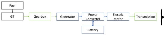
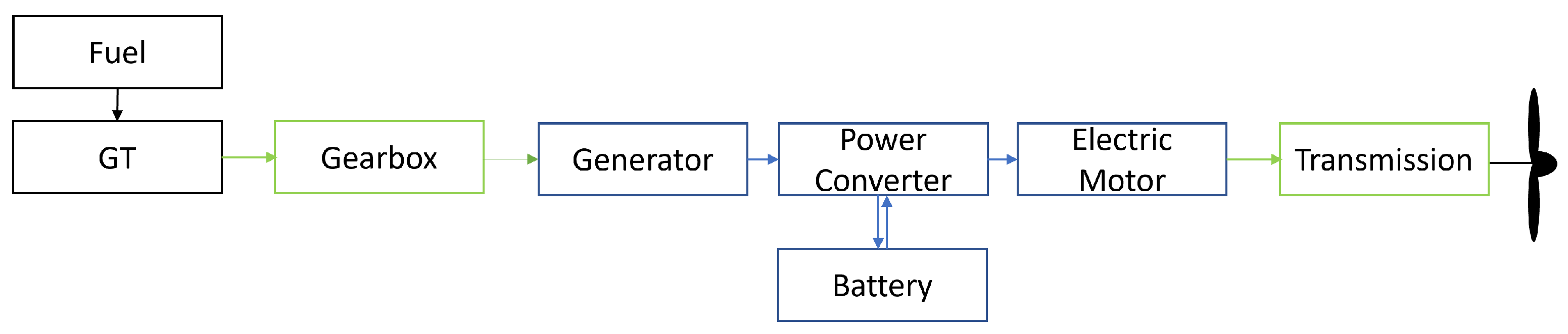
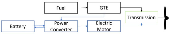
In a parallel architecture, thrust is produced by the summation of mechanical power directly from the engine, as well as from the electrical motor. This is achieved by coupling the electric motor to the propulsor or low-spool shaft of the turbofan engine with a transmission gearbox. An accessory generator on the turbofan engine provides electricity to power the electric motor, or to recharge the batteries. The electricity produced by the accessory generator is appropriately conditioned by the power converter. Figure 3 illustrates the parallel HEP system. Similar to the series system, the energy to thrust path for a parallel system can also be split into three distinct elements. The paths and corresponding efficiency factors are presented in Table 5.
Figure 3.
Simplified diagram of a parallel architecture. Black arrows represent fuel paths, blue arrows electric paths, and green arrows mechanical paths [11].
Table 5.
Drivetrain efficiency paths for a series architecture [11,18]. Subscripts are as follows: tf—turbofan, pc—power converter, em—electric motor, gb—gearbox, and p—propulsor fan/propeller.
Due to the ability to generate thrust from the turbofan and electric motor in conjunction or independently, the parallel system offers operational flexibility [15,16,17,18]. Nonetheless, the gearbox coupling adds complexity to the system [4]. Additionally, while lighter than series schemes, parallel architectures are still relatively heavier than conventional turbofans [5].
2.3. Electrical Components
Based on the schematic diagrams for the series and parallel architectures, it becomes evident that the efficiency and weight of the electrical components play a significant role in the feasibility of applying hybrid-electric propulsion to very light jets. In practical application, electrical systems of 1 to 3 kV class are required [5]. Table 6 presents the predicted efficiency and specific power for electrical components in the 15-year timeframe.
Table 6.
Drivetrain efficiencies and specific power for electrical components of a HEP architecture.
2.4. Battery Technology
While batteries have specific energy densities an order of magnitude lower than Jet A fuel, they represent the most promising near-term technological solution for electrical energy storage on a future HEP VLJ aircraft. This is due to the high technological readiness and increasingly widespread adoption for short-range electric aircraft. Batteries also exhibit reasonable performance in terms of specific power, volumetric energy density and comparatively long cycle lives [31,32,33]. Table 7 presents the predicted cell-level performance within the next 15 years for some of the promising battery technologies.
Table 7.
Approximate predictions of best performance for battery cells in the next 15 years.
From Table 7, it becomes evident that there is a wide range of predictions for battery-specific energy density over the next 15 years. While Li-air and Li-S offer the potential for significantly superior energy performance compared to Li-ion batteries, factors including future cycle life and production readiness are to be determined. Consequently, it is imperative to investigate the range of specific energy densities from 400 Wh/kg to 1250 Wh/kg.
3. Methodology
3.1. Baseline Aerodynamic Model
The methodology of this paper is based on that presented in [11] with the appropriate modifications for a VLJ aircraft. The first step in the process is to define the performance of a conventional turbofan baseline aircraft model, to which the series and parallel HEP configurations may be compared. Using the twin-engine aircraft presented in Table 3, general weight information for the aircraft class was established as an approximate composite average of the larger VLJs provided in Table 3, namely the CE-525, HA-420, and EMB-500. The resulting weights are presented in Table 8. Additional specifications and parameters required for the simulation are presented in Table 9 using information from manufacturer specification data sheets and [12,41], averaged over combinations of the three representative aircraft. Powerplant values are based around a Williams FJ44-1, which is utilized on numerous VLJs and other light jets.
Table 8.
Weights for a generalized baseline very light jet class aircraft.
Table 9.
Other specifications for a baseline VLJ.
3.2. Turbofan Baseline Performance Simulation
The previously developed MATLAB 2018a performance simulation consists of multiple distinct segments that enable range and energy consumption to be determined. These phases comprise a takeoff over a 50 ft obstacle, a climb to a given cruise altitude at the maximum rate of climb, cruise at an assigned Mach number, and a steady descent at a rate to an altitude of 5000 ft. This main mission block is followed by a reserve block, which includes a missed approach and climb; cruise of 185 km (100 nmi) at best economy cruise at an altitude of 10,000 ft; and, finally, steady descent to landing. The reserve mission also retains energy for the required 30 min of holding time.
The simulation is based on quasi-steady-state assumptions to determine the aircraft weight using a forward Euler time-stepping computational method. For every sequential one-second increment of time, the simulation recalculates aircraft lift, drag, velocity and weight based upon a starting weight. From these calculated parameters and the governing equations of motion, horizontal position and altitude are determined for every point in time. The equations are substantially derived from McCormick’s Aerodynamics, Aeronautics and Flight Mechanics [42]. Fuel and energy consumption, and consequently weight, are determined using the thrust production at a given time point.
For the takeoff and climb phase, the maximum rate of climb was determined across the range of flyable velocities from stall speed to . The stall speed was determined based on assumed maximum coefficient of lift . was assumed to be the true airspeed equivalent of Mach 0.73, based on the sample aircraft. For each velocity, was computed based on instantaneous aircraft weight. Thrust was held at a constant 90% of maximum available at any given altitude for the climb phase. Upon reaching the predetermined cruising altitude of 37,000 ft, thrust was set to equal the drag produced at a velocity of Mach 0.65. During descent, the simulation modulated thrust to maintain a constant rate of descent of 3000 ft per minute to 5000 ft.
3.3. Drag Buildup
Aerodynamic drag for the baseline aircraft model simulation comprises contributions from induced, profile and wave drag. Induced drag was calculated at each instant based on aircraft weight and velocity with an assumed Oswald’s span efficiency factor of . Zero-lift drag was calculated using the geometry-based semi-turbulent empirical estimations developed by [43]. Table 10 presents the geometric parameters used in the zero-lift drag calculations. Drag effects from leakage and protuberance were assumed to be an additional 5% to the zero-lift drag. Wave drag was determined based on a Mach drag-divergence of from the McDonnell method [43,44,45]. An additional 0.0003 counts of drag were added to the total drag account for trim effects [46].
Table 10.
Geometric values for a aerodynamic model used in the computation of induced and profile drag.
3.4. Power Required and Turbofan Power Available
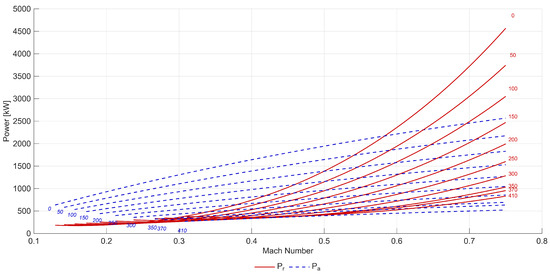
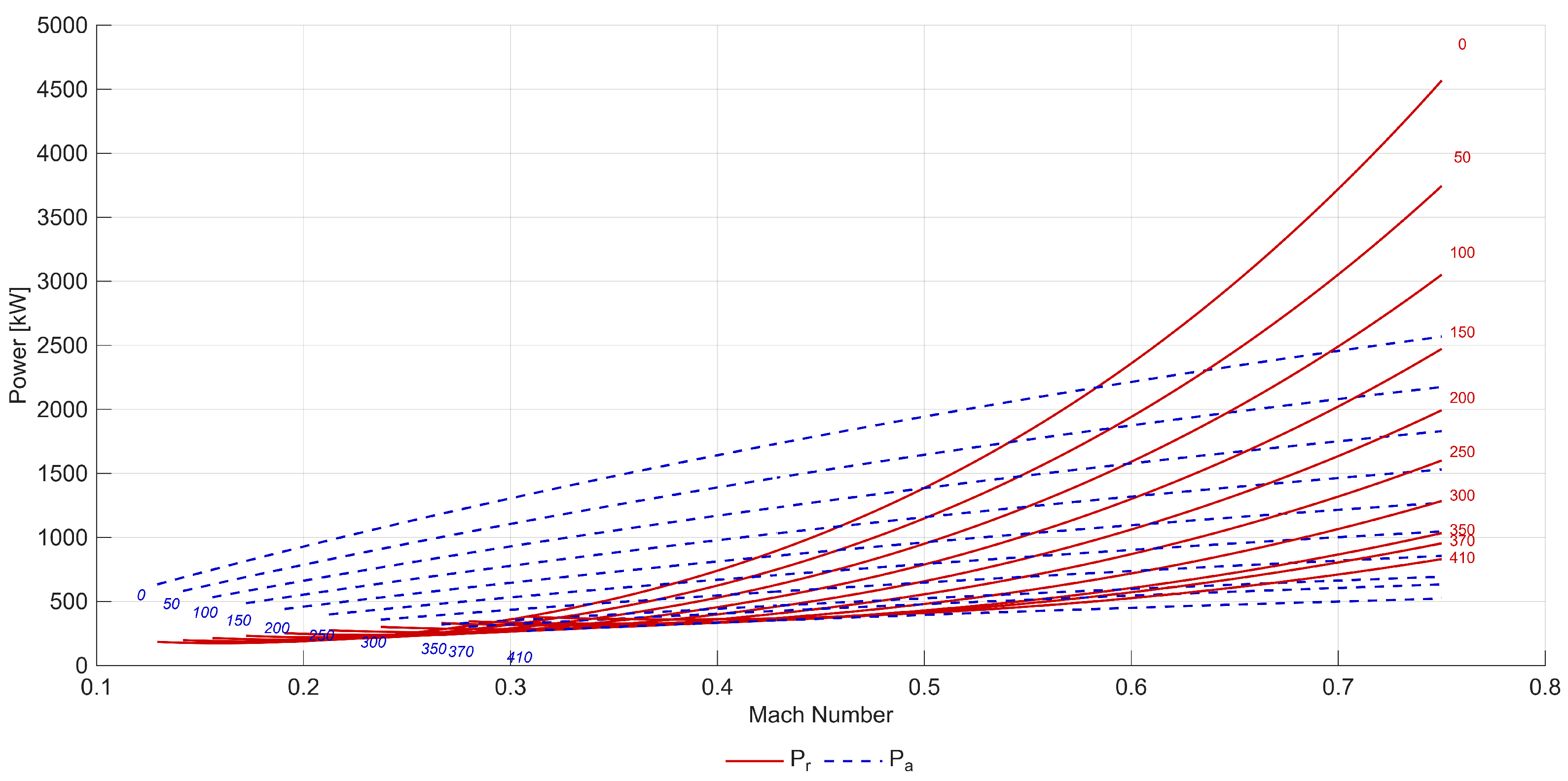
With the determination of drag for a given weight, velocity and altitude, the power required curves for the aerodynamic model are established. The power required curves are presented in Figure 4. Thrust available for the engine was determined using the equation presented in Equation (1), which corrects for altitude and Mach effects. A moderate throttle ratio (TR) common for smaller high bypass ratio engines, was used, such that . The throttle ratio describes the maximum turbine inlet temperature (TIT) at the operating altitude condition compared to the maximum TIT at sea level. For business jets, engines are typically optimized for maximizing efficiency at cruise-level conditions. The calculated available power has been overlaid onto the required power curves in Figure 4. The difference between the required and available power dictates the rate of climb, and the performance ceilings.
Figure 4.
Power required and power available for the VLJ model. Altitudes are provided in × 100 ft levels.
The determination of available propulsive power for the turbofan enables sizing of equivalent hybrid-electric architectures. Three points in the turbofan power available envelope are of importance— and at sea level, and at the ceiling. represents the stall speed of the aircraft, while represents the maximum speed at maximum continuous power. The sizing values of the delivered propulsive power are presented in Table 11. From the table, and Figure 4, the difference between the available power and required power also demonstrates the ability for One Engine Inoperative capabilities.
Table 11.
Critical single-engine propulsive power available conditions.
3.5. Turbofan Weight
In order to ascertain the additional weight imposed by the series and parallel architectures, the baseline turbofan weight must be established. This was determined from the average thrust-to-weight ratio for engines utilized on this class of aircraft, including the Pratt & Whitney Canada PW617, GE Honda HF 120, and Williams FJ33 and FJ44 engines, which average 0.0493 kN/kg (5.03 lbf/lb). Based on this average, an 8.90 kN (2000 lbf) engine can be expected to weigh approximately 180.44 kg (397.87 lbs) dry. In order to estimate the wet engine weight, an additional 5% was added to the dry weight. Consequently, total wet engine weight was found to be 189.46 kg (417.76 lbs).
3.6. Hybrid-Electric Drivetrain Sizing
Utilizing the calculated single-engine propulsive power of 2219 kW, the series and parallel architectures can be sized. Since the propulsive power was determined based on delivered thrust, the preceding components on the drivetrain must be enlarged to account for losses in the energy path. The efficiency losses for the series architecture are provided by Table 4. Table 5 provides the efficiency for the parallel drivetrain. Once the power ratings for the individual components are determined, weights are obtained by dividing by the specific power. The predicted efficiencies and specific powers of the electrical components are available in Table 6. Additionally, the propeller gearbox was assumed to have an efficiency of 0.99 and specific power of 100.0 kW/kg, and the combining transmission gearbox an efficiency of 0.99 and specific power of 50.0 kW/kg [47,48]. Propulsor efficiency was taken to have an efficiency of 0.85 and specific power of 13.0 kW/kg [5,20,49]. To account for wet weight, turbomachinery weight was multiplied by 1.05 on account of lubricants and accessory pads. The electric motor weight was increased by 3% as they require lubricants as well.
The total weight for the series architecture was found to be 384 kg (846 lbs). The power and weights for individual components of the series drivetrain are presented in Table 12. Given the multitude of components in a series system, the individual weights are based on optimistic trends for the predicted specific power spectrum.
Table 12.
Weight estimate of a serial architecture hybrid-electric propulsion system.
Similarly for the parallel architecture, Table 13 presents the power and weight at the drivetrain component level, for a total weight of 214 kg (473 lbs). The parallel sizing was predicated upon a power hybridization (motor power ratio) of 25%, where the motor provides 25% of total installed power capability. This power ratio was found to provide reasonable fuel savings in other studies [20,50,51,52,53,54]. Since electric motors have lower specific powers than turbofan engines, capping the motor at 25% enables hybridization without adding excessive weight to the power plant installation. While increasing power hybridization results in superior overall powertrain propulsive efficiency, it also comes at the cost of added system weight. The turbofan was proportionally scaled to deliver the remaining 75% of propulsive power at sea level , rather than using the less conservative method by [43].
Table 13.
Weight estimate of a parallel architecture hybrid-electric propulsion system.
3.7. Hybrid-Electric Simulation
Having determined the weights of the series and parallel HEP systems, it becomes possible to determine the new 4-passenger fuel weight for the very light jet model such that the aircraft retains an MTOW of 4852 kg (10,700 lbs). The weight deltas between the turbofan configuration and the HEP architectures are presented in Table 14.
Table 14.
Weight modifications to the available energy weight for two power plants.
The developed simulation was then modified to utilize the new energy weights for the series and parallel hybrid-electric propulsion systems. For both HEP architectures, energy consumption was configured to prioritize depletion of fuel over batteries. This enables a greater reduction in aircraft weight earlier in flight, improving overall range. Consequently, for the series architecture, the climb and cruise phases were biased towards energy draw from the turbogenerator before battery energy. For the parallel scheme, thrust was developed through the simultaneous use of the turbofan and electric motor, as the electric motor is not sufficiently powerful for individual operation. The HEP reserve mission fuel allocation of approximately 272 kg (600 lbs) was also modified to include a proportion of battery equivalent no greater than the 4-passenger energy weight hybridization ratio.
To account for the broad range of predicted battery-specific energy densities, the simulation was swept across a range of Wh/kg. Energy hybridization ratios considered ranged from in increments of 0.01, where is the ratio of energy stored in batteries to the total stored energy such that . For each specific energy density combination, total energy weight was fixed to 911 kg (2008 lbs) for the series HEP and 1134 kg (2634 lbs) for the parallel configuration.
3.8. Validation of Simulation
Finally, in order to verify the applicability of the developed time-stepping point-mass simulation for a very light jet, the turbofan methodology was evaluated using known geometric and weight parameters for the Cessna CE-525 aircraft. The Cessna CE-525 has an MTOW of 4853 kg (10,700 lbs) and an Operating Empty Weight (OEW) of 3170 kg (6990 lbs), values relatively similar to the representative baseline. A comparison of the simulated results for the CE-525 is presented against a combination of brochure data from [13,55] and the AFM [56].
As is seen in Table 15, the simulation methodology provides performance values sufficiently close to published data for the CE-525. The accuracy is in the same order of magnitude as the validation provided in [11] for a large-cabin jet. Even though the developed methodology does not account for transitions between flight phases, such as between takeoff and climb, or climb to cruise, the transition periods are relatively short compared to the overall mission. As a result, the methodology is adequate to provide a first-order analysis of hybridized aircraft performance.
Table 15.
Validation of simulation methodology for energy consumption and range parameters.
4. Results and Discussion
4.1. Range
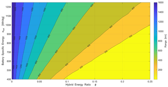
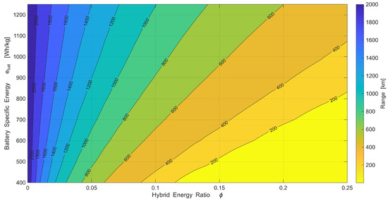
The results of the simulation parametric sweep over the array of battery-specific energy density and hybridization ratios for the series and parallel are presented as contour plots in Figure 5 for the series architecture and Figure 6 for a parallel scheme. As expected, increasing hybridization substantially reduces mission range. While increasing battery energy helps recover some of the lost range, the gradient of the contours demonstrates that range is overall more sensitive to the hybridization ratio. This is because hybridization displaces more fuel energy with battery energy than is gained by increasing specific energy density, which at 1250 Wh/kg is still about a tenth that of Jet A at 11,950 Wh/kg. Table 16 and Table 17 respectively provide the ranges for the series and parallel HEP architectures for a variety of hybridization and energy density ratios.
Figure 5.
Parametric contour plot for range against hybridization ratio and battery specific energy density for the series configuration.
Figure 6.
Parametric contour plot for range against hybridization ratio and battery specific energy density for the parallel configuration.
Table 16.
Range for combinations of hybridization ratio and specific energy density for a series HEP architecture.
Table 17.
Range for combinations of hybridization ratio and specific energy density for a parallel HEP architecture.
Based on the contour plots and tables, it becomes evident that battery-specific energy densities of less than 400 Wh/kg are insufficient for a hybridized VLJs with practical range. While 800 Wh/kg batteries are more promising, substantial range is only achievable with hybridization ratios of less than 5%, a value below which hybridization is very marginal even for a mild-hybrid concept. Batteries of between 1 kWh/kg and 1.25 kWh/kg demonstrate superior potential for feasible HEP very light business jets with meaningful degrees of hybridization.
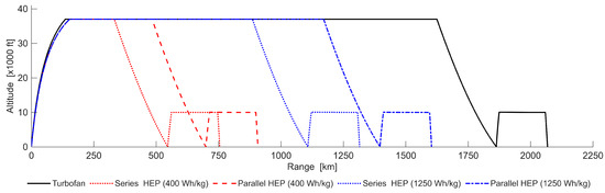
Figure 7 compares the ranges for the series and parallel architectures at a 5% hybridization against the turbofan baseline for the most conservative Wh/kg and most optimistic Wh/kg predictions for battery specific energy. As is seen in the figure, the turbofan aerodynamic model has a 4-passenger range of 1863 km (1006 nmi), which is within the typical flight range of twin-engine very light jet aircraft such as those listed in Table 3. With 1250 Wh/kg batteries, the series architecture has a range of 1116 km (603 nmi) and the parallel scheme a range of (1397) 754 nmi. While neither hybrid architecture reaches the typical maximum range of twin-engine VLJs with four passengers, the parallel scheme’s range is superior to single-engine VLJs like the Cirrus SF50’s. The 754 nmi range of the parallel system is also 94% the range of the Eclipse EA-500 series, the shortest-range twin-engine VLJ.
Figure 7.
Series and parallel HEP architectures at compared with turbofan mission profile.
4.2. Fuel and Battery Consumption
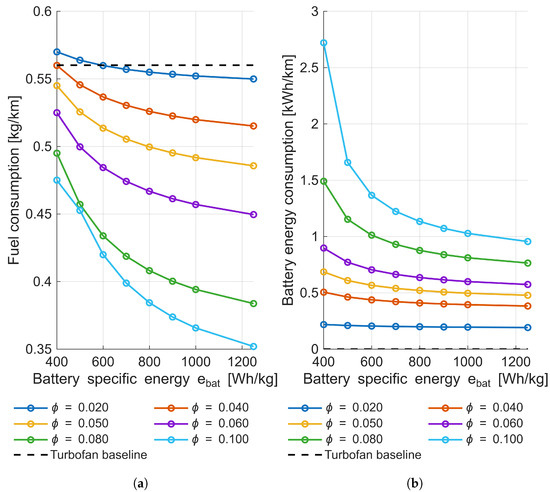
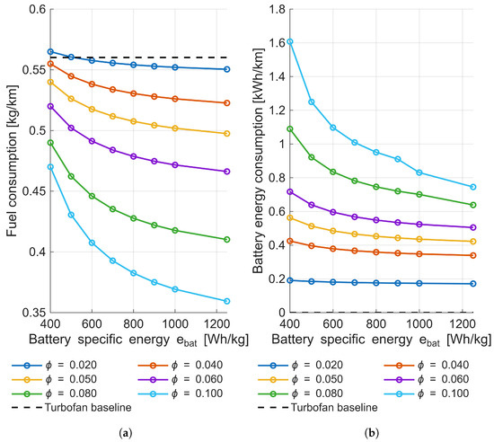
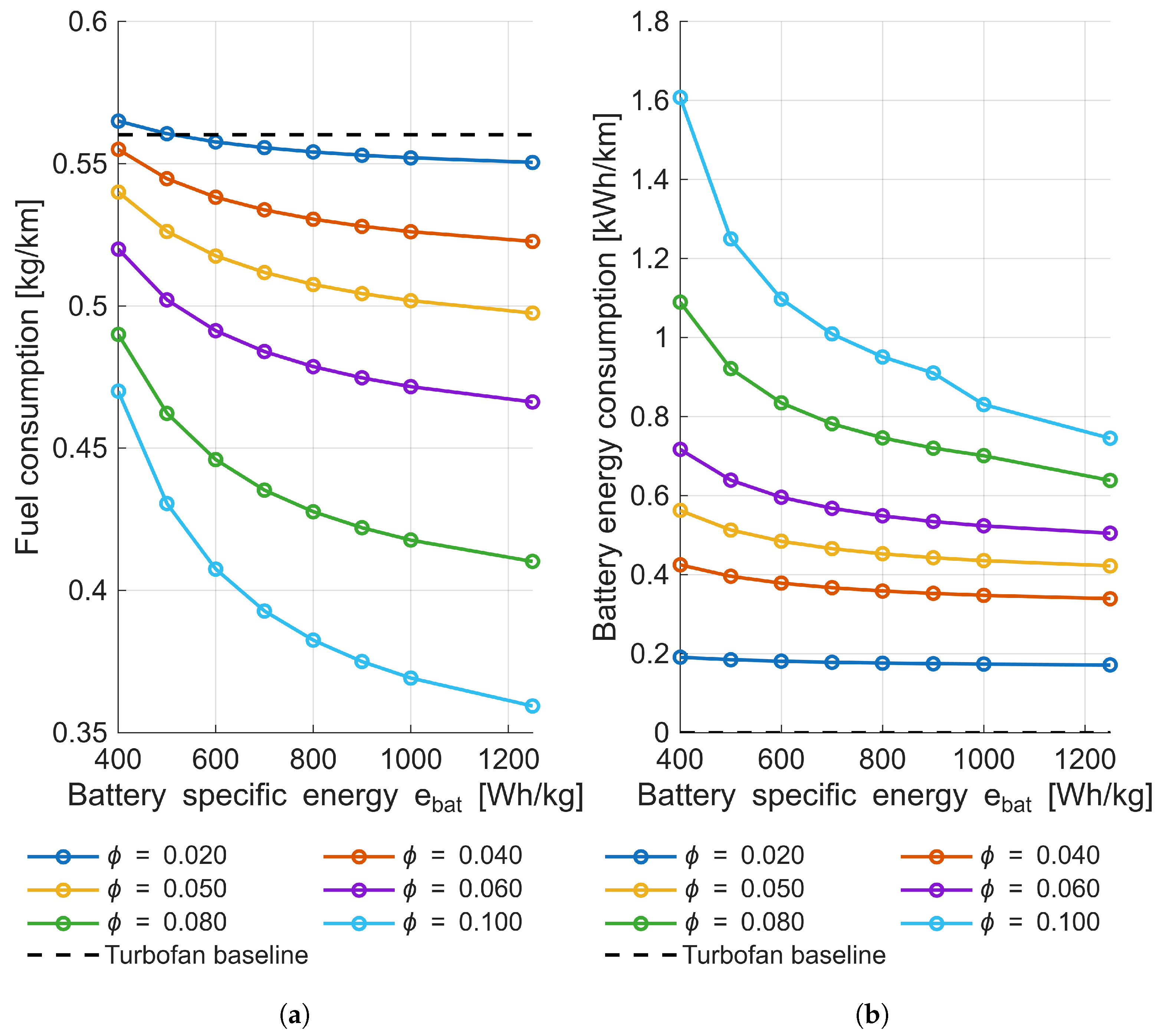
In order to determine whether the fuel-saving purpose of hybridization is accomplished, the fuel consumption of the series and hybrid configurations must also be examined. Figure 8 and Figure 9 present the mission-average fuel burn and battery consumption per distance of range.
Figure 8.
Series architecture fuel and battery energy consumption per km of range against specific energy density. (a) Fuel consumption for various hybridization ratios; the dashed black line is the baseline turbofan model. (b) Battery consumption for various hybridization ratios.
Figure 9.
Parallel architecture fuel and battery energy consumption per km of range against specific energy density. (a) Fuel consumption for various hybridization ratios; the dashed black line is the baseline turbofan model. (b) Battery consumption for various hybridization ratios.
As seen in the figures, increasing the hybridization ratio enables a significant reduction in fuel burn and a commensurate increase in battery energy consumption. This occurs due to the increasing replacement of fuel energy with battery energy. Fuel consumption similarly decreases with increasing battery specific energy, as more battery energy is carried for a given energy weight. However, the fuel burn improvement per unit range is substantially less drastic than for hybridization ratio variation. Consequently, HEP architectures with low specific energies of up to 400 Wh/kg and low hybridization of less than 5% burn more fuel for a fixed distance than the turbofan configuration because of the increased aircraft empty weight. However, mild hybridization ratios of 5% to 10% combined with high specific energy density of 1000 Wh/kg to 1250 Wh/kg can reduce fuel burn substantially for fixed distances within the range capabilities of the particular hybridization and specific energy density combination.
4.3. Battery Weight and Volume Distribution
Among the primary challenges of hybridization of a very light business jet aircraft are accommodation for batteries in terms of weight and volume. VLJs have small relatively small, weight and balance margins to remain within stability limits. Table 18 and Table 19, respectively, provide the weights and volumes for series and parallel architectures with varying levels of hybridization with 1250 Wh/kg batteries. The batteries were assumed to have a volumetric energy density of 360 Wh/L.
Table 18.
Weights and volumes for 1250 Wh/kg batteries on the series architecture VLJ model.
Table 19.
Weights and volumes for 1250 Wh/kg batteries on the parallel architecture VLJ model.
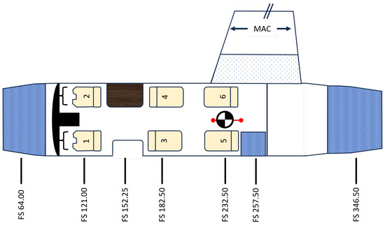
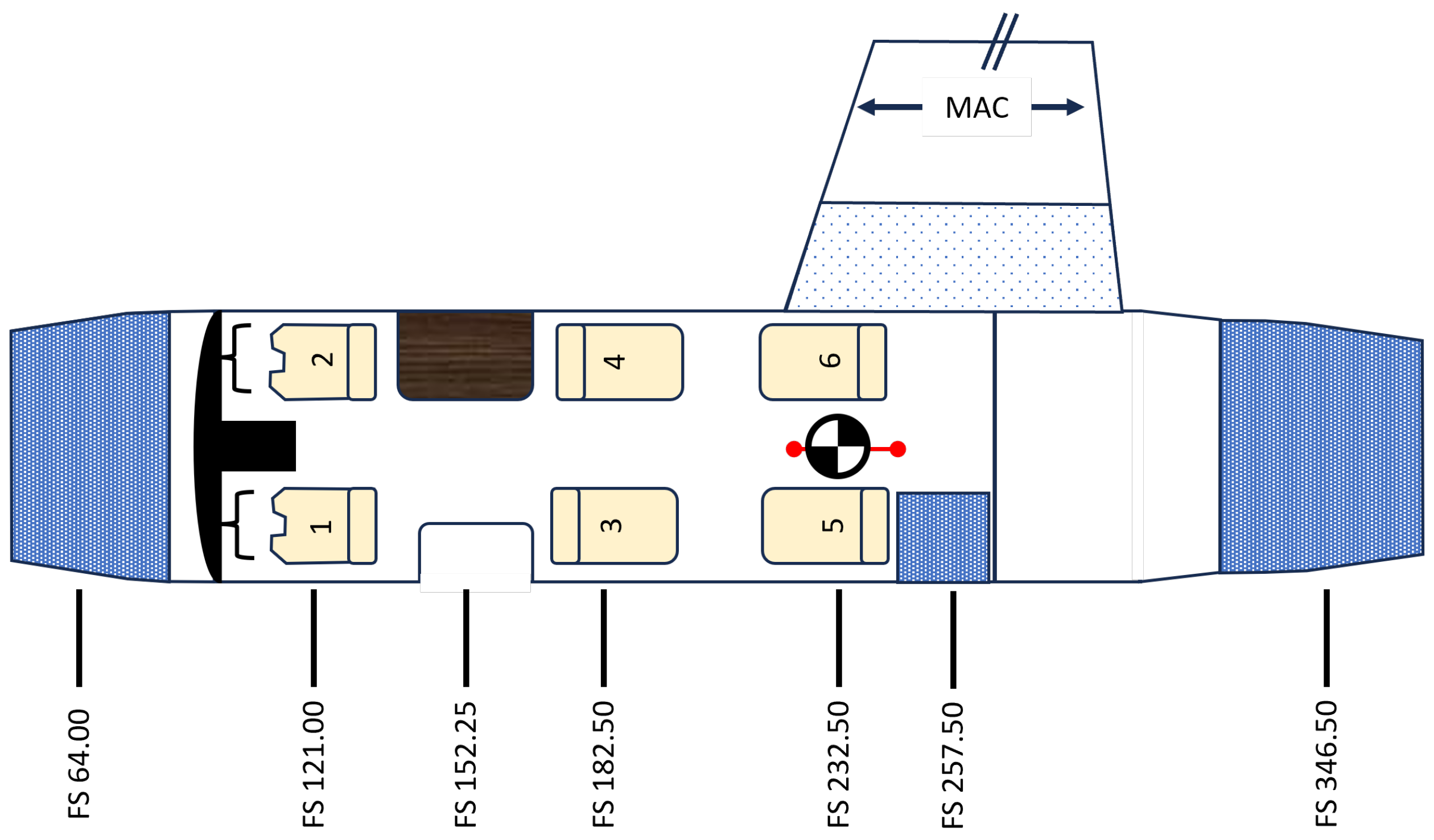
As is seen from the tables, batteries comprise a substantial weight and volume, even at mild hybridization ratios of around 5%. Figure 10 illustrates a representative VLJ aircraft with three baggage storage areas—forward, cabin, and aft. Space available is on the order of 850 L (30 ft3), 283 L (10 ft3) and 1133 L (40 ft3), respectively, for the baggage compartments, in addition to space made available in the wings by replaced fuel storage volumes. Aircraft CG limits are +31.8 mm (+1.5”) forward and +152.4 mm (+6") aft of empty CG. In a series configuration, battery weight must be distributed further forward than in a parallel configuration on account of the heavier powertrain. While both series and parallel configurations can be volumetrically accommodated within the representative CG margins, the greater weight of the series power plant results in an aft-heavy aircraft, even with both crew seats occupied. The distribution of batteries around the aircraft would also necessitate appropriate structural modifications to support additional weight. The relatively constant weight and volume of batteries also reduces the ability to modulate aircraft trim through fuel consumption, potentially requiring greater use of control surfaces to maintain pitch attitude, increasing aerodynamic drag in the process. Despite the challenges, it is worth noting that the fixed mass of batteries also offers potential advantages in terms of reducing wing bending and thus wingbox structural weight when batteries are accommodated in the wings [57].
Figure 10.
Representative illustration of available space on a VLJ. Baggage compartments are crosshatched in blue. The dotted area in the wing depicts the space made available in the wing by the displacement of fuel.
4.4. Typical Mission
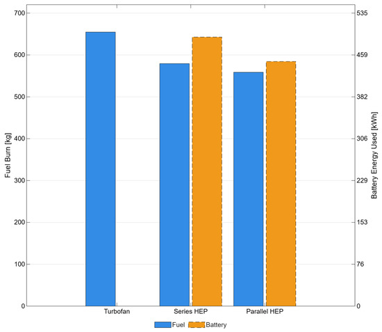
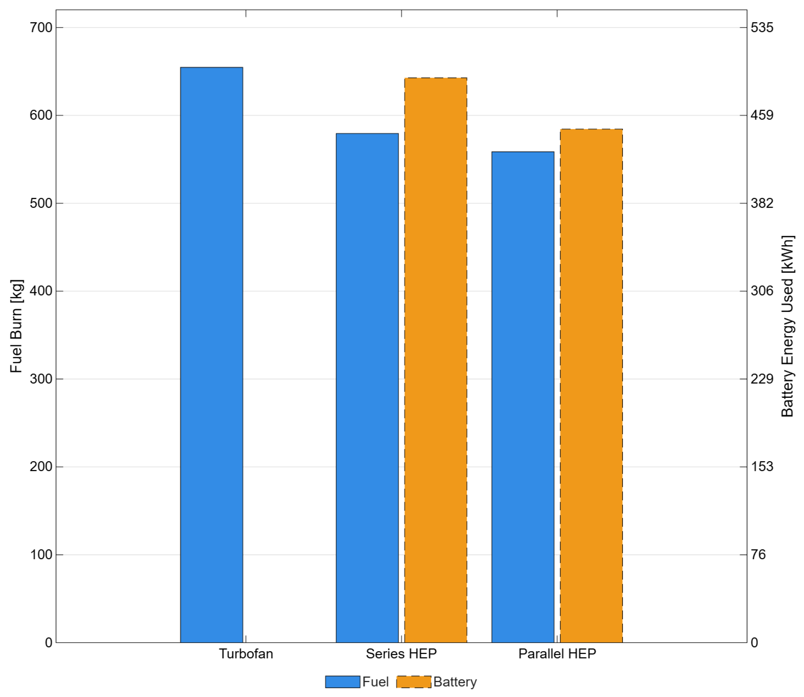
Based on a mild hybridization ratio of 5% and the best-case battery-specific energy of 1250 Wh/kg, an exemplary 1100 km (600 nmi) mission at MTOW can be examined. This range encompasses the great circle distances for routes such as New York City–Charlotte, NC; Miami, FL–Atlanta, GA; Seattle, WA–San Francisco, CA; or London–Berlin. Figure 11 and Table 20 present the fuel and battery energy consumption for the turbofan, serial and parallel configurations.
Figure 11.
Fuel and battery energy consumption over a 1100 km (600 nmi) mission at aircraft MTOW. The blue bars correspond to fuel consumption, whilst the orange bars with dashed outlines correspond to battery energy consumption.
Table 20.
Energy consumption for a 1100 km (600 nmi) Mission with and Wh/kg.
The turbofan model consumed approximately 655 kg (1444 lbs) over the mission, while the series and parallel architectures consumed 580 kg (1279 lbs) and 559 kg (1233 lbs), respectively. In addition to fuel consumption, the series scheme utilized 492 kWh of battery energy. In contrast, the parallel HEP configuration utilized 446 kWh of battery energy. Overall fuel savings for the mission are 75 kg (165 lbs) and 96 kg (212 lbs) for the respective series and parallel hybrid architectures. Despite the relatively small overall savings, these savings represent fuel burn reductions of 11.5% and 14.65% against the turbofan baseline.
The fuel savings equate to a reduction in typical mission emissions of approximately 101 kg (224 lbs) of CO2 for the series system and 197 kg (435 lbs) for the parallel system from fuel sources, based on an average 3.775 weight ratio of CO2 emissions per unit of Jet A, and a US average of 0.367 kg (0.81 lbs) of CO2 per kWh of electricity generation.
The typical mission analysis also confirms that a mild hybridization of around 5% is about the lowest ratio warranted on a VLJ. When used for propulsion purposes, lower energy hybridization ratios provide diminishing returns in terms of fuel burn reduction while incurring losses from added power plant weight and fixed battery weight.
5. Conclusions
The results and analysis of the simulation demonstrate and confirm the conceptual feasibility of hybrid-electric propulsion for very light jets, albeit with reduced ranges compared to typical aircraft of the class. While the representative aerodynamic model was able to achieve a four-passenger NBAA IFR range of 1863 km (1006 nmi), the series and parallel HEP architectures with a mild hybridization ratio of 5% were limited to 1116 km (603 nmi) and 1397 km (754 nmi), respectively, under the same conditions with the optimistic battery prediction of 1250 Wh/kg by 2040. While sub-one-thousand nautical mile ranges are shorter than twin-engined aircraft of the VLJ class, the series range is comparable to the 622 nmi range of the single-engine Cirrus SF50. The parallel architecture enables superior range over the SF50. This demonstrates that a hybridized twin-engine VLJ still retains adequate performance within the current aircraft class bounds.
The better overall range of the parallel hybrid-electric architecture is a result of incurring a smaller weight penalty than for the series, thereby leaving more weight available for energy storage for a similar maximum takeoff weight. The lower empty aircraft weight for the parallel configuration also enables superior fuel savings. For a 1100 km (600 nmi) mission at and Wh/kg, the parallel system reduces fuel consumption by approximately 14.7% relative to the turbofan baseline, while the series configuration yields a reduction of about 11.5%. These gains in fuel efficiency are accompanied by slight reductions in total mission energy on account of the superior overall efficiency of hybrid-electric powerplants. As a result, VLJs utilizing mildly hybridized parallel architectures in conjunction with Sustainable Aviation Fuels (SAFs) would enable significant reductions in emissions.
The parallel configuration also has advantages over the series architecture in terms of technological readiness and implementation. Since parallel systems retain sizable turbofans, smaller and less powerful electrical components are required, lending to easier integration within the pylon-nacelle structure. Less powerful motors and power electronics are likely to be technologically ready for use sooner than more powerful systems with higher specific powers.
Apart from providing the requisite performance to fulfill ConOps in terms of performance, a mild hybridization ratio also enables the hybrid aircraft to operate in areas with limited charging infrastructure. VLJs frequently operate routes between airport pairs with limited flight services, which may or may not have on-ground charging infrastructure.
Based on these findings, it is recommended that the development of a future hybrid-electric VLJ utilize a parallel architecture with mild hybridization of around 5%. Additionally, it is recommended that the minimum battery-specific energy required for a feasible HEP very light jet business aircraft be at least 1250 Wh/kg.
Nonetheless, it should also be emphasized that this is a top-level study of the feasibility of hybrid-electric very light jet business aircraft in terms of performance based on optimistic battery predictions. Nominal predictions based on historical trends indicate substantially lower battery-specific energy densities at below 1000 Wh/kg. Recurrent maintenance costs and aircraft availability are also concerns for hybrid-electric aircraft, as battery packs would need replacement after reaching a certain minimum performance. As a result, while hybrid-electric VLJs may be feasible from a ConOps standpoint, they may not be economically viable. Finally, certification pathways and industry standards still need to be defined prior to or during the development of any potential hybrid-electric VLJ aircraft.
6. Future Research, Work and Opportunities
Numerous other considerations must also be examined in detail before a manufacturer could consider an engineering program. While this paper utilizes the best available predictions for power plant weight and component efficiency, future performance of constituent hybrid-electric components may not reach predicted levels. As a result, it would certainly be worthwhile to perform sensitivity studies for the less-developed and heavier components. Other factors such as structural integration, and battery and power plant thermal requirements are also critical for determining the potential for undertaking a hybrid-electric VLJ project. Market studies and the consultation of VLJ owners and operators would also be necessary to determine the demand for a hybridized VLJ and the impact on operational impacts due to reduced aircraft availability when charging batteries on the ground.
Funding
This research received no external funding.
Data Availability Statement
All relevant data are included as figures or tables in the main article. Further inquiries can be directed to the corresponding author.
Acknowledgments
The author would like to thank Jason Merret, Phil Ansell and Leon Liebenberg of the University of Illinois Urbana-Champaign and Hao Huang of the University of Houston for their advice, suggestions and feedback. The author would also like to acknowledge the support of Shyam Fulena and Jagadish Soobarah.
Conflicts of Interest
The author declares no conflicts of interest.
Abbreviations
The following abbreviations are used in this manuscript:
| AC | Alternating Current |
| AFM | Airplane Flight Manual |
| ALT | Altitude |
| APCH | Approach |
| ATC | Air Traffic Control |
| BPR | Bypass Ratio |
| DC | Direct Current |
| ESAR | Energy Specific Air Range |
| FADEC | Full Authority Digital Engine Controller |
| GAMA | General Aviation Manufacturers Association |
| HEP | Hybrid-Electric Propulsion |
| IBAC | International Business Aviation Council |
| ICAO | International Civil Aviation Organization |
| IFR | Instrument Flight Rules |
| LVL | Level |
| MTOW | Maximum Takeoff Weight |
| NBAA | National Business Aviation Association |
| PAX | Passenger |
| RWY | Runway |
| SP | Specific Power |
| TSFC | Thrust-Specific Fuel Consumption |
| TR | Throttle Ratio |
| VLJ | Very Light Jet |
References
- Business Aviation Commitment on Climate Change Update 2022. 2022. Available online: https://www.ebaa.org/app/uploads/2024/02/BACCC_update_0523_A4.pdf (accessed on 1 October 2025).
- Business Aviation Commitment on Climate Change, General Aviation Manufacturers Assosciation. 2020. Available online: https://gama.aero/wp-content/uploads/GAMA-IBAC-Joint-Position-on-Business-Aviation-Tackling-Climate-Change-1.pdf (accessed on 11 November 2025).
- Hubbard, D. Business Aviation Pledges Net-Zero Carbon By 2050 and Increasing Fuel Efficiency as Part of Renewed Climate Commitments; NBAA-National Business Aviation Association: Washington, DC, USA, 2021. [Google Scholar]
- Rendón, M.A.; Sánchez, R.C.D.; Gallo, M.J.; Anzai, A.H. Aircraft Hybrid-Electric Propulsion: Development trends, challenges and opportunities. J. Control Autom. Electr. Syst. 2021, 32, 1244–1268. [Google Scholar] [CrossRef] [Scilit]
- National Academies of Sciences. Medicine. In Commercial Aircraft Propulsion and Energy Systems Research: Reducing Global Carbon Emissions; The National Academies Press: Washington, DC, USA, 2016. [Google Scholar] [CrossRef] [Scilit]
- Ianotta, B. Aerospace America: 2024 Year-in-Review; American Institute of Aeronautics and Astronautics: Reston, VA, USA, 2010; Volume 62, No. 11. [Google Scholar]
- Yeung, T.H. Optimal Battery Weight Fraction for Serial Hybrid Propulsion System in Aircraft Design. Master’s Thesis, Embry-Riddle Aeronautical University, Daytona Beach, FL, USA, 2019. [Google Scholar]
- Vincent, R. JETNET IQ Pulse Issue # 41. 2022. Available online: https://www.jetnet.com/hubfs/Jetnet_August2025/pdfs/documents_iq-pulse_JETNET%20iQ%20Pulse%20-%20May%2012%202022.pdf (accessed on 12 December 2025).
- Business Aviation Fact Book 2018; National Business Aircraft Assosciation. 2018. Available online: https://nbaa.org/wp-content/uploads/2018/01/business-aviation-fact-book.pdf (accessed on 5 December 2025).
- General Aviation Aircraft Shipments and Billings—Business Jets 1996–2024. 2025. Available online: https://gama.aero/wp-content/uploads/1.03-a-General-Aviation-Aircraft-Shipments-and-Billings-BusinessJets-1996-2024-2025-11-03.xlsx (accessed on 11 November 2025).
- Sarup, A. Application of Hybrid-Electric Propulsion to ‘Large-Cabin’ Business Aircraft. World Electr. Veh. J. 2025, 16, 530. [Google Scholar] [CrossRef] [Scilit]
- Shay, L.A.; McMillin, M.; Carey, B. BCA: Business & Commercial Aviation, May 2023 ed.; Aviation Week: New York, NY, USA, 2023.
- Garvey, W.; Salerno, J.A.; George, F.; Aarons, R.N. BCA: Business & Commercial Aviation, May 2018 ed.; Aviation Week: New York, NY, USA, 2018.
- Garvey, W.; Salerno, J.A.; George, F.; Aarons, R.N. BCA: Business & Commercial Aviation, May 2016 ed.; Aviation Week: New York, NY, USA, 2016.
- Bowman, C. Establishing Electrified Aircraft Propulsion Concepts: How AATT identified viable propulsion concepts and established foundational technologies. In Proceedings of the ARMD Technical Seminar 2018, Washington, DC, USA, 21–23 August 2018. [Google Scholar]
- Sahoo, S.; Zhao, X.; Kyprianidis, K. A Review of Concepts, Benefits, and Challenges for Future Electrical Propulsion-Based Aircraft. Aerospace 2020, 7, 44. [Google Scholar] [CrossRef] [Scilit]
- Xie, Y.; Savvarisal, A.; Tsourdos, A.; Zhang, D.; Gu, J. Review of Hybrid Electric Powered Aircraft, its Conceptual Design and Energy Management Methodologies. Chin. J. Aeronaut. 2021, 34, 432–450. [Google Scholar] [CrossRef] [Scilit]
- de Vries, R.; Hoogreef, M.F.; Vos, R. Range Equation for Hybrid-Electric Aircraft with Constant Power Split. J. Aircr. 2020, 57, 552–557. [Google Scholar] [CrossRef] [Scilit]
- Al Khoury, J.; Bou Nader, W. Design and simulation of turbogenerators for series hybrid electric vehicles. Energy Convers. Manag. 2021, 236, 114078. [Google Scholar] [CrossRef] [Scilit]
- Duffy, K.P.; Jansen, R.H. Turboelectric and Hybrid Electric Aircraft Drive Key Performance Parameters. In Proceedings of the 2018 AIAA/IEEE Electric Aircraft Technologies Symposium (EATS), Cincinnati, OH, USA, 9–11 July 2018; pp. 1–19. [Google Scholar]
- Spakovszky, Z.S.; Chen, Y.; Greitzer, E.M.; Cordero, Z.C.; Lang, J.H.; Kirtley, J.L.; Perreault, D.J.; Andersen, H.N.; Qasim, M.M.; Cuadrado, D.G.; et al. Technology Demonstration of a Megawatt-Class Integrated Motor Drive for Aircraft Propulsion. In AIAA AVIATION 2023 Forum; American Institute of Aeronautics and Astronautics, Inc.: Reston, VA, USA, 2023. [Google Scholar] [CrossRef] [Scilit]
- Jansen, R.; Bowman, C.; Jankovsky, A.; Dyson, R.; Felder, J. Overview of NASA Electrified Aircraft Propulsion (EAP) Research for Large Subsonic Transports. In Proceedings of the 53rd AIAA/SAE/ASEE Joint Propulsion Conference, Atlanta, GA, USA, 10–12 July 2017; NASA Glenn Research Center: Cleveland, OH, USA. [Google Scholar] [CrossRef] [Scilit]
- Teichert, E.; Kazula, S. Overview and Evaluation of Electric Machines for Electric Regional Aircraft Propulsion Systems. In Proceedings of the Deutscher Luft-und Raumfahrtkongress (DLRK) 2024, Hamburg, Germany, 30 September–2 October 2024. [Google Scholar]
- Hall, C.; Pastra, C.L.; Burrell, A.; Gladin, J.; Mavris, D.N. Projecting Power Converter Specific Power Through 2050 for Aerospace Applications. In Proceedings of the 2022 IEEE Transportation Electrification Conference & Expo (ITEC), Anaheim, CA, USA, 15–17 June 2022; pp. 760–765. [Google Scholar] [CrossRef] [Scilit]
- Pastra, C.L.; Hall, C.; Cinar, G.; Gladin, J.; Mavris, D.N. Specific Power and Efficiency Projections of Electric Machines and Circuit Protection Exploration for Aircraft Applications. In Proceedings of the 2022 IEEE/AIAA Transportation Electrification Conference and Electric Aircraft Technologies Symposium (ITEC+EATS), Anaheim, CA, USA, 15–17 June 2022; pp. 766–771. [Google Scholar] [CrossRef] [Scilit]
- Zhang, X.; Bowman, C.L.; O’Connell, T.C.; Haran, K.S. Large electric machines for aircraft electric propulsion. IET Electr. Power Appl. 2018, 12, 767–779. [Google Scholar] [CrossRef] [Scilit]
- Granger, M.; Anderson, A.; Maroli, J.M.; Tallerico, T.; Scheidler, J.J. Combined Analysis of NASA’s High Efficiency Megawatt Motor and Its Converter. In Proceedings of the 2021 AIAA/IEEE Electric Aircraft Technologies Symposium (EATS), Denver, CO, USA, 11–13 August 2021; pp. 1–13. [Google Scholar] [CrossRef] [Scilit]
- Tallerico, T.; Scheidler, J.J.; Lee, D.; Haran, K.S. Electromagnetic Redesign of NASA’s High Efficiency Megawatt Motor. In AIAA Propulsion and Energy 2020 Forum; American Institute of Aeronautics and Astronautics, Inc.: Reston, VA, USA, 2020. [Google Scholar] [CrossRef] [Scilit]
- Hall, D.; Greitzer, E.; Dowdle, A.; Gonzalez, J.; Hoburg, W.; Lang, J.; Sabnis, J.; Spakovszky, Z.; Yutko, B.; Courtin, C.; et al. Feasibility of Electrified Propulsion for Ultra-Efficient Commercial Aircraft Final Report; Technical report; NASA: Washington, DC, USA, 2019. [Google Scholar]
- WM2500: The Wright Motor. 2025. Available online: https://www.weflywright.com/products/motor (accessed on 5 November 2025).
- Dever, T.; Duffy, K.P.; Provenza, A.; Loyselle, P.L.; Choi, B.B.; Morrison, C.R.; Lowe, A.M. Assessment of Technologies for Noncryogenic Hybrid Electric Propulsion; Glenn Research Center: Cleveland, OH, USA, 2015. [Google Scholar]
- Christen, T.; Carlen, M.W. Theory of Ragone plots. J. Power Sources 2000, 91, 210–216. [Google Scholar] [CrossRef] [Scilit]
- Stephan, A.; Hettesheimer, T.; Neef, C.; Schmaltz, T.; Link, S.; Stephan, M.; Heizmann, J.L.; Thielmann, A. Alternative Battery Technologies Roadmap 2030+; Fraunhofer ISI: Karlsruhe, Germany, 2023. [Google Scholar] [CrossRef]
- Rheaume, J.M.; Lents, C. Energy storage for commercial hybrid electric aircraft. In SAE Technical Paper Series; SAE International: Warrendale, PA, USA, 2016. [Google Scholar] [CrossRef] [Scilit]
- Hariprakash, B.; Shukla, A.; Venugoplan, S. SECONDARY BATTERIES–NICKEL SYSTEMS|Nickel–Metal Hydride: Overview. In Encyclopedia of Electrochemical Power Sources; Garche, J., Ed.; Elsevier: Amsterdam, The Netherlands, 2009; pp. 494–501. [Google Scholar] [CrossRef] [Scilit]
- Quintero Pulido, D.F.; Covrig, C.F.; Bruchhausen, M. On the Performance of Portable NiMH Batteries of General Use. Batteries 2025, 11, 30. [Google Scholar] [CrossRef] [Scilit]
- Hepperle, M. Electric Flight—Potential and Limitations. In Proceedings of the Energy Efficient Technologies and Concepts of Operation; NATO Science and Technology Organization: Brussels, Belgium, 2012. [Google Scholar]
- Misra, A. Summary of 2017 NASA Workshop on Assessment of Advanced Battery Technologies for Aerospace Applications. In Proceedings of the 2018 SciTech Forum, Kissimmee, FL, USA, 8–12 January 2018. [Google Scholar]
- Johnson, L. The Viability of High Specific Energy Lithium Air Batteries. In Proceedings of the Symposium on Research Opportunities in Electrochemical Energy Storage-Beyond Lithium Ion, Oak Ridge, TN, USA, 7 October 2010. [Google Scholar]
- Tiede, B.; O’Meara, C.; Jansen, R. Battery Key Performance Projections based on Historical Trends and Chemistries. In Proceedings of the 2022 IEEE/AIAA Transportation Electrification Conference and Electric Aircraft Technologies Symposium (ITEC+EATS), Anaheim, CA, USA, 15–17 June 2022; pp. 754–759. [Google Scholar] [CrossRef] [Scilit]
- Jackson, P.; Peacock, L.; Bushell, S.; Willis, D.; Winchester, J. Jane’s All the World’s Aircraft: Development and Production; 2018–2019; IHS Markit: London, UK, 2018. [Google Scholar]
- McCormick, B.W. Aerodynamics, Aeronautics, and Flight Mechanics, 2nd ed.; Wiley: Hoboken, NJ, USA, 1995. [Google Scholar]
- Raymer, D.P. Aircraft Design: A Conceptual Approach, 2nd ed.; The American Institute of Aeronautics and Astronautics, Inc.: Reston, VA, USA, 1992. [Google Scholar]
- Kapania, R.; Schetz, J.; Mallik, W.; Segee, M.; Gupta, R. Multidisciplinary Design Optimization and Cruise Mach Number Study of Truss-Braced Wing Aircraft; Langley Research Center: Hampton, VA, USA, 2018. [Google Scholar] [CrossRef]
- Mason, W.H. 3. Drag: An Introduction. In AOE 4124 Configuration Aerodynamics; Virginia Polytechnic Institute: Blacksburg, VA, USA, 2019; p. 45. Available online: https://archive.aoe.vt.edu/mason/Mason_f/ConfigAeroDrag.pdf (accessed on 1 November 2025).
- Roskam, J. Some Comments on Trim Drag. In Proceedings of the NASA, Industry, University, General Aviation Drag Reduction Workshop, Lawrence, KS, USA, 14–16 July 1975; pp. 295–305. [Google Scholar]
- Kratz, J.L. Exploration of the Versatile Electrically Augmented Turbine Engine Gearbox Concept. In AIAA Propulsion and Energy 2021 Forum; American Institute of Aeronautics and Astronautics, Inc.: Reston, VA, USA, 2021. [Google Scholar] [CrossRef] [Scilit]
- Anderson, N.; Cerdoz, R.W.; Salama, E.; Wagner, D.A. Advanced Gearbox Technology. In NASA Contractor Report CR-179625; NASA Lewis Research Center: Cleveland, OH, USA, 1987. [Google Scholar]
- Felder, J.; Kim, H.; Brown, G. Turboelectric Distributed Propulsion Engine Cycle Analysis for Hybrid-Wing-Body Aircraft. In 47th AIAA Aerospace Sciences Meeting Including The New Horizons Forum and Aerospace Exposition; American Institute of Aeronautics and Astronautics, Inc.: Reston, VA, USA, 2009. [Google Scholar] [CrossRef] [Scilit]
- Wroblewski, G.E.; Ansell, P.J. Mission Analysis and Emissions for Conventional and Hybrid-Electric Regional Jet Aircraft. In Proceedings of the 2018 AIAA/IEEE Electric Aircraft Technologies Symposium, Cincinnati, OH, USA, 12–14 July 2018; American Institute of Aeronautics and Astronautics, Inc.: Reston, VA, USA. [Google Scholar] [CrossRef] [Scilit]
- Majka, A.; Muszyńska-Pałys, J. Analysis of the Performance of an Aircraft Powered by Hybrid Propulsion. Combust. Engines 2023, 193, 45–51. [Google Scholar] [CrossRef] [Scilit]
- Antcliff, K.R.; Guynn, M.D.; Marien, T.; Wells, D.P.; Schneider, S.J.; Tong, M.J. Mission Analysis and Aircraft Sizing of a Hybrid-Electric Regional Aircraft. In Proceedings of the 54th AIAA Aerospace Sciences Meeting, San Diego, CA, USA, 4–8 January 2016; American Institute of Aeronautics and Astronautics: Reston, VA, USA, 2016. [Google Scholar]
- Marien, T.V.; Blaesser, N.J.; Frederick, Z.J.; Guynn, M.D.; Kirk, J.T.; Fisher, K.; Schneider, S.; Thacker, R.P.; Frederic, P. Results for an Electrified Aircraft Propulsion Design Exploration. In Proceedings of the 2021 AIAA/IEEE Electric Aircraft Technologies Symposium (EATS), Virtual, 11–13 August 2021; pp. 1–16. [Google Scholar] [CrossRef] [Scilit]
- Dehesa, D.A.; Menon, S.K. Modeling of Hybrid-Electric Powertrain for Unmanned Aerial Systems. In AIAA Propulsion and Energy 2019 Forum; American Institute of Aeronautics and Astronautics, Inc.: Reston, VA, USA, 2019. [Google Scholar] [CrossRef] [Scilit]
- Citation M2 Gen3: Your Vision Meets Power. 2024. Available online: https://cessna.txtav.com/-/media/cessna/files/product-cards/citation/citation_m2_gen3_product_card.pdf (accessed on 25 October 2025).
- Corneil, W.W. FAA Approved Airplane Flight Manual Citation CJ1 Serials 525-0360 thru-0599; Cessna Aircraft Company: Wichita, KS, USA, 2000. [Google Scholar]
- Reuel, F.; van Wensveen, J.; Lampl, D.E.; Weckenmann, T. Low-Fidelity Aerostructural Wing Sizing for Battery-in-Wing Electric Commuter Aircraft. In AIAA SCITECH 2026 Forum; American Institute of Aeronautics and Astronautics, Inc.: Reston, VA, USA, 2026. [Google Scholar] [CrossRef] [Scilit]

Disclaimer/Publisher’s Note: The statements, opinions and data contained in all publications are solely those of the individual author(s) and contributor(s) and not of MDPI and/or the editor(s). MDPI and/or the editor(s) disclaim responsibility for any injury to people or property resulting from any ideas, methods, instructions or products referred to in the content. |
© 2026 by the author. Published by MDPI on behalf of the World Electric Vehicle Association. Licensee MDPI, Basel, Switzerland. This article is an open access article distributed under the terms and conditions of the Creative Commons Attribution (CC BY) license.