


Abstract
Future IoT, smart-city, and 6G ecosystems will increasingly use UAVs as autonomous nodes, creating demand for rapid yet traceable mission-to-airframe design workflows. This study evaluates whether a large language model (LLM) with retrieval-augmented generation (RAG) can convert a cargo-UAV mission brief into source-grounded preliminary sweep-angle ranges and whether one instantiated geometry remains compatible with downstream physics-based checks. An LLM first proposed broad ranges; a RAG stage, over a curated aerospace corpus, narrowed the three sweep intervals from a combined width of 25° to 7° (72% aggregate reduction) before CAD instantiation. The resulting tailless blended-wing geometry was screened with a SolidWorks 2025 Flow Simulation database spanning speed, angle of attack, sideslip, and elevon deflections. In the neutral-elevon, near-zero-sideslip slice, lift crossed the CAD-derived weight between 4° and 8° at 100 m/s and between 0° and 4° at 200 m/s. A three-level mesh check preserved force and moment signs. A nominal 6-DoF mission at 120 m/s over approximately 32 km remained within the prescribed corridor, with late mean cross-track and altitude-path errors of 10.7 m and 7 m. The contribution is a traceable early-stage design workflow, not a claim of aerodynamic optimality, flight readiness, controller robustness, or certification-level validation.
1. Introduction
Large language models (LLMs) have been increasingly applied to aerospace tasks, yet their use in direct airframe parameterization remains limited. Prior studies mainly convert narrative intents into structured weights or plan features. For instance, a DASC-reviewed framework used GPT-4o to map operator prompts to weighted criteria for flight planning, achieving consistent route rankings, though with reproducibility concerns for ambiguous terms [1]. Similarly, a recent CJA article benchmarked multiple LLM families (GPT, Gemini, Llama, Qwen) for identifying design intents and estimating parameters, with expert panels rating outputs as comparable to professional designers, though lacking standardized benchmarks [2]. From a requirements-engineering perspective, Design Science work stresses that task schemas and ontologies are necessary for traceability and to prevent underspecified results [3].
In parallel, UAVs are becoming increasingly relevant as autonomous smart objects within future IoT, smart-city, and 6G-enabled service ecosystems. In such environments, aerial platforms may support logistics, inspection, emergency response, environmental monitoring, and public-safety missions while interacting with distributed sensing, communication, and decision-making infrastructures. This creates a need for rapid and traceable conceptual-design workflows able to translate high-level mission requirements into feasible autonomous-platform configurations before more expensive optimization, prototyping, or certification-oriented studies are undertaken.
However, moving from intent parsing to direct, quantitative range estimation remains underexplored. Direct prediction of variable ranges from mission text is still rare. Closest examples include LLM-assisted synthesis with expert validation [2] and non-LLM regressors mapping mission data to conceptual parameters such as wing area or MTOW [4]. In multidisciplinary design optimization (MDO), deep-learning surrogates accelerate Pareto searches by three orders of magnitude, enforcing feasible ranges on sweep, aspect ratio, and angle of attack [5]. However, none of these approaches assess how well suggested ranges cover true feasible values.
Consequently, the question shifts from capability to integration within established design processes. Two integration pathways are emerging. First, RAG and in-context prompting have recently been evaluated for aircraft-engineering question-answering and design-support tasks [6], while open-source frameworks such as Aviary provide conventional MDAO modules for weight estimation, sizing, and performance analysis into which structured design variables may subsequently be introduced [7]. Second, optimization can rely on surrogate aerodynamic and structural models to enable rapid feasibility assessment [5]. To our knowledge, no peer-reviewed study has demonstrated that LLM-generated parameter ranges, used directly without expert tuning, satisfy static-margin or buffet-boundary constraints.
Nevertheless, the effectiveness of either route depends on dependable domain grounding and traceable evidence. Grounding LLMs in aerospace corpora is critical. One study built a requirements knowledge graph augmented with Qwen2.5-7B fine-tuning, achieving ≈89% F1 on entity and relation extraction [8]. Another introduced HybridRAG, combining graph, BM25, and vector retrieval, reducing hallucinations by >7% relative to text-only RAG [9]. Still, aerospace lacks curated corpora of standards, wind-tunnel data, and CFD repositories, complicating provenance in safety-critical applications [10].
Even so, without consistent evaluation, such grounding cannot be meaningfully compared. Evaluation remains fragmented. Mission parsing demonstrations often rely on qualitative alignment or expert review without gold-label accuracy [1,2]. Proposals for standardized benchmarks exist [11], and some progress has been made in text-to-CAD datasets [12], yet no published work reports calibration of LLM-suggested ranges against ground truth.
Taken together, these observations point to systemic methodological gaps. Engineering reviews emphasize guardrails: formal encodings, knowledge-graph grounding, provenance capture, and unit checks [3,13]. Transportation reviews highlight risks such as hallucinated bounds and missing units, calling for transparent reporting [10]. Critically, no study quantifies calibration error or coverage probability of LLM-derived ranges.
Accordingly, the field can be organized around the following open problems. Six research gaps emerge: (i) absence of standardized mission-to-design benchmarks [1,2,11,12]; (ii) weak coupling to aero/structural feasibility checks [5,6,7]; (iii) limited provenance and grounding [8,9,10]; (iv) no uncertainty quantification for range coverage [1,2,11,12]; (v) minimal testing across varied configurations (e.g., tailless delta, VTOL) [2,5]; and (vi) reproducibility issues due to undisclosed prompts and un-versioned corpora [1,3].
Recent work in engineering design further suggests that LLM-based conceptual design is most credible when natural-language generation is paired with explicit external knowledge and downstream physics-aware checks. Tong et al. showed that generative AI can produce aircraft conceptual-design solutions comparable to those of human engineers in the early phase [2], while engineering-design RAG studies indicate that explicit externalized design knowledge improves technical retrieval quality and response cohesion for knowledge-intensive tasks [14]. Broader reviews in Advanced Engineering Informatics likewise position LLMs as increasingly relevant to concept generation, knowledge discovery, and design automation, but warn that safety-critical use still demands traceable grounding and rigorous validation [15]. For tailless or flying-wing layouts this requirement is even stronger, because aerodynamic stability, control effectiveness, and lateral-directional coupling remain highly geometry-dependent [16,17]. Accordingly, extending the present study from a static lift-feasibility witness to a closed-loop mission-scale validation step is a natural and necessary next stage [18,19,20,21].
In response to these gaps, we articulate a focused contribution. We argue that RAG-enhanced grounding of LLM-derived ranges can provide narrower, more credible bounds for mission-driven UAV conceptual design. This positions the proposed workflow as an upstream design-support layer for autonomous aerial objects operating in future distributed-intelligence and smart-system contexts, where rapid mission adaptation, traceability, and evidence-aware decision support are essential. LLMs with RAG translate narrative mission briefs into auditable, source-grounded design envelopes; CAD instantiation, CFD screening, and a nominal closed-loop six-degree-of-freedom simulation are then used as downstream feasibility gates before a concept is advanced to conventional sizing and refinement. The study therefore evaluates whether a RAG-derived configuration remains sufficiently coherent to pass these preliminary checks, not whether it constitutes a final, flight-ready, or certifiable UAV design.
The scope of the downstream analyses is deliberately bounded. The CFD force, coefficient, trim, elevon-effectiveness, and local static-margin calculations, together with the nominal closed-loop mission, are used as physics-based consistency checks on the generated concept. They show whether the RAG-derived geometry can produce lift-supporting conditions, locally restoring longitudinal moment trends, feasible trim points within portions of the tested grid, and a bounded response in one nominal simulated mission. They do not establish mesh-independent aerodynamic accuracy, full-envelope trim or stability, controller robustness under winds and model uncertainty, actuator and sensor qualification, structural integrity, flight readiness, or certification compliance. Those activities are intentionally outside the scope of this conceptual-design study and represent subsequent engineering-development stages.
2. Methodology
2.1. Mission Encoding and Initial LLM Pass
Mission goals, operating environment, payload class, and constraints were provided to the LLM through a structured mission prompt tailored to the present use case: a fast cargo UAV intended for time-critical point-to-point delivery while prioritizing cruise speed, aerodynamic cleanliness, internal volume, and tailless controllability. The prompt described a fast-subsonic fixed-wing vehicle expected to operate near 120 m/s in representative cruise segments, tolerate modest altitude changes during mission execution, and preserve a compact swept or delta-like planform suitable for integrating cargo, propulsion, avionics, and elevon-based control within a blended airframe. Rather than requesting a single geometry, the LLM was asked to return broad but self-consistent preliminary ranges for planform sweep.
To make the angle-generation step fully reproducible, the following prompt was used when asking the LLM to propose the initial sweep-angle intervals before RAG refinement:
“You are an aerospace conceptual-design assistant. Based on the following mission description, propose preliminary planform sweep-angle ranges for a tailless/blended-wing cargo UAV. Mission: time-critical point-to-point cargo delivery; cruise speed approximately 120 m/s in a fast-subsonic regime; internal payload bay; compact swept or delta-like planform; no conventional horizontal tail; elevon-based pitch and roll control; priority on low drag, packaging volume, and controllability. Do not give a single optimized geometry. Instead, return broad but plausible ranges in degrees for three sweep stations: (1) inner or leading-edge sweep near the blended-body/inboard region, (2) mid-panel sweep, and (3) outer-panel sweep near the elevon region. For each range, provide: the lower and upper bound.”
2.2. Retrieval-Augmented Grounding and Range Refinement
To reduce hallucination risk and improve traceability, we applied RAG: the same mission prompt was augmented with top-k passages retrieved from a curated aerospace corpus of peer-reviewed articles and textbook fragments. The corpus is intentionally compact and high-authority: seven canonical textbooks/handbooks (Table 1) and twelve peer-reviewed papers covering low-speed aerodynamics, delta/flying-wing planforms, conceptual design, and control/optimization (Table 1). PDFs were cleaned, deduplicated, and segmented with an LLM-guided semantic chunking strategy that respects section boundaries, equations, and figure regions; chunks were embedded with an OpenAI text-embedding-3 model and indexed with a hybrid retriever (BM25 + dense vectors). We versioned each snapshot (date, source counts, embedding settings) and maintained a blacklist for off-topic material to preserve provenance and reproducibility. The LLM was instructed to (i) cite retrieved passages, (ii) output ranges with units and assumptions, and (iii) flag parameters with weak evidence. This second pass narrowed the reported intervals by up to 80% (Table 2) and produced a provenance trail of document identifiers and snippets. The final step was a manual sanity check for dimensional consistency.
Table 1.
(a) Classical book and handbook sources used in the RAG corpus. (b) Recent peer-reviewed papers used to complement the book-based RAG corpus.
Table 2.
Quantitative range-precision and literature-consistency assessment of the LLM-only and RAG-refined sweep intervals.
In fact, in addition to the user prompt mentioned above, the RAG system used the following system prompt:
“You are an aerospace conceptual-design assistant operating inside a RAG system. The aerospace corpus has already been selected, cleaned, chunked, embedded, and retrieved. Given the user’s UAV mission description and the retrieved aerospace passages, generate preliminary design requirements that are relevant to the mission. Do not produce a final optimized aircraft. Provide preliminary, source-grounded design ranges, constraints, or recommendations only. Use the retrieved evidence to justify each requirement. If the evidence is weak, conflicting, or not directly applicable, clearly flag the uncertainty and keep the recommendation broad.”
Furthermore, the retrieved-source pool was intentionally restricted rather than treated as a general web search. The core source corpus included Raymer’s Aircraft Design: A Conceptual Approach; Nickel and Wohlfahrt’s Tailless Aircraft in Theory and Practice; Anderson’s Fundamentals of Aerodynamics; Hoerner’s Fluid-Dynamic Lift; Rom’s High Angle of Attack Aerodynamics; Bertin and Cummings’ Aerodynamics for Engineers; and Katz and Plotkin’s Low-Speed Aerodynamics. These sources were complemented by recent peer-reviewed aircraft/airframe-design papers covering blended-wing-body UAV optimization, high-aspect-ratio wing design, surrogate-based aerodynamic shape optimization, low-Reynolds-number airfoil optimization, and high-fidelity BWB optimization.
The reliability claim of the RAG stage was therefore defined procedurally rather than rhetorically. The refined ranges were retained only when the retrieved evidence passed four screening criteria: (i) the source had to be a recognized aerospace textbook, handbook, or recent peer-reviewed article; (ii) the passage had to support the relevant design logic directly, such as sweep selection, tailless control, low-drag packaging, blended-wing-body layout, or elevon effectiveness; (iii) the physical regime had to be compatible with the present fast-subsonic UAV mission; and (iv) the resulting interval had to remain consistent with CAD packaging, control-surface integration, and the downstream CFD/6-DoF simulation assumptions.
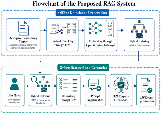
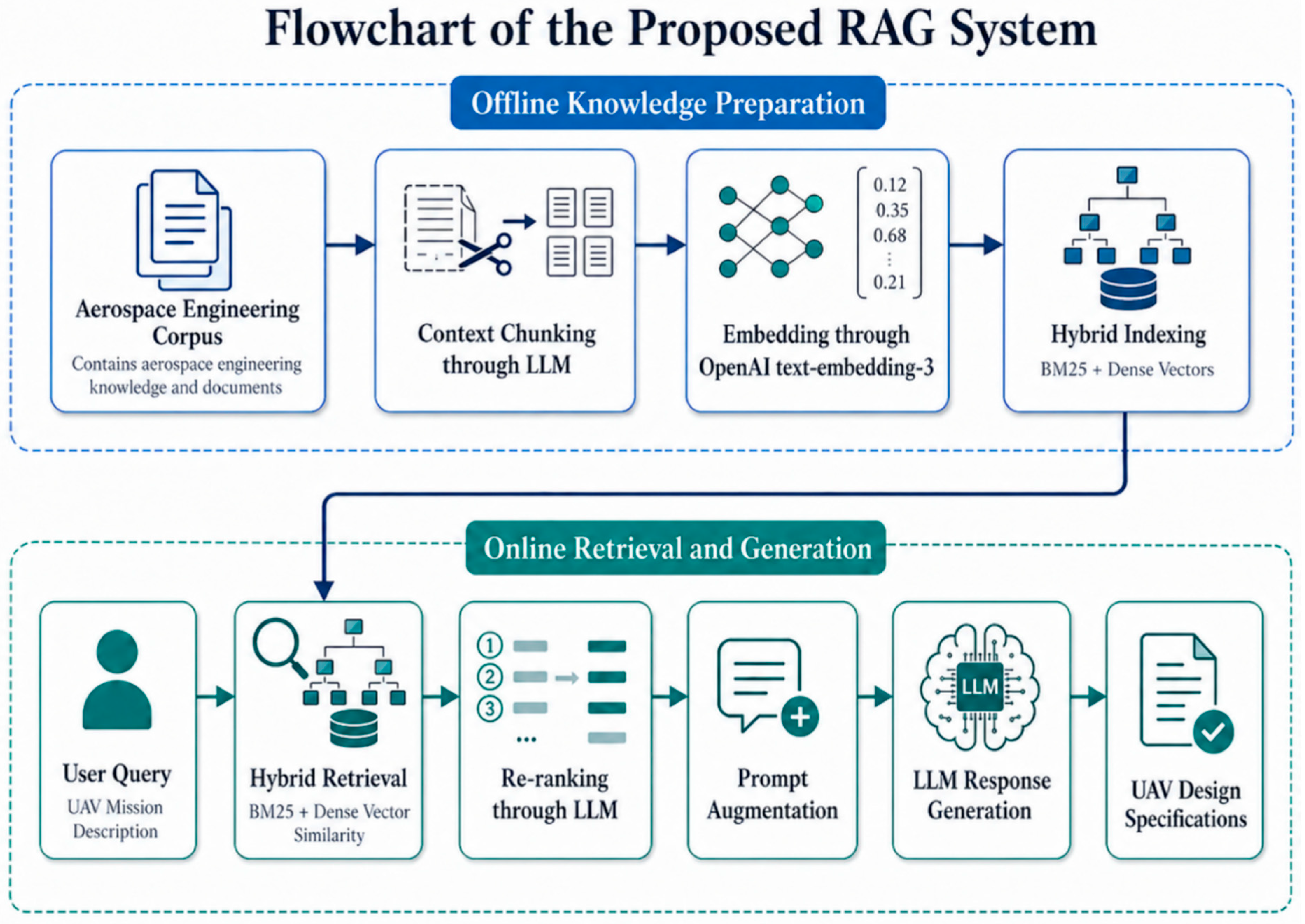
The overall retrieval-and-generation workflow used in this study is summarized in Figure 1. The flowchart highlights the two main stages: offline knowledge preparation, where the aerospace corpus is chunked, embedded, and indexed; and online retrieval-augmented generation, where the mission query is retrieved against the hybrid index, re-ranked, and injected into the final prompt to produce UAV design specifications.
Figure 1.
Flowchart of the proposed RAG system.
In this study, the RAG assessment was deliberately defined as a range-precision and traceability test rather than as a claim of final aerodynamic optimality. The objective was to show that a broad LLM-only design envelope could be narrowed into more precise, source-grounded sweep-angle intervals while still retaining preliminary physical feasibility. Therefore, the success criterion was not merely that RAG produced narrower numbers, but that a design instantiated inside those narrower intervals could pass the subsequent downstream feasibility gates. The CFD lift-versus-weight check and the nominal closed-loop 6-DoF response are used only as physics-based consistency checks: the narrowed RAG-derived ranges were sufficiently specific to guide CAD instantiation, yet not so restrictive that they eliminated a concept that remained feasible within the tested numerical domain.
2.2.1. Quantitative Assessment of RAG Range Precision and Evidence Alignment
To quantify the effect of retrieval grounding, the width of each proposed interval was calculated as the upper bound minus the lower bound. The range-reduction ratio (RRR) was then calculated as the percentage reduction in interval width from the LLM-only pass to the RAG-refined pass. This metric measures the precision gain achieved by evidence-grounded narrowing; it does not by itself claim aerodynamic optimality or probabilistic model certainty.
Across the three sweep variables, RAG reduced the total interval width from 25° to 7°, corresponding to a 72% aggregate reduction. The unweighted mean variable-level RRR was 70%. In addition, the three retained ranges passed all twelve applicable evidence checks: source authority, direct design relevance, operating-regime compatibility, and consistency with the CAD/control-surface/CFD assumptions. The resulting evidence-alignment coverage was therefore 12/12 (100%).
The literature comparison is intentionally framed as a consistency screen rather than as a universal numerical ground truth, because admissible sweep ranges depend on mission speed, payload volume, thickness distribution, planform segmentation, and tailless-control architecture. The relevant literature nevertheless supports the qualitative high-inboard, moderate-mid-panel, and lower-outer-panel sweep patterns summarized in Table 2. Consequently, the reported RRR and evidence-alignment coverage provide a quantitative and traceable assessment of the RAG contribution without overstating it as an independent expert-agreement score.
2.2.2. Structured Engineering Assessment of the Refined Sweep Ranges
To complement the deterministic range-precision metrics, the author team performed a structured engineering assessment of the retained sweep intervals summarized in Table 3. The assessment examined two perspectives: (i) aerodynamic and planform considerations and (ii) tailless-control and integration considerations. It assessed whether the cited evidence, mission constraints, and instantiated geometry jointly made each retained interval technically credible. It is not a formal independent external-expert panel, a universal aerodynamic optimization, or a substitute for higher-fidelity aerodynamic, structural, and flight-test validation.
Table 3.
Source traceability and structured engineering assessment of the RAG-refined segmented sweep-angle ranges.
Table 3 strengthens the evidence chain by distinguishing what the retrieved sources directly establish from what the RAG system subsequently synthesizes for the present configuration. The source material provides three numerical anchors: a 67° low-aspect-ratio leading-edge-sweep reference for the inboard region, a 70°/50° cranked-arrow precedent for the segmented mid-panel transition, and a 35-class moderate-sweep reference for the outer region. The structured engineering assessment treats the resulting 66–68°, 50–52°, and 32–35° intervals as technically coherent preliminary windows, while making clear that their precise boundaries are mission-specific RAG outputs subsequently checked for CAD compatibility rather than universal design rules. The later CFD lift, trim, static-margin, differential-elevon, and nominal 6-DoF results therefore remain the necessary downstream feasibility checks.
The present assessment is deterministic for the archived prompt, model settings, retrieval corpus, and source snapshot. It therefore quantifies interval precision and evidence coverage, rather than repeated-sampling variability. A future benchmark should repeat the LLM-only and RAG passes across multiple runs and independent expert panels to estimate output variance, agreement, and calibration against a broader set of validated UAV configurations.
2.3. Range-to-CAD Instantiation
A single design point was selected within the refined ranges using simple multi-attribute satisficing: priority to packaging and stability-friendly geometry while remaining within the RAG-constrained bands. The configuration was then parameterized and modeled in SolidWorks. Mass properties were computed from the assembled model, which returned a total mass of 1699 kg used to compute weight W = 16,661.5 N for the simulated condition.
For the whole-airframe coefficient normalization reported later, the CAD-derived gross blended lifting planform reference was set to S_ref = 18.66 m2. This integrated reference includes the horizontal blended wing-body lifting planform and excludes vertical fins. The measured tip-to-tip span was b = 4.9075 m, giving AR = b2/S_ref = 1.29. A piecewise-linear chord model using the five span stations (y, c) = {(0, 9.9336), (0.5041, 5.9007), (1.0047, 3.4755), (1.7047, 1.6853), (2.45375, 0.6104)} m yielded a provisional mean aerodynamic chord c_bar = 5.30 m when normalized by the adopted S_ref. These geometry references are used consistently for the present CFD coefficient post-processing.
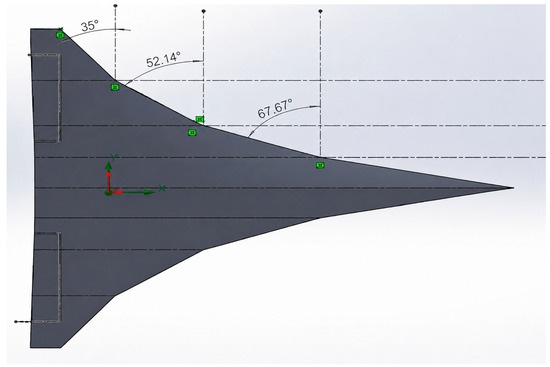
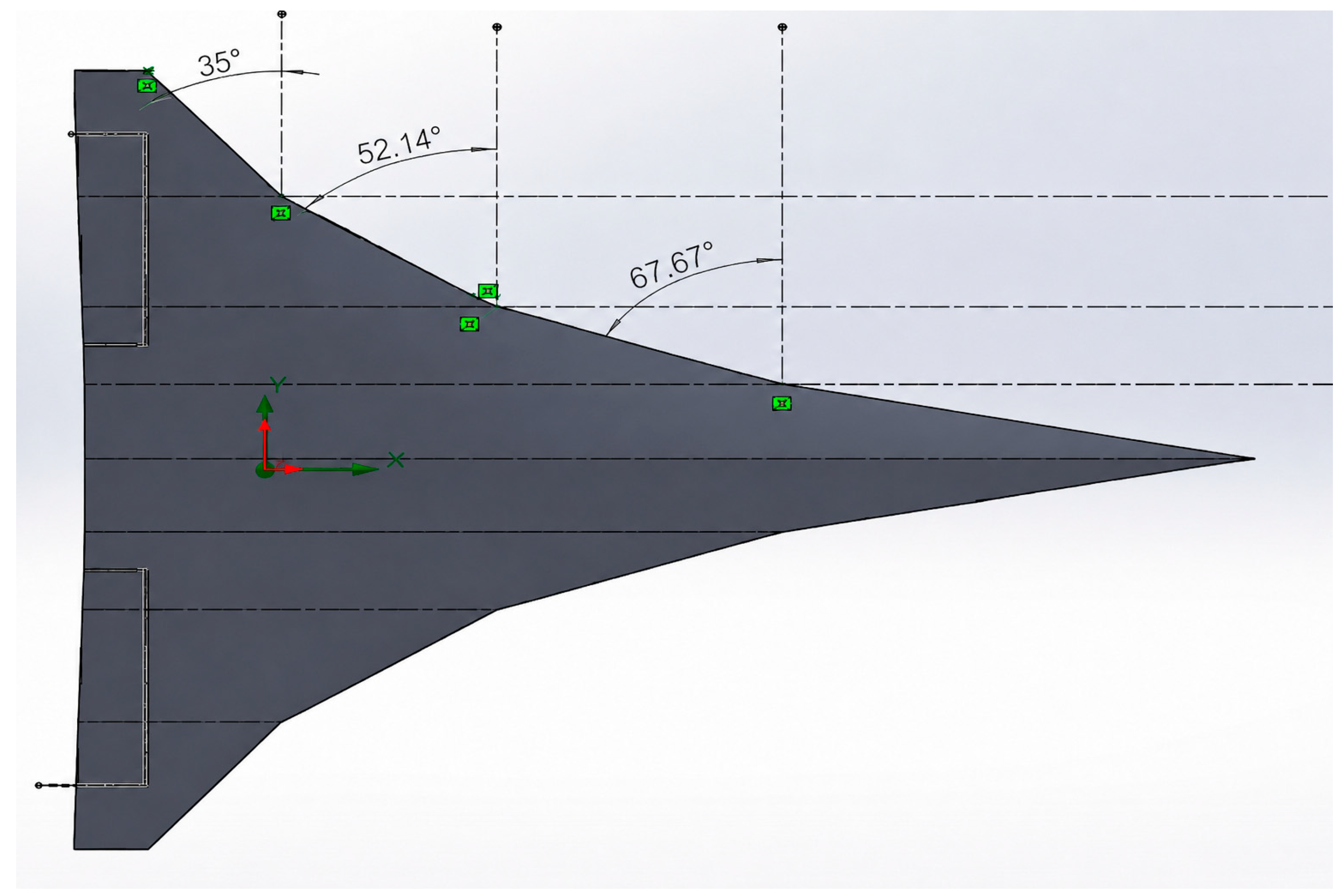
The realized CAD planform and its local sweep schedule are shown in Figure 2.
Figure 2.
Realized segmented-sweep geometry of the selected UAV planform, showing the local sweep schedule used in the CAD instantiation.
The realized planform (Figure 2) implements local leading-edge sweep angles of approximately 68° inboard, 52° at the mid-panel, and 35° at the outer panel (underlying CAD measurements: 67.7°, 52.1°, and 35.0°, respectively). Because the RAG intervals are reported to whole-degree precision, the CAD values are rounded to the nearest degree for the range comparison. The selected tailless configuration was therefore instantiated as a piecewise sweep schedule rather than as a single uniform-sweep wing. This clarifies how the broad mission-conditioned intervals proposed by the LLM and then narrowed by RAG were converted into a specific CAD geometry that balances aerodynamic shaping, internal packaging, and control-oriented geometric practicality.
2.4. CFD Parametric Experiment Design
A SolidWorks Flow Simulation parametric study was not limited to a simple angle-of-attack sweep. Instead, the aerodynamic database used in this extended work spans angle of attack α, sideslip angle β, and elevon-deflection states, so that the same LLM/RAG-derived airframe can be assessed both for static lift feasibility and for control-oriented simulation.
The study was configured as an external aerodynamic-flow analysis with air selected as the working gas, pressure set to 101,325 Pa, and temperature set to 293.2 K. The solver input used the aerodynamic-angles option, with the longitudinal plane defined as ZX and the longitudinal axis as X. The exported parametric-study files prescribe the freestream as a negative velocity because the incoming flow is imposed relative to the CAD model; in the analysis, the corresponding speed magnitude is used. Across the attached parametric workbooks, the aerodynamic database covers speed magnitudes of 50, 100, 150, 200, and 250 m/s, angles of attack α = {−8°, −4°, 0°, 4°, 8°, 12°, 18°}, and sideslip angles β = {−10°, −5°, 0°, 5°, 10°} for the neutral-elevon case. The control-effectiveness database further includes symmetric elevon cases with both elevons deflected up or down by 10°, 14°, and 20°, and differential cases in which the left and right elevons are deflected in opposite directions by the same magnitudes.
The flow regime is therefore subsonic over the tested grid. Using an ambient temperature of 293.2 K, the speed of sound is approximately 343 m/s; consequently, the tested CFD speed range approximately corresponds to M = 0.15–0.73, while the 120 m/s closed-loop mission reference corresponds to M ≈ 0.35. Using air at 101,325 Pa and 293.2 K, the density is approximately 1.20 kg/m3; the Reynolds number may therefore be reported as Re_c = ρVc/μ once the final CAD reference chord c is fixed. For transparency, the equivalent Reynolds-number range is approximately (3.3 × 10⁶ to 1.7 × 10⁷) × c when c is expressed in meters. The SolidWorks setup used the laminar-and-turbulent flow option. The resulting forces and moments are interpreted as preliminary engineering-level aerodynamic data for conceptual screening and controller lookup-table construction, not as certification-grade wind-tunnel-equivalent validation.
The baseline mesh used a manually specified global grid of Nx = 89, Ny = 64, and Nz = 55 basic cells. The local airframe mesh retained equidistant refinement around the lifting surfaces, leading edges, elevon regions, and wing tips, using the configured 0.05 m and 0.20 m refinement bands and a 0.10 m Close Thin Slots threshold; the local Advanced Refinement option was not activated. A separate cuboid wake-refinement region was retained downstream of the UAV. To provide a controlled numerical-resolution check, coarse, baseline, and fine global mesh levels were solved at a representative neutral-elevon condition while keeping the local airframe refinement, wake-refinement region, turbulence/solver settings, and aerodynamic boundary conditions unchanged. The comparison is reported as a three-level mesh-resolution consistency assessment rather than as a formal grid-convergence-index or mesh-independence demonstration.
2.5. Static Lift Feasibility Criterion
For each AoA, forces from the realizations were averaged after conversion from the CAD-aligned force components to wind-axis lift and drag. Because the SolidWorks parametric export applies the freestream relative to the stationary CAD model, the physical incidence used in post-processing was α = −α_table. With X = F_x and Z = F_z in the adopted longitudinal/vertical axes, the transformed forces were L = F_x sin α − F_z cos α and D = −(F_x cos α + F_z sin α). Thus, at α = 0°, L = −F_z and D = −F_x, F_y is a side-force component and was not treated as lift. The feasibility metric is L/W. The decision rule remains binary and conservative: a condition is lift-feasible when a non-zero AoA interval exists for which L ≥ W at the simulated condition. We report the first L = W crossing and the growth of L/W beyond it. No reference-area normalization is required for this absolute-force gate.
For coefficient, trim, elevon-authority, and local static-stability post-processing, the same gross reference geometry was used throughout: S_ref = 18.66 m2, c_bar = 5.30 m, and CG-referenced pitching moment M_y. With q∞ = 0.5ρV2, the normalized quantities are C_L = L/(q∞S_ref), C_D = D/(q∞S_ref), C_m = M_y/(q∞S_ref c_bar), and L/D = L/D. A static trim point must satisfy both L − W = 0 and M_y = 0. The local static-margin proxy was calculated only from the neutral-elevon, β = 0° CFD slice as SM = −C_mα/C_Lα. Accordingly, the resulting coefficients and stability quantities are interpreted as bounded, CFD-based preliminary estimates rather than certification-level aerodynamic data.
2.6. Qualitative CFD Flow-Visualization Assessment
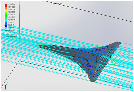
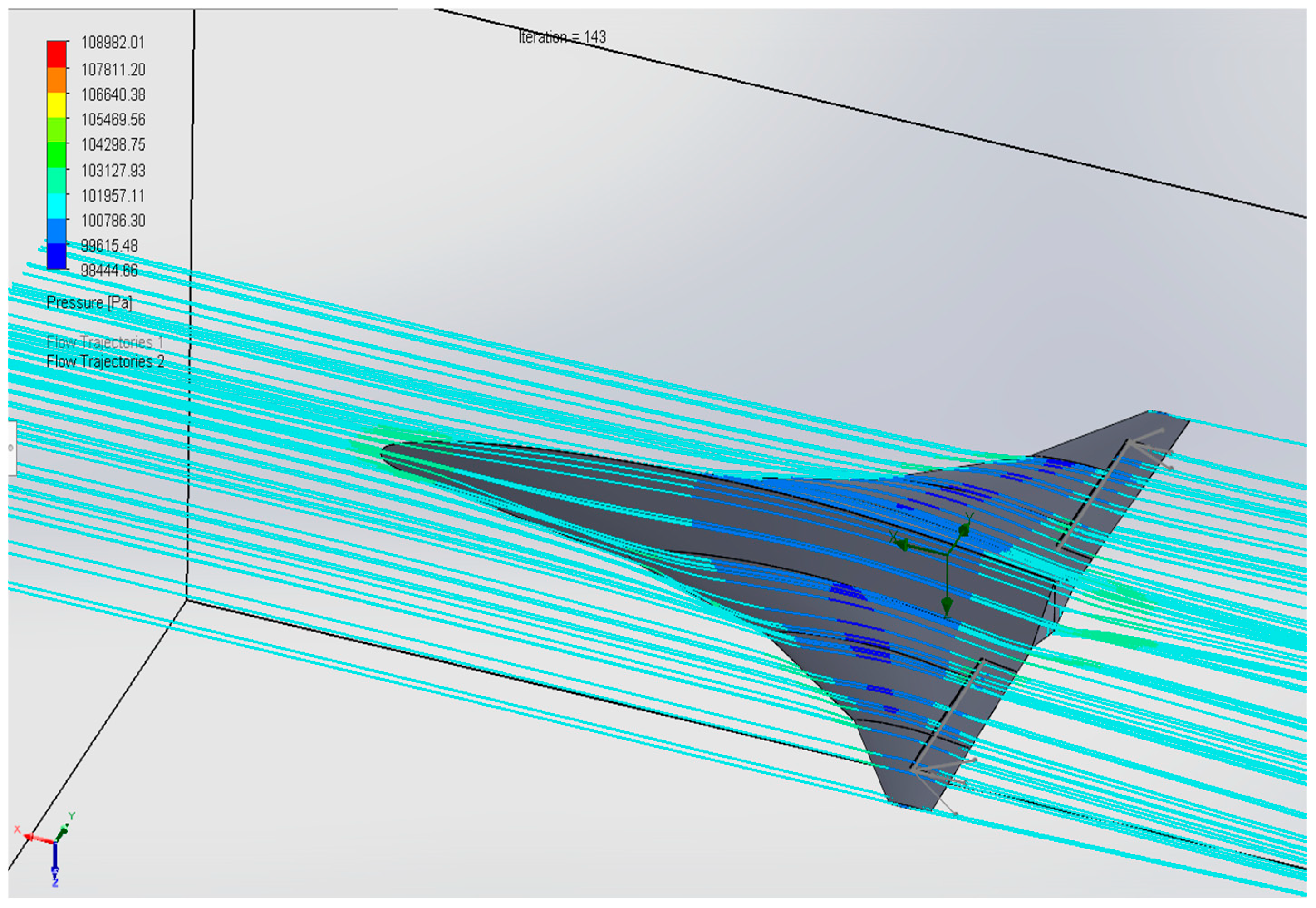
Beyond absolute force comparison, we also examined CFD pressure and streamline visualizations at the selected cruise condition. The objective was qualitative rather than coefficient-based: to verify that the upper-surface pressure field is dominated by low-pressure regions and that the streamlines remain largely coherent around the blended wing-body planform. This visualization does not replace the force-based feasibility witness, but it provides an additional check that the LLM/RAG-derived geometry produces a physically plausible flow organization consistent with classical pressure-difference mechanisms of lift generation [22].
2.7. Closed-Loop 6-DoF Nominal Feasibility-Assessment Setup
To assess whether the same airframe is dynamically manageable after the static CFD gate, the geometry was embedded in a closed-loop six-degree-of-freedom simulation environment. The nominal feasibility-assessment mission was approximately 32 km long at a nominal speed of 120 m/s. The commanded lateral path displaced the vehicle from 0 m to 50 m and back to 0 m, while the altitude command varied from 100 m to 120 m before returning to 100 m. This experiment was deliberately designed as a single mission-level consistency and feasibility check, rather than as a certification-level validation, disturbance-rejection study, or robustness campaign.
The reported run used a predictor-based line-hold lateral controller. Its structure is nevertheless academically consistent with established nonlinear/look-ahead UAV path-following principles [41]. The controller computes the cross-track error relative to the active path segment and combines it with a bounded prediction term based on cross-track velocity. The effective look-ahead time is segment-aware, limited near waypoint transitions, and protected by a terminal-capture rule so that the controller does not become too passive near the end of the path.
The predicted lateral error is then converted directly into a differential-elevon command through a deadband and mild/strong correction logic. In the final wrapper, the principal lateral settings were a cross-track deadband of 8 m, a far-error threshold of 35 m, an effective look-ahead range of 20–100 s, a cross-track-rate limit of 2 m/s, a prediction-term limit of 120 m, and a final predicted-error limit of 200 m. Under the adopted sign convention, the final mild/strong differential commands were +0.7725/+1.2000 deg for one correction direction and −0.4725/−0.7725 deg for the opposite direction, around a differential trim of +0.1150 deg.
The longitudinal channel used a TECS-lite correction layer to regulate path-referenced altitude and speed. This layer follows the energy-management motivation of fixed-wing TECS approaches [18,19], but it was implemented here as a simplified feasibility controller rather than as a full certified TECS autopilot. The path-referenced down-position error, vertical speed, and speed error were mapped to symmetric-elevon and throttle corrections. In the final configuration, the main symmetric-elevon gains were 0.120 deg/m for altitude error, 0.800 deg/(m/s) for vertical-speed correction, and 0.030 deg/(m/s) for speed-error relief, with the speed reference set to 120 m/s.
The inner-loop/control-allocation layer mixed the longitudinal and lateral commands into the available tailless-aircraft effectors: left elevon, right elevon, and throttle. The symmetric elevon component primarily supported altitude/path-height regulation, while the differential component primarily supported lateral line holding. The individual elevon commands were obtained by adding and subtracting half of the differential command from the symmetric command, then enforcing the same physical deflection limits represented in the CFD database, namely approximately −20 deg to +20 deg. The throttle command was also bounded within the configured normalized range. This use of limited elevon allocation is compatible with flying-wing/tailless control-allocation literature [16,17] and with effectiveness-aware fixed-wing control research [20,21].
The closed-loop simulation model used a rigid-body six-degree-of-freedom Newton-Euler formulation with translational velocity, angular velocity, quaternion attitude, and local NED position states. The body-frame convention was x forward, y right, and z down. Gravity was included in the body-frame acceleration equation, and mass/inertia properties were imported from the SolidWorks mass-property model used for the same CAD geometry. Aerodynamic forces and moments were assembled from the SolidWorks Flow Simulation parametric exports into lookup tables over speed, angle of attack, sideslip, symmetric elevon deflection, and differential elevon deflection. Interpolation was used inside the tabulated envelope, while commands and states were saturated at lookup-table limits to avoid unsupported aerodynamic extrapolation.
The nominal run was initialized at the reference mission speed of 120 m/s, near-level attitude, zero initial angular rates, and an initial altitude of approximately 100 m. The controller parameters were fixed before the reported run; no post hoc gain tuning was performed to improve the displayed trajectory after observing the response. The outputs used for assessment were 3D trajectory, top-view corridor tracking, cross-track error, altitude-path error, speed tracking, attitude excursions, elevon commands, throttle command, and absence of divergence or sustained actuator saturation.
This closed-loop assessment is therefore framed as a nominal dynamic-feasibility witness. It shows that the CFD-derived aerodynamic lookup table and the predictor-based line-hold/TECS-lite controller can keep the preliminary geometry bounded during a representative mission. It is not presented as a complete robustness proof. Future robustness tests should include controller-gain sweeps, wind/gust disturbances, actuator-rate limits, sensor noise and bias, mass/inertia perturbations, and off-nominal initial-condition tests before any certification-oriented claim is made.
2.8. Reproducibility and Traceability
All prompts (initial and RAG-augmented), LLM settings, retrieval hits, and solver versions/flags were archived. To assess whether the workflow was not limited to the primary high-speed cargo mission, and although the primary cargo-UAV case followed the full sequence from mission encoding to closed-loop 6-DoF validation, the supplementary ISR case repeated the LLM → RAG → CAD → static-feasibility part of the workflow to test whether the range-generation and lift-feasibility logic transferred beyond the primary mission.
For the primary sweep-angle comparison, the archived run also records the LLM-only and RAG-refined interval widths, the resulting RRR values, and the four evidence-screen outcomes per design variable reported in Table 2. This enables independent reconstruction of the reported range-precision and evidence-alignment metrics from the preserved prompt and corpus snapshot.
2.9. Comparator: Traditional Conceptual Design vs. LLM + RAG Front End
Traditional conceptual aircraft design typically begins with expert interpretation of the mission requirements, followed by preliminary sizing, early aerodynamic and structural trade-offs, and progressive narrowing toward a small number of candidate configurations. This process is rigorous and remains essential for certification-oriented development, but it is also expert-dependent, time-intensive, and often limited in the number of design alternatives that can be explored during the earliest conceptual phase.
In contrast, the proposed LLM + RAG front end is intended as an upstream support layer rather than a replacement for conventional design practice. It can convert narrative mission descriptions into structured preliminary parameter ranges, including sweep angles, taper ratio, thickness-to-chord values, incidence or twist assumptions, control-surface concepts, and volumetric constraints. The RAG stage grounds these suggestions in retrieved aerospace literature, requires explicit assumptions and units, and provides traceable evidence for each proposed range. This allows multiple mission-consistent design envelopes to be generated rapidly while maintaining a clearer provenance trail than an unconstrained LLM-only response.
Both workflows ultimately remain subject to the same downstream engineering checks. In the present study, the LLM + RAG-derived design candidates are not accepted directly; they are passed to CAD instantiation, CFD evaluation, and a conservative lift-versus-weight feasibility gate. Therefore, the comparison is not between an automated method and a traditional method as competing final design processes, but between two ways of producing early-stage candidate envelopes for subsequent physics-based validation. The LLM + RAG front end is most useful when requirements are still fluid, rapid exploration is valuable, and traceable design rationale is needed. Traditional conceptual design remains the primary reference path once requirements are fixed, higher-fidelity sizing is required, or certification-critical decisions must be made.
3. Results and Discussion
3.1. Static CFD Dataset and Weight Reference
Mass properties were read from the CAD assembly: mass m = 1699 kg, giving weight W = mg = 16,661.5 N (with g = 9.80665 m s−2). Reported density and volume reflect solid-model assumptions and are not used as aerodynamic references. Aerodynamic forces were exported from the broader SolidWorks Flow Simulation database spanning angle of attack, sideslip, and elevon-deflection cases. For the static feasibility results reported here, we restricted analysis to the neutral-elevon subset with ∣β∣ ≤ 1°, yielding realizations per AoA at α ∈ {−8°, −4°, 0°, 4°, 8°, 12°, 18°}.
3.2. Static Lift Feasibility: Vertical Force vs. AoA (β ≈ 0°)
Table 4 summarizes the mean L and L/W. These features demonstrate a non-zero AoA interval satisfying L ≥ W under the tested flow condition.
Table 4.
Mean lift-supporting aerodynamic force after wind-axis transformation for the neutral-elevon, near-zero-sideslip CFD slice.
3.3. Static Feasibility Interpretation
The feasibility assessment is based on a direct comparison between the CAD-derived aircraft weight and the CFD-reported lift-supporting force at the same freestream condition:
L(α) ≥ W
No reference area or dynamic-pressure normalization is required here because the criterion is expressed in absolute force. The conservative feasibility check is performed on the neutral-elevon, near-zero-sideslip slice:
β ≈ 0°
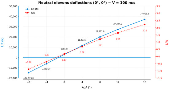
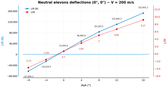
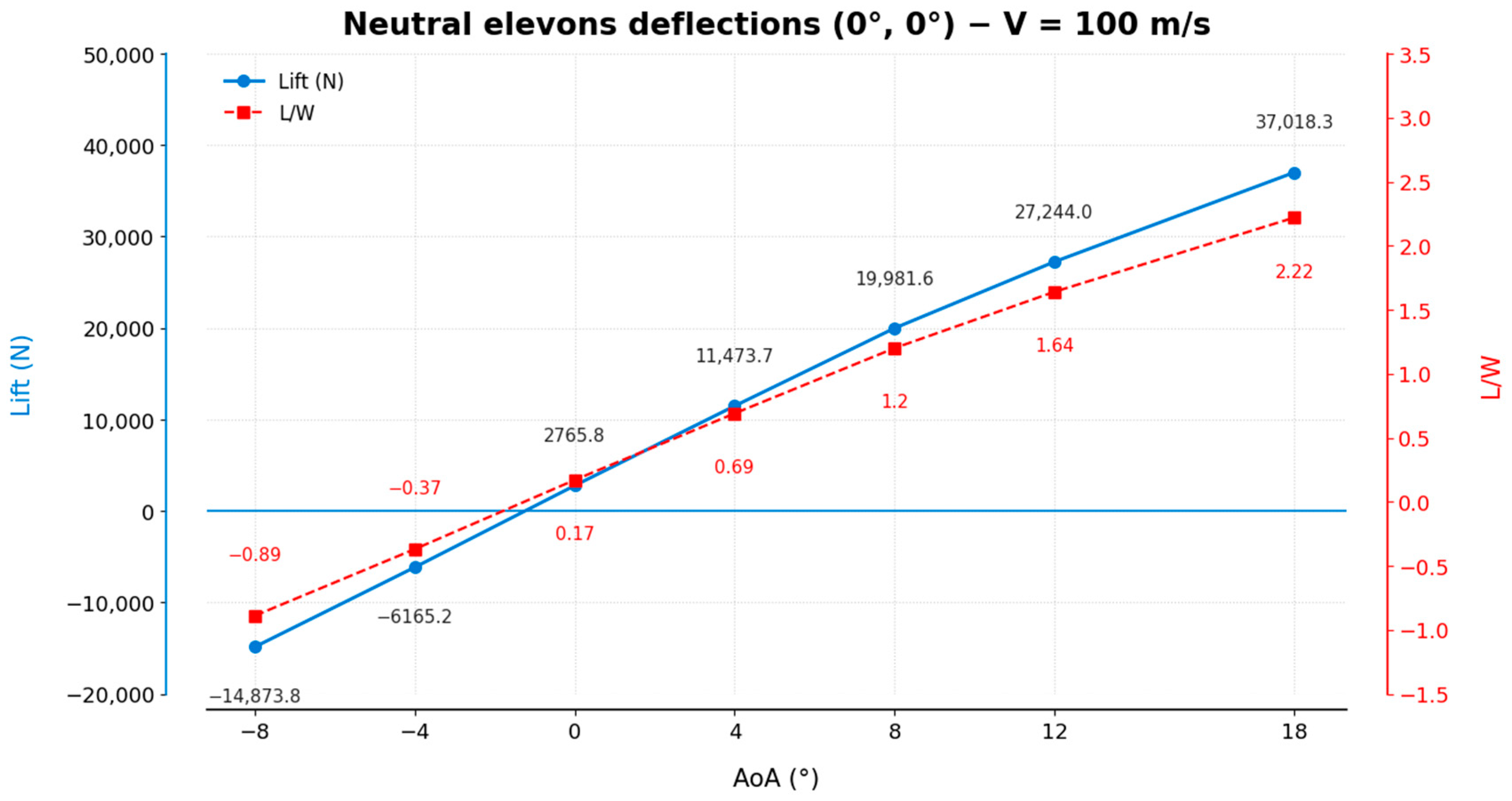
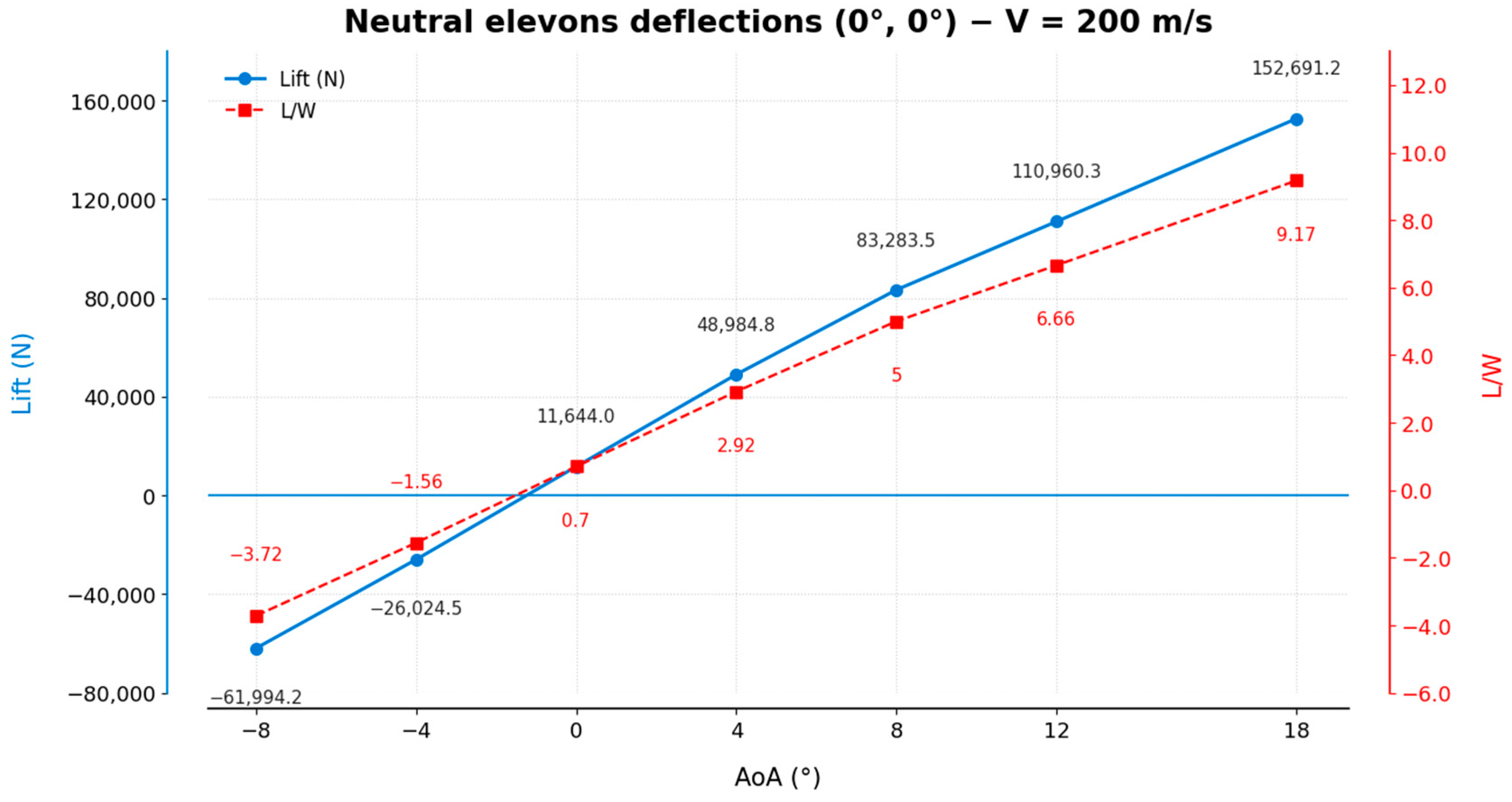
The CFD results (Figure 3) show a consistent increase of lift with angle of attack. At V = 100 m/s, the lift-to-weight ratio crosses unity between 4° and 8°. At V = 200 m/s, the crossing occurs earlier, between 0° and 4°. Thus, the selected geometry produces a repeatable lift-supporting trend across the tested speed range, while the exact crossing angle depends on freestream velocity. These results are interpreted as a preliminary lift-feasibility witness, not as a complete aerodynamic certification.
Figure 3.
Static lift feasibility for the neutral-elevon configuration at 100 m/s and 200 m/s.
3.4. Coefficient, Trim, Elevon-Authority, and Local Static-Stability Results
The absolute force results in Table 4 establish a lift-supporting condition, but they do not by themselves quantify drag, trim, or static stability. Accordingly, the neutral-elevon, β = 0° CFD slice was post-processed using wind-axis transformation and the CG-referenced M_y defined in Section 2.5. Table 5 summarizes the reference convention used consistently for all coefficients and moment normalizations.
Table 5.
CAD-derived reference geometry and coefficient convention used for CFD post-processing.
The physical angle of attack was taken as α = −α_table. Using q∞ = 0.5ρV2, the reported coefficients were C_L = L/(q∞S_ref), C_D = D/(q∞S_ref), and C_m = M_y/(q∞S_ref c_bar). For the local linearized longitudinal assessment, C_Lα and C_mα were extracted by least-squares fitting over −4° ≤ α ≤ +8°. A positive value of SM = −C_mα/C_Lα indicates a locally restoring pitch-moment slope under the adopted CG and sign convention. The resulting longitudinal slope estimates and static-margin proxies are summarized in Table 6.
Table 6.
Local neutral-elevon, β = 0° longitudinal slope estimates from the CFD force/moment exports.
Across the tested 100–200 m/s conditions, C_Lα > 0 and C_mα < 0. The resulting 8.15–8.55% c_bar values are therefore reported as local CFD-derived static-margin proxies. They provide preliminary evidence of positive longitudinal static stability near the analyzed incidence range, but they are not presented as a full-envelope neutral-point determination or as mesh-independent certification evidence.
Static trim was calculated by piecewise-linear interpolation across the actual symmetric-elevon grid, with simultaneous residual conditions L − W = 0 and M_y = 0. The positive symmetric-deflection direction in Table 7 is defined as the exported Both-UP elevon configuration. At 100 m/s, no simultaneous trim solution was found inside the tested α and ±20° symmetric-elevon bounds; this result is retained rather than extrapolated.
Table 7.
Piecewise-linear trim and near-trim elevon-effectiveness results derived from the CFD grids.
These coefficient, trim, and control-effectiveness calculations strengthen the aerodynamic evidence chain from the LLM + RAG-derived geometry to the CFD lookup table and nominal 6-DoF mission. They remain preliminary because the study has not yet established grid-convergence-index bounds, a full nonlinear trim envelope, actuator-rate effects, structural margins, wind-tunnel correlation, or robustness under disturbances and model uncertainty.
3.5. Three-Level Mesh-Resolution Consistency Assessment
A controlled three-level mesh-resolution assessment was performed at V = 200 m/s, α = 4°, β = 0°, and with neutral elevons. Only the prescribed global mesh density was varied between the coarse, baseline, and fine cases; the local airframe mesh, wake-refinement zone, solver/turbulence settings, and operating condition were held unchanged. Table 8 reports the wind-axis force and CG-referenced pitching-moment outputs and the corresponding coefficients using the common reference convention of Section 3.4.
Table 8.
Three-level mesh-resolution consistency assessment at V = 200 m/s, α = 4°, β = 0°, and with neutral elevons.
Relative to the fine-mesh values, the baseline-to-fine changes were 7.4% for C_L, 2.5% for C_D, and 12.1% for C_m. The lift-to-weight ratio remained well above unity in every case (2.86–3.17), the transformed drag remained positive, and the CG-referenced pitching moment remained negative under the adopted convention. Thus, the three grids preserve the absolute lift-feasibility interpretation and the pitch-moment sign at the representative operating point. The test does not establish mesh independence, and it does not validate the full C_mα slope or static-margin estimate across the full incidence range. Accordingly, the coefficient, trim, and local static-stability quantities in Section 3.4 are retained as preliminary engineering-level estimates.
3.6. Qualitative CFD Pressure and Streamline Assessment
Figure 4 shows the CFD-based pressure distribution and flow trajectories around the proposed UAV at the selected cruise condition. The upper surface of the blended wing-body geometry is dominated by blue and cyan contours, indicating comparatively low pressure over the main lifting surfaces. Qualitatively, this is consistent with lift generation because it suggests a favorable pressure difference between the upper and lower sides of the airframe [22]. In addition, the streamlines remain largely coherent and aligned with the freestream as they pass over the fuselage and wing planform, without obvious large-scale breakdown under the examined condition. Therefore, this visualization complements Figure 3 by providing qualitative aerodynamic evidence that the LLM/RAG-assisted geometry is not only numerically lift-capable, but also aerodynamically plausible at the inspected operating point.
Figure 4.
CFD-based pressure distribution and flow trajectories around the proposed UAV at the selected cruise condition, used as a qualitative flow-plausibility check rather than as a substitute for force-based validation.
3.7. Closed-Loop 6-DoF Nominal Feasibility Assessment
To complement the static aerodynamic feasibility gate reported above, a closed-loop nominal feasibility assessment was conducted on the same LLM + RAG-derived UAV geometry. The purpose was not to replace formal static-stability, trim, controllability, or robustness analysis, but to determine whether the simulated airframe response could remain bounded during one representative nominal mission-like trajectory. This additional step therefore checks whether the generated concept is compatible with the available CFD-derived force/moment lookup domain and bounded control allocation under the reported conditions [18,19,20,21]. It is not a flight-validation or controller-qualification experiment.
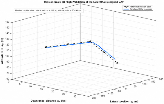
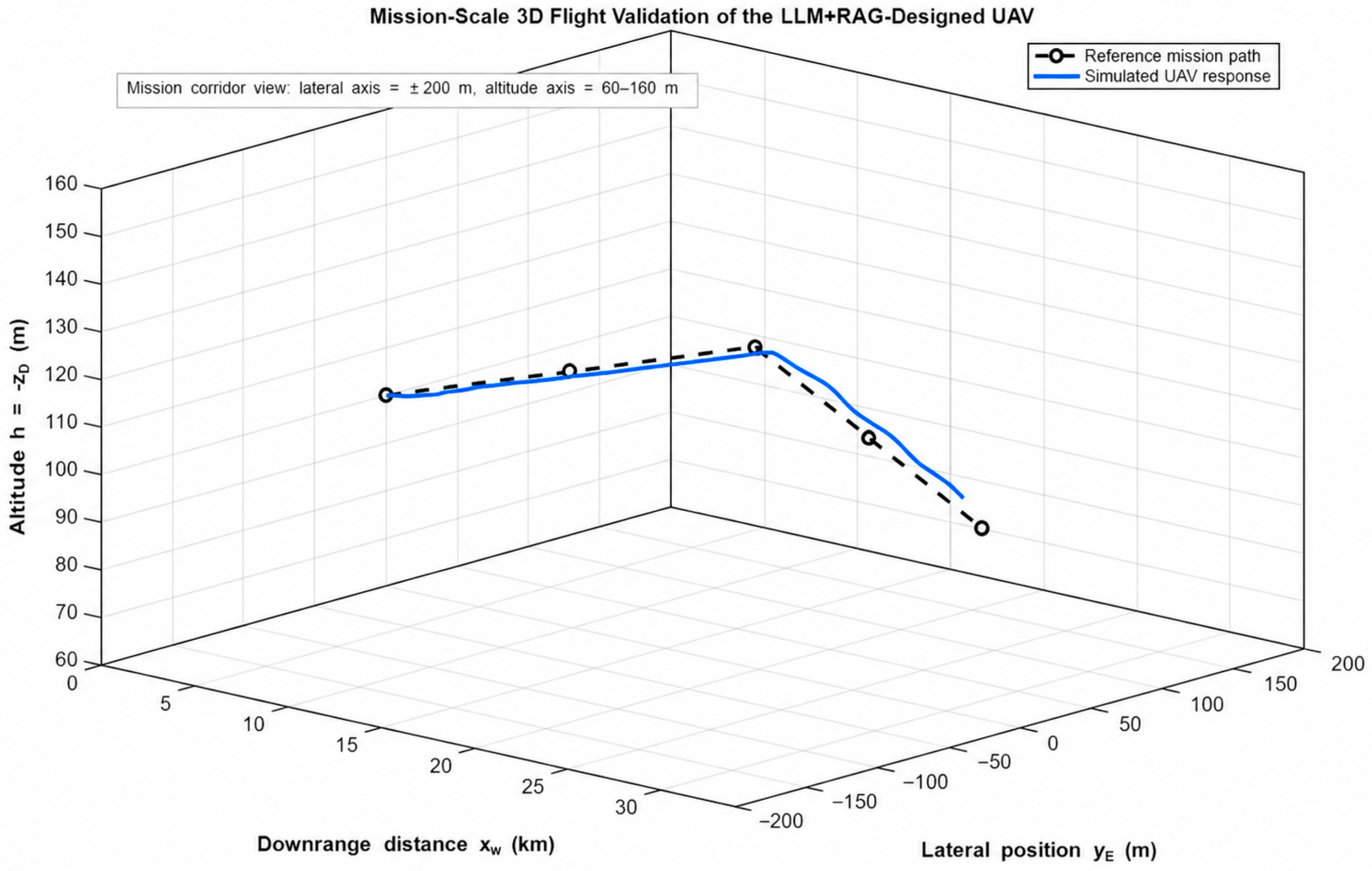
Figure 5 presents the three-dimensional trajectory response on mission-scale axes. The simulated UAV closely follows the commanded route and remains within the intended operational corridor throughout the climb-cruise-descent sequence. The broad display axes are deliberate: the goal is to evaluate mission-level feasibility rather than magnify small deviations. Across the approximately 32 km scenario, the vehicle completes the maneuver without divergence, loss of speed control, or excessive lateral departure from the commanded path.
Figure 5.
Closed-loop 3D nominal mission-feasibility assessment of the LLM + RAG-derived UAV. The simulated vehicle follows a mission-scale 3D trajectory with lateral displacement and altitude variation from 100 m to 120 m and back to 100 m.
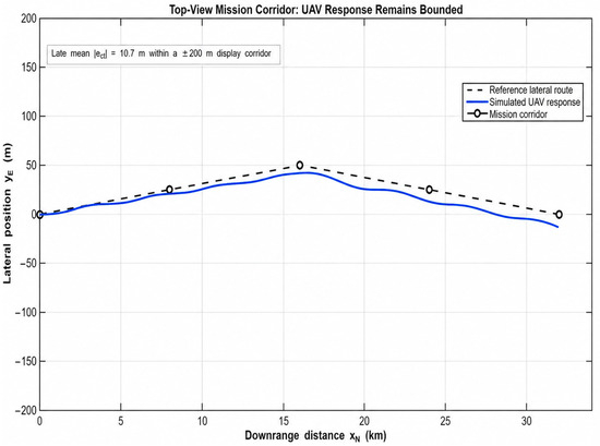
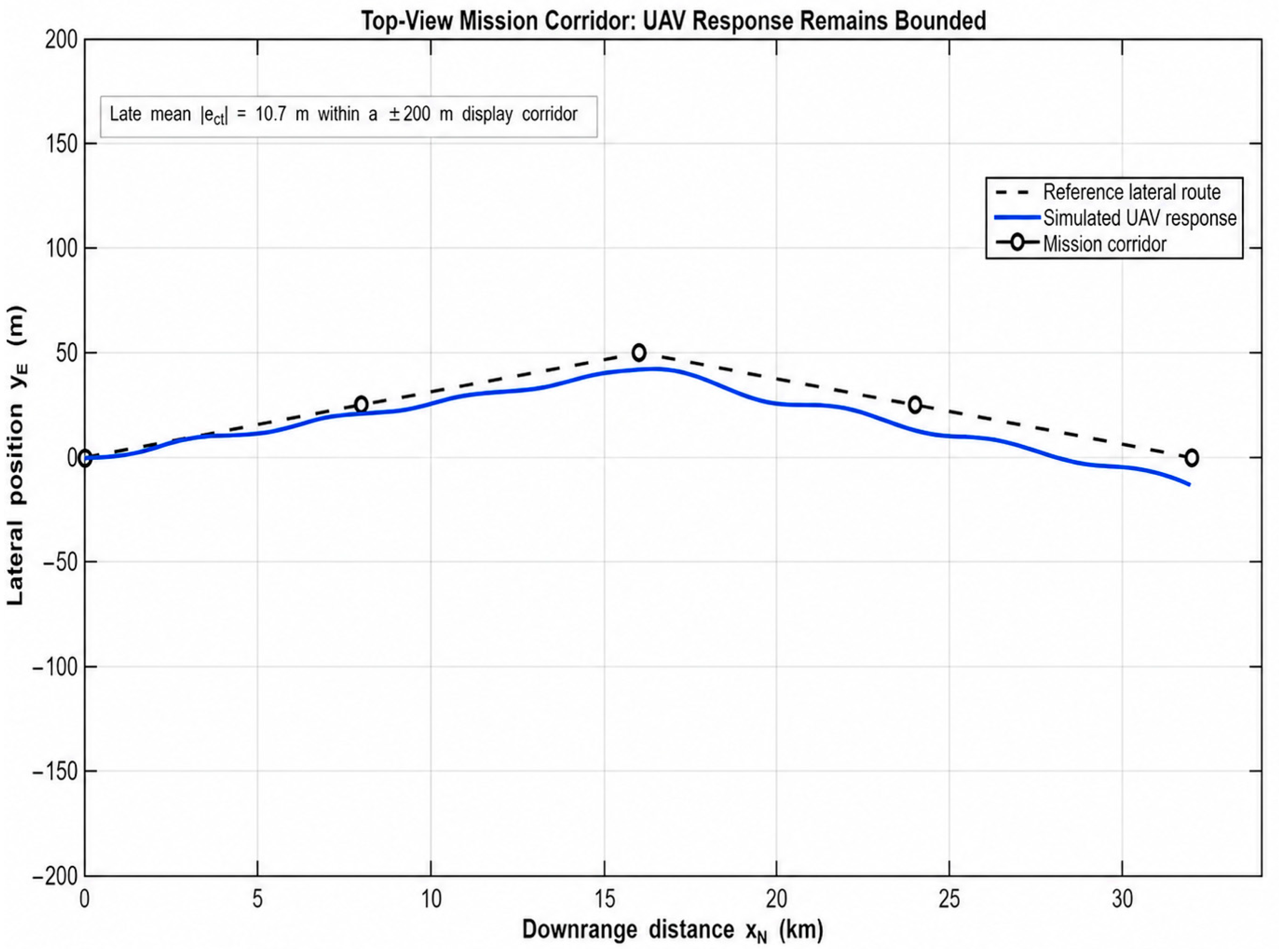
Figure 6 shows the same motion from a top-view perspective. The UAV remains inside a ±200 m lateral mission corridor while executing the commanded lateral displacement. The late mean cross-track error is approximately 10.7 m, which is small relative to both the mission length and the displayed corridor width. This supports the interpretation that the configuration can perform smooth lateral shaping despite relying on differential elevon action rather than conventional rudder-based yaw control.
Figure 6.
Top-view mission corridor tracking. The UAV remains inside the ±200 m lateral corridor while following the commanded route.
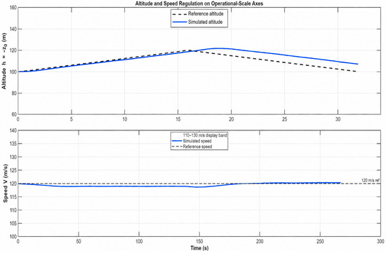
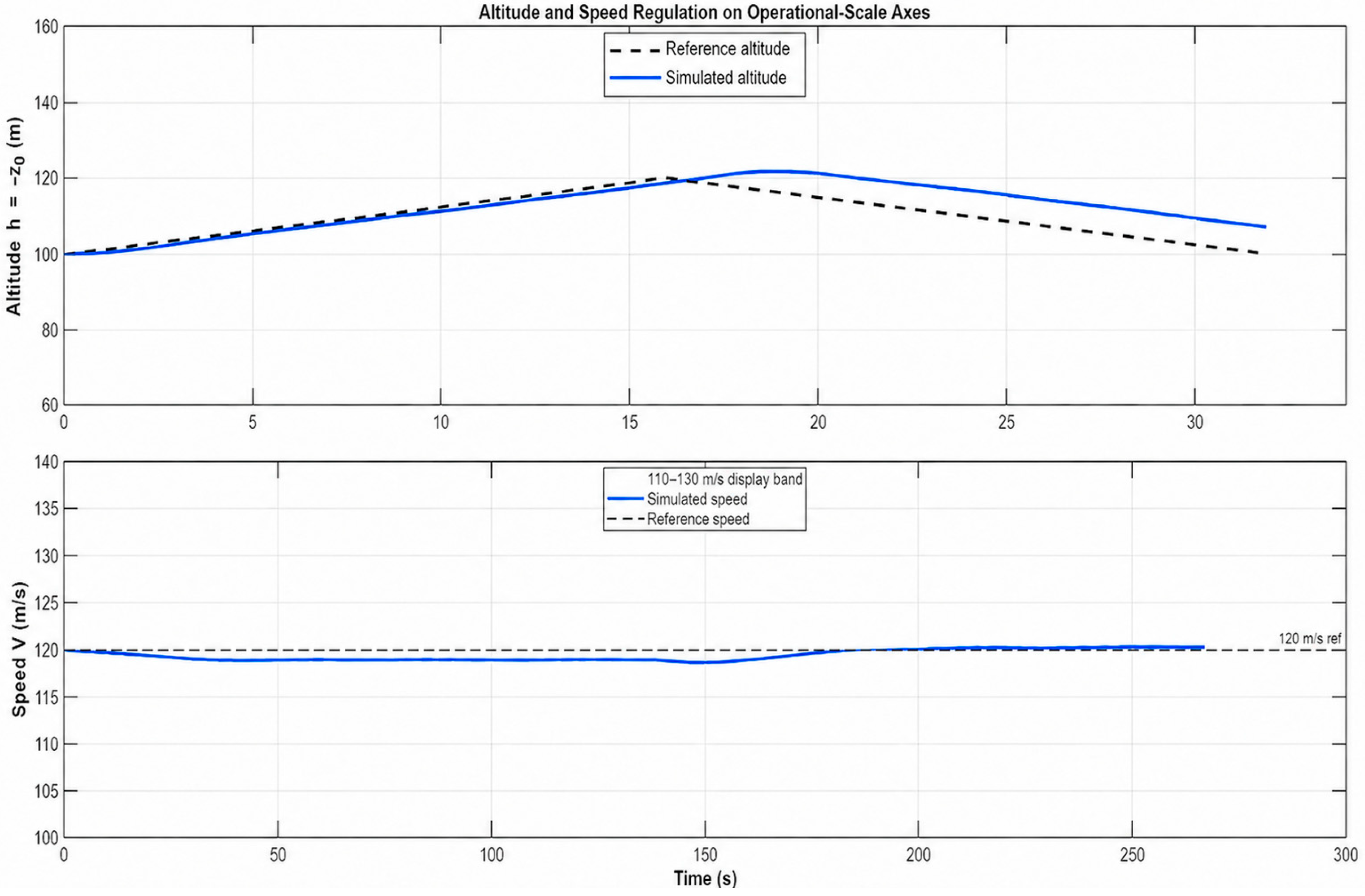
Figure 7 reports altitude and speed regulation using operational-scale axes. The altitude response follows the commanded 100–120–100 m profile with a late mean altitude-path error of approximately 7 m. At the same time, speed remains close to the 120 m/s reference throughout the maneuver, indicating that the TECS-lite layer manages the coupling between altitude, speed, and control effort during the 3D mission.
Figure 7.
Altitude and speed regulation on operational-scale axes. The aircraft follows the commanded altitude schedule while maintaining speed close to the 120 m/s reference.
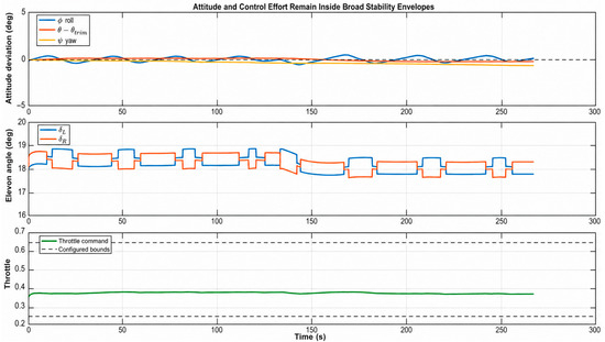
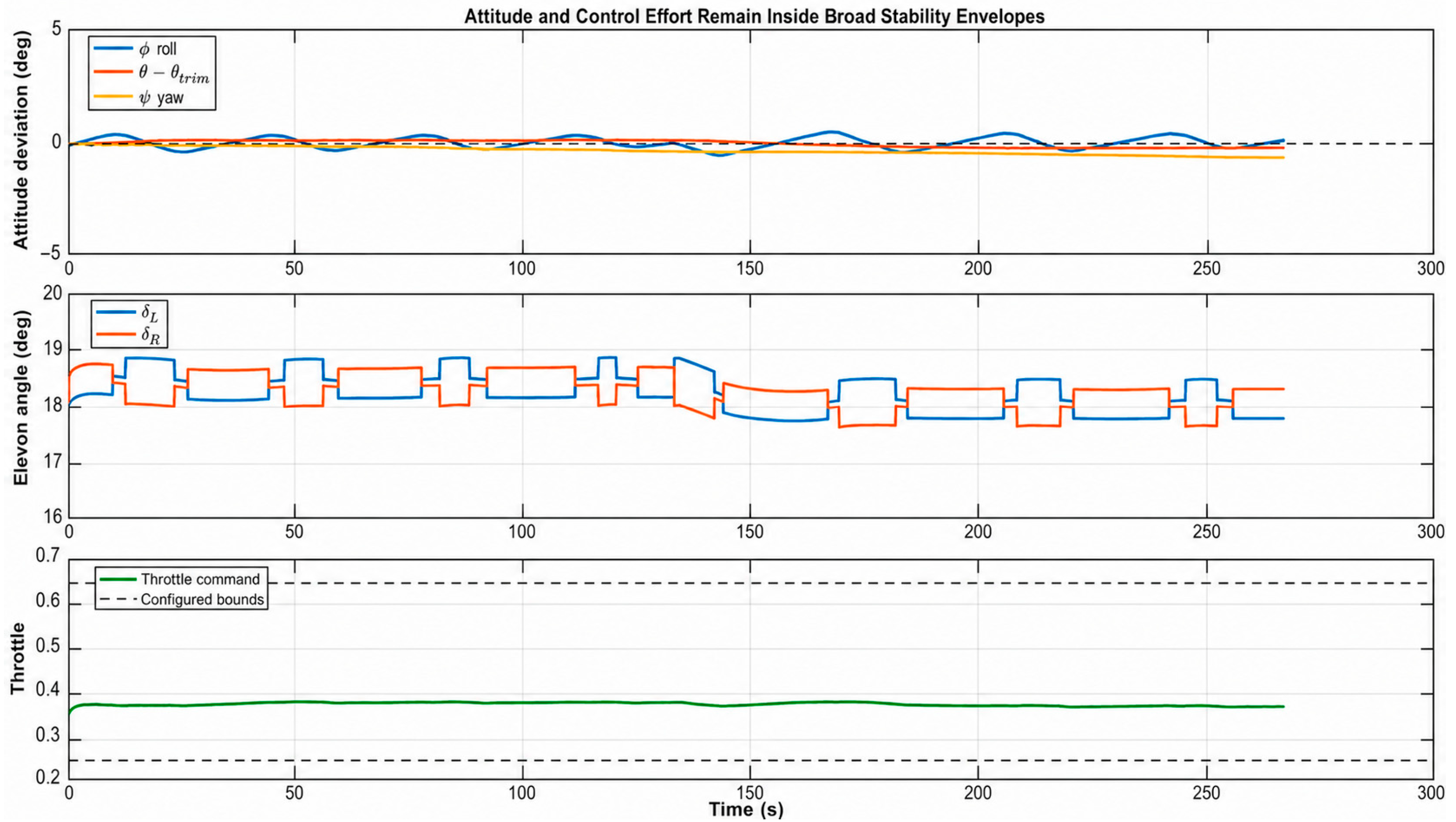
Figure 8 illustrates attitude and control-effort histories. Roll, yaw, and pitch deviations remain bounded within the selected ±5° display envelope. The left and right elevon commands and throttle remain within the imposed lookup-table limits; however, the sustained positive symmetric-elevon bias operates close to the upper deflection limit. The trajectory is therefore achieved with bounded control activity, while trim margin and actuator authority remain items for subsequent aerodynamic and controller refinement.
Figure 8.
Nominal attitude and control histories during the closed-loop feasibility run. Attitude remains bounded and the effector commands remain within the imposed lookup-table limits.
Overall, the nominal dynamic assessment functions as a second feasibility gate without replacing formal trim, static-stability, or controller-robustness analysis. The initial CFD analysis established that the airframe can generate a lift-supporting force over a non-zero angle-of-attack interval, while the nominal closed-loop mission shows that the same lookup-table model can be guided through one representative 6-DoF maneuver with bounded lateral motion, altitude regulation, speed tracking, attitude excursions, and acceptable actuator demand. Thus, the LLM + RAG pipeline yields a control-relevant preliminary candidate for higher-fidelity simulation and subsequent optimization, rather than a statically validated, robustly qualified, flight-ready, or certification-ready aircraft.
3.8. Supplementary Mission Generalization Study
To test generalization beyond the primary case, we applied the same LLM→LLM + RAG workflow to a new endurance-first coastal ISR mission (M 0.30–0.40 @ ~2 km, ≤2 g, gust-tolerant) constrained to a single-sweep trapezoidal flying wing. Pass 1 (LLM-only) produced broad, mission-consistent ranges (sweep 20–28°; AR 6.5–8.5) with medium confidence. Pass 2 (LLM + RAG) then narrowed these to sweep 22–26°; AR 7.0–8.0, citing low-Mach stall behavior of mildly swept wings, gust/aeroelastic penalties for very high AR, and the stabilizing role of moderate taper plus washout. We instantiated a simple design inside the refined bands (LE sweep 24°, AR 7.4, λ = 0.50, 3° washout, 2.5° dihedral, reflex airfoils; elevons 65% semi-span), and ran the same conservative binary feasibility witness used in the main study (compare L(α) vs. W at β ≈ 0°). Lift crossed weight by α ≈ 6° and grew monotonically thereafter, mirroring the qualitative pattern in the primary results. This second mission therefore replicates our research’s core claim: LLMs provide a reasonable mission-conditioned envelope, RAG tightens it with literature-backed justifications, and a concrete design chosen within the narrowed bands passes a minimal aerodynamic feasibility check.
4. Limitations and Future Work
The study is therefore presented as a transparent conceptual-feasibility assessment that prepares a generated concept for later high-fidelity CFD, wind-tunnel testing, systematic controller tuning, and formal robustness analysis. The scope deliberately stops before any flight-ready or certification-oriented conclusion. CG-referenced coefficient post-processing, static-trim interpolation, local static-margin proxies, and elevon-effectiveness estimates were added; however, they remain conditional on the adopted reference geometry, the selected CFD modeling assumptions, and the baseline aerodynamic database. The added three-level mesh-resolution consistency assessment preserves the qualitative lift, drag, and pitch-moment-sign interpretation, but the observed pitching-moment variation means that no mesh-independent coefficient, static-margin, neutral-point, robust-control, or flight-readiness claim has been made.
Future work will build on the present workflow by coupling LLM-based proposal generation with multi-fidelity optimization and surrogate models, and by progressively incorporating manufacturability, cost, and operational constraints into the prompt and retrieval context. The current study intentionally focuses on early-stage feasibility, namely source-grounded mission-to-geometry generation, CFD-based lift and preliminary coefficient assessment, qualitative flow inspection, mesh-resolution consistency checking, and one nominal closed-loop mission-feasibility assessment. Later development stages will require additional global and local refinement with formal numerical-uncertainty reporting, full-envelope trim and stability assessment, wind-tunnel correlation, broader robustness studies, gust-envelope testing, actuator and sensor nonlinearity modeling, and more detailed tailless-control-allocation assessment [16,17,18,19,20,21].
5. Conclusions
This study presents a source-grounded and simulation-checked workflow for mission-driven preliminary UAV conceptual design. The objective was not to automate final aircraft design, but to examine whether an LLM constrained by retrieval-augmented generation can translate a narrative mission brief into narrower and more traceable airframe parameter ranges that remain compatible with downstream physics-based checks. In the fast cargo-UAV case, the initial LLM sweep-angle ranges of 65–70°, 45–55°, and 30–40° were refined through RAG to 66–68°, 50–52°, and 32–35°, respectively. The combined interval width decreased from 25° to 7° (72% aggregate reduction). This is a range-precision and traceability result, not a calibration, optimality, or independent-validation claim.
The aerodynamic evidence supports a preliminary lift-feasibility and local aerodynamic-characterization claim, not complete aerodynamic or stability validation. The selected tailless blended-wing geometry was instantiated in SolidWorks and evaluated using a SolidWorks Flow Simulation database covering speed, angle of attack, sideslip, and elevon-deflection states. In the neutral-elevon, near-zero-sideslip slice, the lift-to-weight ratio crossed unity between 4 degrees and 8 degrees at 100 m/s and between 0 degrees and 4 degrees at 200 m/s. The CG-referenced post-processing produced local static-margin proxies of approximately 8.15–8.55% of the mean aerodynamic chord over 100–200 m/s and simultaneous force/moment trim solutions at 150–250 m/s within the tested elevon range. A three-level mesh-resolution consistency assessment at 200 m/s, a 4-degree angle of attack, and neutral elevons preserved the lift-supporting condition, positive drag, and negative pitching-moment sign across the coarse, baseline, and fine grids. Because the baseline-to-fine differences were 7.4% in C_L, 2.5% in C_D, and 12.1% in C_m, the reported coefficients, trim quantities, and local static-margin proxies remain preliminary engineering-level estimates rather than mesh-independent aerodynamic predictions.
The closed-loop 6-DoF simulation adds a second, deliberately limited feasibility gate. Using the same geometry and CFD-derived aerodynamic force/moment lookup tables, the UAV was guided through an approximately 32 km nominal mission at 120 m/s with a predictor-based line-hold lateral controller and a TECS-lite longitudinal layer. The simulated aircraft remained within the prescribed lateral corridor, achieved late mean cross-track and altitude-path errors of about 10.7 m and 7 m, and maintained bounded simulated attitude and elevon/throttle activity within the lookup-table limits. The sustained symmetric-elevon offset near the positive deflection bound nevertheless warrants further trim- and actuator-margin assessment. This result indicates that the RAG-derived geometry, preliminary aerodynamic database, and feasibility autopilot were mutually compatible in the reported nominal mission. It does not establish full-envelope static stability, trim robustness, wind-disturbance rejection, actuator or sensor robustness, controller qualification, flight readiness, or certification compliance.
The main contribution of the paper is therefore methodological. It shows how LLM + RAG can serve as an upstream design-support and traceability layer for future distributed-intelligence and IoT-enabled UAV development workflows, where rapid adaptation to different missions may be required. The supplementary ISR-oriented case provides a limited transferability illustration: the workflow can be rerun for a second mission description and can produce a static lift-feasible candidate. Broader mission coverage and dynamic assessment are still required before making generalization claims.
Future work will extend the present conceptual-feasibility study through progressively higher-fidelity validation. This may include additional controller-sensitivity tests, and broader mission scenarios to examine how the proposed LLM + RAG workflow performs across different UAV requirements. In parallel, the RAG stage can be further improved by incorporating accumulated simulation results and expert feedback, allowing future design envelopes to be refined not only from literature evidence but also from validated engineering experience.
Author Contributions
Conceptualization, S.M. and K.B.; methodology, S.M.; software, S.M.; validation, S.M., M.A. and K.B.; formal analysis, K.B.; investigation, S.M.; resources, M.A.; data curation, M.A.; writing—original draft preparation, S.M.; writing—review and editing, M.A.; visualization, K.B.; supervision, K.B.; project administration, M.A.; funding acquisition, M.A. All authors have read and agreed to the published version of the manuscript.
Funding
Financial support (QU-APC-2026) from the Deanship of Graduate Studies and Scientific Research at Qassim University.
Data Availability Statement
The data presented in this study are not publicly available due to privacy restrictions.
Acknowledgments
The Researchers would like to thank the Deanship of Graduate Studies and Scientific Research at Qassim University (https://www.qu.edu.sa) for financial support (QU-APC-2026).
Conflicts of Interest
The authors declare no conflicts of interest.
References
- Tabrizian, A.; Gupta, P.; Taye, A.; Jones, J.; Thompson, E.; Chen, S.; Bonin, T.; Eberle, D.; Wei, P. Using large language models to automate flight planning under wind hazards. In Proceedings of the AIAA/IEEE 43rd Digital Avionics Systems Conference (DASC), San Diego, CA, USA, 29 September–3 October 2024; pp. 1–8. [Google Scholar] [CrossRef] [Scilit]
- Tong, Y.; Luo, M.; Ren, S.; Zhang, Z.; Xing, C.; Du, Z. A rapidly structured aircraft concept design method based on generative artificial intelligence. Chin. J. Aeronaut. 2025, 38, 103629. [Google Scholar] [CrossRef] [Scilit]
- Norheim, J.J.; Rebentisch, E.; Xiao, D.; Draeger, L.; Kerbrat, A.; de Weck, O.L. Challenges in applying large language models to requirements engineering tasks. Des. Sci. 2024, 10, e16. [Google Scholar] [CrossRef] [Scilit]
- Bajwa, O.I.; Baluch, H.A.; Saeed, H.A. Machine learning approach for predicting key design parameters in UAV conceptual design. Ain Shams Eng. J. 2024, 15, 102932. [Google Scholar] [CrossRef] [Scilit]
- Karali, H.; Inalhan, G.; Tsourdos, A. Advanced UAV design optimization through deep learning-based surrogate models. Aerospace 2024, 11, 669. [Google Scholar] [CrossRef] [Scilit]
- Da Cruz Silva, E.A.; Marsh, R.; Yong, H.K.; Middleton, S.E.; Sobester, A. Retrieval-augmented generation and in-context prompted large language models in aircraft engineering. In Proceedings of the AIAA SciTech Forum, Orlando, FL, USA, 6–10 January 2025. [Google Scholar] [CrossRef] [Scilit]
- Gratz, J.; Kirk, J.; Recine, C.; Jasa, J.; Aretskin-Hariton, E.; Moore, K.; Marfatia, K. Aviary: An open-source multidisciplinary design, analysis, and optimization tool for modeling aircraft with analytic gradients. In Proceedings of the AIAA AVIATION Forum and ASCEND 2024, Las Vegas, NV, USA, 29 July–2 August 2024. [Google Scholar] [CrossRef] [Scilit]
- Liu, Y.; Hou, J.; Chen, Y.; Jin, J.; Wang, W. LLM-ACNC: Aerospace requirement texts knowledge graph construction utilizing large language model. Aerospace 2025, 12, 463. [Google Scholar] [CrossRef] [Scilit]
- Xie, X.; Tang, X.; Gu, S.; Cui, L. An intelligent guided troubleshooting method for aircraft based on HybirdRAG. Sci. Rep. 2025, 15, 17752. [Google Scholar] [CrossRef] [Scilit] [PubMed]
- Liu, Y. Large language models for air transportation: A critical review. J. Air Transp. Res. Soc. 2024, 2, 100024. [Google Scholar] [CrossRef] [Scilit]
- Connolly, B.J. Development of an aerospace engineering evaluation set for large language model benchmarking. In Proceedings of the AIAA SCITECH 2025 Forum, Orlando, FL, USA, 6–10 January 2025. [Google Scholar] [CrossRef] [Scilit]
- Khan, M.S.; Sinha, S.; Uddin Sheikh, T.; Stricker, D.; Ali, S.A.; Afzal, M.Z. Text2CAD: Generating sequential CAD designs from beginner-to-expert level text prompts. Adv. Neural Inf. Process. Syst. 2024, 37, 7552–7579. [Google Scholar] [CrossRef] [Scilit]
- Ferrari, A.; Spoletini, P. Formal requirements engineering and large language models: A two-way roadmap. Inf. Softw. Technol. 2025, 181, 107697. [Google Scholar] [CrossRef] [Scilit]
- Siddharth, L.; Luo, J. Retrieval augmented generation using engineering design knowledge. Knowl.-Based Syst. 2024, 303, 112410. [Google Scholar] [CrossRef] [Scilit]
- Mustapha, K.B. A survey of emerging applications of large language models for problems in mechanics, product design, and manufacturing. Adv. Eng. Inform. 2025, 64, 103066. [Google Scholar] [CrossRef] [Scilit]
- Tomac, M.; Stenfelt, G. Predictions of stability and control for a flying wing. Aerosp. Sci. Technol. 2014, 39, 179–186. [Google Scholar] [CrossRef] [Scilit]
- Li, J.; Chen, X.; Li, Y.; Zhang, R. Control system design of flying-wing UAV based on nonlinear methodology. Def. Technol. 2017, 13, 397–405. [Google Scholar] [CrossRef] [Scilit]
- Jimenez, P.; Lichota, P.; Agudelo, D.; Rogowski, K. Experimental validation of total energy control system for UAVs. Energies 2020, 13, 14. [Google Scholar] [CrossRef] [Scilit]
- Bauer, P. A modified total energy control scheme for unmanned aircraft. J. Intell. Robot. Syst. 2023, 109, 63. [Google Scholar] [CrossRef] [Scilit]
- Steinert, A.; Raab, S.; Hafner, S.; Holzapfel, F.; Hong, H. Advancements in incremental nonlinear dynamic inversion and its components: A survey on INDI—Part II. Chin. J. Aeronaut. 2025, 38, 103591. [Google Scholar] [CrossRef] [Scilit]
- Liu, Z.; Zhang, Y.; Liang, J.J.; Chen, H. Application of the improved incremental nonlinear dynamic inversion in fixed-wing UAV flight tests. J. Aerosp. Eng. 2022, 35, 04022091. [Google Scholar] [CrossRef] [Scilit]
- Anderson, J.D. Fundamentals of Aerodynamics, 6th ed.; McGraw-Hill Education: New York, NY, USA, 2017. [Google Scholar]
- Raymer, D.P. Aircraft Design: A Conceptual Approach, 6th ed.; American Institute of Aeronautics and Astronautics: Reston, VA, USA, 2018. [Google Scholar] [CrossRef] [Scilit] [PubMed]
- Nickel, K.; Wohlfahrt, M. Tailless Aircraft in Theory and Practice; AIAA Education Series; American Institute of Aeronautics and Astronautics: Washington, DC, USA, 1994. [Google Scholar]
- Hoerner, S.F. Fluid-Dynamic Lift: Practical Information on Aerodynamic and Hydrodynamic Lift, 2nd ed.; L.A. Hoerner: Brick Town, NJ, USA, 1985. [Google Scholar]
- Rom, J. High Angle of Attack Aerodynamics: Subsonic, Transonic, and Supersonic Flows; Springer: New York, NY, USA, 1992. [Google Scholar] [CrossRef] [Scilit]
- Bertin, J.J.; Cummings, R.M. Aerodynamics for Engineers, 6th ed.; Pearson: Boston, MA, USA, 2013. [Google Scholar]
- Katz, J.; Plotkin, A. Low-Speed Aerodynamics, 2nd ed.; Cambridge University Press: Cambridge, UK, 2001. [Google Scholar] [CrossRef] [Scilit]
- Raul, V.; Leifsson, L. Surrogate-based aerodynamic shape optimization for delaying airfoil dynamic stall using Kriging regression and infill criteria. Aerosp. Sci. Technol. 2021, 111, 106555. [Google Scholar] [CrossRef] [Scilit]
- Li, J.; Zhang, M.; Tay, C.M.J.; Liu, N.; Cui, Y.; Chew, S.C.; Khoo, B.C. Low-Reynolds-number airfoil design optimization using deep-learning-based tailored airfoil modes. Aerosp. Sci. Technol. 2022, 121, 107309. [Google Scholar] [CrossRef] [Scilit]
- Ma, Y.; Elham, A. Designing high aspect ratio wings: A review of concepts and approaches. Prog. Aerosp. Sci. 2024, 145, 100983. [Google Scholar] [CrossRef] [Scilit]
- Kapsalis, S.; Panagiotou, P.; Yakinthos, K. CFD-aided optimization of a tactical blended-wing-body UAV platform using the Taguchi method. Aerosp. Sci. Technol. 2021, 108, 106395. [Google Scholar] [CrossRef] [Scilit]
- Eguea, J.P.; da Silva, G.P.G.; Catalano, F.M. Fuel efficiency improvement on a business jet using a camber morphing winglet concept. Aerosp. Sci. Technol. 2020, 96, 105542. [Google Scholar] [CrossRef] [Scilit]
- Corrado, G.; Ntourmas, G.; Sferza, M.; Traiforos, N.; Arteiro, A.; Brown, L.; Chronopoulos, D.; Daoud, F.; Glock, F.; Ninic, J.; et al. Recent progress, challenges and outlook for multidisciplinary structural optimization of aircraft and aerial vehicles. Prog. Aerosp. Sci. 2022, 135, 100861. [Google Scholar] [CrossRef] [Scilit]
- Nemati, M.; Jahangirian, A. Robust aerodynamic morphing shape optimization for high-lift missions. Aerosp. Sci. Technol. 2020, 103, 105897. [Google Scholar] [CrossRef] [Scilit]
- Høghøj, L.C.; Conlan-Smith, C.; Sigmund, O.; Andreasen, C.S. Simultaneous shape and topology optimization of wings. Struct. Multidiscip. Optim. 2023, 66, 116. [Google Scholar] [CrossRef] [Scilit]
- Conlan-Smith, C.; Ramos-García, N.; Sigmund, O.; Andreasen, C.S. Aerodynamic shape optimization of aircraft wings using panel methods. AIAA J. 2020, 58, 3765–3776. [Google Scholar] [CrossRef] [Scilit]
- Bombardieri, R.; Cavallaro, R.; Sanchez, R.; Gauger, N.R. Aerostructural wing shape optimization assisted by algorithmic differentiation. Struct. Multidiscip. Optim. 2021, 64, 739–760. [Google Scholar] [CrossRef] [Scilit]
- Palaia, G.; Abu Salem, K.; Cipolla, V.; Binante, V.; Zanetti, D. A conceptual design methodology for e-VTOL aircraft for urban air mobility. Appl. Sci. 2021, 11, 10815. [Google Scholar] [CrossRef] [Scilit]
- Gray, A.L.; Zingg, D.W. Blended-wing-body regional aircraft optimization with high-fidelity aerodynamics and critical design requirements. J. Aircr. 2024, 61, 1775–1792. [Google Scholar] [CrossRef] [Scilit]
- Park, S.; Deyst, J.; How, J.P. Performance and Lyapunov stability of a nonlinear path-following guidance method. J. Guid. Control Dyn. 2007, 30, 1718–1728. [Google Scholar] [CrossRef] [Scilit]

Disclaimer/Publisher’s Note: The statements, opinions and data contained in all publications are solely those of the individual author(s) and contributor(s) and not of MDPI and/or the editor(s). MDPI and/or the editor(s) disclaim responsibility for any injury to people or property resulting from any ideas, methods, instructions or products referred to in the content. |
© 2026 by the authors. Licensee MDPI, Basel, Switzerland. This article is an open access article distributed under the terms and conditions of the Creative Commons Attribution (CC BY) license.