Abstract
Low power wide area network (LPWAN) is a wireless communication technology that offers large coverage, low data rates, and low power consumption, making it a suitable choice for the growing Internet of Things and machine-to-machine communication applications. Long range (LoRa), an LPWAN technology, has recently been used in the industrial, scientific and medical (ISM) band for various low-power wireless applications. The coverage and data rate supported by these devices in the ISM band is well-studied in the literature. In this paper, we study the usage of TV white spaces (TVWS) for LoRa transmissions to address the growing spectrum demand. Additionally, the range and data rate of TVWS-based LoRa, for different transmission parameter values using different path-loss models and for various scenarios such as free space, outdoor and indoor are investigated. A path-loss model for TVWS-based LoRa is also proposed and explored, and the evaluations show that TVWS offers a longer range. This range and data rate study would be useful for efficient network planning and system design for TVWS-based LoRa LPWANs.
1. Introduction
Most wireless sensor networks (WSNs) and Internet of Things (IoT) applications need to work with low power and provide long-range and wide coverage. Wireless technologies known as low power wide area networks (LPWANs) include wide coverage regions, less bandwidth, small data packet sizes, and extended battery life. For IoT applications that require close to real-time communication, little power consumption, and extensive connection, LPWAN technologies are better suited.
Long range (LoRa) is an LPWAN technology by LoRa Alliance that basically operates in the sub-GHz, industrial, scientific and medical (ISM) band frequencies [1]. As the name implies, LoRa’s long-range transmission capability with less power consumption makes it a key player in IoT networks [2]. LoRaWAN aims to aid terminals running on a single battery for a longer time with enhanced coverage. LoRaWAN networks generally use a star topology where gateways pass messages to and from the end devices and a centralized web server. End devices use single-hop LoRaWAN communications that can be received on one or more gateways and are connected to the network server via IP links. Typically, communication is two-way. For general bandwidth availability, uplink communication between the terminal and the web server is recommended. As it uses the license-free ISM band, parameters such as channel frequency, transmit power, and duty cycle vary with the geographical region, which determines the hardware and protocol design. Smart applications in Industrial IoT (IIoT), cities, homes, buildings, utilities, metering, supply chain and logistics, and agriculture, all benefit from LoRa’s adaptability for indoor and outdoor use [3].
Current lifestyles and the lack of licensing requirements have promoted the development and growth of wireless applications such as consumer and commercial WiFi and wireless local area network (WLAN) applications, commercial radio frequency identification (RFID) applications, and other ISM band monitoring applications. As a result, there is a ubiquitous increase in the number of wireless devices occupying the ISM band leading to coexistence and interference issues [4]. Coverage is essential in almost all LPWAN use cases [5]. Therein lies the need to explore available alternative spectrums for such growing wireless and LoRa applications.
TV white spaces (TVWS) are the currently vacant portions of the TV spectrum, especially in the 300 MHz–3 GHz, very high frequency (VHF), and ultra high frequency (UHF) bands. This spectrum can be exploited by primary (licensed) or secondary users, who can share it with other users, including digital TV transmitters while using unlicensed equipment. The amount of terrestrial whitespace availability depends on several aspects, such as TV coverage, TV channel usage, geographical features, interference, and so on. Identification of TVWS and allocation is based on database registration or the spectrum sensing-approach to ensure coexistence and interference avoidance with other users [6]. The main focus of this paper is to explore the potential benefits of TVWS for LoRa-based applications.
TVWS are capable of transmitting signals over longer distances and do not require perfect line-of-sight transmission. They offer good coverage and stronger signals even in rural areas. TVWS frequencies can offer an alternative spectrum for LoRa-based LPWAN applications with reduced coexistence and interference issues and a further increase in the communication range for outdoor applications. It can also be a good option for dense IoT and WSN applications, as interference can be minimized. Since TVWS frequencies have better penetration capabilities, they are suitable for LoRa-based indoor applications. Thus, TVWS-based LoRa presents a fascinating solution for various applications such as asset monitoring, wildlife and forest fire monitoring, smart agriculture and cities, industrial IoT (IIoT), smart logistics and supply chain management, smart homes and buildings, smart utilities, and metering.
This paper aims to study and assess TVWS-based LoRa in terms of coverage and data rate depending on different factors, such as spreading factor, bandwidth, and environmental scenarios. Compared to conventional LoRa, the main difference is the use of TVWS frequency bands instead of ISM band for transmission, with the advantage being increased coverage. The major contributions of this work are summarized as follows:
- We study and investigate the maximum range and data rate provided by TVWS-based LoRa under different scenarios such as free space, indoors and outdoors: urban and rural.
- A new path-loss model for TVWS-based LoRa is proposed and compared with conventional path-loss models and other path-loss models in literature for different scenarios.
- The impact of TVWS-based LoRa compared to ISM-based and 2.4 GHz-based LoRa communication is discussed and shows that TVWS is the promising candidate for better and long-distance coverage.
The rest of this paper is organized as follows. Section 2 briefly includes an overview of LoRa technology and TVWS with the related works. Path-loss models for different scenarios with LoRa using TVWS are discussed in Section 3. LoRa range and data rate for these transmission frequencies are examined in Section 4. The impact of these evaluations is discussed in Section 5. Section 6 draws the main conclusions.
2. LoRa, TVWS, and Related Work
LoRa, a physical layer technology promoted by LoRa Alliance, employs chirp spread spectrum (CSS) modulation, improving link budget and interference resilience. It uses the 433, 868, and 915 MHz ISM bands and the medium access control (MAC) layer protocol (LoRaWAN). The data sent by a LoRa node in a LoRaWAN star topology network may be received by multiple nearby gateways that relay the data via an IP interface to a network server, as illustrated in Figure 1.
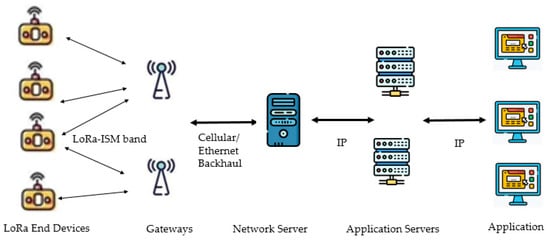
Figure 1.
Basic LoRa network architecture.
CSS modulation spreads the information signal spectrum by a continuously varying frequency chirp carrier signal. The extent of spreading that happens to the original data signal is termed the spreading factor (SF) [1]. One LoRa symbol can encode SF bits of information, and one symbol’s duration depends on SF and the bandwidth as given in,
where Ts is the symbol duration, SF is the spreading factor, and BW is the bandwidth. LoRa uses the forward error correction (FEC) method, and the code rate (CR) is {4/5, 4/6, 4/7, or 4/8}. Typically, bandwidth supported is {125, 250, 500} kHz and SF = {7, 8, 9, 10, 11, 12}. Transmit power values usually chosen are {2, 5, 8, 11, 14} dBm [7]. The channel frequency selected depends on the region of operation. Bandwidth, spreading factor, code rate, channel frequency, and transmit power are important parameters that can be chosen for LoRa modulation and influence the modulation bit rate and resistance to interference [8,9]. The communication range for higher SF values increases, but time on air (ToA) also increases, reducing the data rate. The symbol duration affects the time on air; as time on air increases, the energy required to transmit the data packet also increases. Thus, the SF value, the channel frequency, and transmit power decide the range and energy requirement. LoRa nodes communicate using pure ALOHA, and the LoRa network uses adaptive data rate (ADR) at the gateway, ensuring good network throughput. Different spreading factors result in orthogonal signals and data rate changes. The gateway can simultaneously receive several data rates on the same channel [10].
TVWS refers to broadcast frequency bands in certain parts of the spectrum that are unused due to the digitization of TV services and bands free at different times, as presented in Figure 2. The lower frequency ranges of TVWS (50–698 MHz) penetrate well through obstacles making them less prone to fading and multipath, thus enabling indoor and consumer applications. The bandwidth offered by TVWS is large, thus supporting various high-bit-rate applications too. In contrast to ISM bands, enough TVWS may be generally accessible, especially in rural regions, since there are fewer TV stations than in metropolitan areas [11]. TVWS has good propagation characteristics, excellent indoor penetration, and higher spectral efficiency, making it a good prospect for a wide range of significant indoor and outdoor wireless applications. TVWS is appropriate for applications that need a wide transmission range.
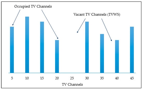
Figure 2.
TV white spaces illustration.
The Federal Communications Commission (FCC) permitted the unlicensed use of TVWS in 2008 [12]. Most countries have rules for the licensed or unlicensed use of TVWS. The United States, United Kingdom, Canada, Singapore, Mozambique, Japan, and Hong Kong have regulations for the use of TVWS for fixed and mobile wireless communications. The United States has enabled licensed access to TVWS for wireless broadband and mobile data services. The Indian government has issued experimental licenses in the 470–590 MHz band to perform trials at several places using TVWS, unlocking prospects for using the TVWS spectrum in India in either an unlicensed or lightly licensed manner. Literature studies show several TVWS use cases dedicated to rural wireless broadband access, home networks, WLAN applications, and smart metering. Several pilot projects, mostly in rural areas using TVWS, are demonstrated in Africa, Europe, Asia, North America, and Germany. The analog-to-digital TV transition has freed up the TVWS for future 5G networks in Portugal [11].
Different software platforms and hardware operating over various frequency ranges for LPWAN is available. LoRa transceivers operating in the 137 MHz to 1020 MHz frequency band are also currently available. Semtech, a leading member of the LoRa Alliance, has the SX126* and SX127* series of LoRa modules that support different frequency bands [13]. Most of the research and applications are focused on using LoRa in the ISM band, hence this attempt to study the use of TVWS frequencies, primarily the licensed bands for LoRa, as shown in Figure 3.
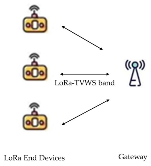
Figure 3.
TVWS-based LoRa model.
3. LoRa Radio Propagation Model
This study focuses on finding the data rate and the maximum range of TVWS-based LoRa. To estimate this, the receiver sensitivity for which the signal can be correctly detected or the maximum link budget needs to be computed. An SX1276/77/78/79—137 MHz to 1020 MHz low power long range transceiver is considered for the analysis in this study. The SF can vary from 6 to 12, and there are different values of bandwidth available for LoRa at TVWS frequencies. We have considered 62.5, 125,250, and 500 kHz. A specific SF and BW combination results in a particular data rate and receiver sensitivity [14], as shown in Table 1.

Table 1.
SX1276/77/78/79 module data rate (kbps) and receiver sensitivity (dBm) for different SF and BW.
The data rate in kbps is given as
where SF is the spreading factor, CR is the coding rate, and BW is the bandwidth.
The overall link budget [15] is given as in (3) for any wireless signal transmitted to the receiver by a transmitter.
where Pr and Pt denote the received and transmitted power in dBm, respectively, Gt and Gr are the transmitting and receiving antenna gains in dBi, respectively, Lt and Lr are the cable losses at the transmitter and receiver in dB, respectively—and Lp is the path loss.
Path loss Lp is the loss that occurs when a wireless signal travels over a distance d from the transmitter to the receiver, varies with the environment, and is modeled accordingly, as discussed further. Three scenarios, free space, outdoor-urban and rural, and indoor, are considered for estimating the range of LoRa transmissions in the 470–580 MHz TVWS frequency range. The parameters used for path-loss modeling are set to typical values [16] mentioned in Table 2. The main objective is to maximize the distance and still obtain the LoRa signal successfully at the receiver. The receiver sensitivity Pr for the specific combination of SF and BW is considered as per Table 1, and path loss is evaluated from (3). The maximum distance for this path loss can then be computed using the path-loss model as per the scenario.
Table 2.
Path-loss model parameters.
3.1. Propagation Models
In the context of signal propagation, three major scenarios can be considered free space, outdoors, and indoors. A free-space scenario can be described as a line-of-sight transmission from the transmitter to the receiver over a certain distance, and the path loss can be modeled using the commonly used free space path-loss model [17,18]. The free space path loss —is given as
where f is the frequency of transmission in MHz, dFSPL—is the distance between the transmitter and receiver in km. The maximum distance can be obtained from the maximum path loss as given in (5),
The widely accepted Okumura–Hata model is considered to study the range for LoRa transmissions using TVWS frequencies in outdoor urban environments [17]. It is an empirical model for rural, suburban, and urban settings, typically in the 150–1500 MHz frequency range, considering losses due to diffraction, reflection, and scattering without any prominent objects within the transmitter and receiver [19].
For urban settings
For small and medium cities
For big cities
where Lu is the path loss in urban regions (dB), f is the transmission frequency (MHz), hB is the base station antenna height (m), hM is the mobile station antenna height (m), CH is a factor for antenna height correction, du is the distance between the transmitter and receiver in kilometers.
For rural settings
where Lo is the path loss in open regions (dB), Lu is the average path loss from a small city form of the model (dB), and f is the transmission frequency in MHz.
Signal propagation and coverage in indoor systems depend on the building geometry, reflection from and diffraction around objects in the rooms, movement of people inside the room, and transmission loss through walls and other obstacles [20]. The indoor dominant path-loss model has been used to study signal propagation at frequencies such as 2.4 GHz [16] and TV signal frequencies [21]. The indoor dominant path-loss model considers the main path between the transmitter and the receiver and includes path loss, loss due to walls, and interaction loss due to changes in the direction of the propagating signal. The indoor path loss is given as.
where Lp(d0) represents the path loss at a distance d0, and n is the path-loss exponent. The wall loss is the sum of losses Lwx caused by each wall along the main path. The interaction loss is the sum of losses Liy caused by the change in the direction of the transmitting signal. Setting some typical parameter values for simplicity, the indoor path loss can be calculated as
where Lp(d0) is taken as 40 dB at a distance d0 = 1 m, path loss exponent n = 5 for indoor obstructed paths, and wall loss and interaction loss are taken as 6 and 3 dB, respectively, assuming an indoor office scenario [22,23]. The communication range can be computed from (11) as given in
3.2. Proposed LoRa over TVWS—Path-Loss Model (LoRaT-PLM)
Several path-loss models are studied in the literature for LoRa and TV transmissions distinctly. The authors in [24] have investigated the coverage and performance of LoRa for smart lighting and smart building application using the one slope path-loss model for a real urban scenario. An automated approach to estimate LoRa coverage focusing on the Okumura–Hata model is proposed using the available multispectral images from remote sensing [25]. A channel-attenuation model based on LoRa measurements is proposed to derive the expected path loss and estimate the coverage [26]. Most of these models have been used in the context of 868 MHz LoRa transmissions. A path-loss model for LoRa signals in the framework of TVWS needs to be explored.
Okumura–Hata model is a path-loss model commonly used to assess TV transmissions. When a transmitter sends any signal to a receiver, the signal strength changes due to obstructions such as mountains, construction structures, vegetation, and so on, and is termed as a shadowing effect. The shadowing effect, which is more prominent in outdoor signal propagation, impacts signal transmissions in terrestrial and wireless networks and needs to be addressed. In this paper, to consider and address this shadowing effect, especially for terrestrial TVWS-based LoRa transmissions, a hybrid path-loss model, based on the Okumura–Hata model, for TVWS-based LoRa is proposed with the inclusion of a correction factor Cs as given.
For urban settings
For rural settings
This newly designed is a correction factor that accounts for shadow fading. As shadow fading occurs when the line of sight is obstructed, it reflects conditions that may differ with corners and buildings that are more common for urban than rural scenarios. Hence for urban would be higher than that for rural environments, and it is considered as 7.2 dB and 6.4 dB for urban and rural scenarios, respectively [19]. Having computed the path loss Lu or Lo from (3), the maximum range can be calculated for urban and rural scenarios from (6) and (9) as per the Okumura–Hata model and from (13) and (14) as per the proposed LoRaT-PLM model.
4. Communication Range and Data Rate for TVWS-Based LoRa
Firstly, to investigate TVWS-based LoRa, the data rate and range estimation for different scenarios, SFs and BWs, and path-loss models is analyzed. Additionally, the comparative analysis of uplink delivery rate is carried out.
4.1. Range and Data Rate Analysis
As an SX1276/77/78/79—137 MHz to 1020 MHz low power long range transceiver is considered for this study, the receiver sensitivity and the data rate for this transceiver for a particular combination of SF and BW is known. From this information, the path loss can be evaluated using the link budget in (3). An appropriate path-loss model can then be utilized to estimate the maximum communication range. For the three scenarios studied, free space, outdoor–urban and rural, and indoor, Figure 4, Figure 5, Figure 6, Figure 7 and Figure 8 depict the data rate and maximum communication range for every combination of SF and BW, respectively.
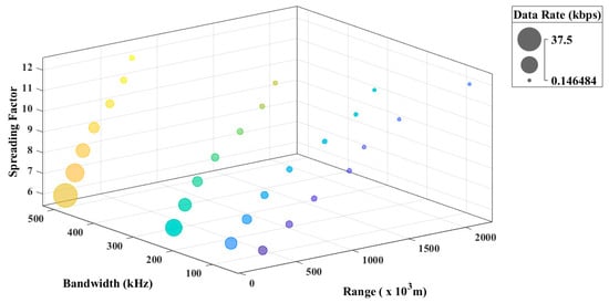
Figure 4.
Data rate and range characteristics for different SF and BW for the free space path-loss model.
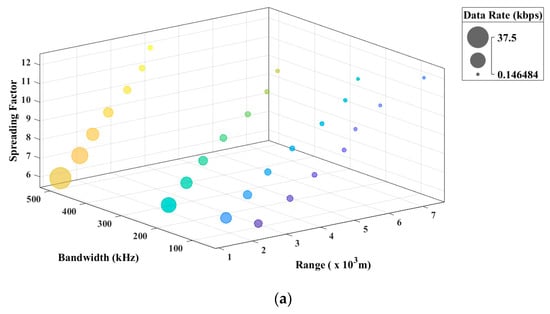

Figure 5.
(a). Data rate and range characteristics for different SF and BW for outdoor urban—big cities scenario with the Okumura–Hata model. (b). Data rate and range characteristics for different SF and BW for outdoor urban—big cities scenario with LoRaT-PLM model.
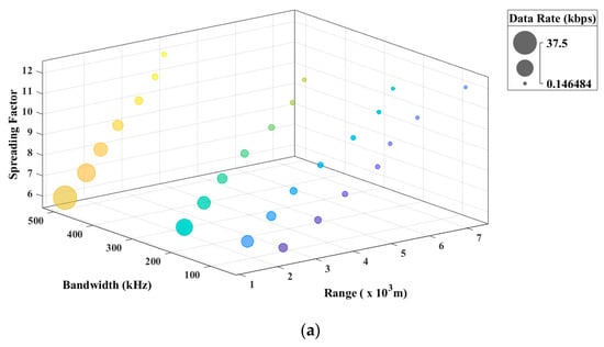
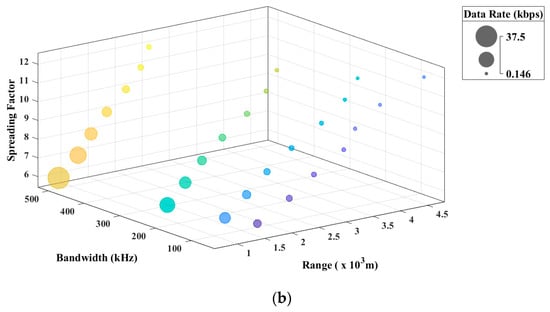
Figure 6.
(a). Data rate and range characteristics for different SF and BW for urban outdoor—small, medium cities scenario with the Okumura–Hata model. (b). Data rate and range characteristics for different SF and BW for urban outdoor—small, medium cities scenario with LoRaT-PLM model.
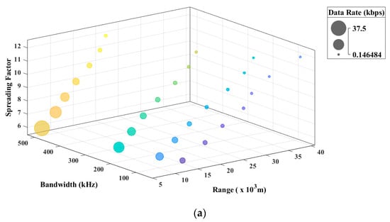
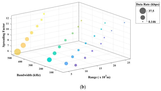
Figure 7.
(a). Data rate and range characteristics for different SF and BW for the rural outdoor scenario with the Okumura–Hata model. (b). Data rate and range characteristics for different SF and BW for the rural outdoor scenario with LoRaT-PLM model.
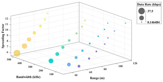
Figure 8.
Data rate and range characteristics for different SF and BW for the indoor scenario.
To understand the variation better, bubble graphs are drawn between four parameters: data rate, communication range, SF, and BW. The size of the bubbles in the graph indicates the data rate, with the bigger size indicating a higher data rate. The four colors of the bubbles depict the four different BW values, and the seven bubbles indicate the seven different SF values. The colour gradient for the seven different bubbles of the same bandwidth depicts the variation in SF values. As the range increases, the size of the bubble decreases, representing a reduction in the possible data rate. It is perceived that the data rate decreases with the increase in the communication range for all scenarios. Although the trend in all the graphs looks similar, the major point of difference is the communication range plotted on the x-axis for the different scenarios.
A. Free Space Scenario
Although the free space path-loss model evaluation according to (4) and (5) shows that the TVWS-based LoRa signal can achieve an extreme range of 2137.9 km in free space for SF = 12 and BW = 62.5 kHz with a data rate of 0.18 kbps as seen in Figure 4, it is a theoretical value that cannot be achieved practically. The maximum data rate of 46.8 kbps is obtained for BW = 500 kHz and SF = 6 with a range of 85.1 km.
B. Outdoor Scenario
Evaluation is carried out for the outdoor urban-big cities, small and medium cities, and rural scenarios using the Okumura–Hata and the proposed LoRaT-PLM models.
a. Outdoor Urban—Big Cities Scenario
Figure 5a represents the data rate and communication range characteristics for different SF and BW for outdoor urban–big cities scenarios evaluated according to (6) and (8). It is observed that the TVWS-based LoRa signal can achieve a maximum range of 7.25 km in urban outdoor—big cities scenario for SF = 12 and BW = 62.5 kHz with a data rate of 0.18 kbps, as seen in Figure 5a. The maximum data rate of 46.8 kbps is obtained for BW = 500 kHz and SF = 6 with a range of 1.2 km. Thus, the communication range for the outdoor–big cities scenario evaluated for urban environments varies from 1.2 km to 7.25 km, with data rates varying from 46.8 to 0.18 kbps, as depicted in Figure 5a.
Figure 5b represents the data rate and communication range characteristics for different SF and BW for outdoor urban–big cities scenarios using the LoRaT-PLM model calculated according to (8) and (13). It is observed that the TVWS-based LoRa signal can achieve a maximum range of 4.5 km in urban outdoor—big cities scenario for SF = 12 and BW = 62.5 kHz with a data rate of 0.18 kbps, as seen in Figure 5b. The maximum data rate of 46.8 kbps is obtained for BW = 500 kHz and SF = 6 with a range of 0.75 km. Thus, the communication range for outdoor—big cities scenario evaluated for urban environments varies from 0.75 km to 4.5 km, with data rates varying from 46.8 to 0.18 kbps, as depicted in Figure 5b.
b. Outdoor Urban—Small, Medium Cities Scenario
Figure 6a represents the data rate and communication range characteristics for different SF and BW for urban outdoor—small and medium cities scenarios computed using (6) and (7). It is observed that the TVWS-based LoRa signal can achieve a maximum range of 7.34 km in urban outdoor—small, medium cities scenario for SF = 12 and BW = 62.5 kHz with a data rate of 0.18 kbps as seen in Figure 6a. The maximum data rate of 46.8 kbps is obtained for BW = 500 kHz and SF = 6 with a range of 1.21 km.
Figure 6b represents the data rate and communication range characteristics for different SF and BW for urban outdoor—small and medium cities scenarios using the LoRaT-PLM model estimated as in (7) and (13). It is observed that the TVWS-based LoRa signal can achieve a maximum range of 4.6 km in urban outdoor—small, medium cities scenario for SF = 12 and BW = 62.5 kHz with a data rate of 0.18 kbps as seen in Figure 6b. The maximum data rate of 46.8 kbps is obtained for BW = 500 kHz and SF = 6 with a range of 0.76 km.
c. Outdoor—Rural Scenario
Figure 7a represents the data rate and communication range characteristics for different SF and BW for rural outdoor scenarios analyzed as in (6) and (9). It is observed that the TVWS-based LoRa signal can achieve a maximum range of 39.2 km in urban outdoor—big cities scenario for SF = 12 and BW = 62.5 kHz with a data rate of 0.18 kbps, as seen in Figure 7a. The maximum data rate of 46.8 kbps is obtained for BW = 500 kHz and SF = 6 with a range of 6.49 km.
Figure 7b represents the data rate and communication range characteristics for different SF and BW for rural outdoor scenarios calculated as in (7) and (14). It is observed that the TVWS-based LoRa signal can achieve a maximum range of 26 km in urban outdoor—big cities scenario for SF = 12 and BW = 62.5 kHz with a data rate of 0.18 kbps, as seen in Figure 7b. The maximum data rate of 46.8 kbps is obtained for BW = 500 kHz and SF = 6 with a range of 4.3 km.
C. Indoor Scenario
Figure 8 represents the data rate and communication range characteristics for different SF and BW for indoor scenarios computed according to (11) and (12). It is observed that the TVWS-based LoRa signal can achieve a maximum communication range of 117.8 m indoors for SF = 12 and BW = 62.5 kHz with a data rate of 0.18 kbps, as seen in Figure 8. The maximum data rate of 46.8 kbps is obtained for BW = 500 kHz and SF = 6 with a range of 32.35 m.
The proposed LoRaT-PLM model for outdoor urban and rural scenarios exhibits higher path loss for all the different ranges compared to the Okumura–Hata model as it considers the impact of the shadowing effect. This higher path-loss estimate can lead to a better margin allocation in the link budget, taking care of all the possible losses. The link budget can then be a tool to estimate the transmit power requirement more effectively. This can lead to better interference avoidance, more successful transmissions, and hence better energy efficiency.
4.2. Uplink Delivery Rate
To further examine the proposed LoRaT-PLM model, evaluation based on uplink delivery rate (UDR), defined as the percentage of packets correctly received by the gateway, is carried out. LoRaWANSim, a LoRaWAN simulator [27], is used to simulate LoRa transmissions for an outdoor urban scenario with one gateway. The uplink delivery rate is computed by varying the distance between the end device and the gateway and considering three path-loss models: the proposed LoRaT-PLM, Okumura–Hata (OH), and the path-loss model proposed for LoRa in [19]. LoRaT-PLM and OH path-loss models are used in LoRa transmissions using the 470 MHz TVWS frequency, whereas the model in [19] uses 868 MHz ISM band frequency for LoRa.
Figure 9 depicts the UDR as a function of the logarithmic distance between the end device and the gateway. It is seen that UDR decreases as the distance between the end device and the gateway increases, which is as expected. In addition, the proposed LoRaT-PLM model gives better UDR than the conventional OH and the model proposed in [19]. Thus, although the path loss predicted by the LoRaT-PLM model is comparatively more, the model benefits from better UDR, as seen in Figure 9.
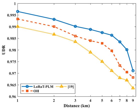
Figure 9.
Comparison of the proposed LoRaT-PLM model with OH and model presented in [19] outdoor urban scenario—UDR as a function of distance.
5. Discussions
This work studies LoRa transmissions using the TVWS bands, and the maximum communication range with different bandwidth and spreading factor values is evaluated. The study covers three different scenarios: free space, outdoor: urban and rural, and indoor. Maximum range can be obtained by increasing the spreading factor and decreasing the bandwidth. As the data rate increases, the range reduces. The range of LoRa using TVWS bands is estimated based on the link budget calculations and the specifications mentioned in the datasheet for the LoRa hardware.
The free space path-loss scenario gives a maximum theoretical range of 2137.9 km at the largest SF value and lowest bandwidth. However, it is not practically feasible due to the presence of obstacles and other interfering signals. These results can be useful for comparing the performance of LoRa at other frequencies. The maximum range with LoRa at TVWS frequencies using the free space path-loss model is 2137.9 km, more than double the range of 921 km at 868 MHz (ISM band) and almost 16 times that of 133 km at 2.4 GHz. The indoor range also varies from 32.35 to 117.8 m, much more than LoRa at 868 MHz bands or about 1.5 times that at 2.4 GHz band. These indoor calculations can vary with lower path-loss exponent values giving an even better range.
For the outdoor scenario, the maximum communication range is about 7 km for urban and 32 km for rural settings with the Okumura–Hata model. In contrast, it is 4.6 km and 26 km, respectively, with the LoRaT-PLM model. This is better than 5 km for urban and 15 km for rural using 868 MHz and a maximum of 443 m for 2.4 GHz bands. The maximum data rate of 46.8 kbps for LoRa at TVWS frequencies is less than 250 kbps for LoRa at 2.4 GHz and almost similar to LoRa at 868 MHz with 40 kbps. Data-rate calculations also depend on the available bandwidth at different frequencies, the LoRa hardware used, and the distance between the transmitter and receiver [16,28].
From these studies, it can be inferred that TVWS-based LoRa can be suitable for long-range applications in the outdoor scenario and for indoor applications with better coverage. Techniques for managing interference are also essential in such applications. Since it uses licensed bands, this approach can be useful to avoid the interference issues common in the ISM band. In addition, since the coverage is better, fewer gateways would be required reducing the hardware requirement. Technical challenges include the larger antenna size at the lower TVWS frequency bands, and much research is focused on reducing the antenna dimensions. A small printed inverted -F antenna (PIFA) embedded on the LoRa sensor node circuit board is designed for IoT applications and gives adequate gain over the 410–441 MHz LoRa frequency band [29]. A microstrip antenna, fabricated for being used with TVWS technology in the range of 477 to 1100 MHz, has also been designed that gives a sufficient gain in the desired band. This antenna is much smaller than a typical log periodic antenna and can provide moderate bandwidth [30]. LoRa operates in the unlicensed radio spectrum and the frequencies and number of channels allotted are often country-specific. This also poses challenges for the implementation of backend systems. The TVWS band presents a path-loss advantage over the unlicensed ISM bands (868 MHz and 2.4 GHz) due to the operating frequency. The recommended frequency ranges for TVWS regulations in different countries also vary, but the bandwidth and the number of channels available is greater. Various regions have the 433 MHz band, which is the ISM band designated for LoRa transmissions. Most of the allocations in this band support up to 125 MHz bandwidth [7]. As mentioned, TVWS bands are licensed and underutilized; the supported bandwidth can be extended to 250 KHz and 500 KHz, thus enhancing the data-rate capabilities. TVWS offers a large band that can accommodate more channels and this can also be one approach to tackle interference. In addition, LoRa hardware that supports these frequencies is available. Thus, with these developments, TVWS will emerge as a viable option for LoRa-based applications.
6. Conclusions
As LoRa hardware operating at different transmission frequency ranges is available, LoRa technology can also use TVWS frequency bands other than their conventional ISM bands. This enables LPWAN applications in the licensed TVWS bands, avoiding interference and coexistence issues in the high-density ISM band. In this study, we propose a path-loss model for TVWS-based LoRa transmissions and evaluate the communication range and data rate for different scenarios such as free space, outdoor (both urban and rural), and indoor. The range achieved with LoRa increases as the transmissions shift to the lower TVWS frequency ranges compared to the ISM band as per the configuration of SF and BW. The proposed path-loss model also fares better in terms of uplink delivery rate when compared with the conventional model and other models proposed in the literature. This study can thus provide an estimate to the users about the expected data rate, coverage, and applicable areas for LoRa deployments. Characterizing the radio channel using the proposed path-loss model would be beneficial for designing TVWS-based LoRa networks. Other parameters, such as signal-to-noise ratio, received signal strength indication, and packet delivery rate, can also be investigated for further analysis. Although the approach offers several advantages, a rigorous evaluation of the hardware requirement, the transition and adoption challenges and the cost effectiveness of the same against the backdrop of application diversity is essential. Experimental evaluation of all these parameters can additionally be carried out to support the findings. This approach can further explore precise indoor and outdoor applications with longer-range requirements, such as remote monitoring, asset tracking, and others. The outputs of this study can be useful for effectively utilizing white spaces and the future development of TVWS-based LoRa LPWANs.
Author Contributions
All the authors have contributed equally towards the conceptualization, methodology, analysis, investigation, and resources. The original draft and changes were also performed by all the authors. All authors have read and agreed to the published version of the manuscript.
Funding
This research was supported by Princess Nourah bint Abdulrahman University Researchers Supporting Project Number (PNURSP2023R97), Princess Nourah bint Abdulrahman University, Riyadh, Saudi Arabia.
Data Availability Statement
Not applicable.
Acknowledgments
Princess Nourah bint Abdulrahman University Researchers Supporting Project Number (PNURSP2023R97), Princess Nourah bint Abdulrahman University, Riyadh, Saudi Arabia. In addition, the authors would like to acknowledge Dr. Vishwanath Karad MIT World Peace University, Pune, India and Deanship of Scientific Research, Taif University, Taif, Saudi Arabia, for funding this work.
Conflicts of Interest
The authors declare no conflict of interest.
References
- LoRa® and LoRaWAN®: A Technical Overview. December 2019. Available online: https://lora-developers.semtech.com/uploads/documents/files/LoRa_and_LoRaWAN-A_Tech_Overview-Downloadable.pdf (accessed on 15 June 2023).
- Applications and Future of LoRa WAN Technology. 31 July 2022. Available online: https://www.rfpage.com/applications-future-lora-wan-technology/ (accessed on 14 June 2023).
- LoRa Applications. Available online: https://www.semtech.com/lora/lora-applications (accessed on 14 June 2023).
- Azmi, N.; Kamarudin, L.; Mahmuddin, M.; Zakaria, A.; Shakaff, A.; Khatun, S.; Kamarudin, K.; Morshed, M. Interference issues and mitigation method in WSN 2.4 GHz ISM band: A survey. In Proceedings of the 2014 2nd International Conference on Electronic Design (ICED), Penang, Malaysia, 19–21 August 2014; p. 403. [Google Scholar] [CrossRef]
- Lousado, J.P.; Antunes, S. Monitoring and Support for Elderly People Using LoRa Communication Technologies: IoT Concepts and Applications. Future Internet 2020, 12, 206. [Google Scholar] [CrossRef]
- Saeed, R.A.; Mokhtar, R.A.; Chebil, J.; Abdallah, A.H. TVBDs Coexistence by Leverage Sensing and Geo-location Database. In Proceedings of the 2012 International Conference on Computer and Communication Engineering (ICCCE), Kuala Lumpur, Malaysia, 3–5 July 2012; pp. 33–39. [Google Scholar]
- LoRaWAN® Regional Parameters 46 RP002-1.0.4. 2021. Available online: https://lora-alliance.org/wp-content/uploads/2021/05/RP002-1.0.3-FINAL-1.pdf (accessed on 15 June 2023).
- Jorke, P.; Bocker, S.; Liedmann, F.; Wietfeld, C. Urban channel models for smart city IoT-networks based on empirical measurements of LoRa-links at 433 and 868 MHz. In Proceedings of the 2017 IEEE 28th Annual International Symposium on Personal, Indoor, and Mobile Radio Communications (PIMRC), Montreal, QC, Canada, 8–13 October 2017. [Google Scholar] [CrossRef]
- Chaudhari, B.S.; Zennaro, M.; Borkar, S. LPWAN Technologies: Emerging Application Characteristics, Requirements, and Design Considerations. Future Internet 2020, 12, 46. [Google Scholar] [CrossRef]
- Petajajarvi, J.; Mikhaylov, K.; Roivainen, A.; Hanninen, T.; Pettissalo, M. On the coverage of LPWANs: Range evaluation and channel attenuation model for LoRa technology. In Proceedings of the 2015 14th International Conference on ITS Telecommunications (ITST), Copenhagen, Denmark, 2–4 December 2015; pp. 55–59. [Google Scholar] [CrossRef]
- Askhedkar, A.; Chaudhari, B.; Zennaro, M.; Pietrosemoli, E. TV white spaces for low-power wide-area networks. In LPWAN Technologies for IoT and M2M Applications; Chaudhari, B., Zennaro, M., Eds.; Elsevier: Amsterdam, The Netherlands; Academic Press: Cambridge, MA, USA, 2020; pp. 167–179. ISBN 9780128188804. [Google Scholar] [CrossRef]
- Zhang, W.; Yang, J.; Zhang, G.; Yang, L.; Yeo, C.K. TV white space and its applications in future wireless networks and communications: A survey. IET Commun. 2018, 12, 2521–2532. [Google Scholar] [CrossRef]
- LoRa Products Guide. Available online: https://www.semtech.com/uploads/design-support/SEMTECH_LORA_PG_web.pdf (accessed on 15 June 2023).
- Semtech SX1276/77/78/79 Wireless and Sensing Products Datasheet. Available online: https://www.semtech.com/products/wireless-rf/lora-connect/sx1276#documentation (accessed on 14 June 2023).
- Heereman, F.; Joseph, W.; Tanghe, E.; Plets, D.; Verloock, L.; Martens, L. Path loss model and prediction of range, power and throughput for 802.11n in large conference rooms. AEU Int. J. Electron. Commun. 2012, 66, 561–568. [Google Scholar] [CrossRef][Green Version]
- Janssen, T.; BniLam, N.; Aernouts, M.; Berkvens, R.; Weyn, M. LoRa 2.4 GHz Communication Link and Range. Sensors 2020, 20, 4366. [Google Scholar] [CrossRef] [PubMed]
- Theodore, S. Rappaport, Wireless Communications: Principles and Practice, 2nd ed.; Pearson Education: New York, NY, USA; Prentice Hall: Hoboken, NJ, USA, 2009. [Google Scholar]
- Germani, L.; Mecarelli, V.; Baruffa, G.; Rugini, L.; Frescura, F. An IoT Architecture for Continuous Livestock Monitoring Using LoRa LPWAN. Electronics 2019, 8, 1435. [Google Scholar] [CrossRef]
- El Chall, R.; Lahoud, S.; El Helou, M. LoRaWAN Network: Radio Propagation Models and Performance Evaluation in Various Environments in Lebanon. IEEE Internet Things J. 2019, 6, 2366–2378. [Google Scholar] [CrossRef]
- Recommendation ITU-R P.1238-8. Propagation Data and Prediction Methods for the Planning of Indoor Radio Communication Systems and Radio Local Area Networks in the Frequency Range 300 MHz to 100 GHz. Available online: https://www.itu.int/dms_pubrec/itu-r/rec/p/r-rec-p.1238-8-201507-s!!Pdf-e.pdf (accessed on 8 June 2023).
- Adonias, G.L.; Carvalho, J.N. Assessment of the Dominant Path Model and Field Measurements for NLOS DTV Signal Propagation. In Proceedings of the IEEE Radio and Antenna Days of the Indian Ocean (IEEE RADIO 2017), Cape Town, South Africa, 25–28 September 2017; Volume 321, p. 012004. [Google Scholar] [CrossRef]
- Plets, D.; Joseph, W.; Vanhecke, K.; Tanghe, E.; Martens, L. Simple Indoor Path Loss Prediction Algorithm and Validation in Living Lab Setting. Wirel. Pers. Commun. 2013, 68, 535–552. [Google Scholar] [CrossRef]
- Razali, N.A.M.; Habaebi, M.H.; Zulkurnain, N.F.; Islam, M.R.; Zyoud, A. The distribution of path loss exponent in 3D indoor environment. Int. J. Appl. Eng. Res. 2017, 12, 7154–7161. [Google Scholar]
- Pasolini, G.; Buratti, C.; Feltrin, L.; Zabini, F.; De Castro, C.; Verdone, R.; Andrisano, O. Smart City Pilot Projects Using LoRa and IEEE802.15.4 Technologies. Sensors 2018, 18, 1118. [Google Scholar] [CrossRef] [PubMed]
- Demetri, S.; Zúñiga, M.; Picco, G.P.; Kuipers, F.; Bruzzone, L.; Telkamp, T. Automated estimation of link quality for LoRa: A remote sensing approach. In Proceedings of the 18th ACM/IEEE International Conference on Information Processing in Sensor Networks (IPSN), Montreal, QC, Canada, 16–18 April 2019. [Google Scholar] [CrossRef]
- Seye, M.R.; Ngom, B.; Gueye, B.; Diallo, M. A Study of LoRa Coverage: Range Evaluation and Channel Attenuation Model. In Proceedings of the 1st International Conference on Smart Cities and Communities (SCCIC), Ouagadougou, Burkina Faso, 24–26 July 2018; pp. 1–4. [Google Scholar] [CrossRef]
- Marini, R.; Mikhaylov, K.; Pasolini, G.; Buratti, C. LoRaWANSim: A Flexible Simulator for LoRaWAN Networks. Sensors 2021, 21, 695. [Google Scholar] [CrossRef] [PubMed]
- Haxhibeqiri, J.; Karaagac, A.; Van den Abeele, F.; Joseph, W.; Moerman, I.; Hoebeke, J. LoRa Indoor Coverage and Performance in an Industrial Environment: Case Study. In Proceedings of the 22nd IEEE International Conference on Emerging Technologies and Factory Automation (ETFA), Limassol, Cyprus, 12–15 September 2017; pp. 1–8. [Google Scholar] [CrossRef]
- Zhang, Q.; Gao, Y. Embedded Antenna Design on LoRa Radio for IoT Applications. In Proceedings of the 12th European Conference on Antennas and Propagation (EuCAP 2018), London, UK, 9–13 April 2018; pp. 1–3. [Google Scholar] [CrossRef]
- Vithanawasam, C.K. Design and Analysis of TVWS Antenna for Rural Wireless Connectivity. Master’s Thesis, Swinburne University of Technology Sarawak Campus, Kuching, Malaysia, 2021. Available online: http://hdl.handle.net/1959.3/459709 (accessed on 23 June 2023).


Disclaimer/Publisher’s Note: The statements, opinions and data contained in all publications are solely those of the individual author(s) and contributor(s) and not of MDPI and/or the editor(s). MDPI and/or the editor(s) disclaim responsibility for any injury to people or property resulting from any ideas, methods, instructions or products referred to in the content. |
© 2023 by the authors. Licensee MDPI, Basel, Switzerland. This article is an open access article distributed under the terms and conditions of the Creative Commons Attribution (CC BY) license (https://creativecommons.org/licenses/by/4.0/).