


Abstract
Power converters are fundamental components in vehicle electrification systems. However, their inherently nonlinear and time-varying condition requires complex design procedures when conventional control strategies based on linear small-signal models are employed. This work proposes a simplified and hardware-oriented DC-DC converter control methodology that combines fuzzy logic and Neural Networks in a sequential manner. A fuzzy logic fuzzy controller is first used to generate a dataset of control actions under closed-loop operation. A lightweight neural network is then trained using the obtained data to approximate this mapping and subsequently replace the fuzzy controller in real-time operation. To validate the approach, a bidirectional buck–boost DC-DC converter is designed for applications in the powertrain of electric vehicles with 500 kHz switching frequency and 13 kW power rating. The control algorithm is embedded in an FPGA to demonstrate its suitability for hardware deployment. The experimental results show a reduction in RMSE of 33.7% and a decrease in the settling time of at least 51.7% when compared with a benchmark PID control.
1. Introduction
The combustion of fossil fuels produces adverse effects on human health and the environment. Ship-tracks along major maritime shipping routes [1], and increased exposure to toxic pollutants such as [2] and [3] are some examples. Mass loss from glaciers, marine heatwaves and loss of marine biodiversity are considered effects of human-made climate change [4,5]. The Sustainable Development Goals from the United Nations aim to solve real-world problems. Goals 7, 11 and 13 focus on Clean and Accessible Energy, Sustainable Cities, and Climate Action [6]. Until 2020, 95% of the energy employed in the transportation sector was derived from petroleum [7]. Electric vehicles (EVs) have been developed to solve this issue.
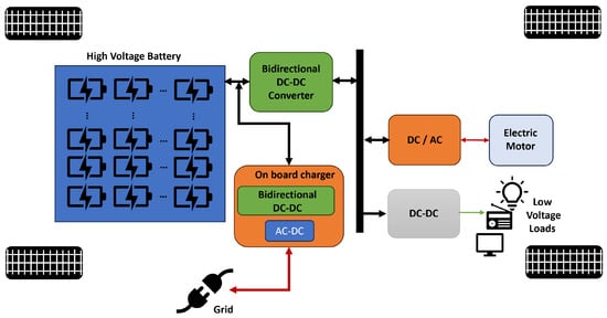
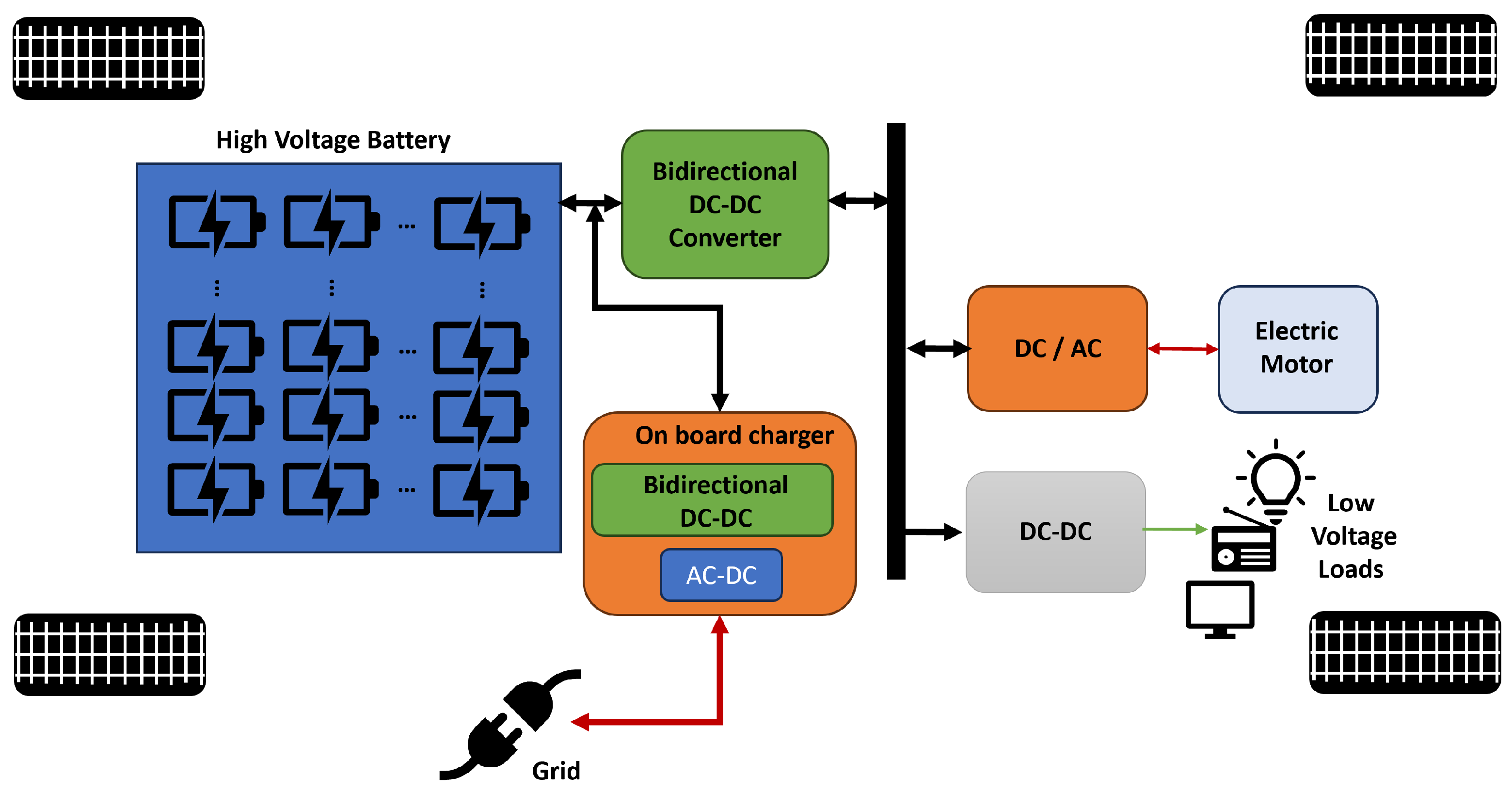
However, their higher cost and shorter driving range compared to fossil-fuel-powered vehicles remain significant barriers to widespread adoption. In this context, power converters play a crucial role in vehicle electrification systems as key interfaces between the energy sources and loads. Figure 1 shows a block diagram of the corresponding powertrain in an EV. Bidirectional DC-DC converters allow for power flow between the electric motor and the battery during traction and regenerative braking operation modes. Also, they add vehicle-to-grid (V2G) capabilities [8].
Figure 1.
Block diagram of electric vehicle power train.
For power converters, Wide Bandgap (WBG) devices have been considered an alternative to traditional Si power transistors since they offer higher switching frequency and power ratings [9]. The size of passive components can be reduced at higher frequencies, thus increasing the power density [10]. However, this also reduces the time available to compute the control action of the converter. Among the different approaches recently proposed to design control methods for power converters, two main trends can be identified: conventional control and artificial-intelligence-based control [11]. Within the first trend, the Proportional–Integral–Derivative (PID) controller remains the most widely used conventional control strategy in industrial applications due to its simplicity, robustness, and low hardware resource requirements. Well-defined stability analysis and tuning methods for PID control of Linear Time Invariant (LTI) systems have already been developed [12]. However, DC-DC converters are nonlinear time varying devices that require linearization around an operating point which is only valid in small signal regions [13,14].
Detailed mathematical models are typically required to implement high-performance control strategies such as Model Predictive Control (MPC) [15] or Sliding Mode Control (SMC) [16,17,18], which have demonstrated excellent results in a wide range of applications. However, these approaches often involve increased design complexity and rely on accurate system modeling, which may not always be readily available in practical scenarios. Elementary converter topologies have been thoroughly reviewed, and small-signal models are already available [19]. However, as circuit topologies increase in complexity, mathematical analysis becomes a task for control specialists, which limits their widespread adoption. The second trend in power converter control is based on artificial intelligence algorithms, where Neural Networks (NNs) and fuzzy logic (FL) are among the most popular approaches. Both methods can be designed without relying on complex mathematical models, and Neural Networks can provide real-time capability at high switching frequencies [9,20]. However, Neural Networks require large amounts of high quality training data. To address this, high-performance control methods (e.g., MPC [21,22,23]) are often used with the converter to generate the dataset. Yet, as mentioned earlier, MPC is computationally more complex and requires accurate system models.
Neural Networks have been designed by incorporating other control methods into their architecture as hidden layers or activation functions. Heuristic algorithms, such as Particle Swarm Optimization (PSO) or Bat Optimization (BO), are used to determine optimal controller parameters, which are then included as hyperparameters of the Neural Networks [13,14]. Dynamic Programming (DP) has also been implemented with this objective [24]. However, these adaptive approaches still require accurate models to define the cost or approximation functions [25,26]. The parameters of the converter to be controlled can be embedded into the networks using radial basis functions [27,28] or fuzzy logic [21,29]. Nevertheless, more sophisticated algorithms demand greater computational resources, thereby limiting real-time implementation.
PID is a widely used control method for bidirectional DC–DC converters in electric vehicle applications. Dual-input interleaved [30] and high-gain bidirectional DC-DC converters [31] have been designed for EV powertrains using PID control. To achieve faster response, a nonlinear control approach based on Input–Output Feedback Linearization (IOFL) has been proposed for a topology combining a cascade buck and quadratic boost [32]. However, these proposed topologies are typically designed for low power and low switching frequencies.
A summary of recent intelligent control methods for DC–DC converters is presented in Table 1, highlighting features such as application, switching frequency, topology, control mode, and transient performance. The column labeled “hardware” indicates the HIL device, microcontroller, or FPGA used for validation. Neural Networks are employed in the majority of the reported control methods. An ANFIS controller is presented in [33] for a bidirectional buck–boost converter operating at a switching frequency of 250 kHz; however, it is only validated through computer simulations. In [34], the parameters of a PI controller are determined using an Adaptive Tabu Search algorithm and validated through a processor-in-the-loop methodology at a switching frequency of 10 kHz.
Some of these approaches adopt data-driven control strategies, where an NN is trained to approximate a control law from generated datasets [32]. These datasets are typically obtained from model-based controllers such as MPC [9], SMC [14,16], or optimal control frameworks [18,22]. While these approaches have demonstrated high effectiveness, they generally require accurate system models and involve significant computational effort during data generation. In parallel, neuro-fuzzy and adaptive neuro-fuzzy methods [27,33] integrate fuzzy logic within neural architectures, achieving strong performance at the cost of increased structural and computational complexity. In this context, the proposed approach uses a fuzzy logic controller as a model-free expert to generate training data, enabling an NN to learn the control behavior in a simplified manner and allowing for a lightweight implementation suitable for efficient hardware deployment. Therefore, this approach represents a simple methodology for DC–DC converter control that is hardware-ready to operate at high switching frequencies and power levels required in electric vehicle applications, thus addressing the need to bridge the gap between academic research and industrial application [35,36].
Table 1.
Summary of intelligent control methods for power converters, (– not specified).
In this work, a novel approach is proposed to generate high-quality training data without the use of complex conventional control methods or resource-intensive optimization. Simplicity is desired to facilitate design in engineering applications [38]. The proposed method consists of combining fuzzy logic control to generate training data for a neural network. In this way, the strong capabilities of fuzzy logic and neural networks for nonlinear function representation are leveraged together, providing a simple method for nonlinear system control. Additionally, the knowledge of experienced engineers can be incorporated into the control design, facilitating its development and, consequently, its wider adoption. To validate the proposed control method, a bidirectional DC–DC converter was designed for electric vehicle applications and evaluated using Hardware-in-the-Loop (HIL) methodologies. HIL enables a faster transition from control algorithm conception to deployment on real-time hardware platforms such as microcontrollers or FPGAs [39]. The rest of this paper is organized as follows: Section 2 describes the design of the bidirectional DC–DC converter topology, with PID control presented as a benchmark for comparison purposes. Section 3 details the data generation process based on the design of a fuzzy logic controller. Section 4 presents the architecture and training procedure of the neural network. Section 5 reports the experimental validation using FPGA-in-the-Loop (FIL), along with the results and discussion. Finally, Section 6 presents the concluding remarks.
2. Bidirectional DC-DC Converter
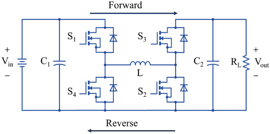
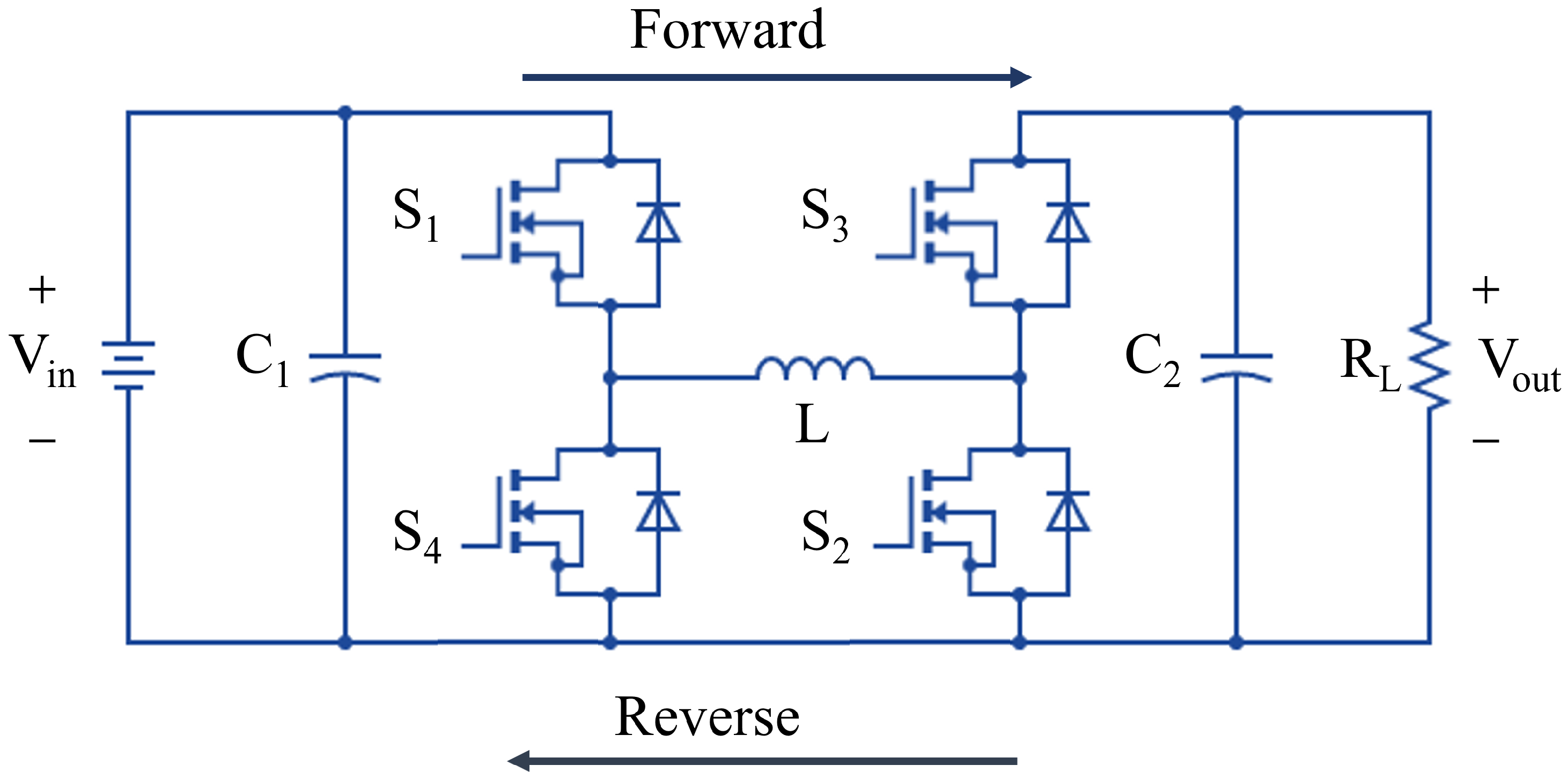
A bidirectional DC–DC converter topology for EV applications is shown in Figure 2. This topology provides buck and boost capabilities in both directions and can be interleaved to reduce the current in the power switches [40,41]. The operating modes are determined by the power switch states, as shown in Table 2.
Figure 2.
Bidirectional DC-DC converter with buck and boost modes.
Table 2.
Operating modes of the bidirectional converter from Figure 2, (S—switching, 0—switch off, 1—switch on).
2.1. Buck Mode
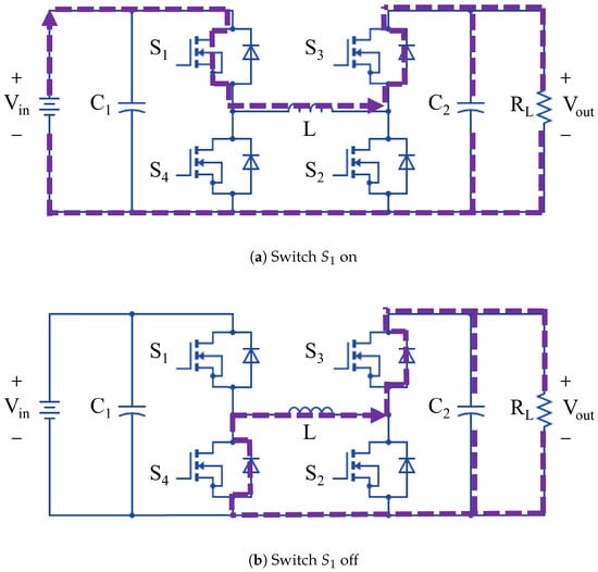
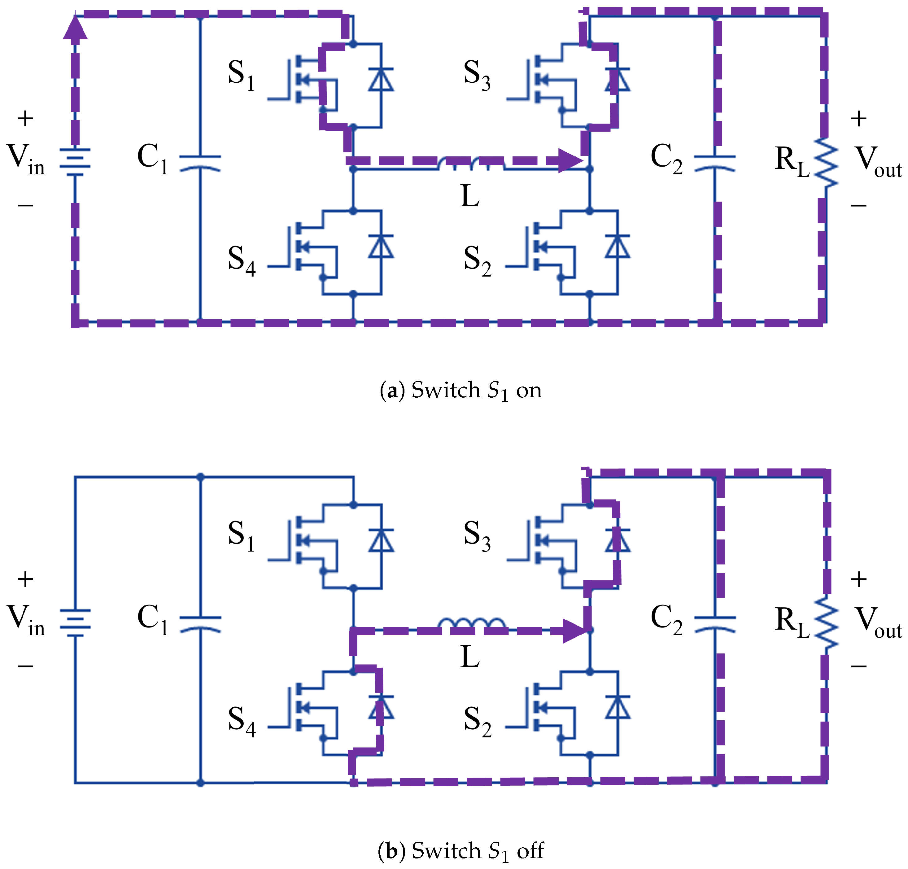
As shown in Table 2, buck operation in the forward direction requires S1 to switch while all other switches remain off, resulting in the circuit topologies illustrated in Figure 3a,b. The reverse direction is symmetric; therefore, its analysis is omitted. Under continuous conduction mode (CCM), the minimum required values of the inductor L and capacitor are given by [42]:
where represents the load resistance, is the switching frequency, and denote the minimum and maximum duty cycles, respectively, and is the equivalent series resistance (ESR) of the output filter capacitor .
Figure 3.
Operation of the converter in forward buck mode (a) during D, switch is ON transfering the input power to the load and (b) during (1-D), is off, and power flows through the reverse diode in .
2.2. Boost Mode
In this operating mode, with turned on and and turned off, the converter reduces to the fundamental boost topology. Under continuous conduction mode (CCM), the minimum required values of the inductor L and the output filter capacitor are given by [42]:
where denotes the maximum peak-to-peak voltage ripple across the output filter capacitor . The minimum component values that satisfy the design specifications in both buck and boost operating modes were selected. Table 3 summarizes the parameters of the chosen bidirectional DC–DC converter. A rated power of 13 kW was selected to operate the system within the SAE J1772 charging categories for AC Level 2 and DC Level 1 electric vehicle charging [43]. From Equations (1)–(4), it can be observed that the values of the passive components are inversely proportional to the switching frequency. Therefore, increasing the switching frequency reduces the size of the required inductors and capacitors and, consequently, the overall size of the converter. The advancement of traditional power switches made from Si has reached physical constraints that limit further increases in switching frequency. However, new devices made from Gallium Nitride (GaN) and Silicon Carbide (SiC) exhibit enhanced performance, enabling high-frequency operation with reduced switching losses. Although GaN devices can switch at higher frequencies than SiC devices, the latter can operate at higher power levels. Consequently, a switching frequency of 500 kHz was selected for this work to take advantage of the superior capabilities offered by SiC Wide Bandgap (WBG) devices, which cannot be achieved with traditional Si power switches [10,44].
Table 3.
Bidirectional DC-DC converter parameters.
Passive components were selected using standard continuous conduction mode (CCM) design equations under worst-case conditions (maximum duty cycle, load resistance, and switching frequency). The final values in Table 3 ensure acceptable current and voltage values in both buck and boost modes at 500 kHz operation [45].
2.3. PID Control
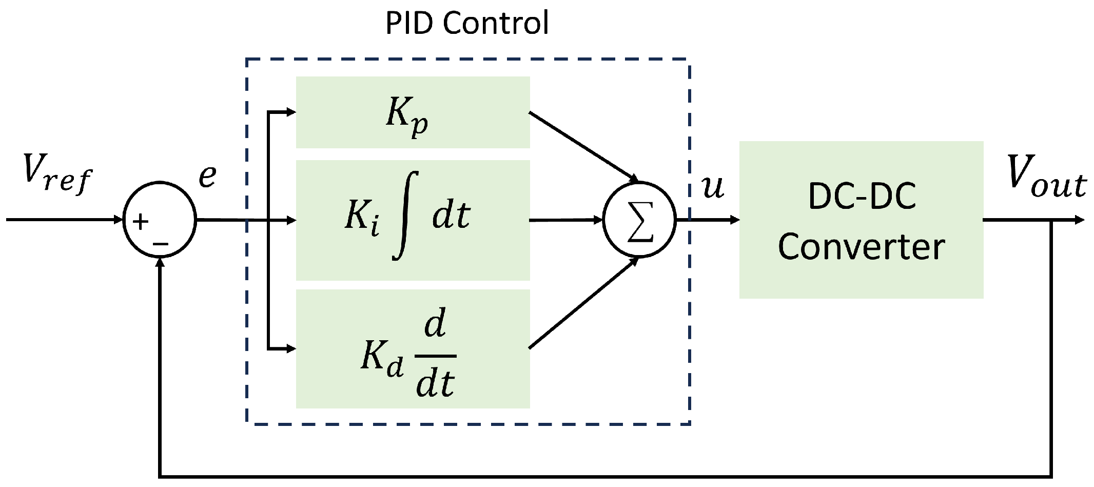
The bidirectional DC-DC converter exhibits time-varying behavior due to Pulse Width Modulation (PWM) condition, which is of nonlinear nature [19,42]. Therefore, the converter can be described as a nonlinear, time-varying system. Traditional circuit control analysis methods are primarily developed for Linear Time-Invariant (LTI) systems and typically involve averaging, linearization, and transformation into the s-domain. The block diagram of the PID controller operating in voltage control mode is shown in Figure 4, where represents the voltage error and u denotes the control action. For both buck and boost converters, the control to output transfer functions are given by [19]:
Figure 4.
Block diagram of PID control in a closed loop with the DC-DC bidirectional converter.
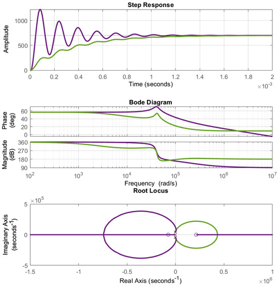
The control-to-output transfer functions, using the values from Table 3, were used to define the values of and for the PID controller [45]. Figure 5 shows the results of traditional control analysis: step response, frequency response, and root locus. The purple lines in the three graphs correspond to the open-loop response of the converter, while the green lines represent the response after PID control. The open-loop behavior exhibits an unstable system, characterized by high voltage overshoot in the step response, non-minimum phase behavior in the frequency response, and a zero in the right-half plane (RHP) of the complex plane. In contrast, the PID closed-loop response eliminates the voltage overshoot and yields a minimum-phase frequency response. However, multiple linearizations are required if the converter operates at different operating points. Additionally, the presence of a zero in the right-half plane (RHP) of the boost converter transfer function leads to instability, further complicating the control design [42,46]. This section highlights the stability issues associated with converter control using conventional linear techniques, as well as the limitations of PID control, particularly in boost mode, where right-half-plane zeros introduce non-minimum phase behavior. In contrast, the proposed neuro-fuzzy approach does not rely on linearization and is inherently suitable for nonlinear operation. Stable performance is verified through simulations across the full operating range (200–800 V), all modes of operation (buck/boost, forward/reverse), and FIL validation.
Figure 5.
PID control design for DC-DC bidirectional converter in boost mode [45]. The system presents (top) the oscillatory behaviour (middle) non-minimum phase and (bottom) a zero in the right-hand of the complex plane. Purple lines correspond to open-loop response of the converter; green lines represent the response after PID control.
3. Fuzzy Logic Control
The Mamdani fuzzy logic control approach has a heuristic nature, embedding human cognitive processes into control in a simple way. Fuzzy logic control operates without accurate mathematical models and can handle nonlinear systems, often showing better performance than conventional nonlinear controllers. The nonlinear dynamics of the converter are transformed into human-like linguistic terms. Then, based on practical experience and system understanding, a nonlinear control law can be designed [47,48]. The current state of research on fuzzy inference systems includes highly effective approaches for defining and partitioning variables into fuzzy sets, as well as for generating inference rules to capture expert knowledge across many applications. These approaches include methods such as Adaptive Neuro-Fuzzy Inference Systems (ANFISs) [33], genetic algorithms [49], and eXplainable Artificial Intelligence (XAI) [50], among others. Such techniques represent powerful alternatives that could be applied to control systems like the one presented in this work and offer a promising direction for future research in subsequent stages of this project. In the present study, however, straightforward schemes were deliberately adopted to prioritize the hardware implementation of the control algorithm.
3.1. Fuzzy Control with Converter in Buck Mode of Operation
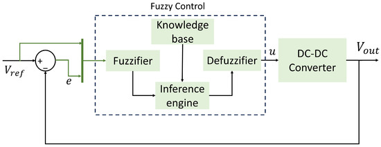
Figure 6 illustrates the block diagram of the fuzzy controller operating in closed-loop configuration with the DC-DC converter in buck or boost mode of operation. It can be noted that, for both modes of operation, the controller has two inputs, consisting of and , which are highlighted in green in the figure.
Figure 6.
Block diagram of the fuzzy control in a closed loop with the DC-DC bidirectional converter.
The fuzzifier maps real-world values into fuzzy sets of the form:
where denotes the inputs to the controller, defined in the universe of discourse , and is the membership function of the fuzzy set . For both converters, the variables e and are the inputs; thus, . These variables, with their real-world values, are mapped to the linguistic variables and with linguistic values and , respectively. One of the main challenges in fuzzy logic control is defining the membership rules, as there is no systematic approach for this task. Heuristic methods such as Particle Swarm Optimization (PSO) [51], Invasive Weed Optimization (IWO) [52] and Genetic Algorithms [49] have been applied. However, one of the objectives of this work is to provide engineers and field operators with a straightforward method for designing nonlinear controllers while avoiding the use of mathematical models that are complex to derive and valid only within limited operating regions. Instead, practical knowledge and operator expertise can be used to derive the membership functions.
Figure 7 shows the membership functions describing the degree of certainty that the “voltage difference” possesses for each linguistic value. It can be observed that three simple functions are sufficient to map the input variable into the fuzzy space.
Figure 7.
Input membership functions for the first input; fuzzy control in buck mode of operation.
Figure 8 shows the membership functions describing the degree of certainty that the “voltage reference” possesses for each linguistic value. Five Gaussian membership functions, evenly distributed between 0 and 400 volts, were used.
Figure 8.
Input membership functions for the second input; fuzzy control in buck mode of operation.
The knowledge base contains the set of linguistic rules that map the inputs to the outputs. These rules are of the form:
with
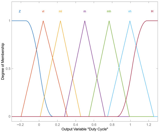
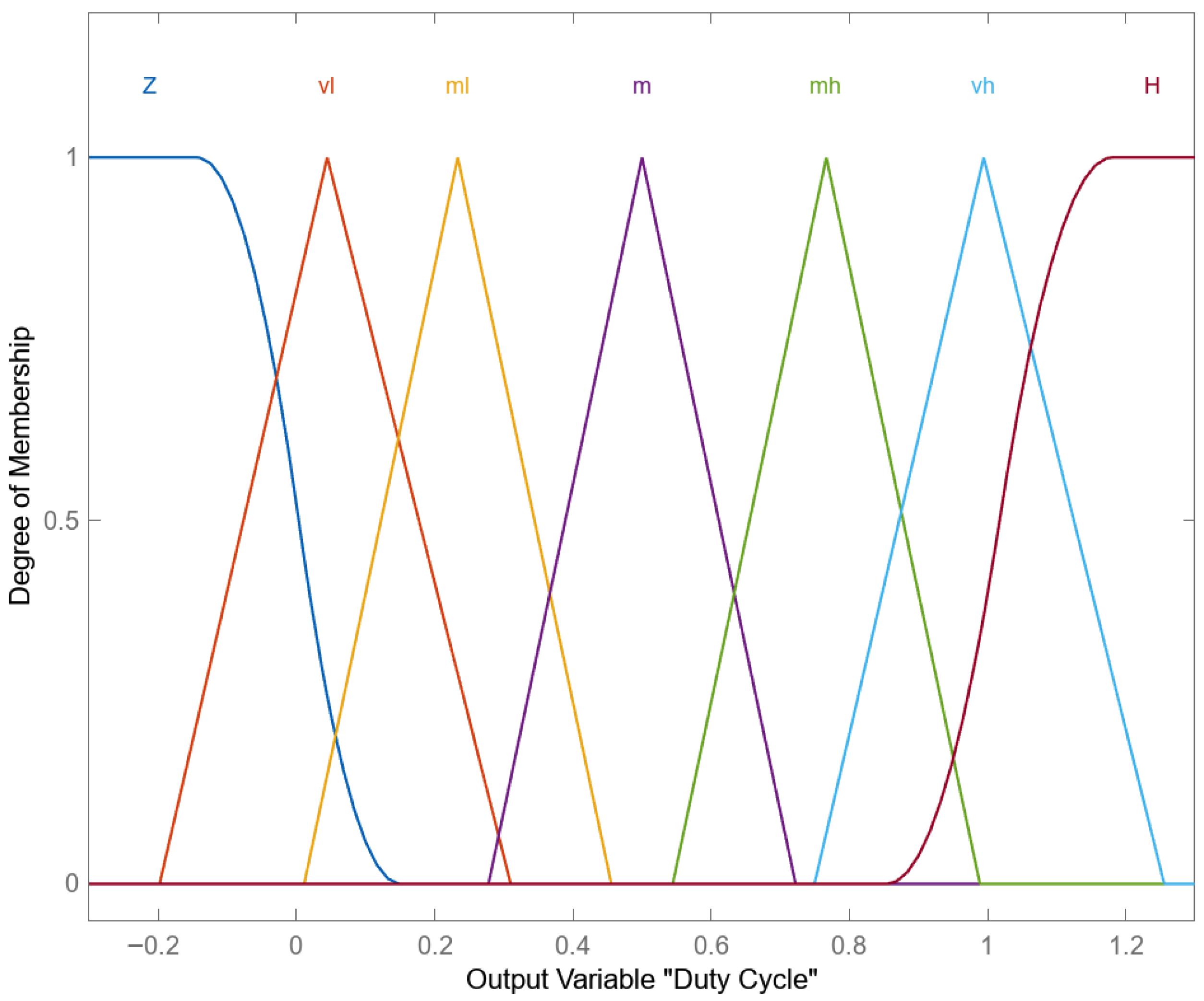
where denotes the outputs from the controller defined over the universe of discourse , and is the membership function for the fuzzy set . The control action u is the single output variable with the linguistic variable and linguistic values . Figure 9 shows the output membership functions for the buck mode of operation. Five triangular functions evenly distributed between −0.2 and 1.2 are used. Additionally, s and z shaped functions enclose the triangular ones, as seen in the figure.
Figure 9.
Output membership functions for fuzzy control in buck mode of operation.
The inference engine is the reasoning component. It reaches conclusions based on inference from the fuzzy rules and inputs. All possible rules are evaluated in parallel to estimate the degree of support for each one. This is an important feature of fuzzy control, as it provides a smooth transition between control regions instead of sharp switching between modes. However, this also adds computational complexity to the algorithm. Once the degree of support has been determined, the implication operator is applied to the output fuzzy sets. Aggregation of the sets is performed before defuzzification [53,54]. The defuzzifier maps the implicated and aggregated fuzzy sets to a real-world value. The Center of Gravity (COG) method was employed, which is defined as follows:
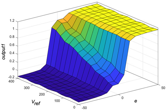
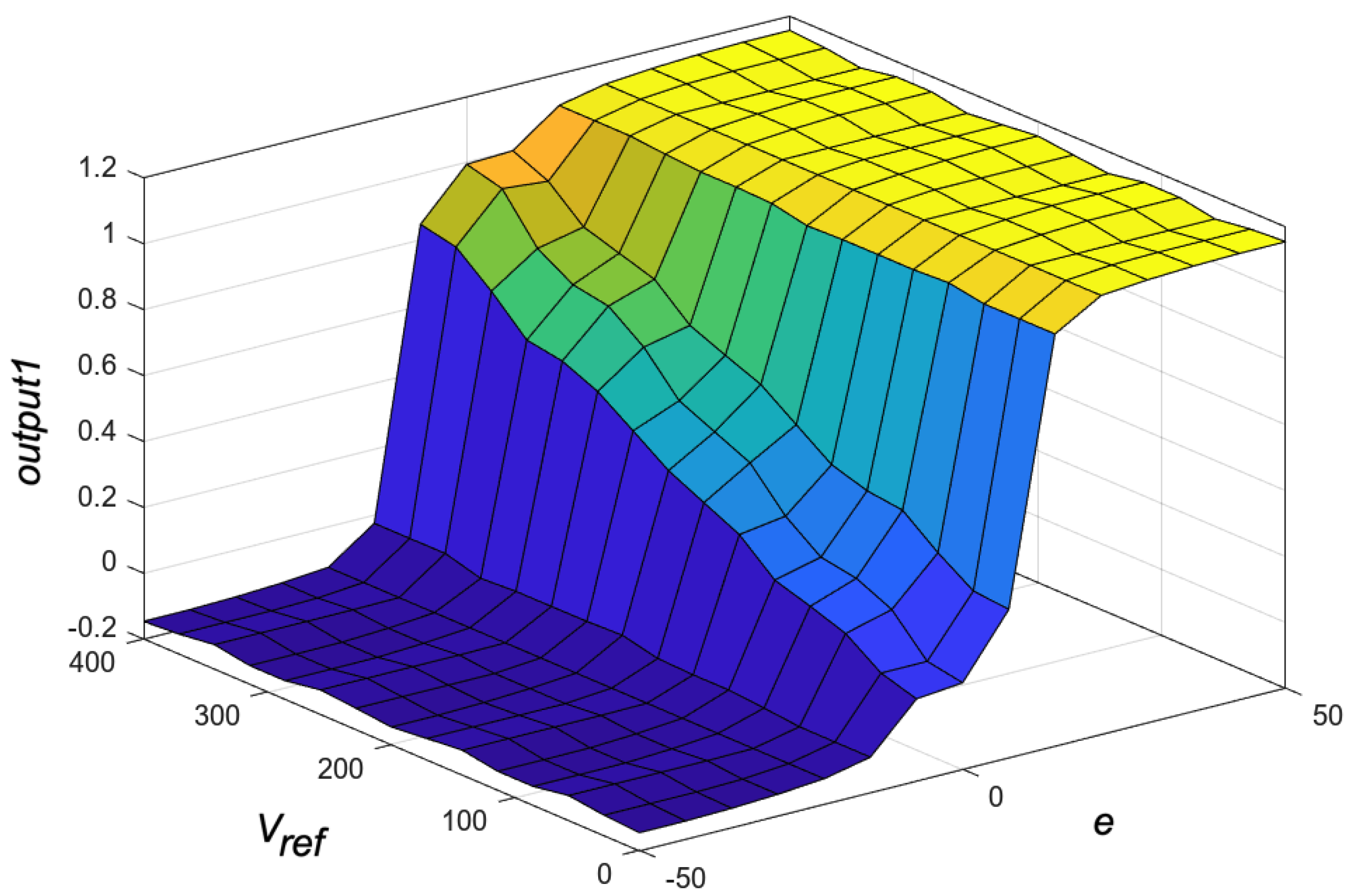
where R is the number of rules, is the center of area of the membership function, and the integral of represents the area under the membership function for the specified linguistic value and fuzzy set. The relationships between the inputs and outputs defined by the inference rules are presented in Table 4. There are 15 possible combinations for the two inputs, “” and “”. The seven output membership functions are assigned to these combinations according to the observed behavior of the converter. For very low negative and very high positive values of the input “”, the output is zero “” or high “”, regardless of the value of the second input “”. For values of “” that fall within the membership function defined as zero, five output membership functions describe the behavior of the output according to the value of the second input “”. The resulting control surface is shown in Figure 10.
Table 4.
Inference rules for the fuzzy control of the boost converter. Fuzzy set labels and variables are detailed in the text.
Figure 10.
Fuzzy control surface for the converter in buck mode showing the voltage difference e and the Voltage reference in the x and y axes and the output variable Duty Cycle ” in the z axis.
3.2. Fuzzy Control with Converter in Boost Mode of Operation
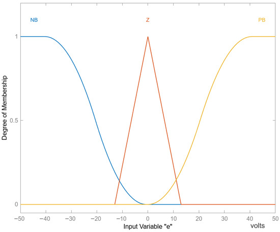
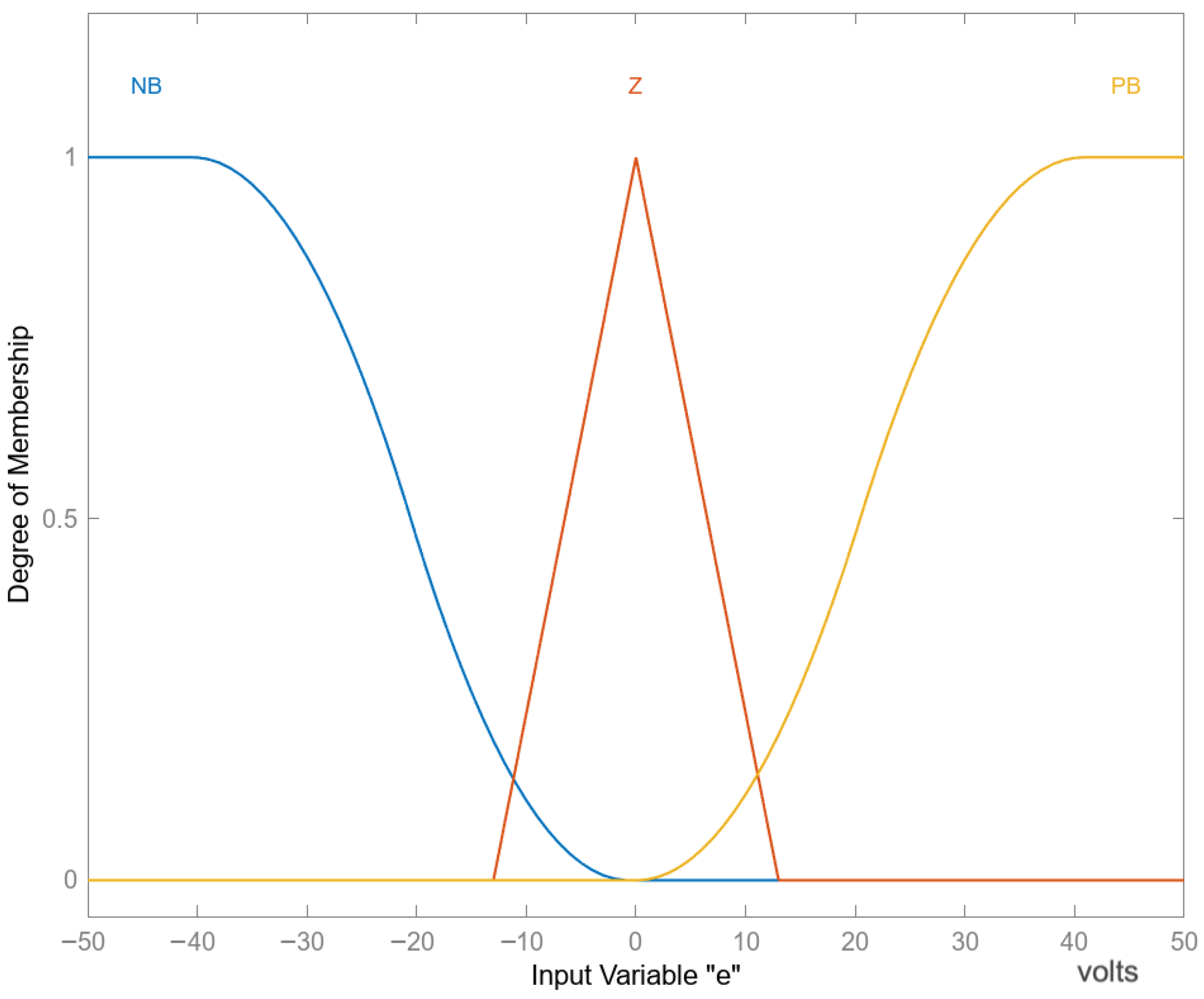
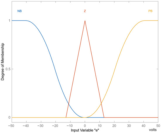
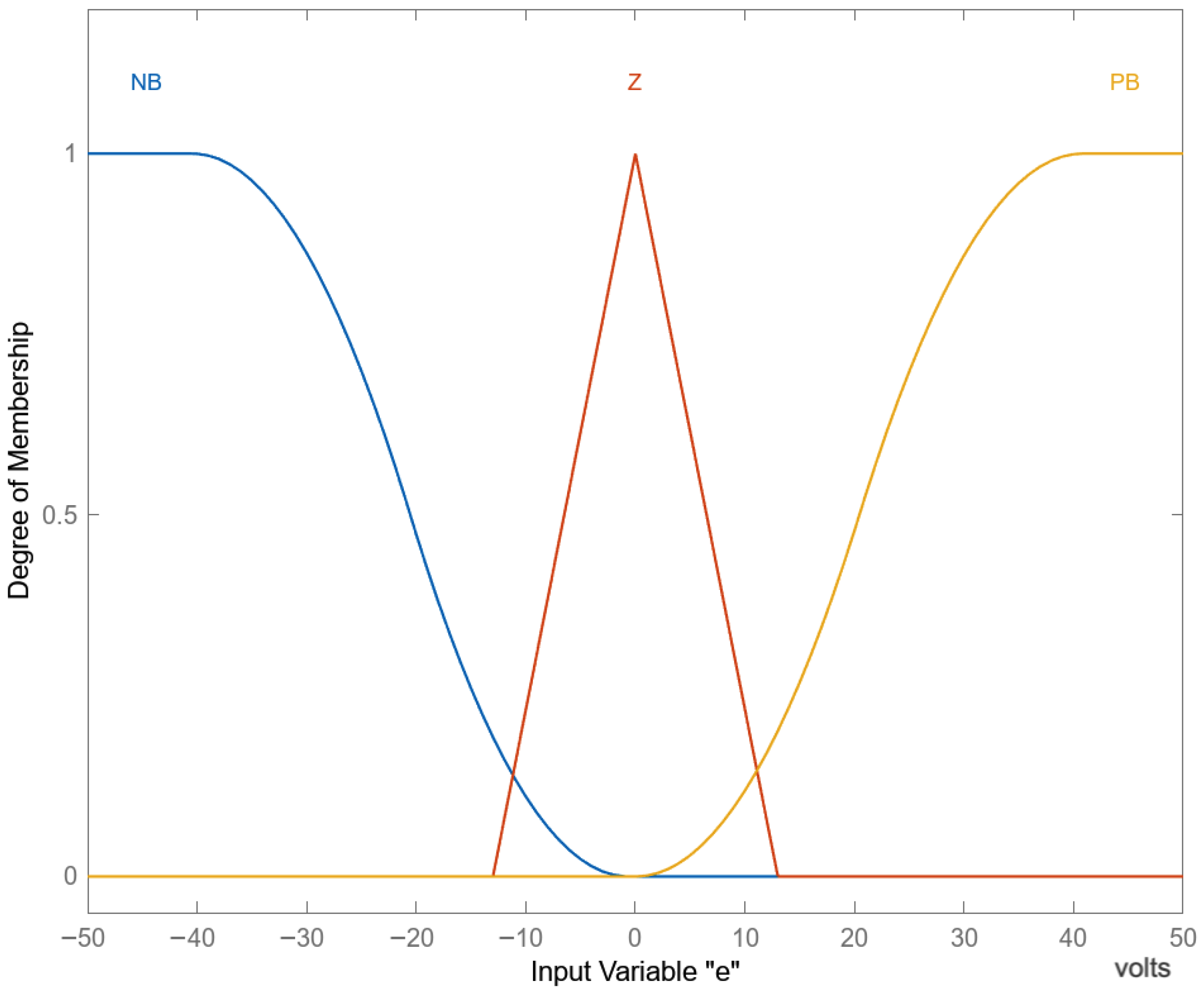
Figure 6 illustrates the block diagram of the fuzzy controller operating in a closed-loop configuration with the DC-DC converter in either buck or boost mode. The analysis of the control-to-output transfer function for the boost converter shows a right-half-plane zero, which leads to unstable behavior. The same inputs and inference rules used for the buck converter are applied to the boost converter. Figure 11 shows the three membership functions for the first input e. They consist of a Z-shaped function, a triangular function and an S-shaped function ranging from −50 to 50 VDC.
Figure 11.
Input membership functions used for fuzzy control in boost mode; variable e.
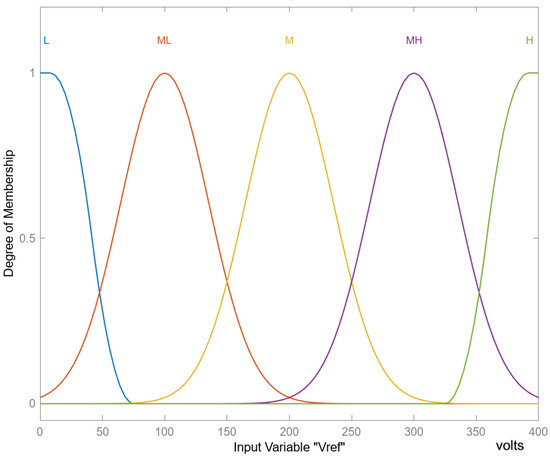
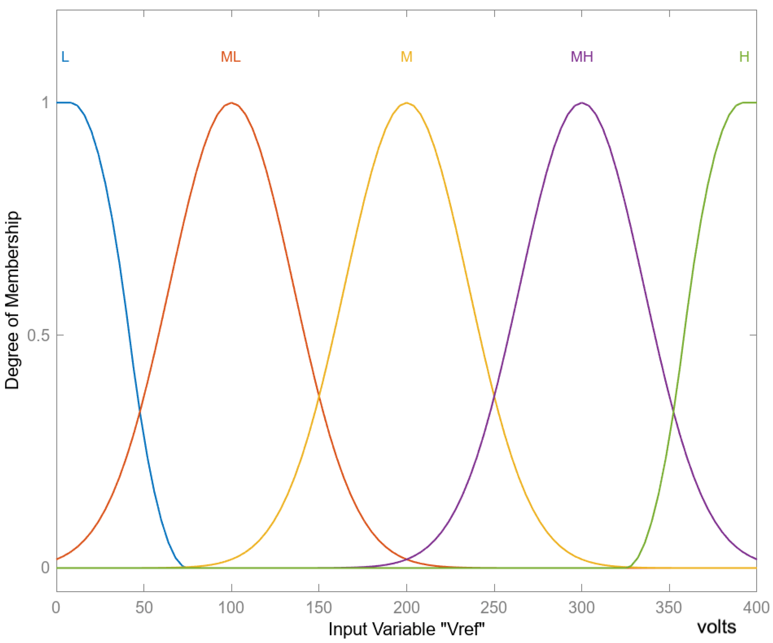
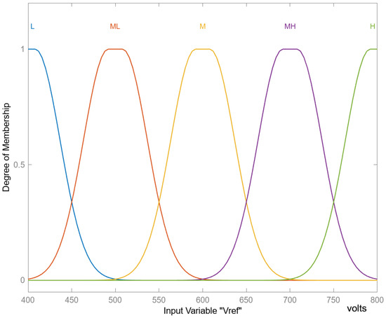
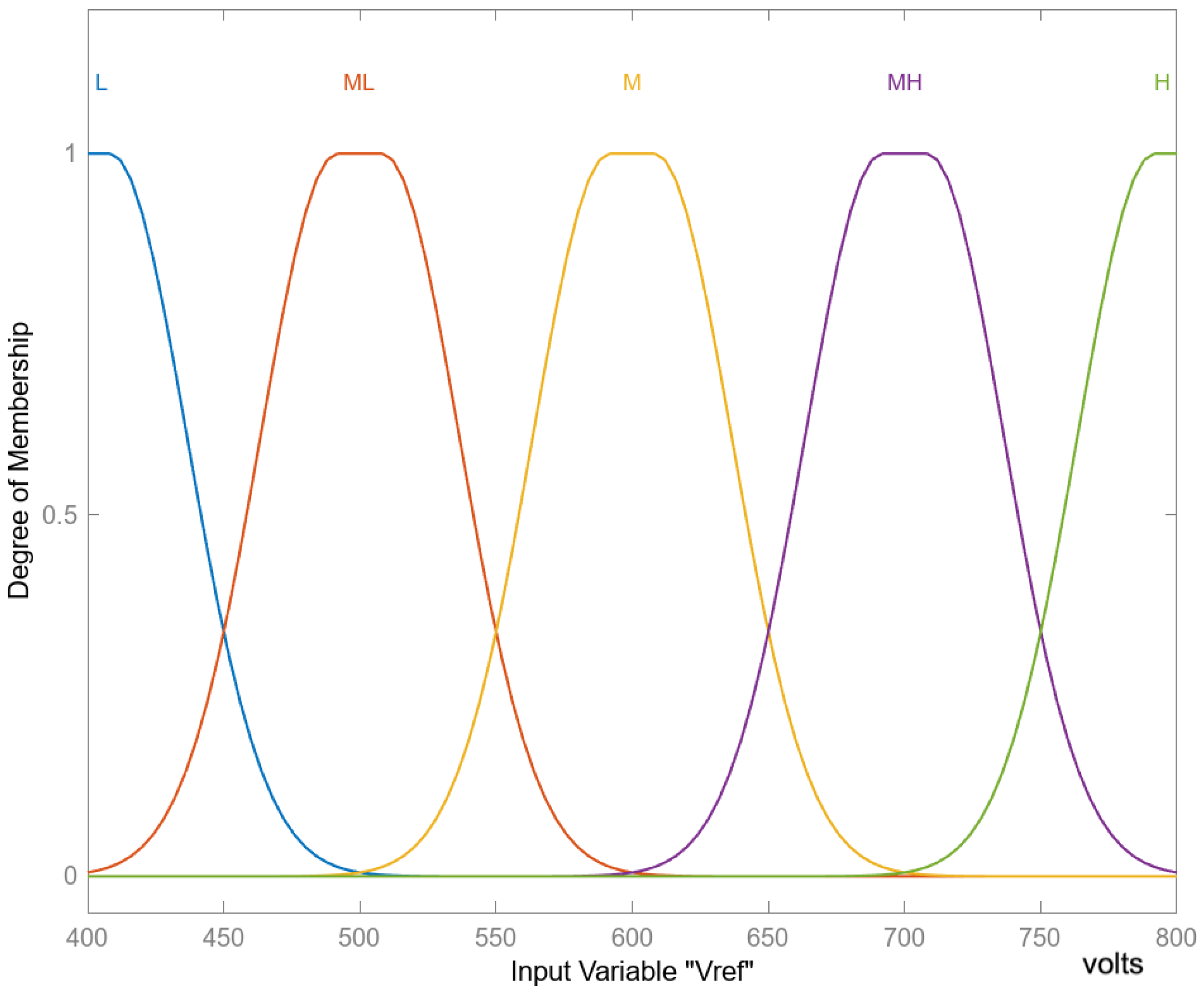
Figure 12 presents the five membership functions for the second input, . These functions were defined by observing the converter’s response to different combinations of input values. For this input, five two-sided Gaussian functions, uniformly distributed between 400 and 800 VDC, were selected, as illustrated in the figure.
Figure 12.
Input membership functions used for fuzzy control in boost mode, variable .
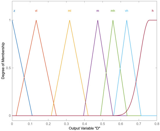
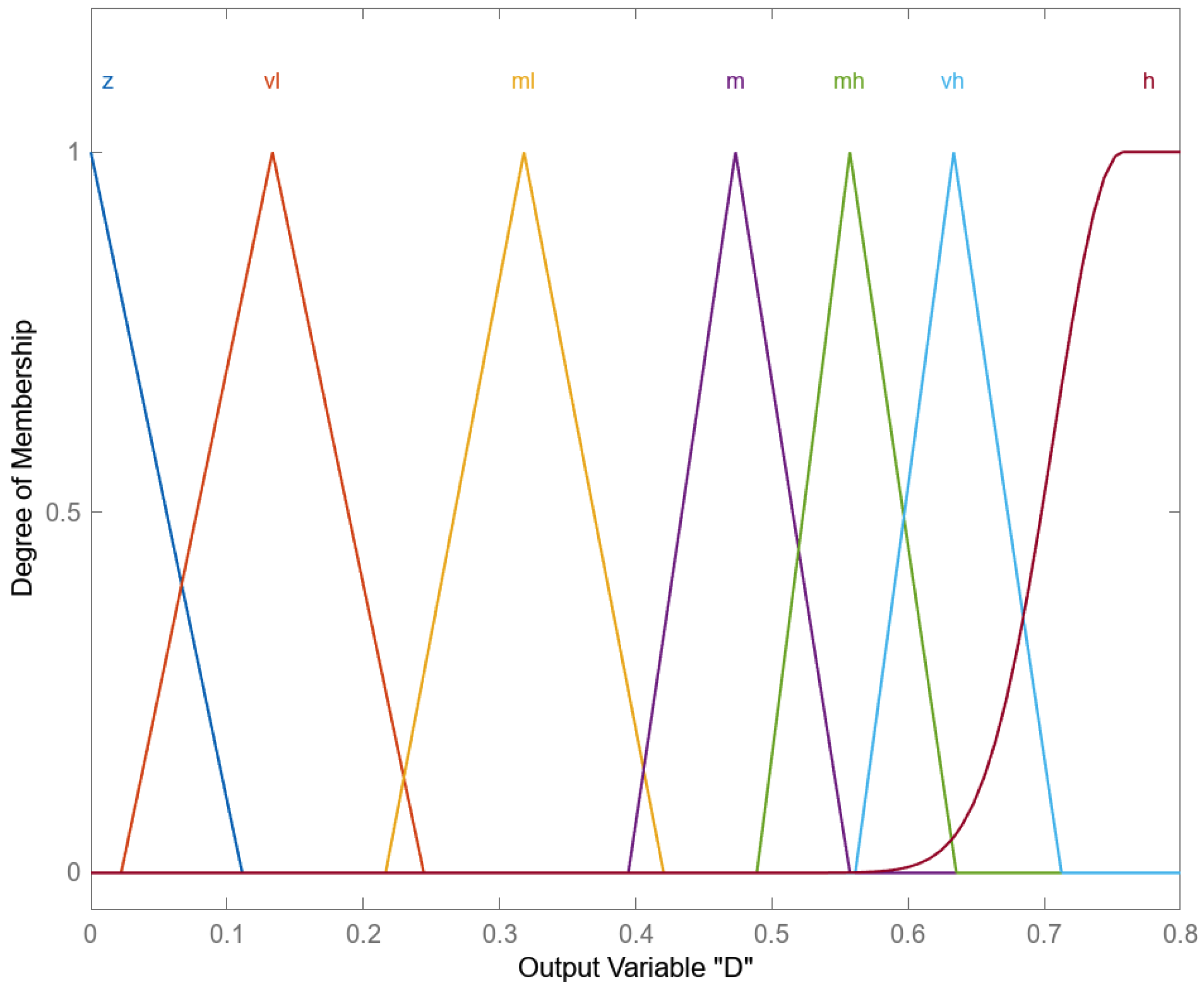
The output membership functions are shown in Figure 13; six triangular functions and one S-shaped function were selected. It can be observed that these functions are unevenly distributed over the range of 0 to 0.8 for the duty factor output “”. This distribution corresponds to the nonlinear behavior of the converter and its inherent instability. The inference rules for both the boost and buck converters are identical and are presented in Table 4.
Figure 13.
Output membership functions for the variable Duty Cycle “D” in Boost mode of operation.
To validate this approach, the bidirectional converter from Section 2 was implemented in Matlab/Simulink using the Simscape functionalities, which provide accurate switching models for power converters.
4. Neural Network Control
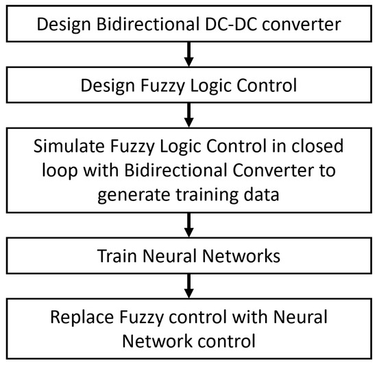
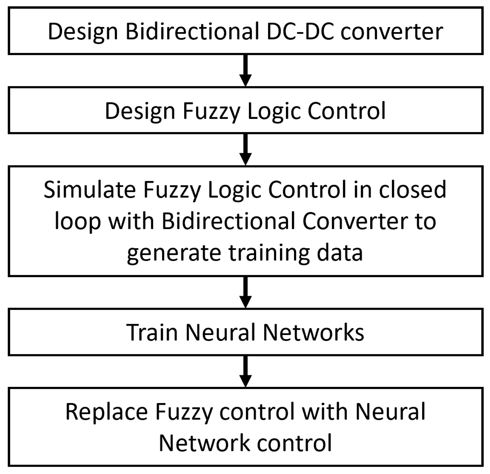
With the aim of improving the execution time of the fuzzy control, the proposed procedure to train the Neural Network is shown in Figure 14. First, the bidirectional DC-DC converter and the fuzzy logic control are designed and validated in a closed loop, as described in the previous sections. Then, this model is used to generate the data required to train the Neural Network. Once the network has been trained and validated, the fuzzy block is replaced with it to control the bidirectional DC-DC converter in a closed loop.
Figure 14.
Simplified block diagram of the proposed approach to generate data for training the neural network and use it as control system for the DC-DC converter.
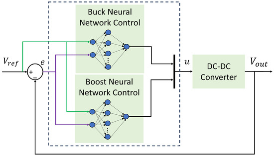
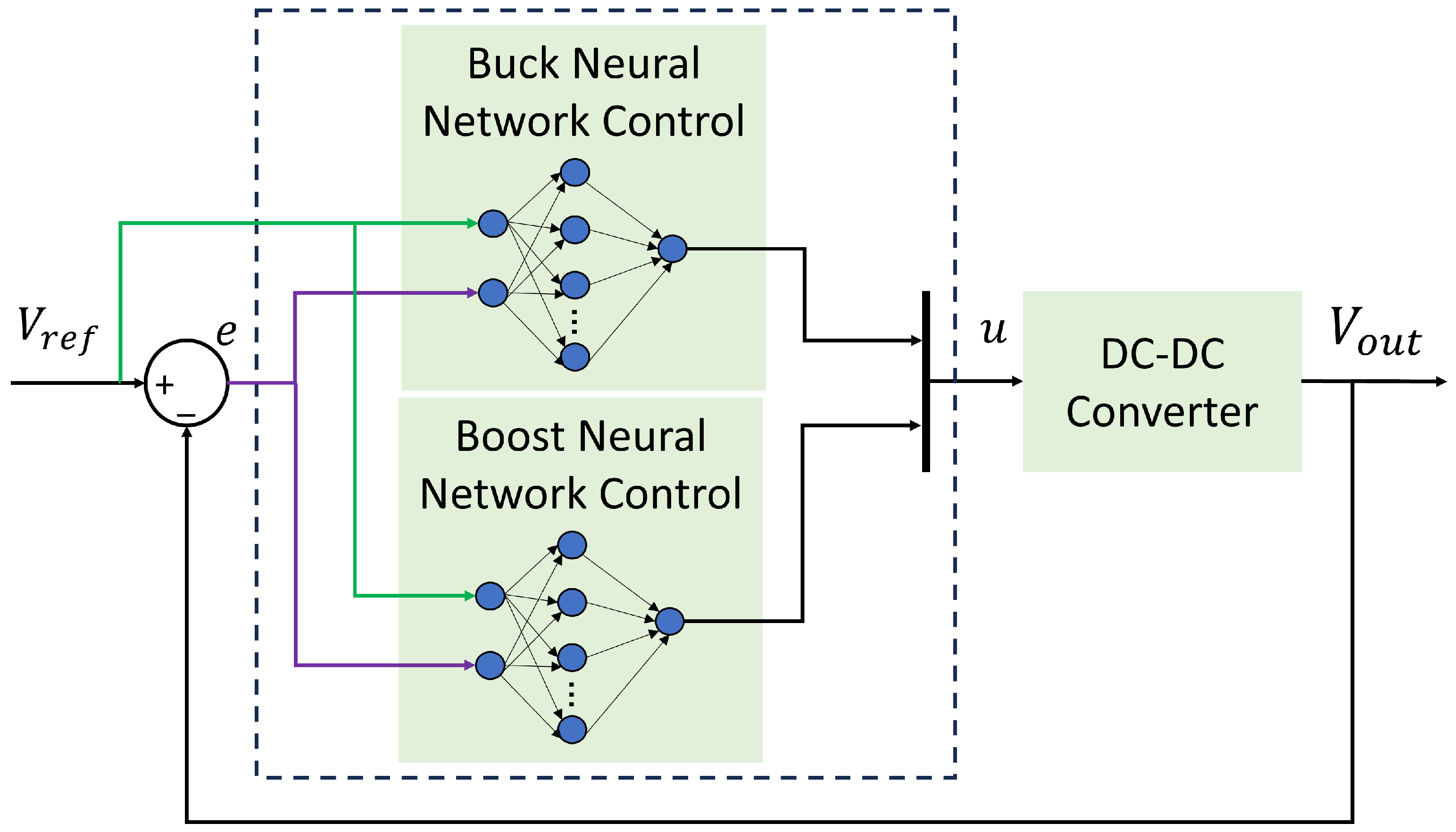
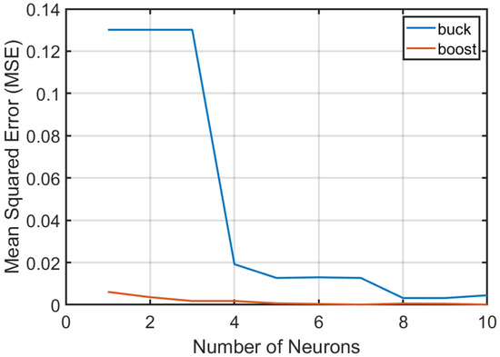
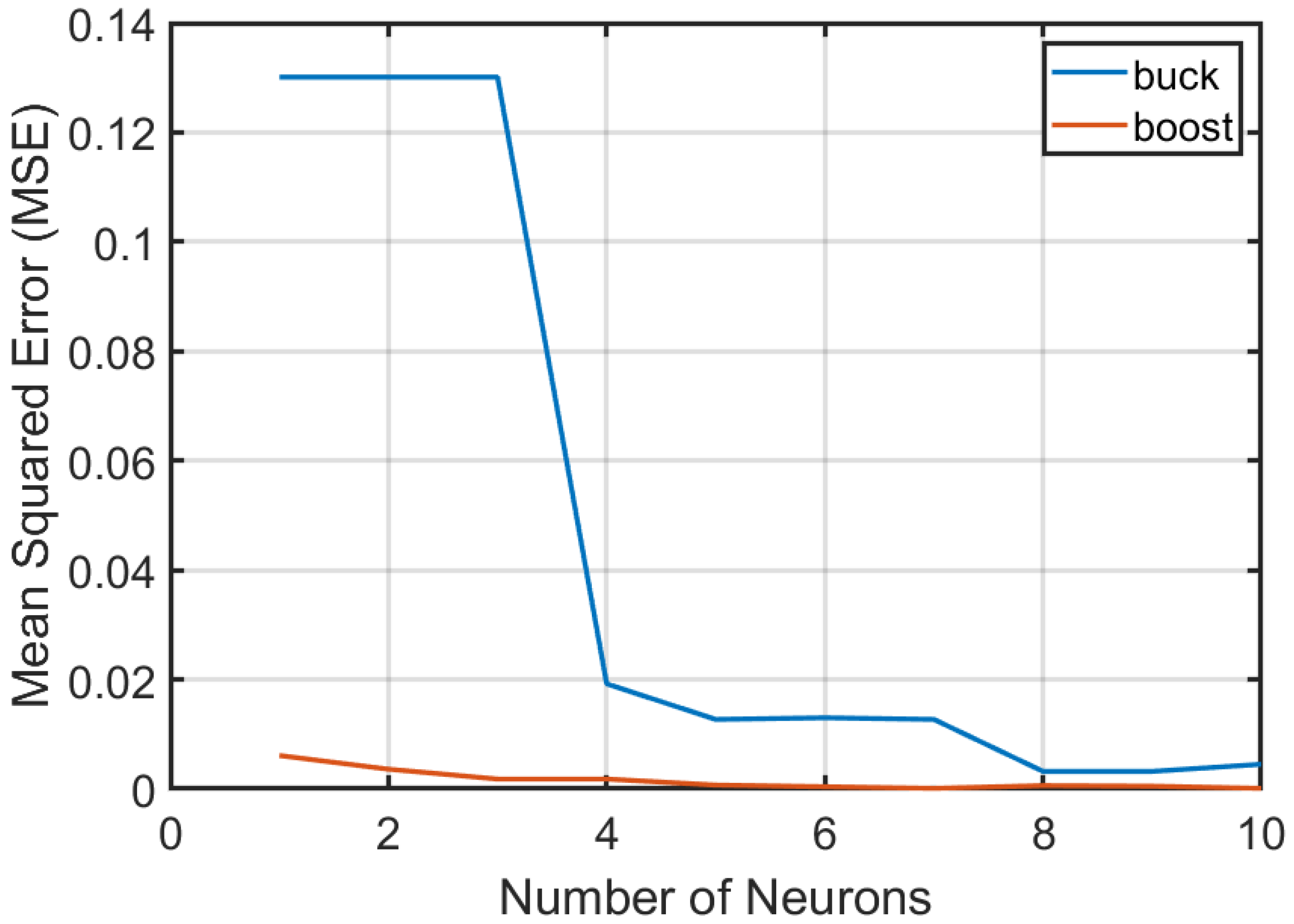
Two independent neural networks are used to control the buck and boost modes. For both networks, the inputs are the reference voltage and the control error, defined as , while the output is the control action u, corresponding to the duty cycle. Figure 15 shows the closed-loop control architecture for both modes. The neural network structure is intentionally simple, representing a trade-off between approximation capability and computational efficiency for real-time FPGA implementation. The network consists of two input nodes, a single hidden layer, and one output neuron. A single hidden layer is used to minimize resource utilization when translating the control from simulation into hardware. The number of neurons in the hidden layer was determined empirically by evaluating configurations ranging from 2 to 15 neurons. Figure 16 presents the mean squared error (MSE) obtained after training in both modes. As a result, a compact architecture was selected, providing sufficient accuracy with minimal hardware resource utilization.
Figure 15.
Block diagram of Neural Network control in a closed loop with the DC-DC bidirectional converter.
Figure 16.
Number of neurons in the hidden layer vs Mean Squared Error (MSE).
4.1. Training Data
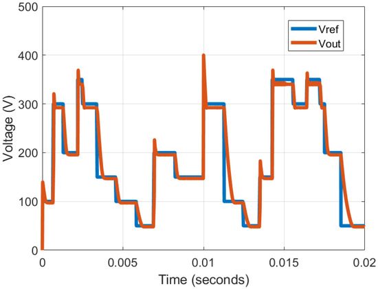
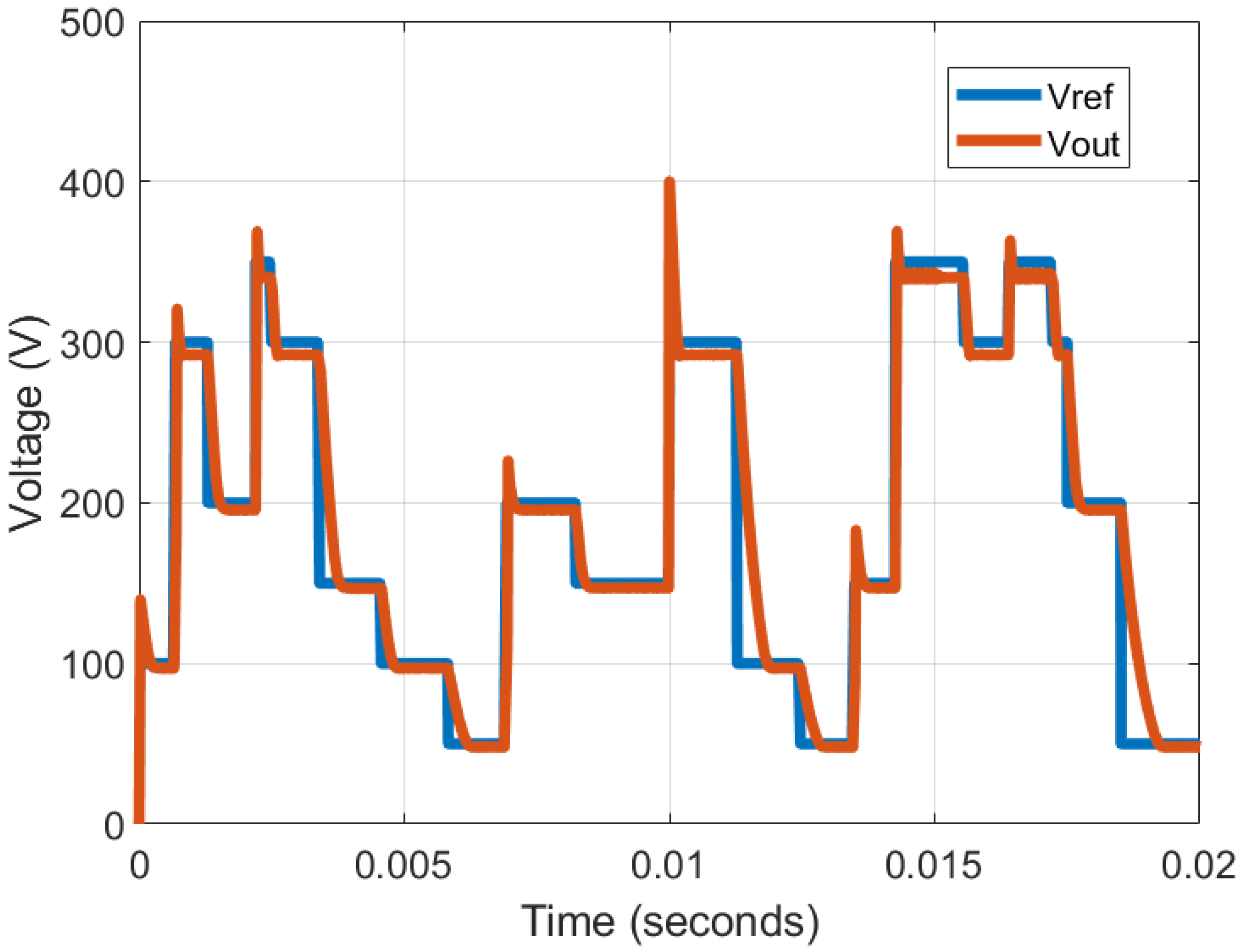
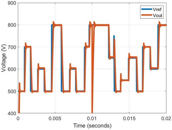
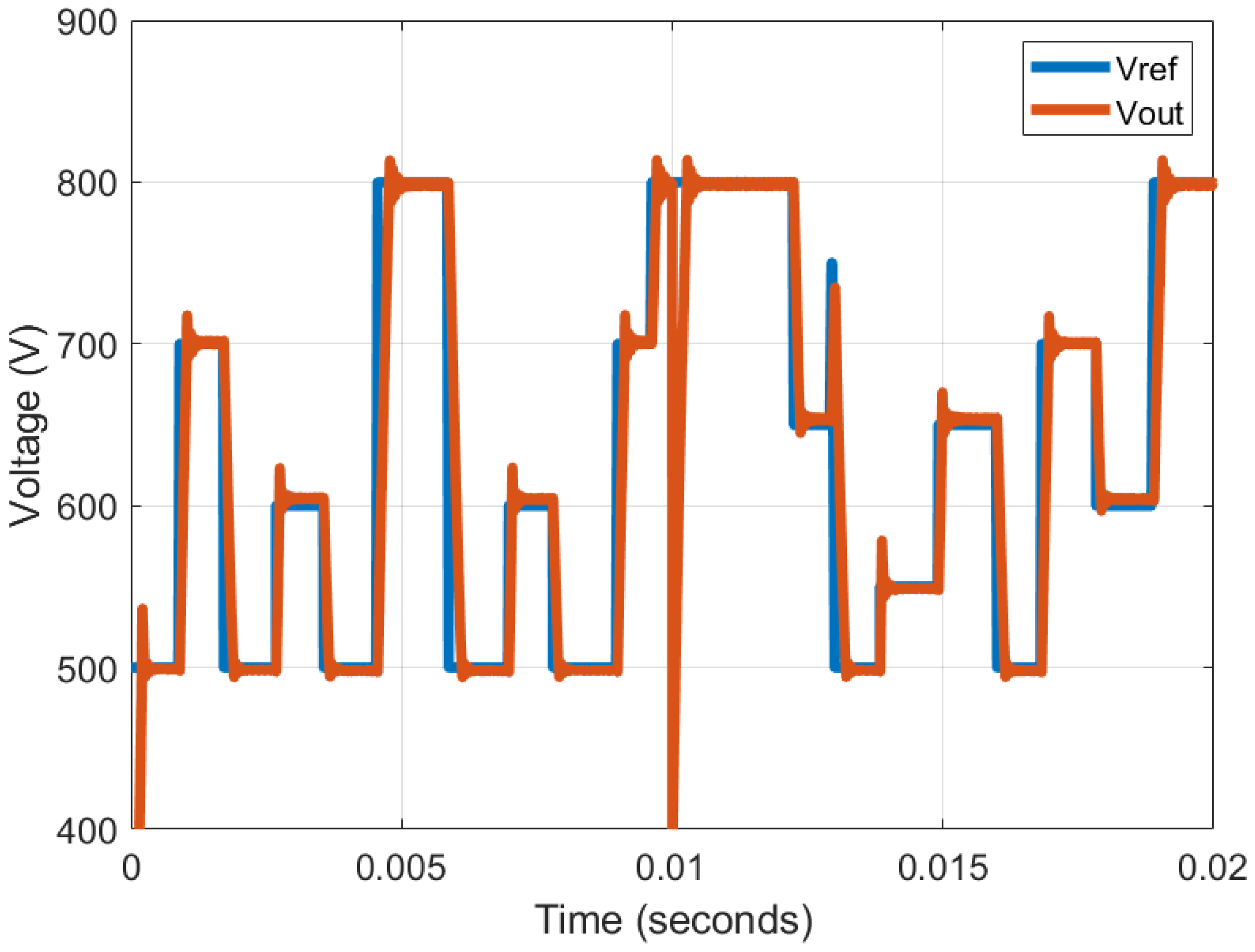
The bidirectional converter was simulated using the setup shown in Figure 6, varying the voltage reference from 50 to 300 VDC for the buck case and from 500 to 800 VDC for the boost case. A total of 2 million observations corresponding to 20 ms sampled at intervals were obtained for each scenario. Figure 17 and Figure 18 show the generated training data for the buck and boost modes of operation, respectively. It can be observed that the output voltage closely follows the reference signal in both forward and reverse modes of operation.
Figure 17.
Training data generated with fuzzy logic control forward and reverse in buck mode of operation.
Figure 18.
Training data generated with fuzzy logic control forward and reverse in boost mode of operation.
4.2. Neural Network Training
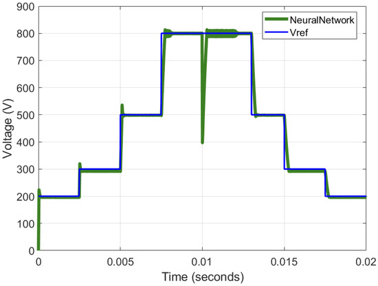
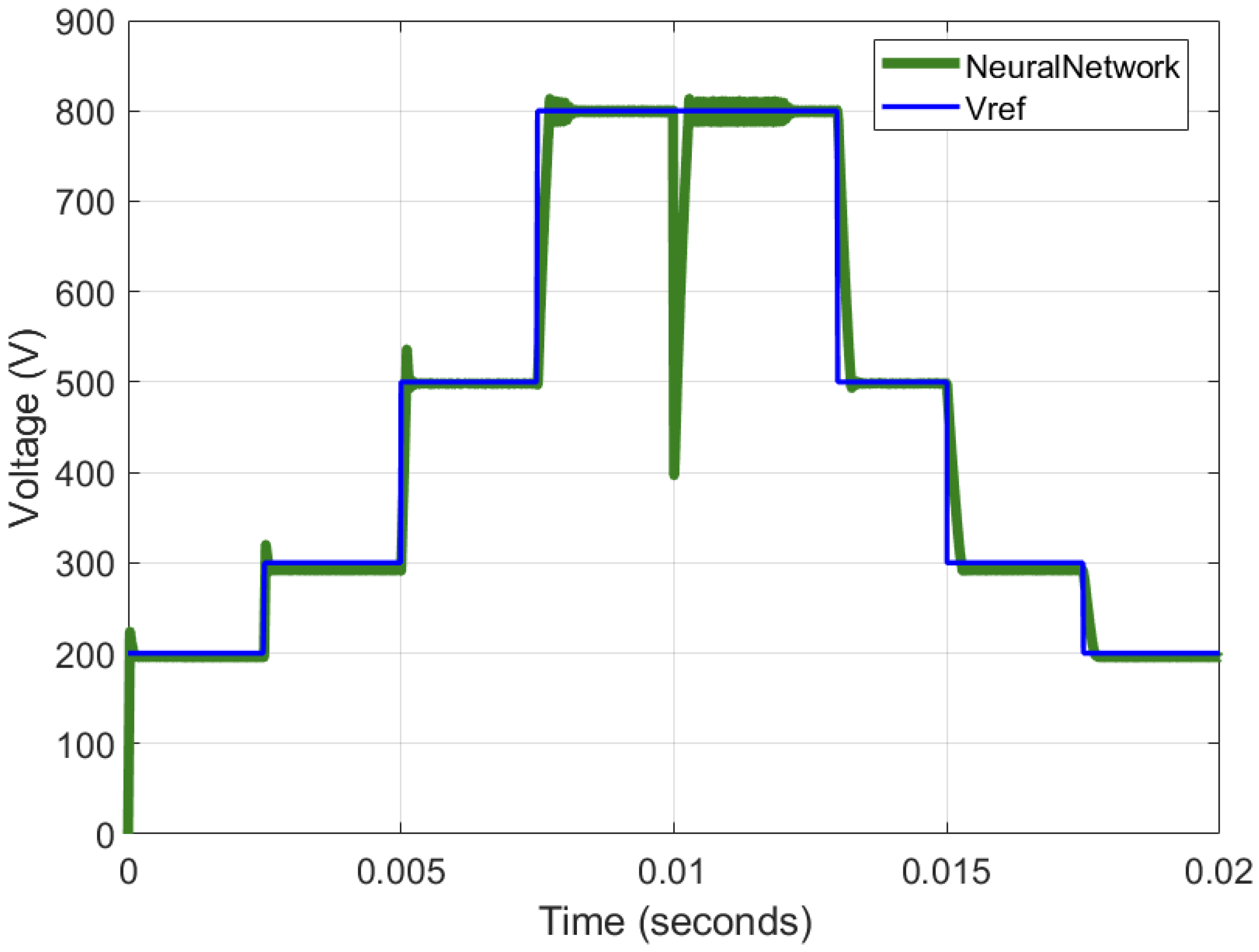
Two datasets were obtained and subsequently used to train two neural networks: one for buck control and one for boost control. Both datasets were divided into 80% for training and 20% for validation. The same two inputs were used for both networks: the voltage difference e and the reference voltage. The duty cycle u is the only output for both networks. Neural networks with a single hidden layer have been shown to effectively control DC–DC converters at high switching frequencies in real time [20,27,37]. The limited-memory Broyden–Fletcher–Goldfarb–Shanno (L-BFGS) algorithm was used as the training method to minimize the Mean Squared Error (MSE). This is a quasi-Newton method used to solve nonlinear optimization problems [55]. The ReLU activation function was selected due to its favorable performance, simplicity, and suitability for hardware implementation. The only parameter left for optimization is the number of neurons in the hidden layer. Therefore, different networks were trained by varying the number of neurons from 2 to 15. Figure 16 shows the Mean Squared Error (MSE) obtained using the test data for different numbers of neurons in the buck and boost control modes. The MSE decreases sharply after five neurons for the buck case and after three neurons for the boost mode. Therefore, seven and five neurons were selected for the hidden layer in the buck and boost networks, respectively. Figure 19 shows the results of the neural networks controlling the output voltage of the bidirectional DC–DC converter in both buck and boost modes. The output voltage closely follows the reference voltage in forward, reverse, buck, and boost modes of operation. It can be observed that the output closely resembles that of the fuzzy control. A quantitative comparison of the results is summarized in Section 5.
Figure 19.
Neural Network control of bidirectional DC-DC converter from a fuzzy logic approach.
5. Experimental Validation and Discussion
5.1. Model Base Design
The proposed methodology was implemented using MATLAB R2023a with their corresponding Simulink and Simscape utilities, which provides a flexible platform for real-time control development and hardware-oriented validation. That framework is inherently parameterizable and scalable. The bidirectional DC-DC converter model implemented in MATLAB/Simulink is defined using configurable parameters, which can be easily adjusted to implement different converter specifications without modifying the overall control structure. Similarly, the control methodology allows for flexibility in the design of the neural network, including the number of neurons, activation functions, and training dataset characteristics. The fuzzy-logic-based data generation process can be adapted to different operating conditions or extended to alternative converter topologies. Therefore, the proposed approach is not limited to the specific case study presented in this work, but can be used as a general framework for the design and validation of intelligent control strategies in power electronic systems.
The proposed workflow makes use of MATLAB/Simulink resources for system modeling, validation, and automatic code generation. The trained neural networks are converted into fixed-point representations and automatically translated into synthesizable VHDL code using the Vivado tool, enabling efficient implementation on the FPGA. Although Processor-in-the-Loop (PIL) is commonly used for validating control algorithms on embedded processors, the target platform in this work is a programmable logic device; therefore, an FPGA-in-the-Loop (FIL) approach is adopted, allowing for direct execution of the control algorithm in hardware.
5.2. Hardware/Software Validation Platform
In order to provide a clear description of the proposed system, the hardware/software validation platform is formalized in this sub-section. This formalization includes the definition of functional requirements, design specifications, physical and implementation constraints, component interfaces and deployment, organized in an itemized form.
5.2.1. Functional Requirements
- The system aims to regulate the output voltage of a bidirectional DC-DC converter, which is part of the powertrain in an EV to control the power flow between the energy source and the load.
- The system shall operate in both buck and boost modes, enabling bidirectional power flow between the energy source and the load.
- The converter control will be based on a lightweight Neural Network algorithm for hardware implementation.
- A fuzzy logic controller shall be first used to generate a dataset of control actions under closed-loop operation, which will be further used for neural network training.
- The system shall support validation through a Simulink-based FPGA-in-the-loop framework.
5.2.2. Design Specifications and Additional Considerations
- The converter shall operate under electrical ranges corresponding to EV applications such as 400 VDC, I/O voltage range of 200–800 VDC, and support wide bandgap devices switching frequency of 500 kHz.
- The system should achieve a settling time below 250 μs with a maximum overshoot of 5.0%.
- The system should achieve improved performance when compared to the benchmark PID control method.
- Stable operation must be observed in both, buck and boost modes, under the evaluated conditions in simulation.
- The system operates in a closed-loop embedded environment without external network connectivity; therefore, security considerations are limited in this context.
5.2.3. Physical and Implementation Constraints
- The power stage and the DC-DC converter control are modeled in Simulink and validated using an FPGA-in-the-loop methodology.
- Since the system shall operate at a high switching frequency of 500 kHz, constraints on control timing and hardware implementation are imposed.
- The control algorithm is deployed on an FPGA platform with finite computational and memory resources, using efficiently available resources, including LUTs, flip-flops, BRAM, and DSP blocks.
5.2.4. Component Interfaces and Deployment
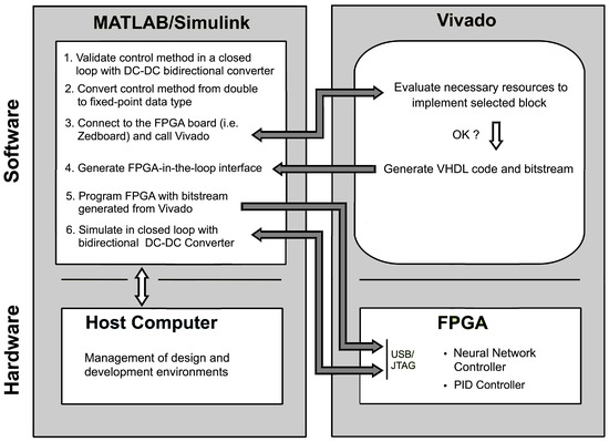
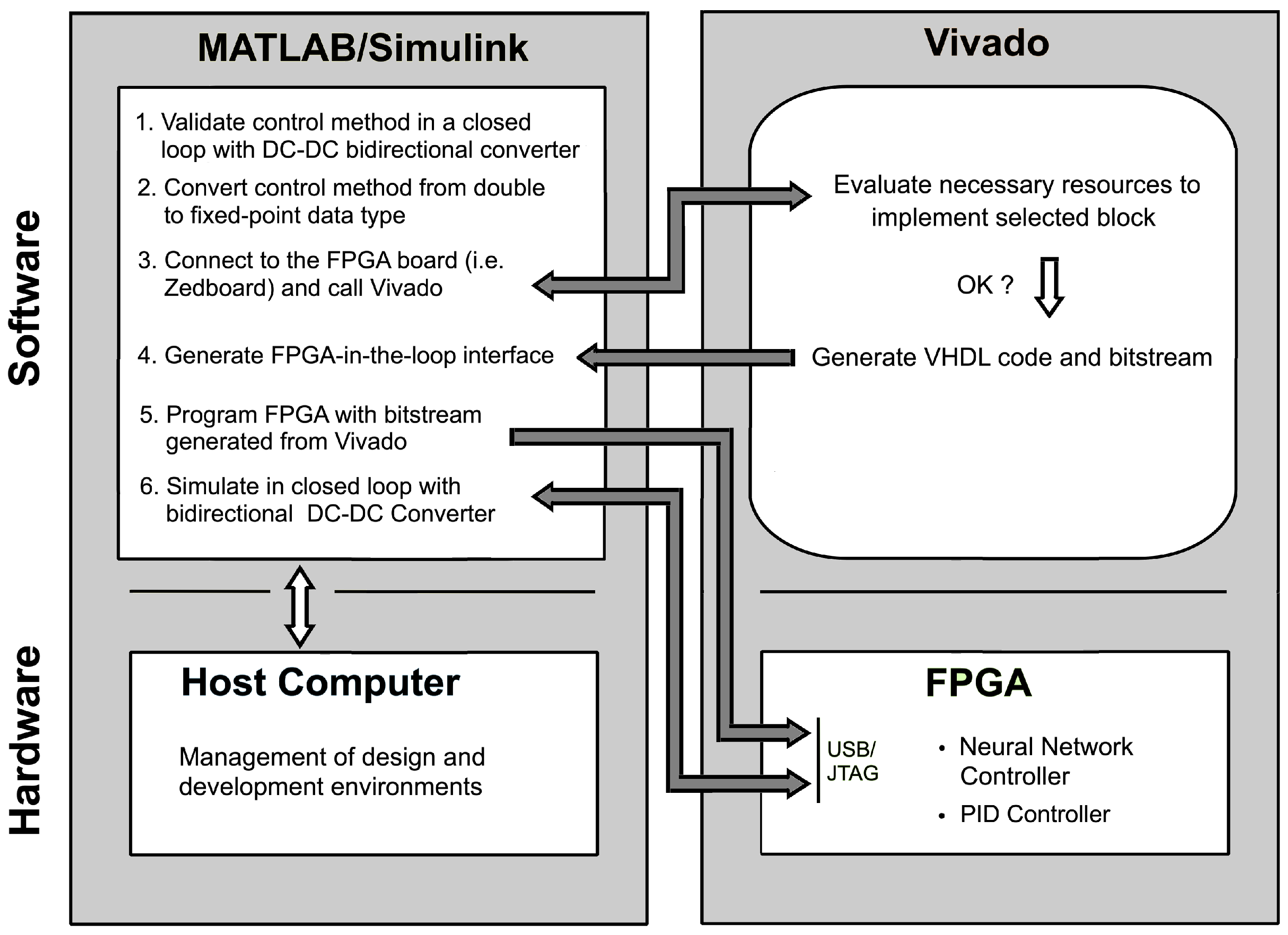
Figure 20 shows a block diagram of the system detailing hardware, software, design and development environments, interfaces and data flow. A Simulink-based environment running in a laptop computer is used as simulation and validation platform hosting the Bidirectional DC-DC Converter Model, while Vidado is used for deployment of the Neural Network controller in a closed loop. This structured formalization provides a clear definition of the system, reducing ambiguity and facilitating reproducibility of the proposed approach.
Figure 20.
Block diagram of FPGA-in-the-loop validation procedure for the neuro-fuzzy control. The arrows represent the dataflow from SIMULINK to VIVADO for generating VHDL code and bitstream. Then, the FPGA board is connected for deployment of the NN controller in closed loop.
5.3. FPGA-in-the-Loop Description
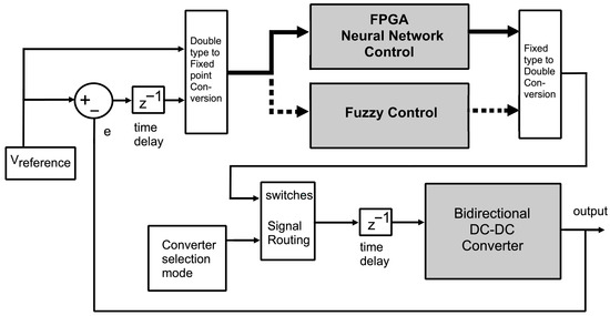
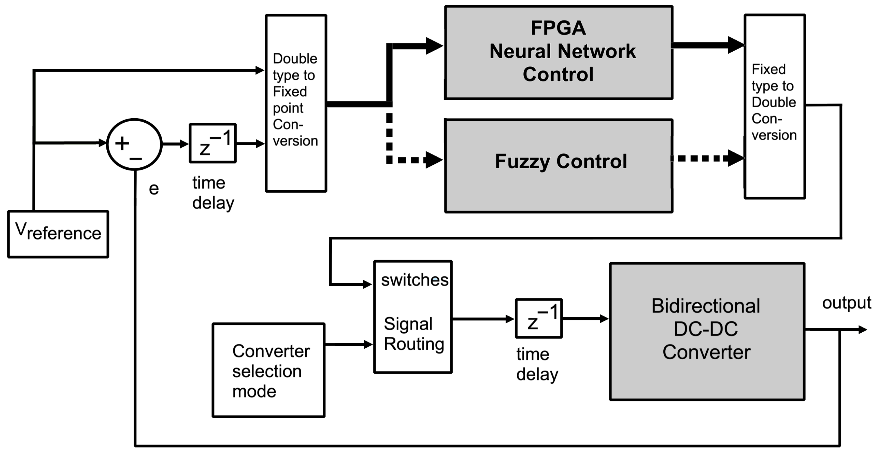
Figure 21 shows a block diagram of the FPGA operating in a closed loop. The neural network controller was implemented on an FPGA and evaluated using a FIL setup. After the neural networks were trained and validated, the data representation was converted from double precision to fixed-point format. The inputs were encoded as signed signals with a 31-bit word length and a 20-bit fractional length, while the outputs were encoded as unsigned signals with a 31-bit word length and fractional lengths of 29 and 31 bits for the buck and boost duty cycles, respectively. Subsequently, VHDL code was generated using the Vivado 2022.1 synthesis tool. The FPGA employed was a Xilinx XC7Z020-1CLG848C Zynq-7000 AP SoC. The next step was to generate a FIL interface to enable communication between the controller implemented on the FPGA and the converter model running on the computer. MATLAB/Simulink was used to generate this interface, which replaced the control block in the simulation and established a communication channel between the neural network controller on the FPGA and the bidirectional converter model on the computer. The high-fidelity model estimates the state of the converter and compares it with the desired output . Next, both signals, and e, are converted into fixed-point representations and they are fed into the converter to update its state. The output is converted into fixed-point representation and sent from the PC to the FPGA. There, the embedded Neural Network estimates the appropriate duty cycle D, and generates the appropriate control action, which is sent back in a closed loop. This procedure is summarized in Figure 21.
Figure 21.
Block diagram of FPGA-in-the-loop validation platform. The fuzzy control is first used in closed loop as indicated by the dashed line. Once the neural network has been trained and validated, it replaces the fuzzy control following the solid line.
5.4. Results
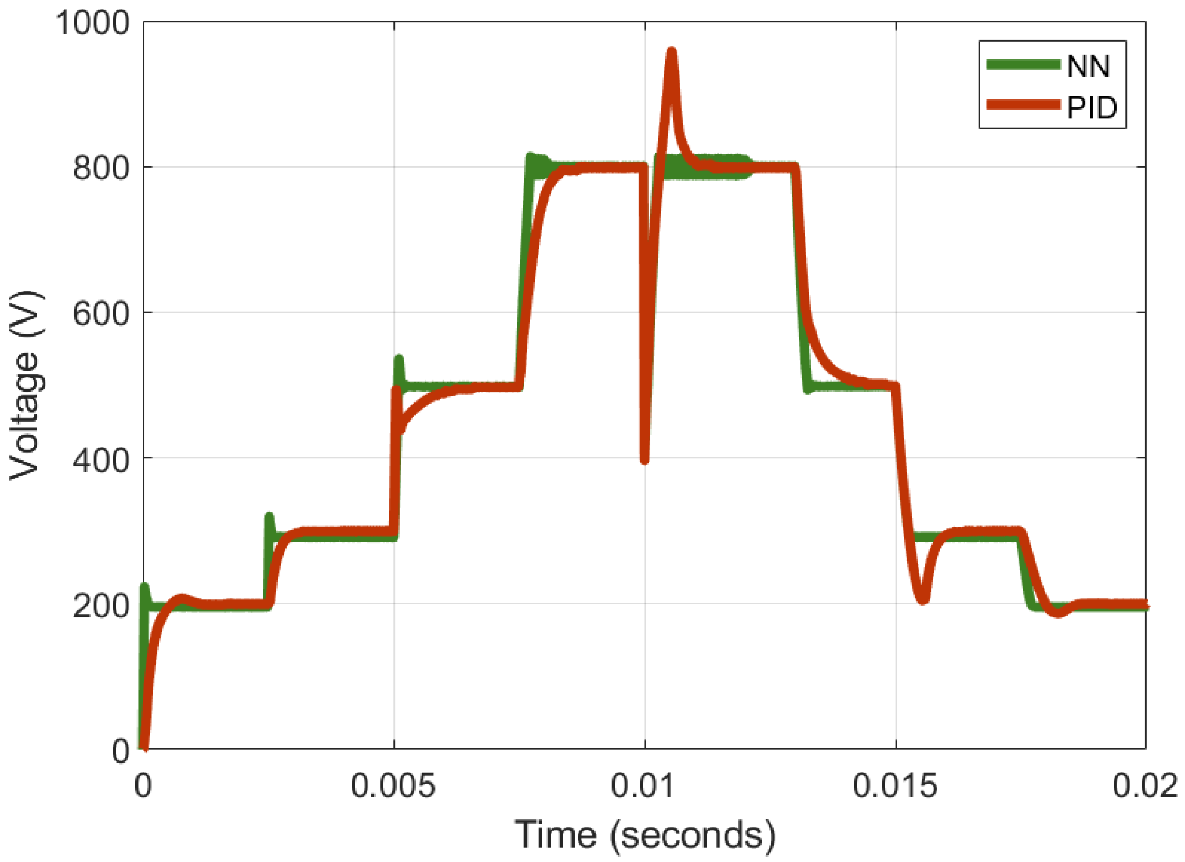
This section presents the results obtained from a comparative evaluation of the PID and neural network controllers implemented within the described FIL scheme. The design details of the PID controller are provided in Section 2.3. Figure 22 shows the performance results of both control strategies. As observed, the neural network controller outperforms the PID controller, exhibiting reduced overshoot and a faster transient response. Additionally, the Root Mean Square Error (RMSE) was computed between the reference signal and the output voltage for the fuzzy, neural network, and PID controllers. The results are summarized in Table 5.
Figure 22.
Comparison of FIL Neural Network control and FIL PID control.
Table 5.
Summary of RMSE, rise time, settling time and voltage overshoot for step voltage change in boost mode.
Fuzzy control achieves the lowest RMSE of 40.34, followed by neural control with 42.23. The FIL-validated implementations yield RMSE values of 51.13 for the PID controller and 42.47 for the neural network. The rise time, settling time, and execution time for a step change in the voltage reference from 500 to 800 VDC in boost forward mode of operation are summarized in Table 5. Boost mode operation is selected for comparison due to the highly unstable behavior of the converter in this operating mode. Fuzzy control, and consequently neural network control, achieve faster rise and settling times, with minimal voltage overshoot and a lower RMSE.
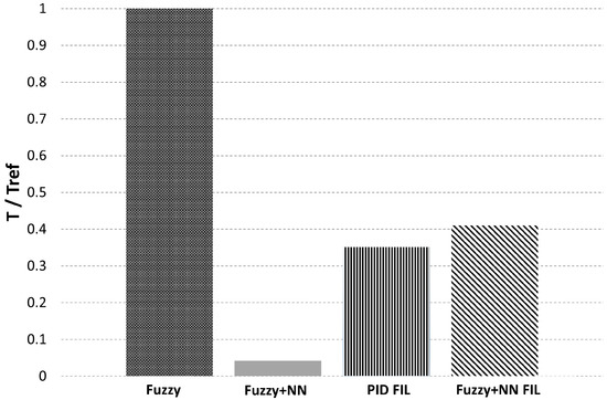
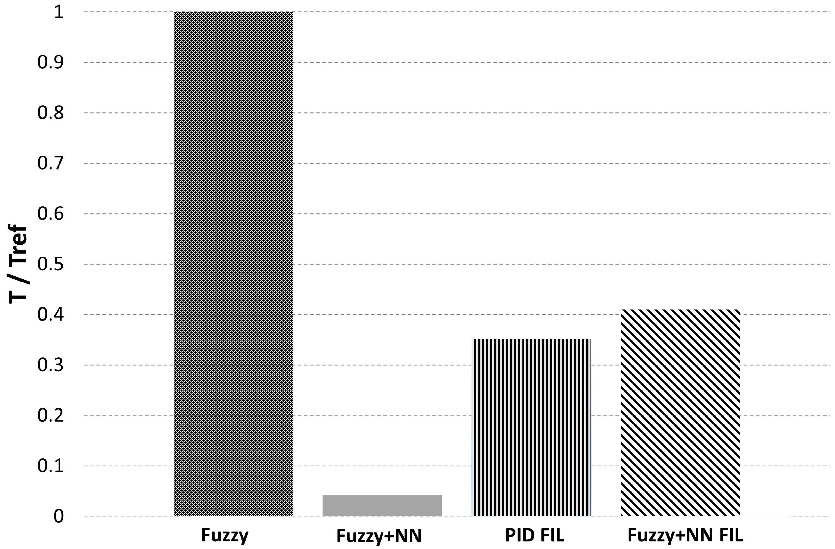
Figure 23 shows the normalized execution time for the fuzzy control, fuzzy+NN, PID with FIL, and fuzzy+NN with FIL. It can be observed that the execution time with the neural networks is reduced to less than 1% compared to running the fuzzy controller alone. When comparing the execution times of the PID controller and the neural network running on the FPGA, a difference of only 5.7% can be observed. Therefore, the proposed approach is close to the PID benchmark in execution time while achieving a reduction in RMSE of 33.7%.
Figure 23.
Normalized execution time.
5.4.1. Efficiency
The efficiency of the converter is defined as the ratio of the output power to the input power [42,47]:
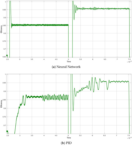
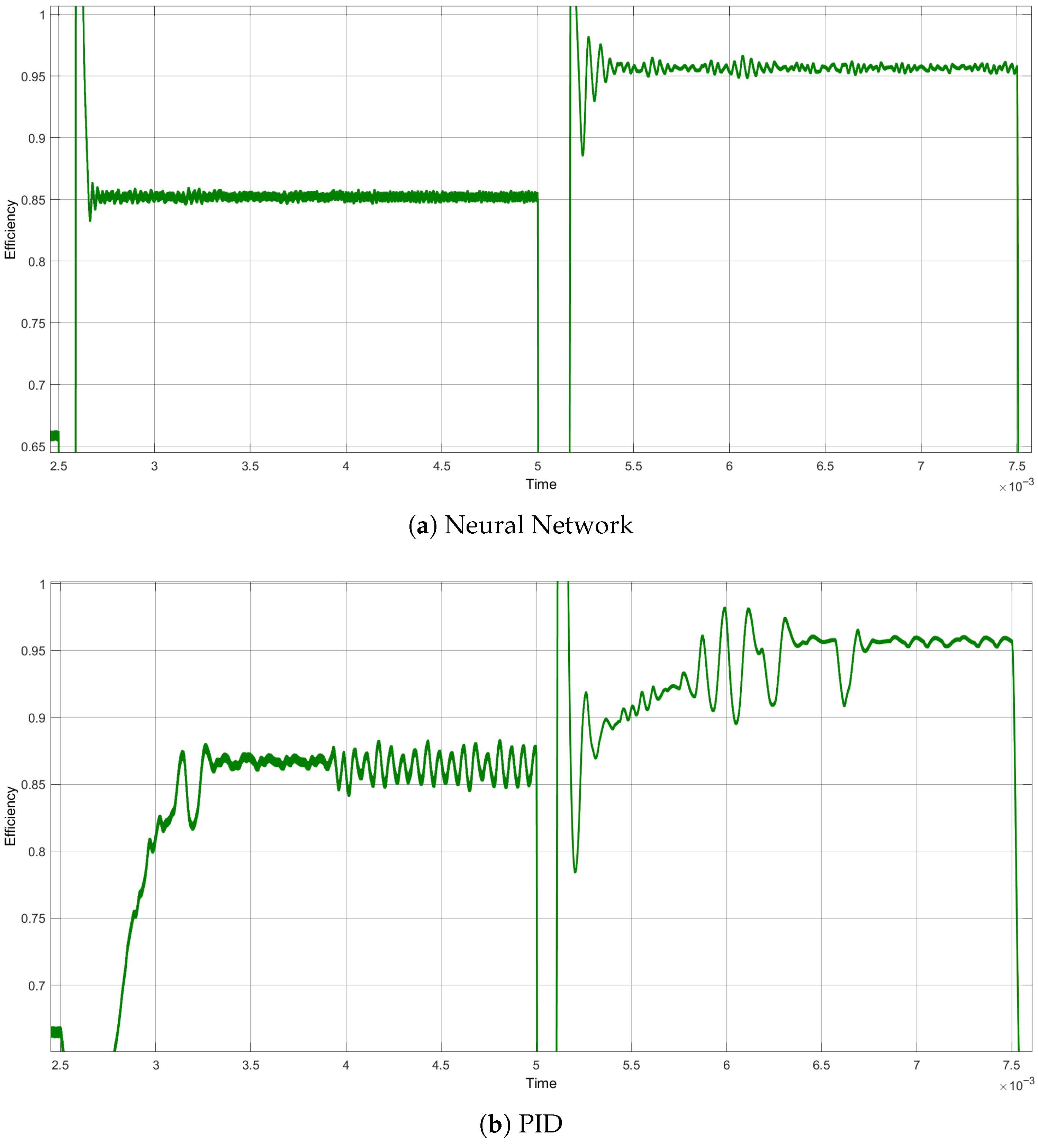
The converter was then simulated and the estimated efficiencies are shown in Figure 24b for the PID control and Figure 24a for neuro-fuzzy approach. It can be observed that the proposed method achieves faster settling times and a less noisy steady-state response.
Figure 24.
Efficiency analysis of the converter with (a) Neural Network control and (b) PID control.
5.4.2. Resource Utilization
The high-fidelity switching model of the converter was implemented with the Simscape Libraries in Matlab/Simulink on an MSI laptop equiped with an Intel(R) Core(TM) i7-7700HQ CPU @ 2.80 GHz, 8 GB of RAM, and NVIDIA GeForce GTX 1050 Ti (4 GB) graphics card. Fuzzy logic and Neural Network controllers were also developed using Matlab/Simulink functionalities. VHDL code was generated using the Vivado 2022.1 synthesis tool, and deployed on a Xilinx XC7Z020-1CLG848C Zynq-7000 AP SoC FPGA. Table 6 summarizes the FPGA’s resource utilization after embedding the two neural networks. The total on-chip power consumption was 0.605 W, with a junction temperature of 32 °C, indicating low thermal impact at the control level. The use of Wide Bandgap (SiC) devices enabled high-frequency operation with reduced switching losses, improving efficiency and power density.
Table 6.
Summary of FPGA resource utilization.
6. Conclusions
This work presented a novel neuro-fuzzy approach for controlling a DC-DC converter. A bidirectional converter was designed with a 400 VDC input, a wide output voltage range of 200–800 VDC, and a high switching frequency of 500 kHz, characteristics fully corresponding to electric vehicle applications. The PID control design procedure was first examined, showing that boost mode operation can lead to instability. A fuzzy logic controller was then developed, validated, and implemented, demonstrating superior performance over PID while maintaining a simple design process. Extensive closed-loop simulation data obtained with the fuzzy controller were used to train Neural Networks for both buck and boost operating modes. Each network employed a two-input, single-output architecture with one hidden layer. The fuzzy control strategy was successfully transferred to the neural networks, and VHDL code was generated for hardware validation. The proposed method for controlling the nonlinear DC-DC converter in both operating modes was verified using an FPGA-in-the-loop approach. Compared with the benchmark control methodology, the results showed a 33.7% reduction in RMSE along with a faster transient response. From an engineering perspective, the proposed design balances performance, efficiency, and implementation complexity, making it suitable for real-time embedded applications.
While the proposed approach demonstrates promising performance and efficient FPGA implementation, some limitations should be noted. The validation has been primarily conducted through simulation and FIL; therefore, further experimental verification using a physical converter is required. In addition, a more comprehensive assessment under varying load conditions and parameter uncertainties is necessary to fully evaluate robustness. Furthermore, formal nonlinear stability proofs, sensitivity analysis, evaluation of efficiency, power losses, and thermal performance, is required and will be addressed in the next stage of this work. Finally, the extension of the proposed methodology to other converter topologies and operating conditions remains an open area for future investigation.
Author Contributions
Conceptualization, E.M.-V. and P.B.-S.; methodology, E.M.-V.; software, P.B.-S. and A.R.-M.; validation, P.B.-S., A.R.-M. and J.M.R.-C.; formal analysis, E.M.-V.; investigation, E.M.-V.; resources, P.B.-S., A.R.-M., J.M.R.-C. and P.G.-G.; data curation, E.M.-V.; writing—original draft preparation, E.M.-V.; writing—review and editing, P.B.-S., A.R.-M., J.M.R.-C. and P.G.-G.; visualization, E.M.-V.; supervision, P.B.-S., A.R.-M. and J.M.R.-C.; project administration, J.M.R.-C. and P.G.-G.; funding acquisition, J.M.R.-C. and P.G.-G. All authors have read and agreed to the published version of the manuscript.
Funding
This research was funded by Universidad de las Américas-Puebla (UDLAP) and the Secretaría de Humanidades, Ciencia, Tecnología e Innovación (SECIHTI).
Data Availability Statement
The raw data supporting the conclusions of this article will be made available by the authors on request.
Acknowledgments
The authors would like to thank Universitat de València-Spain, Universidad de las Américas-Puebla (UDLAP), Instituto Nacional de Astrofísica, Óptica y Electrónica (INAOE) and SECIHTI-México for their support to develop this project.
Conflicts of Interest
The authors declare no conflicts of interest.
References
- Lee, H.J.; Liu, Y.; Chatfield, R.B. Neighborhood-scale ambient NO2 concentrations using TROPOMI NO2 data: Applications for spatially comprehensive exposure assessment. Sci. Total Environ. 2023, 857, 159342. [Google Scholar] [CrossRef] [Scilit]
- Xue, R.; Wang, S.; Zhang, S.; He, S.; Liu, J.; Tanvir, A.; Zhou, B. Estimating city NOX emissions from TROPOMI high spatial resolution observations—A case study on Yangtze River Delta, China. Urban Clim. 2022, 43, 101150. [Google Scholar] [CrossRef] [Scilit]
- Yang, A.; Tan, Q.; Rajapakshe, C.; Chin, M.; Yu, H. Global premature mortality by dust and pollution PM2.5 estimated from aerosol reanalysis of the modern-era retrospective analysis for research and applications, version 2. Front. Environ. Sci. 2022, 10. [Google Scholar] [CrossRef] [Scilit]
- Greene, C.A.; Gardner, A.S.; Wood, M.; Cuzzone, J.K. Ubiquitous acceleration in Greenland Ice Sheet calving from 1985 to 2022. Nature 2024, 625, 523–528. [Google Scholar] [CrossRef] [Scilit]
- United Nations. How Is Climate Change Impacting the World’s Ocean; United Nations: New York, NY, USA, 2024. [Google Scholar]
- United Nations. THE 17 GOALS|Sustainable Development; United Nations: New York, NY, USA, 2025. [Google Scholar]
- Leach, F.; Kalghatgi, G.; Stone, R.; Miles, P. The scope for improving the efficiency and environmental impact of internal combustion engines. Transp. Eng. 2020, 1, 100005. [Google Scholar] [CrossRef] [Scilit]
- Martinez-Vera, E.; Banuelos-Sanchez, P. Review of Bidirectional DC-DC Converters and Trends in Control Techniques for Applications in Electric Vehicles. IEEE Lat. Am. Trans. 2024, 22, 144–155. [Google Scholar] [CrossRef] [Scilit]
- Wang, D.; Shen, Z.J.; Yin, X.; Tang, S.; Liu, X.; Zhang, C.; Wang, J.; Rodriguez, J.; Norambuena, M. Model Predictive Control Using Artificial Neural Network for Power Converters. IEEE Trans. Ind. Electron. 2022, 69, 3689–3699. [Google Scholar] [CrossRef] [Scilit]
- Parvez, M.; Pereira, A.T.; Ertugrul, N.; Weste, N.H.E.; Abbott, D.; Al-Sarawi, S.F. Wide Bandgap DC–DC Converter Topologies for Power Applications. Proc. IEEE 2021, 109, 1253–1275. [Google Scholar] [CrossRef] [Scilit]
- Martínez-Vera, E.; Bañuelos-Sanchez, P.; Etcheverry, G. Comparative Examination of Control Strategies in DC-DC Power Converters: A Traditional and Artificial Intelligence Perspective. J. Intell. Syst. Control 2023, 2, 82–98. [Google Scholar] [CrossRef] [Scilit]
- Ogata, K. Modern Control Engineering; Prentice Hall: Upper Saddle River, NJ, USA, 2010. [Google Scholar]
- Khleaf, H.K.; Nahar, A.K.; Jabbar, A.S. Intelligent control of DC-DC converter based on PID-neural network. Int. J. Power Electron. Drive Syst. (IJPEDS) 2019, 10, 2254–2262. [Google Scholar] [CrossRef] [Scilit]
- Chen, C.L. Many-Objective Adaptive Fuzzy With Sliding Mode Control for a Class of Switching Power Converters Using Global Optimization. IEEE Access 2022, 10, 10317–10332. [Google Scholar] [CrossRef] [Scilit]
- Wang, L.; Chai, S.; Yoo, D.; Gan, L.; Ng, K. PID and Predictive Control of Electrical Drives and Power Converters Using MATLAB®/SIMULINK®; John Wiley & Sons Singapore Pte. Ltd.: Singapore, 2015. [Google Scholar]
- Malge, S.V.; Ghogare, M.G.; Patil, S.L.; Deshpande, A.S.; Pandey, S.K. Chatter-Free Non-Singular Fast Terminal Sliding Mode Control of Interleaved Boost Converter. IEEE Trans. Circuits Syst. II Express Briefs 2023, 70, 186–190. [Google Scholar] [CrossRef] [Scilit]
- Nasim, U.; Bhatti, A.R.; Farhan, M.; Rasool, A.; Butt, A.D. Finite-time robust speed control of synchronous reluctance motor using disturbance rejection sliding mode control with advanced reaching law. PLoS ONE 2023, 18, e0291042. [Google Scholar] [CrossRef] [Scilit]
- Nasim, U.; Bhatti, A.R.; Farhan, M.; Zeb, O.; Butt, A.D.; Paracha, K.N. An improved barrier function double integral sliding mode control of SynRM for hybrid energy storage system-based electric vehicle. J. Energy Storage 2024, 104, 114401. [Google Scholar] [CrossRef] [Scilit]
- Choi, B. Pulsewidth Modulated DC-to-DC Power Conversion; John Wiley & Sons, Inc.: Hoboken, NJ, USA, 2013. [Google Scholar] [CrossRef] [Scilit]
- Chen, J.; Chen, Y.; Tong, L.; Peng, L.; Kang, Y. A Backpropagation Neural Network-Based Explicit Model Predictive Control for DC-DC Converters with High Switching Frequency. IEEE J. Emerg. Sel. Top. Power Electron. 2020, 8, 2124–2142. [Google Scholar] [CrossRef] [Scilit]
- Khan, H.S.; Mohamed, I.S.; Kauhaniemi, K.; Liu, L. Artificial Neural Network-Based Voltage Control of DC/DC Converter for DC Microgrid Applications. In Proceedings of the 2021 6th IEEE Workshop on the Electronic Grid (eGRID), New Orleans, LA, USA, 8–10 November 2021; pp. 1–6. [Google Scholar] [CrossRef] [Scilit]
- Yarikkaya, S.; Vardar, K. Neural Network Based Predictive Current Controllers for Three Phase Inverter. IEEE Access 2023, 11, 27155–27167. [Google Scholar] [CrossRef] [Scilit]
- Bakeer, A.; Mohamed, I.S.; Malidarreh, P.B.; Hattabi, I.; Liu, L. An Artificial Neural Network-Based Model Predictive Control for Three-Phase Flying Capacitor Multilevel Inverter. IEEE Access 2022, 10, 70305–70316. [Google Scholar] [CrossRef] [Scilit]
- Dong, W.; Li, S.; Fu, X.; Li, Z.; Fairbank, M.; Gao, Y. Control of a Buck DC/DC Converter Using Approximate Dynamic Programming and Artificial Neural Networks. IEEE Trans. Circuits Syst. I Regul. Pap. 2021, 68, 1760–1768. [Google Scholar] [CrossRef] [Scilit]
- Li, S.; Fairbank, M.; Johnson, C.; Wunsch, D.C.; Alonso, E.; Proao, J.L. Artificial neural networks for control of a grid-Connected rectifier/inverter under disturbance, dynamic and power converter switching conditions. IEEE Trans. Neural Netw. Learn. Syst. 2014, 25, 738–750. [Google Scholar] [CrossRef] [Scilit]
- Heydari, A. Optimal Switching of DC-DC Power Converters Using Approximate Dynamic Programming. IEEE Trans. Neural Netw. Learn. Syst. 2018, 29, 586–596. [Google Scholar] [CrossRef] [Scilit]
- Wang, Y.; Wang, Y.; Song, X.; Liang, Z. Finite-Time Adaptive Neural Network Observer-Based Output Voltage-Tracking Control for DC–DC Boost Converters. IEEE Trans. Circuits Syst. I Regul. Pap. 2023, 70, 3005–3016. [Google Scholar] [CrossRef] [Scilit]
- Gangula, S.D.; Nizami, T.K.; Udumula, R.R.; Chakravarty, A.; Singh, P. Adaptive neural network control of DC-DC power converter. Expert Syst. Appl. 2023, 229, 120362. [Google Scholar] [CrossRef] [Scilit]
- Rubaai, A.; Ofoli, A.; Burge, L.; Garuba, M. Hardware implementation of an adaptive network-based fuzzy controller for DC-DC converters. IEEE Trans. Ind. Appl. 2005, 41, 1557–1565. [Google Scholar] [CrossRef] [Scilit]
- Wu, Y.E.; Huang, W.C. Dual-Input Interleaved Bidirectional DC-DC Converter for Light Electric Vehicles. IEEE J. Emerg. Sel. Top. Power Electron. 2023, 11, 5037–5051. [Google Scholar] [CrossRef] [Scilit]
- Ragasudha, C.P.; Hemamalini, S. Performance Analysis of a High Gain Bidirectional DC-DC Converter Fed Drive for an Electric Vehicle with Battery Charging Capability During Braking. IEEE Access 2024, 12, 14499–14511. [Google Scholar] [CrossRef] [Scilit]
- Sojoudi, T.; Sarhangzadeh, M.; Olamaei, J.; Ardashir, J.F. An Extendable Bidirectional High-Gain DC-DC Converter for Electric Vehicle Applications Equipped with IOFL Controller. IEEE Trans. Power Electron. 2023, 38, 9767–9779. [Google Scholar] [CrossRef] [Scilit]
- Aeggegn, D.B.; Nyakoe, G.N.; Wekesa, C. ANFIS-Controlled Boost and Bidirectional Buck-Boost DC-DC Converters for Solar PV, Fuel Cell, and BESS-Based Microgrid Application. Int. Trans. Electr. Energy Syst. 2024, 2024, 6484369. [Google Scholar] [CrossRef] [Scilit]
- Seesamlee, P.; Pakdeeto, J.; Suyapan, A.; Areerak, K. Optimal Controller Design for Bidirectional DC–DC Converter in Battery Electric Vehicle System Using the Adaptive Tabu Search Algorithm. IEEE Access 2026, 14, 27381–27393. [Google Scholar] [CrossRef] [Scilit]
- Dwivedi, Y.K.; Jeyaraj, A.; Hughes, L.; Davies, G.H.; Ahuja, M.; Albashrawi, M.A.; Al-Busaidi, A.S.; Al-Sharhan, S.; Al-Sulaiti, K.I.; Altinay, L.; et al. “Real impact”: Challenges and opportunities in bridging the gap between research and practice—Making a difference in industry, policy, and society. Int. J. Inf. Manag. 2024, 78, 102750. [Google Scholar] [CrossRef] [Scilit]
- Martinez-Vera, E. Algoritmos de Aprendizaje de Máquina Validados Mediante Metodologías Hardware-in-the-Loop con Aplicaciones en el Sistema de Propulsión de Vehículos Eléctricos. Ph.D. Thesis, Universidad de las Américas-Puebla (UDLAP), Puebla, Mexico, 2025. [Google Scholar]
- Liu, J.; Wei, T.; Chen, N.; Liu, W.; Wu, J.; Xiao, P. Data-Mining-Based Hardware-Efficient Neural Network Controller for DC–DC Switching Converters. IEEE J. Emerg. Sel. Top. Power Electron. 2023, 11, 4222–4232. [Google Scholar] [CrossRef] [Scilit]
- Liao, Y.; Li, Y.; Chen, M.; Nordstrom, L.; Wang, X.; Mittal, P.; Poor, H.V. Neural Network Design for Impedance Modeling of Power Electronic Systems Based on Latent Features. IEEE Trans. Neural Netw. Learn. Syst. 2023, 35, 5968–5980. [Google Scholar] [CrossRef] [Scilit]
- Chakraborty, S.; Mazuela, M.; Tran, D.D.; Corea-Araujo, J.A.; Lan, Y.; Loiti, A.A.; Garmier, P.; Aizpuru, I.; Hegazy, O. Scalable Modeling Approach and Robust Hardware-in-the-Loop Testing of an Optimized Interleaved Bidirectional HV DC/DC Converter for Electric Vehicle Drivetrains. IEEE Access 2020, 8, 115515–115536. [Google Scholar] [CrossRef] [Scilit]
- Tong, Y.; Salhi, I.; Wang, Q.; Lu, G.; Wu, S. Bidirectional DC-DC converter topologies for hybrid energy storage systems in electric vehicles: A comprehensive review. Energies 2025, 18, 2312. [Google Scholar] [CrossRef] [Scilit]
- Wang, J.; Wang, B.; Zhang, L.; Wang, J.; Shchurov, N.; Malozyomov, B. Review of bidirectional DC–DC converter topologies for hybrid energy storage system of new energy vehicles. Green Energy Intell. Transp. 2022, 1, 100010. [Google Scholar] [CrossRef] [Scilit]
- Kazimierczuk, M.K. Pulse-Width Modulated DC-DC Power Converters; John Wiley & Sons: Hoboken, NJ, USA, 2015. [Google Scholar]
- SAE J1772; SAE Electric Vehicle and Plug in Hybrid Electric Vehicle Conductive Charge Coupler. SAE International: Warrendale, PA, USA, 2017.
- Huang, X.; Lee, F.C.; Li, Q.; Du, W. High-Frequency High-Efficiency GaN-Based Interleaved CRM Bidirectional Buck/Boost Converter with Inverse Coupled Inductor. IEEE Trans. Power Electron. 2016, 31, 4343–4352. [Google Scholar] [CrossRef] [Scilit]
- Martínez-Vera, E.; Bañuelos-Sánchez, P.; Rosado-Muñoz, A. Design and Validation of a Bidirectional DC-DC Converter Control for Electric Vehicles Using FPGA-in-the-Loop Methodology. J. Eur. Des Systèmes Autom. 2024, 57, 77–85. [Google Scholar] [CrossRef] [Scilit]
- Michal, V. Optimal Load Transient Response of the Boost DC-DC Converter Based on Stochastic Duty-cycle Sequence Generator. In Proceedings of the 2021 31st International Conference Radioelektronika, RADIOELEKTRONIKA 2021, Brno, Czech Republic, 19–21 April 2021. [Google Scholar] [CrossRef] [Scilit]
- Rashid, M.H. Power Electronics Handbook, 4th ed.; Elsevier: Amsterdam, The Netherlands, 2018. [Google Scholar]
- Nguyen, A.T.; Taniguchi, T.; Eciolaza, L.; Campos, V.; Palhares, R.; Sugeno, M. Fuzzy control systems: Past, present and future. IEEE Comput. Intell. Mag. 2019, 14, 56–68. [Google Scholar] [CrossRef] [Scilit]
- Chelladurai, B.; Sundarabalan, C.K.; Santhanam, S.N.; Guerrero, J.M. Interval Type-2 Fuzzy Logic Controlled Shunt Converter Coupled Novel High-Quality Charging Scheme for Electric Vehicles. IEEE Trans. Ind. Inform. 2021, 17, 6084–6093. [Google Scholar] [CrossRef] [Scilit]
- Trillo, J.R.; Del Moral, M.J.; Tapia, J.M.; García-Cabello, J.; Cabrerizo, F.J. Explainable classifier with adaptive optimisation for medical data. Appl. Intell. 2026, 56, 77. [Google Scholar] [CrossRef] [Scilit]
- Castillo, O. Type-2 Fuzzy Logic in Intelligent Control Applications; Studies in Fuzziness and Soft Computing; Springer: Berlin/Heidelberg, Germany, 2012; Volume 272. [Google Scholar] [CrossRef] [Scilit]
- Bennaoui, A.; Saadi, S.; Ameur, A. Invasive weed optimization algorithm for tuning transitioning from type-1 to interval type-2 fuzzy logic controller for boost DC-DC converters. J. Eur. Des Syst. Autom. 2020, 53, 195–202. [Google Scholar] [CrossRef] [Scilit]
- Feng, G. A survey on analysis and design of model-based fuzzy control systems. IEEE Trans. Fuzzy Syst. 2006, 14, 676–697. [Google Scholar] [CrossRef] [Scilit]
- Passino, K.M.; Yurkovich, S. Fuzzy Control; Addison-Wesley: Reading, MA, USA, 1998; p. 475. [Google Scholar]
- Nocedal, J.; Wright, S.J. Numerical Optimization; Springer: New York, NY, USA, 2006. [Google Scholar] [CrossRef] [Scilit]

Disclaimer/Publisher’s Note: The statements, opinions and data contained in all publications are solely those of the individual author(s) and contributor(s) and not of MDPI and/or the editor(s). MDPI and/or the editor(s) disclaim responsibility for any injury to people or property resulting from any ideas, methods, instructions or products referred to in the content. |
© 2026 by the authors. Licensee MDPI, Basel, Switzerland. This article is an open access article distributed under the terms and conditions of the Creative Commons Attribution (CC BY) license.