


Abstract
This paper comprehensively reviews friction stir welding (FSW) as applied to copper and its alloys. FSW is a solid-state joining process that offers significant advantages over traditional fusion welding methods, particularly for materials like copper that are difficult to weld conventionally due to their high thermal conductivity and oxidation issues. Over time, the FSW process has been developed for different industries. Copper structures joined through FSW are utilized for nuclear waste storage, electrical connectors, chemical and petrochemical storage, refrigeration systems, heat exchangers, and the aerospace industry. This covers recent advancements in FSW technology, the geometry of the tools used, the process parameters, and the microstructural characteristics and mechanical properties of the joints. It examines the shapes, sizes, and materials of the tools used for welding copper and its alloys, along with process parameters such as rotational speed and traverse speed, and their influence on the quality of the joints. Additionally, the paper presents syntheses of previously published results, highlighting the values of parameters that indicate the quality of the welds, including grain size, microhardness, mechanical strength, and elongation. The challenges and potential solutions in applying FSW to copper are also discussed, providing a starting point for future research and industrial applications.
1. Introduction
Copper and its alloys are widely used in industry as they have advantageous properties such as high thermal and electrical conductivity, good mechanical and corrosion resistance, good ductility, etc. [1,2]. Due to its high thermal conductivity and high oxidation rate, copper is difficult to weld by conventional welding processes [3]; over the last 15 years, a great deal of research has been carried out on joining copper and its alloys by friction stir welding (FSW).
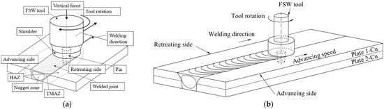
Friction stir welding is a solid-state welding process developed and patented by W.M. Thomas et al. at The Welding Institute (TWI, UK) in 1991 [4]. According to the literature [3,5,6,7,8,9,10,11], FSW has the following advantages: FSW-welded structures have reduced distortion and shrinkage; FSW joints have superior mechanical properties and a fine microstructure; no filler material is needed; there is no need for gasses or shielding materials; the process has low energy consumption; there is no molten material, so no spatter or other gasses are formed; there is no loss of alloying elements; no UV radiation; and no post-weld mechanical processing required. There are several FSW process schemes, which differ in the positioning of the plates, the input parameters used, the technological role of the parts in the ex-welding, etc. The most widely used FSW process schemes are shown in Figure 1. Figure 1a represents a butt positioning of the plates, where the joint is realized between the common side surfaces, and Figure 1b shows the stacked positioning of the plates, where the joint is realized between the lower surface of the upper plate and the upper surface of the lower plate.
Figure 1.
Schematic of the FSW process: (a) butt joint [12]; (b) lap joint.
FSW is a solid-state joining method in which a special rotating tool, consisting of a shoulder and a pin, moves along the contact surfaces of plates rigidly fixed to a backing plate. The shoulder presses against the upper surfaces of the plates and the pin mixes the volume of material. As the tool moves along the welding direction, the material of the plates undergoes severe plastic deformation and is transported from the front of the tool to the back.
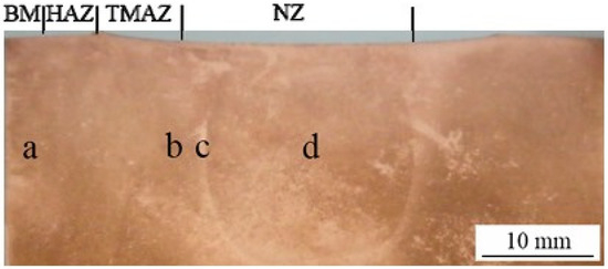
The friction between the shoulder of the tool and the top surface of the plates, respectively, and the friction between the tool pin and the splice materials produce heat and severe plastic deformation leading to the material being brought into a visco-plastic state and the weld bead forming. As can be seen in Figure 2, the weld bead produced by FSW is divided into four distinct zones: the nugget zone (NZ), the thermo-mechanically affected zone (TMAZ), the heat-affected zone (HAZ), and the base material (BM), the unaffected zone [13].
Figure 2.
Microstructural regions of the FSW process for pure Cu 1/2H [14]. (a) base metal (BM); (b) heat affected zone (HAZ); (c) thermo-mechanically-affected zone (TMAZ); (d) nugget zone (NZ).
Over the years, the FSW process has been developed according to several principles and efficiency strategies for different fields of use. In terms of the exploitation of FSW-joined copper structures, these are found in various fields: tanks and canisters for nuclear waste [13,15,16,17], electrical connectors [18,19,20], chemical and petrochemical fuel tanks [17,21,22], heat exchangers [18], the aerospace industry [21,23,24], and refrigeration installations [19,25,26].
This paper analyzes the results obtained by the friction stir welding of copper and its alloys in terms of microstructure, mechanical properties, and the temperatures obtained, as published in the literature. The shapes, sizes, and materials of the tools used for welding copper and its alloys, as well as the technological parameters (rotational speed and traverse speed) and their influence on the quality of the weld, were analyzed. Also presented are summaries based on the results published so far on the values of the parameters denoting the quality of the joints obtained (grain size, microhardness, mechanical strength, elongation).
To fully understand the effects of the main process parameters, such as rotational speed, traverse speed, penetration force, as well as the shape, dimensions, and tilt angle of the tool on the microstructure and mechanical properties of the welded joints, it is necessary to analyze the joints obtained under different conditions. The most important factors that appear during the welding process are the heat generated by the friction between the FSW tool and the weld plates and the plastic deformation of the weld material.
This paper gives an overview of the current state of research in the field of FSW of copper and its alloys, focusing on the positive and negative aspects of this process. A synthesis of information from previous studies is presented, which is particularly useful to researchers in the field, as it provides recommendations for the improvement of technological parameters and tool geometry in order to obtain defect-free joints with superior mechanical properties suitable for various industrial applications. The syntheses presented and the conclusions drawn can form the basis for future fundamental and applied research in an efficient and well-documented manner.
2. Tool Geometry
The tool used in the FSW process realizes rotational and traverse motion and heats the materials to the optimum temperature, plastically deforms the base materials, and mixes them to produce a high-quality bead. The geometry and dimensions of the FSW tool have an important impact on the quality of the resulting joints. The tool must have a specific geometry to provide an even temperature distribution and proper material flow. The correct choice of tool geometry can lead to flawless packings with superior mechanical properties and a uniform microstructure.
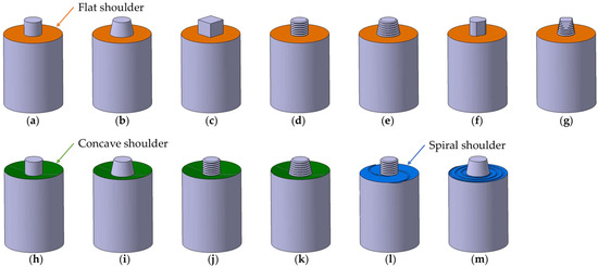
The construction of the tool comprises a shoulder, which retains the mixed material and provides thermal input by friction with the upper surfaces of the mixing plates, and a pin which penetrates the plates and generates heat by local plastic deformation and mixes the material. The shoulder can have various shapes such as: flat [6,8,14,15,21,27,28,29,30,31,32,33,34,35,36,37,38,39,40,41,42,43,44,45,46,47,48], concave [1,13,16,29,49,50,51,52,53,54], spiral [29,55].
When welding pure copper, the flat shoulder, concave shoulder, and spiral shoulder have different behaviors in terms of heat generation and material mixing. The flat shoulder is simple, easy to achieve, but can generate more heat in a certain area, which can lead to overheating of the material and a higher risk of defect formation. In contrast, the concave shoulder leads to a more even heat distribution and has frequently been used when welding 3 mm thick plates. Thus, when welding 3 mm thick Cu plates at low rotational speeds and traverse speeds of the order of 50 mm/min–100 mm/min, higher quality welds with improved mechanical properties and finer microstructure are obtained [49,50,51,56]. The spiral shoulder enables more precise temperature control during welding. By distributing the heat evenly, this shape helps maintain a constant temperature in the weld zone, preventing overheating and degradation of the microstructure of the material [51]. However, when using technological parameters that lead to excessive heating (800 °C at low rotational and traverse speeds), the inferior mechanical properties of the base material are obtained [55].
In the literature, the pin is found in different forms, the main ones being: a cylindrical pin [1,7,13,30,34,35,38,39,40,44,45,46,47,57,58,59], a cylindrical threaded pin [3,6,14,15,16,21,29,31,32,36,37,38,41,42,48,50,51,52,53], a conical pin [8,27,28,43,55,56,60,61,62,63,64], a conical threaded pin [28,33,49,54,65], and a square pin [32,34]. Figure 3 represents the tool shapes of FSW (shoulder and pin) tools used for copper butt joints based on the literature [1,3,6,7,8,13,14,15,16,21,27,28,29,30,31,32,33,34,35,36,37,38,39,40,41,42,43,44,45,49,50,51,52,53,54,55,56,57,64,65,66,67].
Figure 3.
FSW tool shapes used for copper butt joints: (a) flat shoulder (orange) and cylindrical pin; (b) flat shoulder and conical pin; (c) flat shoulder and square pin; (d) flat shoulder and cylindrical threaded pin; (e) flat shoulder and conical threaded pin; (f) flat shoulder and cylinder with three-plane pin; (g) flat shoulder and threaded cylindrical pin with four planes; (h) concave (green) shoulder and cylindrical pin; (i) concave shoulder and conical pin; (j) concave shoulder and threaded cylindrical pin; (k) concave shoulder and conical threaded pin; (l) spiral shoulder (blue) and threaded cylindrical pin; (m) spiral shoulder and conical pin.
The cylindrical pin is commonly used because it facilitates uniform heat distribution, has a simple shape, and is easy to obtain, but it can lead to voids and pores when joining thick sheets due to low material flow. The threaded cylindrical pin reduces the risk of voids and pores, providing a higher quality weld, but can generate additional heat, requiring careful control of welding parameters to prevent the overheating of the material. The conical pin facilitates penetration and is often used for thicker materials or copper alloys. In the case of threaded conical pins, the threading improves material mixing around the pin. The square shape of the pin helps to create shear forces, which improves material mixing and reduces the risk of flaw formation but can lead to faster pin wear due to large contact surfaces and high forces.
The flat shoulder of the tool is generally between Ø12 mm and Ø24 mm in diameter, the associated pin being cylindrical (Ø3–Ø8 mm), with a cylindrical thread (M3–M8), and a conical or square cross-section depending on the thickness and type of material used. The concave shoulder has diameters ranging from Ø12 mm to Ø20 mm and is generally conical, threaded conical, or threaded cylindrical pin.
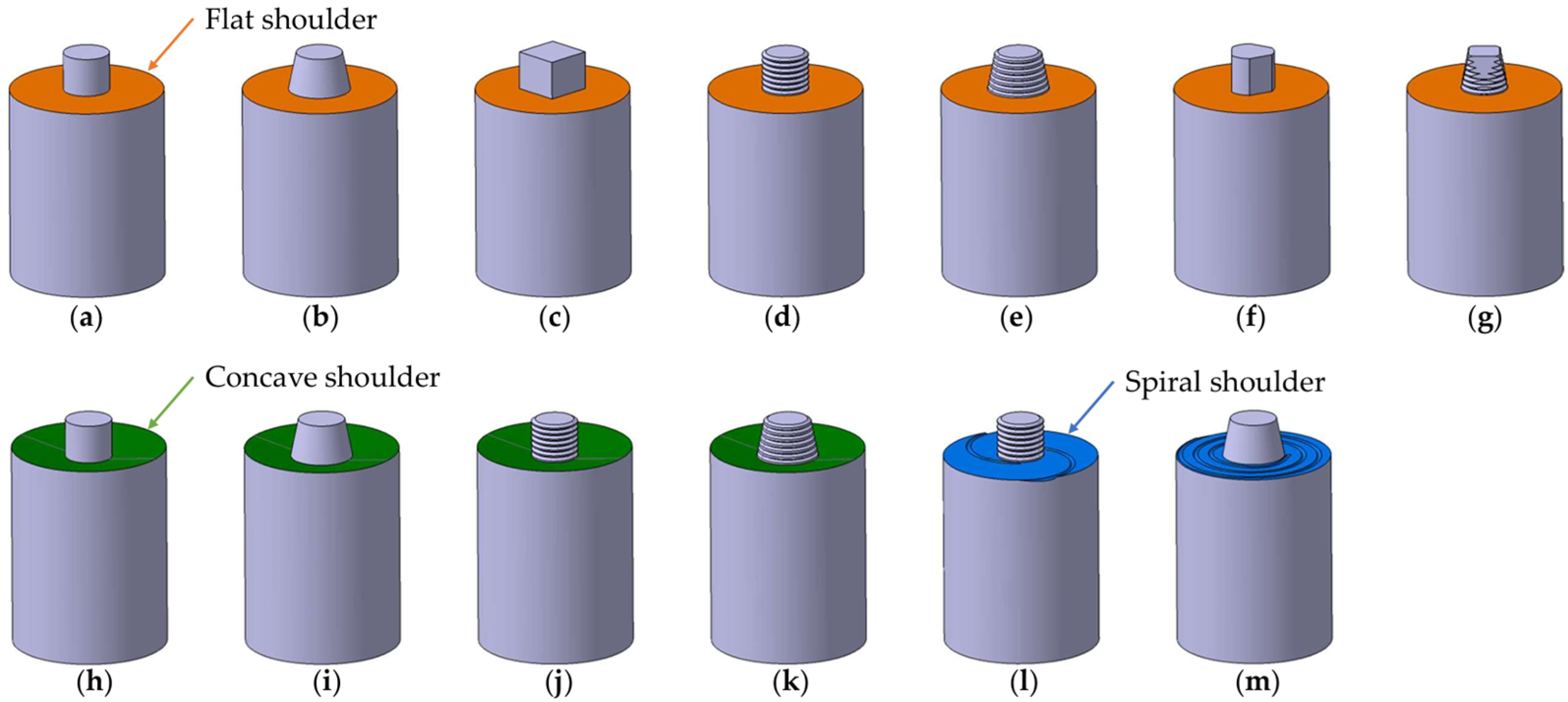
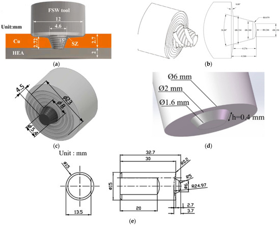
Figure 4 shows graphical representations of the FSW tools used for joining copper or copper alloys with different plate thicknesses. Specifically, Figure 4a shows a tool with a flat shoulder and threaded conical pin used for lap welding between Cu T3 and a multicomponent HEA alloy. Figure 4b illustrates a tool with a spiral shoulder and a spiral conical pin featuring helical grooves, which join the copper rotor’s end rings. Figure 4c represents a tool with a flat shoulder and a threaded conical pin used for butt-joining Cu-ETP R220 plates with a thickness of 5 mm.
Figure 4.
Schematic representations of FSW tools: (a) threaded conical pin [68]; (b) spiral conical pin featuring helical grooves [69]; (c) threaded conical pin [55]; (d) conical pin [70]; and (e) conical pin [71].
Figure 4d is a tool with a flat shoulder and conical pin used for joining ultra-thin sheets of Cu T2 and H62 brass with a thickness of 0.6 mm. Figure 4e represents a tool with a concave shoulder and conical pin used for welding Beryllium-Copper alloy C17200 with a plate thickness of 3 mm.
Xue et al. [15] used a Ø20 mm flat shoulder tool with a 4.7 mm long M6 threaded cylindrical pin and obtained defect-free joints when welding two pure copper plates butt at low heat input, i.e., for rotational speeds of 400–800 rpm and traverse speed of 50–200 mm/min. Using the same tool geometry, Xie et al. [31] achieved good quality joints with reduced heat input.
Wang et al. [67] used a tool with a concave shoulder and threaded conical pin when welding a harder copper alloy where he obtained defect-free joints and sufficient material flow even though the heat input was not the greatest.
Khodaverdizadeh et al. [32] compared the results obtained when using a square pin and a threaded cylindrical pin, the other tool characteristics being identical, in which it was found that using the square pin resulted in much higher quality and stronger structures compared to the threaded cylindrical pin. Also, Galvão et al. [29] affirms that for tools with a flat shoulder, the FSW tool’s torque is much lower than that of a concave or spiral shoulder, but provides much poorer material flow, resulting in flawed structures, whereas the spiral shoulder provides adequate material flow and higher grain refinement. The spiral-shouldered tool generated the most heat and favored optimal material flow, resulting in higher quality joints.
The most frequently used FSW tooling materials for butt welding of copper structures are high-speed steels H13 [3,30,34,35,36,37,39,43,53]. Tungsten carbide tools were used for the thicker plate WC [33], and for high-hardness copper alloys, alloys based on Ni [49], Inconel 718 [65], TiC-based cermet [67], X210Cr12 [64], X32CrMo3 3 [42], X32CrMoV12-28 [6], and SKD61 [72].
H13 high-speed steels are low-cost and have good hardness but wear quickly when welding copper due to the high thermal conductivity of copper. Metallic carbides have good wear resistance and thermal stability and can be used at high temperatures without degradation, but are brittle and expensive. Nickel-based alloys have good thermal stability, oxidation resistance, and maintain their mechanical properties at high temperatures, but are expensive and difficult to machine. Composite materials have very good hardness and wear resistance and superior mechanical and thermal stability, but are complex and costly to manufacture.
3. Process Parameters of FSW
The most important parameters of the FSW are the rotational speed of the tool, which can be clockwise or counterclockwise, and the traverse speed, which can be either the tool or workpiece traverse speed. The quality of the joints is influenced by the combination of rotational speed and traverse speed. The best combination should ensure good mixing of the material, prevention of defects, and superior mechanical properties. According to the literature, the range of tool speed values varies from 200 to 2050 rpm and the traverse speed is in the range of 16–900 mm/min, which denotes a fairly high flexibility in adapting the FSW process to different copper alloys and operating conditions.
The most used values of the technological parameters of the FSW process are a rotational speed of 600 rpm [3,7,15,21,28,31,32,34,36,38,39,46,49,50,51,67] and a traverse speed of 50 mm/min [3,7,15,31,35,39,49,51,52,67]. The tilt angle of the tool has generally been in the range of 1–3°, but most investigations have been carried out without tilting the tool [3,6,8,19,28,30,31,32,35,36,39,40,42,43,47,48,49,50,51,53,55,57,58,63,65,66,73]. The most used tool angle was 2.5° [17,23,34,38,41,44,52,54,72].
Sun et al. [7] studied the effects of rotational speed on the microstructure and mechanical properties of Cu T2 joints by keeping the traverse speed constant at 50 mm/min and varying the rotational speed for each experiment. They obtained the best results when using a rotational speed of 1000 rpm. At this rotational speed, a fine microstructure without defects and with superior mechanical properties was obtained. The same strategy has been addressed by Liu et al. [50], which for a traverse speed of 100 mm/min identified a rotational speed of 400 rpm as the best option for pure copper 1/2H joining. At rotational speeds above 600 rpm, larger grain sizes resulted in the bead zone due to the temperature rise and plastic deformation, while the grain size in the HAZ is not influenced by the increase in rotational speed.
The comparison of the parameters was also approached by keeping the rotational speed constant, where Shen et al. [51] found that most defects occurred at higher traverse speeds. It was observed that defects occurred at high traverse speeds (above 200 mm/min) and that the weld bead size decreased with increasing traverse speed. It has been established that the best traverse speed for FSW of pure copper in combination with a rotational speed of 600 rpm is about 50–100 mm/min, which achieves superior mechanical properties and a fine microstructure. Also, Barenji [34] achieves better properties than the base material by using a rotational speed of 600 rpm, and in cases where this is higher, the quality of the joint properties decreases significantly. The defects occurred at high traverse speeds and low rotational speeds. The tool used had a square pin and the heat input was empirically calculated as a function of the welding parameters, with the result that high rotational speeds and low traverse speeds increase the heat input.
The tool tilt angle aids in controlling material flow and generating frictional heat, facilitating material mixing and improving weld quality. Consequently, it helps reduce defects by ensuring a more uniform heat distribution in the welded area. However, the tilt angle requires precise tool control to prevent deviations and may contribute to uneven tool wear.
A tool tilt angle of 2.5° was used by Xue et al. [15] to weld 1/2H pure copper with a thickness of 5 mm, employing a flat-shouldered tool with a threaded cylindrical pin. They measured mechanical properties very close to those of the base material. The tool tilt contributed to material homogenization in the nugget zone (NZ), preventing void formation and enhancing the overall hardness of the welded area. The tool inclination facilitated the movement of the material from the advancing side to the retreating side, preventing the formation of voids or insufficiently mixed regions. Using similar parameters and the same tool design, Xie et al. [31] achieved mechanical properties comparable to those of the base material without tilting the tool. Defect-free joints were obtained, although the hardness achieved with similar welding parameters was lower.
A tilt angle of 2.5° used with different tool configurations shows an important influence on material flow and temperature distribution. For instance, the use of a concave shoulder Ø14 mm with a cylindrical threaded pin Ø4 mm at a tilt angle of 2.5° with rapid cooling significantly improved joint hardness and mechanical properties, particularly when welded at 400 rpm and 50 mm/min. The rapid cooling technique in conjunction with the tilt angle helped manage the excessive heat that could otherwise degrade joint quality [52].
The tilt angle can help in tailoring the FSW process to different material thicknesses and properties. For example, with a flat shoulder Ø20 mm and square pin 4.3 × 4.3 mm, a tilt angle of 2.5° at rotational speeds between 600 and 1200 rpm, and traverse speeds from 25 to 100 mm/min, resulted in different temperature profiles. This shows that the tilt angle, combined with specific rotational and traverse speeds, can be optimized to enhance joint quality [34].
A summary of published results on the FSW of copper is shown in Table 1, while results on the FSW of copper alloys are presented in Table 2. The two tables offer detailed information on FSW tooling, including the geometrical shape and material, as well as the process parameters used in the butt joining of plates. Each table focuses on different material categories and is organized by increasing plate thickness. In these tables, Vr represents the rotational speed, Va indicates the traverse speed, and Fa denotes the penetration force.
Table 1.
Particularities of tooling and FSW technological parameters of copper materials.
Table 2.
Particularities of tooling and FSW technological parameters of copper alloy materials.
The table presents variations in tooling, including shoulder type, pin geometry, materials used, and key process parameters like rotational speed, traverse speed, and applied force. These factors influence heat generation, material flow, and grain structure, directly impacting the mechanical properties and quality of the welded joint.
Table 2 focuses on copper alloys, which require different approaches than pure copper. Each entry provides details about the friction stir welding (FSW) tooling, including shoulder type, pin design, and the materials used for the tools, as well as specific process parameters tailored to the properties of copper alloys. Copper alloys, which may include elements like zinc, chromium, and zirconium, behave differently during the FSW process, often resulting in distinct microstructural and mechanical changes compared to pure copper. For example, the presence of these alloying elements can lead to grain refinement and increased hardness in the nugget zone (NZ). Additionally, adjusting rotational and traverse speeds can enhance control over these outcomes.
The following conclusions can be deduced from the summary presented in Table 1:
- Tools with a flat or concave shoulder and cylindrical or threaded cylindrical pin can be used successfully when welding Cu plates by generating the heat required for joining;
- Regardless of the shape and size of the tool and the values of the technological parameters in the heat-affected zone (HAZ), a microstructure with coarse grains and the poorest mechanical properties are obtained due to incomplete recrystallization;
- The nugget zone (NZ) is usually finer-grained than the heat-affected zone (HAZ) due to complete recrystallization, which leads to higher hardness and strength in the welded zone than in the HAZ;
- A temperature of 550 °C during friction stir welding (FSW) for pure copper is considered ideal for preventing defects and achieving good mechanical properties;
- The material thickness of the joined plates influences the choice of optimal process parameters.
Lower rotational speeds (400–600 rpm) combined with a medium traverse speed (50–100 mm/min) have been used for welding copper plates thicker than 3 mm; good results have been obtained when welding 3 mm thick plates with a rotational speed of 900 rpm and a traverse speed of 40 mm/min; for smaller thicknesses, higher traverse speeds are used to avoid the overheating of the material.
The following conclusions can be drawn from the summary presented in Table 2:
- Zinc content influences grain size in the joint area and joint hardness; a higher zinc content leads to smaller grains and increased hardness;
- The Cu-Cr-Zr alloy joints have improved microstructure and mechanical properties by using post-welding treatments such as rapid water cooling;
- For thin materials, higher rotational speeds (700–1000 rpm) and high traverse speeds are often more effective in ensuring homogeneous mixing and optimal temperature; for thicker materials, rotational speeds and traverse speeds should be reduced to allow optimal heating and prevent material damage;
- Defects such as porosities, cracks, and tunnels occurred when process parameters were incorrectly chosen.
The butt joining of copper and its alloys by the FSW process has become a topic of interest due to properties such as corrosion resistance, good thermal conductivity, and electrical conductivity.
In the FSW process, process parameters (tool rotation speed, traverse speed) control the amount of heat generated by friction and plastic deformation, which leads to a rise in temperature during the process. The temperature during friction stir welding influences the microstructure and mechanical properties of the weld as a consequence of the chosen process parameters.
Experimental research has focused on optimizing the process parameters to obtain microstructures leading to joints with better mechanical properties than those of the base material, free from defects, using both traditional and hybrid FSW processes.
4. Process Temperature
The temperature in the FSW process is an important factor that can be optimized depending on tool geometry and process parameters [1,8,16,27,32,34,40,55,74]. Accurate temperature control leads to a uniform microstructure, defect prevention, and the superior mechanical properties of the welded joints. Research has been carried out to identify the optimum temperature range to obtain a joint without defects, such as cracks, pores, or voids, and with good mechanical properties. These studies aimed to establish the temperature at which the base material effectively bonds to form a homogeneous microstructure, the synthesis of which is shown in Table 3.
Table 3.
Temperature during the welding process.
Hwang et al. [1] concluded that the optimum temperature for welding pure copper C11000 is in the range 460–530 °C, with the temperature on the advancing side being slightly higher than on the retreating side. Mironov et al. [19] studied the microstructure evolution of pure 1/2H copper during the FSW process. They measured temperatures ranging from 170 to 700 °C where they found that, for temperatures lower than 0.5 of the melting temperature (0.5 × Tm), the bead exhibited mostly continuously recrystallized granular structures, and for temperatures higher than 0.5 of the melting temperature, the granular structures were discontinuously recrystallized.
Khodaverdizadeh et al. [32] investigated the influence of the FSW tool pin shape on the microstructure and mechanical properties of pure copper joints produced by FSW. They found that the temperatures recorded during welding with a square pin were higher compared to those obtained using a threaded cylindrical pin. Barenji [34] measured maximum temperature values ranging from 380 to 492 °C for which he obtained defect-free joints, even at a lower heat input for pure copper with a thickness of 5 mm. Gheisari et al. [75] analyzed defect formation in FSW welded copper structures and measured a temperature of about 500 °C at a distance of 6 mm from the bond line of the plates.
Mironov et al. [40] concluded that, in the case of Cu-30Zn alloys, the joints are not qualitative when the temperature is below 0.46 of the melting temperature of the material, but for temperatures of 0.6–0.7 of the melting temperature, the welded structures improve considerably in quality, and at 0.8 of the melting temperature, the joints show voids at the base of the bead.
Jha et al. [8] measured the temperature during the FSW process at 2 mm, respectively, 12 mm from the shoulder of the tool on both sides of the plates (AS and RS) as about 800 °C, which is about 0.8 of the melting temperature, much too high for the CuCrZr alloy.
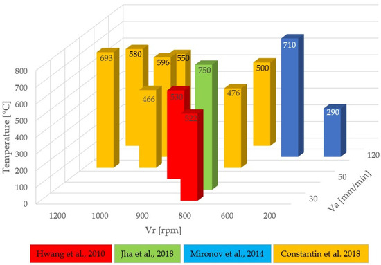
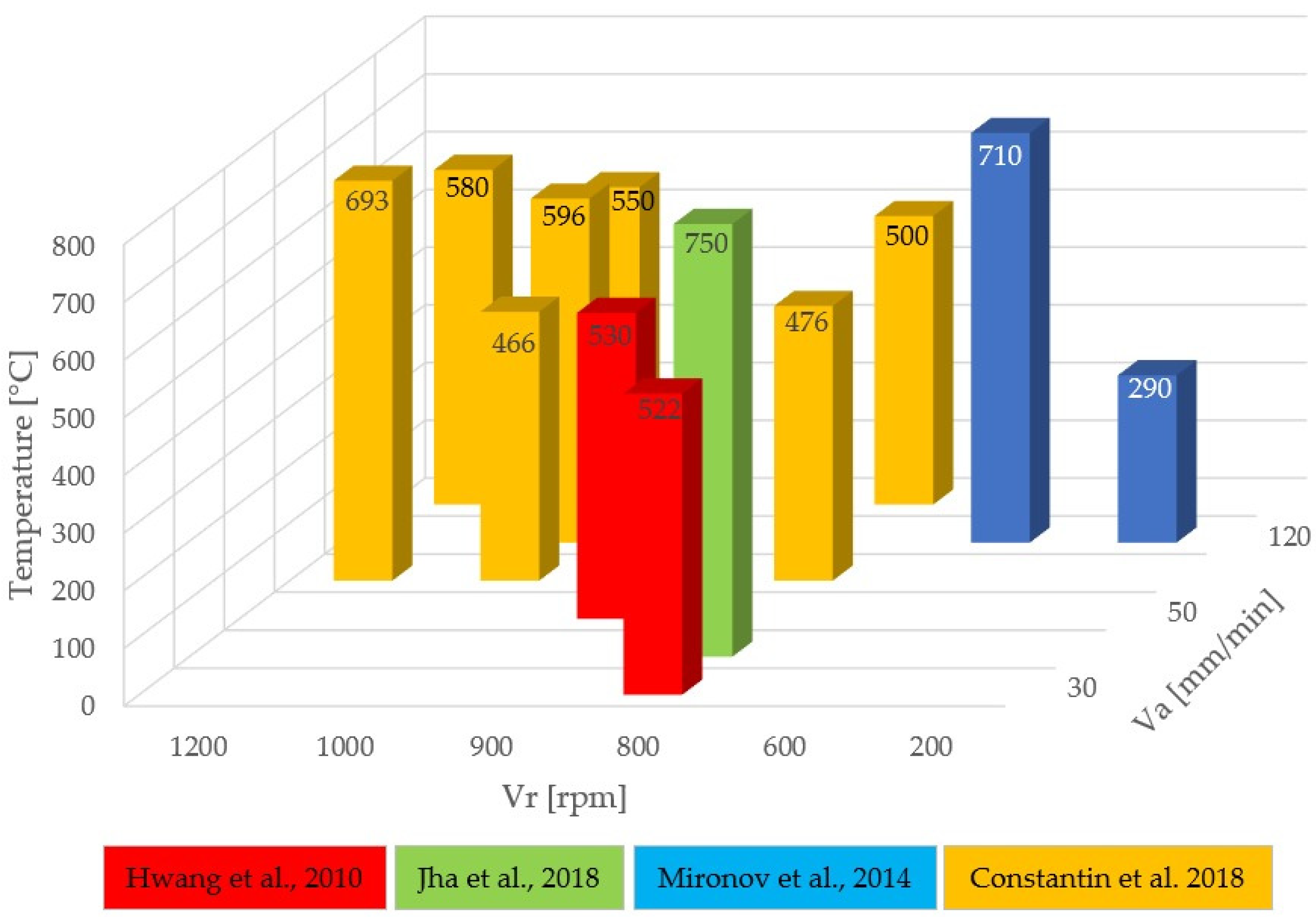
Based on analysis of the previously presented papers, it is clear that process temperatures vary significantly depending on both the rotation speed and the advance speed. For instance, in the friction stir welding of approximately 3 mm plates, the relationship between temperature and welding parameters is illustrated in Figure 5.
Figure 5.
Influence of welding parameters on temperature distribution: red [1]; green [8]; blue [40]; yellow [63].
The temperatures obtained for defect-free joining of pure copper are lower than those for copper alloy joints. At a rotational speed of 800 rpm, temperatures between 476 °C and 522 °C are achieved for pure copper, depending on the feed rate. For pure copper, a temperature range of 460–550 °C has proven ideal for producing defect-free FSW joints with adequate hardness and mechanical strength. Values below 460 °C do not provide sufficient plasticization, while values above 550 °C may lead to coarse-grained structures, negatively affecting joint hardness. In the case of welding a Cu-30%Zn alloy, at a rotational speed of 600 rpm, a temperature of 710 °C resulted in discontinuous recrystallization with a coarse grain structure, leading to low hardness. At lower rotational speeds (200 rpm), the temperatures were insufficient, causing defects due to incomplete heating. For alloy joining at a temperature of 750 °C, achieved with a rotational speed of 800 rpm and a feed rate of 40 mm/min, defect-free joints were obtained.
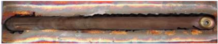
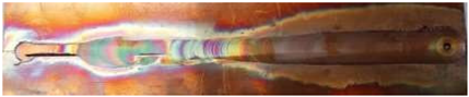
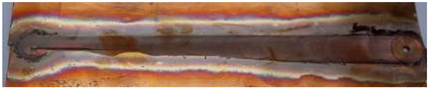
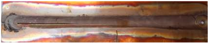
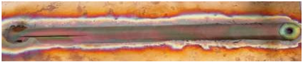
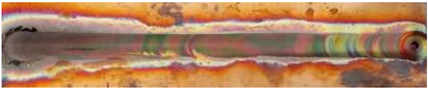
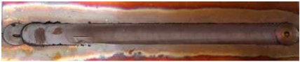
Constantin et al. [63] examined the temperature during the FSW process of pure copper, focusing on its close relationship with process parameters and the formation of defects. Table 4 presents the average values of temperatures measured near the FSW tool for 3 mm thick Cu-DHP, along with the welding process parameters (feed rate and rotational speed) to evaluate the visual morphological aspect of the welded surfaces. Temperatures during the welding process ranged from 466 °C to 693 °C, representing 44% to 64% of copper’s melting temperature. A channel defect appears at the beginning of the joint in all cases, caused by insufficient material plasticization due to low temperatures or improper welding equipment settings. As temperature stabilizes, the visual quality of welded surfaces improves significantly. Research findings suggest that to prevent defects during the friction stir welding of pure copper plates, the welding temperature should be maintained between 550 °C and 650 °C [63]. In this range, the material is plasticized adequately to ensure effective mixing, preventing significant channel and burr-type defects. When temperatures exceed 650 °C, burr formation occurs due to excessive plasticization.
Table 4.
Macroscopic aspect of the joint at different temperatures [63].
Mironov et al. [16] produced welded joints on 1/2H pure Cu plates with a thickness of 4 mm, maintaining a constant traverse speed of 2 mm/s (120 mm/min) for all cases. They achieved temperatures below 0.5 of copper’s melting temperature when the rotational speed ranged from 200 to 500 rpm, where continuous recrystallization was predominantly observed, resulting in a fine-grained microstructure (1–2 μm) in the nugget zone (NZ). For rotational speeds of 600 to 1000 rpm, the temperature exceeded 0.5 of the melting temperature, and discontinuous recrystallization became predominant, leading to a coarse grain structure (10–30 μm) and material softening.
Wang et al. [49] studied strategies for reducing the welding temperature below the aging temperature of a Cu-Cr-Zr alloy with a thickness of 7 mm. The peak temperatures achieved were 830 °C, 711 °C, and 481 °C, respectively. In the first two cases, the temperatures were very high, resulting in a much coarser grain structure compared to the case with the lower temperature. Regarding the microhardness distribution, in the first two cases the microhardness values were below those of the aged Cu-Cr-Zr alloy, while in the third case, the microhardness values exceeded the aging threshold of the material.
In light of the studies carried out, the following conclusions can be drawn regarding the temperature in the friction stir welding (FSW) process for copper and its alloys:
- The temperature in the FSW process influences the recrystallization mechanisms by determining the grain size, grain size distribution in the grain-binding zone, and the homogeneity of the microstructure;
- Higher than optimal temperatures lead to grain growth and decreased mechanical properties;
- For pure copper, the optimum temperature varies between 380 and 600 °C, with most studies recommending around 540–550 °C, i.e., 0.5 × Tm (copper melting temperature), as the optimum welding temperature;
- Copper alloys have a higher maximum temperature during the FSW process (0.8 × Tm) than pure copper.
5. Microstructure
Most of the studies on the microstructure of the joint have been oriented towards the analysis of the microstructure’s evolution in different zones and the analysis of the recrystallization mechanisms as a function of process parameters. Analysis of microstructure in the heat-affected zones and the central zone of the joint includes the study of grain size, the existence of defects, and microstructural texture to understand how the FSW process affects the microstructure of the base material.
In a series of research studies [7,13,14,21,32,34,38,41,45,50,51,64,65,66] it was established that during the FSW process, the microstructure of the base material changes substantially and leads to the emergence of the weld core zone (NZ), the thermally affected zone (HAZ), and the thermo-mechanically affected zone (TMAZ).
Liu et al. [50] investigated the effect of tool rotational speed on the microstructure and mechanical properties of pure copper 1/2H FSW joints, keeping the traverse speed unchanged. They concluded that by increasing the tool rotation speed, the grain size in the NZ and TMAZ increased and the boundary between these zones was blurred. As for the HAZ, the rotational speed had almost no effect on grain size.
Shen et al. [51] investigated the effect of traverse speed on the microstructure and mechanical properties of FSW joints of pure copper 1/2H. Their results show that with increasing traverse speed, the grain size in the NZ decreased, while the TMAZ became much smaller and harder to identify, and the HAZ showed very small changes in grain size.
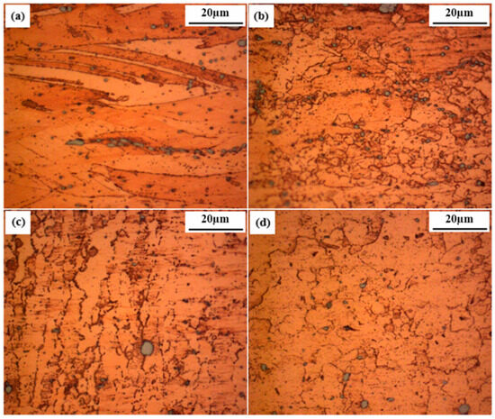
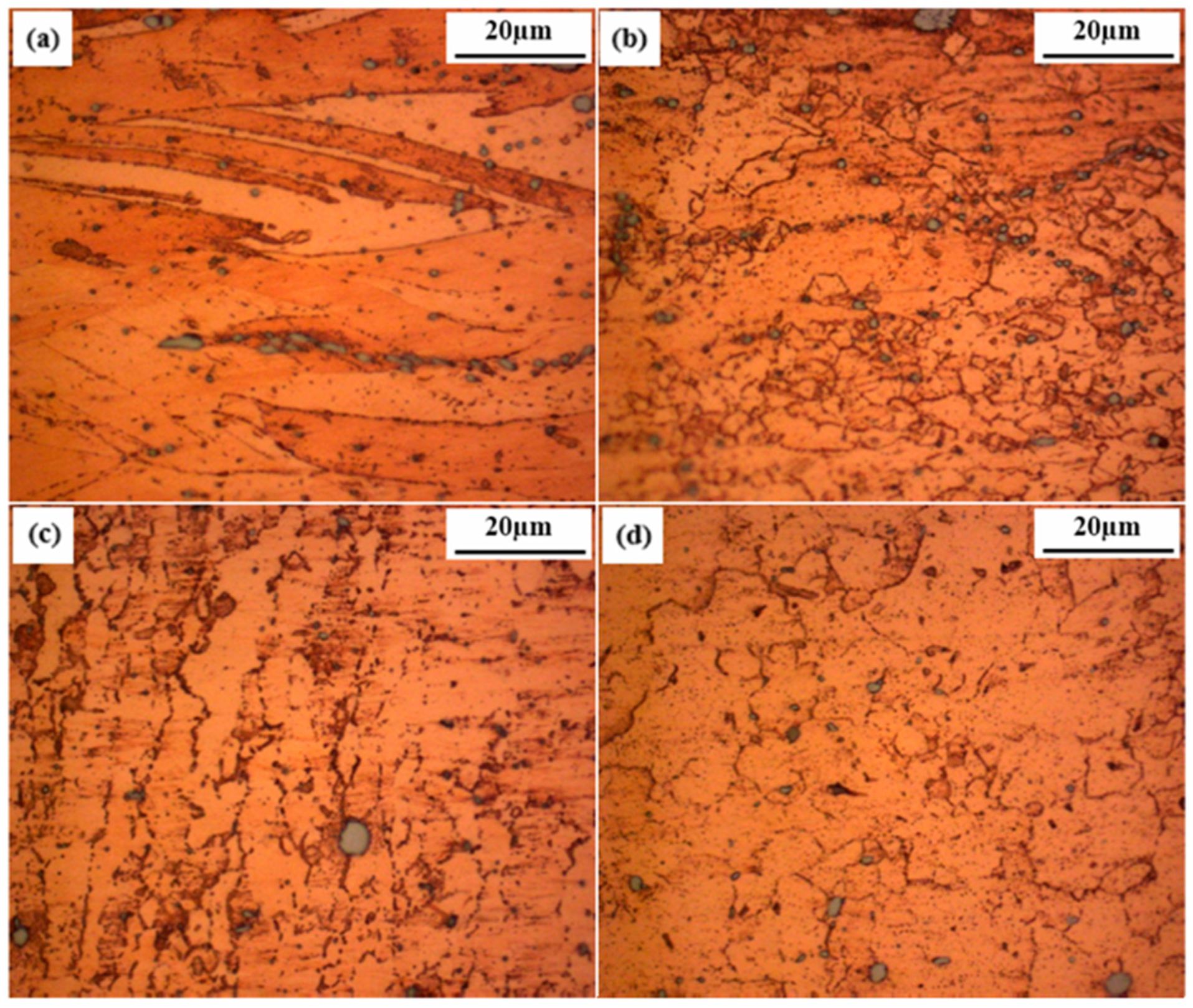
Figure 6 shows that the microstructure of the base material is coarse, while the HAZ exhibits a granular structure similar to that of the base material. The TMAZ is a highly deformed zone, with material flow directed toward the NZ, which is much finer than the other zones due to the high temperatures generated by friction and the plastic deformation of the copper alloy.
Figure 6.
Microstructure of CuCrZr alloy joints: (a) base material; (b) heat-affected zone; (c) thermo-mechanically affected zone; (d) nugget zone [14].
5.1. Nugget Zone
During the FSW process, a fine-grained microstructure is found in the NZ due to recrystallization as a result of plastic deformation and frictional heat. Some researchers have obtained onion ring microstructures in the nugget zone [8,13,15,16,31,43,45,50,54,56].
Barenji [34] studied the influence of heat input on the microstructure evolution and mechanical properties of copper joints made by FSW. He obtained joints with fine and equiaxed grains. The grain size increased with decreasing traverse speeds at a constant rotational speed and with increasing rotational speeds at a constant traverse speed. Thus, the author demonstrated that the weld core (NZ) grain size is mainly affected by the strain rate and maximum temperature during the FSW process. Table 5 shows the NZ grain sizes as a function of the nature and thickness of the material, the tool geometry, and the welding parameters used for different types of copper alloys. In general, for thin materials (1–2 mm), the grain size tends to be smaller because heat transfer is more efficient, and the material is easier to deform plastically. In materials with thicknesses of 2.5–3 mm the hole size shows a larger variation, being strongly influenced by process parameters. In the case of thicker plates (4–7 mm) the grain size tends to be larger, but can be controlled by the appropriate choice of pin shape and process parameters. Alloys with a high zinc content tend to have smaller grains compared to pure copper, due to the refining effect induced by zinc.
Table 5.
Grain size of Cu and Cu alloys in the nugget zone (NZ).
Yaghoubi et Shirazi [21] analyzed the initiation zones, stable growth zones, and unstable crack growth zones for the NZ by scanning electron microscopy (SEM) method under the conditions of a rotational speed of 600 rpm and an advancement speed of 40 mm/min. They observed that several cracks occur during crack initiation that grow to fatigue failure due to the presence of fatigue lines and striations, but pits also occur involving ductile cracking of the material that may be produced unstably or abruptly, in which case the fracture is not brittle. Using transmission electron microscopy (TEM), Heidarzadeh et al. [30] analyzed the NZs of joints between pure copper and brass. They observed that brass exhibits much larger dislocations than pure copper, copper exhibits cell-like dislocations, and in the case of brass the dislocations are entangled structures. We can say that the recovery of dislocations occurs in copper due to its higher energy, which in the case of brass inhibits the transverse sliding of dislocations.
5.2. Thermo-Mechanically Affected Zone
The TMAZ is the zone in which the material has suffered significant plastic deformation and has been exposed to heat, but not enough to produce complete recrystallization. In general, the grains in this zone are elongated and deformed, larger in size than those in the nugget zone.
Barenji [34] affirms that the TMAZ exhibits elongated grains that are larger than those of the NZ, but smaller than those of the base material. By increasing the rotational speed, the TMAZ exhibits an equiaxial recrystallized grain structure due to the higher percentage of heat during FSW, which is similar to the grain structure of the NZ, which makes the boundary between the two zones blurred. Lai et al. [14] find that in the TMAZ there are high heating temperatures due to friction and plastic deformation, resulting in a strongly deformed structure with slip grains along the material flow direction. When welding pure copper plates, the TMAZ exhibits higher hardness and mechanical strength due to microstructure refinement and the formation of fine elongated grains, but compared to the NZ, the hardness and mechanical strength are lower [1,18].
5.3. Heat-Affected Zone
The HAZ is the zone that is affected by heat but does not undergo any plastic deformation. The material in this zone did not undergo pin or tool-shoulder friction, but was thermally influenced by the heat generated by the FSW process, leading to annealing and microstructural changes. Most studies to date have concluded that the microstructure of the HAZ exhibits large grain sizes, sometimes larger than those of the base metal. As far as the parameters of the welding regime are concerned, they do not influence the grain size in this zone much [34,50,51].
6. Mechanical Properties
Studies on the mechanical properties of FSW joints have focused on the evaluation of the tensile strength (UTS) and the elongation of the welded joints, comparative evaluation of the mechanical properties of the joints with those of the base material (the ratio representing the efficiency of the joint), analysis of the hardness distribution in different zones, the behavior of welded joints under cyclic stress, and analyzing the joints’ fatigue resistance.
The tensile strength and microhardness of the weld bead indicate the joint quality of FSW structures. The mechanical properties depend on the microstructure of the FSW seam. The examination of the microhardness distribution and the mechanical strength of the joints leads to the validation of the process parameters and, at the same time, to the validation of the adopted strategy. Table 6 summarizes the mechanical properties of Cu joints produced by the FSW process, obtained by different researchers, namely: ultimate tensile strength (UTS), yield strength (YS), microhardness, and elongation.
Table 6.
Mechanical properties of Cu and Cu alloy FSW joints.
In addition, we calculated the link efficiency, E, with relationship (1):
where UTSFSW is the ultimate tensile strength value of the specimen extracted from the FSW joint and UTSBM is the ultimate tensile strength value of the base material.
6.1. Mechanical Strength
Researchers have focused on identifying the process parameters that lead to a mechanical strength of the material that is greater than or equal to that of the base material.
In the case of the welding of 7 mm thick Cu-Cr-Zr copper alloy plates treated in solid solution at 980 °C for 1.5 h, then rapidly cooled in air or water, Wang et al. [49] observed that the mechanical strength of the joints obtained for the supersaturated plates closely approximated those of the base material for rotation speeds of 30–600 rpm and traverse speeds of 50–100 mm/min. They also made plate joints for which, after solid solution treatment, the plates were aged at 480 °C for 2 h, resulting in mechanical properties far superior to the previous ones; for these, water cooling resulted in specimen breakage in the zone of the base material, while for air cooling the breakage was in the NZ. For the same Cu-Cr-Zr copper alloy, but with a thickness of 2.5 mm, Wang et al. [67] welded aged hot-rolled material plates using FSW, and they kept the traverse speed constant at 50 mm/min and varied the rotational speed between 400 and 600 rpm. They obtained a mechanical strength close to that of the base material by using a rotational speed of 400 rpm, and specimen fracture was in the zone of the base material, while for the other joints, the fracture was in the NZ.
For 5 mm thick pure copper, Khodaverdizadeh et al. [32] performed experiments using the same parameters for two tool configurations, one with a square pin and one with a threaded cylindrical pin. Conducting an analysis on the NZ, the actual joint produced with the square pin shows a higher strength than that obtained by using the threaded cylindrical pin, which is due to the much better material mixing achieved using the square pin. Regarding the welding of 2 mm thick pure Cu and Cu-30Zn plates, Wang et al. [43] made joints using the same tool and rotational speed for both materials, and the traverse speed was 100 mm/min for pure Cu and 200 mm/min for Cu-30Zn. For both materials, they obtained joints with strengths very close to those of the base materials, and the breakage of the specimens was realized in the zone of the base material in both cases, thus observing that by adding zinc to the copper alloy, for the same rotational speed, the traverse speed must be increased to obtain high-quality joints.
6.2. Microhardness
The studies consisted of assessing the hardness distribution in different joint zones, such as the heat-affected zone (HAZ), the thermo-mechanically affected zone (TMAZ), and the nugget zone (NZ). The aim was to understand how process parameters and microstructural variations influence the hardness in these zones and how this correlated with other mechanical properties.
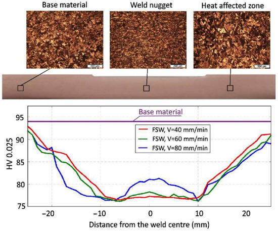
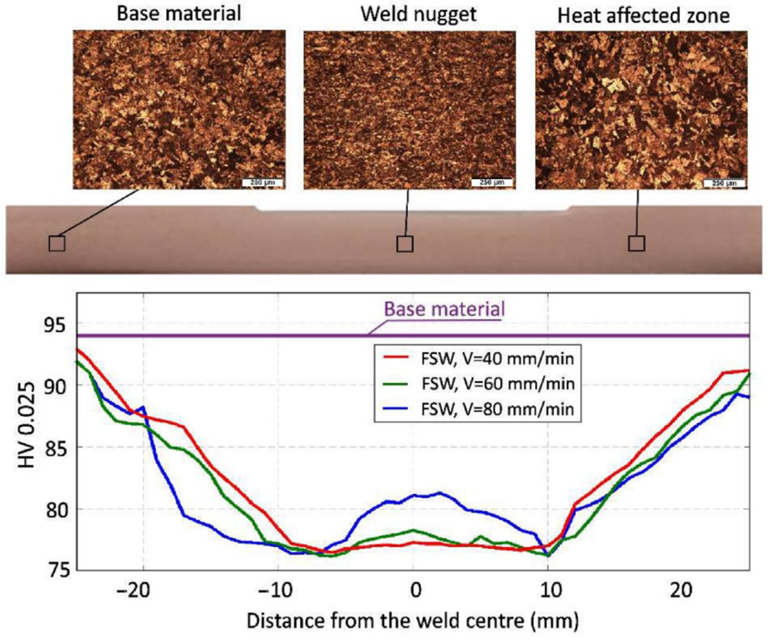
In general, the microhardness profiles have a characteristic “W” shape, typical for FSW joints, a shape that indicates clear differences in hardness across the various zones of the welded joint: NZ, TMAZ, and HAZ, see Figure 7 [55]. Regardless of the traverse speed, the lowest microhardness was obtained in the heat-affected zone (HAZ), and higher traverse speeds lead to greater variations in microhardness due to lower heat input.
Figure 7.
Microstructure and microhardness of Cu-ETP R220 [55].
Kumar et al. [77] buttwelded together two 5 mm thick 1/2H pure copper plates; by keeping the traverse speed constant at 50 mm/min and the rotational speeds between 600 and 800 rpm they obtained the lowest hardness values in the NZs, and at a low heat input (50 mm/min traverse speed and 400 rpm rotational speed) they obtained much higher hardness in the NZ than the base material. At the same time, Sakthivel et al. [45] made hardness measurements of pure copper butt joints with a thickness of 2 mm for which they obtained significant increases of 128–135 HV, much higher than those of the base material, i.e., 106–111 HV, by using an advance speed of 30 mm/min and a rotational speed of 1000 rpm. Kumar et al. [77] studied the influence of FSW tool-pin profile for copper, where they obtained the highest hardness value (105 HV) using a square pin and the lowest hardness value (80 HV) using a hexagonal pin, while the hardness of the base material was 110 HV, and the other tool properties and process parameters were kept the same.
Sun et al. [58] analyzed the effect of adding SiC particles with an average particle size of 5 μm in the gap between two 1/2H copper plates with a thickness of 2 mm. They obtained a uniform hardness distribution in the case of one pass of the FSW tool and a less uniform (W shape) distribution in the case of two passes of the FSW tool. In the experiment where SiC particles were not added, the joint hardness was much lower than that where the particles were added, but the mechanical strength was higher when the SiC particles were not added.
The following conclusions can be drawn from the data summarized in the above table:
- In most cases, the mechanical strength values for welded structures are comparable to or even lower than those of the base material (BM). This reduction in resistance is due to several factors, including microstructural changes that lead to material softening, the presence of microscopic defects, and the influence of processing parameters. The mechanical strength is influenced by many factors, including microstructural changes that lead to material softening, the presence of microscopic defects, and the impact of processing parameters.
- In general, the yield strength (YS) and elongation for welded structures are lower than those of the base material due to the modification of the microstructure that occurs during the FSW process.
- Hardness values are typically lower in the joint area than in the base material due to recrystallisation occurring in the joint area.
- The efficiency of FSW is typically high, with values ranging from 70% to above 100%, depending on the material and plate thickness. Welds of thin materials (less than 5 mm) tend to exhibit a higher welding efficiency, often exceeding 90%.
In the literature, it is recommended that different combinations of parameters of FSW (rotational speed and traverse speed) are adapted to the plate thickness and the quality of the copper alloy to obtain joints with mechanical properties the same as or better than the base material. Thus, for joining pure copper plates these are: Vr = 1000 rpm, Va = 160 mm/min for a 1 mm thickness using a spiral shoulder [29]; Vr = 1200 rpm, Va = 100 mm/min for a 2 mm thickness [43]; Vr = 300 rpm, Va = 250 mm/min for a 3 mm thickness [77]; Vr = 500 rpm, Va = 20 mm/min for a 4 mm thickness [59]; Vr = 400 rpm, Va = 50 mm/min for a 5 mm thickness [31]; Vr = 635 rpm, Va = 19 mm/min for a 6 mm thickness [73]. For copper alloyed plates it is recommended to use: Vr = 1000 rpm, Va = 200 mm/min for a 2 mm thickness [43]; Vr = 1600 rpm, Va = 210 mm/min for a 3 mm thickness [42]; Vr = 400 rpm, Va = 100 mm/min for a 5 mm thickness [38]; Vr = 600 rpm, Va = 50 mm/min for a 7 mm thickness [49]; Vr = 500 rpm, Va = 100 mm/min for a 10–11 mm thickness [76].
7. Conclusions, Bottlenecks, and Future Development Directions
This paper presents a detailed study of papers published to date regarding the FSW of pure copper and its alloys. Therefore, the quality of the joints obtained has been analyzed through the link between their microstructure and mechanical properties with the shape and material of the tool, the process parameters, and the temperature obtained during welding.
7.1. Conclusions
From the works published so far, it has been found that, in the friction stir welding (FSW) of copper and its alloys, it is still difficult to achieve defect-free joints with superior mechanical properties. Due to copper’s high thermal conductivity, it is challenging to maintain a constant optimal temperature in the joint area, which leads to variations in the microstructure and mechanical properties. The results indicate that, in the case of high traverse speeds and low rotational speeds, there is a significant variation in microhardness and the appearance of weak zones in the joint. These variations suggest that the process parameters and the tool geometry must be adjusted for each type of material or copper plate thickness.
The conclusions learned from the analyzed papers are presented below.
In the friction stir welding (FSW) process for pure copper and its alloys, tools with cylindrical pins (threaded or non-threaded) and with flat shoulders have frequently been used because they are simple, efficient, and due to their capacity to produce homogeneous and resisting joints when the process parameters are chosen accordingly.
High-speed steels (HSSs) are frequently used for the manufacturing of tools, although they have limitations when used for welding materials with high thermal conductivity, as copper accelerates tool wear due to the rapid dissipation of heat. However, due to their low cost, good machinability, and acceptable durability, high-speed steels are a common choice in FSW for copper.
Higher rotational and traverse speeds are used for welding thin plates (1–2 mm) because it is easier to achieve the optimal temperature. Therefore, for thin copper plates ranging from 1 to 2 mm in thickness, the optimal spindle speeds are between 800 and 1200 rpm and the traverse speeds are set at 100–200 mm/min to ensure effective heat generation without compromising joint integrity. The thicker plates usually need medium rotational speeds and traverse speeds to ensure complete penetration and superior joint quality.
During the welding process, the temperature must be well controlled to prevent the appearance of defects and to obtain a fine microstructure. For pure copper, the optimal welding temperature is around 540–550 °C. For copper alloys, the temperature can have higher values, but not more than 0.8 of the melting temperature of the material to prevent damage to the microstructure.
The nugget zone (NZ) usually presents a finer granulation than the heat-affected zone (HAZ) due to complete recrystallization, which results in a higher microhardness and tensile strength in the NZ than in the HAZ.
The size of the grains should be smaller for thin plates welded using FSW because the heat transfer is more efficient; for the welding of thicker plates, the grain size is larger, yet it can be controlled by adjusting the process parameters and using appropriate tools.
The mechanical properties in the nugget zone can be comparable to or smaller than those of the base material due to the microstructural transformations that appear during the welding process. In almost every study, the test samples exposed to traction break in the HAZ.
The copper alloys, such as Cu-Zn and Cu-Cr-Zr, present a higher microhardness and mechanical strength than pure copper because of the presence of the alloying elements which improve the material’s mechanical properties.
7.2. Bottlenecks
Achieving good mechanical properties in the nugget zone (NZ), similar to or surpassing those of the base material, remains challenging due to microstructural transformations that occur during welding. Most studies indicate that fractures commonly occur in the heat-affected zone (HAZ) during tensile tests, as this region is often weaker. Additionally, copper alloys like Cu-Zn and Cu-Cr-Zr tend to show increased microhardness and mechanical strength compared to pure copper, largely due to the reinforcing effects of alloying elements. However, it is difficult to maintain these enhanced properties uniformly across joints in different copper alloys, especially under varied welding conditions and process parameters.
7.3. Future Development Direction
Future research will explore more efficient methods for real-time temperature monitoring and control in the welding zone to achieve defect-free joints. Additionally, hybrid processes, such as tungsten inert gas (TIG), laser-assisted FSW, FSW with active cooling, or FSW in a controlled environment, could also be considered. These techniques may offer additional advantages, such as better temperature control, a reduction in defects, and improvement in the mechanical properties of the joints.
Future studies may consider the development of advanced numerical models to simulate the FSW process, including temperature-dependent material properties, heat transfer coefficients, and temperature-dependent friction coefficients. Numerical models can reduce experimentation periods and, based on them, the process can be optimized.
Author Contributions
Conceptualization, R.N.B. and D.M.I.; methodology, D.M.I. and R.N.B.; validation, Y.D., M.D., C.B. and E.L.N.; investigation, R.N.B. and D.M.I.; resources, R.N.B. and D.M.I.; writing—original draft preparation, R.N.B.; writing—review and editing, D.M.I.; visualization, Y.D., M.D., C.B. and E.L.N.; supervision, Y.D., M.D., C.B. and E.L.N.; project administration, D.M.I. and R.N.B. All authors have read and agreed to the published version of the manuscript.
Funding
This research received no external funding.
Institutional Review Board Statement
Not applicable.
Informed Consent Statement
Not applicable.
Data Availability Statement
The corresponding author will provide the data used in this work upon reasonable request.
Conflicts of Interest
The authors declare no conflicts of interest.
References
- Hwang, Y.M.; Fan, P.L.; Lin, C.H. Experimental study on Friction Stir Welding of copper metals. J. Mater. Process Technol. 2010, 210, 1667–1672. [Google Scholar] [CrossRef] [Scilit]
- Dumitra Clej, D.; Popa, D.F.; Popa, G.A.; Jigau, C.; Ghimpusan, M.; Nechifor, A.C. Estimating Performance Parameters to Determine Copper Using Atomic Absorbtion Spectrometry. Bull. Ser. B 2017, 79, 101–110. [Google Scholar]
- Heidarzadeh, A.; Testik, Ö.M.; Güleryüz, G.; Barenji, R.V. Development of a fuzzy logic based model to elucidate the effect of FSW parameters on the ultimate tensile strength and elongation of pure copper joints. J. Manuf. Process. 2020, 53, 250–259. [Google Scholar] [CrossRef] [Scilit]
- Thomas, W.M.; Nicholas, E.D.; Needham, J.C.; Murch, M.G.; Temple-Smith, P.; Dawes, C.J. Friction Welding. United Kingdom; 1995, GB Patent Application No. 9125978, 1991. US Patent No. 5460317, 24 October 1995. [Google Scholar]
- Chen, B.; Chen, K.; Hao, W.; Liang, Z.; Yao, J.; Zhang, L.; Shan, A. Friction stir welding of small-dimension Al3003 and pure Cu pipes. J. Mater. Process Technol. 2015, 223, 48–57. [Google Scholar] [CrossRef] [Scilit]
- Meran, C. The joint properties of brass plates by friction stir welding. Mater. Des. 2006, 27, 719–726. [Google Scholar] [CrossRef] [Scilit]
- Sun, Y.; Gong, W.; Li, Y.; Liu, W.; Sun, S.; Zhu, R.; Feng, J. Effect of rotation speed on microstructure and mechanical properties of bobbin tool friction stir welded T2 copper. Mater. Today Commun. 2023, 35, 106365. [Google Scholar] [CrossRef] [Scilit]
- Jha, K.; Kumar, S.; Nachiket, K.; Bhanumurthy, K.; Dey, G.K. Friction Stir Welding (FSW) of Aged CuCrZr Alloy Plates. Metall. Mater. Trans. A Phys. Metall. Mater. Sci. 2018, 49, 223–234. [Google Scholar] [CrossRef] [Scilit]
- Sato, Y.S.; Kokawa, H.; Enomoto, M.; Jogan, S. Microstructural Evolution of 6063 Aluminum during Friction-Stir Welding. Met. Mater. Trans. A 1999, 30, 2429–2437. [Google Scholar] [CrossRef] [Scilit]
- Colligan, B.Y.K. Material Flow Behavior during Friction Stir Welding of Aluminum. Weld. Res. 1999, 229–237. [Google Scholar]
- Mishra, R.S.; Ma, Z.Y. Friction stir welding and processing. Mater. Sci. Eng. R Rep. 2005, 50, 1–78. [Google Scholar] [CrossRef] [Scilit]
- Szachogłuchowicz, I.; Śnieżek, L.; Wójcik, A. Mechanical Properties of the AlCu4Mg1 Alloy Joint Manufactured by Underwater Friction Stir Welding. Materials 2024, 17, 1722. [Google Scholar] [CrossRef] [Scilit] [PubMed]
- Sun, Y.F.; Fujii, H. Investigation of the welding parameter dependent microstructure and mechanical properties of friction stir welded pure copper. Mater. Sci. Eng. A 2010, 527, 6879–6886. [Google Scholar] [CrossRef] [Scilit]
- Lai, R.; He, D.; He, G.; Lin, J.; Sun, Y. Study of the microstructure evolution and properties response of a friction-stir-welded copper-chromium-zirconium alloy. Metals 2017, 7, 381. [Google Scholar] [CrossRef] [Scilit]
- Xue, P.; Xie, G.M.; Xiao, B.L.; Ma, Z.Y.; Geng, L. Effect of heat input conditions on microstructure and mechanical properties of friction-stir-welded pure copper. Metall. Mater. Trans. A Phys. Metall. Mater. Sci. 2010, 41, 2010–2021. [Google Scholar] [CrossRef] [Scilit]
- Mironov, S.; Inagaki, K.; Sato, Y.S.; Kokawa, H. Microstructural evolution of pure copper during friction-stir welding. Philos. Mag. 2015, 95, 367–381. [Google Scholar] [CrossRef] [Scilit]
- Kumar, N.; Dhuria, G.K.; Singh, R. Evaluation of Tensile Strength in Friction Stir Welded Aluminum alloy 6101-T6 and commercially pure Copper joints. Mater. Today Proc. 2018, 5, 19230–19236. [Google Scholar] [CrossRef] [Scilit]
- Karrar, G.; Galloway, A.; Toumpis, A.; Li, H.; Al-Badour, F. Microstructural characterisation and mechanical properties of dissimilar AA5083-copper joints produced by friction stir welding. J. Mater. Res. Technol. 2020, 9, 11968–11979. [Google Scholar] [CrossRef] [Scilit]
- Mao, Y.; Ni, Y.; Xiao, X.; Qin, D.; Fu, L. Microstructural characterization and mechanical properties of micro friction stir welded dissimilar Al/Cu ultra-thin sheets. J. Manuf. Process. 2020, 60, 356–365. [Google Scholar] [CrossRef] [Scilit]
- Muhammad, N.A.; Wu, C.S. Evaluation of capabilities of ultrasonic vibration on the surface, electrical and mechanical behaviours of aluminium to copper dissimilar friction stir welds. Int. J. Mech. Sci. 2020, 183, 105784. [Google Scholar] [CrossRef] [Scilit]
- Yaghoubi, S.; Shirazi, A. Mechanical properties and corrosion behavior of friction stir welded copper plates under shielding gas. Int. J. Fatigue 2021, 152, 106419. [Google Scholar] [CrossRef] [Scilit]
- Soni, N.; Yaocheng, Y.; Kumar, A.; Caihong, Y.; Li, L.; Singh, A.; Lin, Y. Electrochemical and surface studies of 0.95 Mg-Al-alloy and pure copper joints prepared using friction stir welding with low-medium-high tool travel speeds. Int. J. Electrochem. Sci. 2019, 14, 8949–8972. [Google Scholar] [CrossRef] [Scilit]
- Zhou, L.; Li, G.H.; Zhang, R.X.; Zhou, W.L.; He, W.X.; Huang, Y.X.; Song, X. Microstructure evolution and mechanical properties of friction stir spot welded dissimilar aluminum-copper joint. J. Alloys Compd. 2019, 775, 372–382. [Google Scholar] [CrossRef] [Scilit]
- Aliha, M.R.M.; Kalantari, M.H.; Ghoreishi, S.M.N.; Torabi, A.R.; Etesam, S. Mixed mode I/II crack growth investigation for bi-metal FSW aluminum alloy AA7075-T6/pure copper joints. Theor. Appl. Fract. Mech. 2019, 103, 102243. [Google Scholar] [CrossRef] [Scilit]
- Osman, N.; Sajuri, Z.; Baghdadi, A.H.; Omar, M.Z. Effect of process parameters on interfacial bonding properties of aluminium–copper clad sheet processed by multi-pass friction stir-welding technique. Metals 2019, 9, 1159. [Google Scholar] [CrossRef] [Scilit]
- Lader, S.K.; Baruah, M.; Ballav, R. Significance of underwater friction stir welding on the weld integrity of thin sheets of aluminum (AA1050-O) and brass (CuZn34) joints. Mater. Sci. Eng. A 2023, 865, 144627. [Google Scholar] [CrossRef] [Scilit]
- Daniela Iordache, M.; Badulescu, C.; Diakhate, M.; Constantin, M.A.; Nitu, E.L.; Demmouche, Y.; Dhondt, M.; Negrea, D. A numerical strategy to identify the FSW process optimal parameters of a butt-welded joint of quasi-pure copper plates: Modeling and experimental validation. Int. J. Adv. Manuf. Technol. 2021, 115, 2505–2520. [Google Scholar] [CrossRef] [Scilit]
- Salahi, S.; Yapici, G.G. Fatigue Behavior of Friction Stir Welded Joints of Pure Copper with Ultra-fine Grains. Procedia Mater. Sci. 2015, 11, 74–78. [Google Scholar] [CrossRef] [Scilit]
- Galvão, I.; Leal, R.M.; Rodrigues, D.M.; Loureiro, A. Influence of tool shoulder geometry on properties of friction stir welds in thin copper sheets. J. Mater. Process Technol. 2013, 213, 129–135. [Google Scholar] [CrossRef] [Scilit]
- Heidarzadeh, A.; Laleh, H.M.; Gerami, H.; Hosseinpour, P.; Shabestari, M.J.; Bahari, R. The origin of different microstructural and strengthening mechanisms of copper and brass in their dissimilar friction stir welded joint. Mater. Sci. Eng. A 2018, 735, 336–342. [Google Scholar] [CrossRef] [Scilit]
- Xie, G.M.; Ma, Z.Y.; Geng, L. Development of a fine-grained microstructure and the properties of a nugget zone in friction stir welded pure copper. Scr. Mater. 2007, 57, 73–76. [Google Scholar] [CrossRef] [Scilit]
- Khodaverdizadeh, H.; Heidarzadeh, A.; Saeid, T. Effect of tool pin profile on microstructure and mechanical properties of friction stir welded pure copper joints. Mater. Des. 2013, 45, 265–270. [Google Scholar] [CrossRef] [Scilit]
- Lai, R.; Li, X.; He, D.; Lin, J.; Li, J.; Lei, Q. Microstructures evolution and localized properties variation of a thick friction stir welded CuCrZr alloy plate. J. Nucl. Mater. 2018, 510, 70–79. [Google Scholar] [CrossRef] [Scilit]
- Barenji, R.V. Influence of heat input conditions on microstructure evolution and mechanical properties of friction stir welded pure copper joints. Trans. Indian Inst. Met. 2016, 69, 1077–1085. [Google Scholar] [CrossRef] [Scilit]
- Heidarzadeh, A.; Motalleb-nejad, P.; Barenji, R.V.; Khalili, V.; Güleryüz, G. The origin of the maximum hardness of the friction stir welded single-phase Cu-Zn plates: RSM, EBSD, and TEM investigation. Mater. Chem. Phys. 2019, 223, 9–15. [Google Scholar] [CrossRef] [Scilit]
- Sadhu, A.; Sarkar, S.; Chattopadhyay, A.; Mypati, O.; Pal, S.K.; Nath, A.K. Effect of Laser Shock Peening on micro-structure and mechanical properties of Friction Stir Welded CuCrZr sheets. Mater. Sci. Eng. A 2022, 831, 142238. [Google Scholar] [CrossRef] [Scilit]
- Heidarzadeh, A.; Saeid, T.; Klemm, V. Microstructure, texture, and mechanical properties of friction stir welded commercial brass alloy. Mater. Charact. 2016, 119, 84–91. [Google Scholar] [CrossRef] [Scilit]
- Xie, G.M.; Ma, Z.Y.; Geng, L. Effects of friction stir welding parameters on microstructures and mechanical properties of brass joints. Mater. Trans. 2008, 49, 1698–1701. [Google Scholar] [CrossRef] [Scilit]
- Heidarzadeh, A.; Barenji, R.V.; Khalili, V.; Güleryüz, G. Optimizing the friction stir welding of the α/β brass plates to obtain the highest strength and elongation. Vacuum 2019, 159, 152–160. [Google Scholar] [CrossRef] [Scilit]
- Mironov, S.; Inagaki, K.; Sato, Y.S.; Kokawa, H. Development of grain structure during friction-stir welding of Cu-30Zn brass. Philos. Mag. 2014, 94, 3137–3148. [Google Scholar] [CrossRef] [Scilit]
- Park, H.S.; Kimura, T.; Murakami, T.; Nagano, Y.; Nakata, K.; Ushio, M. Microstructures and mechanical properties of friction stir welds of 60% Cu-40% Zn copper alloy. Mater. Sci. Eng. A 2004, 371, 160–169. [Google Scholar] [CrossRef] [Scilit]
- Çam, G.; Serindaǧ, H.T.; Çakan, A.; Mistikoglu, S.; Yavuz, H. The effect of weld parameters on friction stir welding of brass plates. Materwiss Werksttech 2008, 39, 394–399. [Google Scholar] [CrossRef] [Scilit]
- Wang, Y.F.; An, J.; Yin, K.; Wang, M.S.; Li, Y.S.; Huang, C.X. Ultrafine-Grained Microstructure and Improved Mechanical Behaviors of Friction Stir Welded Cu and Cu–30Zn Joints. Acta Metall. Sin. (Engl. Lett.) 2018, 31, 878–886. [Google Scholar] [CrossRef] [Scilit]
- Lin, J.W.; Chang, H.C.; Wu, M.H. Comparison of mechanical properties of pure copper welded using friction stir welding and tungsten inert gas welding. J. Manuf. Process. 2014, 16, 296–304. [Google Scholar] [CrossRef] [Scilit]
- Sakthivel, T.; Mukhopadhyay, J. Microstructure and mechanical properties of friction stir welded copper. J. Mater. Sci. 2007, 42, 8126–8129. [Google Scholar] [CrossRef] [Scilit]
- Khodaverdizadeh, H.; Mahmoudi, A.; Heidarzadeh, A.; Nazari, E. Effect of friction stir welding (FSW) parameters on strain hardening behavior of pure copper joints. Mater. Des. 2012, 35, 330–334. [Google Scholar] [CrossRef] [Scilit]
- Raju, L.S.; Venu, B. Meta-heuristic optimization of copper friction stir weldments. INCAS Bull. 2020, 12, 163–171. [Google Scholar] [CrossRef] [Scilit]
- Raju, L.S.; Kumar, A.; Prasad, S.R. Microstructure and mechanical properties of friction stir welded pure copper. Appl. Mech. Mater. 2014, 592–594, 499–503. [Google Scholar] [CrossRef] [Scilit]
- Wang, Y.D.; Xue, P.; Liu, F.C.; Wu, L.H.; Zhang, H.; Zhang, Z.; Ni, D.; Xiao, B.; Ma, Z. Influence of processing innovations on joint strength improvements in friction stir welded high strength copper alloys. Mater. Sci. Eng. A 2023, 872, 144983. [Google Scholar] [CrossRef] [Scilit]
- Liu, H.J.; Shen, J.J.; Huang, Y.X.; Kuang, L.Y.; Liu, C.; Li, C. Effect of tool rotation rate on microstructure and mechanical properties of friction stir welded copper. Sci. Technol. Weld. Join. 2009, 14, 577–583. [Google Scholar] [CrossRef] [Scilit]
- Shen, J.J.; Liu, H.J.; Cui, F. Effect of welding speed on microstructure and mechanical properties of friction stir welded copper. Mater. Des. 2010, 31, 3937–3942. [Google Scholar] [CrossRef] [Scilit]
- Xue, P.; Xiao, B.L.; Zhang, Q.; Ma, Z.Y. Achieving friction stir welded pure copper joints with nearly equal strength to the parent metal via additional rapid cooling. Scr. Mater. 2011, 64, 1051–1054. [Google Scholar] [CrossRef] [Scilit]
- Heidarzadeh, A.; Saeid, T. Correlation between process parameters, grain size and hardness of friction-stir-welded Cu–Zn alloys. Rare Metals 2018, 37, 388–398. [Google Scholar] [CrossRef] [Scilit]
- Xie, G.M.; Ma, Z.Y.; Geng, L. Partial recrystallization in the nugget zone of friction stir welded dual-phase Cu-Zn alloy. Philos. Mag. 2009, 89, 1505–1516. [Google Scholar] [CrossRef] [Scilit]
- Machniewicz, T.; Nosal, P.; Korbel, A.; Hebda, M. Effect of FSW traverse speed on mechanical properties of copper plate joints. Materials 2020, 13, 1937. [Google Scholar] [CrossRef] [Scilit]
- Teimurnezhad, J.; Pashazadeh, H.; Masumi, A. Effect of shoulder plunge depth on the weld morphology, macrograph and microstructure of copper FSW joints. J. Manuf. Process. 2016, 22, 254–259. [Google Scholar] [CrossRef] [Scilit]
- Scutelnicu, E.; Birsan, D.; Cojocaru, R. Research on Friction Stir Welding and Tungsten Inert Gas assisted Friction Stir Welding of Copper. Recent Adv. Manuf. Eng. 2012, 1, 97–102. [Google Scholar]
- Sun, Y.F.; Fujii, H. The effect of SiC particles on the microstructure and mechanical properties of friction stir welded pure copper joints. Mater. Sci. Eng. A 2011, 528, 5470–5475. [Google Scholar] [CrossRef] [Scilit]
- Pashazadeh, H.; Teimournezhad, J.; Masoumi, A. Experimental investigation on material flow and mechanical properties in friction stir welding of copper sheets. Int. J. Adv. Manuf. Technol. 2017, 88, 1961–1970. [Google Scholar] [CrossRef] [Scilit]
- Constantin, M.A.; Boşneag, A.; Nitu, E.; Iordache, M. Experimental investigations of tungsten inert gas assisted friction stir welding of pure copper plates. IOP Conf. Ser. Mater. Sci. Eng. 2017, 252, 012038. [Google Scholar] [CrossRef] [Scilit]
- Constantin, M.A.; Bosneag, A.; Nitu, E.; Iordache, M. Orientation of process parameter values of TIG assisted FSW of copper to obtain improved mechanical properties. IOP Conf. Ser. Mater. Sci. Eng. 2018, 400, 022017. [Google Scholar] [CrossRef] [Scilit]
- Constantin, M.A.; Boşneag, A.; Niţu, E.; Iordache, M. Comparative study on microhardness between friction stir welding and tungsten inert gas assisted friction stir welding of pure copper. In MATEC Web of Conferences; EDP Sciences: Les Ulis, France, 2018. [Google Scholar]
- Constantin, M.A.; Nitu, E.L.; Iordache, D.M.; Badulescu, C. Study on the influence of technological parameters on the friction stir butt welding process of pure copper plates. IOP Conf. Ser. Mater. Sci. Eng. 2020, 968, 012013. [Google Scholar] [CrossRef] [Scilit]
- Ozer, A.; Sik, A.; Cevik, B.; Ozer, M. The effect of friction stir welding parameters on microstructure and fatigue strength of CuZn37 brass alloys. Kov. Mater.-Met. Mater. 2017, 55, 107–114. [Google Scholar] [CrossRef] [Scilit]
- Krishna, S.C.; Karthick, N.K.; Karthik, G.M.; Damodaram, R.; Jha, A.K.; Pant, B.; Cherian, R.M. Effect of Post-Weld Heat Treatment on the Microstructure and Mechanical Properties of Friction Stir Welds of Cu–Cr–Zr–Ti Alloy. Metallogr. Microstruct. Anal. 2018, 7, 703–710. [Google Scholar] [CrossRef] [Scilit]
- Nia, A.A.; Shirazi, A. Effects of different friction stir welding conditions on the microstructure and mechanical properties of copper plates. Int. J. Miner. Metall. Mater. 2016, 23, 799–809. [Google Scholar] [CrossRef] [Scilit]
- Wang, Y.D.; Zhu, S.Z.; Xie, G.M.; Wu, L.H.; Xue, P.; Ni, D.R.; Xiao, B.L.; Ma, Z.Y. Realising equal-strength welding with good conductivity in Cu–Cr–Zr alloy via friction stir welding. Sci. Technol. Weld. Join. 2021, 26, 448–454. [Google Scholar] [CrossRef] [Scilit]
- Zhang, H.; Miao, J.; Wang, K.; Yu, C.; Mei, R.; Lin, X. Interfacial reaction characteristics and mechanisms during dissimilar friction stir lap welding of pure copper and Al0.1CoCrFeNi alloy. J. Mater. Res. Technol. 2024, 31, 1665–1674. [Google Scholar] [CrossRef] [Scilit]
- Agapiou, J.S. Filling friction stir welding in-process exit holes in copper squirrel cage rotors for electric motors. Procedia Manuf. 2021, 53, 802–813. [Google Scholar] [CrossRef] [Scilit]
- Zhang, C.; Qin, Z.; Rong, C.; Shi, W.; Wang, S. The preliminary exploration of micro-friction stir welding process and material flow of copper and brass ultra-thin sheets. Materials 2020, 13, 2401. [Google Scholar] [CrossRef] [Scilit]
- Lim, Y.; Lee, K.; Moon, S. Effects of a post-weld heat treatment on the mechanical properties and microstructure of a friction-stir-welded beryllium-copper alloy. Metals 2019, 9, 461. [Google Scholar] [CrossRef] [Scilit]
- Nakata, K. Friction stir welding of copper and copper alloy. J. Jpn. Weld. Soc. 2005, 19, 929–933. [Google Scholar] [CrossRef] [Scilit]
- Kumar, R.; Singh, R.; Mehta, N.K.; Avula, D.; Dwivedi, D.K. Effect of Friction Stir Welding on Microstructural and Mechanical Properties of Copper Alloy SEE PROFILE Effect of Friction Stir Welding on Microstructural and Mechanical Properties of Copper Alloy [Internet]. 2011. Available online: https://www.researchgate.net/publication/265408376 (accessed on 17 July 2024).
- Gheisari, Y.; Pashazadeh, H.; Teimournezhad, J.; Masoumi, A. Weld defect formation in FSWed coppers. J. Mater. Eng. Perform. 2014, 23, 2000–2006. [Google Scholar] [CrossRef] [Scilit]
- Surekha, K.; Els-Botes, A. Development of high strength, high conductivity copper by friction stir processing. Mater. Des. 2011, 32, 911–916. [Google Scholar] [CrossRef] [Scilit]
- He, D.; Lai, R.; Xu, S.; Yang, K.; Ye, S.; Wang, J.; Zhu, J.M.; Su, B. Microstructure and mechanical properties of Cu-Cr-Zr alloy by friction stir welding. Adv. Mat. Res. 2013, 602–604, 608–611. [Google Scholar] [CrossRef] [Scilit]
- Kumar, A.; Raju, L.S. Influence of tool pin profiles on friction stir welding of copper. Mater. Manuf. Processes 2012, 27, 1414–1418. [Google Scholar] [CrossRef] [Scilit]
- Saukkonen, T.; Savolainen, K.; Mononen, J.; Hänninen, H.; Koivula, J. Friction Stir Weldability of Copper Alloys [Internet]. 2004. Available online: https://www.researchgate.net/publication/291765614 (accessed on 17 July 2024).

Disclaimer/Publisher’s Note: The statements, opinions and data contained in all publications are solely those of the individual author(s) and contributor(s) and not of MDPI and/or the editor(s). MDPI and/or the editor(s) disclaim responsibility for any injury to people or property resulting from any ideas, methods, instructions or products referred to in the content. |
© 2024 by the authors. Licensee MDPI, Basel, Switzerland. This article is an open access article distributed under the terms and conditions of the Creative Commons Attribution (CC BY) license (https://creativecommons.org/licenses/by/4.0/).