Research on Partial Discharge Signal Detection Technology of Cable Joints Based on a Dynamic Multi-Notch Method


Abstract
1. Introduction
2. Detection Principle and Technical Scheme
2.1. Detection Principle
2.2. System Design
2.3. Signal Detection Steps
3. Experiments and Analysis
3.1. Experimental Platform Construction
3.1.1. Test Piece Preparation Unit
- ♦
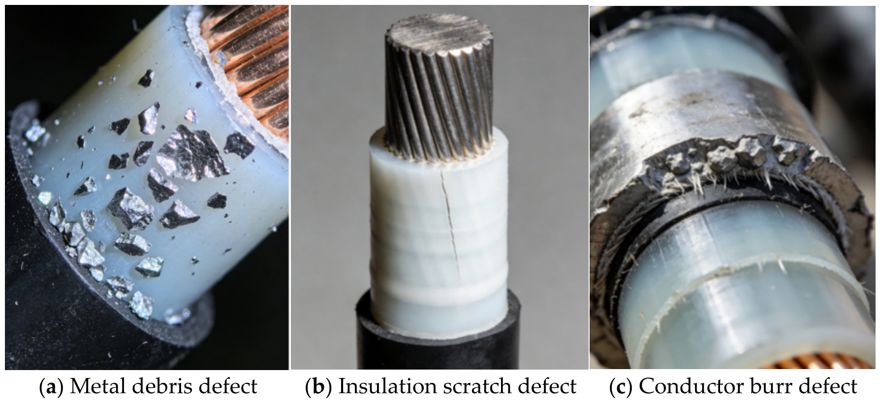
- Metal debris defects: Copper debris (simulating residual metal impurities in construction) with particle sizes of 1 mm, 2 mm and 5 mm were used, 5 pieces for each size, evenly embedded in the upper middle part of the joint insulation layer to simulate partial discharge caused by metal impurities inside the insulation.
- ♦
- Insulation scratch defects: Prepared by precision mechanical processing, with scratch lengths of 2 mm, 3 mm and 5 mm, and a uniform depth of 0.5 mm (about 1/9 of the insulation layer thickness, without breaking down the insulation). The scratch direction is parallel to the cable axis to simulate mechanical scratches on the insulation layer during laying.
- ♦
- Conductor burr defects: Aluminum burrs (the same material as the cable conductor) with heights of 1 mm, 2 mm and 3 mm, and a root width of 0.5~1 mm, directly processed on the surface of the cable conductor to simulate tip discharge defects caused by poor conductor processing technology.

3.1.2. High-Voltage Excitation Unit
3.1.3. Electromagnetic Interference Simulation Unit
- ♦
- Mobile communication signal simulator(Siglent Technologies Co., Ltd., Shenzhen, China, Model: SSG3032X-IQE): Outputs dual-band continuous wave signals of 900 MHz (GSM900) and 1800 MHz (DCS1800) with continuously adjustable amplitude and GSM signal modulation mode, simulating on-site mobile communication electromagnetic wave interference.
- ♦
- Industrial equipment radiation simulator(Rigol Technologies Inc., Beijing, China, Model: DSG836A): Outputs 400~800 MHz broadband interference signals with continuously adjustable amplitude and a spectrum flatness of ≤±1 dB, simulating electromagnetic radiation interference from industrial frequency converters, electric welders, high-voltage switch cabinets and other equipment. The two types of interference sources can be turned on independently or synchronously to realize the simulation of complex electromagnetic environments with single/multiple interference source superposition.
3.1.4. Signal Detection Unit
3.1.5. Data Acquisition and Analysis Unit
3.2. Experimental Test and Analysis
3.2.1. Signal Extraction Effect Experiment
3.2.2. Anti-Interference Performance Experiment
- ♦
- Single-interference source test: The mobile communication signal simulator and the industrial equipment radiation simulator were used as independent interference sources. The interference amplitude was gradually increased, 20 groups of tests were carried out for each amplitude level, and the detection accuracy was recorded.
- ♦
- Multi-interference source superposition test: The mobile communication signal simulator and the industrial equipment radiation simulator were turned on at the same time to simulate strong composite electromagnetic interference, 30 groups of tests were carried out, and the detection accuracy and signal extraction effect were recorded.
- ♦
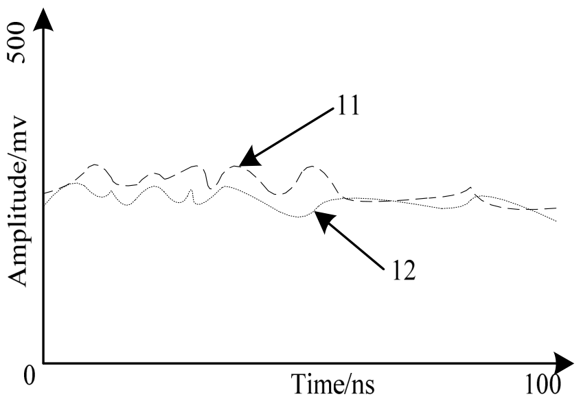
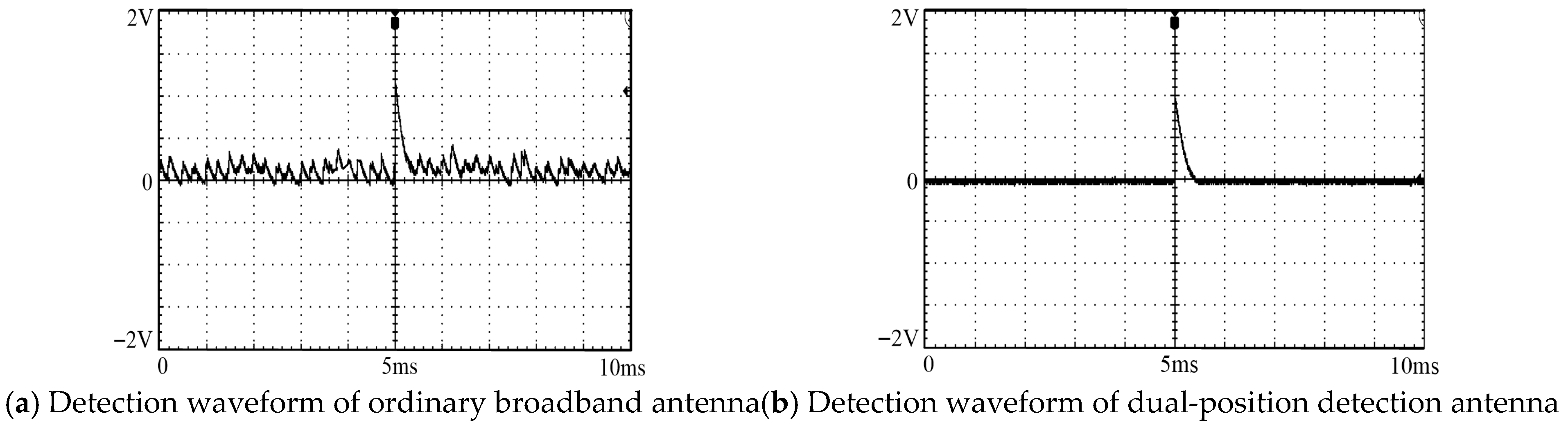
- Single-interference source test: When the interference amplitude is small, the detection accuracy of the ordinary broadband antenna is about 60~70%. With the increase in interference amplitude, the detection accuracy decreases rapidly. When the interference amplitude reaches −5 dBm, the detection accuracy drops to below 40%. Its detection waveform is shown in Figure 11a, where the baseband interference signal completely covers the partial discharge pulse and cannot be identified; while the dual-position detection antenna maintains a detection accuracy of 90.0~95.0%, all while under single interference, and the waveform is shown in Figure 11b, where the noise is effectively filtered out, the partial discharge pulse signal is clear and distinguishable, and only the amplitude is slightly reduced. Experimental verification shows that the proposed algorithm can maintain a detection accuracy of more than 85% when the amplitude of mobile communication interference reaches 2 dBm and the amplitude of industrial equipment radiation interference reaches 5 dBm. When the interference amplitude exceeds the above ranges (mobile communication > 2 dBm, industrial radiation > 5 dBm), the detection accuracy will drop below 80%, which is lower than the allowable threshold for engineering applications. Accordingly, the maximum tolerable interference levels of the algorithm are defined as follows: mobile communication interference ≤ 2 dBm and industrial equipment radiation interference ≤ 5 dBm.
- ♦
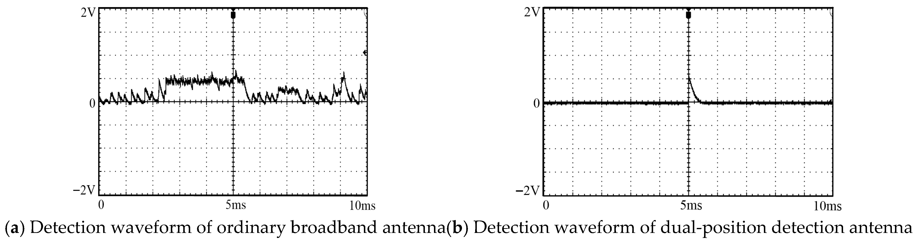
- Multi-interference source superposition test: After the superposition of mobile communication signals and industrial equipment radiation signals, the interference frequency band covers 400~1800 MHz with a more complex spectrum. The detection waveform of the ordinary broadband antenna is shown in Figure 12a, where the noise intensity is greatly increased, the partial discharge signal is completely submerged, and the detection accuracy is only about 25%. The dual-position detection antenna realizes multi-notch filtering by dynamically tracking the multi-band interference spectrum and adjusting the notch frequency bands in real time. The detection waveform is shown in Figure 12b, which can still clearly restore the partial discharge pulse signal profile, and the detection accuracy remains 89.5% under strong composite interference.


3.2.3. Underground Cable Detection Effect Experiment
- ♦
- The three types of defect test pieces of metal debris, insulation scratches and conductor burrs were buried in dry clay with thicknesses of 0.5 m, 2.0 m and 3.0 m, respectively (simulating the typical soil environment of urban power grid underground cables, with soil relative permittivity εr = 8~10 and conductivity σ = 0.01 S/m); a 10 kV rated AC high voltage was applied to the test pieces without artificial electromagnetic interference; the dual-position detection antenna was used for non-contact detection 10 cm above the ground; 30 groups of tests were carried out for each burial depth and each type of defect; the detection waveforms, signal extraction success rate and detection accuracy were recorded; and the amplitude attenuation of partial discharge UHF signals by soil media was also tested.
- ♦
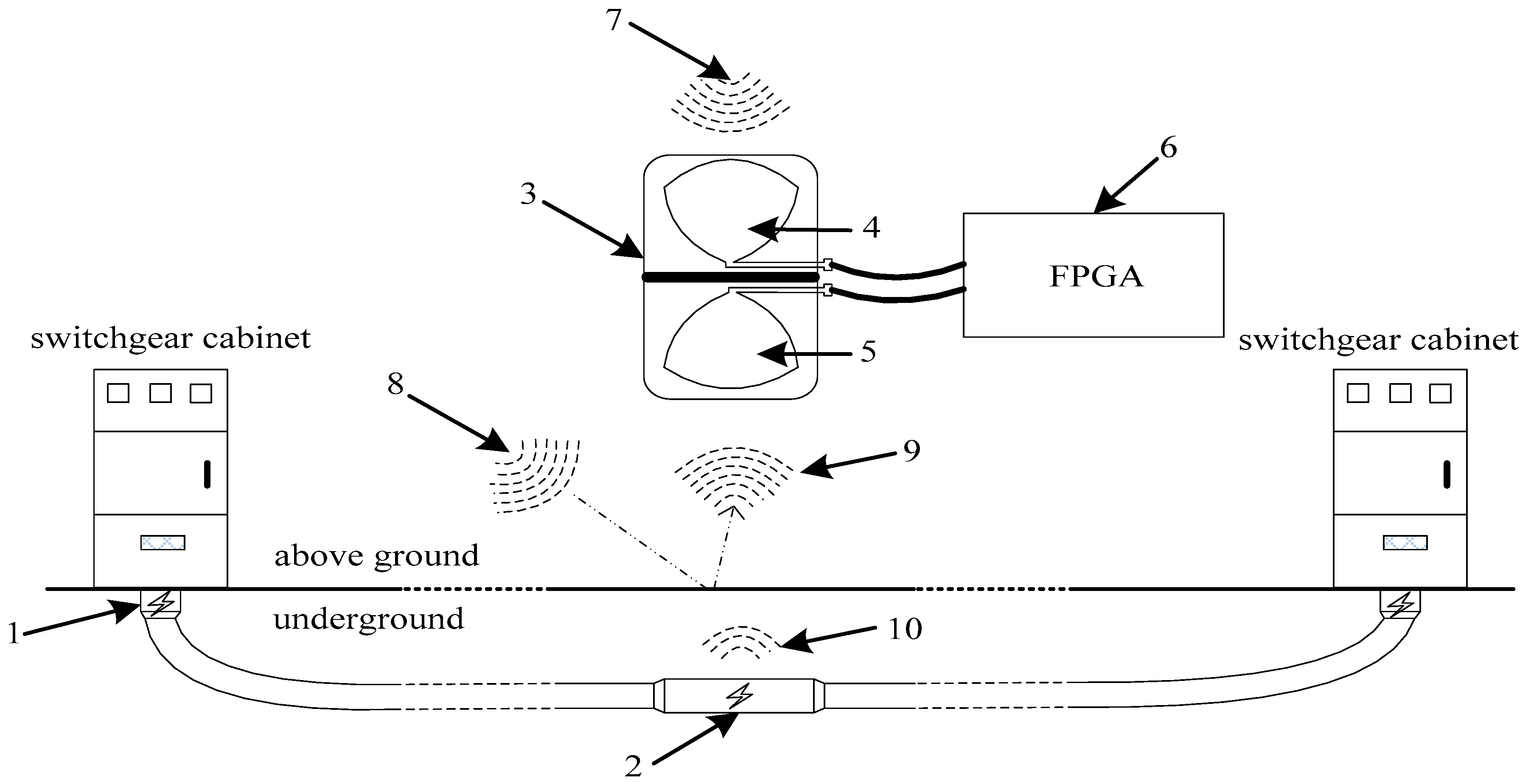
- Antenna Installation Direction Requirements: During on-site installation, the built-in upward directional antenna shall be vertically upward (with a detection angle of 90°) to ensure accurate reception of spatial interference signals. The built-in downward directional antenna shall be vertically downward and aligned directly above the cable joint so as to avoid incomplete reception of partial discharge signals caused by directional deviation.
- ♦
- Mechanical Enclosure and Environmental Adaptability: A waterproof, dustproof and corrosion-resistant sealed enclosure with protection class IP65 is adopted, which is suitable for humid and dusty field environments such as underground cable trenches, tunnels and shafts. The enclosure is made of lightweight aluminum alloy for easy on-site transportation and installation.
- ♦
- On-site Positioning: In cable trenches and tunnels, the antenna shall be installed 20–50 cm directly above the cable joint, away from interference from other power equipment (e.g., switch cabinets, grounding bodies). In shafts, suspension installation can be used to ensure vertical alignment between the antenna and the joint, thus reducing signal obstruction.
- ♦
- Burial depth of 0.5 m: The detection accuracies of metal debris, insulation scratches and conductor burr defects are 97.0%, 96.0% and 95.0%, respectively, with an average accuracy of 96.0%, and the amplitude of the partial discharge signal decreases by about 5% after soil attenuation;
- ♦
- Burial depth of 2.0 m: The detection accuracies of the three defects are 95.0%, 93.0% and 92.0%, respectively, with an average accuracy of 93.3%, and the signal amplitude decreases by about 15%;
- ♦
- Burial depth of 3.0 m: The detection accuracies of the three defects are 92.0%, 90.0% and 89.0%, respectively, with an average accuracy of 90.3%, and the signal amplitude decreases by about 28%. However, after processing by the dynamic multi-notch method, the main profile of the pulse signal can still be effectively extracted without missing detection.
3.2.4. Comparative Verification Experiment of Different Detection Methods
- ♦
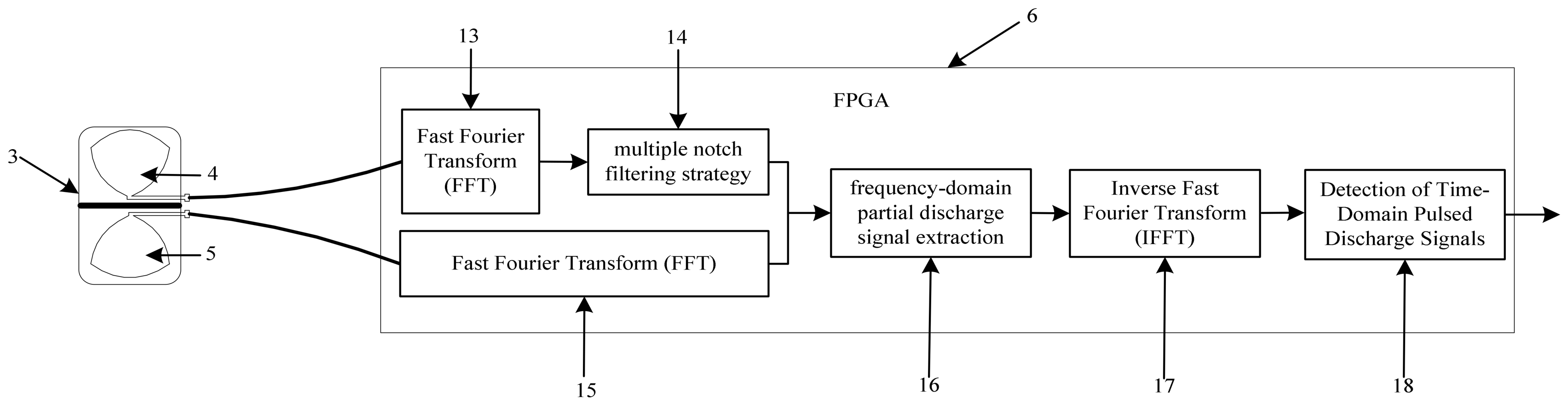
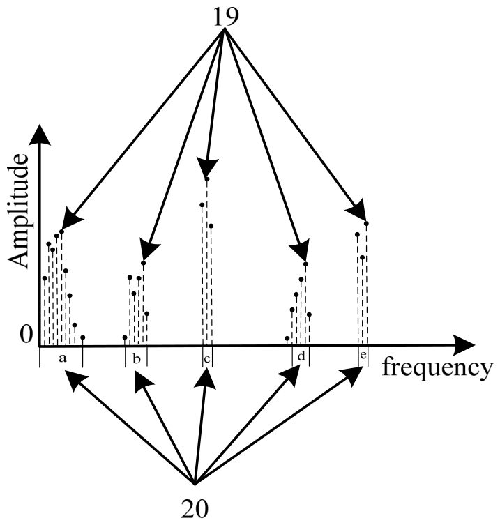
- Dynamic multi-notch method: 2048-point FFT/IFFT transformation is adopted, with a frequency resolution of approximately 2.93 MHz and an effective analysis frequency band of 300 MHz–3 GHz. The step bandwidth of notch filtering is set to 10 MHz, and the interference threshold Q is adaptively set to 3–5 times the background noise. FFT and IFFT are implemented in FPGA with a processing delay of less than 10 ms to ensure real-time performance. The average detection accuracy is ≥92.3% in a normal environment without strong interference and remains 89.5% under strong composite interference.
- ♦
- Fixed notch method: Fixed notch filtering is set at three center frequencies of 500 MHz, 900 MHz, and 1800 MHz. The notch bandwidth of each frequency band is 50 MHz, corresponding to the actual filtering intervals: 500 MHz ± 50 MHz (450 MHz–550 MHz), 900 MHz ± 50 MHz (850 MHz–950 MHz), and 1800 MHz ± 50 MHz (1750 MHz–1850 MHz). The analysis frequency band ranges from 300 MHz to 3 GHz. Three fixed-notch frequency bands of 500 MHz, 900 MHz and 1800 MHz are preset, which cannot track the real-time changes in the on-site interference spectrum and have no filtering effect on interference outside the preset frequency bands, with an average signal extraction success rate of 72.5% and an average detection accuracy of 68.3% in a normal environment.
- ♦
- Traditional UHF detection method: A conventional broadband UHF antenna is adopted, with an operating frequency band of 300 MHz–3 GHz and an antenna gain of 6 dBi. No interference suppression or filtering algorithm is applied. Without any interference suppression measures, the weak partial discharge signal is completely submerged by strong electromagnetic interference, with an average signal extraction success rate of 48.2% and an average detection accuracy of only 45.8% in a normal environment.
- ♦
- Wavelet denoising method: The db4 wavelet basis (suitable for partial discharge pulse signals) is used with five decomposition levels, a soft threshold function, and the sqtwolog threshold rule. Under strong interference conditions, the detection accuracy of the wavelet denoising method is 75.2%, mainly because it is difficult to track dynamically changing interference frequency bands in real time.
- ♦
- Machine learning classification method: The SVM classifier is adopted with an RBF kernel function, penalty coefficient C = 10, and gamma = 0.05. Under strong interference conditions, the detection accuracy of the machine learning classification method is 78.6%, mainly because it requires a large number of samples for training and has poor adaptability to complex on-site interference.

| Detection Method | Average Signal Extraction Success Rate | Average Detection Accuracy in Normal Environment | Detection Accuracy Under Strong Interference |
|---|---|---|---|
| Dynamic multi-notch | 94.7% | ≥92.3% | 89.5% |
| Fixed notch | 72.5% | 68.3% | 52.1% |
| Traditional UHF | 48.2% | 45.8% | 21.3% |
| Wavelet denoising method | 82.7% | 80.6% | 75.2% |
| Machine learning classification method | 85.4% | 83.1% | 78.6% |
4. Conclusions
- The average extraction success rate of the proposed dynamic multi-notch method for weak partial discharge signals reaches 94.7%, and the detection accuracy is ≥92.3% in a normal environment without strong interference, which can effectively extract the weak partial discharge signals of underground cable intermediate joints and solve the problem of poor signal extraction ability of traditional methods.
- This method has excellent anti-interference performance, and the detection accuracy remains 89.5% in a strong composite electromagnetic interference environment (mobile communication + industrial equipment radiation), which is far better than the traditional UHF detection method (45.8%) and the fixed notch method (68.3%) and can adapt to the complex and variable on-site electromagnetic environment.
- This method is suitable for the actual underground engineering scene and can maintain an average detection accuracy of more than 90% within the soil burial depth range of 0.5~3.0 m (a common burial depth for urban underground cables). Even if the signal is attenuated by 80% by the soil, the main profile of the partial discharge pulse signal can still be effectively extracted, meeting the requirements of actual engineering detection.
- This method has excellent anti-misjudgment ability, with a misjudgment rate of only 2.0% under strong electromagnetic interference, which is far lower than the engineering allowable threshold. At the same time, it realizes real-time dynamic suppression of interference with high reliability of detection results, providing a reliable technical solution for the early warning of insulation defects in underground cable intermediate joints.
Author Contributions
Funding
Data Availability Statement
Conflicts of Interest
References
- Pang, B.; Zhu, B.; Wei, X.; Wang, S.; Li, R. On-line Monitoring Method for Long Distance Power Cable Insulation. IEEE Trans. Dielectr. Electr. Insul. 2016, 23, 70–76. [Google Scholar] [CrossRef] [Scilit]
- Zhang, D.; Li, W.; Xiong, X. Overhead Line Preventive Maintenance Strategy Based on Condition Monitoring and System Reliability Assessment. IEEE Trans. Power Syst. 2014, 29, 1839–1846. [Google Scholar] [CrossRef] [Scilit]
- Zhao, X.; Yang, X.; Gao, L.; Li, Q.; Hu, J.; He, J. Tuning the Potential Distribution of AC Cable Terminals by Stress Cone of Nonlinear Conductivity Material. IEEE Trans. Dielectr. Electr. Insul. 2017, 24, 2686–2693. [Google Scholar] [CrossRef] [Scilit]
- Lu, K.K.; Fang, J.; Huang, X.H.; Fang, X.Y. On Prefabricated Stress Cone for HTS Cable Termination. IEEE Trans. Appl. Supercond. 2015, 25, 1–6. [Google Scholar] [CrossRef] [Scilit]
- Gao, Y.S.; Zhao, Q.J.; Yang, L.B.; Chen, Q.; Wu, K.; Zhou, K. Partial Discharge Characteristics of Two Kinds of Knife Scratches on 35 kV Cable Terminals at Room Temperature. Electr. Meas. Instrum. 2017, 54, 71–76. [Google Scholar]
- Renforth, L.A.; Giussani, R.; Mendiola, M.T.; Dodd, L. Online Partial Discharge Insulation Condition Monitoring of Complete High-Voltage Networks. IEEE Trans. Ind. Appl. 2019, 55, 1021–1029. [Google Scholar] [CrossRef] [Scilit]
- Raymond, W.J.K.; Illias, H.A.; Abu Bakar, A.H. High Noise Tolerance Feature Extraction for Partial Discharge Classification in XLPE Cable Joints. IEEE Trans. Dielectr. Electr. Insul. 2017, 24, 66–74. [Google Scholar] [CrossRef] [Scilit]
- Wild, M.; Tenbohlen, S.; Gulski, E.; Jongen, R. Basic Aspects of Partial Discharge On-site Testing of Long Length Transmission Power Cables. IEEE Trans. Dielectr. Electr. Insul. 2017, 24, 1077–1087. [Google Scholar] [CrossRef] [Scilit]
- Driessen, A.B.J.M.; Duivenbode, J.; Wouters, P.A.A.F. Partial Discharge Detection for Characterizing Cable Insulation Under Low and Medium Vacuum Conditions. IEEE Trans. Dielectr. Electr. Insul. 2018, 25, 306–315. [Google Scholar] [CrossRef] [Scilit]
- Liu, C.; Zhang, H.; Xie, Z.; Wang, Z.; Chen, L.; Lin, X.; Ding, H.; Li, Z.; Xiong, W. Combined Forecasting Method of Dissolved Gases Concentration and Its Application in Condition-Based Maintenance. IEEE Trans. Power Deliv. 2019, 34, 1269–1279. [Google Scholar] [CrossRef] [Scilit]
- Gulski, E.; Wester, F.; Smit, J.; Seitz, P.; Turner, M. Advanced partial discharge diagnostic of MV power cable system using Oscillating Wave Test System. IEEE Electr. Insul. Mag. 2000, 16, 17–25. [Google Scholar] [CrossRef] [Scilit]


Disclaimer/Publisher’s Note: The statements, opinions and data contained in all publications are solely those of the individual author(s) and contributor(s) and not of MDPI and/or the editor(s). MDPI and/or the editor(s) disclaim responsibility for any injury to people or property resulting from any ideas, methods, instructions or products referred to in the content. |
© 2026 by the authors. Licensee MDPI, Basel, Switzerland. This article is an open access article distributed under the terms and conditions of the Creative Commons Attribution (CC BY) license.
Share and Cite
Xu, Y.; Zhang, S.; Wu, Y. Research on Partial Discharge Signal Detection Technology of Cable Joints Based on a Dynamic Multi-Notch Method. Energies 2026, 19, 2092. https://doi.org/10.3390/en19092092
Xu Y, Zhang S, Wu Y. Research on Partial Discharge Signal Detection Technology of Cable Joints Based on a Dynamic Multi-Notch Method. Energies. 2026; 19(9):2092. https://doi.org/10.3390/en19092092
Chicago/Turabian StyleXu, Yinghua, Shiping Zhang, and Yongfeng Wu. 2026. "Research on Partial Discharge Signal Detection Technology of Cable Joints Based on a Dynamic Multi-Notch Method" Energies 19, no. 9: 2092. https://doi.org/10.3390/en19092092
APA StyleXu, Y., Zhang, S., & Wu, Y. (2026). Research on Partial Discharge Signal Detection Technology of Cable Joints Based on a Dynamic Multi-Notch Method. Energies, 19(9), 2092. https://doi.org/10.3390/en19092092