


Abstract
To address the problem whereby traditional model predictive control suffers from mismatches between the model and actual parameters due to system parameter variations in the capacitor voltage-balancing control of a neutral-point-clamped (NPC) five-level inverter, an improved model-free predictive control strategy based on particle swarm optimization and the deadbeat principle is proposed. Firstly, an ultra-local model of the inverter is established, and a particle swarm optimization algorithm with an adaptive inertia coefficient is employed to self-tune the control gain of the ultra-local model, thereby reducing current control error. Secondly, the electrical angle of the reference voltage is calculated using the deadbeat principle, and a simplified vector set is constructed for voltage vector traversal. Control is applied only to the capacitor with the largest voltage deviation from the balance value, which reduces computational burden while achieving current tracking and capacitor voltage balancing. Finally, the simulation results show that under steady-state conditions, the output current total harmonic distortion (THD) is 0.28%, and the DC-side capacitor voltage fluctuation is 0.01%, demonstrating a significant improvement in control performance compared with the extremum-seeking control and Kalman filtering methods. Under transient conditions, the proposed control strategy achieves a response time of 0.7 ms while maintaining good control performance and strong robustness. These results verify the effectiveness of the proposed control strategy.
1. Introduction
With the continuous development of high-power converters, neutral-point-clamped (NPC) multilevel inverters have been widely applied in medium- and high-voltage fields such as rail transit due to their advantages of high output voltage quality, low total harmonic distortion (THD) of the current, and relatively simple structure [1,2,3,4]. However, owing to the characteristics of their topology, NPC multilevel inverters suffer from the problem of unbalanced DC-link capacitor voltages. This imbalance can lead to output voltage distortion, increased current THD, and even overvoltage damage to inverter components, thereby severely affecting the performance and reliability of the inverter. Therefore, achieving DC-link capacitor voltage-balancing control for NPC multilevel inverters is of great importance.
At present, the mainstream control methods addressing the DC-link capacitor voltage-balancing problem in NPC multilevel inverters can be broadly classified into two categories: optimized SVPWM strategies and intelligent control algorithms. Optimized SVPWM strategies mainly exploit the effects of different redundant vectors in the space voltage vector diagram on capacitor voltages [5,6], map the multilevel inverter topology to a lower-level structure to increase the number of available redundant vectors [7], or employ virtual voltage vectors [8], thereby achieving capacitor voltage-balancing control. However, in general, optimized SVPWM strategies in multilevel inverters suffer from issues such as high computational complexity, cumbersome vector selection, and relatively high switching frequency. These drawbacks limit their application in practical engineering and may also affect inverter efficiency [9]. Intelligent control algorithms currently mainly include finite-control-set model predictive control (FCS-MPC) and model-free predictive control (MFPC). ① FCS-MPC exploits the finite number of switching states of the inverter by enumerating all possible switching combinations and using the system model to predict the future behavior of the system. The switching state that minimizes the evaluation function is then selected online as the control output for the next sampling instant. Owing to its fast dynamic response, its capability for straightforward multi-objective control, and the absence of a modulation stage [10,11], FCS-MPC has been widely studied, and existing improvements mainly focus on reducing current harmonics and suppressing common-mode voltage [12,13,14], both of which have achieved promising results. However, FCS-MPC relies heavily on accurate system parameters, and in practical applications, discrepancies often exist between the model parameters and the actual system parameters, and the latter may vary with operating conditions and environmental changes. These factors can cause the actual system output to deviate from the given reference value [15], and degrade the system’s output performance [16]. ② MFPC employs a predictive control principle similar to that of FCS-MPC; however, it adopts a highly simplified black-box model that integrates the actual system inputs and outputs. This approach effectively mitigates adverse effects caused by parameter mismatch and enhances the robustness and applicability of the predictive control strategy. Among these methods, the MFPC algorithm based on the ultra-local model replaces the system model with a differential equation over a very short time scale. Compared with other model-free predictive control methods, it offers advantages such as a simple structure and reduced data requirements for computation, and it has been widely applied in the field of motor control [17,18,19].
However, the application of ultra-local model-based MFPC to multilevel inverters still faces two challenges. First, the exhaustive traversal of all output voltage vectors (e.g., 125 vectors for a five-level inverter) imposes a heavy computational burden [20]. To mitigate this, several simplified vector selection schemes have been proposed, such as rectangular region classification [21] and artificial neural networks [22]. Nevertheless, these methods still involve nontrivial computational overhead during the simplification process. Second, the control gain α in the ultra-local model is typically set as the reciprocal of the load inductance. Consequently, the control performance of the conventional ultra-local model is adversely impacted by significant changes in the inductance parameter [23]. In addition, recent studies indicate that the optimal α deviates from this nominal value, and it significantly affects both the current THD and the prediction error. Therefore, determining the optimal α is crucial for reducing current control error and harmonic distortion, yet this issue has received limited attention in the literature. Existing approaches, such as extremum-seeking control [24] and Kalman filtering [25], can tune α online but may introduce disturbances or increase system uncertainty. To address the above issues, this paper builds upon the existing research foundation of MFPC based on the ultra-local model and proposes an improved MFPC strategy that integrates the particle swarm optimization (PSO) algorithm with the deadbeat control principle to achieve capacitor voltage-balancing control in an NPC five-level inverter. The main contributions of this paper are shown below.
- A parameter-independent ultra-local modeling framework with adaptive gain self-tuning is proposed. Unlike existing MFPC methods that treat the control gain heuristically or introduce external disturbances via extremum-seeking or Kalman filtering, this work use an adaptive inertia-weight PSO algorithm. The proposed method minimizes current tracking error without injecting additional perturbations into the control loop, achieving both high accuracy and disturbance-free operation.
- A deadbeat-principle-based simplified-vector-set construction method is developed to reduce computational complexity while preserving control precision. In contrast to existing vector simplification techniques that rely on rectangular region classification or artificial neural networks—which still entail considerable computational overhead—the proposed approach analytically derives the reference voltage angle using the deadbeat principle and constructs a reduced vector set containing only 35 vectors (down from 125) without heuristic sector partitioning. This yields a 3× reduction in computation time per cycle while maintaining full current tracking capability.
- A targeted capacitor voltage-balancing strategy is introduced that controls only the most unbalanced capacitor. Unlike conventional methods that attempt to regulate all DC-link capacitors simultaneously or rely on redundant vector allocation across multiple levels, the proposed scheme identifies the capacitor with the maximum voltage deviation and selectively applies control actions. Leveraging the inherent voltage constraint among series-connected capacitors, this approach significantly simplifies the balancing control logic while ensuring global voltage equalization, without increasing the evaluation function’s dimensionality.
- Comprehensive simulation-based validation under both steady-state and dynamic conditions is provided, including motor load scenarios. Beyond standard resistive–inductive load tests, the proposed PSO-MFPC strategy is rigorously evaluated under abrupt reference current changes, sudden load variations, different sampling frequencies (2 kHz, 5 kHz, 10 kHz), and induction motor drive conditions. Quantitative comparisons against ESC- and KF-based tuning methods demonstrate that the proposed approach achieves the lowest THD (0.28% in steady state) and the smallest capacitor voltage fluctuation (0.01%), establishing its superiority over existing tuning techniques.
2. Overall Strategy for Capacitor Voltage-Balancing Control in a Five-Level NPC Inverter
2.1. Basic Principle of Capacitor Voltage-Balancing Control
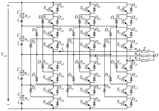
The topology of the NPC five-level inverter is shown in Figure 1. Here, denotes the input voltage on the DC side of the inverter; , , , and represent the DC-side capacitors; ~ are the anti-parallel diodes; ~ are the clamping diodes; and the load is a three-phase load. Each phase leg contains eight power switching devices ~ (x = a, b, c, representing phases a, b, and c of the inverter, respectively). The conduction states of these switching devices determine the switching state of the corresponding phase leg, and different switching states result in different phase output voltages. When a power switching device is turned on, its corresponding switching state is defined as “1”; when the device is turned off, the switching state is defined as “0”. The mapping relationship between the switching states of the three-phase inverter legs and the corresponding output phase voltages is shown in Table 1 [26].
Figure 1.
Topology diagram of the NPC five-level inverter.
Table 1.
Mapping table between the switching states of power devices and the output phase voltage in an NPC five-level inverter.
When the inverter outputs different switching states, the DC-side branch currents are influenced by the three-phase output currents. This interaction causes current to flow through the DC-side capacitor branches, resulting in varying degrees of charging and discharging of the capacitors and consequently leading to capacitor voltage imbalance. The relationship between the three-phase output current of the inverter and the DC-side capacitor current can be expressed by Equation (1) [27]:
In this expression, sgn denotes the sign function defined as shown in Equation (2):
Equation (1) reveals a nonlinear relationship between the switching states and the capacitor currents, as the sign function introduces discontinuous behavior. Consequently, the capacitor voltage dynamics makes the balancing control a nontrivial dynamic system problem.
2.2. Capacitor Voltage-Balancing Control Strategy Based on Improved MFPC
Due to the existence of 53 = 125 output voltage vectors in the NPC five-level inverter, directly traversing all 125 vectors would result in a substantial computational burden and consequently degrade control performance. Meanwhile, determining the control gain of the ultra-local model remains a key challenge in its application.
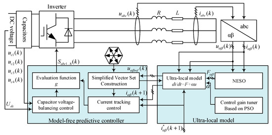
As shown in the overall control system structure in Figure 2, the improved MFPC strategy mainly consists of two components: the ultra-local model and the model-free predictive controller. The corresponding control procedure is as follows: (1) establish the ultra-local model of the NPC five-level inverter, estimate the lumped disturbance of the ultra-local model using a nonlinear extended state observer (NESO), and tune the control gain of the ultra-local model using the PSO algorithm; (2) calculate the required reference voltage based on the deadbeat principle, determine the angle of the reference voltage, and select appropriate voltage vectors to construct a simplified vector set; (3) traverse the voltage vectors within the simplified vector set, compute the evaluation function that incorporates both current tracking control and capacitor voltage-balancing control, and select the voltage vector corresponding to the minimum evaluation function for output.
Figure 2.
Overall control system structure of the NPC five-level inverter.
3. Design of an Ultra-Local Model Considering Parameter Self-Tuning
3.1. Construction of the Ultra-Local Model
The ultra-local model, originally introduced by Fliess and Join [28], provides a data-driven framework for control design without requiring detailed system parameters. This model has since been widely adopted and further developed in power electronics and motor drive applications, as reviewed in [29,30]. A typical single-input single-output (SISO) ultra-local model is expressed as shown in Equation (3):
In this expression, and denote the input and output of the system, respectively; represents the control gain of the ultra-local model; and denotes the lumped disturbance that needs to be observed.
According to (3), the ultra-local model of the inverter can be formulated as (4).
Here, takes the values and , representing the corresponding parameters in the inverter αβ coordinate system; is the control gain of the ultra-local model; denotes the inverter output voltage; denotes the inverter output current; and represents the lumped disturbance of the system, including load parameter variations and system measurement errors.
3.2. Design of the Lumped Disturbance Observer
The NESO replaces the feedback gains of the system state variables with a nonlinear fal function. This design achieves an approximate filtering effect while avoiding the time-delay introduced by conventional filters in the system [31]. The NESO is specifically designed to estimate the lumped disturbance in real time without requiring an accurate system model. Its nonlinear structure (via the fal function) enables effective handling of system nonlinearities and time-varying dynamics, which are inherent in the NPC five-level inverter under parameter variations or load changes. Therefore, this study adopts the NESO to observe the lumped disturbance of the ultra-local model. The corresponding state equation is given in Equation (5).
In the equation, denotes the observed value of the inverter output current, represents the observation signal of the current error, and is the observed value of the lumped disturbance . and are the specified NESO output error correction gains. The function fal is designed as the nonlinear function defined below.
In the equation, and are given constants.
3.3. Control Gain Tuning Based on the PSO Algorithm
The control gain in the ultra-local model must be carefully selected. If is too small, the system’s adjustment to the input will be insufficient, making it difficult to compensate for disturbances in the system. This may result in a sluggish control response or require larger input variations to achieve the desired output. Conversely, if is too large, the system may become overly sensitive to control inputs, which can easily lead to overshoot, oscillations, or instability. Therefore, the selection of the control gain plays a crucial role in ultra-local model control systems. To address this issue, this paper proposes a self-tuning scheme for α using a PSO algorithm with an adaptive inertia coefficient. Unlike conventional PSO, the proposed method dynamically adjusts the inertia weight based on particle fitness, thereby avoiding local optima and improving convergence. The core innovation lies in integrating this adaptive PSO into the ultra-local model-based MFPC framework to minimize current tracking error without introducing external disturbances. Due to the nonlinear nature of the inverter system, the optimal control gain of the ultra-local model cannot be determined analytically. Therefore, the PSO algorithm with an adaptive inertia coefficient is employed to search for the optimal gain in real time, ensuring robust performance under dynamic operating conditions.
The standard PSO algorithm models each candidate solution as a particle with position and velocity. The velocity and position are updated by:
To balance global and local search, a nonlinear dynamic inertia coefficient is adopted [32]:
where the inertia weight decreases when fitness values are dispersed (enhancing local search) and increases when they converge (enhancing global search). This adaptive mechanism is critical for preventing the optimization of α from getting trapped in suboptimal regions.
To achieve effective current-tracking performance, such that the error between the output current and the reference current is minimized, the fitness function designed in this study is given in Equation (9), where denotes the number of inverter sampling instances.
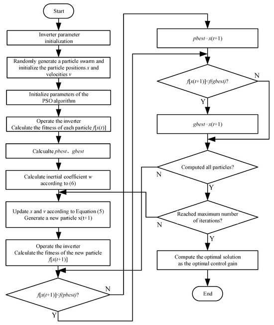
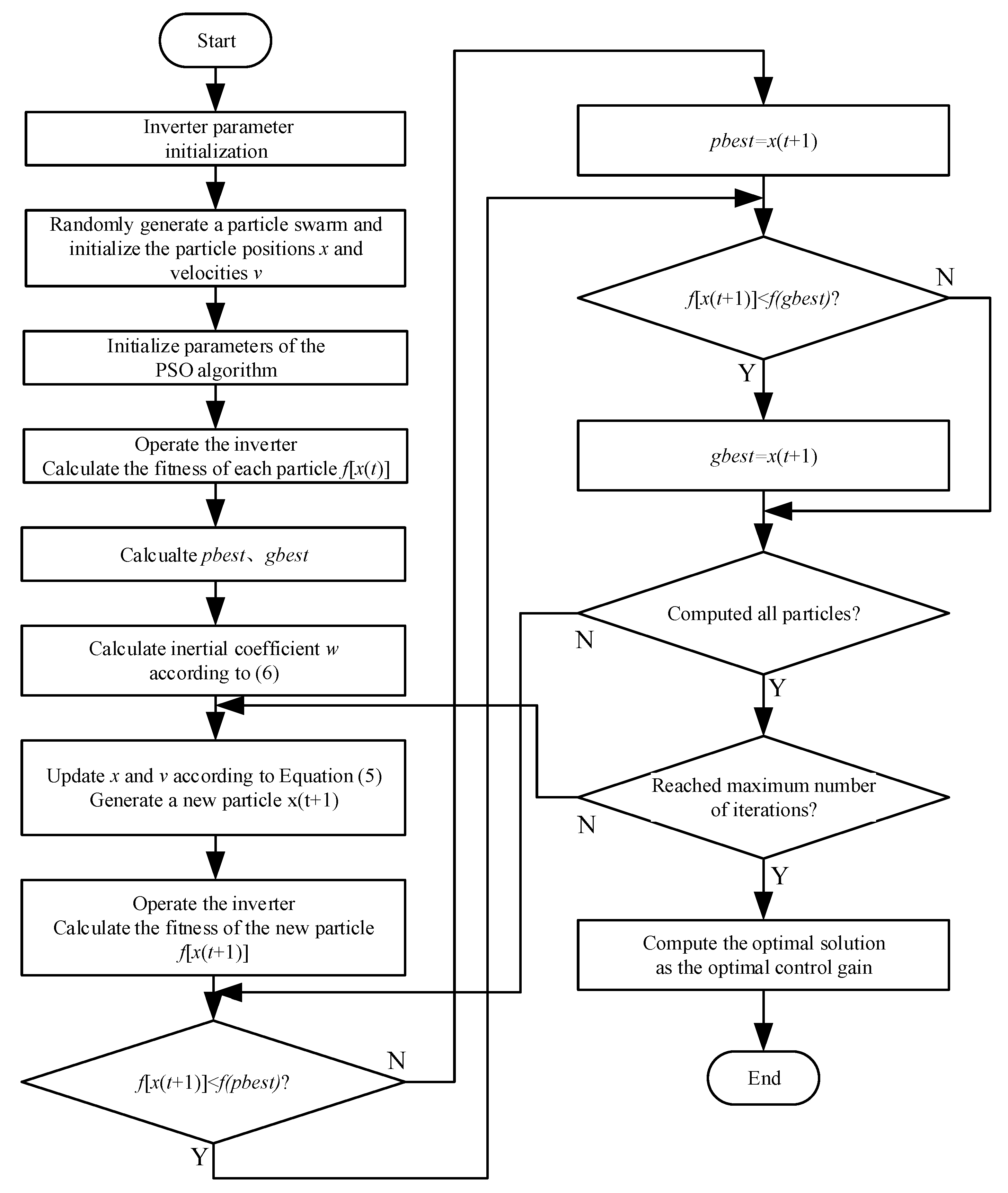
The overall tuning procedure is illustrated in Figure 3. The key difference from existing PSO-based tuning methods is that the proposed approach operates online without injecting external perturbations, preserving the model-free nature of the controller.
Figure 3.
Flowchart of the PSO algorithm-based control gain tuning process.
As shown in the figure above, after the inverter system is initialized, a particle swarm is randomly generated to represent the control gains of the ultra-local model. The corresponding current control error is calculated as the fitness function value of each particle. The individual best and global best positions are then determined, followed by updating the velocity and position of each particle and recalculating the fitness value after the update. If the updated fitness value is better than the previous individual best value, it is set as the new individual best. If the individual best is superior to the previous global best, it is updated as the new global best. When the number of iterations reaches the preset maximum, the optimal solution is output; otherwise, the iteration process continues.
4. Model-Free Predictive Controller Design
4.1. Current Tracking Control
One of the objectives that MFPC must achieve is current tracking control, ensuring that the three-phase output currents of the inverter can effectively follow the three-phase reference currents. To this end, it is first necessary to discretize the ultra-local model shown in Equation (4), so as to obtain the currents at the next sampling instant when the inverter outputs different voltage vectors. Therefore, the forward difference method is employed to discretize the model. Let the system sampling period be , the resulting discretized ultra-local model of the NPC five-level inverter is as follows:
In the equation, denotes the observed value of the lumped disturbance of the ultra-local model obtained through NESO observation. Based on this discretized ultra-local model, the predicted value of the output current at the next sampling instant can be obtained.
Subsequently, the reference current at the next instant must be determined. Under simplified treatment, since the sampling period is extremely short, the three-phase reference currents can be assumed to remain constant within one sampling period, i.e., . However, this simplified approach introduces a one-sampling-period tracking delay in the three-phase current tracking process. This paper employs the Lagrange extrapolation method to compensate for the delay in the reference current, and the current reference value at time can be obtained as follows:
For three-phase sinusoidal signals, is typically selected. In this study, is chosen. Accordingly, the calculation formula for the current reference value at time is given as:
After determining the reference current for the next sampling instant, all output voltage vectors of the inverter are traversed. The voltage vector that minimizes the deviation between the predicted output current of the inverter at the next instant and the reference current is selected, thereby achieving current tracking control of the inverter.
4.2. Capacitor Voltage-Balancing Control
Another objective that MFPC must achieve is capacitor voltage-balancing control, ensuring that the capacitor voltages on the DC side of the inverter remain balanced. For a five-level NPC inverter, the balanced voltage value of each DC-side capacitor is . Let denote the difference between the capacitor voltage and the balanced value:
- (1)
- When , that is, the capacitor voltage is lower than the balanced value, if , the current charges the capacitor, causing to increase and move toward the balanced value; conversely, if , the current discharges the capacitor, causing to decrease and further deviate from the balanced value.
- (2)
- When , that is, the capacitor voltage is higher than the balanced value, if , the current discharges the capacitor, causing to decrease and move toward the balanced value; conversely, if , the current charges the capacitor, causing to increase and further deviate from the balanced value.
In summary, it can be determined that when is satisfied, the capacitor voltage moves toward the balanced value; when is satisfied, the capacitor voltage deviates from the balanced value. Therefore, in capacitor voltage-balancing control, it is only necessary to determine the capacitor with the largest deviation from the balanced value, i.e., the capacitor with the maximum value of . Then, an appropriate voltage vector is selected so that the corresponding of that capacitor is minimized, thereby achieving voltage-balancing control for that capacitor. Furthermore, due to the relationship among the DC-side capacitor voltages of the inverter, the voltages of the remaining capacitors will automatically tend to shift toward the balanced value under this constraint, thereby realizing overall capacitor voltage balancing. This method only requires the calculation of the voltage of a single capacitor, which greatly simplifies the computational process.
4.3. MFPC Evaluation Function Determination
The MFPC strategy proposed in this paper aims to minimize the difference between the inverter output current and the reference value in current tracking control [33]. Considering control objectives, control accuracy, and computational burden, the squared difference between the predicted output current and the reference value is selected as the basic form of the evaluation function for current tracking control. For capacitor voltage-balancing control, it is only necessary to minimize corresponding to the capacitor with the largest imbalance relative to the balanced value, thereby achieving DC-side capacitor voltage balancing of the inverter.
This study involves two control variables: current tracking and capacitor voltage balancing. MFPC can incorporate multiple control variables into the evaluation function and regulate them simultaneously. Furthermore, because the importance and physical characteristics of each control variable may differ, weighting coefficients can be introduced for adjustment, providing considerable flexibility. Since the evaluation function in this study includes both current tracking and capacitor voltage balancing, although they are equally important in inverter control, their physical characteristics differ and their magnitudes in the evaluation function may not be on the same scale. Therefore, weighting coefficients must be introduced into the evaluation function [34] and properly tuned to balance and compensate for the different physical characteristics of each variable, while also enhancing the flexibility of model-free predictive control in multi-objective regulation. Accordingly, the evaluation function for the MFPC can be designed as follows:
In the expression, and denote the inverter current reference values at time obtained from Equation (12); and denote the predicted values of the inverter output current at time obtained from Equation (10); denotes the difference between the voltage of the DC-side capacitor with the largest offset balancing degree and the corresponding balanced value obtained from Equation (13); denotes the current of that capacitor calculated from Equation (1); and denotes the weighting coefficient.
4.4. Simplified-Vector-Set Construction
Both conventional MPC and MFPC require traversal of all 125 voltage vectors for the NPC five-level inverter, which significantly increases the computational burden of the control system. The deadbeat principle is a continuous prediction algorithm that determines, in real time, the input required to satisfy the control objective, thereby enabling the state variables to track the reference value without error within a single control period. Therefore, by using the deadbeat principle to calculate the reference voltage for the next sampling instant, and then determining which nearby voltage vectors can be utilized based on the position of this reference voltage in the vector diagram, a simplified vector set can be constructed. This approach reduces the computational complexity associated with exhaustive vector traversal.
According to the ultra-local model and the deadbeat principle, the reference voltage required to produce the specified reference current at the output can be calculated as follows:
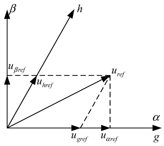
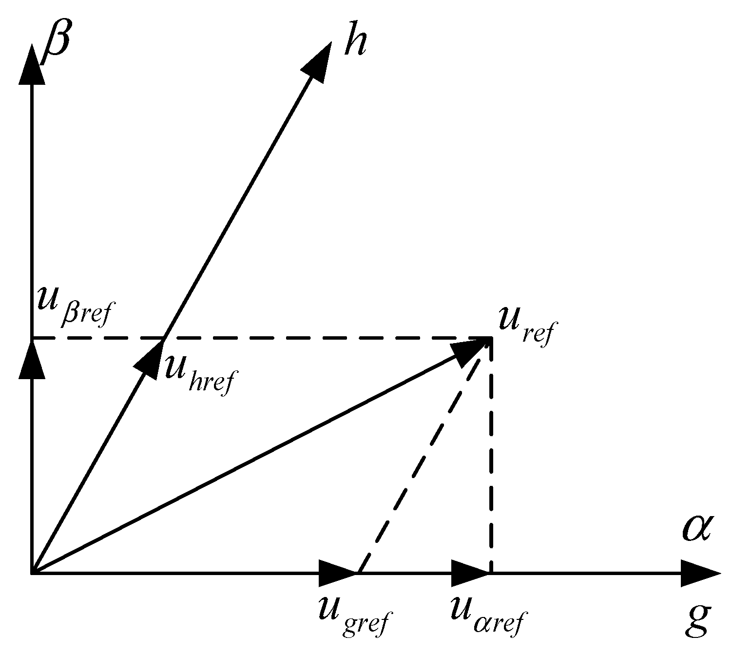
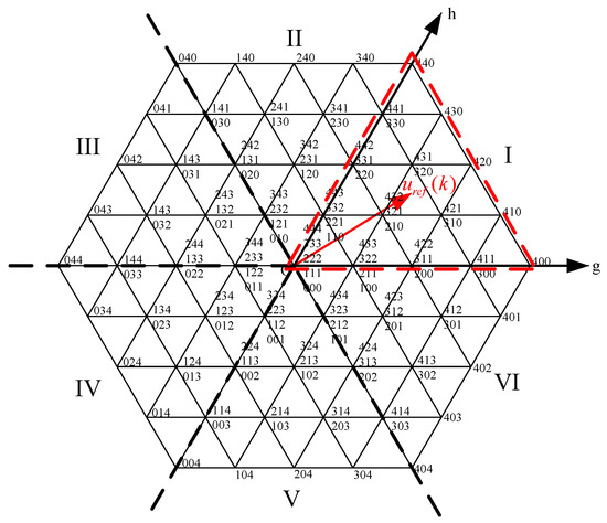
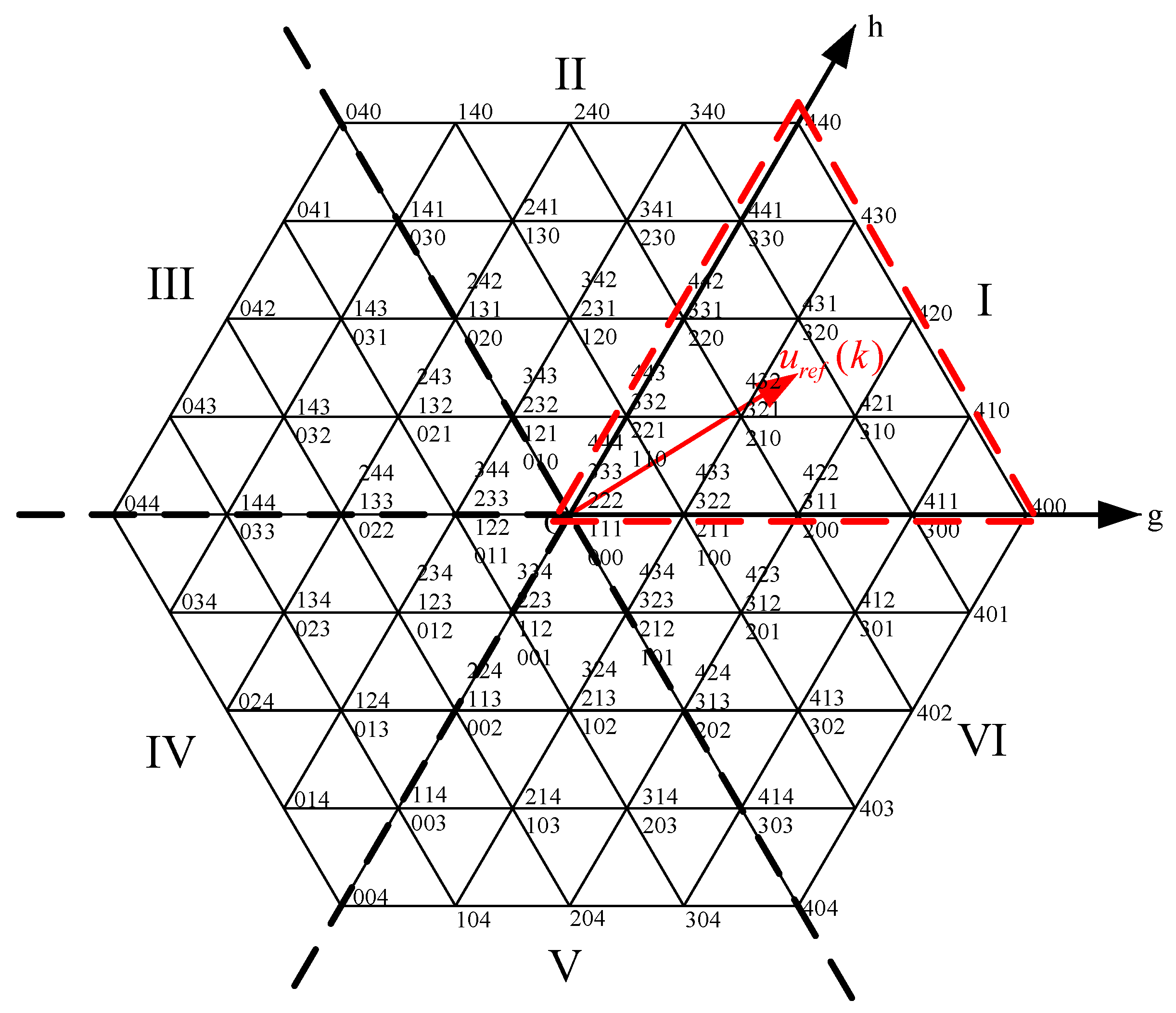
Thus, the coordinates of the reference voltage required to produce the specified reference current in the αβ coordinate system can be obtained, allowing its position to be determined. However, directly identifying the small sector in which the reference voltage lies may lead to two issues. First, under a high modulation index, that is, in the outer region of the output voltage vector diagram, the number of available redundant vectors is significantly reduced, making it impossible to achieve capacitor voltage balancing using redundant vectors. Second, due to the uncertainty of the observed value of the ultra-local model lumped disturbance , the calculated reference voltage may not fall within any small sector, making it impossible to determine the redundant vectors for traversal. Therefore, this paper adopts a 60° coordinate system and determines only the large sector in which the reference voltage vector is located. The vectors corresponding to that large sector are then selected to construct a simplified vector set for traversal, thereby reducing computational complexity. In the 60° coordinate system, the g-axis coincides with the α-axis of the 90° coordinate system, and the h-axis is obtained by rotating the α-axis counterclockwise by 60° about the coordinate origin. The relationship between the 60° coordinate system and the αβ coordinate system is shown in Figure 4.
Figure 4.
Correspondence between the 60° coordinate system and the αβ coordinate system.
The reference voltage vectors and are transformed into the coordinates and in the 60° coordinate system, as shown in Equation (16):
Subsequently, the magnitude relationships among , , and 0 are evaluated to determine the large sector in which the reference voltage vector is located, as illustrated in Figure 5. The simplified vector set is then constructed using the voltage vectors corresponding to that large sector. During the subsequent model-free predictive control traversal process, only the voltage vectors within this simplified vector set need to be examined, thereby accelerating the computational speed of the system. The specific correspondence between large sectors is presented in Table 2 [35]. For example, if the reference voltage vector falls within large sector I as shown in Figure 5, the voltage vectors associated with large sector I are used for traversal. According to the space vector diagram of the NPC five-level inverter, each simplified vector set constructed in this manner contains only 35 voltage vectors; compared with the original 125 voltage vectors, this approach effectively reduces the computational time required.
Figure 5.
Large sector division and schematic diagram of the reference voltage vector.
Table 2.
Sector division table of the major large sector in which the reference voltage vector is located in the 60° coordinate system.
To verify the effectiveness of the simplified traversal vector set strategy proposed in this paper in reducing computational time, a simulation comparison was conducted in the Simulink environment. The proposed strategy was compared with the conventional approach that traverses all 125 output voltage vectors, as well as with the strategies based on rectangular region classification and artificial neural networks proposed in [21,22]. The comparison results are presented in Table 3. The results show that the simplified traversal vector set strategy proposed in this paper achieves the shortest computation time per iteration, indicating that the strategy can effectively reduce computational complexity.
Table 3.
Comparison of the time required for one computation cycle under different control strategies.
4.5. Overall Workflow of the Improved MFPC Algorithm
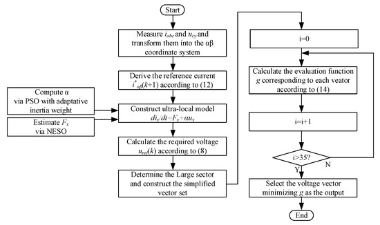
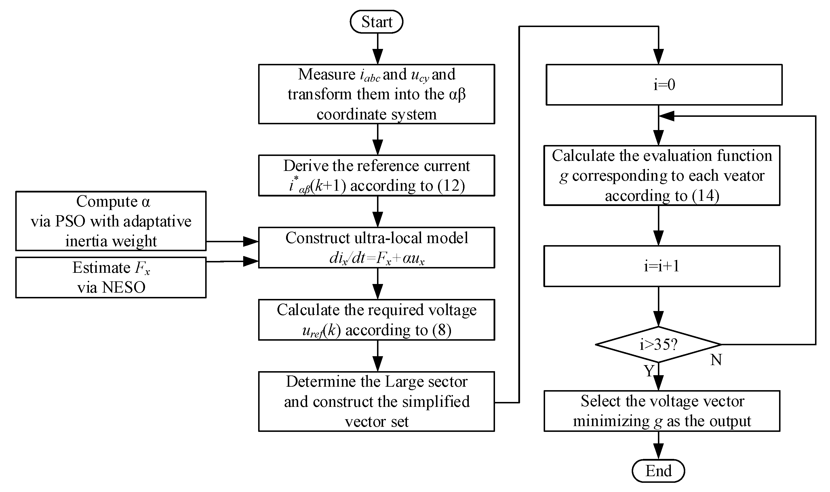
Based on the above analysis, once the observed value of the lumped disturbance in the ultra-local model, the optimal control gain, and the simplified vector set are obtained, the improved MFPC for the NPC five-level inverter based on the ultra-local model can be implemented. Accordingly, a flowchart of the proposed improved MFPC is shown in Figure 6.
Figure 6.
Improved MFPC flowchart.
The main control procedure is as follows:
- (1)
- Sample the three-phase currents of the inverter at the current instant , , and the DC-side capacitor voltages , , , , and obtain the controlled variables in the αβ coordinate system and through the Clark transformation.
- (2)
- Derive the reference values of the three-phase output currents at the next instant, , , according to (12).
- (3)
- Calculate the required voltage , according to (15). Then, use the 60° coordinate system to determine the large sector in which the reference voltage is located, and select the corresponding output voltage vectors of that sector to construct a simplified vector set.
- (4)
- According to (10) and (1), calculate the predicted value of the output current at the next instant and corresponding to each voltage vector in the simplified vector set, as well as the current corresponding to the capacitor with the largest voltage deviation from the balance point.
- (5)
- Compute the evaluation function according to (13), and select the voltage vector that minimizes for output, thereby achieving current tracking control and voltage-balancing control of the DC-side capacitors of the NPC five-level inverter.
During the process, the lumped disturbance of the ultra-local model is observed online through the NESO, and the control gain is tuned using the PSO algorithm with an adaptative inertia coefficient.
5. Simulation Verification
To verify the effectiveness of the proposed improved MFPC (hereinafter referred to as PSO-MFPC) control strategy, a corresponding model was established in MATLAB R2024a/Simulink. The algorithm was evaluated through simulation from two aspects: current tracking performance and capacitor voltage-balancing performance.
The system simulation parameters were referenced from the actual parameters of a specific Shanghai Metro train model, and a resistive–inductive load simulation model was designed accordingly. The DC input voltage of the inverter is , the DC-side capacitance is , the load resistance is , and the load inductance is . The sampling frequency of the control strategy is 10,000 Hz. In the PSO algorithm, the initial population size is , the maximum number of iterations is , the learning factors are , the maximum inertia coefficient is , and the minimum inertia coefficient is .
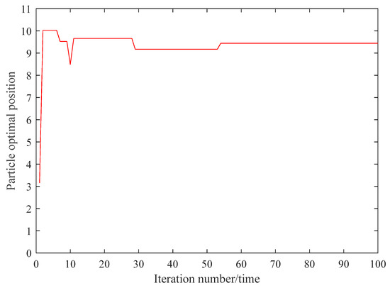
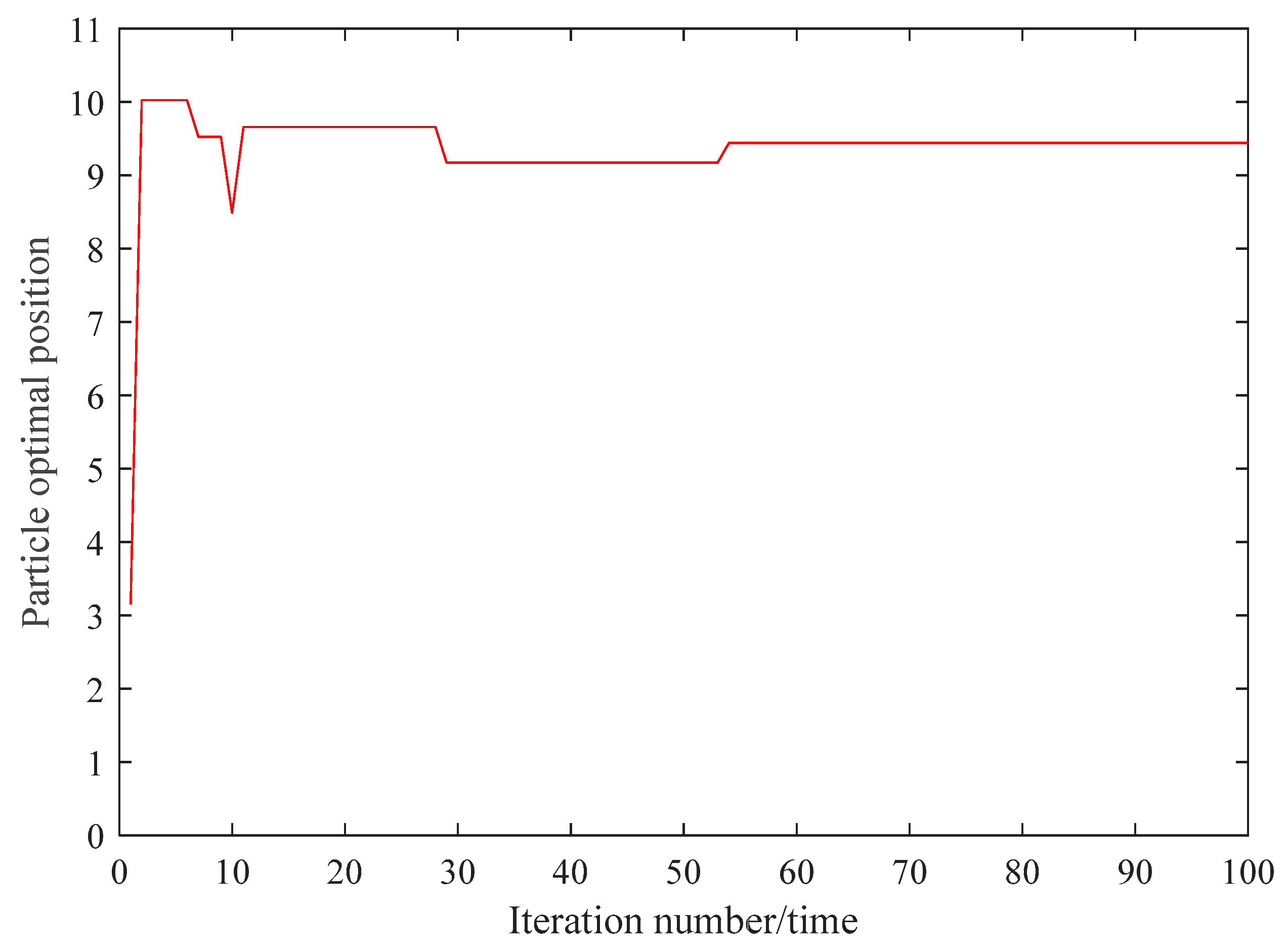
The proposed adaptive inertia-weight PSO algorithm exhibits satisfactory convergence characteristics in tuning the control gain α of the ultra-local model. As illustrated in Figure 7, the fitness value, defined as the current tracking error, decreases rapidly within the first 10 iterations and stabilizes after approximately 15 iterations. The optimal control gain converges to 9.44 and remains stable thereafter, indicating that the algorithm does not suffer from premature convergence or significant oscillation. The adaptive inertia coefficient, which increases when fitness values tend to be consistent and decreases when they are dispersed, effectively balances global exploration and local exploitation during the iterative process. This mechanism prevents the algorithm from getting trapped in local optima and ensures convergence to a near-global optimum within a limited number of iterations.
Figure 7.
The convergence characteristics of the PSO algorithm.
Subsequently, the PSO-MFPC method is compared with the control gain tuning approaches based on extremum-seeking control (ESC) and Kalman filtering (KF) proposed in references [22] and [23], respectively, to verify the effectiveness of the proposed method.
5.1. Steady-State Control Performance
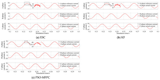
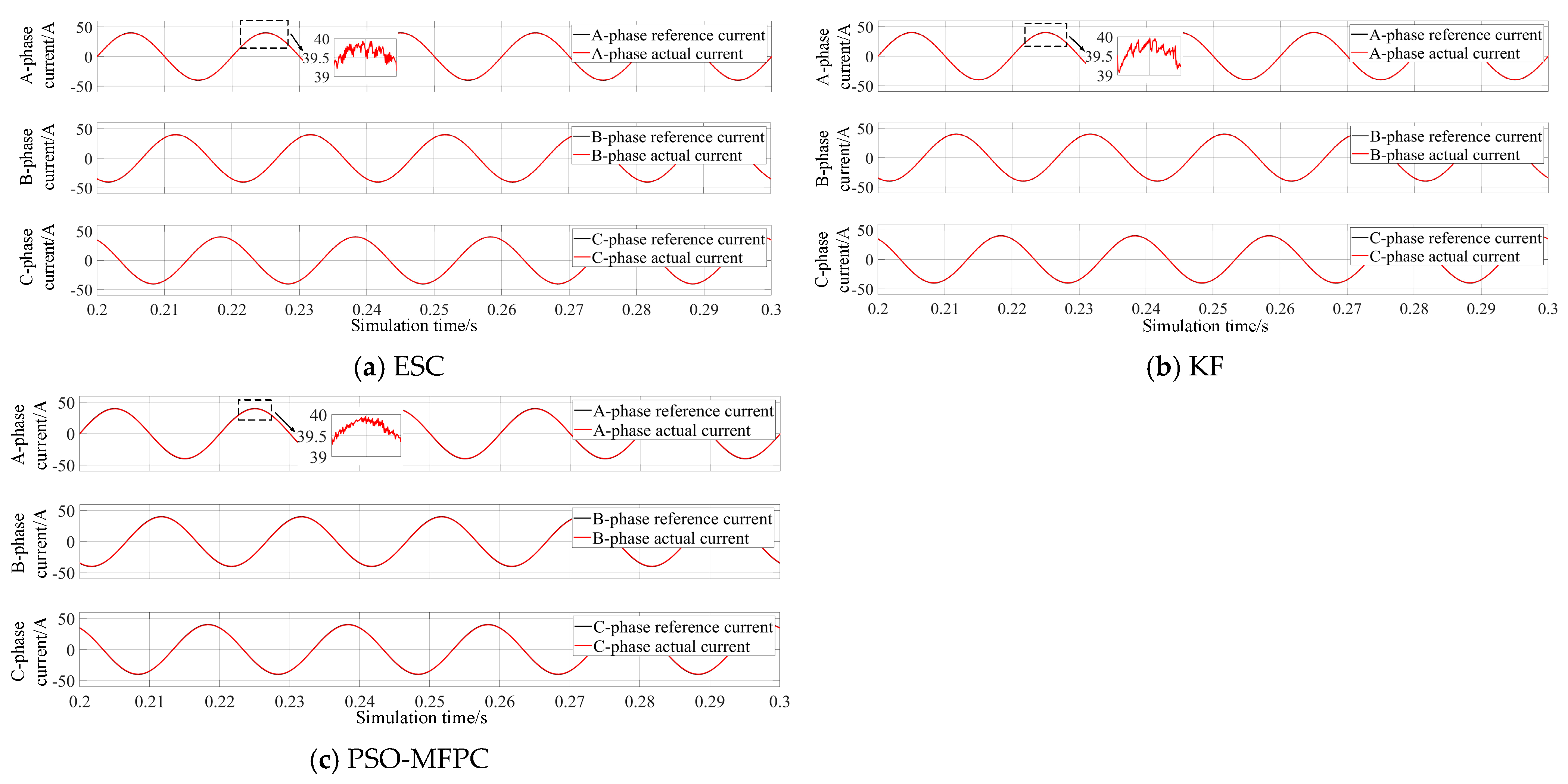
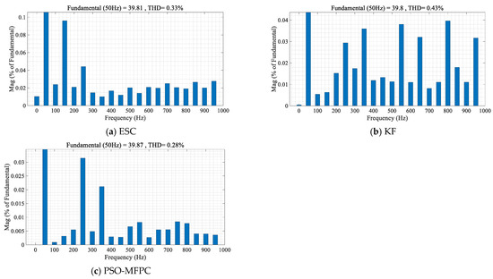
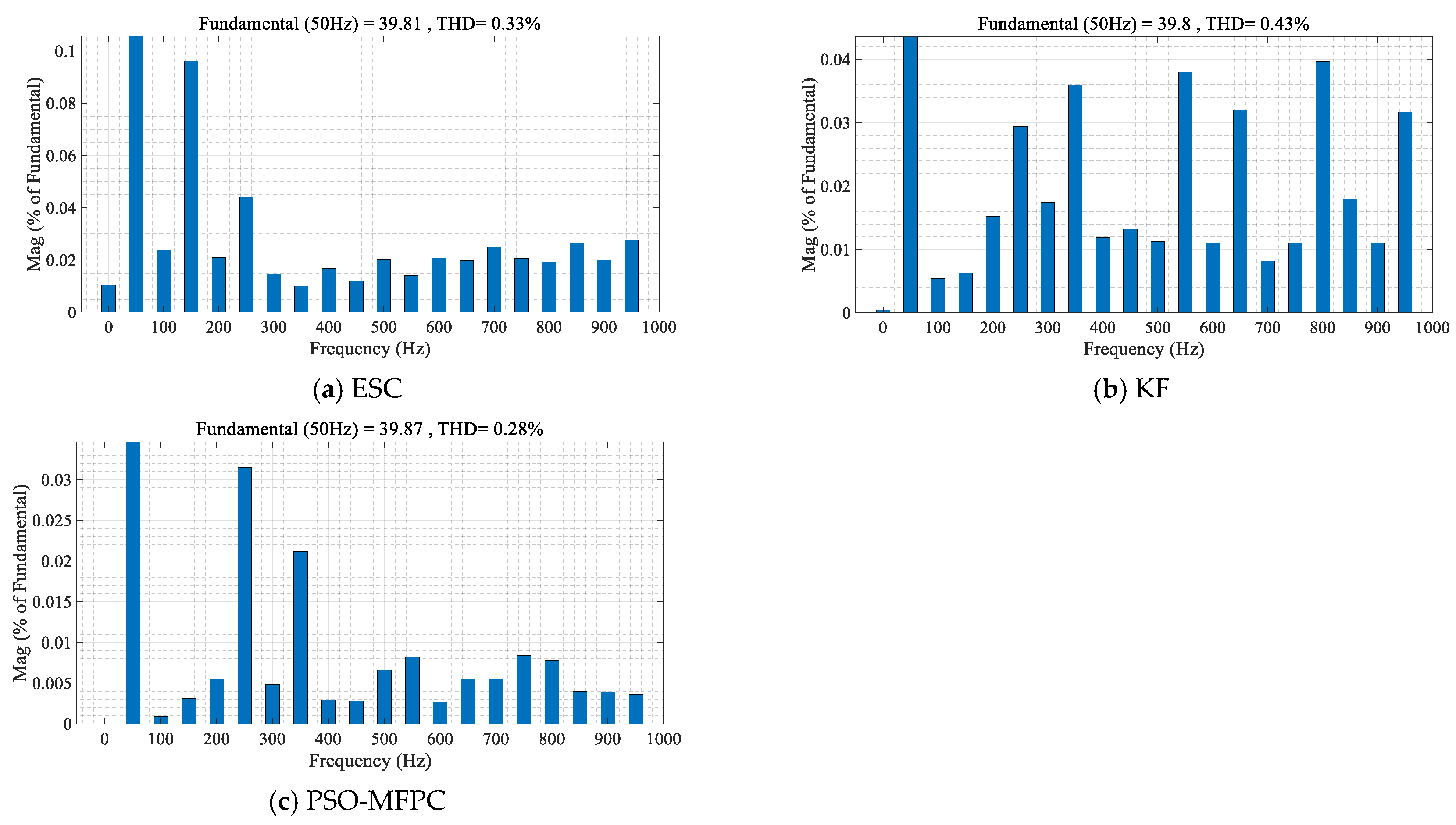
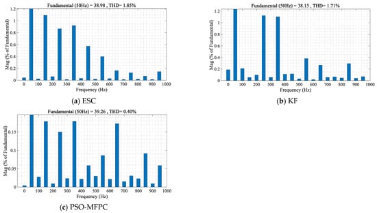
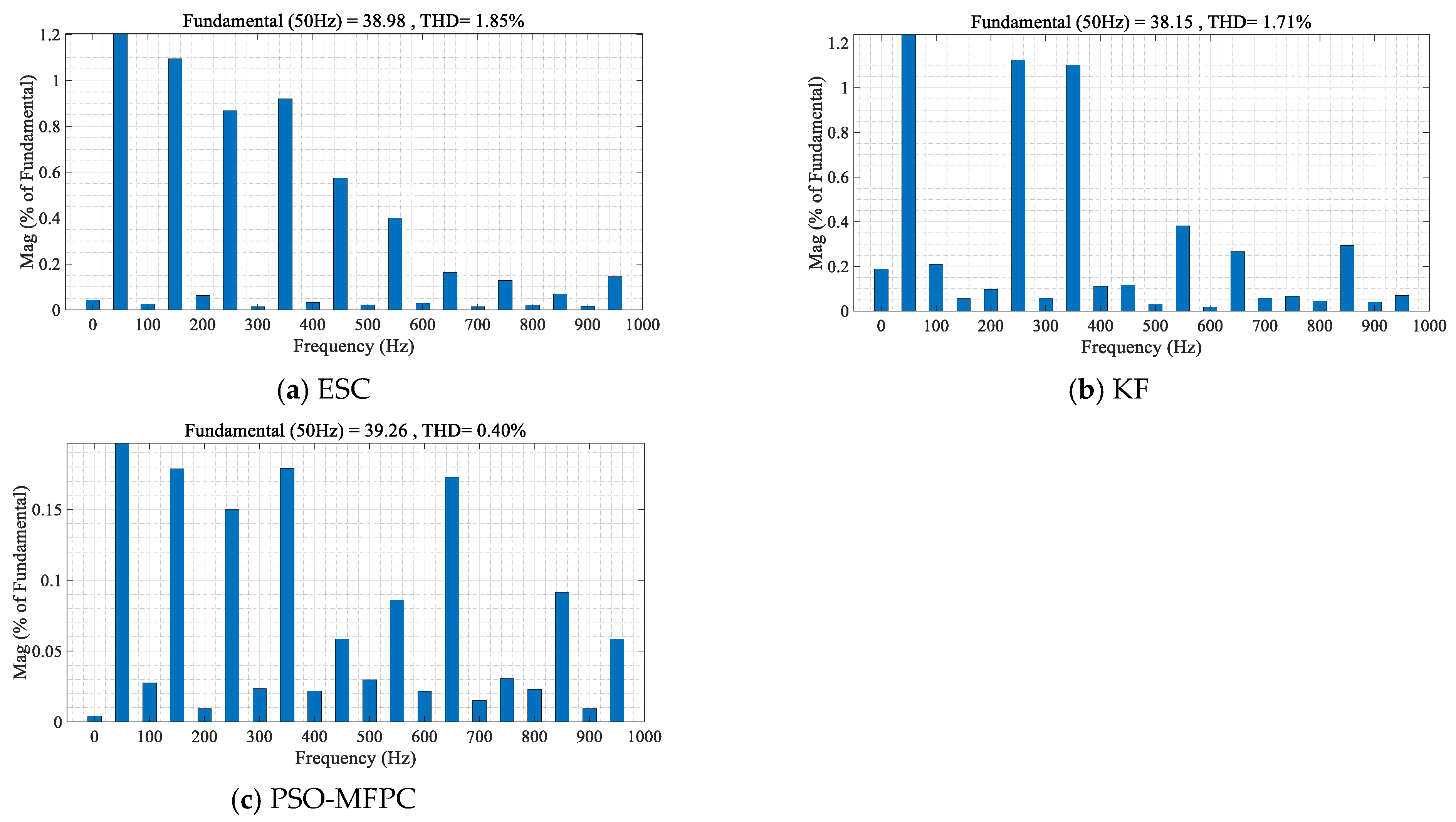
Assuming the reference current amplitude is 40 A with a frequency of 50 Hz, the system is controlled using ESC, KF, and PSO-MFPC. The corresponding three-phase output current waveforms and current spectra are shown in Figure 8 and Figure 9. As illustrated in Figure 8 and Figure 9, all three algorithms enable the inverter’s three-phase output currents to effectively track the reference current; however, the proposed PSO-MFPC algorithm achieves the smallest current fluctuation. FFT analysis indicates that the output current amplitudes of the three methods are 39.81 A, 39.80 A, and 39.87 A, respectively, while the corresponding THD values are 0.33%, 0.43%, and 0.28%. The calculated fluctuation rates are 1.00%, 0.06%, and 0.005%, respectively. These results demonstrate that the proposed PSO-MFPC algorithm provides the best current tracking performance and output current quality.
Figure 8.
Steady-state output current waveform.
Figure 9.
Steady-state load current THD spectrum.
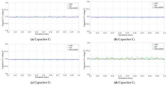
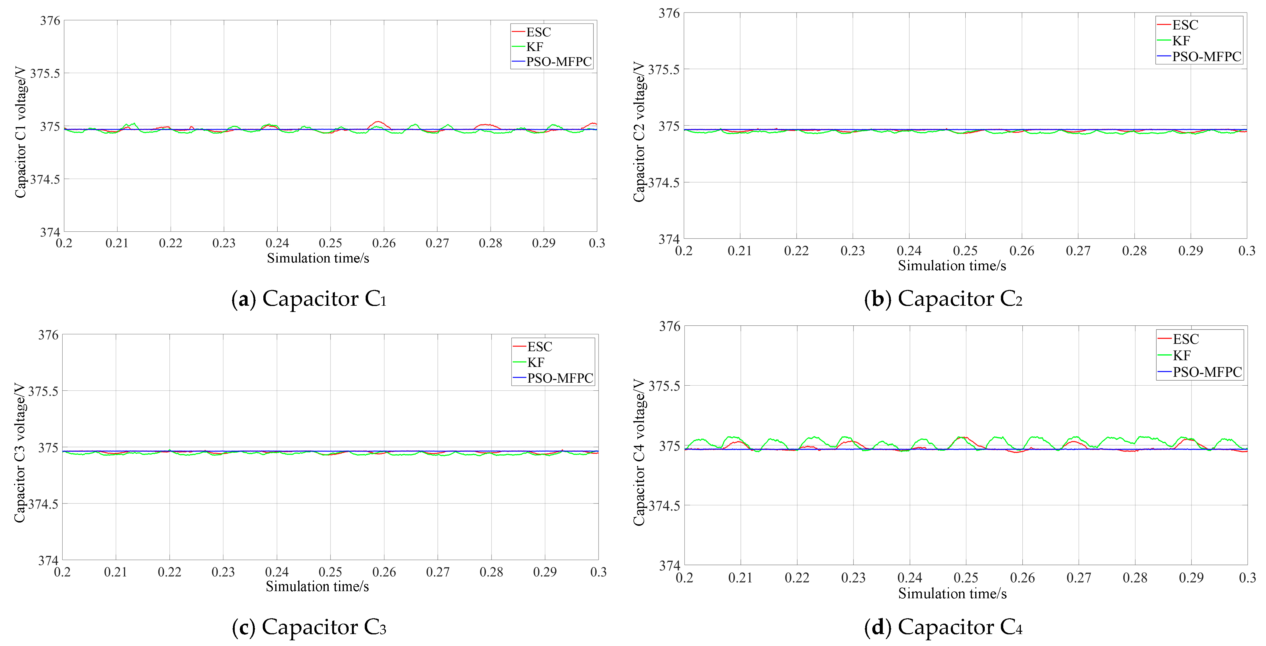
Figure 10 shows the waveform of the DC-side capacitor voltage. As observed in the figure, all three control strategies are capable of maintaining the DC-side capacitor voltage at the balanced value of 375 V. However, further observation indicates that the PSO-MFPC strategy produces the smallest voltage fluctuation. The voltage fluctuation rates of the three control strategies are 0.53%, 0.48%, and 0.01%, respectively, demonstrating that the PSO-MFPC control strategy proposed in this study achieves the most effective DC-side capacitor voltage-balancing performance.
Figure 10.
Steady-state DC-side capacitor voltage waveform.
It can be observed that the output current under the proposed PSO-MFPC algorithm can effectively track the reference current, while the DC-side capacitor voltages are maintained with the best satisfactory balancing performance. Under these conditions, the THD is lower than that obtained with ESC and KF methods. This indicates that the proposed PSO-MFPC strategy can effectively regulate the inverter output current to track the reference current while ensuring improved current quality, and simultaneously achieve balanced control of the DC-side capacitor voltages.
5.2. Transient Control Performance
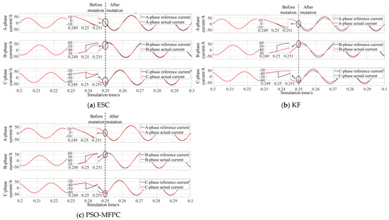
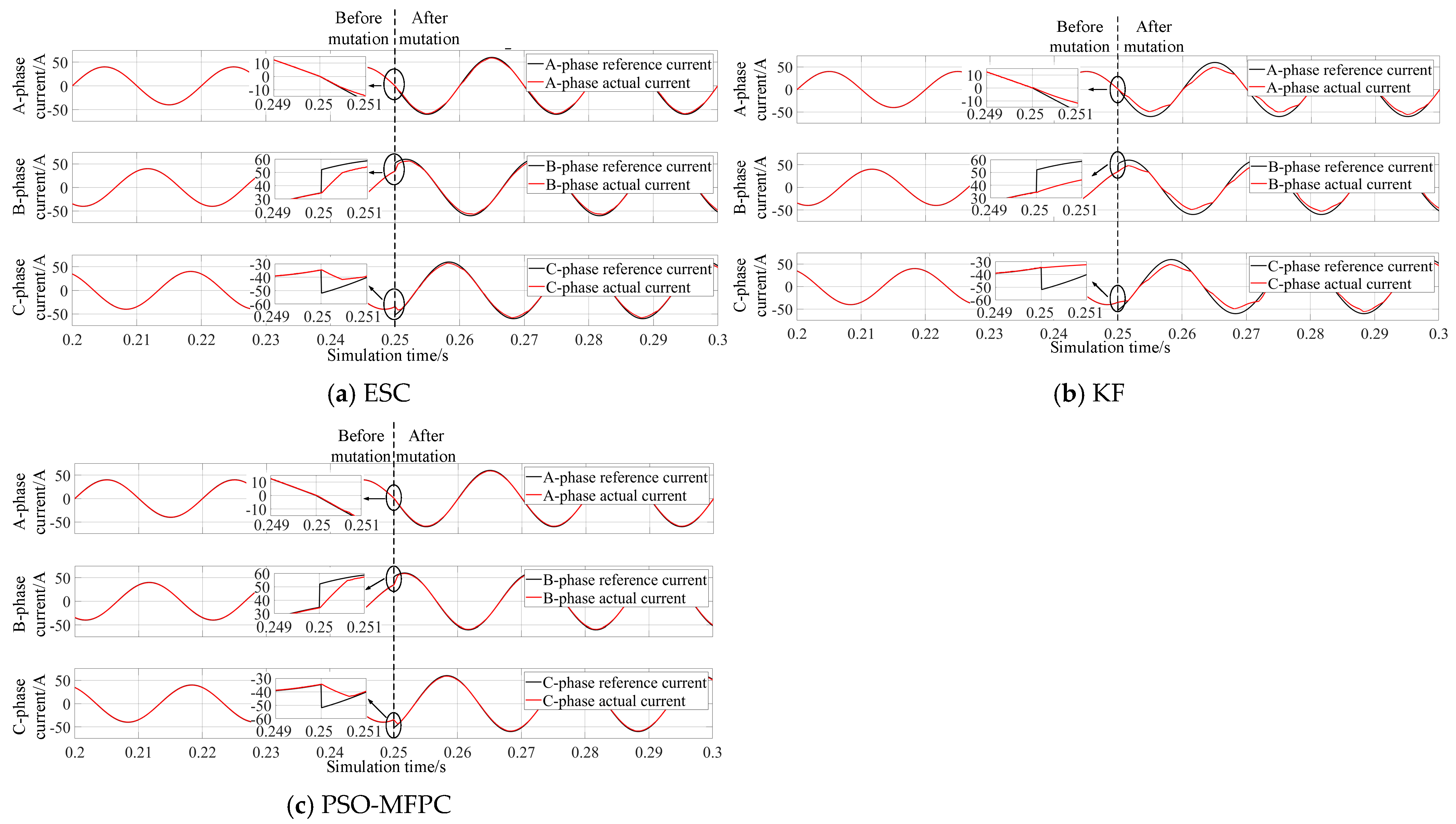
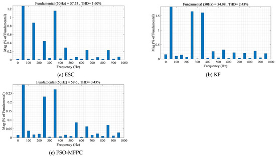
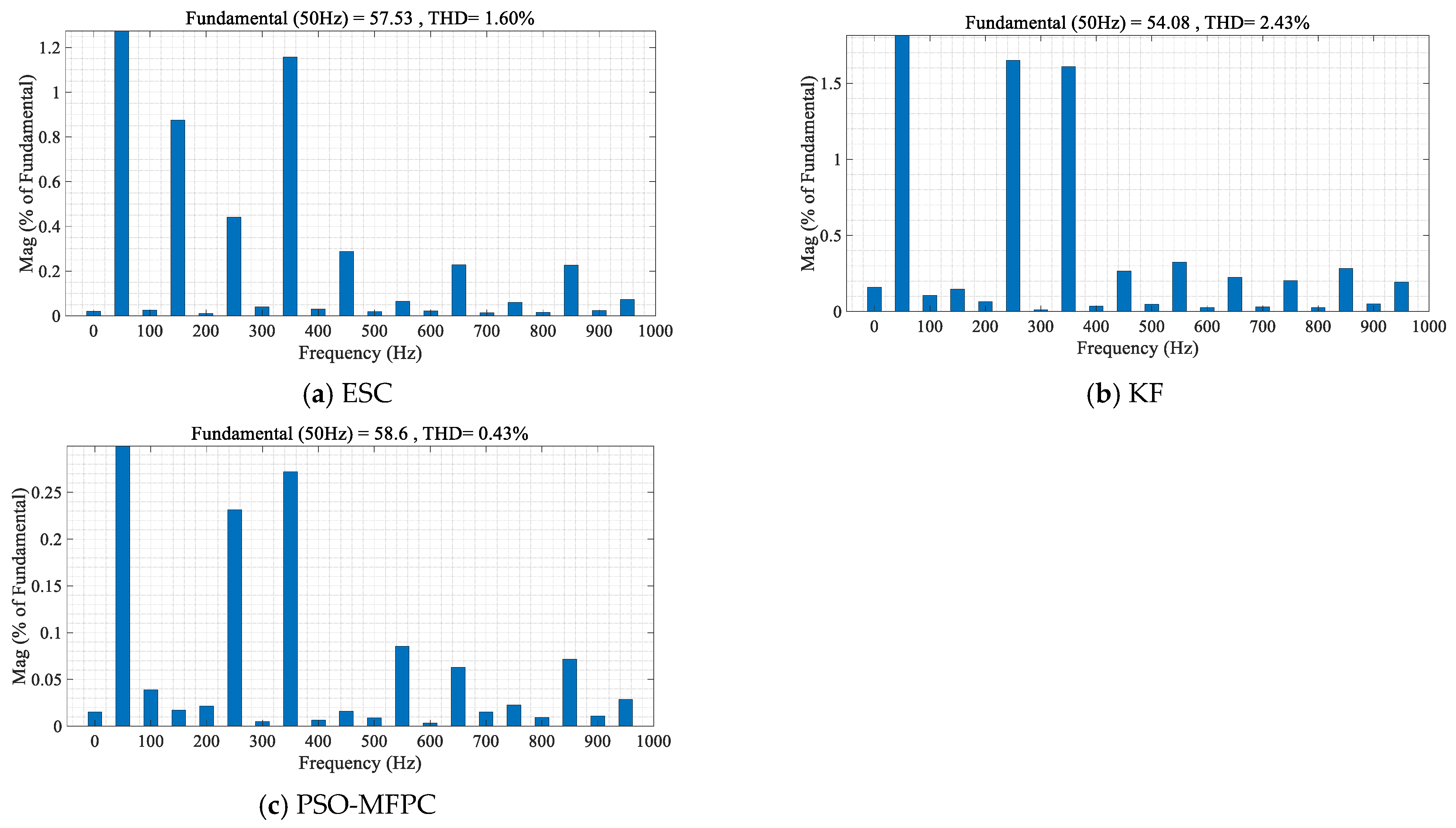
To verify the robustness of the proposed algorithm, simulations were conducted under two conditions: sudden changes in the reference current and sudden load variations. First, the amplitude of the reference current was set to change abruptly from 40 A to 60 A at 0.25 s. The corresponding current waveforms and spectra are shown in Figure 11 and Figure 12. According to the FFT analysis, the current amplitudes after the step change under the three control strategies are 57.53 A, 54.08 A, and 58.59 A, with THD values of 1.60%, 2.43%, and 0.44%, respectively. At the same time, the dynamic response time of the system is only 0.7 ms. These results indicate that the proposed PSO-MFPC algorithm can ensure that the three-phase output current of the inverter effectively tracks the reference current after the sudden change, while maintaining high output current quality. Despite the abrupt change, which introduces a strong nonlinear disturbance, the proposed PSO-MFPC algorithm maintains current tracking with minimal overshoot and the fastest settling time among the three methods.
Figure 11.
Output current waveform under conditions of a sudden change in the reference current.
Figure 12.
THD spectrum of the output current under conditions of a sudden change in the reference current.
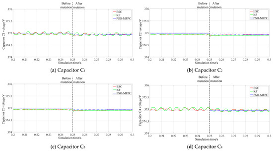
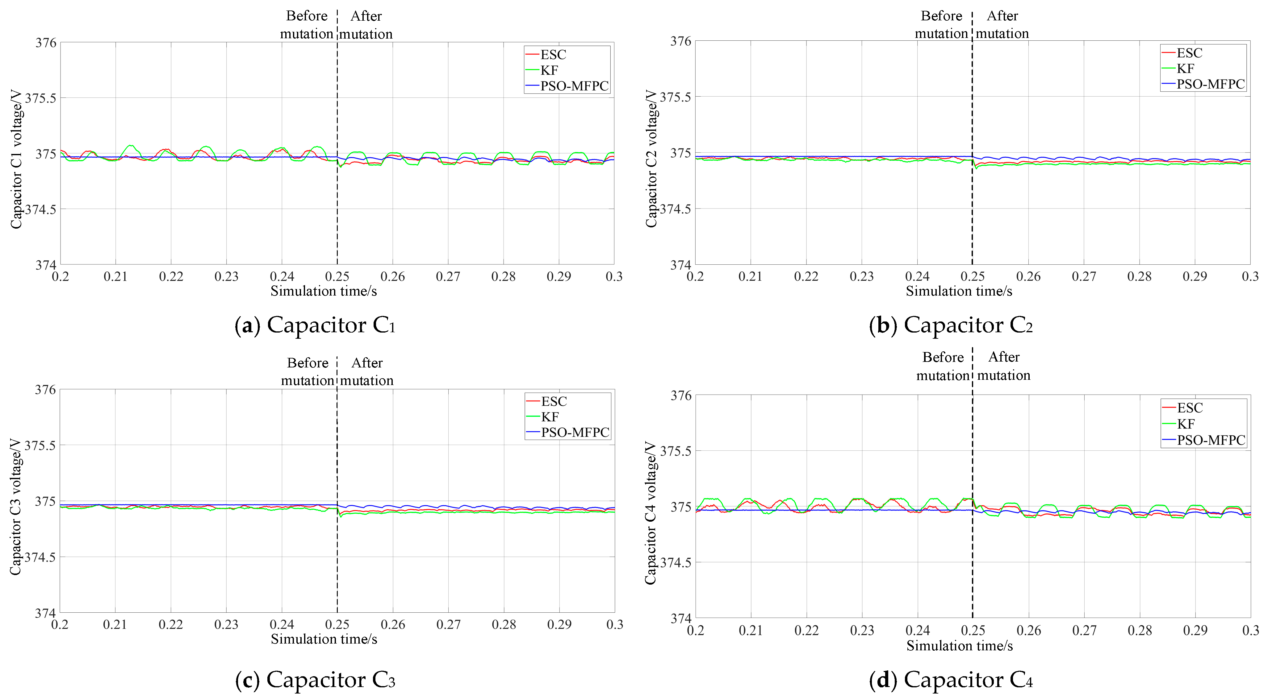
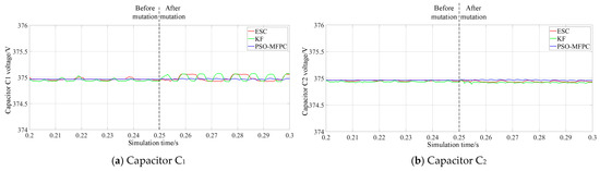
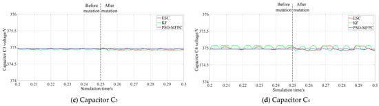
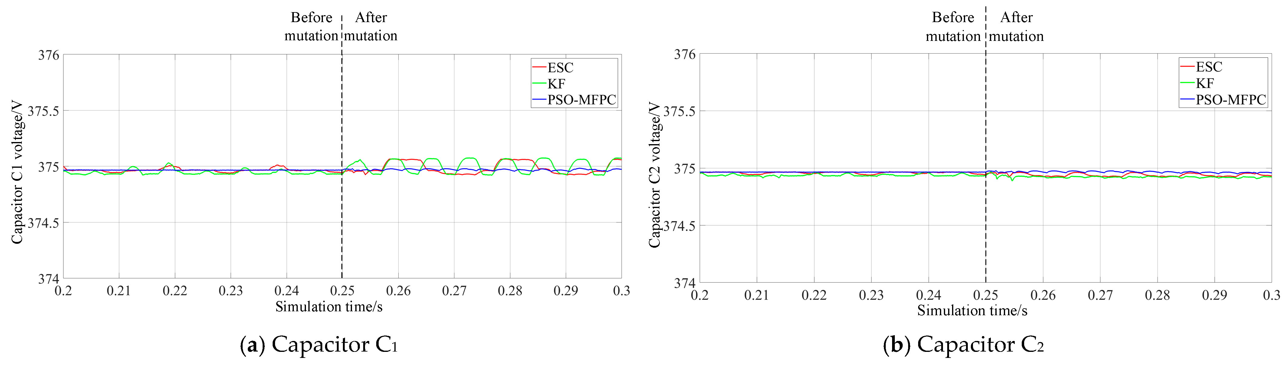
Figure 13 shows the DC-side capacitor voltage waveforms under three control strategies before and after a sudden change in the reference current. It can be observed that the voltage fluctuation rates of the three control strategies are 0.013%, 0.025%, and 0.003%, respectively. These results indicate that the proposed control strategy can effectively achieve voltage balancing of the DC-side capacitors while exhibiting the smallest voltage fluctuation.
Figure 13.
DC-side capacitor voltage waveform under conditions of a sudden change in the reference current.
From the simulation results above, it can be observed that when a sudden change occurs in the reference current amplitude, and the DC-side capacitor voltage balance can still be maintained, the PSO-MFPC proposed in this paper can ensure that the inverter output current continues to track the reference current well even when the reference current changes abruptly, while also maintaining high output current quality with the minimum THD.
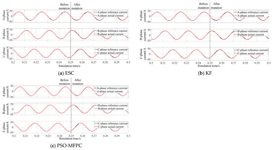
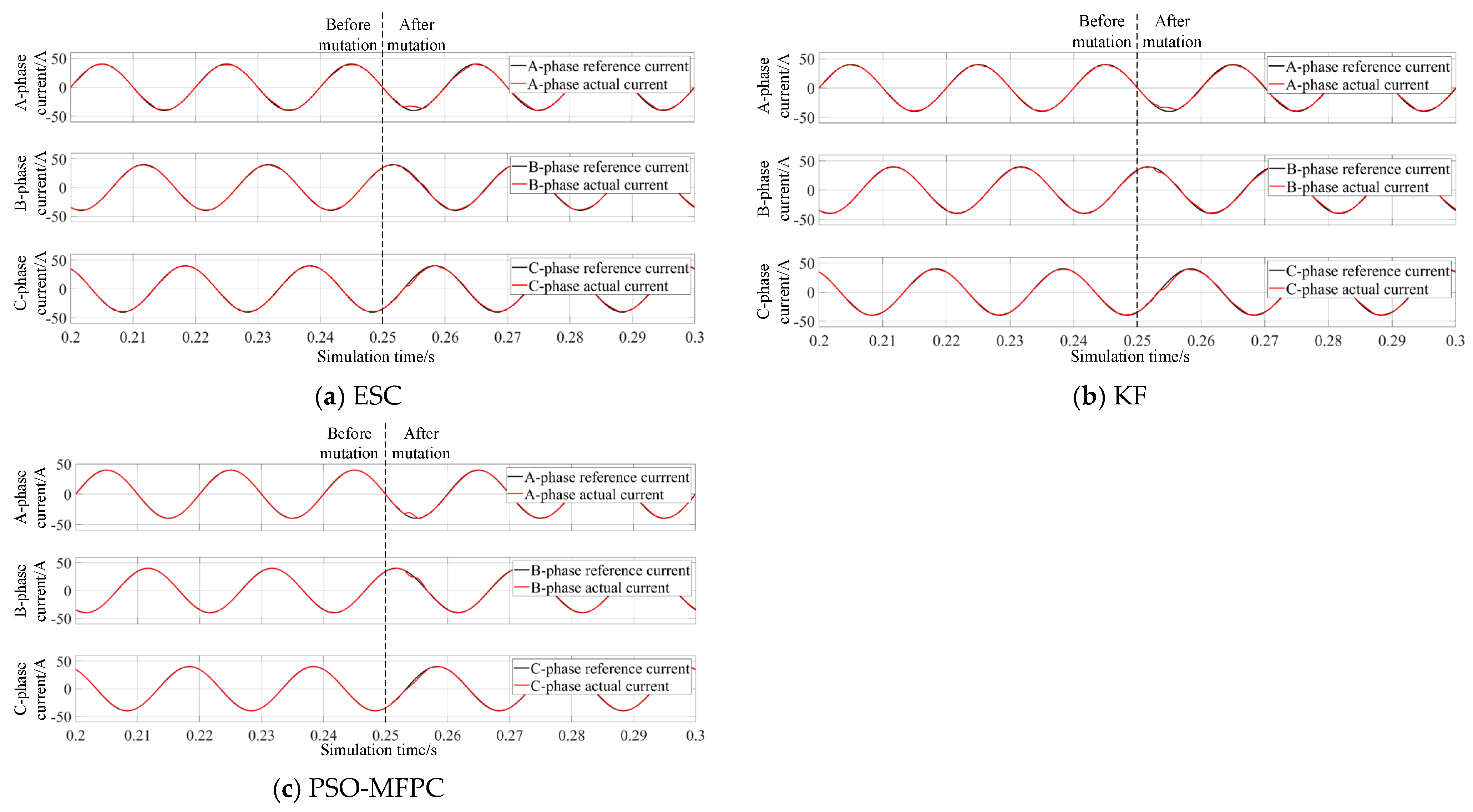
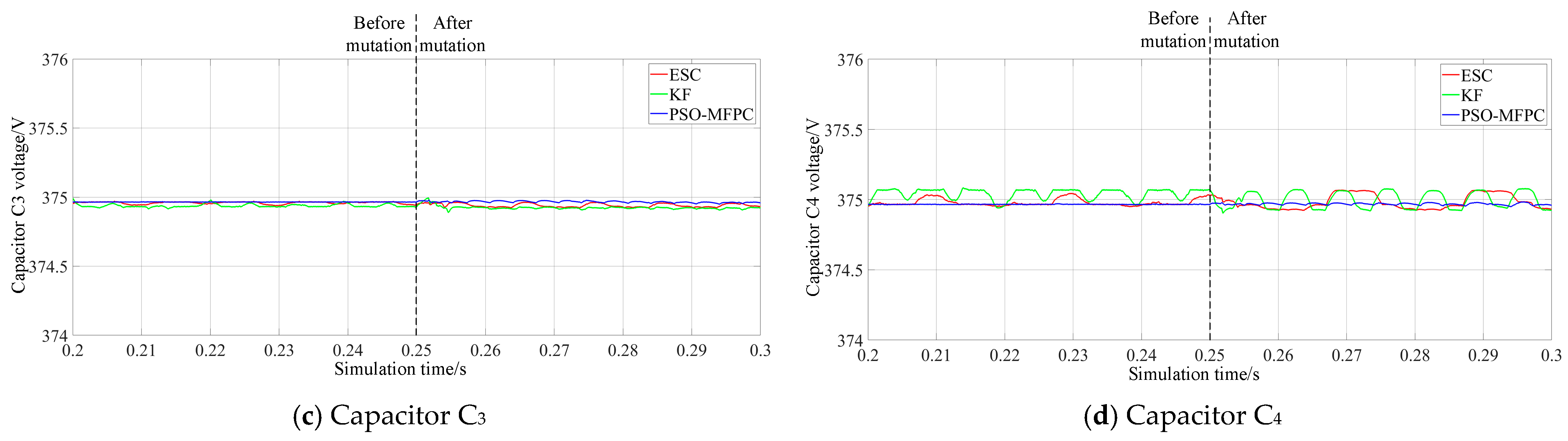
Subsequently, at 0.25 s, the resistive–inductive load is abruptly changed to 10 Ω and 30 mH while keeping the reference current amplitude unchanged. The corresponding current waveform, spectrum, and capacitor voltage waveform are shown in Figure 14, Figure 15, and Figure 16, respectively.
Figure 14.
Output current waveforms under conditions of a sudden change in load.
Figure 15.
THD spectra of the output currents under conditions of a sudden change in load.
Figure 16.
DC-side capacitor voltage waveforms under conditions of a sudden change in load.
From the above simulation results, it can be observed that under conditions of sudden load changes, the PSO-MFPC algorithm proposed in this study, after a brief current fluctuation, achieves superior current re-tracking performance with respect to the reference current compared with the other two algorithms. Moreover, while realizing the balancing of the DC-side capacitor voltages, it also ensures better current quality. These results indicate that the PSO-tuned control gain provides adequate robustness against parameter variations and external disturbances.
5.3. Tracking Control Performance for Three-Phase Currents at Different Sampling Frequencies
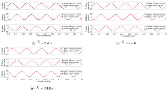
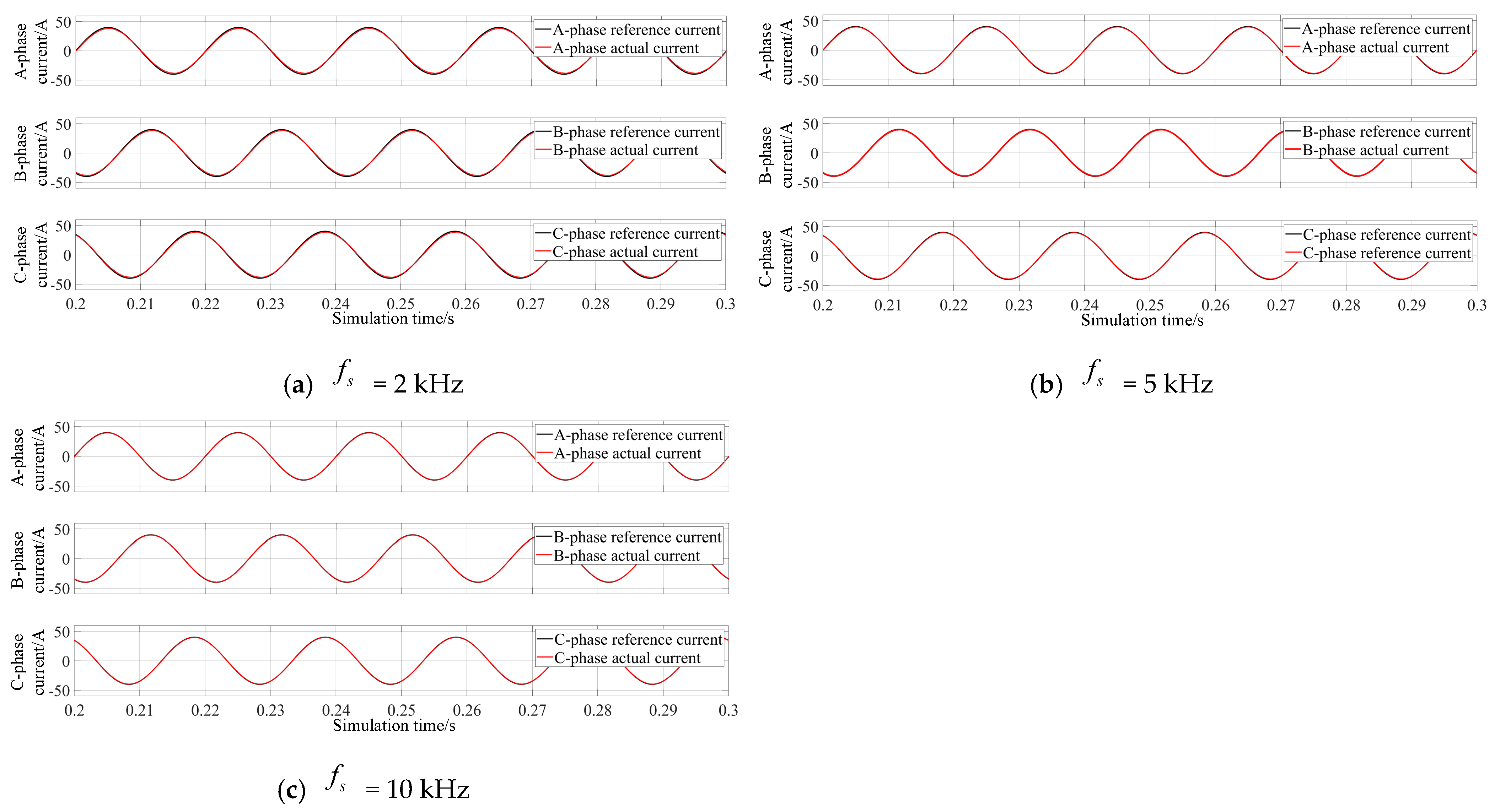
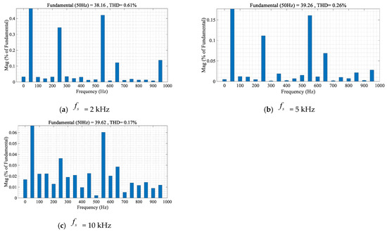
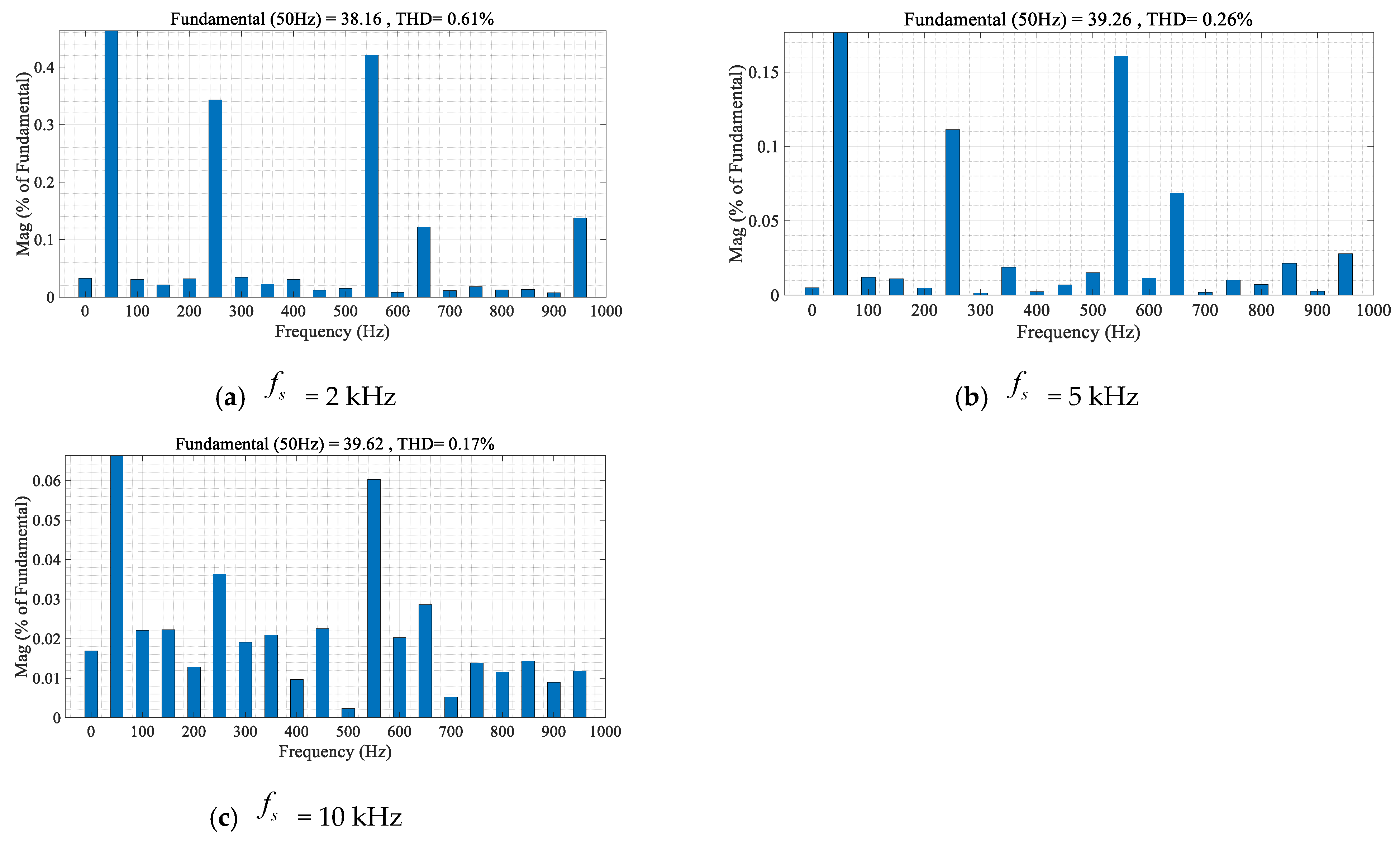
To further verify the effect of different sampling frequencies on three-phase current tracking control, the sampling frequencies were set to 2 kHz, 5 kHz, and 10 kHz. The reference current amplitude was maintained at 40 A with a frequency of 50 Hz. The corresponding three-phase current tracking output waveforms are shown in Figure 17, and the spectrum diagrams are presented in Figure 18. A comparison of Figure 17 and Figure 18 indicates that the higher sampling frequency , the better three-phase current tracking performance.
Figure 17.
Output current waveforms under different sampling frequencies.
Figure 18.
THD spectra of the output currents under different sampling frequencies.
5.4. Motor Load Control Performance
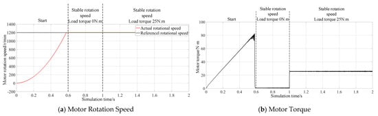
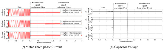
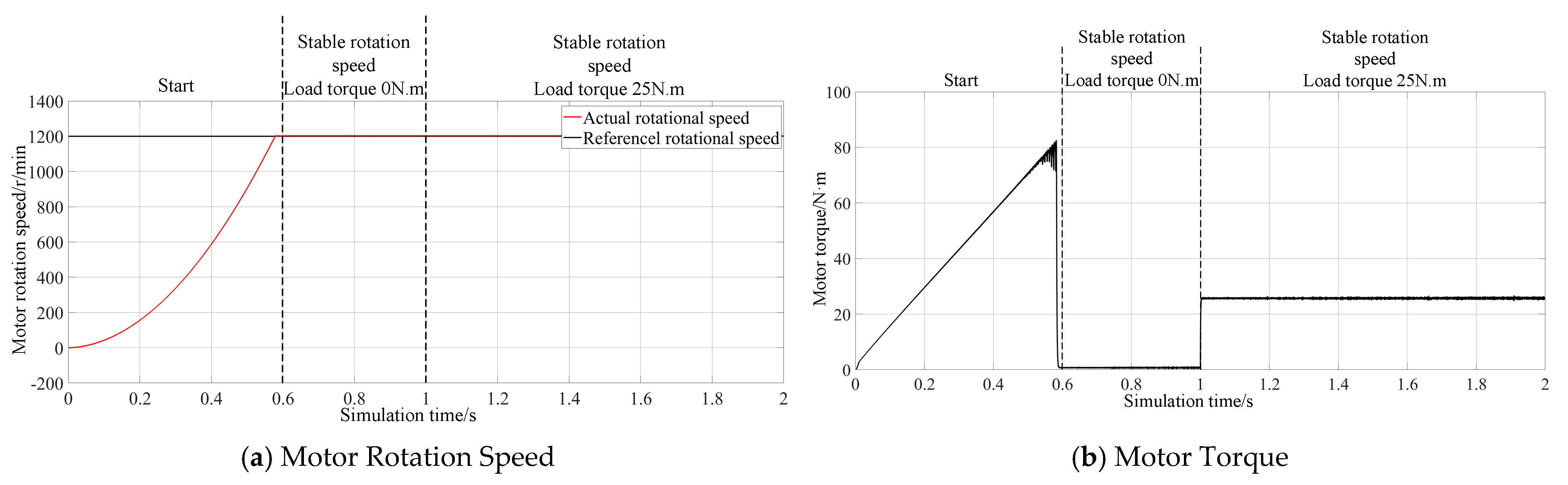
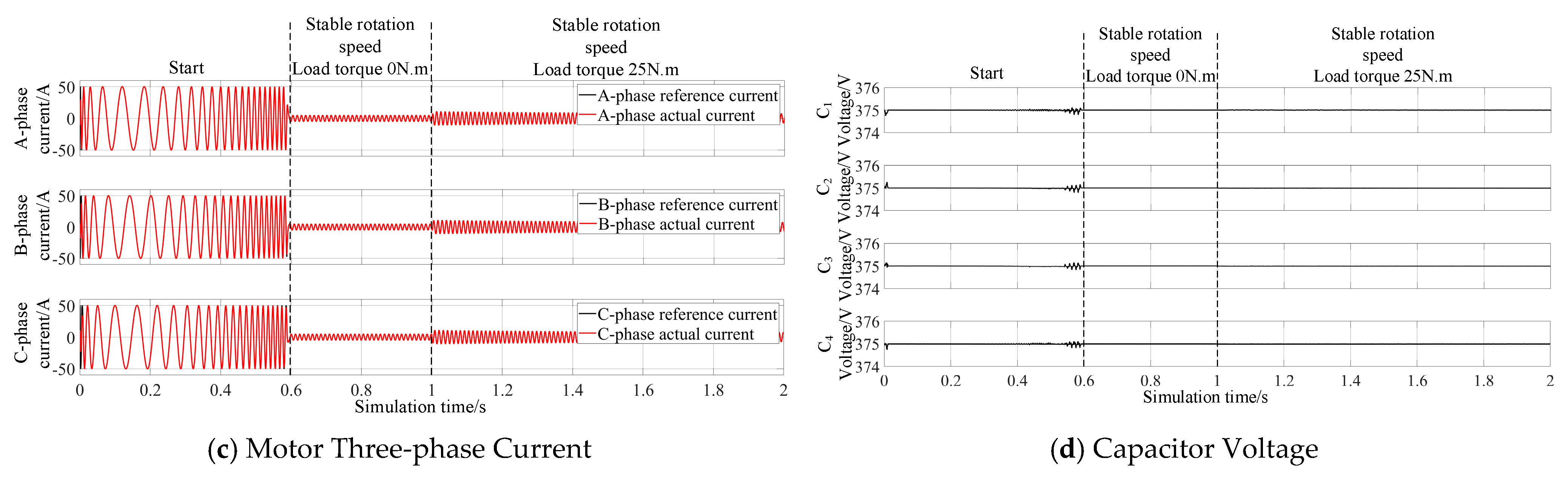
Subsequently, to verify the effectiveness of the proposed algorithm under motor load conditions, simulation verification was also conducted in the MATLAB/Simulink environment. In the simulation model, the load was replaced with a motor load, while the remaining parts of the model remained unchanged. The motor used in the model is an induction motor, and its parameters are based on those of the motors used on Shanghai Metro Line 2. The rated voltage is , the rated current is , the rated speed is , the rated power is , the power factor is 0.85, and the number of pole pairs is 4. The stator leakage inductance and rotor leakage inductance are both 1.511 mH, the stator–rotor mutual inductance is , the stator resistance is , and the rotor resistance is . The reference speed of the motor is set to 1200 r/min, and the load torque experiences a step change from 0 to 25 N·m at 1 s. Using the PSO algorithm, the optimal control gain of the ultra-local model is found to be 4.56. The simulation results are shown in Figure 19.
Figure 19.
Motor load simulation waveforms.
From the above simulation analysis, it can be concluded that when a motor load is adopted, the proposed PSO-based model-free predictive control algorithm can still ensure that the three-phase load currents effectively track the reference currents while maintaining the balance of the DC-side capacitor voltages. Meanwhile, the operating performance of the induction motor can also be guaranteed.
6. Conclusions
To address the issue in capacitor voltage-balancing control of the NPC five-level inverter where conventional MPC suffers from model–plant mismatch due to variations in system parameters, this paper proposes a simplified-vector-set improved MFPC algorithm based on PSO. The proposed method improves the performance and control accuracy of the control strategy by tuning the control gains using the adaptative inertia coefficient PSO algorithm and constructing a simplified vector set based on the deadbeat principle. A corresponding simulation model is then established in Simulink to verify both the proposed algorithm and the PSO-optimized control gains. The simulation results demonstrate that the proposed algorithm effectively addresses the nonlinear characteristics and dynamic complexities inherent in the NPC five-level inverter, including switching-induced disturbances, capacitor voltage coupling, and load/current transients. In addition, compared with MFPC methods based on extremum-seeking control and Kalman filtering, the proposed PSO-MFPC strategy achieves lower current THD (0.28%) and smaller capacitor voltage fluctuation (0.0001%) under steady-state conditions, while exhibiting superior robustness and tracking performance under dynamic conditions such as sudden reference current and load changes.
This study only verifies the proposed control strategy through simulation; further validation on a practical engineering platform is required in future work. In addition, in practical systems, the optimal control gain α may need to be retuned or adjusted through online adaptive mechanisms as operating conditions such as current frequency change, which also represents a direction for future research.
Author Contributions
Conceptualization, Z.X., Y.S. and Y.W.; Methodology, Z.X., Y.S. and Y.W.; Software, Z.X., Y.S. and Y.W.; Validation, Z.X., Y.S. and Y.W.; Formal analysis, Z.X., Y.S. and Y.W.; Investigation, Z.X., Y.S. and Y.W.; Resources, Z.X., Y.S. and Y.W.; Data curation, Z.X., Y.S. and Y.W.; Writing–original draft, Z.X.; Writing–review & editing, Q.Z.; Visualization, Q.Z.; Supervision, Q.Z.; Project administration, Q.Z.; Funding acquisition, Q.Z. All authors have read and agreed to the published version of the manuscript.
Funding
This research received no external funding.
Data Availability Statement
The original contributions presented in this study are included in the article. Further inquiries can be directed to the corresponding author.
Conflicts of Interest
The authors declare no conflict of interest.
References
- Chen, D.; Liu, Y.; Zhang, S. Switch Control Strategies of Three-level T-type Inverter. Control Eng. China 2022, 29, 927–934. [Google Scholar] [CrossRef]
- Duong, T.-D.; Nguyen, M.-K.; Nguyen, T.-T.; Cha, H.; Lim, Y.-C.; Choi, J.-H. Switching-Cell Structure-Based Generic Five-Level Current-Source Inverter. IEEE Trans. Ind. Electron. 2023, 70, 5696–5706. [Google Scholar] [CrossRef] [Scilit]
- Aghaei, H.; Babaei, E.; Sharifian, M.B.B. Two Compact Three-Phase Multilevel Inverters for Low-Voltage Applications. IEEE Trans. Power Electron. 2023, 38, 647–656. [Google Scholar] [CrossRef] [Scilit]
- Mehta, S.; Puri, V. A review of different multi-level inverter topologies for grid integration of solar photovoltaic system. Renew. Energy Focus 2022, 43, 263–276. [Google Scholar] [CrossRef] [Scilit]
- Lalili, D.; Berkouk, E.M.; Boudjema, F.; Lourci, N. Self balancing of DC link capacitor voltages using redundant vectors for SVPWM controlled five-level inverter. In Proceedings of the 5th International Multi-Conference on Systems, Signals and Devices, Amman, Jordan, 20–22 July 2008. [Google Scholar]
- Palanisamy, R. Mitigation of capacitor voltage unbalance and common mode voltage for 3-phase 5-Level NPC inverter using hexagonal SVPWM. e-Prime Adv. Electr. Eng. Electron. Energy 2024, 9, 100639. [Google Scholar] [CrossRef] [Scilit]
- Wu, Y.; Jia, H.; Deng, Y. Fast space vector pulse width modulation algorithm for neutralpoint clamped H-bridge five-level inverter. Electr. Mach. Control 2022, 26, 31–38. [Google Scholar] [CrossRef]
- Xiang, C.-Q.; Shu, C.; Han, D.; Mao, B.-K.; Wu, X.; Yu, T.-J. Improved Virtual Space Vector Modulation for Three-Level Neutral-Point-Clamped Converter with Feedback of Neutral-Point Voltage. IEEE Trans. Power Electron. 2018, 33, 5452–5464. [Google Scholar] [CrossRef] [Scilit]
- Shishkov, A.N.; Dudkin, M.M.; Maklakov, A.S.; Le, V.K.; Radionov, A.A.; Balabanova, V.S. An Improved Space Vector PWM Algorithm with a Seven-Stage Switching Sequence for Three-Level Neutral Point Clamped Voltage Source Inverters. Energies 2025, 18, 2452. [Google Scholar] [CrossRef] [Scilit]
- Li, L.; Yang, T.; Yuan, Y.; Cai, Z. Maximum power point tracking algorithm of a photovoltaic power generation system based on an improved finite set model predictive control strategy. Power Syst. Prot. Control 2021, 49, 28–37. [Google Scholar] [CrossRef]
- Annoukoubi, M.A.; Essadki, A.; Akarne, Y. Model predictive control of multilevel inverter used in a wind energy conversion system application. e-Prime Adv. Electr. Eng. Electron. Energy 2024, 9, 100717. [Google Scholar] [CrossRef] [Scilit]
- Guo, Z.; Quan, H.; Peng, Z.; Dai, Y. A High-Performance Model Predictive Control Strategy Based on Si/SiC Cascaded H-Bridge Inverter. Acta Electron. Sin. 2024, 52, 3000–3009. [Google Scholar] [CrossRef]
- Hu, C.; Sun, X.; Zhang, Y.; Rui, T.; Yin, Z.; Feng, Z.; Wang, Y. Optimal switching sequence model predictive current controlfor grid connected inverter. Electr. Mach. Control 2024, 28, 135–142. [Google Scholar] [CrossRef]
- Bebboukha, A.; Meneceur, R.; Chouaib, L.; Anees, M.A.; Elsanabary, A.; Mekhilef, S.; Bakeer, A.; Harbi, I.; Zaitsev, I.; Bajaj, M. Finite control set model predictive current control for three phase grid connected inverter with common mode voltage suppression. Sci. Rep. 2024, 14, 19832. [Google Scholar] [CrossRef] [Scilit]
- Zhang, X.; Zhang, L.; Zhang, Y. Model Predictive Current Control for PMSM Drives with Parameter Robustness Improvement. IEEE Trans. Power Electron. 2019, 34, 1645–1657. [Google Scholar] [CrossRef] [Scilit]
- Guazzelli, P.R.U.; Pereira, W.C.d.A.; de Oliveira, C.M.R.; de Castro, A.G.; de Aguiar, M.L. Weighting Factors Optimization of Predictive Torque Control of Induction Motor by Multiobjective Genetic Algorithm. IEEE Trans. Power Electron. 2019, 34, 6628–6638. [Google Scholar] [CrossRef] [Scilit]
- Zhou, Y.; Li, H.; Liu, R.; Mao, J. Continuous voltage vector model-free predictive current control of surface mounted permanent magnet synchronous motor. IEEE Trans. Energy Convers. 2019, 34, 899–908. [Google Scholar] [CrossRef] [Scilit]
- Wang, Y.; Li, H.; Liu, R.; Yang, L.; Wang, X. Modulated Model-Free Predictive Control with Minimum Switching Losses for PMSM Drive System. IEEE Access 2020, 8, 20942–20953. [Google Scholar] [CrossRef] [Scilit]
- Yu, S.; Liu, S.; Huang, S.; Tang, B.; Wang, Z. Model-Free Predictive Current Control of Doubly-Fed Induction Generators Based on ESO and Sliding Mode Compensator. Arab. J. Sci. Eng. 2025, 1–16. [Google Scholar] [CrossRef] [Scilit]
- Mai-Van, C.; Duong-Minh, S.; Tran-Huu, D.; Binh-Pho, B.; Vu, P. An improved method of model predictive current control for multilevel cascaded H-bridge inverters. J. Electr. Eng. 2021, 72, 1–11. [Google Scholar] [CrossRef] [Scilit]
- Yuan, Q.; Yan, L.; Yang, N. A Simplified Model Predictive Voltage Control for the NPC H-bridge Cascaded Five-level Inverters Based on the Rectangular Region Classification. Proc. CSEE 2023, 43, 4758–4769. [Google Scholar] [CrossRef]
- Andino, J.; Arcos-Aviles, D.; Guinjoan, F. Fast-execution neural-network-based modulated model predictive control for a three-phase three-level inverter. Control Eng. Pract. 2025, 165, 106595. [Google Scholar] [CrossRef] [Scilit]
- Wei, Y.; Young, H.; Ke, D.; Wang, F.; Rodríguez, J. Model-Free Predictive Current Control Using Extended Affine Ultralocal for PMSM Drives. IEEE Trans. Ind. Electron. 2024, 71, 6719–6729. [Google Scholar] [CrossRef] [Scilit]
- Huo, X.; Li, P. Parameter-free ultralocal model-based predictive current control method for grid-tied inverters using extremum seeking control. Control Eng. Pract. 2025, 157, 106253. [Google Scholar] [CrossRef] [Scilit]
- Wu, Q.; Zhang, H.; Xiang, X.; Li, H. Enhanced Model-Free Predictive Current Control for PMSM Based on Ultra-Local Models: An Efficient Approach for Parameter Mismatch Handling. Energies 2025, 18, 3049. [Google Scholar] [CrossRef] [Scilit]
- Kumar, R.; Gupta, R.A.; Pratap, K.S. Implementation and Analysis of Five-Level inverter with Space Vector PWM Algorithm. In Proceedings of the 2006 IEEE International Conference on, Mumbai, India, 15–17 December 2006. [Google Scholar]
- Yaramasu, V.; Wu, B.; Rivera, M.; Narimani, M.; Kouro, S.; Rodriguez, J. Generalised approach for predictive control with common-mode voltage mitigation in multilevel diode-clamped converters. IET Power Electron. 2015, 8, 1440–1450. [Google Scholar] [CrossRef] [Scilit]
- Fliess, M.; Join, C. Model-free control. Int. J. Control 2013, 86, 2228–2252. [Google Scholar] [CrossRef] [Scilit]
- Abid, A.; Bakeer, A.; Albalawi, H.; Bouzidi, M.; Lashab, A.; Chub, A.; Zaid, S.A. Model-Free Predictive Control for Improved Performance and Robustness of Three-Phase Quasi Z-Source Inverters. IEEE Access 2024, 12, 87850–87863. [Google Scholar] [CrossRef] [Scilit]
- Zhang, Y.; Jin, J.; Huang, L. Model-Free Predictive Current Control of PMSM Drives Based on Extended State Observer Using Ultra-local Model. IEEE Trans. Ind. Electron. 2021, 68, 993–1003. [Google Scholar] [CrossRef] [Scilit]
- Cai, S.; Zhang, Z. Research on Model-Free Control of PMSM with Low Parameter Sensitivity Based on Nonlinear Extended State Observer. Electr. Mach. Control Appl. 2025, 52, 192–200. [Google Scholar] [CrossRef]
- Wen, Z. Proficient in MATLAB Intelligent Algorithm, 1st ed.; Tsinghua University Press: Beijing, China, 2015; pp. 121–125. [Google Scholar]
- Cortes, P.; Kouro, S.; La Rocca, B.; Vargas, R.; Rodriguez, J.; Leon, J.I.; Vazquez, S.; Franquelo, L.G. Guidelines for weighting factors design in Model Predictive Control of power converters and drives. In Proceedings of the 2009 IEEE International Conference on Industrial Technology, Churchill, Australia, 10–13 February 2009. [Google Scholar]
- Zhang, Y.; Shi, L.; Cheng, F.; Han, L. APF Model Predictive Control Based on Improved Virtual Multi-vector. Power Electron. 2022, 56, 133–136. [Google Scholar]
- Tang, X.; Zhang, Z.; Liu, X.; Liu, C.; Jiang, M.; Song, Y. A Novel Field-Oriented Control Algorithm for Permanent Magnet Synchronous Motors in 60° Coordinate Systems. Actuators 2023, 12, 92. [Google Scholar] [CrossRef] [Scilit]

Disclaimer/Publisher’s Note: The statements, opinions and data contained in all publications are solely those of the individual author(s) and contributor(s) and not of MDPI and/or the editor(s). MDPI and/or the editor(s) disclaim responsibility for any injury to people or property resulting from any ideas, methods, instructions or products referred to in the content. |
© 2026 by the authors. Licensee MDPI, Basel, Switzerland. This article is an open access article distributed under the terms and conditions of the Creative Commons Attribution (CC BY) license.