


Abstract
Efficient condensation is fundamental for high-performance passive two-phase heat transfer devices, such as grooved heat pipes, which are widely used in thermal management for electronic, automotive, aerospace and energy systems. Enhancing condensation heat transfer requires precise control of the condensate distribution and liquid drainage, which can be achieved through the optimization of fin geometry. This study investigates the condensation heat transfer over rectangular, trapezoidal and inverted trapezoidal fins under horizontal and vertical downflow conditions for four refrigerants (R134a, R245fa, R290 and R717) by means of three-dimensional steady-state CFD simulations using the volume-of-fluid (VOF) method. The fin surfaces, inspired by grooved wick heat pipes, are aimed at improving condensate removal and overall condensation heat transfer. The numerical model is validated through comparison with experimental data taken from the literature. Numerical results show that ammonia achieves the highest condensation heat transfer, due to its favorable thermophysical properties. In horizontal flow, inverted trapezoidal and rectangular fins yield up to 10% higher heat transfer than trapezoidal fins, with the inverted trapezoid promoting a more uniform condensate film. Vertical downflow enhances gravity-driven drainage, producing thinner, more stable films and up to 88% higher local heat flow rates in the grooves. These results provide insights into the coupled influence of geometry, working fluid, and flow conditions on condensation mechanisms, offering useful guidelines for the design and optimization of condensers in passive heat transfer devices.
1. Introduction
The growing demand for energy efficiency, sustainability and reliable thermal management has intensified the need for high-performance heat transfer systems [1,2]. From power generation and industrial processes to electronics and electric mobility, effective heat management is essential to ensure stable operation and prevent thermal failure. Conventional active cooling systems, such as vapor-compression or liquid-loop setups, often face limitations related to complexity, energy consumption and maintenance requirements.
In this context, passive two-phase heat transfer devices, such as heat pipes and loop heat pipes, have attracted increasing attention due to their ability to transport large heat loads with minimal temperature gradients and without any external power input [3,4,5]. Among them, grooved heat pipes play an important role, using capillary grooves along the inner wall to return the condensate to the evaporator instead of a porous wick structure, providing a simpler and often more manufacturable solution for high-heat-flux applications. Due to these advantages, grooved heat pipes are being increasingly adopted in various fields, including thermal management of power electronics and electric vehicles, aerospace systems, waste heat recovery, and nuclear and renewable energy systems. Their compactness, reliability and passive operation make them suitable for next-generation sustainable thermal systems.
The overall performance of a grooved heat pipe is strongly influenced by the phase-change phenomena occurring within it, particularly the condensation process in the condenser section, which governs both the liquid return via the grooves and the overall heat removal capability. A detailed understanding of condensation mechanisms and their enhancement strategies is therefore crucial for improving the efficiency of these systems [6].
Two main strategies are widely explored to promote condensation: increasing the effective heat transfer surface area and reducing the thickness of the liquid film. A thinner condensate layer minimizes the thermal resistance concentrated within the film itself, thereby improving the overall heat transfer [7]. Several methods for reducing the film thickness have been proposed in the literature, including gravitational drainage, vapor shear, centrifugal forces, electromagnetic fields [8] and wall suction through porous media [9,10].
Among these, surface finning stands out as one of the most efficient passive techniques [11]. It enhances heat transfer without relying on external forces or consuming additional energy. By introducing microscale or mesoscale structures, such as pin fins, dimples, protrusions, metal foams, or twisted tape inserts, finned surfaces increase the effective area for condensation and promote more efficient condensate drainage through the combined action of gravity, surface tension, and capillary forces [12].
However, fabricating such complex geometries at a small scale poses significant challenges to traditional machining methods (e.g., milling, shearing, drilling, casting). Nevertheless, recent advances in additive manufacturing have opened the pathway for the design and fabrication of customized geometries that are tailored to specific requirements. A growing field of research has demonstrated the potential of this technology in developing high-performance thermal systems [13,14,15,16].
Despite the extensive research on the geometry optimization of finned surfaces for improved heat transfer [17,18,19], the influence of surface geometry on the condensation process, especially in the typical flow conditions expected inside heat pipes, remains only marginally addressed in the literature. The mechanisms governing condensate film distribution and drainage within grooved channels are still not fully understood, even though they play a decisive role in the overall thermal performance. Understanding these mechanisms is therefore essential to guide the geometry optimization of high-performance heat pipe condensers.
Only a limited number of studies have investigated the optimization of fin geometry for condensation heat transfer. Among them, Barakhovskaia and Marchuk [20] identified the most appropriate fin shape for condensation experiments under microgravity, which is able to guarantee a stable flow of the condensate film under the effect of a constant capillary pressure gradient. Glushchuck et al. [21,22] experimentally tested a 10 mm tall, curved brass fin, cooled from the base and designed to maximize the condensate flux under various gravity conditions during a parabolic flight campaign. In [21], they studied a cylindrical fin that was 24 mm in height and 3 mm in width and concluded that areas with high surface tension, such as those near the corner and the sides of the fins, provide 10–15% of the total heat load and, therefore, their effect on the heat transfer is non-negligible. Kedzierski and Webb [23] experimentally demonstrated that large surface curvatures and curvature gradients enhance condensate drainage driven by surface tension. Their results indicated that fins with pronounced curvature, such as tall and slender geometries, promote more effective condensate removal and, consequently, higher heat transfer coefficients. Ho et al. [24,25] and Ho and Leong [26] investigated vapor condensation on vertical aluminum-alloy plates fabricated by selective laser melting (SLM) with integrated pin-fin arrays (conical, sinusoidal, cylindrical), studying fin shape and height, and performing visual observations of fluid retention height and its impact on heat transfer enhancement. Their results demonstrated that optimized pin-fin geometries can reduce the liquid retention height and yield to heat transfer coefficients up to 50% higher than those of the equivalent longitudinal fins. In particular, compared to cylindrical and longitudinal pin fins, conical and sinusoidal designs enhanced heat transfer by promoting condensate drainage via surface-tension effects, with conical fins reducing retention through their 3D curvature and sinusoidal fins guiding condensate from tip to base, both resulting in higher heat transfer coefficients.
Building upon the insights gained from experimental studies, several modeling approaches have been developed. Adamek and Webb [27] developed an analytical model to predict the condensation rate in the drainage channel of a vertical finned plate. While developed for rectangular geometry, the model can be adapted to other shapes, and it showed excellent agreement with the experimental data by Kedzierski and Webb [23]. Marchuk and co-authors developed theoretical models to optimize fin shapes for maximizing condensate outflow. In refs. [28,29], they applied the calculus of variations and lubrication theory to identify optimal curved surfaces. In later works [30,31], they extended this analysis to three-dimensional models for film condensation on curved surfaces. Wang et al. [32] performed a numerical study of film-wise condensation on fluted fins in a vertical tube. They conducted a systematic analysis on fins’ number and geometry and derived a condensate thickness equation by simplifying the Navier–Stokes equations. Ho et al. [33] developed a theoretical model for film-wise condensation of steam on 3D pin fins fabricated via SLM, accurately predicting the experimental average heat transfer coefficient with a maximum deviation of 8.3%.
Currently, the design of two-phase flow systems relies on semi-empirical correlations [34,35] which only provide accurate predictions for working fluids and fin geometries that are included in the database used for the correlation development. As a result, the development of accurate and widely applicable models often requires extensive experimental efforts, both to generate new data and to validate predictive tools [36]. An alternative approach lies in the use of numerical models based on the Navier–Stokes equations, coupled with energy conservation principles. These models not only enable the prediction of finned surface heat transfer but also provide insight into the complex dynamics of condensate films. In this context, computational fluid dynamics (CFD) simulations are expected to play a growing role, offering the potential for accelerated design procedures and a deeper understanding of the underlying physical mechanisms governing two-phase heat transfer. While topology optimization techniques have shown great success in single-phase applications [37,38], their extension to two-phase flows remains limited. The challenges arise from the complexity of multiphase interactions, the necessity of advanced interface capturing models, and the complex coupling between momentum, heat and mass transfer processes. Moreover, relatively few studies in the literature have tackled the detailed modeling of condensation over finned surfaces. The flow regimes at low mass flux, characterized by the dominance of surface tension forces and the presence of interfacial instabilities, present significant numerical challenges. Despite their complexity, low mass fluxes are of considerable practical relevance. They are frequently encountered in passive thermal management devices such as heat pipes [3], but are also in vapor compression systems operating under partial load conditions. Addressing the modeling challenges in these low flow rates regimes is therefore critical to the advancement of the design and performance of two-phase heat transfer systems.
Over the past decades, the volume-of-fluid (VOF) method [39] has emerged as a reliable computational technique for simulating two-phase flows, which are particularly effective in tracking liquid–vapor interfaces [40]. At the same time, the Lee model [41] has gained wide adoption in the literature [42,43], due to its simplicity, capability to simulate phase change without a predefined interface, and applicability under a wide range of operating conditions.
Building upon the capabilities of these numerical methods, the present study aims to expand the limited knowledge on condensation heat transfer in grooved heat pipes by performing steady-state numerical simulations with various fin geometries. Specifically, three-dimensional CFD simulations are carried out in Ansys Fluent, using the volume-of-fluid (VOF) method to evaluate the effects of fin shape on condensate film distribution and local heat flux profiles. The simulations are performed under conditions that are representative of condensation in grooved heat pipes, with a saturation temperature of 40 °C and low mass fluxes (5–30 kg m−2 s−1). Although condensate return in grooved heat pipes is capillary-driven, a fixed mass flux is imposed here to reproduce representative local condensation conditions and to enable controlled evaluation of fin-induced drainage and heat transfer enhancement, as may also occur under low-flow or forced-flow regimes in other two-phase systems (e.g., loop or mechanically pumped heat pipes).
The numerical model is validated against the experimental data reported in the literature to ensure accuracy and reliability. Upon validation, three fin geometries (rectangular, trapezoidal, and inverted trapezoidal) are simulated to investigate the influence of geometry configuration on heat transfer and condensate flow characteristics. Moreover, in the context of the global phase-down of hydrofluorocarbons (HFCs) associated with their high global warming potential (GWP) [29], the study includes a comparative performance analysis of conventional refrigerants (R134a, R245fa) and low-GWP natural alternatives, such as propane and ammonia.
2. Numerical Model
The next sections outline the adopted numerical approach, starting with the description of the VOF method and followed by the Lee model [41] to account for phase change.
2.1. VOF Method
The volume-of-fluid method is one of the most widely used approaches in computational fluid dynamics (CFD) to track the vapor–liquid interface without using any empirical closure law to model the interaction between the phases. A scalar field called “volume fraction” (i.e., ) is used, which represents the portion of the volume in the computational cell filled with one phase.
In the VOF method, the two-phase mixture is considered as a single fluid whose properties vary according to the volume fraction . The properties of the two-phase mixture (viscosity , density , thermal conductivity ) are calculated in each computational cell, using an arithmetic mean:
For the simulations, four different working fluids have been considered: R134a, R245fa, R290 (propane) and R717 (ammonia). All thermodynamic and transport properties have been considered to be temperature dependent and are computed using REFPROP 10.0 [44] (Table 1).
Table 1.
Thermodynamic and transport properties of R134a, R245fa, R290 and R717 at 40 °C saturation temperature, obtained from REFPROP 10.0 (Lemmon et al. [44]).
The following continuity, volume fraction and energy equations, which include the mass source term due to phase change, are solved:
where T is the cell temperature, is the effective thermal conductivity, is the enthalpy of vaporization, and is the specific heat at constant pressure.
In the momentum equation, the surface tension force is also taken into account:
The momentum equation accounts for the convective momentum term , pressure gradient (), viscous and turbulent diffusion , gravitational acceleration () and surface tension force () acting at the vapor–liquid interface.
In Ansys Fluent, two surface tension models are available: continuous surface force (CSF) and continuous surface stress (CSS). The first approach evaluates surface tension as a pressure jump across the interface, computed using the continuum surface force (CSF) model proposed by Brackbill et al. [45]. In the CSF method, the surface tension force is computed as follows:
where is the surface tension and is the surface curvature, evaluated as follows:
The CSS method does not require explicit curvature calculations, making it more physically accurate in areas that are adjacent to an undercut. Furthermore, its conservative formulation inherently accounts for surface tension effects without the need for additional correction terms to handle variable surface tension.
The least squares cell-based method is used for the evaluation of gradients. For VOF calculations, the modified High-Resolution Interface Capturing (HRIC) scheme [46] is employed. Pressure interpolation is handled with the Pressure Staggering Option (PRESTO!) scheme [47], while the SIMPLE algorithm [48] is used for pressure–velocity coupling. Convective terms in the momentum, turbulence, and energy equations are discretized using a First-Order Upwind scheme [49]. As reported by Da Riva et al. [50], the effect of mass flux on condensation heat transfer can be predicted only when the turbulence in the liquid film is considered. Depending on the mass flux and the position along the fin surface, both laminar and turbulent regimes may occur, since the local film thickness and velocity vary both axially and along the curvilinear coordinate. For this reason, turbulence is modeled using the SST k-ω approach (for a more detailed discussion, refer to Appendix A). In this method, the Menter’s low-Reynolds-number shear stress transport (SST) model [51] is used throughout the computational domain.
2.2. Phase-Change Modeling
In order to achieve higher modeling accuracy, it is recognized that a small temperature drop occurs at the liquid–vapor interface, due to molecular kinetics during condensation. This drop is confined to a very thin region on the vapor side, typically spanning only a few molecular mean free paths, and ensures a finite condensation rate. Various correlations exist in the literature to estimate the interfacial heat transfer coefficient (e.g., Berman [52]; McNaught and Butterworth [53]; Wang and Rose [54]). For the operating conditions considered in this study (Tsat = 40 °C), these correlations predict interfacial heat transfer coefficients in the order of 106–107 W m−2 K−1. Typical condensation heat transfer coefficients under the present operating conditions are instead in the order of 103–104 W m−2 K−1. Therefore, the interfacial thermal resistance is negligible, and the interfacial temperature is assumed to be equal to the saturation temperature. This assumption is commonly adopted in the literature (e.g., Da Riva et al. [40,50]). Nebuloni and Thome [55] explicitly accounted for interfacial mass transfer resistance in film condensation within mini- and micro-channels of various cross-sectional geometries, and they concluded that its effect is negligible during condensation of R134a and ammonia under the investigated operating conditions.
The phase change is modeled using the numerical method proposed by Lee [41], which defines the source term S, which is expressed as follows:
where r is an empirical coefficient called the mass transfer intensity factor.
To avoid numerical convergence issues, the mass transferred between phases at each computational step should never exceed the total mass of the first phase that is initially present in the cell. Accordingly, the source term is proportional to the products or that represent the amount of vapor or liquid present in the cell, respectively. This ensures that cells in the vapor phase do not fall below the saturation temperature, and cells in the liquid phase do not exceed it. At convergence, the interface reaches the saturation temperature, while the liquid and vapor cells stabilize at slightly lower and higher temperatures, respectively. As previously discussed in [42,43], the optimal value of the coefficient r strongly depends on the specific problem, and suitable values must be determined for each case. It varies with the fluid, geometry and mesh resolution. With a coarse mesh, the VOF method is unable to accurately capture the liquid–vapor interface, leading to unphysical condensation patterns. Progressive mesh refinement, ensuring an adequate number of cells across the developing liquid film, results in numerical predictions that asymptotically approach a grid-independent solution. In parallel, it was observed that finer meshes required proportionally higher values of the factor r to maintain thermodynamic equilibrium at the interface (i.e., an interfacial temperature equal to the saturation temperature). However, excessively high values of r introduced numerical instabilities due to the stiffness of the associated source term. In the present work, with a mesh consisting of approximately 5 million elements, a value of r ≈ 106 s−1 was selected, ensuring that the deviation between the area-averaged interfacial temperature and the saturation temperature remained within 0.5 K. Further increases in the phase-change coefficient beyond this order of magnitude result in negligible variations in the liquid film thickness (with a mean absolute percentage error of about 3%) and in the overall heat transfer rate (below 2%), indicating convergence with respect to both interfacial position and condensation heat transfer predictions.
2.3. Computational Domain, Meshing and Boundary Conditions
This study investigates the thermal performance during condensation of four refrigerants (R134a, R245fa, R290 and R717) on finned surfaces, each characterized by a different fin shape: rectangular, trapezoidal and inverted trapezoidal. Figure 1 schematically illustrates the numerical setup and boundary conditions for the rectangular fin; the same conditions are applied to the other two geometries. The model adopts a simplified 3D half-domain representation, assuming symmetry across both the central plane and the lateral wall to replicate a periodic array of fins that represent the grooved condensing structures used in wick heat pipes. Adiabatic boundary conditions are applied to the solid walls at both the inlet and outlet of the modeled geometry to prevent non-physical heat transfer at the axial edges. Saturated vapor at 40 °C enters the domain, and condensation is driven solely by heat removal through the finned surface, where a constant wall temperature of 30 °C is imposed at the bottom boundary.
Figure 1.
Computational domain and boundary conditions for the rectangular fin geometry. The cross-sectional view (left) shows the imposed symmetry planes and the constant wall temperature applied at the fin base. The isometric view (right) illustrates the three-dimensional half-domain representation, including the vapor inlet and outlet boundaries.
The inlet vapor mass flux is varied between 5 and 30 kg m−2 s−1. The application of a constant mass flux does not allow to reproduce the overall operation of a complete heat pipe, in which the condensate return is governed by capillary pressure generated within the grooved structure. Instead, the present approach is intended to represent controlled local condensation conditions within the condenser section, enabling a systematic investigation of the effect of fin geometry, working fluid, mass flux, and orientation on liquid film behavior and local heat transfer mechanisms.
All simulations are performed under steady-state conditions. Two fin orientations are considered for the simulations: horizontal and vertical. Accordingly, the gravitational acceleration vector is aligned along the y-axis for the horizontal configuration and along the z-axis for the vertical one. Figure 1 also shows the direction of the imposed flow. The fin height is 3 mm, the base width is 2.5 mm and the domain length is 30 mm.
To accurately capture the condensate film profile, evaluated at three axial positions (10 mm, 15 mm and 20 mm from the inlet, as shown in Figure 2), a static mesh with local refinement near the fin surface is employed. Each fin geometry is discretized with approximately 5 million mesh elements. A mesh independence study (Appendix B) demonstrated that, relative to the medium mesh (2.5 million elements), further refinement to 5 million elements resulted in variations of less than 2% in the local liquid film thickness and below 5% in the mean heat flux. Combined with the convergence observed with respect to the phase-change coefficient, these results confirm that the main heat transfer trends and enhancements discussed in this work are robust with respect to numerical sensitivity. Figure 2 also illustrates the mesh refinement near the corners and the base of the rectangular fin. Following the recommendation in [47], regions where surface tension effects dominate are discretized with quadrilateral cells to ensure better interface alignment and improved numerical stability.
Figure 2.
Computational mesh near the rectangular fin surface, highlighting local refinement at the fin corners (left) and base (right), where surface tension effects dominate. Axial planes along the fin z-coordinate indicate where the liquid film thickness and heat flux are evaluated.
3. Validation of the Numerical Method
To ensure the accuracy and reliability of the numerical model, a two-stage validation strategy has been implemented. The first step consists of an analytical validation, through which the results of two-dimensional simulations are compared with theoretical predictions derived from Nusselt’s film condensation theory [56]. This comparison, detailed in Appendix C, demonstrates excellent agreement between the numerical outcomes and the analytical solution.
To further assess the model’s predictive capability, the second stage of validation, presented in Section “Simulations Against Experimental Data”, is based on a comparison with the available experimental data from the literature. Although the experimental validation uses HFE-7100 (data taken from Glushchuk et al. [21], Brussels, Belgium), its main purpose is to assess the model’s capability to capture the dominant physical mechanisms governing film-wise condensation and liquid film distribution on finned surfaces. The extension to other refrigerants relies on the explicit inclusion of thermophysical properties in the governing equations, which directly account for differences in surface tension, latent heat, and liquid thermal conductivity. A comprehensive experimental validation for the refrigerants considered in this study is planned through dedicated experimental campaigns.
Simulations Against Experimental Data
To validate the numerical model, the experimental results reported by Glushchuk et al. [21] are considered here. In their investigation, they measured the liquid film thickness formed during condensation of HFE-7100 (properties available in [57]) on a single cylindrical fin under various gravitational conditions. Figure 3a shows the fin geometry used for validation under standard gravity . As shown in the figure, the fin surface is divided into five distinct regions, based on the predominant force governing the liquid flow: gravitational forces or surface-tension pressure gradients (STPG) [21]. In particular, surface-tension effects dominate near the fin tip and along the fin corners (Regions 1–3), where curvature variations generate strong pressure gradients that drive the condensate either toward the tip or the fin bottom. Conversely, gravity becomes the main driving force along the cylindrical part of the fin (Region 4), where the effect of STPG is negligible. Closer to the film–meniscus transition (Region 5), both gravity and surface-tension effects interact as the condensate film adapts to the curvature of the surface. The optical system used to measure the liquid film thickness, comprising an afocal setup and relying on image analysis from a high-speed camera, displayed a measurement precision of 6 μm.
Figure 3.
Validation of the numerical model using Glushchuck et al.’s [21] experimental data under normal gravity conditions. (a) Schematic of the fin geometry showing the boundary conditions and regions dominated by surface tension (Regions 1–3) or gravity (Regions 4–5). (b) Comparison of the liquid film thickness along the fin arc length s between experimental measurements (blue markers) and numerical predictions (dotted line).
The developed numerical model adopts a simplified two-dimensional axisymmetric representation of the fin cross-section. Boundary conditions are chosen to closely replicate the experimental setup, which operates according to the thermosiphon principle. Specifically, the pressure inlet is imposed at the top boundary, introducing saturated vapor at 47.5 °C. The right boundary is treated as adiabatic with a slip condition, while the pressure outlet is imposed at the bottom. On the left boundary, the axisymmetric condition is applied. No-slip conditions are imposed on the fin surfaces, and different constant temperatures are applied along specific regions of the fin’s arc length. These temperature values were taken from the reference study, where they were obtained through a finite element method (FEM) analysis of the fin. Using these values allows for the heat conduction within the brass material to be neglected in the present study, focusing instead on the thermal field at the liquid–vapor interface. A hybrid mesh is employed, with local refinement in the phase-change region to ensure an accurate resolution of the condensate distribution.
Figure 3b compares the numerically predicted liquid film thickness with experimental data along the fin surface. Overall, the numerical model reproduces the condensate distribution accurately. Regions 2 and 3, located around the fin corner where surface tension drives the liquid flow and curvature effects, are strong and exhibit an average deviation of approximately 6.1 μm, within the experimental uncertainty. Region 4, along the vertical fin wall where gravitational drainage gradually reduces the thickness of the liquid film, shows similarly low discrepancies. At the fin base (region 5), where the liquid accumulates and gravitational forces dominate, the mean difference increases to 8.7 μm. The largest mean deviation (20.5 μm) is observed in region 2 near the corner; however, considering that the local film thickness in this region ranges between 107 μm and 346 μm, the relative error remains reasonably small. These results demonstrate that the numerical model successfully captures both the magnitude and the distribution of the condensate film along the fin surface, confirming its capability to predict fin-induced drainage under the combined influence of surface tension and gravity.
4. Numerical Results: Horizontal Configuration
In this section, the numerical results for the horizontal configuration are presented. First, the liquid film thickness and heat transfer results for ammonia condensation over the trapezoidal fin geometry are analyzed. The observed trends for R717 are consistent with those obtained for R134a, R245fa and R290.
Figure 4a presents the condensate distribution at three different axial positions of the fin at mass fluxes of 5, 10 and 30 kg m−2 s−1. At these mass fluxes, the vapor-only Reynolds number ranges from about 1100 to 8000, while the liquid-only Reynolds number varies between roughly 50 and 1000, indicating a laminar to transitional flow in the vapor and predominantly laminar flow in the condensate. Under these conditions, the low-Re k-ω turbulence model is adopted because it is well-suited for capturing near-wall gradients, transitional turbulence and viscous effects, which are critical for accurately predicting both the condensate film thickness and the local heat transfer.
Figure 4.
Numerical results for horizontal flow condensation of R717 on trapezoidal fins at 5–30 kg m−2 s−1. (a) Condensate film thickness distribution along the fin surface, showing progressive film thinning with increasing mass flux. (b) Corresponding local heat flux along the fin, highlighting the inverse relationship with film thickness: thicker liquid film regions increase thermal resistance and reduce heat transfer, whereas thinner film regions enhance it.
From Figure 4a, a consistent pattern is observed: the condensate tends to accumulate at the fin top, thins near the upper corner due to surface tension effects, and subsequently drains into the fin base. This behavior reflects the combined effect of gravitational, capillary, and interfacial forces acting on the condensate layer. Correspondingly, Figure 4b reports the variation in local heat flux as a function of the curvilinear abscissa s for the same mass flux values. The heat flux exchanged along the fin profile exhibits an inverse trend with respect to the film thickness. Specifically, at the fin top, the heat flux is small due to the thermal resistance of the thicker condensate layer. A local maximum is observed at the fin corners, where the film is thinner and the thermal resistance is reduced. Toward the base, a reduction in heat flux occurs again, which is associated with the presence of liquid meniscus and condensate accumulation.
The influence of the mass flux on the liquid film distribution and condensation heat transfer can also be observed. At the lowest mass flux of 5 kg m−2 s−1, the condensate film thickness and heat flux distribution along the fin remain nearly uniform when moving from inlet to outlet. The relative difference in film thickness between 10 mm and 20 mm cross sections is within 2% at the fin tip and within 5% at the fin base. This suggests that at low vapor velocities, viscous forces dominate, promoting a stable and uniformly distributed film. As a result, the heat flux shows minimal variation for the same curvilinear coordinate. Conversely, an increase in mass flux causes a progressive thinning of the liquid film, resulting in enhanced local heat transfer rates due to diminished thermal resistance. This behavior is most pronounced at the 2.5 mm boundary, where higher vapor velocities increase the interfacial shear stress and, consequently, condensate drainage. The reduced influence of capillary and surface tension effects in this flat-surface region further amplifies the dominance of shear-driven transport. Moreover, with the increasing mass flux, the variations in film distribution along the fin surface (from inlet to outlet) become more pronounced compared to the G = 5 kg m−2 s−1 case. The condensate film tends to accumulate near the outlet, where the increased thermal resistance leads to a reduction in local heat flux, compared to the inlet. For instance, at a mass flux of 10 kg m−2 s−1, the film thickness increases by approximately 17% at the fin tip and up to 87% at the fin base when comparing axial positions at 10 mm and 20 mm. This results in corresponding heat flux reductions of 9% and 64%, respectively. The non-uniformity in film distribution becomes even more pronounced at higher mass fluxes (i.e., 30 kg m−2 s−1), with thickness increasing by 33% at the tip and 91% at the base, which leads to heat flux reductions of 9% and 71%, respectively.
Figure 5 and Figure 6 illustrate the liquid film thickness as a function of the heat flux exchanged by R134a, R245fa, R290 and R717 on the three fin geometries at 5 and 30 kg m−2 s−1 mass flux and at the midpoint position (z = 15 mm), respectively. Figure 5 shows a clear inverse relationship between the local liquid film thickness (LFT) and the local specific heat flux (HF) at 5 kg m−2 s−1 mass flux. This behavior is consistent with that expected for laminar condensate films on finned surfaces: a thinner liquid film corresponds to a lower conductive thermal resistance, thereby increasing the local heat flux. If considering ammonia trends, the data points do not collapse into a single curve: distinct branches are visible for each fin geometry and for different positions along the fin surface. This trend can be explained by considering the intrinsic non-uniformity of the heat flux distribution along extended surfaces. Indeed, the local heat flux is relatively small along the fin base, reaching the minimum value near the junction between the sidewall and the fin base, where condensate tends to accumulate. Along the sidewall, the heat flux increases as gravity promotes condensate drainage and limits film thickening, reaching a maximum at the upper corner of the fin, where only a very thin layer of condensate is present. Moving toward the fin tip, the heat flux decreases progressively. If considering the same liquid film thickness value in Figure 5, the reduction in heat flux, relative to the fin tip, is due to the increased conduction resistance and convective thermal losses along the fin height. This modifies the local temperature difference ΔT that drives the condensation heat transfer; in particular, areas with higher ΔT exhibit increased heat flux for a given film thickness, shifting the corresponding points horizontally in the LFT-HF graph.
Figure 5.
Liquid film thickness (LFT) as a function of the local heat flux (HF) for R134a, R245fa, R290 and R717 condensing on rectangular, trapezoidal and inverted trapezoidal fins, evaluated at G = 5 kg m−2 s−1 and z = 15 mm. For R717, data points are highlighted in green, red, and yellow, according to their position along the fin profile, and the blue dotted line is the ammonia liquid-vapor interface over the fin profile. Results reflect the reduction in conductive thermal resistance associated with thinner condensate films, which enhances the local heat transfer. Differences among fin shapes are primarily governed by surface-tension-driven condensate redistribution induced by local curvature variations.
Figure 6.
Liquid film thickness (LFT) as a function of the local heat flux (HF) for R134a, R245fa, R290 and R717 condensing on rectangular, trapezoidal and inverted trapezoidal fins, evaluated at G = 30 kg m−2 s−1 and z = 15 mm. For R717, data points are highlighted in green, red, and yellow, according to their position along the fin profile, and the blue dotted line is the ammonia liquid-vapor interface over the fin profile. The LFT significantly reduces for all fluids compared to the lower mass flux (5 kg m−2 s−1) due to drainage promoted by vapor shear stress.
When examining the effect of fin geometry on the condensate film, only minor differences are observed for the considered fluids at the fin tip. For ammonia, the film thickness is about 30–38% higher for both the trapezoidal and inverted trapezoidal fins compared to the rectangular one, which is mainly due to local surface tension effects associated with the fin geometry. At the fin base, the film is generally thinner for the inverted trapezoidal fin, with ammonia exhibiting the minimum thickness of 34 µm due to its high surface tension, while the other fluids display larger values (225 µm for propane and about 340 µm for R134a and R245fa). For the trapezoidal fin, the curvature increases toward the tip, which enhances the local capillary pressure and drives the liquid away from the apex, leading to condensate accumulation near the base. Conversely, in the inverted trapezoidal fin, the liquid tends to be trapped in the concave regions, where surface tension hinders drainage and promotes local accumulation, resulting in thinner regions near the base. The observed differences in condensate film distribution among the considered fin geometries can be interpreted in terms of capillary-pressure gradients induced by local variations in the liquid–vapor interface curvature. According to the Young–Laplace relation, the local capillary pressure scales as Δp = σ κ, where κ denotes the interfacial curvature. Spatial variations in κ along the fin profile therefore generate surface-tension-driven pressure gradients that directly govern condensate redistribution. In convex regions, such as fin tips and sharp outer corners, the interface curvature is positive and large in magnitude, leading to locally higher capillary pressure. The resulting pressure gradient drives the condensate away from these regions, promoting liquid shedding and the formation of thinner films. Conversely, concave regions, such as grooves or undercut features, are characterized by negative curvature and lower capillary pressure, which promotes liquid trapping and local film thickening. The inverted trapezoidal geometry exhibits smoother curvature transitions along the fin surface compared to the trapezoidal profile, leading to weaker capillary-pressure gradients along the curvilinear coordinate. As a result, condensate redistribution is more gradual, limiting localized liquid accumulation and promoting a more uniform condensate film. This mechanism explains the more homogeneous film thickness and the slightly enhanced heat transfer observed for inverted trapezoidal fins in the horizontal configuration (see Figure 5 and Figure 6).
Regarding the local heat flux, ammonia (R717) consistently shows the highest values across all geometries, whereas R134a and R245fa exhibit the lowest. This trend is primarily due to the thermophysical properties of ammonia: specifically, its high latent heat of vaporization and liquid thermal conductivity, which are roughly an order of magnitude higher than those of the other fluids at a 40 °C saturation temperature.
As shown in Figure 6, increasing the mass flux from 5 to 30 kg m−2 s−1 significantly reduces the condensate film thickness for all fluids and geometries. Indeed, higher mass flux increases the condensation rate and enhances liquid drainage along the fins promoted by vapor shear stress, leading to thinner local films. At G = 30 kg m−2 s−1, differences among fin geometries become more pronounced due to the combined effects of curvature, surface tension and vapor shear stress. In trapezoidal fins, the decreasing cross-section toward the tip reduces the local capillary drainage capacity, leading to condensate accumulation at the apex, while the film thickness at the base remains similar to other geometries. In contrast, inverted trapezoidal fins, with wider tips, facilitate more efficient liquid spreading and drainage toward the base, resulting in thinner films at the apex. Rectangular fins show intermediate behavior, with relatively uniform drainage along the length.
Along the fin length, the condensate film remains non-uniform, with local variations that strongly depend on the specific fin geometry and the axial position. These differences persist, even at high mass flux, confirming the influence of the fin profile on the local condensation behavior.
The fluid type strongly influences film behavior, and the trend observed at the lower mass flux (G = 5 kg m−2 s−1) is confirmed at the higher flux: ammonia (R717) consistently exhibits the thinnest films and highest heat flux across all fin geometries, whereas R134a and R245fa show thicker films and lower heat fluxes.
It is also worth noting that the vapor quality change depends on mass flux, working fluid and fin geometry. Assuming saturated vapor at inlet, at the same axial location (z = 15 mm), the differences in vapor quality among the three fin geometries (trapezoidal, inverted trapezoidal, and rectangular) are more pronounced at the lowest mass flux (G = 5 kg m−2 s−1), as shown in Figure 7. For all three fin geometries, the vapor quality increases with increasing mass flux. This behavior is a direct consequence of the larger vapor mass flow rate: for a given amount of condensed mass over a fixed axial length, the relative reduction in vapor quality decreases as the mass flux increases. Consequently, the axial drop in vapor quality along the finned domain is smaller at higher mass fluxes. At lower mass flux, the same condensation rate corresponds to a larger fraction of the incoming vapor flow, leading to a stronger decrease in vapor quality and to larger differences among the fin geometries.
Figure 7.
Vapor quality at the midpoint of the fin (z = 15 mm) as a function of mass flux during condensation of R717 over trapezoidal, inverted trapezoidal, and rectangular fins. Higher mass flux increases the vapor velocity and shear stress, promoting more uniform liquid film distribution and reducing the vapor quality variation along the fin.
Table 2 summarizes the total heat transfer rates P across the three fin profiles, for different working fluids (R134a, R245fa, R290, and R717) and mass fluxes (G = 5, 10 and 30 kg m−2 s−1). In general, increasing the mass flux from 5 to 30 kg m−2 s−1 results in higher heat transfer for all fluids and fin geometries. This behavior can be attributed to two main effects: (i) a reduction in the condensate film thickness on the fin surfaces, which lowers the conductive thermal resistance, and (ii) enhanced convective heat transfer on the vapor side due to higher vapor shear stress and improved turbulence. For example, for R717 on the inverted trapezoidal fin, the heat flow rate increases from approximately 19.8 W at G = 5 kg m−2 s−1 to 22.7 W at G = 30 kg m−2 s−1, representing a roughly 15% increase.
Table 2.
Total heat transfer rate for R134a, R245fa, propane and ammonia exchanged along the complete fin profile for the inverted trapezoidal, rectangular and trapezoidal horizontally oriented fins at G = 5–30 kg m−2 s−1.
Among the working fluids, at the same mass flux, R717 consistently exhibits the highest thermal performance, followed by R290, while R245fa and R134a show the lowest heat transfer rates. This outcome reflects the superior thermophysical properties of R717, including higher thermal conductivity and latent heat, which improve condensation heat transfer. Quantitatively, at G = 10 kg m−2 s−1, R717 delivers P ≅ 21.4 W (inverted trapezoid), whereas R134a only reaches P ≅ 5.5 W under the same conditions.
With respect to the fin geometry, all three profiles provide comparable results, but a systematic trend emerges. The trapezoidal fin consistently produces the smallest heat transfer rates, whereas the inverted trapezoid and rectangular fins achieve higher values, which are typically 5–10% greater than the trapezoidal one. For instance, for R290 at G = 30 kg m−2 s−1, the heat flow rate is 8.4 W for the inverted trapezoid, 7.9 W for the rectangular one, and 6.7 W for the trapezoid fin. This difference suggests that geometries which optimize fluid flow distribution and maximize heat transfer area enhance the overall heat transfer. Specifically, the inverted trapezoid fin demonstrates the most stable and efficient performance for all fluids, whereas the rectangular fin is nearly as effective and represents a practical alternative for manufacturability. In contrast, the trapezoidal fin exhibits a reduced effective surface area and less intense flow mixing near the fin base.
Overall, these results emphasize that both the working fluid and the design of the heat transfer surface have a significant impact on the thermal performance of the finned unit. While higher mass fluxes generally increase heat transfer, careful fin design can further enhance efficiency by promoting favorable flow patterns and maximizing effective surface area. This underscores the importance of surface geometry optimization in heat exchanger design: even modest modifications in fin shape can produce measurable improvements in performance, without compromising manufacturability.
5. Numerical Results: Vertical Configuration
While prior simulations focused on condensation over horizontal finned surfaces, the present Section examines vertical downflow condensation, where gravity acts along the fin length, enhancing condensate drainage and modifying both film distribution and local heat transfer behavior.
Figure 8 reports the results for R717 condensation on the trapezoidal fin geometry, showing (a) the condensate film thickness and (b) the corresponding local heat flux at three axial positions (10, 15, and 20 mm) for mass fluxes of 5 and 30 kg m−2 s−1. Compared to the horizontal configuration, where the liquid film progressively thickened along the flow direction due to limited drainage, in the vertical orientation, the condensate layer remains significantly more uniform along the fin length. At the lowest mass flux (G = 5 kg m−2 s−1), however, a slightly thicker film is observed compared to higher G values, with more noticeable variations among axial positions. This behavior can be attributed to the weaker vapor shear stress, which limits the contribution of interfacial shear to gravity-driven drainage, resulting in a slightly thicker condensate film. As the mass flux increases to 30 kg m−2 s−1, the differences in film thickness between 10 and 20 mm become progressively smaller, indicating that enhanced vapor shear stress and gravitational forces promote a thinner and more uniform condensate layer and improved drainage along the fin surface. The corresponding heat flux distributions (Figure 8b) exhibit the expected inverse correlation with film thickness. Local peaks appear near the fin tip and groove regions, where the thermal resistance is minimal. At G = 5 kg m−2 s−1, the slightly thicker film leads to lower overall heat fluxes, whereas at G = 30 kg m−2 s−1, improved drainage maintains high local heat flow rates with little variation along the fin.
Figure 8.
Numerical results for vertical downflow condensation of R717 on trapezoidal fins at 5 and 30 kg m−2 s−1. (a) Condensate film thickness distribution along the fin surface, showing a more uniform film compared to the horizontal configuration due to gravity acting along the fin length and enhancing liquid drainage. (b) Corresponding local heat flux distribution, confirming the inverse relation with film thickness and exhibiting higher heat transfer rates compared to the horizontal configuration, due to improved liquid removal.
This inverse LFT-HF relationship is further confirmed by Figure 9 and Figure 10, which extend the analysis to all refrigerants and fin geometries at mass fluxes of 5 and 30 kg m−2 s−1, respectively, evaluated at z = 15 mm. In all cases, thinner condensate films correspond to higher local heat fluxes, with ammonia exhibiting the highest heat flux for a given film thickness across all fin geometries. As compared with horizontal fins (Figure 5 and Figure 6), the vertical configuration produces a less scattered LFT-HF data distribution: gravity promotes efficient drainage, limiting the accumulation of condensate near the fin base and along the side walls. In horizontal fins, such accumulation is pronounced at low mass flux (5 kg m−2 s−1) and persists to some extent, even at high mass flux (30 kg m−2 s−1), whereas in vertical fins, it is significantly reduced.
Figure 9.
Liquid film thickness (LFT) as a function of the local heat flux (HF) for R134a, R245fa, R290 and R717 condensing on rectangular, trapezoidal and inverted trapezoidal fins, evaluated at G = 5 kg m−2 s−1 and z = 15 mm. For R717, data points are highlighted in green, red, and yellow, according to their position along the fin profile, and the blue dotted line is the ammonia liquid-vapor interface over the fin profile.
Figure 10.
Liquid film thickness (LFT) as a function of the local heat flux (HF) for R134a, R245fa, R290 and R717 condensing on rectangular, trapezoidal and inverted trapezoidal fins, evaluated at G = 30 kg m−2 s−1 and z = 15 mm. For R717, data points are highlighted in green, red, and yellow, according to their position along the fin profile, and the blue dotted line is the ammonia liquid-vapor interface over the fin profile.
Table 3 summarizes the total heat transfer rates along the fin profiles for different mass fluxes and fluids during vertical downflow condensation. At low mass flux (G = 5 kg m−2 s−1), the inverted trapezoidal fin exhibits the highest heat transfer for R134a (8.7 W), R245fa (9.1 W) and R290 (10.1 W), suggesting more effective drainage and thinner condensate films compared to the rectangular one (8.3 W, 8 W, 9.1 W, respectively) and trapezoid profiles (7.7 W, 7.4 W, 8.6 W, respectively). In contrast, for R717, the rectangular profile shows the highest heat transfer (28.6 W), followed by the trapezoidal (26.4 W) and inverted trapezoid (24.8 W), which is likely due to the more uniform geometry of the rectangular fin promoting efficient film drainage and stable condensation. At the highest mass flux (G = 30 kg m−2 s−1), R134a, R245fa, and R290 continue to exhibit reduced sensitivity to fin geometry, whereas R717 consistently shows the highest heat transfer with the rectangular profile. Overall, the inverted trapezoidal fin favors R134a, R245fa, and R290, while the rectangular geometry remains the most effective configuration for R717.
Table 3.
Total heat transfer rate for R134a, R245fa, propane and ammonia exchanged along the complete fin profile for the inverted trapezoidal, rectangular and trapezoidal vertically oriented fins at G = 5–30 kg m−2 s−1.
Figure 11 and Figure 12 compare the condensate film distribution and the corresponding local heat flux during the condensation of ammonia over rectangular and inverted trapezoidal fins, respectively, considering both vertical downflow and horizontal flow at the same axial position and at 5 kg m−2 s−1 mass flux. Overall, similar trends are observed for the other working fluids and for the trapezoidal fin.
Figure 11.
Comparison between vertical downflow and horizontal flow condensation of R717 on rectangular fins at a mass flux of 5 kg m−2 s−1 and at the same axial position. (a) Condensate film thickness and (b) corresponding local heat flux along the fin profile. Vertical downflow enhances gravity-assisted drainage, generally producing thinner films and higher heat flux compared to the horizontal configuration.
Figure 12.
Comparison of R717 condensation on the rectangular fin profile at a mass flux of 5 kg m−2 s−1 for the horizontal and vertical orientations. (a) Condensate film thickness and (b) corresponding local heat flux along the fin profile. Vertical downflow enhances gravity-assisted drainage, generally producing thinner films and higher heat flux than the horizontal configuration.
In the vertical downflow configuration, gravity acts along the primary direction of the condensate flow, enhancing drainage and resulting in a thinner liquid film compared to the horizontal orientation, where gravity acts normal on the surface and does not promote longitudinal drainage. Consequently, the local heat flux is generally higher in the vertical configuration. Nevertheless, the specific trends vary along the fin, as illustrated in Figure 11, where three distinct regions can be distinguished:
- Region 1 (fin tip, s = 0–0.75 mm): In vertical downflow, the film thickness decreases from 46 µm to 20 µm, while in the horizontal orientation, it decreases from 315 µm to 210 µm. Correspondingly, the heat flux in the horizontal case drops by 71% and 44% at the two axial positions. The thinner film in the vertical orientation results from efficient drainage along the longitudinal direction, which also produces a flatter meniscus compared to the horizontal case.
- Region 2 (intermediate vertical surface, s = 1.9–3.2 mm): Here, the trend is reversed. The vertical downflow configuration exhibits a liquid film that is up to 18 µm thicker than the horizontal case, leading to an average heat flux reduction of about 43%. On the vertical surface, gravity is less effective along the fin, reducing drainage and causing a locally thicker film with a more curved interface (smaller radius of curvature).
- Region 3 (fin groove, last s = 5–5.5 mm): the film thickness during vertical downflow condensation is, on average, 10 µm thick, compared to 590 µm in the horizontal configuration. This difference corresponds to an 88% lower heat flux in the horizontal configuration. In the vertical downflow, gravity strongly promotes liquid removal from the groove, maintaining a thin film with a flat interface, whereas in the horizontal case, liquid accumulates in a thick pool.
These findings highlight the stabilizing effect of gravity in vertical downflow condensation. While in the horizontal configuration, the condensate tends to accumulate along the flow path, causing increased film thickness and reduced local heat flux, the vertical configuration prevents such build-up. Consequently, both condensate distribution and heat flux remain more uniform along the fin, confirming that gravitational drainage dominates over axial accumulation and enhances overall condensation heat transfer efficiency.
6. Conclusions
This study investigated the condensation performance of three fin geometries (rectangular, trapezoidal, and inverted trapezoidal) under both horizontal and vertical downflow conditions for four working fluids (R134a, R245fa, propane and ammonia) by means of 3D steady-state numerical simulations, using the volume-of-fluid (VOF) method. The fin surfaces are inspired by the grooved structures of wick heat pipes, designed to promote condensate drainage and enhance heat transfer performance. The main outcomes are the following:
- Ammonia consistently exhibits the highest condensation heat transfer across all geometries and flow conditions, owing to its high latent heat of vaporization and superior liquid thermal conductivity. The lowest condensation performance is observed for R134a and R245fa, with R290 exhibiting intermediate values.
- Among the considered geometries, the trapezoidal fin exhibits the lowest total heat transfer, which is likely due to its inclined sides limiting efficient condensate drainage. Both the inverted trapezoidal and rectangular fins achieve a higher total heat transfer, typically 5–10% higher than that of the trapezoidal fin in horizontal configuration. The inverted trapezoid fin delivers the most uniform and stable performance with different fluids, while the rectangular fin combines high heat transfer with simpler manufacturability.
- Increasing the mass flux from 5 to 30 kg m−2 s−1 enhances the overall heat transfer for all fluids and geometries. This improvement arises from two main effects: (i) reduced condensate film thickness, lowering thermal resistance, and (ii) increased vapor shear, enhancing convective heat transfer and drainage. For example, R717 on the inverted trapezoidal fin exhibits an increase in the total heat flux of approximately 15% when the mass flux rises from 5 to 30 kg m−2 s−1.
- Vertical downflow strongly stabilizes condensate distribution via gravity-driven drainage, producing thinner and more uniform films and higher local heat fluxes, especially within the fin grooves. In contrast, horizontal flow leads to liquid accumulation along the axial direction, increasing the thermal resistance and reducing the local heat flux. Indeed, in the fin groove, vertical downflow efficiently removes the condensate, maintaining a thin, flat film and producing an 88% higher local heat flux compared to the horizontal flow, where liquid accumulates in a thick pool.
Overall, these findings highlight that condensation performance is strongly governed by both working fluid properties and fin geometry, while orientation and mass flux play a crucial role in shaping local film dynamics and heat transfer rates. Optimizing the fin design can substantially improve condensation efficiency, particularly when vertical downflow is used to enhance gravitational drainage. Future work will involve an experimental campaign to validate the numerical results, with a dedicated test section designed to enable precise measurements of condensate film thickness and local heat flux.
Author Contributions
Conceptualization, A.B., S.B. and D.D.C.; methodology, A.M., D.F. and M.J.G.; software, A.M., D.F. and M.J.G.; validation, A.M. and D.F.; formal analysis, A.M., D.F., M.J.G. and A.B.; investigation, A.M., D.F. and A.B.; resources, S.B., D.D.C.; data curation, A.M. and D.F.; writing—original draft preparation, A.M., D.F. and M.J.G.; writing—review and editing, A.B., S.B. and D.D.C.; visualization, A.M. and D.F.; supervision, A.B. and D.D.C.; project administration, D.D.C.; funding acquisition, D.D.C. All authors have read and agreed to the published version of the manuscript.
Funding
This research was funded under PNRR-M4C2-I1.1—MUR Call for proposals n.104 of 02-02-2022—PRIN 2022, ERC sector PE8. Project title: MOOD4HEX-MOrphology Optimized Design for HEs, Project Code 2022SJP2A5, CUP Code D53D23004040006. Funded by the European Union—NextGenerationEU.
Data Availability Statement
The original contributions presented in this study are included in the article. Further inquiries can be directed to the corresponding author.
Conflicts of Interest
The authors declare no conflicts of interest.
Nomenclature
| cP | Specific heat at constant pressure [J kg−1 K−1] |
| Dh | Hydraulic diameter [m] |
| eR | Mean percentage error [%], eR = (1/NP) Σ[(δcalc − δnum)/δnum]·100 |
| eAB | Mean percentage absolute deviation [%], eAB = (1/NP) Σ(|δcalc − δnum|/δnum)·100 |
| Fσ | Volume force due to surface tension [N m−3] |
| g | Gravity acceleration [m s−2] |
| G | Mass flux [kg m−2 s−1] |
| GWP | Global warming potential [/] |
| h | Specific enthalpy [J kg−1] |
| hLV | Latent heat [J kg−1] |
| ṁ | Mass flow rate [kg s−1] |
| M | Molecular mass [kg kmol−1] |
| Np | Number of experimental data points [/] |
| p | Pressure [bar] |
| pred | Reduced pressure [/], |
| q | Heat flow rate [W] |
| q’ | Heat flux [W m−2] |
| r | Mass transfer intensity factor [s−1] |
| ReLO | Liquid-only Reynolds number, ReLO= GDh/μL |
| ReVO | Vapor-only Reynolds number, ReVO= GDh/μV |
| s | Curvilinear abscissa [m] |
| S | Phase-change mass source [kg m−3 s−1] |
| T | Temperature [°C] |
| u | Velocity [m s−1] |
| x | Thermodynamic vapor quality [/] |
| z | Axial position [m] |
| Greek letters | |
| α | Volume fraction |
| δ | Liquid film thickness |
| κl | Interface curvature [m−1] |
| λ | Molecular thermal conductivity [W m−1 K−1] |
| λeff | Effective thermal conductivity [W m−1 K−1] |
| μ | Dynamic viscosity [kg m−1 s−1] |
| ρ | Density [kg m−3] |
| σ | Surface tension [N m−1] |
| σN | Standard deviation [%], σN = {[ Σ[(eR − eAB)2/(NP − 1)]}0.5 |
| Subscripts | |
| L | Liquid |
| r | Refrigerant |
| sat | Saturation |
| V | Vapor |
| wall | Wall |
Appendix A. Sensitivity of the Condensation Predictions to Turbulence Modeling (SST k-ω Low-Re)
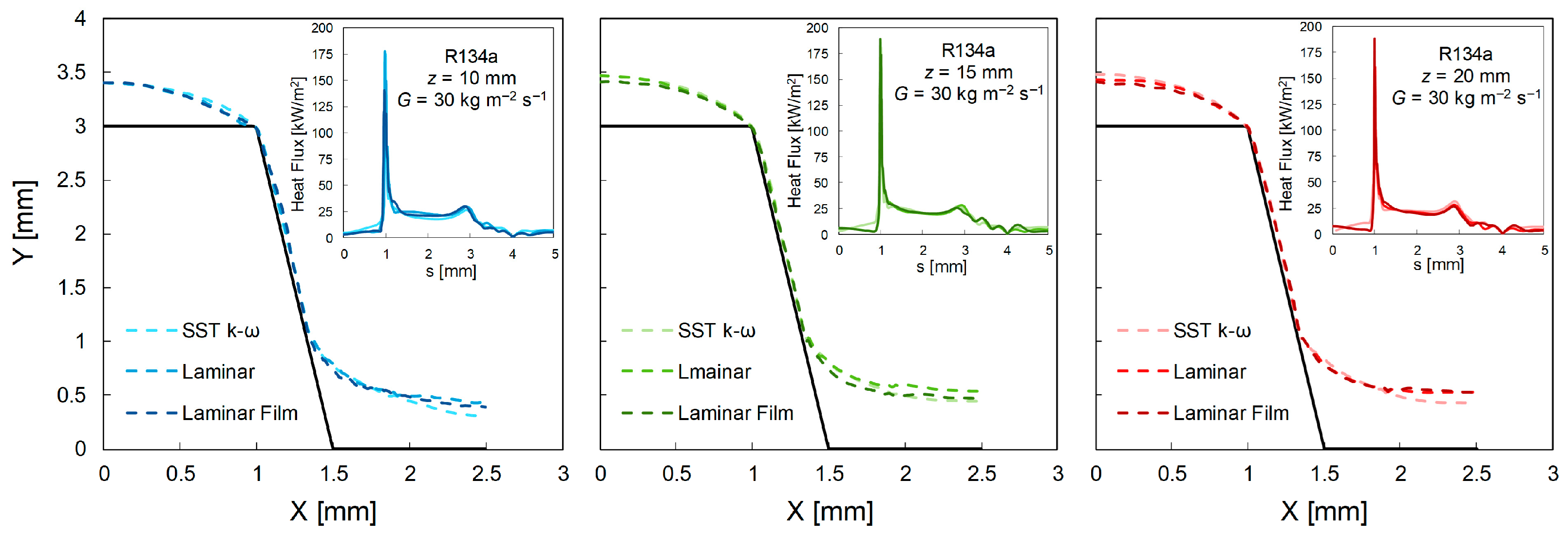
Although the condensate film Reynolds numbers investigated in the present work are consistent with predominantly laminar or, at most, transitional liquid film flow, the three-dimensional finned/grooved configuration may exhibit locally enhanced vapor-core turbulence and interfacial shear. For this reason, the baseline simulations were performed using the SST k-ω turbulence model with low-Re correction, which provides a robust closure for flows spanning laminar-to-transitional conditions and, importantly, strongly damps turbulent viscosity in near-wall/low-Re regions. In order to verify that the adoption of SST k-ω low-Re does not introduce spurious heat transfer enhancement within the thin liquid film, dedicated sensitivity analysis tests were carried out over the range of liquid film Reynolds numbers considered in the study. For each operating condition, three modeling approaches were compared: (a) a fully laminar formulation in both phases; (b) the SST k-ω model with low-Re correction, applied in both vapor and liquid phases (baseline case); and (c) the low-Re model with an additional user-defined function (UDF) enforcing zero turbulent viscosity in the liquid phase (i.e., setting the liquid-phase eddy viscosity μt,L = 0 while retaining turbulence modeling in the vapor phase).
Considering the condensation of R134a on the trapezoidal fin geometry in horizontal orientation at a mass flux of G = 5 and 30 kg m−2 s−1, the difference in the surface-area-weighted mean heat flux between the baseline SST low-Re and the fully laminar model was found to be very small, with a maximum deviation of 0.6% for G = 5 kg m−2 s−1 and 3.8% for G = 30 kg m−2 s−1 (Table A1). In addition, qualitative comparisons of local condensate thickness and local heat flux profiles at z = 10, 15, and 20 mm (reported in Figure A1 and Figure A2) show that the same trends are detected, regardless of the modeling option considered. Overall, these results indicate that the predicted condensation performance in the investigated range is weakly sensitive to the turbulence treatment of the liquid film, while the SST k-ω low-Re closure provides a convenient and consistent framework to handle vapor-side turbulence and interfacial shear effects across the full dataset.
Table A1.
Surface-area-weighted mean heat flux for condensation of R134a on the trapezoidal fin geometry in horizontal orientation at mass fluxes of G = 5 and 30 kg m−2 s−1. Relative deviations with respect to the SST k-ω low-Re model are also reported for the different turbulence treatments.
Figure A1.
Comparison of liquid film thickness (dotted lines) and heat flux distributions (solid line) obtained at 5 kg m−2 s−1 at three axial cross-sections (z = 10, 15, and 20 mm) of the horizontally oriented trapezoidal fin for three modeling approaches: SST k-ω with low-Re correction, fully laminar liquid and vapor phases, and a laminar liquid film model with turbulence resolved only in the vapor phase.
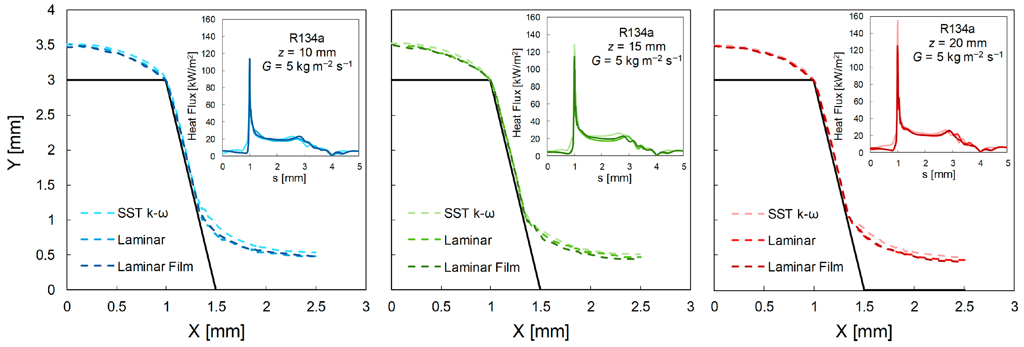
Figure A2.
Comparison of liquid film thickness (dotted lines) and heat flux (solid line) distributions obtained at 30 kg m−2 s−1 at three axial cross-sections (z = 10, 15, and 20 mm) of the horizontally oriented trapezoidal fin for three modeling approaches: SST k-ω with low-Re correction, fully laminar liquid and vapor phases, and a laminar liquid film model with turbulence resolved only in the vapor phase.
Appendix B. Mesh Sensitivity Analysis
A mesh sensitivity study was carried out to quantify the impact of spatial discretization on the main integral outcomes of the simulations. A representative case was selected (trapezoidal geometry, R134a), and three meshes were generated: a coarse grid with approximately 1.3 × 10⁶ elements, a medium grid with approximately 2.5 × 10⁶ elements, and a fine grid with approximately 5.0 × 10⁶ elements. The refinement strategy was designed to progressively improve the resolution of the near-wall region that hosts the condensate film: compared to the fine mesh, the medium mesh reduced the number of cells across the liquid-film boundary-layer region by approximately one third, whereas the coarse mesh reduced it by approximately two thirds. All physical models and numerical settings were kept identical across the three runs; only the mesh resolution was varied. As quantitative indicators, the surface-area-weighted mean heat flux over the entire heat transfer surface and the total condensate volume in the computational domain were evaluated. The results are reported in Table A2. The predicted mean heat flux increased from 14.7 kW m−2 (coarse) to 15.4 kW m−2 (medium) and 16.2 kW m−2 (fine). Compared to the fine grid, the deviation was 4.9% for the medium mesh and 9.2% for the coarse mesh. For the condensate volume, the medium and fine meshes provided nearly identical values (2.75 × 10⁻⁸ m3 vs. 2.77 × 10⁻⁸ m3, difference < 1%), whereas the coarse mesh predicted a substantially larger condensate volume (4.39 × 10⁻⁸ m3, deviation of approximately 60%). This discrepancy is attributed to insufficient resolution of the VOF interface and thin-film region in the coarse grid.
Based on these results, the fine mesh (approximately 5.0 × 10⁶ elements) was adopted for the full set of 3D simulations to ensure robust convergence and to reduce numerical diffusion at the vapor–liquid interface, while applying the same near-wall/interface refinement strategy consistently across the other geometries and operating points.
Table A2.
Mesh sensitivity study for condensation of R134a on the trapezoidal fin geometry, showing the variation in surface-area-weighted mean heat flux and total condensate volume as a function of the number of mesh elements.
Appendix C. Validation of Numerical Simulations Against Nusselt Theory
The Nusselt theory for film condensation [56] has been considered to validate the developed numerical model. The case study consists of a two-dimensional domain in which the fluid, in saturated vapor conditions, condenses (at near zero velocity) over a vertical surface having a uniform and constant temperature lower than the saturation temperature. According to the Nusselt theory, the thickness of the liquid film forming over a vertical plate can be calculated with the following relationship:
where is the liquid thickness, is the dynamic viscosity of the liquid, is the temperature of the wall upon which the vapor condenses, is gravity acceleration and is the coordinate along which the liquid film develops.
The laminar liquid film approach has been employed for turbulence modeling. It assumes laminar flow in the liquid phase and turbulent flow in the vapor phase. In this case, the standard low-Reynolds number formulation by Wilcox [58] is applied to the vapor phase, while a zero turbulent viscosity is imposed within the liquid phase. A blending function is used at the interface to transition between the two regions.
In Figure A3a, the geometry and the boundary conditions are presented. The geometry consists of a two-dimensional channel with a width of 1 m and a length of 105 mm. The rectangular section has been subdivided with a structured mesh consisting of 1.05 × 10⁵ elements. The static mesh is refined near the wall to ensure an adequate number of cells in the liquid film (10 cells at least) during condensation. Adiabatic parts are considered near the inlet and outlet of the domain. The wall where condensation occurs is maintained at a temperature of 10 K below the saturation temperature. A no-slip condition is set on the vertical plate. On the right side of the domain, slip and adiabaticity conditions are fixed. Velocity inlet is imposed at the top boundary, introducing saturated vapor at 40 °C, and the pressure outlet is applied at the bottom boundary. Gravity and surface tension effects are considered in the model.
Figure A3b shows an excellent agreement between the film thicknesses predicted analytically and those obtained from the computational simulations for all four refrigerants. The mean percentage error eR, the mean absolute percentage error eAB, and the standard deviation σN for each fluid are reported in Table A3. For the refrigerants R134a, R290, and R717, eAB remains below 3.5%, while for R245fa, it is 7.1%.
Figure A3.
Numerical model validation using the Nusselt [56] theory: (a) boundary conditions and (b) comparison between the theoretical and numerical LFT as a function of the condensate length Y.
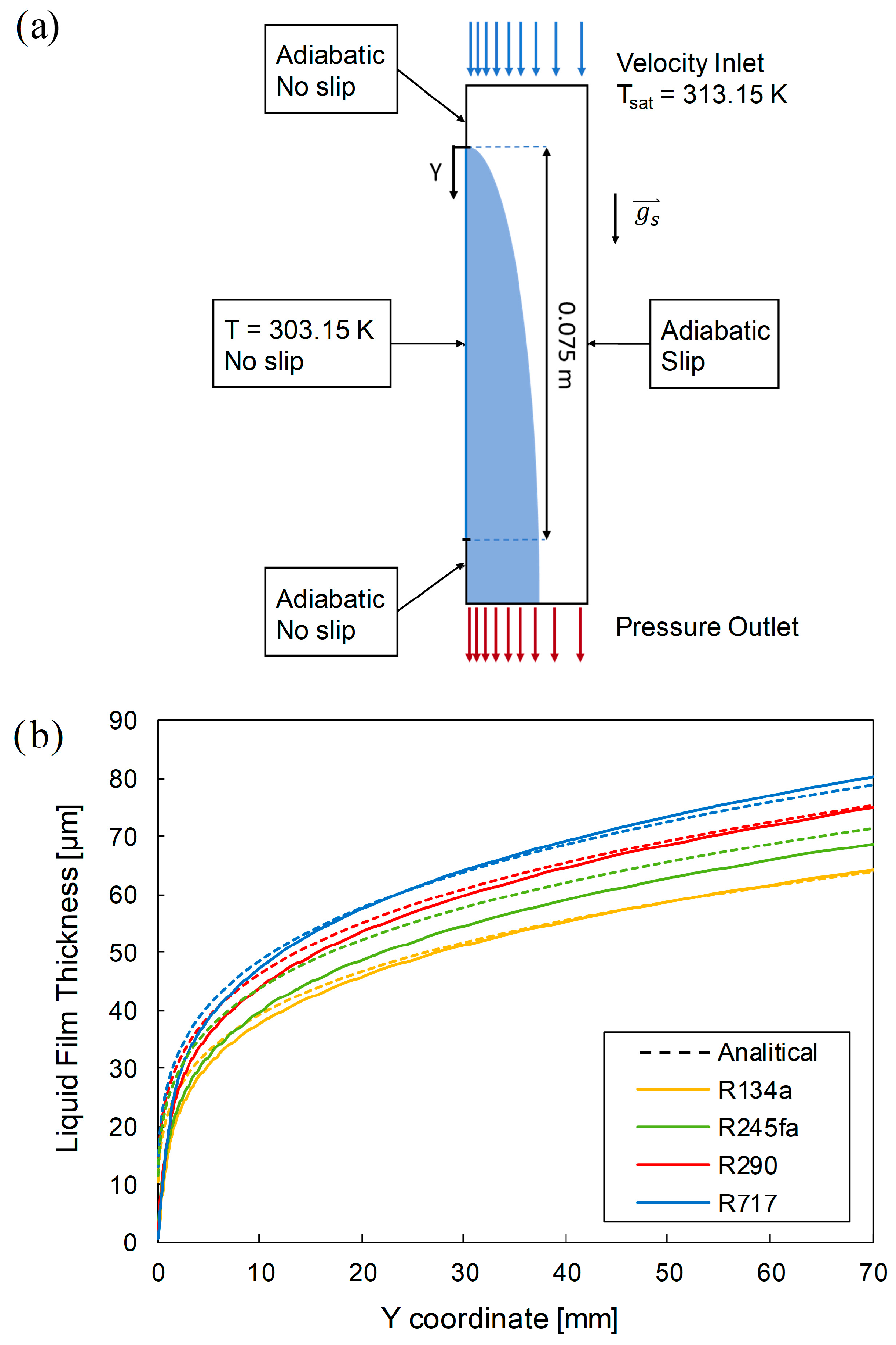
Table A3.
Mean percentage error eR, mean absolute percentage error eAB and standard deviation σN for R134a, R245fa, propane and ammonia.
References
- McLinden, M.O.; Brown, J.S.; Brignoli, R.; Kazakov, A.F.; Domanski, P.A. Limited Options for Low-Global-Warming-Potential Refrigerants. Nat. Commun. 2017, 8, 14476. [Google Scholar] [CrossRef] [Scilit]
- Abbatecola, A.; Tancon, M.; Fusina, L.; Bortolin, S.; Del Col, D. Investigation of Dropwise Condensation of Water at Atmospheric and Sub-Atmospheric Pressure through an Individual-Based Model. Appl. Therm. Eng. 2025, 276, 126892. [Google Scholar] [CrossRef] [Scilit]
- Faghri, A. Heat Pipe Science and Technology; CRC Press: Boca Raton, FL, USA, 1995. [Google Scholar]
- Chan, C.W.; Siqueiros, E.; Ling-Chin, J.; Royapoor, M.; Roskilly, A.P. Heat Utilisation Technologies: A Critical Review of Heat Pipes. Renew. Sustain. Energy Rev. 2015, 50, 615–627. [Google Scholar] [CrossRef] [Scilit]
- Robinson, A.J.; Colenbrander, J.; Deaville, T.; Durfee, J.; Kempers, R. A Wicked Heat Pipe Fabricated Using Metal Additive Manufacturing. Int. J. Thermofluids 2021, 12, 100117. [Google Scholar] [CrossRef] [Scilit]
- Ho, J.Y.; Leong, K.C. A Critical Review of Filmwise Natural and Forced Convection Condensation on Enhanced Surfaces. Appl. Therm. Eng. 2021, 186, 116437. [Google Scholar] [CrossRef] [Scilit]
- Al-Zaidi, A.H.; Mahmoud, M.M.; Karayiannis, T.G. Condensation Flow Patterns and Heat Transfer in Horizontal Microchannels. Exp. Therm. Fluid Sci. 2018, 90, 153–173. [Google Scholar] [CrossRef] [Scilit]
- Berto, A.; Azzolin, M.; Bortolin, S.; Miscevic, M.; Lavieille, P.; Del Col, D. Condensation Heat Transfer in Microgravity Conditions. NPJ Microgravity 2023, 9, 32. [Google Scholar] [CrossRef] [Scilit]
- Faghri, A.; Chow, L.C. Forced Condensation in a Tube with Suction at the Wall for Microgravitational Applications. J. Heat Transf. 1988, 110, 982–985. [Google Scholar] [CrossRef] [Scilit]
- Barakhovskaia, E.; Glushchuk, A.; Queeckers, P.; Iorio, C.S. Stabilisation of Condensate Flow from Curvilinear Surfaces by Means of Porous Media for Space Applications. Exp. Therm. Fluid Sci. 2021, 121, 110283. [Google Scholar] [CrossRef] [Scilit]
- Ge, M.; Wen, L.; Zhao, Z.; Diao, H.; Zhao, Y.; Wei, H.; Peng, Y.; Sato, T.; Wang, S. Study on the Condensation Characteristics of Air-Water Vapor Mixed Gas on Pin-Finned Surfaces. Int. Commun. Heat Mass Transf. 2025, 169, 109658. [Google Scholar] [CrossRef] [Scilit]
- Diani, A.; Brunello, P.; Rossetto, L. R513A Condensation Heat Transfer inside Tubes: Microfin Tube vs. Smooth Tube. Int. J. Heat Mass Transf. 2020, 152, 119472. [Google Scholar] [CrossRef] [Scilit]
- Azzolin, M.; Bortolin, S.; Magnabosco, A.; Cattelan, G.; Moro, L.; Bonesso, M.; Pepato, A.; Del Col, D. Local Heat Transfer Measurements during In-Tube Condensation of Refrigerants in a New Test Section Made by Additive Manufacturing. Appl. Therm. Eng. 2025, 274, 126689. [Google Scholar] [CrossRef] [Scilit]
- Zhu, Z.; Hu, Z.; Seet, H.L.; Liu, T.; Liao, W.; Ramamurty, U.; Ling Nai, S.M. Recent Progress on the Additive Manufacturing of Aluminum Alloys and Aluminum Matrix Composites: Microstructure, Properties, and Applications. Int. J. Mach. Tools Manuf. 2023, 190, 104047. [Google Scholar] [CrossRef] [Scilit]
- Nguyen, N.P.; Maghsoudi, E.; Roberts, S.N.; Hofmann, D.C.; Kwon, B. Understanding Heat Transfer and Flow Characteristics of Additively Manufactured Pin Fin Arrays through Laser-Induced Fluorescence and Particle Image Velocimetry. Int. J. Heat Mass Transf. 2024, 222, 125198. [Google Scholar] [CrossRef] [Scilit]
- El Achkar, G.; Septet, C.; Le Metayer, O.; Hugo, J.M. Experimental Thermohydraulic Characterisation of Flow Boiling and Condensation in Additive Manufactured Plate-Fin Heat Exchanger. Int. J. Heat Mass Transf. 2022, 199, 123465. [Google Scholar] [CrossRef] [Scilit]
- Lum, L.Y.X.; Leong, K.C.; Ho, J.Y. Optimizing Additively Manufactured Macro-Fin Structure Designs for Enhanced Pool Boiling of Dielectric Fluids. Int. J. Heat Mass Transf. 2024, 219, 124883. [Google Scholar] [CrossRef] [Scilit]
- Zhou, J.; Li, Q.; Chen, X. Micro Pin Fins with Topologically Optimized Configurations Enhance Flow Boiling Heat Transfer in Manifold Microchannel Heat Sinks. Int. J. Heat Mass Transf. 2023, 206, 123956. [Google Scholar] [CrossRef] [Scilit]
- Wan, W.; Deng, D.; Huang, Q.; Zeng, T.; Huang, Y. Experimental Study and Optimization of Pin Fin Shapes in Flow Boiling of Micro Pin Fin Heat Sinks. Appl. Therm. Eng. 2017, 114, 436–449. [Google Scholar] [CrossRef] [Scilit]
- Barakhovskaia, E.; Marchuk, I. Fin Shape Design for Stable Film-Wise Vapor Condensation in Microgravity. Microgravity Sci. Technol. 2022, 34, 8. [Google Scholar] [CrossRef] [Scilit]
- Glushchuk, A.; Minetti, C.; Machrafi, H.; Iorio, C.S. Experimental Investigation of Force Balance at Vapour Condensation on a Cylindrical Fin. Int. J. Heat Mass Transf. 2017, 108, 2130–2142. [Google Scholar] [CrossRef] [Scilit]
- Glushchuk, A.; Minetti, C.; Buffone, C. Fin Condensation in Variable Gravity Environment. Multiph. Sci. Technol. 2014, 26, 63–81. [Google Scholar] [CrossRef] [Scilit]
- Kedzierski, M.A.; Webb, R.L. Experimental Measurements of Condensation on Vertical Plates with Enhanced Fins. In American Society of Mechanical Engineers, Proceedings of the Boiling and Condensation in Heat Transfer, Boston, MA, USA, 1 January 1987; ASME: Boston, MA, USA, 1987. [Google Scholar]
- Ho, J.Y.; Wang, X.W.; Leong, K.C. Filmwise Condensation of Steam on Vertical Plates with Novel Pin Fin Arrays Produced by Selective Laser Melting. Int. J. Heat Mass Transf. 2018, 126, 652–666. [Google Scholar] [CrossRef] [Scilit]
- Ho, J.Y.; Leong, K.C.; Wong, T.N. Filmwise Condensation of Steam on Sinusoidal Pin Fin Arrays: Effects of Fin Height and Fin Pitch. Int. J. Heat Mass Transf. 2019, 130, 1004–1015. [Google Scholar] [CrossRef] [Scilit]
- Ho, J.Y.; Leong, K.C. Effect of Fin Pitch on the Filmwise Condensation of Steam on Three-Dimensional Conical Pin Fin Arrays: A Comparative Study. Int. J. Heat Mass Transf. 2020, 150, 119328. [Google Scholar] [CrossRef] [Scilit]
- Adamek, T.; Webb, R.L. Prediction of Film Condensation on Vertical Finned Plates and Tubes: A Model for the Drainage Channel. Int. J. Heat Mass Transf. 1990, 33, 1737–1749. [Google Scholar] [CrossRef] [Scilit]
- Marchuk, I.; Kabov, O.A. A Problem in the Calculus of Variations for Film Condensation on Curvilinear Fins. J. Eng. Thermophys. 2003, 12, 199–210. [Google Scholar]
- Marchuk, I.V.; Glushchuk, A.V.; Kabov, O.A. Vapor Condensation on Nonisothermal Curvilinear Fins. Tech. Phys. Lett. 2006, 32, 388–391. [Google Scholar] [CrossRef] [Scilit]
- Marchuk, I.; Lyulin, Y.; Kabov, O. Theoretical and Experimental Study of Convective Condensation inside a Circular Tube. Interfacial Phenom. Heat Transf. 2013, 1, 153–171. [Google Scholar] [CrossRef] [Scilit]
- Marchuk, I.V. Thermocapillary Deformation of a Horizontal Liquid Layer under Flash Local Surface Heating. J. Eng. Thermophys. 2015, 24, 381–385. [Google Scholar] [CrossRef] [Scilit]
- Wang, X.W.; Leong, K.C.; Wong, T.N. Numerical Analysis of Different Fluted Fins for Condensation on a Vertical Tube. Int. J. Therm. Sci. 2017, 122, 359–370. [Google Scholar] [CrossRef] [Scilit]
- Ho, J.Y.; Liu, P.; Leong, K.C.; Wong, T.N.; Miljkovic, N. A Theoretical Analysis and Parametric Study of Filmwise Condensation on Three-Dimensional Pin Fins. Int. J. Heat Mass Transf. 2021, 171, 121092. [Google Scholar] [CrossRef] [Scilit]
- Kedzierski, M.A.; Carr, M.A.; Brown, J.S. Measurement and Prediction of Vapor-Space Condensation of Refrigerants on Trapezoidal-Finned and Turbo-c Geometries. J. Enhanc. Heat Transf. 2013, 20, 59–71. [Google Scholar] [CrossRef] [Scilit]
- Rose, J.W. An Approximate Equation for the Vapour-Side Heat-Transfer Coefficient for Condensation on Low-Finned Tubes. Int. J. Heat Mass Transf. 1994, 37, 865–875. [Google Scholar] [CrossRef] [Scilit]
- Zanetti, E.; Berto, A.; Bortolin, S.; Magnini, M.; Del Col, D. Annular Two-Phase Flow in a Small Diameter Tube: OpenFOAM Simulations with Turbulence Damping vs Optical Measurements. Int. J. Thermofluids 2024, 24, 100871. [Google Scholar] [CrossRef] [Scilit]
- Krishna, K.V.; Pandey, V.; Maiya, M.P. Topology Optimized Fin Structures for Performance Enhancement of Metal Hydride Reactors. Int. J. Hydrogen Energy 2024, 60, 491–502. [Google Scholar] [CrossRef] [Scilit]
- Chen, Y.; Liu, Y.; Zeng, L.; Cui, W.; Xie, J. A Novel Topology Optimization of Fin Structure in Shell-Tube Phase Change Accumulator Considering the Double Objective Functions and Natural Convection. J. Energy Storage 2024, 80, 110327. [Google Scholar] [CrossRef] [Scilit]
- Hirt, C.W.; Nichols, B.D. Volume of Fluid (VOF) Method for the Dynamics of Free Boundaries. J. Comput. Phys. 1981, 39, 201–225. [Google Scholar] [CrossRef] [Scilit]
- Da Riva, E.; Del Col, D. Effect of Gravity during Condensation of R134a in a Circular Minichannel: VOF Simulation of Annular Condensation. Microgravity Sci. Technol. 2011, 23, 87–97. [Google Scholar] [CrossRef] [Scilit]
- Lee, W.H. A Pressure Iteration Scheme for Two-Phase Flow Modeling. In Multiphase Transport Fundamentals, Reactor Safety, Applications; Hemisphere: Washington, DC, USA, 1980; Volume 1. [Google Scholar]
- Bortolin, S.; Da Riva, E.; Del Col, D. Condensation in a Square Minichannel: Application of the VOF Method. Heat Transf. Eng. 2014, 35, 193–203. [Google Scholar] [CrossRef] [Scilit]
- Toninelli, P.; Bortolin, S.; Azzolin, M.; Col, D. Del Visualization and Numerical Simulations of Condensing Flow in Small Diameter Channels. Heat Transf. Eng. 2019, 40, 802–817. [Google Scholar] [CrossRef] [Scilit]
- Lemmon, E.W.; Bell, I.H.; Huber, M.L.; McLinden, M.O. NIST Standard Reference Database 23: Reference Fluid Thermodynamic and Transport Properties-REFPROP, Version 10.0; National Institute of Standards and Technology: Gaithersburg, MD, USA, 2018. [Google Scholar]
- Brackbill, J.U.; Kothe, D.B.; Zemach, C.A. Continuum Method for Modeling Surface Tension. J. Comput. Phys. 1992, 100, 335–354. [Google Scholar] [CrossRef] [Scilit]
- Muzaferija, S.; Peric, M.; Sames, P.; Schellin, T. A Two-Fluid Navier–Stokes Solver to Simulate Water Entry. In Proceedings of the 22nd Symposium on Naval Hydrodynamics, Washington, DC, USA, 9–14 August 1998. [Google Scholar]
- ANSYS, Inc. ANSYS Fluent 13 Theory Guide 2010; ANSYS, Inc.: Canonsburg, PA, USA, 2010. [Google Scholar]
- Patankar, S.V. Numerical Heat Transfer and Fluid Flow; Hemisphere: New York, NY, USA, 1980. [Google Scholar]
- Van Leer, B. Toward the Ultimate Conservative Difference Scheme. V. A Second Order Sequel to Godunov’s Method. J. Comput. Phys. 1979, 32, 101–136. [Google Scholar] [CrossRef] [Scilit]
- Da Riva, E.; Del Col, D.; Garimella, S.V.; Cavallini, A. The Importance of Turbulence during Condensation in a Horizontal Circular Minichannel. Int. J. Heat Mass Transf. 2012, 55, 3470–3481. [Google Scholar] [CrossRef] [Scilit]
- Menter, F.R. Two-Equation Eddy-Viscosity Turbulence Models for Engineering Applications. AIAA J. 1994, 32, 1598–1605. [Google Scholar] [CrossRef] [Scilit]
- Berman, L.D. On the Effect of Molecular-Kinetic Resistance upon Heat Transfer with Condensation. Int. J. Heat Mass Transfer 1967, 10, 1463. [Google Scholar] [CrossRef] [Scilit]
- McNaught, J.M.; Butterworth, D. Film Condensation of Pure Vapor—Interfacial (Molecular Kinetic) Resistance. In Heat Exchanger Design Handbook; Hewitt, G.F., Ed.; Begell House: New York, NY, USA, 2002; p. 14. [Google Scholar]
- Wang, H.S.; Rose, J.W. Effect of Interphase Matter Transfer on Condensation on Low-Finned Tubes—A Theoretical Investigation. Int. J. Heat Mass Transf. 2004, 47, 179–184. [Google Scholar] [CrossRef] [Scilit]
- Nebuloni, S.; Thome, J.R. Numerical Modeling of Laminar Annular Film Condensation for Different Channel Shapes. Int. J. Heat Mass Transf. 2010, 53, 2615–2627. [Google Scholar] [CrossRef] [Scilit]
- Nusselt, W. Die Oberflächenkondensation Des Wasserdampfes. Z. Des Vereines Dtsch. Ingenieure 1916, 60, 541–546. [Google Scholar]
- TDS-HFE-7100-Heat-Transfer. Available online: https://it.scribd.com/document/49607345/TDS-HFE-7100-Heat-Transfer (accessed on 19 November 2025).
- Wilcox, D.C. Turbulence Modeling for CFD, 2nd ed.; DCW Industries, Inc.: La Canãda, CA, USA, 1998. [Google Scholar]
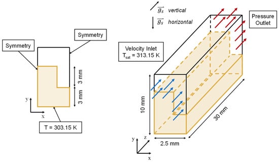
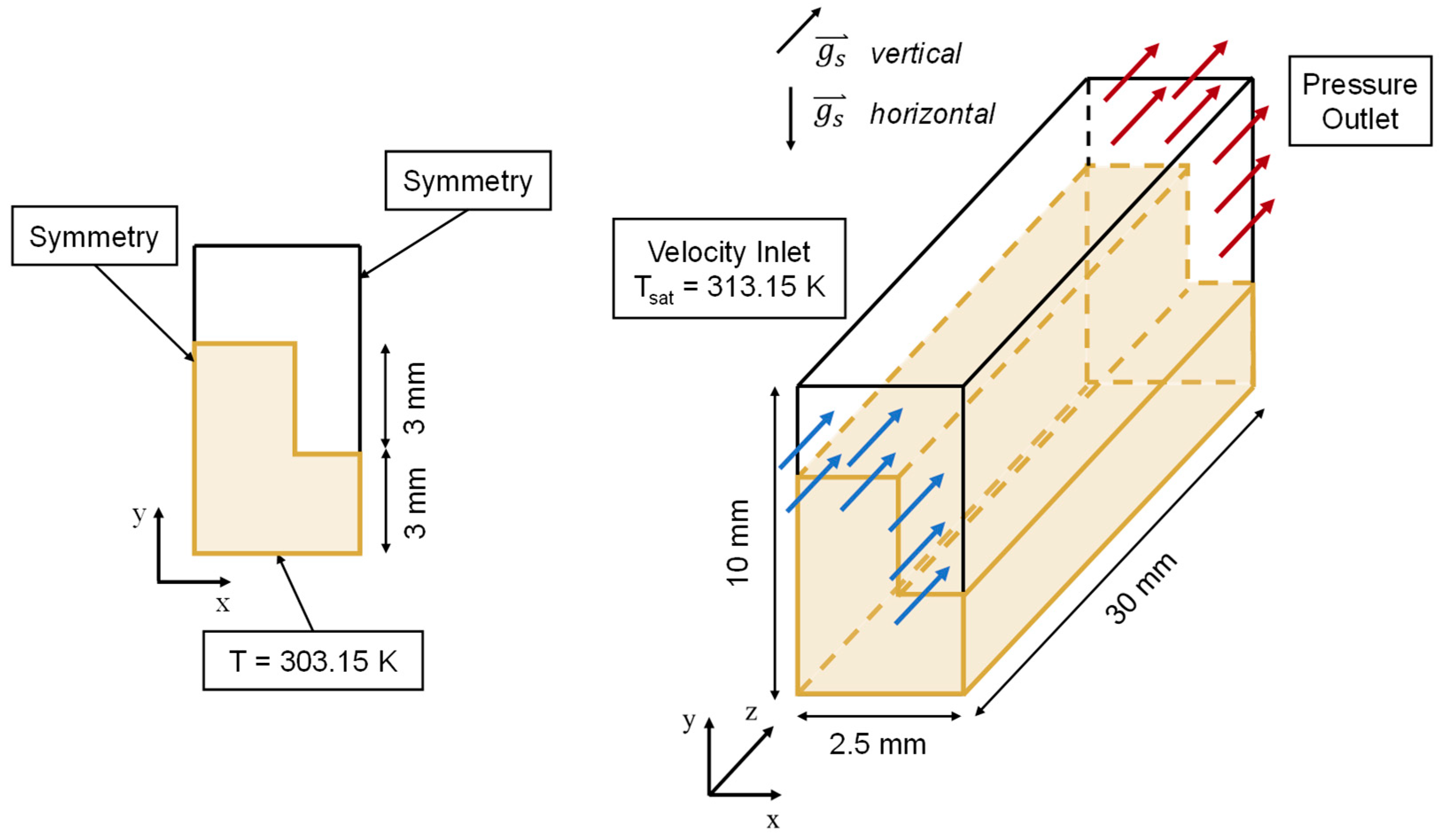
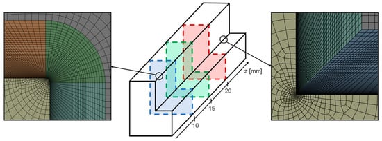
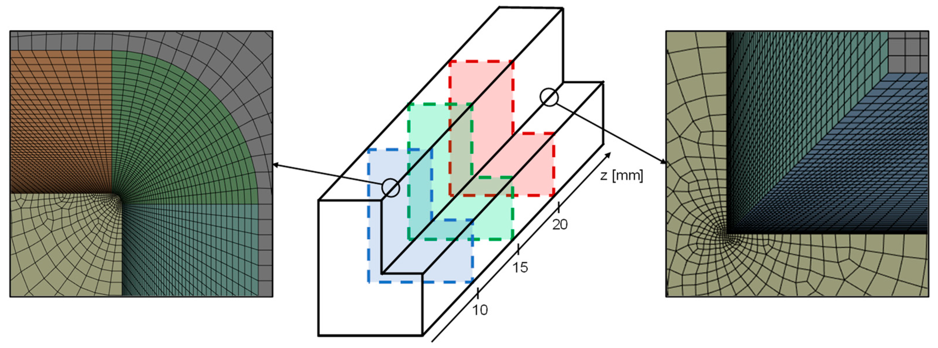
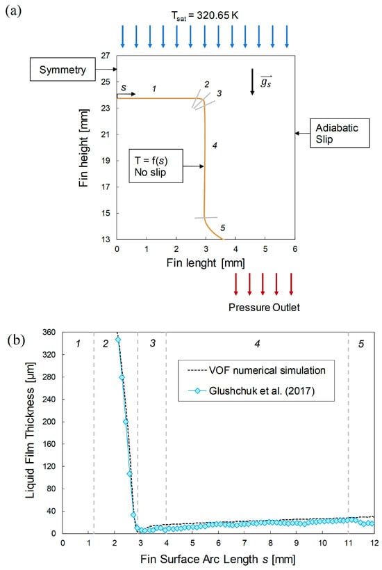
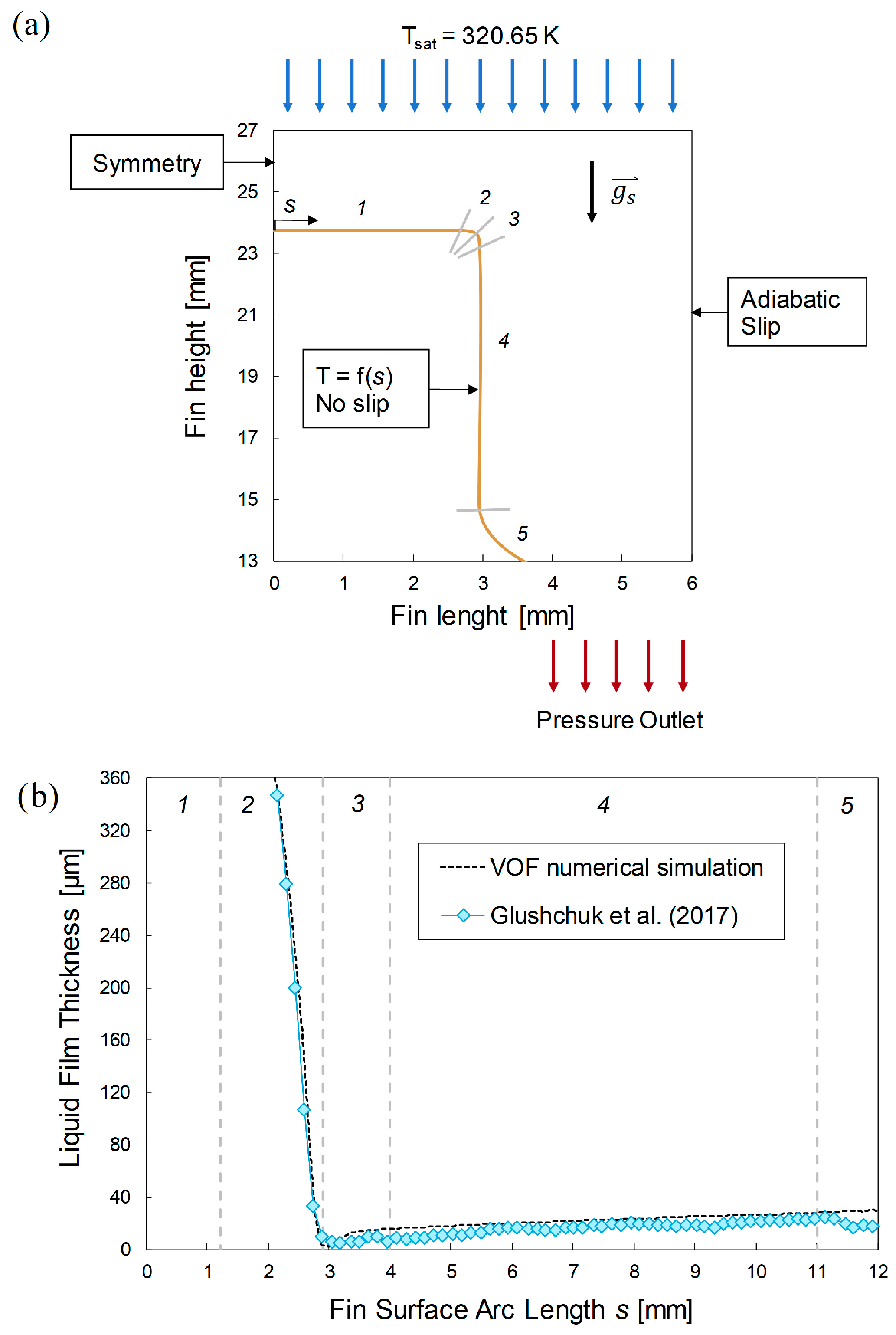
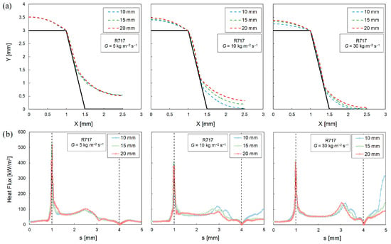
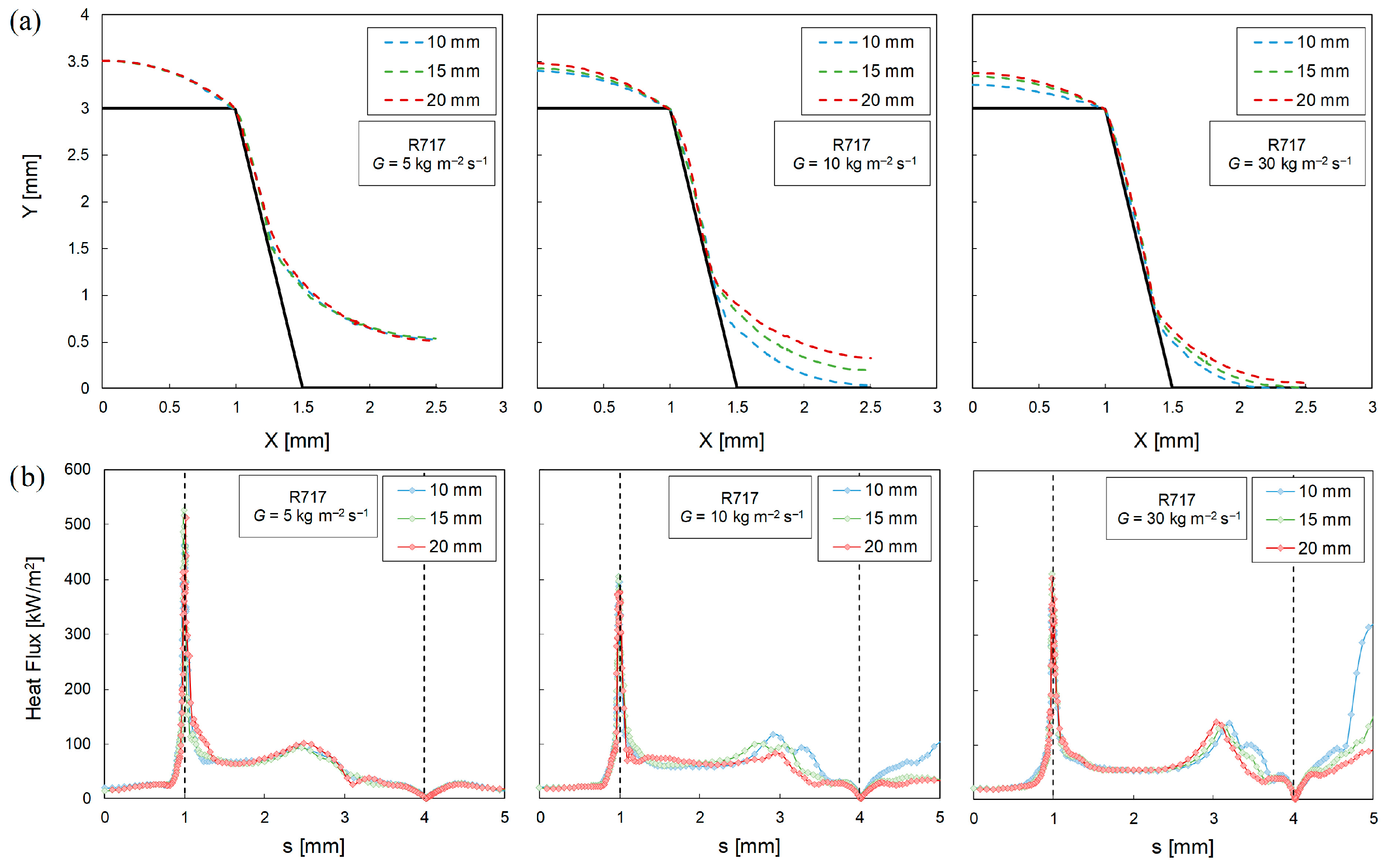
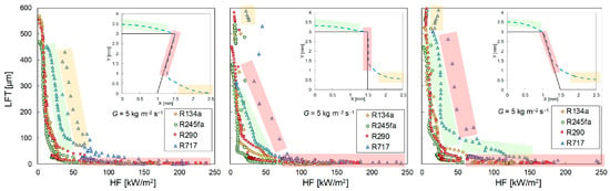
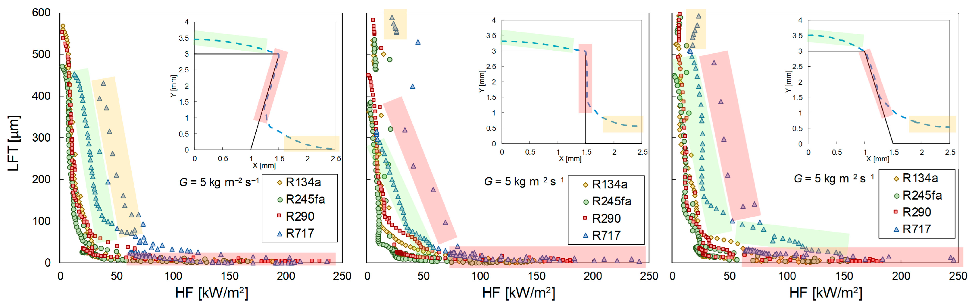
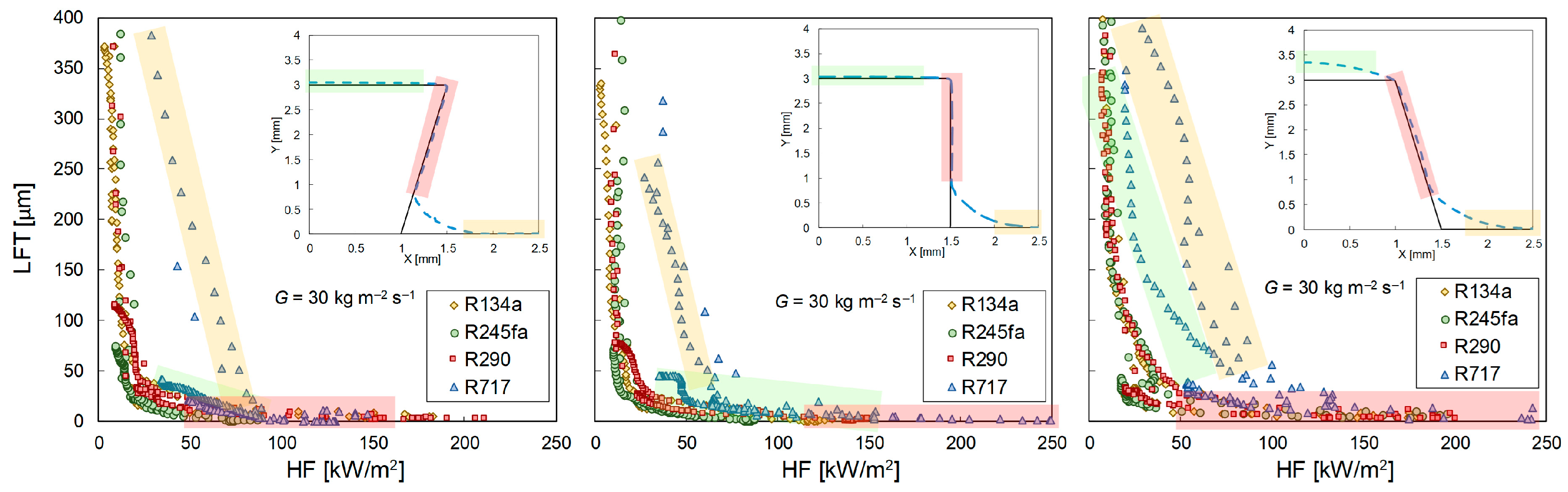
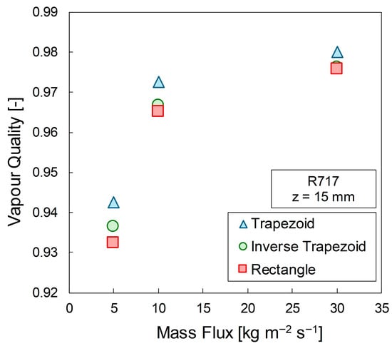
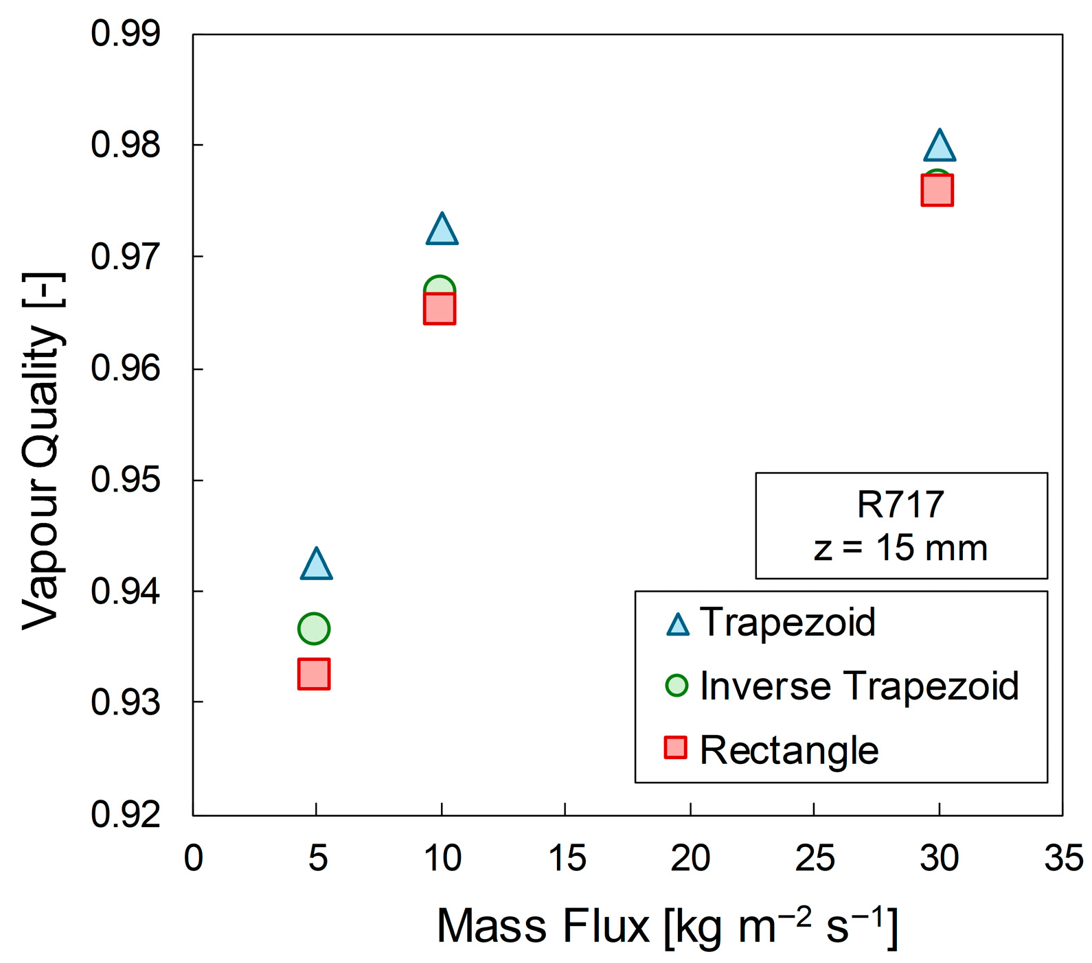
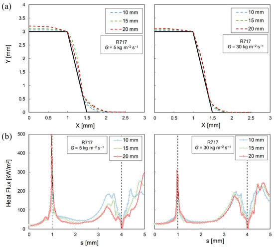
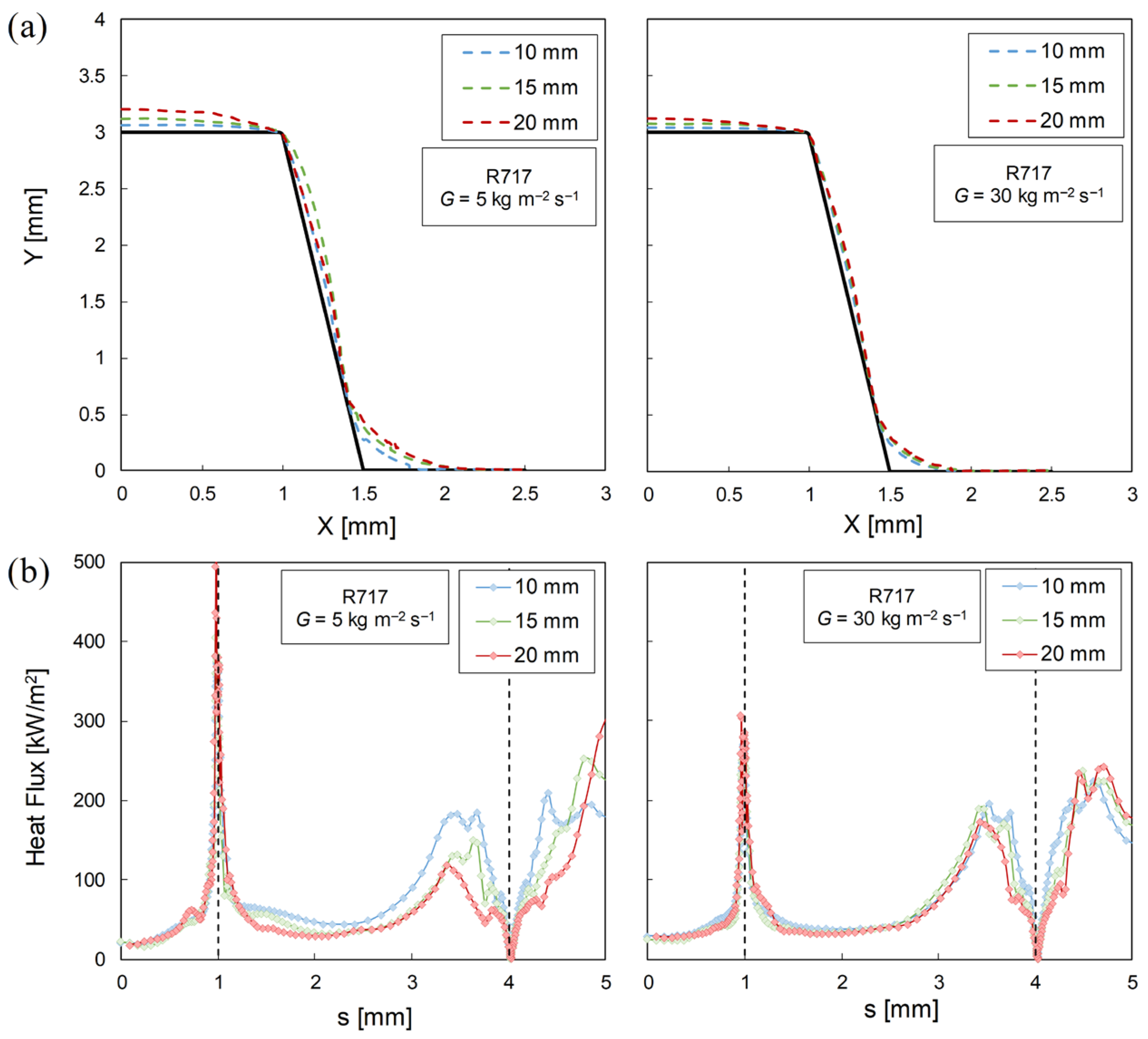
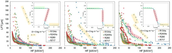
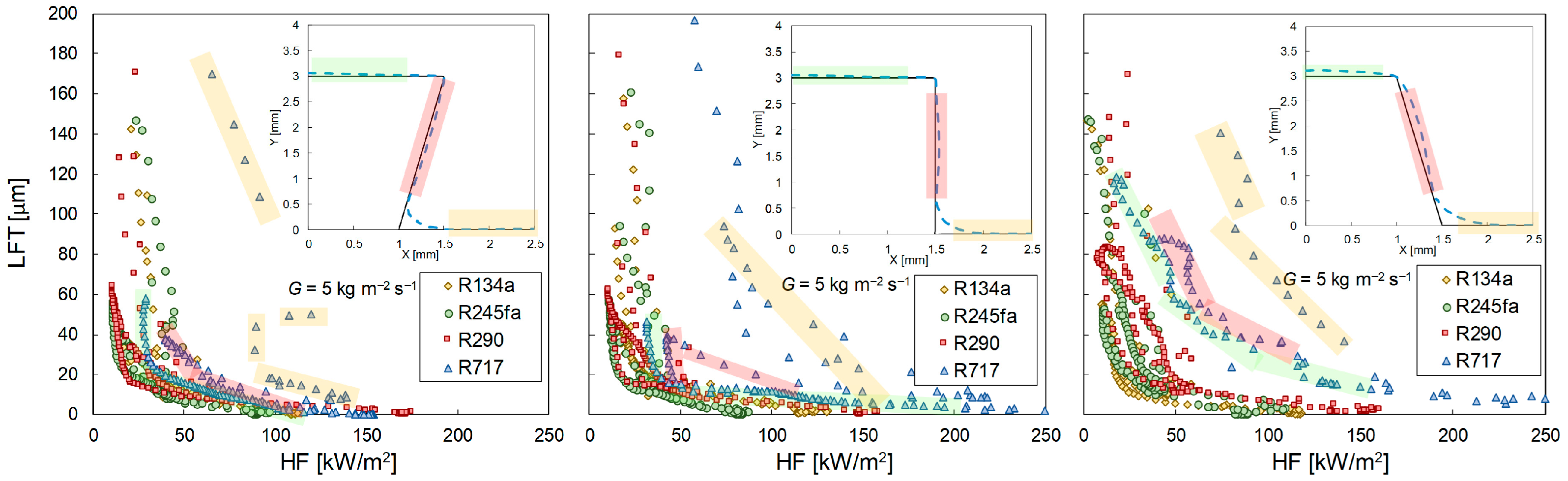
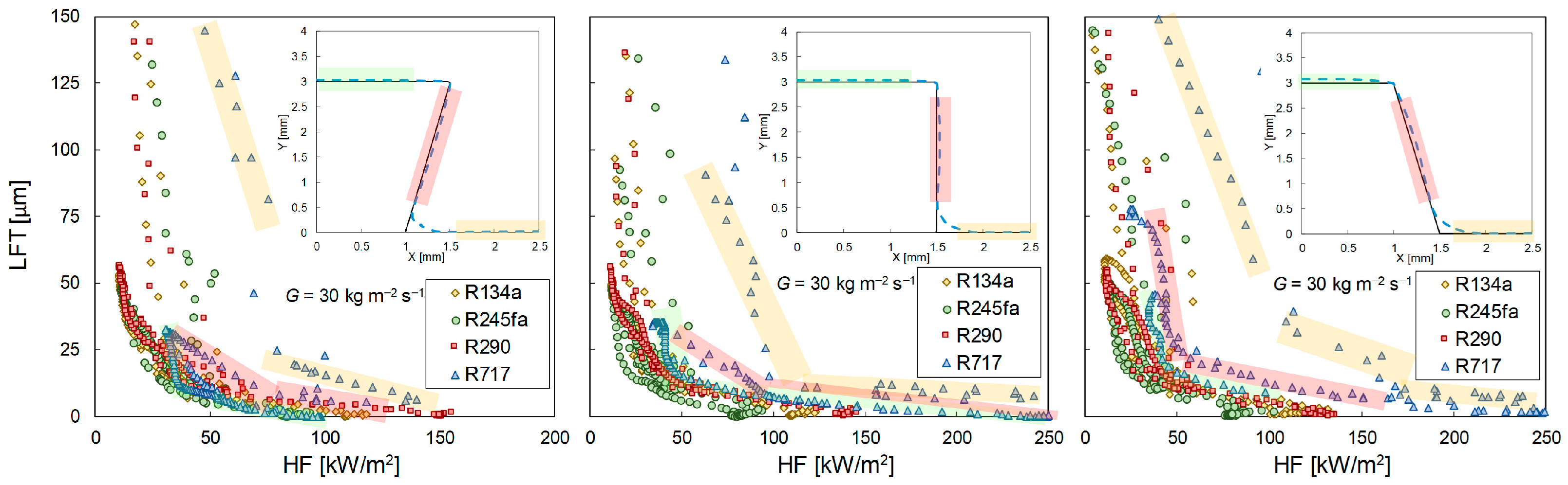
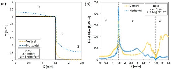
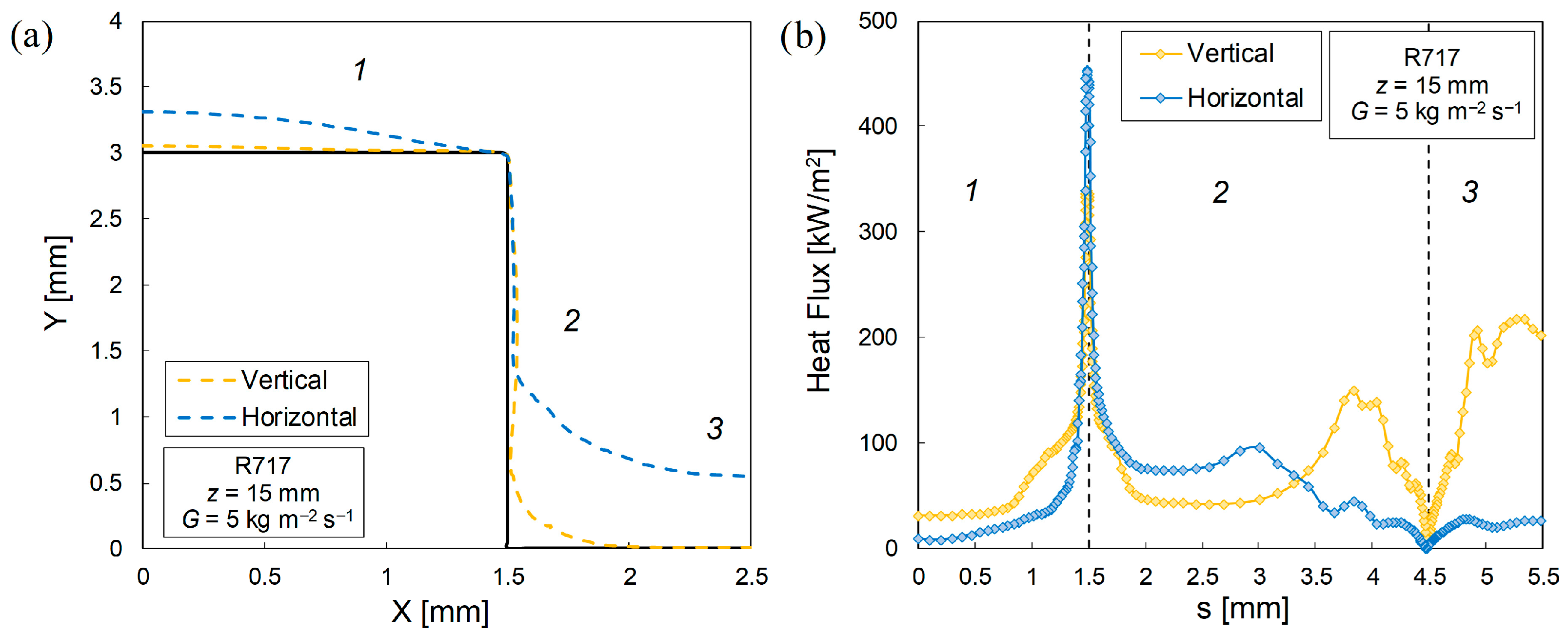
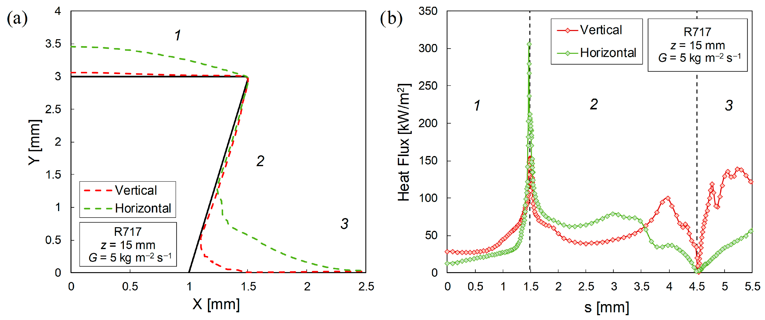

Disclaimer/Publisher’s Note: The statements, opinions and data contained in all publications are solely those of the individual author(s) and contributor(s) and not of MDPI and/or the editor(s). MDPI and/or the editor(s) disclaim responsibility for any injury to people or property resulting from any ideas, methods, instructions or products referred to in the content. |
© 2026 by the authors. Licensee MDPI, Basel, Switzerland. This article is an open access article distributed under the terms and conditions of the Creative Commons Attribution (CC BY) license.