


Abstract
To clarify the electrothermal failure of fixed contacts in a 363 kV three-phase five-column disconnector, field inspection, circuit-resistance tests, contact-mechanical modeling, finger-level resistance calculation, and electrothermal simulation were combined. The fault side had approximately 10 mm settlement and 51 mm horizontal displacement. Unserved contacts remained at 81–83 μΩ, whereas field-served contacts showed displacement-sensitive, non-monotonic resistance changes. A finite element model of 24 contact fingers with assembly-induced prestress was developed. Contact pressures were calculated under normal, settlement, and combined settlement—horizontal displacement conditions. Normal force was integrated over each contact area, and zero pressure denoted contact loss. The force, contact length, and equivalent contact width were used in a cylinder-on-flat model to calculate finger resistance. These resistances were connected in parallel and calibrated against the measured normal-state resistance of 83.57 μΩ. Settlement redistributed load from lower to upper fingers, while further horizontal displacement concentrated contact on one side; eastward displacement caused all bottom-row fingers to lose contact. Electrothermal simulation showed little temperature change while most fingers remained in contact, but temperatures exceeded 130 °C after bottom-row contact loss. Thus, total resistance can conceal local degradation, while load redistribution and current concentration increase Joule heating in remaining paths and explain burnout.
1. Introduction
Stable contact in a closed high-voltage disconnector is essential for current transfer and thermal safety. For outdoor equipment with independently supported posts, foundation settlement and horizontal displacement can alter contact alignment, insertion depth, and finger compression. These changes are especially important in multi-finger contacts, where individual branches may experience opposite load changes. Recent studies have estimated contact temperature [1], incorporated environmental effects [2], and diagnosed thermal faults [3], but the link between support movement and non-uniform electrical degradation remains unclear.
Experimental and model-based diagnosis has clarified how electrical losses and boundary conditions affect equipment temperature. Finite element predictions have been compared with double-break circuit-breaker tests [4], while GIS studies have used radial and transient temperature responses to identify conductor overheating [5,6]. Mechanical diagnosis has advanced through digital-twin analysis of electrodynamic forces [7], motor-power and image-based classification [8], and vibration-feature recognition [9]. These methods identify equipment-level abnormalities, but they do not explain how a specific foundation deviation redistributes load among contact fingers or produces an ambiguous circuit-resistance signature.
Contact-mechanics studies provide the physical basis for this problem. Multiphysics models have related contact force to potential and temperature fields [10], and spring-supported connectors have shown that changes in mechanical support can alter resistance and heating [11]. Rough-surface and multipoint models show that the effective conducting area, asperity deformation, and interacting conducting spots determine constriction resistance [12,13,14,15,16,17]. Thus, neither nominal overlap nor total contact force alone can fully describe interfacial conduction.
Surface condition introduces additional variability. Silver coating architecture, wear, and delamination affect electrical endurance [18,19,20], while current-assisted wear, thermal-mechanical stress, and transfer films alter the interface during service [21,22,23,24]. Interfacial breakdown can also redistribute current near a contact boundary [25]. Long-serving, oxidized contacts may therefore respond more strongly to pressure changes than new contacts. However, coating degradation and foundation-induced load redistribution have not been connected through finger-level resistance and temperature analysis for outdoor disconnectors.
The unresolved issue is how vertical settlement and horizontal displacement propagate through a 24-finger contact. The fingers are mechanically coupled but electrically parallel, so support movement first changes the mechanical deformation state and redistributes contact pressure, potentially causing one-sided contact or complete separation of individual fingers. As conducting spots are lost, the current is carried by the remaining fingers, and local Joule heating can intensify even when the total circuit resistance changes only moderately. Consequently, this degradation cannot be characterized by total resistance alone; it must be analyzed through the coupled chain of deformation, local contact failure, current redistribution, and local overheating. To this end, this paper examines a 363 kV three-phase five-column disconnector burnout accident by combining fracture evidence, controlled circuit-resistance tests, contact-mechanical modeling, and electrothermal simulation. Field damage and material tests are used to infer the failure sequence, while a finite element model with assembly-induced prestress resolves finger-level force, contact area, resistance, and heating under different displacement conditions.
2. Fault Description and Sequence of Events
2.1. Equipment Structure and Fault Description
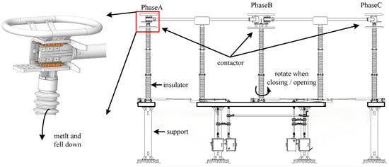
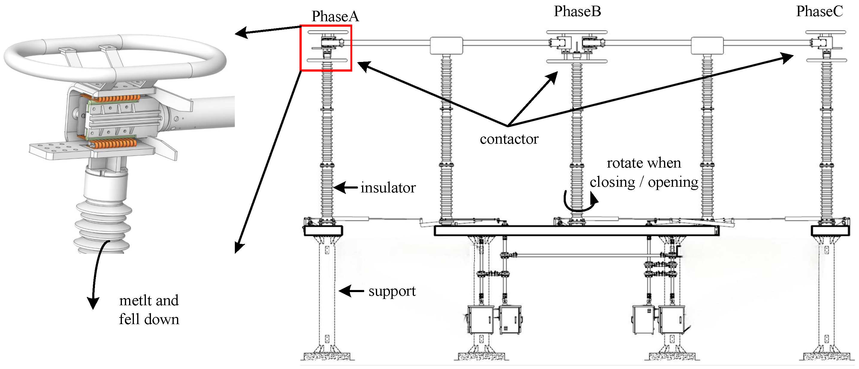
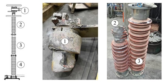
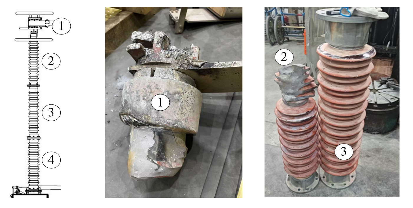
The faulty equipment was a 363 kV AC disconnector on the medium-voltage side of the main transformer in a 750 kV substation, which had been in operation for 16 years. The equipment uses a three-phase five-column horizontal rotating structure. Its main components and field installation are shown in Figure 1. When closing, the moving contact enters the fixed contact and then rotates around its own axis, being clamped by the elastic contact fingers on both sides of the fixed contact to form a conductive connection. When the fault occurred, the current was 1799.17 A and the maximum current recorded during the fault was 2731.29 A. Post-accident inspection revealed that the fixed contact on one side of phase A was severely burned and had fallen off from the top insulator. The conductive rod was burned through, and part of the shed on the top insulator was damaged and broken. The field damage is shown in Figure 2, where ① indicates the damaged contact, ② the top post insulator (partially damaged), and ③ the middle supporting insulator (intact). The other side of the same phase and phases B and C showed no similar damage.
Figure 1.
Structure of the 363 kV three-phase five-column AC disconnector.
Figure 2.
Burnout of the fixed contact and damage to the post insulator.
The burning damage of the fixed contact and the fracture of the post insulator were observed simultaneously, so the sequence of these two events must be determined. For this purpose, the intact lower post insulator was examined, and the following findings were obtained: (i) the dimensions of the insulator agree with the design drawings, with no obvious deformation; (ii) ultrasonic testing carried out in accordance with Q/GDW 407-2010 revealed no internal defects in the insulator; (iii) in torsion tests at 2 kN·m performed in accordance with GB/T 8287.1-2008, no cracking occurred, and the insulator withstood the specified 24 kN bending load without fracture. This largely excludes the possibility that the insulator body fractured under the transverse force caused by strong winds; (iv) the bulk density and open porosity of the main cross-section were analyzed in accordance with GB/T 8411.2-2008, and both meet the standard requirements; and (v) a porosity test carried out in accordance with GB/T 772-2005 showed no dye penetration at the section, indicating that no interconnected pores or cracks are present [26,27,28,29].
Further examination of the fracture morphology showed that the upper post insulator in the faulted phase fractured and separated between the second and third sheds from its upper end, with damage extending to the ninth shed. The overall fracture surface consisted of vertical and horizontal fracture planes according to their orientation. The former exhibited pronounced ablation and adhered spatter of molten metals, including aluminum, whereas the latter showed no obvious burning marks, and the adhered spatter decreased progressively in one direction. This difference indicates that the vertical fracture occurred first; the crack subsequently propagated horizontally under the combined effects of thermal shock and external forces, ultimately causing fracture. This morphology differs markedly from brittle fracture caused solely by external force. Accordingly, the observed morphology is consistent with the characteristic thermal-shock-induced shattering of porcelain. Combined with the preceding test results and fracture morphology, the upper post insulator is considered to have fractured after ignition of the contact fault.
After the accident, the foundation on the fault side was re-measured. The fixed contact post had settled by about 10 mm, accompanied by about 51 mm horizontal displacement. The fixed contact is supported by an independent side column, and foundation displacement can be directly transmitted to the contact mating part, changing the relative height, insertion position, and insertion depth of each contact finger. Thus, foundation displacement became the main working condition variable for subsequent circuit resistance tests and contact mechanics analysis.
2.2. Circuit Resistance Test Under Foundation Displacement
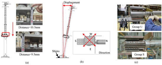
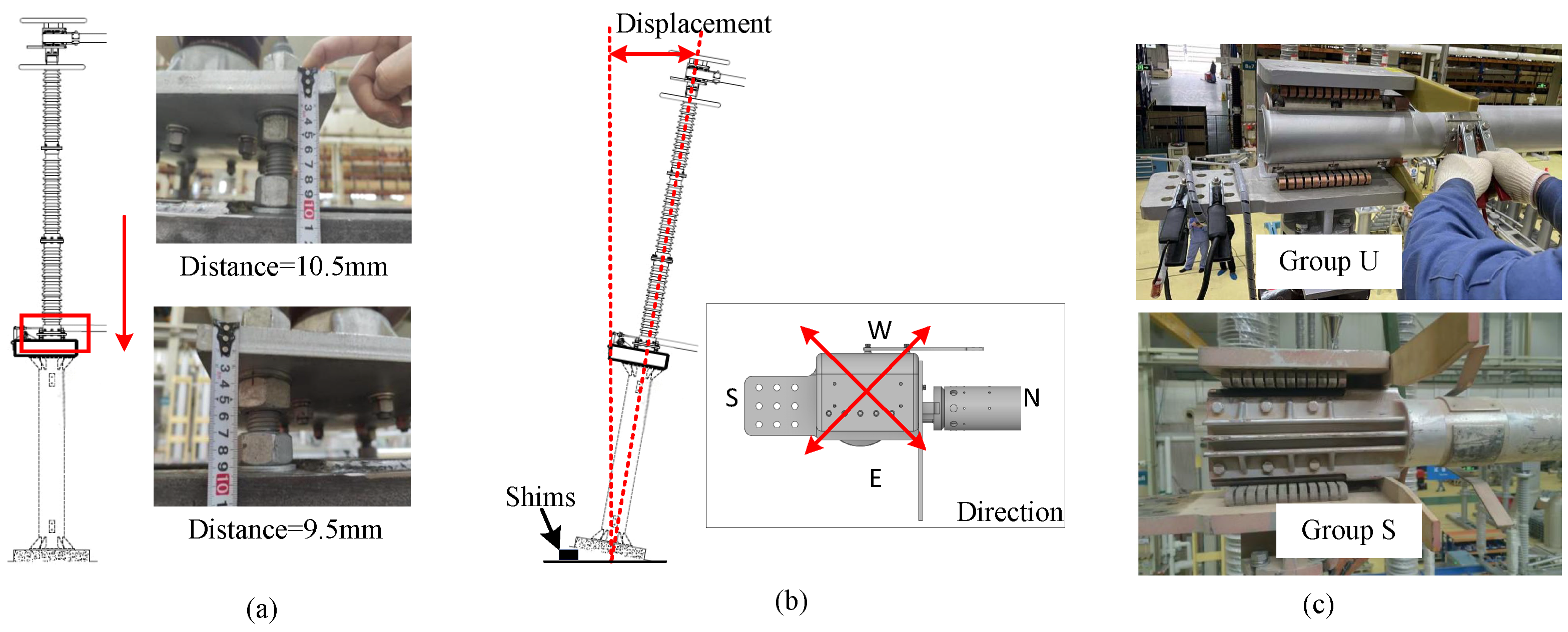
The foundation displacement test device and measurement method are shown in Figure 3:
Figure 3.
Experimental setup and displacement adjustment for foundation displacement—circuit resistance tests. (a) Settlement adjustment method; arrows indicate the settlement direction. (b) Horizontal displacement adjustment method; N, S, E, and W denote north, south, east, and west, corresponding to the NE, NW, SE, and SW directions. (c) Two sets of contacts.
- (i)
- Determination of the reference position: After the disconnector is closed normally, the vertical distance between the adjustment plate beneath the fixed-contact post insulator and the support is measured and recorded as the zero-settlement height. A plumb line is suspended above the fixed contact as a reference, and the corresponding point on the contact surface is marked. The contact is considered to be in the zero-displacement state when the plumb line aligns with this point.
- (ii)
- Determination of settlement: The four adjustment-plate nuts beneath the insulators on the fixed-contact side are adjusted simultaneously while the plumb line above the contact is kept aligned with the reference point. The settlement is then determined by measuring the vertical distance between the adjustment plate and the support.
- (iii)
- Determination of horizontal displacement: Steel plates are placed beneath the steel supports on the fixed-contact side to displace that side by 50–80 mm toward the northeast. The horizontal displacement is determined by measuring the distance between the plumb line and the observation point.
Two sets of contacts (shown in Figure 3c) of the same structure were selected for testing. The unserved group consisted of spare contacts that had not been put into field operation, with an intact silver coating on the surface. The field-served group consisted of contacts of the same model that had been removed after 16 years of continuous operation, with a blackened surface, obvious oxidation and contamination, and an essentially invisible original silver coating. For subsequent comparison, they are denoted as group U and group S, respectively. Apart from different service states, the two groups of contacts also differ in surface condition and mechanical properties. Therefore, the following mainly compares their overall electrical responses under the same displacement conditions.
During the resistance measurement, one clamp was connected to the terminal plate of the fixed contact and the other to the connecting rod of the fixed contact (Figure 3c). The measurement resolution was 0.01 μΩ, and the measurement current was 100–105 A. Each resistance value was measured three times. Results show that the contact resistance of Group U remained within the range of 81–83 μΩ under the normal position, 10 mm foundation settlement, and 10 mm settlement combined with a 50–80 mm horizontal displacement. This indicates that foundation settlement and horizontal displacement have only a minimal effect on the contact resistance of new contacts.
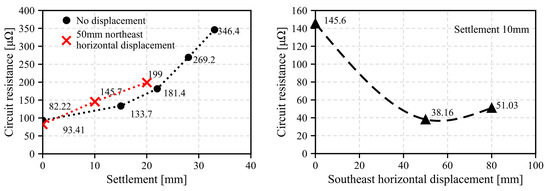
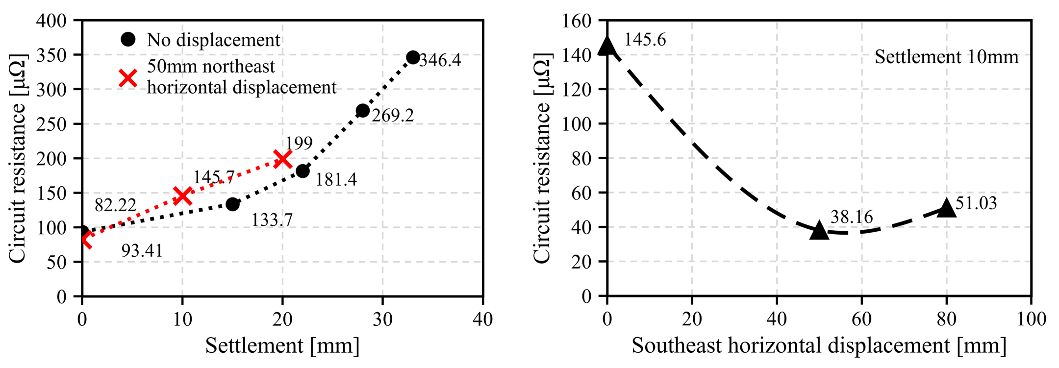
Figure 4 presents the circuit resistance of Group S under different foundation displacement conditions. As shown in Figure 4a, the circuit resistance of the no-horizontal-displacement series shows a pronounced nonlinear (superlinear) increase with settlement, from 82.22 μΩ at 0 mm to 356.4 μΩ at approximately 34 mm (with intermediate values of 93.41, 133.7, 181.4, and 269.2 μΩ). By contrast, under a constant 50 mm northeast horizontal displacement, the circuit resistance increases approximately linearly with settlement, reaching 82.22, 145.7, and 199 μΩ at settlements of 0, 10, and 20 mm, respectively. Figure 4b shows the circuit resistance for a fixed vertical settlement of 10 mm and varying horizontal displacement toward the southeast. As the horizontal displacement increased from 0 to 50 mm, the circuit resistance decreased from 145.6 to 38.16 μΩ. When the displacement was further increased to 80 mm, the resistance rose to 51.03 μΩ, exhibiting a non-monotonic variation.
Figure 4.
Circuit resistance under different foundation displacement conditions. (a) Different settlement amounts at 50 mm horizontal displacement; (b) different horizontal displacements at 10 mm settlement.
These results indicate that vertical settlement and horizontal displacement affect the electrical conduction behavior of the contacts in different ways. With the horizontal displacement held constant, increasing the settlement led mainly to a continuous increase in circuit resistance. By contrast, with the settlement held constant, changing the horizontal position altered the compression of individual contact fingers, causing the total circuit resistance to first decrease and then increase. This behavior should be analyzed further in relation to the contact-pressure distribution among the contact fingers, as the local contact condition cannot be determined from the total circuit resistance alone.
3. Contact Characteristics of Multiple Contact Fingers Under Foundation Displacement
3.1. Simulation Model
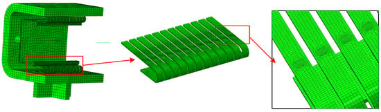
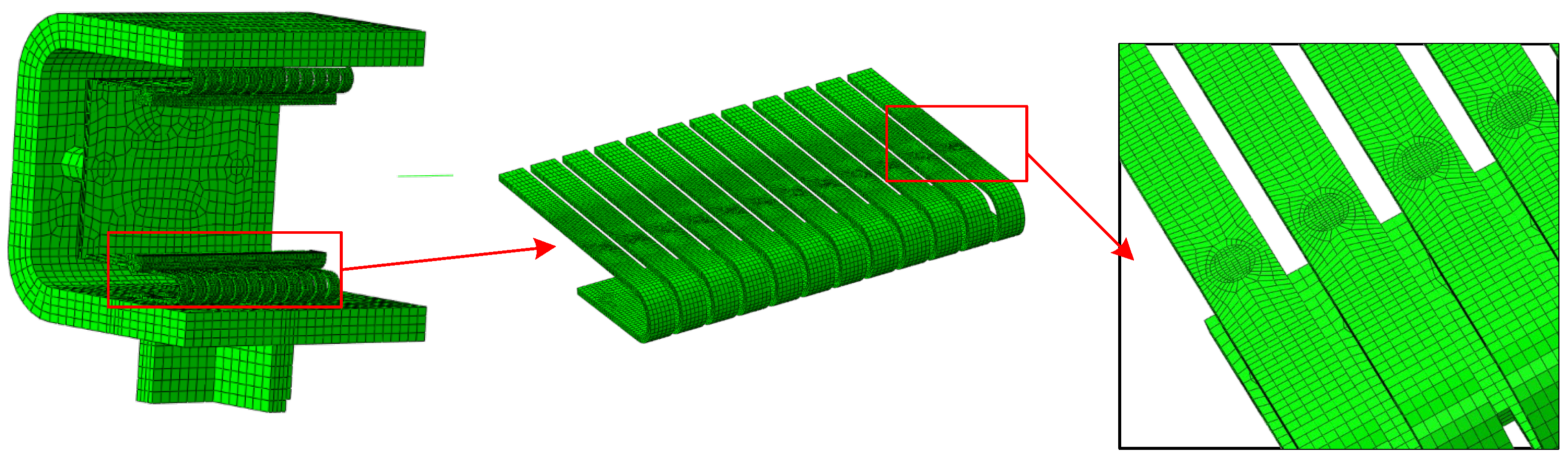
Based on the structural characteristics of the three-phase five-column disconnector, a finite element model was developed, as shown in Figure 5. Only the deformation of the moving contact, fixed contact, and conducting rod was considered. The small deformations of the post insulators and metal supports beneath the fixed contact were neglected, and these components were treated as rigid bodies. In addition, the conducting rod connecting the moving contacts of phases A and B was simplified as a one-dimensional element. The springs behind the fixed contact were modeled using one-dimensional elements, and the corresponding reaction forces were determined from the deformation at the spring locations. Before assembly, the contact fingers of the fixed contact are inclined at 3.2° to the horizontal. During assembly, insertion of the fixing plate forces the contact fingers into a horizontal orientation, indicating that a certain prestress already exists in the contact fingers in the open state. Accordingly, the dynamic simulation of stress and deformation was performed in four steps: The prestress induced by insertion of the fixing plate was first calculated; based on this result, the stress and displacement after closure of the moving contact were calculated (Case N); The moving and fixed contacts were displaced downward together by 10 mm to represent the effect of foundation settlement (Case D); With the settlement held constant, the fixed contact was displaced 50 mm toward the northeast (Case D-NE), northwest (Case D-NW) and southeast (Case D-SE).
Figure 5.
Finite element mesh.
3.2. Contact-Pressure Distributions and Load Redistribution of Contact Fingers
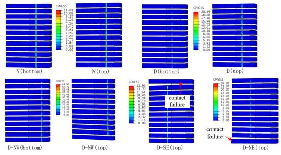
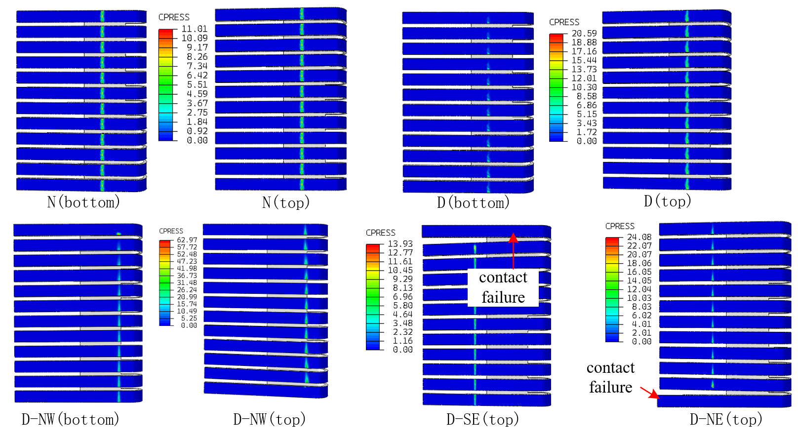
Figure 6 shows the contact pressure of the contact fingers under five operating conditions. It can be clearly observed that both foundation settlement and horizontal displacement cause the contact pressure of the top fingers to increase while that of the bottom fingers decreases. When the fixed contact is displaced eastward, all bottom fingers lose contact and are therefore not shown in Figure 6. The contour plots of the contact pressure distribution show that, without horizontal displacement, the contact pressure is distributed relatively uniformly on both sides of each contact finger, and the contact region is rectangular. In contrast, horizontal displacement causes the contact region to become tapered. This occurs because the constraint imposed by other rigid components causes considerable displacement of the fixed contact, so that only one side of each contact finger remains in effective contact. The decrease in contact pressure and the contraction of the contact area further increase the contact resistance.
Figure 6.
Contact-pressure distributions under different conditions (unit: MPa).
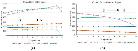
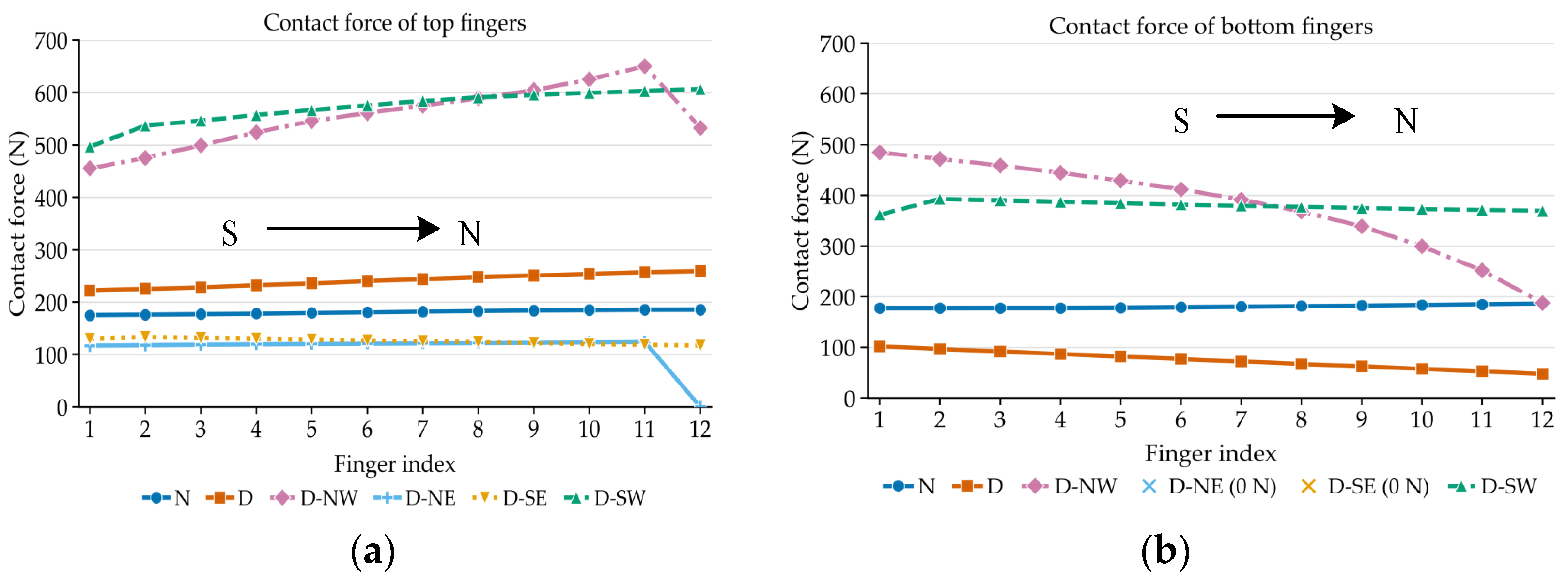
Based on the normal contact stress distribution between the individual contact fingers and the moving contact, the total normal contact force of each finger can be obtained by area integration, as shown in Figure 7. Under normal conditions, the contact forces of all fingers are essentially uniform, at approximately 178 N. When settlement occurs, the contact forces of the top fingers increase overall, whereas those of the bottom fingers decrease overall. Owing to the constraining effect of the conductor connecting rods, the fixed contact tilts under settlement, resulting in higher contact forces for the fingers on the north side of the top contact and on the south side of the bottom contact. When the fixed contact is subsequently displaced in different directions, the contact forces exhibit different variation patterns. Displacement toward the west, i.e., either NW or SW, increases the contact forces of both the top and bottom fingers, thereby improving electrical contact. In contrast, displacement toward the east, i.e., either NE or SE, significantly reduces the contact forces of the top fingers and causes the bottom fingers to lose contact entirely.
Figure 7.
Contact force of the contact fingers under different settlement and displacement conditions. (a) Top fingers. (b) Bottom fingers (contact force for D-NE and D-SE are zero).
4. Electrothermal Failure Mechanism of Multiple Contact Fingers
4.1. Current Redistribution and Heating After Local Loss of Contact
The actual conductive area of a metal contact is composed of surface micro-contact spots. When the normal load decreases, the real contact area decreases, and the influence of constriction resistance and surface film on interfacial resistance increases. Surface oxidation, contamination, and silver coating degradation of field-served contacts further increase interfacial resistance. Figure 7 shows that settlement causes some contact fingers to increase load and others to unload. Figure 6 further shows that after superimposing horizontal displacement, local contact fingers can develop into loss of contact. Thus, under foundation displacement, the multi-contact finger structure first exhibits differentiation of contact states among branches, rather than a synchronous increase in resistance of all branches.
The 24 contact fingers form parallel conductive paths electrically. If the equivalent contact resistance of the i-th contact finger is Ri, the equivalent resistance of the contact finger part Req can be expressed as:
The current distribution relationship for the i-th contact finger Ii is:
After horizontal displacement, if some contact fingers unload and their Ri increases, while other contact fingers decrease their Ri due to increased insertion depth, the two types of changes will superimpose on the total conductance. The first decrease and then increase shown in Figure 4b can therefore be understood from the perspective of parallel branch redistribution: under the 50 mm displacement condition, the contribution of some low-resistance branches to the total conductance may temporarily increase. After the displacement continues to increase, as the contact state changes again, the total resistance rises somewhat.
When some contact fingers lose contact, the current originally shared by 24 contact fingers will be redistributed to the remaining branches. For any branch, its Joule loss Pi is:
Local unloading may both increase Ri and increase the Ii of other branches because the number of effective branches decreases. Therefore, mechanical contact deterioration changes the local thermal load simultaneously through two paths: “resistance increase” and “current redistribution”. For a given total current, even if the total circuit resistance does not change much, the more unevenly the current is distributed among the contact fingers, the more likely the heating of local high-current branches is to increase.
To further illustrate the thermal response that may be caused by contact degradation, a finite element electrothermal model of the contact was established in this paper, and the influence of contact state deterioration on contact temperature rise was analyzed by changing the equivalent contact resistance. Therefore, it is necessary to determine the contact resistance of the contact fingers under different conditions.
4.2. Calculation of Contact Resistance
A bulk-resistance simulation of the disconnector contact circuit gives an overall loop bulk resistance of 9.83 μΩ. The measured circuit resistance of a contact removed after long-term service is 93.4 μΩ; subtracting the bulk resistance, the total contact resistance under the measurement conditions is 93.4 − 9.83 = 83.57 μΩ. The measured total contact resistance includes not only the resistance between the moving and fixed contacts but also that between the measuring clamps and the metal fittings. Since the latter cannot be separated from the available data, all contact resistance is attributed to the contact fingers in this study as a simplification. The upper and lower contact-finger assemblies, each containing 12 fingers, are connected in parallel, so the contact system is modeled as 24 parallel branches.
The contact area of a single contact finger is approximated as a rectangle of length Li and half-width ai. According to the cylinder-on-flat elastic contact model in Ref. [30], its constriction resistance can be obtained as:
where the equivalent elastic moduli of the two contact materials are:
- where E1 and E2 are the elastic moduli of the two contact materials, in Pa, and ν1 and ν2 are the corresponding Poisson’s ratios.
- where Rci is the constriction resistance of the ith contact finger, and ρ is the electricalresistivity of the contact material. The calculations use Li = 12 mm and r = 10 mm.
For the structure considered in this study, the parallel equivalent resistances can be calculated separately for the 12 contact fingers at the top, the 12 contact fingers at the bottom, and all 24 contact fingers. When a contact finger has no contact, it is excluded from the corresponding parallel summation.
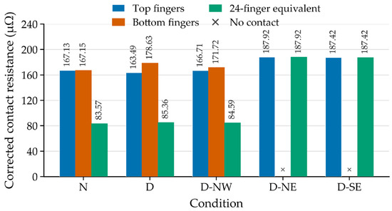
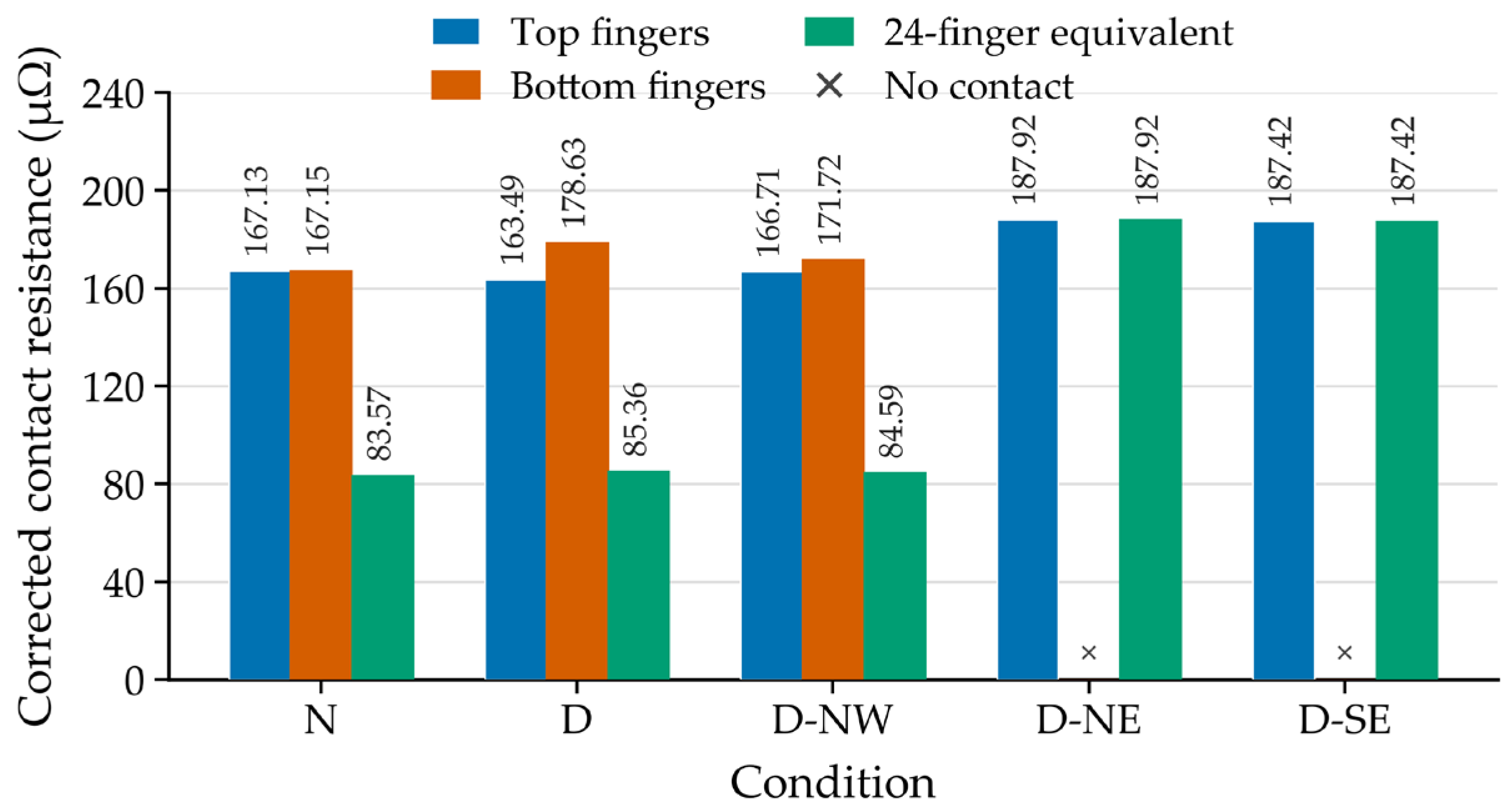
To reduce the systematic deviation between the ideal elastic contact model and the field test results, the field-measured value of 83.57 μΩ under normal operating condition N is taken as the target value, and a correction coefficient is used to calibrate the overall calculation results. The contact resistances of the contact fingers and the resulting parallel equivalent resistance under different operating conditions can then be calculated, as shown in Figure 8.
Figure 8.
Contact resistance of the contact fingers under different settlement and displacement conditions.
4.3. Coupled Electro-Thermal Field Simulation Considering Contact Resistance
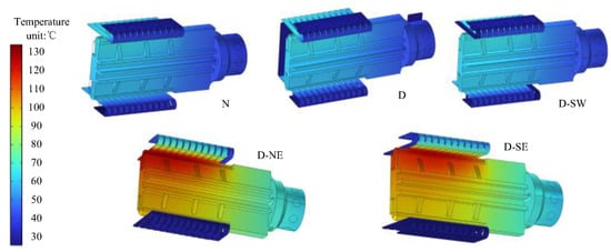
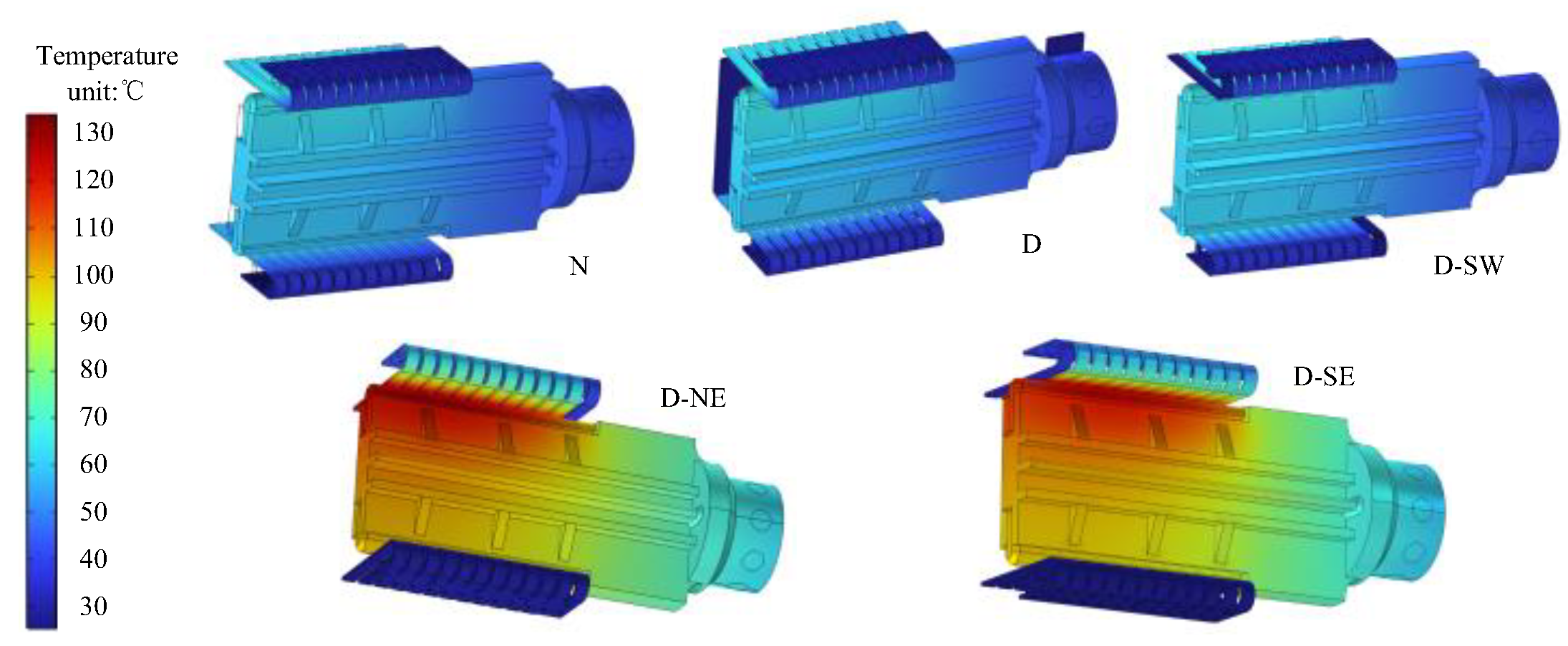
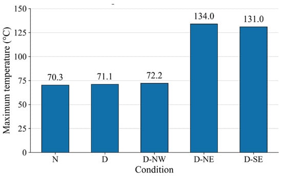
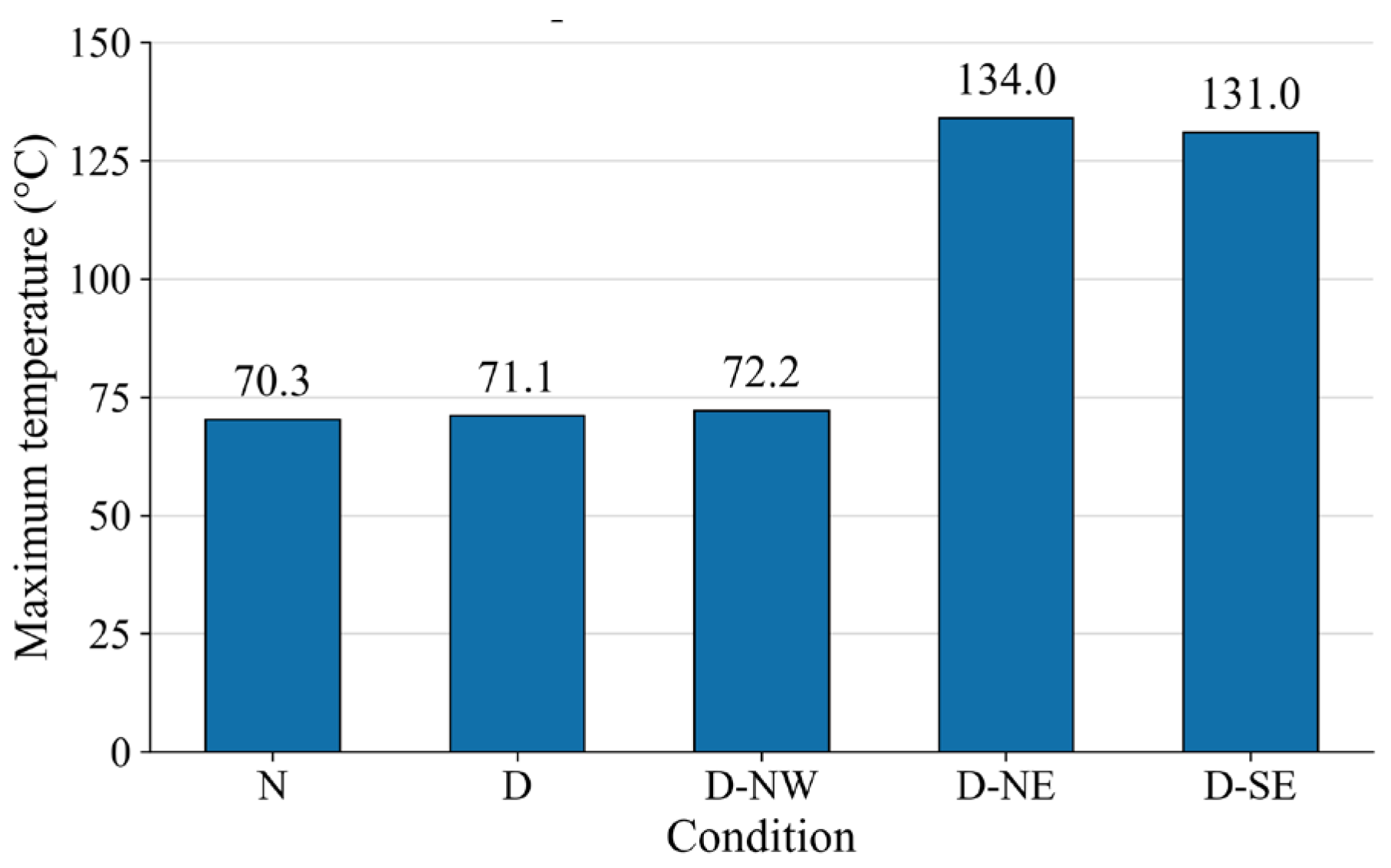
An electro-thermal coupled model was established to analyze the effect of contact resistance variation on the contact temperature rise. The analysis considered the moving and fixed contacts of the A-phase disconnector, the upper part of the post insulator, and a 1 m long connecting rod attached to the moving contact. The other components were sufficiently far from the A-phase contacts and therefore had little effect on the contact temperature. A contact current of 1800 A, an ambient temperature of 20 °C, and a natural convection heat transfer coefficient of 6 W/(m2·K) on the external surfaces were adopted. Since both the contact fingers and conductors were darkened and oxidized, an emissivity of 0.7 was used. The calculated contact resistance of each contact finger under different operating conditions was applied to the corresponding contact region. For fingers that had lost contact, an electrically insulating condition was defined at the interface to prevent current flow. The contact temperatures under different conditions are shown in Figure 9, and the maximum temperatures are in Figure 10.
Figure 9.
Temperature distribution under different contact resistances.
Figure 10.
Maximum temperature of the contacts under different contact resistances.
It can be seen that under the N and D conditions, the maximum temperature rise of the contacts is almost identical. Even under the D-NW condition, the contact temperature increases by only 2 °C. In contrast, under the D-NE and D-SE conditions, the maximum temperature exceeds 130 °C. Combining the contact pressure results in Figure 7 and the contact resistance results in Figure 8, the following conclusions can be drawn:
- (i)
- When the contacts are tilted or their contact condition becomes abnormal owing to external environmental factors, as long as most contact fingers remain in contact, the loop resistance changes little, and the maximum contact temperature remains almost unchanged.
- (ii)
- When the displacement is sufficiently severe that contact degradation occurs across the entire bottom row of contact fingers, the contact temperature increases substantially.
- (iii)
- Considering that outdoor contact fingers may suffer from severe surface contamination, which further deteriorates the contact condition, the remaining current-carrying contact fingers will face more severe operating conditions, and the actual temperature rise may therefore be greater.
4.4. Formation Process of Contact Electrothermal Failure
Combining field damage, circuit resistance tests, and contact pressure calculations, a relatively complete explanation of the development process of this fault can be given. Foundation settlement first changes the relative height of the moving and fixed contacts, causing differences in the insertion depth of the upper and lower contact fingers. When horizontal displacement continues to occur on this basis, the low-load area is further unloaded, and local contact fingers gradually lose contact. In the early stage of failure, other contact fingers can still share the current and may even reduce their own contact resistance due to increased compression, so the total circuit resistance may decrease or show non-monotonic changes. As the number of contact fingers losing contact increases, the number of branches that can stably conduct decreases, and the current gradually concentrates in the remaining contact areas, thereby enhancing local heating.
Under continuous current-carrying conditions, temperature rise in turn affects the contact material and contact interface. The resistivity of copper and copper alloys increases with increasing temperature, and higher temperatures also weaken the ability of elastic contact fingers to maintain compression. If repeated micro-separation occurs at the contact interface, short-term arcs may also occur locally. At this point, the uneven mechanical contact caused by foundation displacement gradually transforms into current and heat concentration, eventually developing into contact ablation. The large-area melting damage of the contact, molten metal spatter, and thermal damage to adjacent insulators at the accident site are consistent with the above evolution process.
From the perspective of operating state judgment, the results of this study also show that evaluating a multi-contact finger disconnector solely by a single total circuit resistance measurement is insufficient. When the force on local contact fingers has already changed significantly, the total circuit resistance may still decrease because the contact of other branches improves. Therefore, for outdoor disconnectors with independent post supports, the relative displacement of the foundation and post, contact alignment, and insertion state should be judged in combination with circuit resistance and infrared temperature measurement results. Particular attention should be paid to the local contact state of long-term service contacts under geometric deviations.
Limited by the existing test conditions, this paper has not yet obtained synchronous data on the clamping force, contact resistance, and branch current of individual contact fingers. Therefore, the amount of current transfer between branches cannot yet be directly given. The existing results can already determine that foundation displacement causes load redistribution and leads to local loss of contact. However, the quantitative correspondence among contact finger pressure, resistance, and temperature rise still needs to be further improved through single-contact calibration tests. The strong wind at the time of the accident may have caused additional displacement. Due to the lack of synchronous displacement records and dynamic data, it was not treated as a deterministic cause of this fault.
5. Conclusions
The post insulator recovered from the accident site was subjected to dimensional measurement, ultrasonic inspection, torsion and bending tests, and bulk density and open-porosity measurements; no pre-existing defect that could have initiated the fracture was identified. The ablation on the fracture surface, the molten-metal spatter, and the composition of the molten material indicate that the severe thermal event in the contact region preceded the final fracture of the post insulator. Considered together with the field damage morphology, the fracture of the post insulator is therefore interpreted as secondary damage following severe contact ablation.
The contacts in different service states exhibited markedly different resistance responses to foundation displacement. For the new contacts in group U, the circuit resistance remained within 81–83 μΩ under the normal position, 10 mm foundation settlement, and combined settlement and 50–80 mm horizontal displacement. In contrast, group S contacts were considerably more sensitive to both settlement and horizontal displacement. At a fixed horizontal displacement of 50 mm toward the northeast, the circuit resistance increased from 82.22 to 145.7 and then to 199 μΩ as the settlement increased from 0 to 10 and 20 mm, respectively. At a fixed settlement of 10 mm and increasing horizontal displacement toward the southeast, the circuit resistance first decreased from 145.6 to 38.16 μΩ as the displacement increased to 50 mm, and then increased to 51.03 μΩ at 80 mm, showing a non-monotonic variation. This difference is consistent with the blackened, oxidized, and contaminated surface and the substantially degraded original silver coating of the field-served contacts.
The contact-mechanical analysis shows that foundation settlement does not unload all contact fingers simultaneously but first redistributes the normal load among them. When horizontal displacement is superimposed, the contact region gradually shifts toward one side of the fingers; some fingers approach zero contact pressure and eventually lose contact, and eastward displacement can cause the entire bottom row to exit contact. Uneven load distribution and contraction of the effective contact region are therefore the main mechanical manifestations of contact degradation. Because the fingers form parallel conductive paths, a local increase in contact resistance can be partly compensated by other branches. Consequently, the total circuit resistance may decrease or vary non-monotonically even when local contact degradation has already occurred, and it alone cannot identify the most unfavorable local contact state.
Electrothermal simulations further show that the maximum contact temperatures under the normal condition (N) and the 10 mm settlement condition (D) are 70.3 and 71.1 °C, respectively, while the settlement combined with northwest displacement condition (D-NW) reaches 72.2 °C. Once the displacement becomes sufficiently severe that most or all of the bottom contact fingers lose contact, the maximum temperature increases to 134 °C under D-NE and 131 °C under D-SE. These results indicate that the number and distribution of effective contact branches control local current concentration and Joule heating, which cannot be inferred from the total circuit resistance alone. Foundation displacement therefore degrades the contact through load redistribution, local loss of contact, and current redistribution; the resulting contact heating can initiate contact ablation and lead to secondary fracture of the post insulator.
For engineering condition assessment, foundation settlement, post inclination, contact alignment, circuit resistance, and infrared temperature should be evaluated together, because a normal or even reduced total circuit resistance does not exclude severe local degradation in long-serving contacts.
Author Contributions
Conceptualization, J.Z. and M.W.; methodology, J.Z.; software, B.C., K.L. and H.W.; validation, J.Z. and B.C.; formal analysis, J.Z. and B.C.; investigation, H.W. and L.W.; resources, J.Z.; data curation, J.Z.; writing—original draft preparation, J.Z.; writing—review and editing, J.Z., T.W. and M.W.; visualization, H.W.; supervision, M.W.; project administration, J.Z. All authors have read and agreed to the published version of the manuscript.
Funding
The authors declare that this study received funding from the Science and Technology Project of State Grid Gansu Electric Power Company (Grant No. 522722260001). The funder had the following involvement with the study: the funder participated in the study design, data collection, analysis, interpretation of data, and the writing of the manuscript.
Data Availability Statement
Data are available on request due to restrictions, e.g., privacy or ethical restrictions. The data presented in this study are available on request from the corresponding author. The data are not publicly available due to the manufacturer’s trade secret.
Conflicts of Interest
Authors Jia Zhang, Bodong Chen, Kang Liu, Hailong Wang, and Luyao Wang were employed by State Grid Gansu Electric Power Research Institute. Author Tiancun Wu was employed by the State Grid Gansu Electric Power Company. The remaining author declares that the research was conducted in the absence of any commercial or financial relationships that could be construed as a potential conflict of interest.
References
- Zhang, L.; Li, R.; Lu, Y.; Rao, X. Inversion method for contact temperature of GIS disconnect switch. IEEE Access 2024, 12, 44553–44563. [Google Scholar] [CrossRef] [Scilit]
- He, S.; Zhao, J.; Qin, C.; Cui, G.; Han, B. Study on thermal-fluid coupling simulation of GIS disconnect switch considering external environmental factors. Energies 2026, 19, 2758. [Google Scholar] [CrossRef] [Scilit]
- Yue, L.; Yang, H.; Yao, C.; Yuan, Y.; Song, K. A non-intrusive thermal fault inversion method for GIS using a POD-Kriging surrogate model and the Grey Wolf Optimizer. Energies 2026, 19, 1962. [Google Scholar] [CrossRef] [Scilit]
- Łapczyński, S.; Szulborski, M.; Szulborski, P.; Kolimas, Ł.; Lange, A. Thermal analysis of a double-break contact based on FEM simulations and experimental studies. Energies 2025, 18, 2748. [Google Scholar] [CrossRef] [Scilit]
- Cao, H.; Luo, L.; Sheng, G.; Jiang, X. Radial identification of the temperature rise rate of GIS busbar conductors based on temperature gradients. IEEE Trans. Power Deliv. 2024, 39, 3514–3524. [Google Scholar] [CrossRef] [Scilit]
- Cao, H.; Chen, X.; Li, F.; Luo, L.; Sheng, G.; Jiang, X. Method for sensing the temperature rise rate of GIS busbar conductors considering transient ambient temperature. IET Sci. Meas. Technol. 2025, 19, e70030. [Google Scholar] [CrossRef] [Scilit]
- Szulborski, M.; Łapczyński, S.; Kolimas, Ł.; Kozarek, Ł.; Cichecki, H.; Sul, P.; Owsiński, M.; Berowski, P.; Baczyński, D.; Wesołowski, M. Examination of electrodynamic forces in high voltage disconnector related to the short-circuit current using the digital twin technology. IEEE Access 2024, 12, 75701–75717. [Google Scholar] [CrossRef] [Scilit]
- Yan, P.; Chang, C.; Hua, D.; Huang, H.; Liu, S.; Cui, P. Adaptive disconnector states diagnosis method based on adjusted relative position matrix and convolutional neural networks. Sensors 2025, 25, 1701. [Google Scholar] [CrossRef] [Scilit]
- Zhang, C.; Ma, H.; Sun, W. Mechanical fault diagnosis method of a disconnector based on improved Dung Beetle Optimizer-multivariate variational mode decomposition and convolutional neural network-bidirectional long short-term memory. Machines 2025, 13, 332. [Google Scholar] [CrossRef] [Scilit]
- Andras, A.; Popescu, F.D.; Radu, S.M.; Pasculescu, D.; Brinas, I.; Radu, M.A.; Peagu, D. Numerical simulation and modeling of mechano-electro-thermal behavior of electrical contact using COMSOL Multiphysics. Appl. Sci. 2024, 14, 4026. [Google Scholar] [CrossRef] [Scilit]
- Beloufa, A. The effect of an auxiliary spring on the decrease of contact resistance and contact temperature for power automotive connector. Proc. Inst. Mech. Eng. Part D. J. Automob. Eng. 2025, 239, 3920–3932. [Google Scholar] [CrossRef] [Scilit]
- Li, Y.H.; Shen, F.; Güler, M.A.; Ke, L.-L. Modeling multi-physics electrical contact on rough surfaces considering elastic-plastic deformation. Int. J. Mech. Sci. 2024, 269, 109066. [Google Scholar] [CrossRef] [Scilit]
- Li, Y.H.; Shen, F.; Güler, M.A.; Ke, L.-L. An efficient method for electro-thermo-mechanical coupling effect in electrical contact on rough surfaces. Int. J. Heat Mass Transf. 2024, 226, 125492. [Google Scholar] [CrossRef] [Scilit]
- Wang, W.; Sui, Y.; Ge, X.; Zhang, H. An efficient method for solving electrical constriction resistance of rough surfaces. Tribol. Int. 2024, 197, 109808. [Google Scholar] [CrossRef] [Scilit]
- Li, Y.H.; Ke, L.L.; Zhou, K.; Chang, G.-G.; Güler, M.A.; Shen, W.-W.; Shen, F. On the multi-physics elastoplastic electrical contact of rough surfaces. Tribol. Int. 2025, 204, 110418. [Google Scholar] [CrossRef] [Scilit]
- Li, Y.H.; Ke, L.L.; Chang, G.G.; Güler, M.A.; Shen, F. On the electrical contact resistance model of rough surfaces based on multi-physics modeling. Int. J. Solids Struct. 2025, 321, 113583. [Google Scholar] [CrossRef] [Scilit]
- Wang, C.; Wang, X.; Guo, C. Research on the estimation model of electrical parameters of silver-based contacts based on surface morphology. Sensors 2025, 25, 312. [Google Scholar] [CrossRef] [Scilit]
- Goeury, L.; Fouvry, S.; Guillonneau, G.; Graton, O.; Endre, P. Influence of a copper interlayer on the electrical contact resistance of a nickel-silver-plated interface subjected to fretting wear. Wear 2025, 570, 205886. [Google Scholar] [CrossRef] [Scilit]
- Song, J.; Tuelling, S.; Hengstler, J. Correlation between wear and fatigue properties and the lifetime of silver coated electrical connectors. Wear 2025, 570, 205971. [Google Scholar] [CrossRef] [Scilit]
- Wang, D.; Xu, J.; Wang, F.; Zhao, Y.; Xiang, Z.; Ding, H. A comprehensive review on the fretting wear of electrical contact interface. Friction 2025, 13, 9441012. [Google Scholar] [CrossRef] [Scilit]
- He, W.; Feng, Y.; Wu, S.; Wu, K.; Ye, J.; Wang, W. Numerical simulation on the effect of current intensity on electrical contact performance of electrical connectors subject to micro-slip wear. Wear 2024, 542–543, 205270. [Google Scholar] [CrossRef] [Scilit]
- Liu, X.L.; Hu, S.X.; Xiao, Q.; Deng, G.-H.; Zheng, Y.-T.; Gao, M.-S.; Zhang, D.; Cao, H.-Y.; Wang, Z.; Chen, D.-Y.; et al. An investigation of the electrical contact failure of JPT electric connectors used in automobiles under multiple stresses. Wear 2024, 552–553, 205458. [Google Scholar] [CrossRef] [Scilit]
- Wu, D.Y.; Zhai, G.F.; Zhou, X.; Xu, L.; Zhang, M.-X. Effect of coating plasticity parameters on the fretting wear behavior of electrical contacts. Tribol. Int. 2025, 210, 110760. [Google Scholar] [CrossRef] [Scilit]
- Doutriaux, T.; Fouvry, S.; Larousse, S.; Isard, M.; Graton, O.; Bouchet, M.I.d.B. How transfer film formation in bronze/silver-graphite sliding contact drives its electrical performance. Wear 2025, 570, 205976. [Google Scholar] [CrossRef] [Scilit]
- Xu, Y.; Wu, Y.; Jackson, R.L. Electrical contact with dielectric breakdown of interfacial gap. J. Tribol. 2025, 147, 051109. [Google Scholar] [CrossRef] [Scilit]
- Standard&’s Q/GDW 407-2010; Guide for On-Site Inspection of High-Voltage Porcelain Post Insulators. China Electric Power Press: Beijing, China, 2010.
- Standard&’s GB/T 8287.1-2008; Indoor and Outdoor Post Insulators for Systems with Nominal Voltage Greater than 1000 V - Part 1: Test on Insulators of Ceramic Material or Glass. Standards Press of China: Beijing, China, 2008.
- Standard&’s GB/T 8411.2-2008; Ceramic and Glass Insulating Materials - Part 2: Methods of Test. Standards Press of China: Beijing, China, 2008.
- Standard&’s GB/T 772-2005; Technical Specifications of Porcelain Element for High Voltage Insulators. Standards Press of China: Beijing, China, 2005.
- Ren, W.; Zhang, C.; Sun, X. Electrical Contact Resistance of Contact Bodies with Cambered Surface. IEEE Access 2020, 8, 93857–93867. [Google Scholar] [CrossRef] [Scilit]
Disclaimer/Publisher’s Note: The statements, opinions and data contained in all publications are solely those of the individual author(s) and contributor(s) and not of MDPI and/or the editor(s). MDPI and/or the editor(s) disclaim responsibility for any injury to people or property resulting from any ideas, methods, instructions or products referred to in the content. |
© 2026 by the authors. Licensee MDPI, Basel, Switzerland. This article is an open access article distributed under the terms and conditions of the Creative Commons Attribution (CC BY) license.