


Abstract
The growing use of nonlinear loads in industrial and residential applications degrades power quality through harmonic distortion and increased reactive power demand. Shunt active power filters (SAPFs) mitigate these disturbances at the point of common coupling (PCC). This paper proposes a modified packed E-cell nine-level inverter (MPEC9) for a single-phase SAPF. A Synergetic Model Predictive Decoupled Powers Control (DPC-SMPC) strategy combines synergetic control theory with model predictive control to regulate grid-side active and reactive powers while maintaining balanced DC-bus capacitor voltages. In this algorithm, the defined macro-variable is predicted to determine the optimal voltage vector associated with the active and reactive power references in a single evaluation. Subsequently, the capacitor voltages are predicted for all admissible switching states and incorporated into the cost function alongside the optimal voltage vector. The proposed DPC-SMPC achieves the control objectives with reduced computational burden. The proposed inverter and control strategy are evaluated through processor-in-the-loop (PIL) co-simulation. Comparative results against the DPC-MPC strategy demonstrate improved performance across the evaluated criteria and lower computational requirements, supporting the effectiveness of the proposed approach for power quality improvement and coordinated power regulation in the investigated single-phase SAPF system under evaluation.
1. Introduction
High-quality electrical power is increasingly demanded and has become increasingly important in several industrial and residential applications. Nevertheless, the increasing integration of power electronic converters and variable-speed drives, which are inherently nonlinear loads, has significantly degraded the quality of electrical power [1,2,3,4]. This degradation is mainly manifested in the form of harmonic distortion, voltage fluctuations, and reactive power imbalance, which can adversely affect the performance, reliability, and efficiency of power systems. Power quality disturbances negatively affect equipment performance, increase energy losses, and compromise the efficiency and reliability of electrical power systems. To overcome this issue, shunt active power filters (SAPFs) based on voltage-source inverters (VSIs) have attracted much attention as an effective solution to improve power quality and supply clean and stable electrical power to sensitive loads. In contrast to conventional passive filters, which can only compensate certain harmonic frequencies, SAPFs with advanced control strategies can provide dynamic and real-time compensation for a wide range of power quality issues [1,2,3,4].
Multilevel inverter (MLI) topologies have attracted considerable interest in SAPF applications because of their potential to improve power quality. However, increasing the number of output voltage levels in conventional configurations generally requires additional power electronic components, leading to higher converter costs [2,3,4,5,6,7,8]. This trade-off has motivated the development of alternative MLI structures that seek to achieve a higher number of voltage levels with fewer devices. These configurations use different arrangements of active switches, isolated DC sources, and auxiliary components to minimize the overall number of components [9]. Consequently, the selection of an appropriate topology involves balancing the desired output voltage levels against the number and arrangement of the required components. Among these alternatives, the Packed U-Cell (PUC) inverter [10] offers a compact configuration that combines flying capacitor (FC) and cascaded H-bridge (CHB) topologies and operates from a single DC source. It can generate a five- or seven-level output voltage using only six switches and one DC capacitor. The multilevel voltage generation and the reduced number of components make the PUC topology an attractive candidate for SAPF applications where compactness and cost of the converter are important design considerations. The PUC inverter topology was modified for use in SAPF systems [11]. The MPUC offers voltage-boosting capability without increasing the number of power electronic components relative to the conventional PUC inverter. However, its output is limited to five voltage levels.
To increase the number of output voltage levels, Sharifzadeh et al. developed a new Packed E-Cell (PEC) topology by replacing the U-cells of the PUC structure with E-cells. This configuration generates a nine-level output voltage using only one four-quadrant switch, six active switches, and two DC capacitors [12]. An alternative nine-level Packed E-Cell inverter for grid-connected PV systems was proposed by Laib et al. [13]. Their PEC9 configuration retains the same number of components as the original PEC9 topology.
On the other hand, several classical control schemes have been presented in the literature for SAPF systems using MLIs [14,15]. Voltage-oriented control (VOC) based on PI regulators and a modulation stage using pulse width modulation (PWM) or space vector modulation (SVM) is widely employed [15]. In this approach, DC-bus capacitor voltage balancing is integrated into the modulation stage, resulting in greater control complexity. Furthermore, PI regulators exhibit several limitations, such as slow dynamic response and significant overshoot or undershoot under critical operating conditions, which deteriorate the SAPF system performance. Therefore, several researchers have employed advanced control strategies to enhance the VOC method, including sliding mode control (SMC) [16], synergetic control (SC) [17], and super-twisting sliding mode control, as robust alternatives for improving power quality. Among SAPF control strategies, DPC has received considerable attention. Early approaches primarily targeted operation with ideal grid voltages [18,19], whereas later developments sought to preserve control performance in the presence of supply-voltage distortion [20,21]. Nevertheless, their ability to handle the combined effects of voltage imbalance and distortion remained inadequate, as did finite-control-set model predictive control (FCS-MPC) [22]. Compared with conventional control schemes, predictive direct power control (PDPC) offers a faster dynamic response, improved transient performance, and direct power regulation [21]. By predicting the system’s power evolution, PDPC enables precise control of and without requiring complex modulation stages [23].
In [24], the authors propose a fractional-order predictive direct power control strategy for a shunt active power filter connected to a hybrid renewable energy system with battery storage. The method uses fractional calculus, predictive control, and space vector modulation to generate the switching pulses. The results indicate that the current harmonic distortion, DC-link voltage ripple, and transient response are improved compared with DPC-PI and FO-DPC-SVM. However, the validation is limited to simulations. In [25], the authors investigated predictive DPC approaches incorporating Gray Wolf Optimization (GWO) and Ant Lion Optimization (ALO) for SAPF control. The two approaches were implemented and experimentally evaluated using the dSPACE 1104 platform, with a conventional control strategy serving as the benchmark. This comparison provided an assessment of their relative effectiveness under the investigated operating conditions. The experimental results showed that the ALO-based predictive DPC achieved better SAPF performance than both the GWO-based approach and the conventional strategy, highlighting its potential for improving the performance of predictive power control.
In [26], a switching-table-based DPC strategy was proposed for a three-phase SAPF. The control scheme combines a PI regulator with an anti-windup mechanism for DC-link voltage regulation and a phase-locked loop (PLL) incorporating a multivariate bandpass filter for grid-voltage synchronization. These elements support the operation of the overall control scheme, while the switching table determines the switching actions. The reported results demonstrated improved SAPF performance compared with the conventional method. Nevertheless, reliance on a predefined switching table remains a potential limitation, as it may restrict the controller’s adaptability and compromise its robustness under varying operating conditions. The authors of [27] developed a sliding mode control scheme for a three-phase shunt active power filter based on a simplified model in the – reference frame. Controller stability was established under the assumption of a constant DC-link voltage, while simulation results showed a reduction in grid current THD from 21.54% to 3.54%. Nevertheless, neglecting DC-link voltage dynamics restricts the scope of the stability analysis. Furthermore, the reported simulation results do not establish the controller’s performance under practical operating conditions.
The authors of [28] proposed a model predictive control strategy for SAPF applications based on constrained optimization, with stability proved by a formal Lyapunov analysis. The simulation and hardware-in-the-loop tests showed good harmonic mitigation under balanced, unbalanced, and distorted supply-voltage conditions, which is better than an IDA-PBC strategy. However, the validation presented does not include a physical SAPF prototype, so performance under real converter nonidealities remains to be established. In [29], the authors proposed an optimal harmonic control strategy for high-power, medium-voltage active power filters operating at low switching frequencies. The method combines Kalman-filter-based harmonic estimation, optimal model predictive control, and selective harmonic control PWM for the regulation of magnitude and phase of multiple low-order harmonics. An artificial neural network is employed to reduce the computation requirements of real-time PWM implementation. Experimental validation with a three-level neutral-point-clamped converter showed better performance than conventional PI control. However, the combination of estimation, optimization, and learning-based techniques adds more architectural complexity. Moreover, the summary does not show the neural network’s ability to generalize beyond the training conditions, or the success of the compensation for the harmonics outside of the selected low-order range.
These strategies overcome the drawbacks associated with PI regulators. Nevertheless, the design of the modulation stage remains complicated due to the additional requirement for DC-bus capacitor voltage balancing. Finite-control-set model predictive control (FCS-MPC) has been widely adopted for power electronic converters, particularly multilevel inverters, because it readily incorporates DC-bus capacitor voltage balancing into the control objectives [22,30,31,32,33,34,35,36]. This approach also offers improved dynamic and steady-state performance compared with conventional control strategies. Despite these advantages, limited steady-state tracking accuracy and a high computational burden remain key limitations.
To overcome these limitations, this paper presents a modified nine-level Packed E-Cell (MPEC9) inverter with a reduced power electronic component count for a single-phase SAPF system. The proposed topology comprises only six bidirectional active switches, one four-quadrant switch, and three capacitors. In addition, synergetic control theory is integrated with model predictive control to develop a novel decoupled active and reactive power control strategy for the proposed SAPF system. The control objectives of DPC-SMPC are to regulate the grid active and reactive powers while balancing the DC-bus capacitor voltages. Processor-in-the-loop (PIL) co-simulation will be conducted to assess the performance of the proposed system. Furthermore, a comparison between the proposed DPC-SMPC and conventional DPC-MPC will be carried out under several critical operating conditions. The main contributions of this paper are outlined below:
- This paper introduces an advanced single-phase MPEC9 inverter for SAPF applications to replace conventional two-level VSIs.
- Synergetic control is combined with DPC-MPC to develop a novel DPC-SMPC.
- The proposed DPC-SMPC achieves a significant reduction in computational burden.
- The control performance of the DPC-SMPC is validated through processor-in-the-loop (PIL) co-simulation using a C2000 F28379D microcontroller LaunchPad from Texas Instruments, Dallas, TX, USA.
The paper is organized into six sections. Following the introduction, Section 2 describes the modeling of the proposed MPEC9 inverter for SAPF applications. Section 3 presents the DPC-MPC scheme used in the MPEC9-based single-phase SAPF system. Building on this framework, Section 4 details the development of the proposed DPC-SMPC strategy. Section 5 reports the processor-in-the-loop (PIL) validation results and discusses the performance of the proposed approach. Finally, Section 6 presents the conclusions.
2. Modeling of MPEC9 Inverter for SAPF Systems
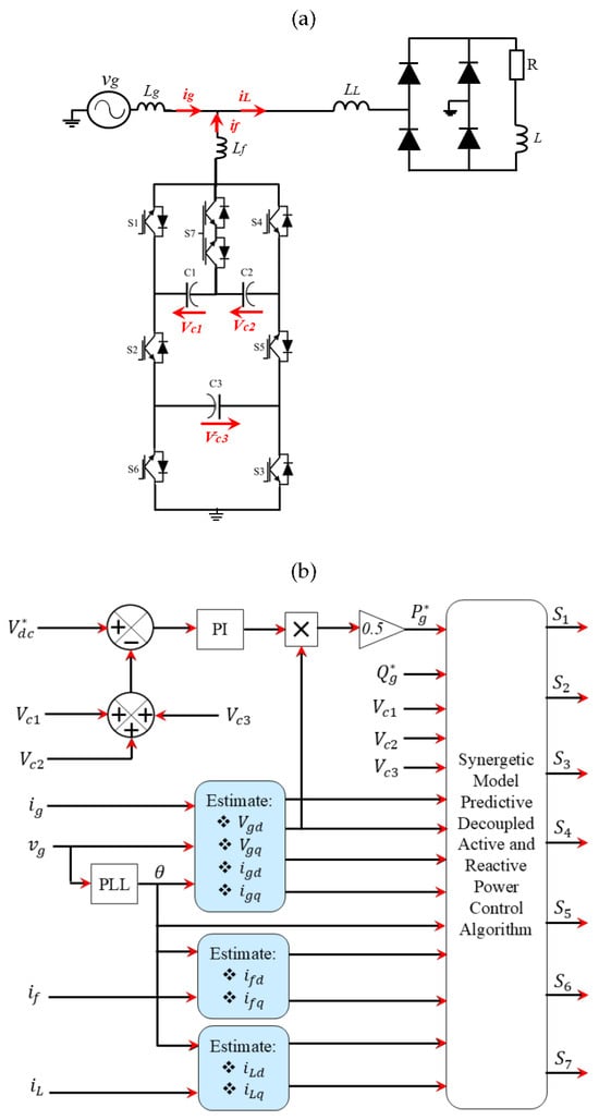
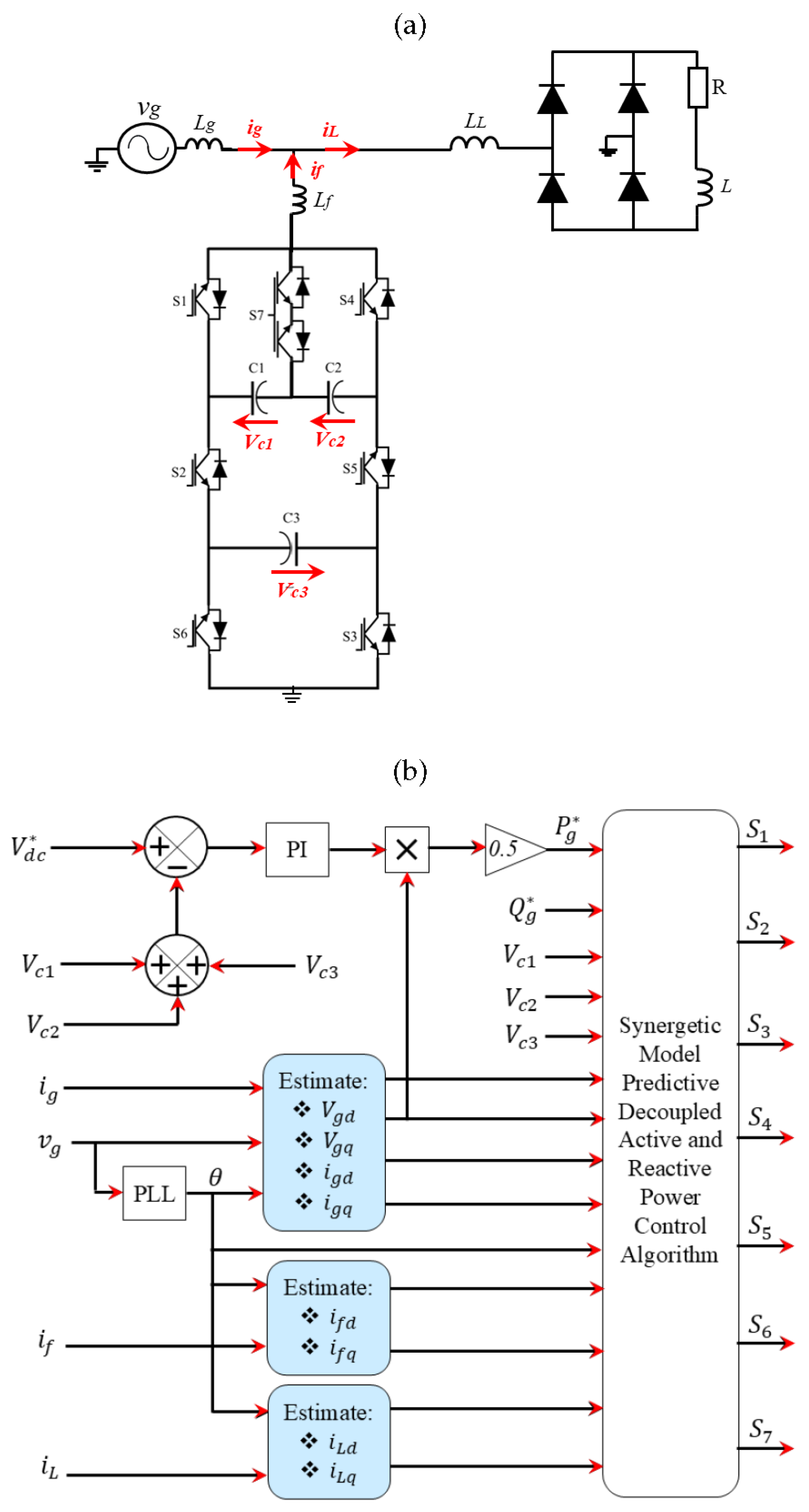
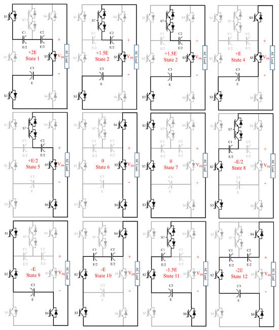
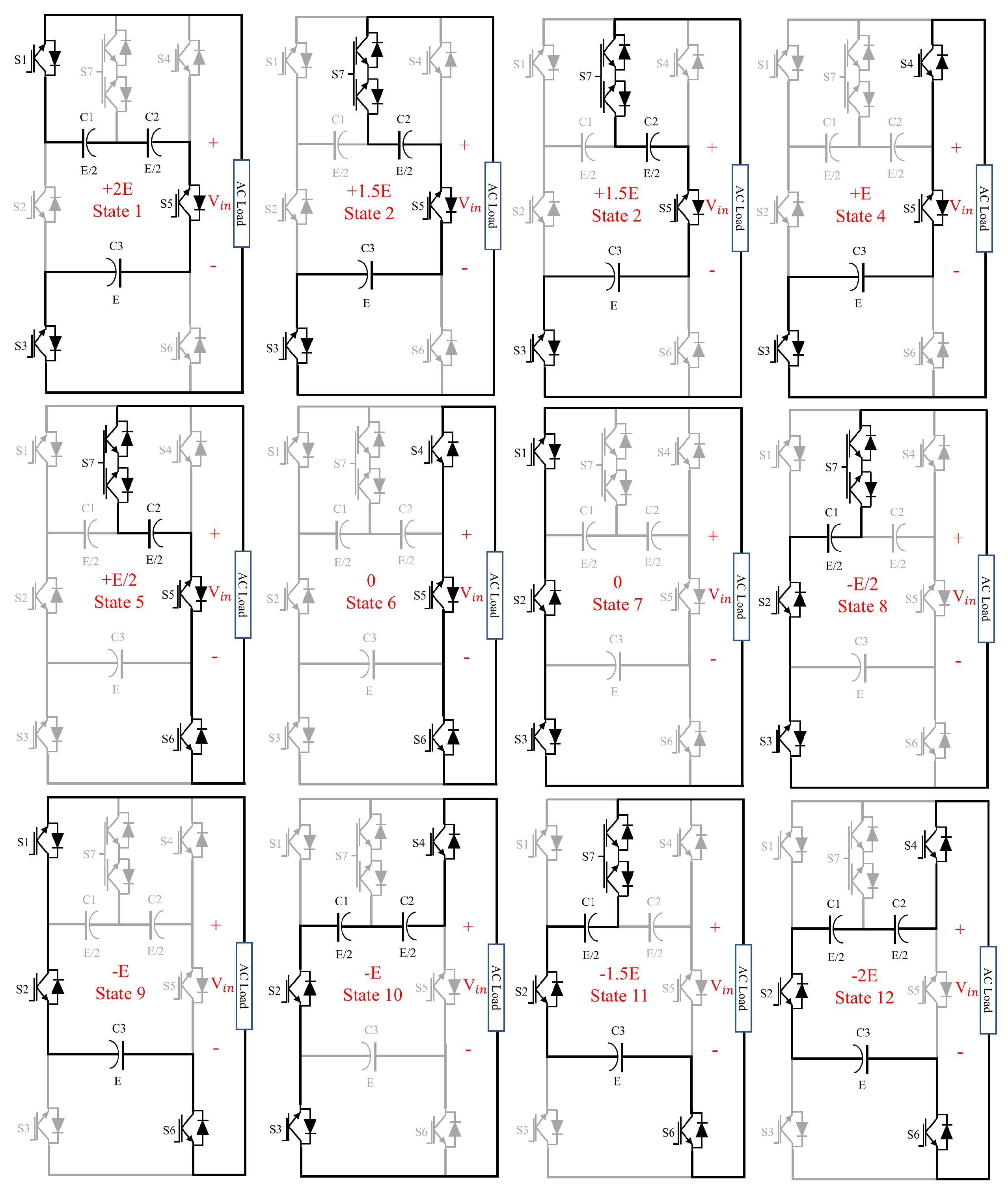
The suggested SAPF structure based on the novel MPEC9 inverter topology is illustrated in Figure 1a. This system is composed of an AC source, a nonlinear load connected in series, and the MPEC9 inverter connected in parallel to the grid via a line inductor () at the point of common coupling (PCC). Reactive power compensation is achieved using the proposed MPEC9 inverter, which injects compensating harmonic currents into the grid to reduce the grid-current harmonics generated by nonlinear loads at the PCC. Six bidirectional active switches, one four-quadrant switch, and three capacitors are the electronic components of the MPEC9 inverter, as presented in Figure 1. All possible MPEC9 switching states are presented in Figure 2 and summarized in Table 1.
Figure 1.
System description: (a) Global system configuration and (b) Global control scheme.
Figure 2.
Switching configurations of the proposed MPEC9 inverter.
Table 1.
Switching states of the MPEC9 inverter topology.
The proposed control scheme based on novel synergetic model predictive decoupled active and reactive power control is presented in Figure 1b. A simple PI regulator is employed to regulate the DC link voltage and estimate the grid active power reference, while the grid reactive power reference is set to zero in order to ensure unit power factor.
Based on Figure 1a, the mathematical model of the SAPF system using the single-phase MPEC9 inverter in the natural frame can be expressed as [22]:
where is the filter current, V the voltage vector generated by the MPEC9 inverter, the grid voltage, and R, L are the filter components.
To control the grid active and reactive powers, the measured filter current, load current, grid current, and grid voltage are expressed in the stationary reference frame. Each measured signal forms the -axis component, while its corresponding -axis component is generated by introducing a phase shift. This representation provides the orthogonal signal components required to formulate the power control scheme [37]. Using this approach, the mathematical model presented in Equation (1) can be transformed into the synchronous d–q reference frame as follows [22]:
where and represent the voltage vector components in the d–q frame, while is the grid angular frequency, which is estimated using the basic single-phase PLL presented in [38].
The voltage is set to the voltage vectors generated by the MPEC9 inverter, while is maintained at zero.
3. Decoupled Power Control Model Predictive for Single Phase SAPF System Using MPEC9
The design of a scheme for the decoupled power control model predictive control (DPC-MPC) of a single-phase SAPF system using the MPEC9 inverter is presented in this section. The DPC-MPC aims to control the active and reactive powers injected into the grid and the voltage balance of the DC-bus capacitor. These objectives are integrated into the following DPC-MPC cost function:
where and denote the future values of the active and reactive power references, respectively, and , , and represent the DC-bus voltages. The weighting factor determines the contribution of the DC-bus capacitor voltage-balancing term, which is estimated using the method presented in [39].
The and can be calculated by the following equations:
where
The DC-bus capacitor voltages are predicted using a model that relates their evolution to the corresponding capacitor currents and the grid current, as follows [13]:
Applying the forward Euler method yields the following discrete-time model of the DC-bus capacitor voltages [13]:
where , , and can be calculated using the switching states of the MPEC9 inverter as:
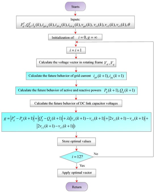
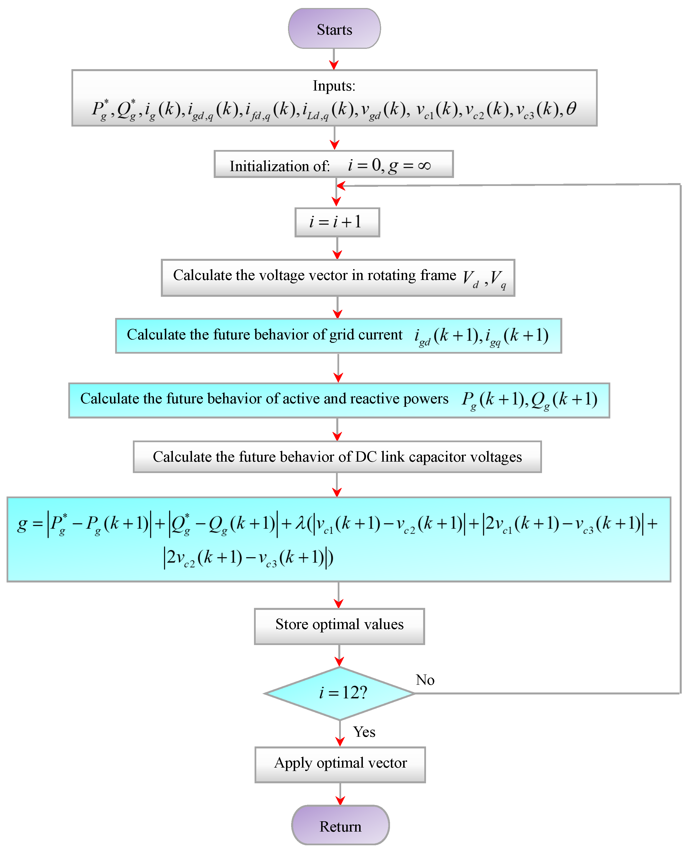
Figure 3 provides an overview of the DPC-MPC strategy implemented in the MPEC9-based single-phase SAPF system. At each sampling instant, the controller acquires the measured grid, filter, and load currents, together with the grid voltage and the voltages across the three DC-bus capacitors. These measurements serve as inputs to the predictive models, which evaluate the system response for every admissible switching state. Specifically, the controller predicts the d–q components of the grid current, the grid active and reactive powers, and the individual DC-bus capacitor voltages. The predicted quantities are used to calculate the cost function for each candidate switching state. The controller compares these values to choose the state that best matches the control goals described by the cost function. Then, the switching state with the least cost is chosen and applied in the next sampling interval. This process of prediction, evaluation, and selection is repeated at each sampling instant, thus allowing the switching decision to be adapted on the basis of the most recent measurements.
Figure 3.
Flowchart of DPC-MPC.
4. Novel Decoupled Power Control Synergetic Model Predictive Control for Single Phase SAPF System Using MPEC9
To improve DPC-MPC performance, we combine synergetic control theory with finite-control-set model predictive control. The following section details the proposed DPC-SMPC scheme. The macro-variable is selected as follows:
The following expression defines the macro-variable derivative:
The synergetic controller employs the following evolution constraint to ensure exponential convergence of the system states to the desired manifold [17]:
The parameter T denotes a positive constant. By inserting Equations (11) and (14) into Equation (12), the following expression is obtained:
where
Equation (13) can be simplified as:
The prediction of Equation (16) for the next sampling period using Euler is expressed as follows:
The and are included in the cost function g instead of the predicted active and reactive power references as follows:
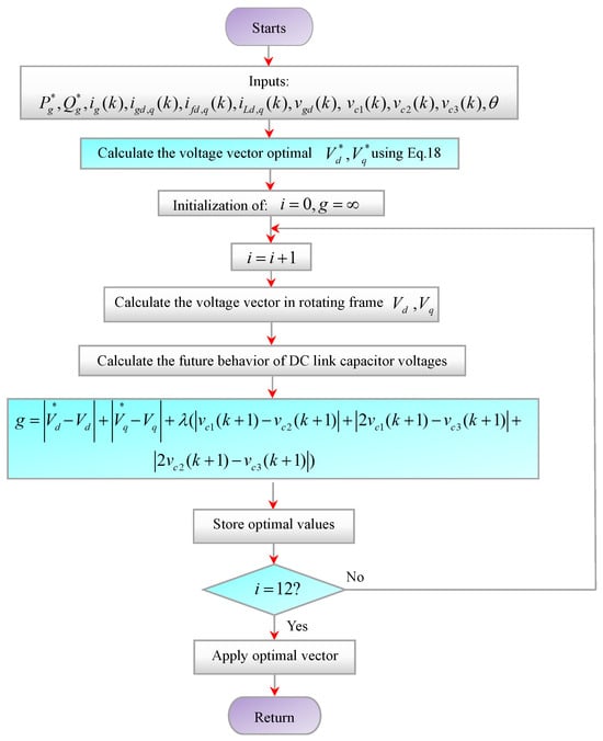
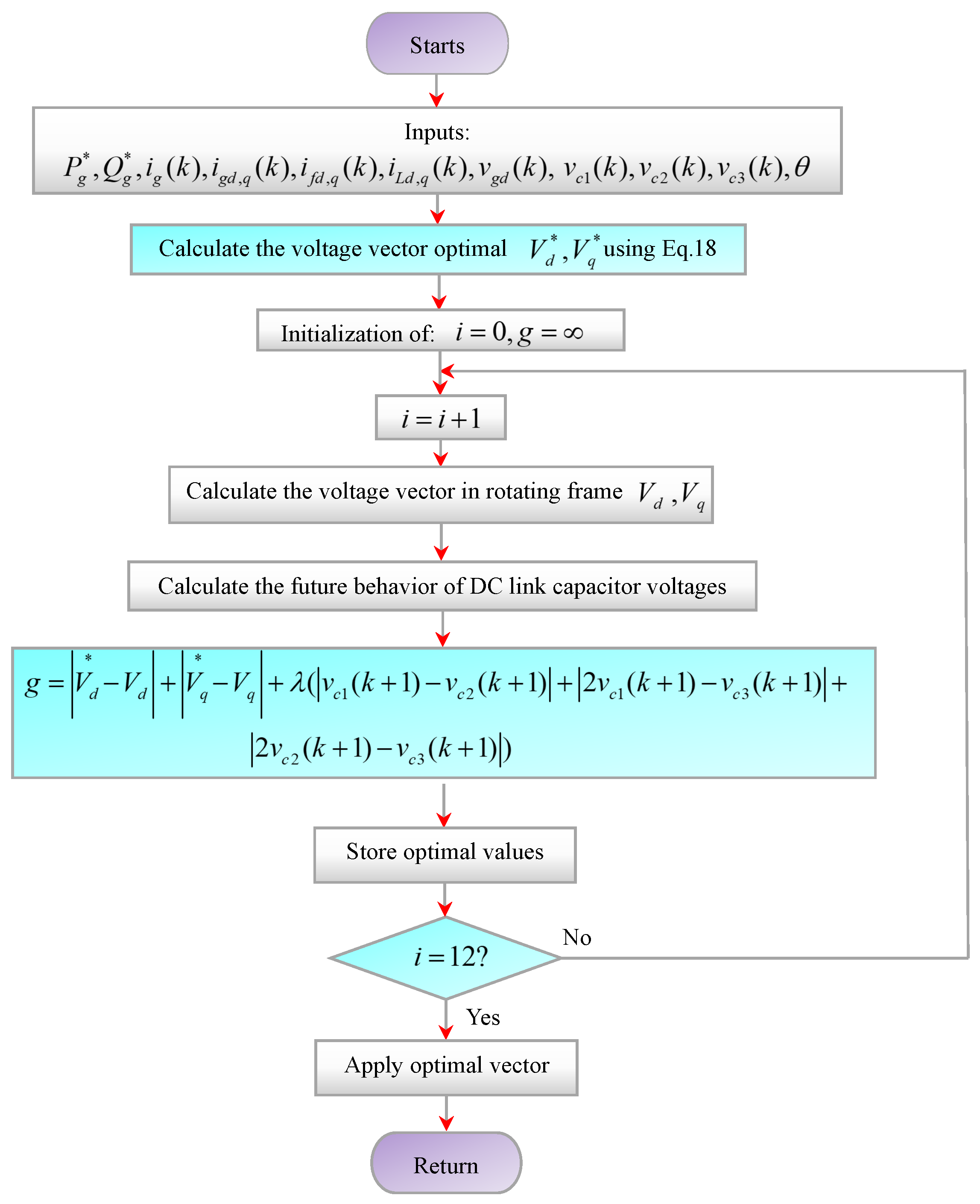
During each sampling interval, the optimal voltage references corresponding to the predicted grid active and reactive powers are calculated in a single step using the measured grid, filter, and load currents, along with the grid voltages. The proposed DPC-SMPC subsequently predicts the DC-bus capacitor voltages and evaluates the cost function for each admissible switching state. The state yielding the minimum cost is selected for application in the following sampling interval. This procedure achieves the control objectives while substantially reducing the computational burden. Figure 4 outlines the operating principle of the proposed DPC-SMPC scheme for the MPEC9-based single-phase SAPF system.
Figure 4.
Flowchart of the DPC-SMPC.
5. Results Analysis
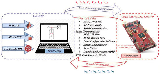
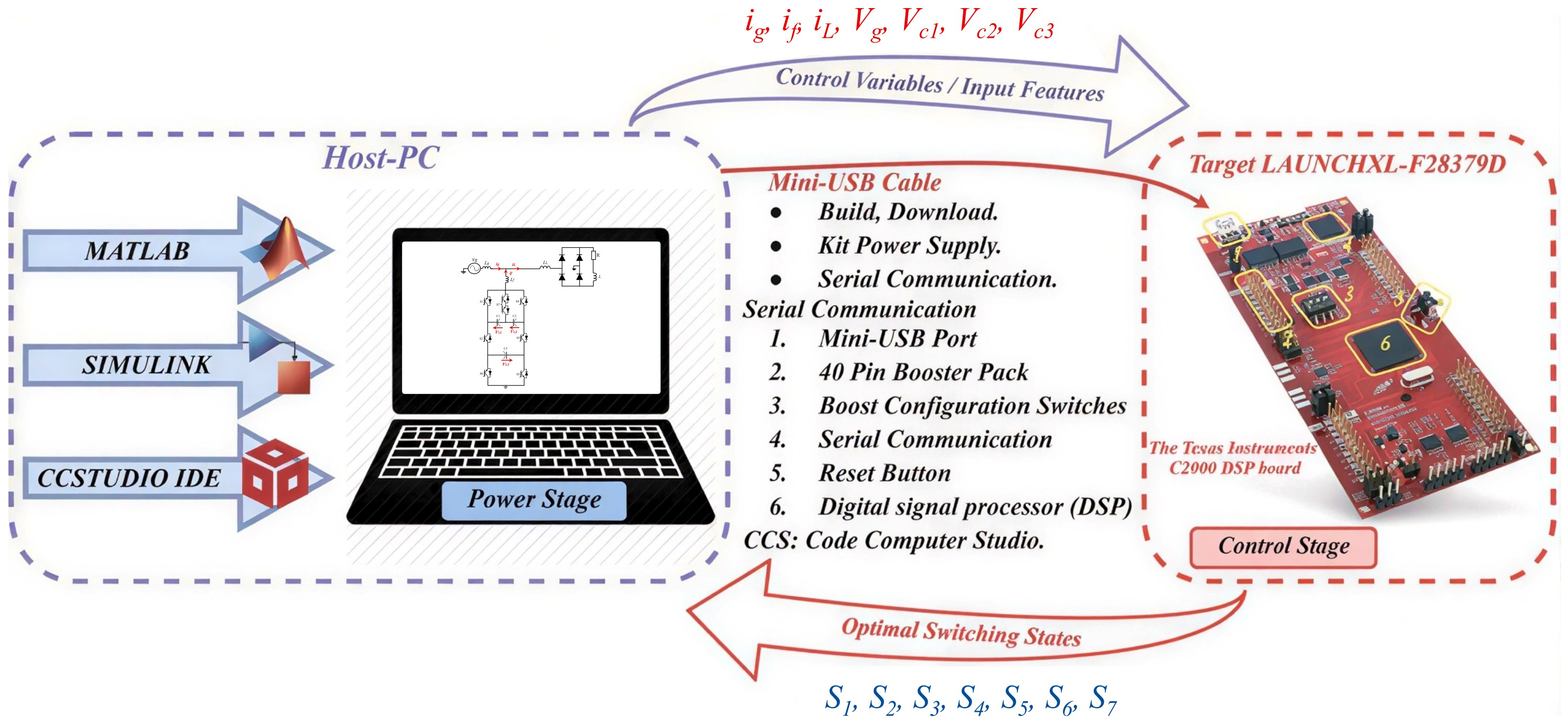
In this section, a PIL prototyping framework is used to evaluate the performance of the DPC-SMPC strategy for the MPEC9-based single-phase SAPF system. The PIL co-simulation setup consists of a host PC and a C2000 LAUNCHXL-F28379D from Texas Instruments, Dallas, TX, USA. development board. The board features a 32-bit microcontroller with 1 MB of flash memory, a clock frequency of 168 MHz, a floating-point unit, dedicated DSP instructions, and 192 KB of SRAM.
In this configuration, the control algorithm runs on the C2000 microcontroller, from Texas Instruments, Dallas, TX, USA. while the MPEC9-based single-phase SAPF is simulated in MATLAB/Simulink (R2024B, MathWorks, Natick, MA, USA). on the host PC. Communication between the host PC and the target board is established through a virtual serial COM port, enabling data exchange during the PIL co-simulation [40].
At each sampling instant, the host PC transmits the measured signals—, , , , , , , and —to the development board. Using these measurements, the DPC-SMPC algorithm evaluates the candidate switching states and determines the optimal one. The selected state is then returned to the host PC and applied to the simulated system during the next sampling interval. This measurement, computation, and feedback cycle is repeated at every sampling period.
Figure 5 illustrates the PIL co-simulation setup, and the results presented in this section are obtained using the system parameters listed in Table 2.
Figure 5.
Diagram of the PIL co-simulation.
Table 2.
Parameters of SAPF.
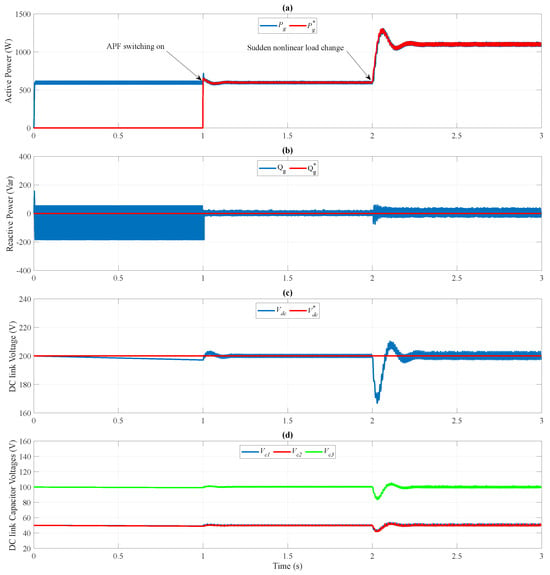
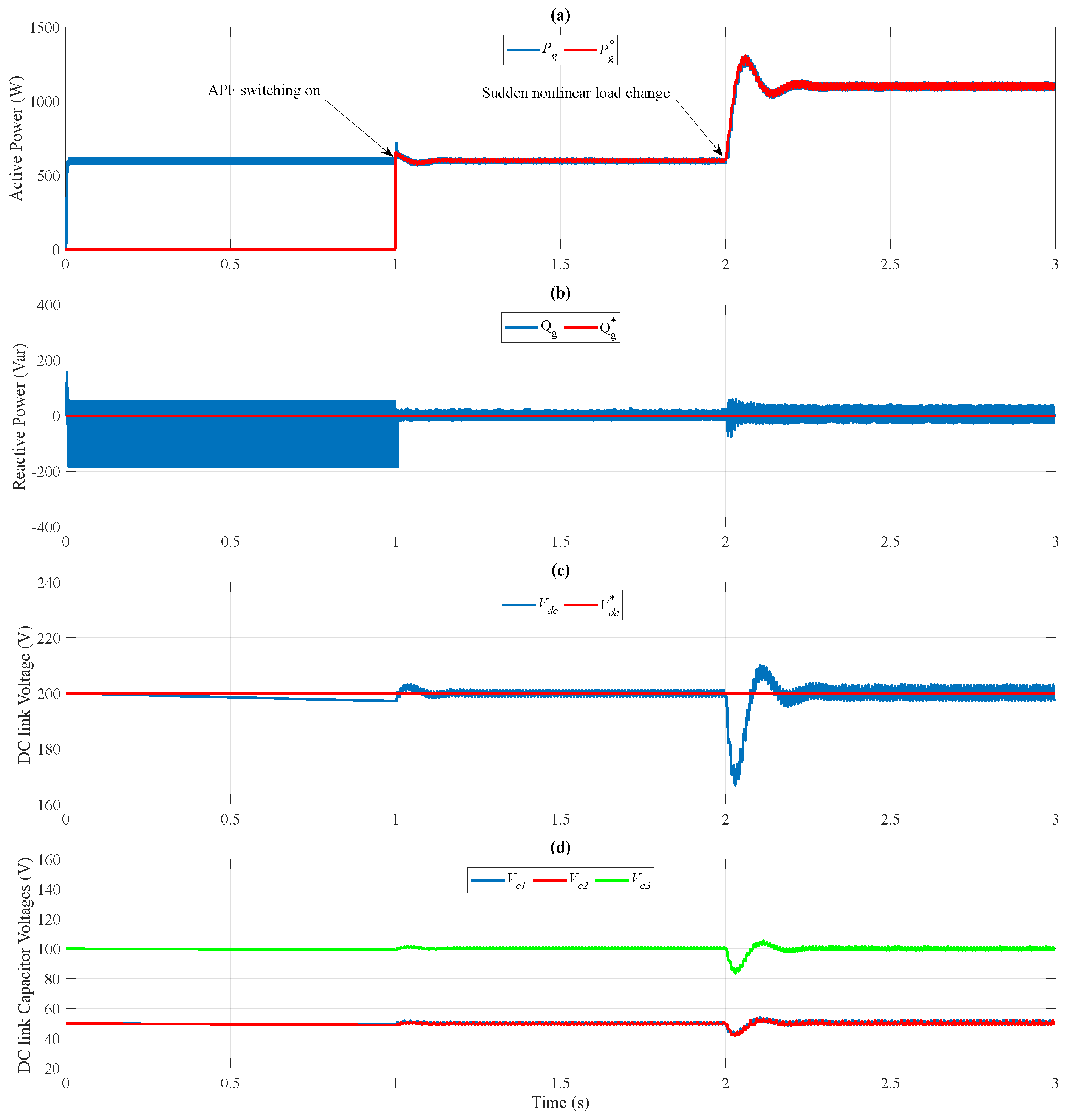
The results obtained for the proposed SAPF system are presented in Figure 6, Figure 7 and Figure 8. Figure 6 illustrates the evolution of the grid-side active and reactive powers, the total DC-bus voltage, and the individual DC-bus capacitor voltages. These waveforms provide an overview of the system’s power regulation and DC-bus voltage behavior during the evaluated operating conditions.
Figure 6.
PIL co-simulation waveforms for grid active and reactive powers, DC-bus voltage, and DC-bus capacitor voltages.
Figure 7.
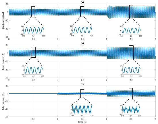
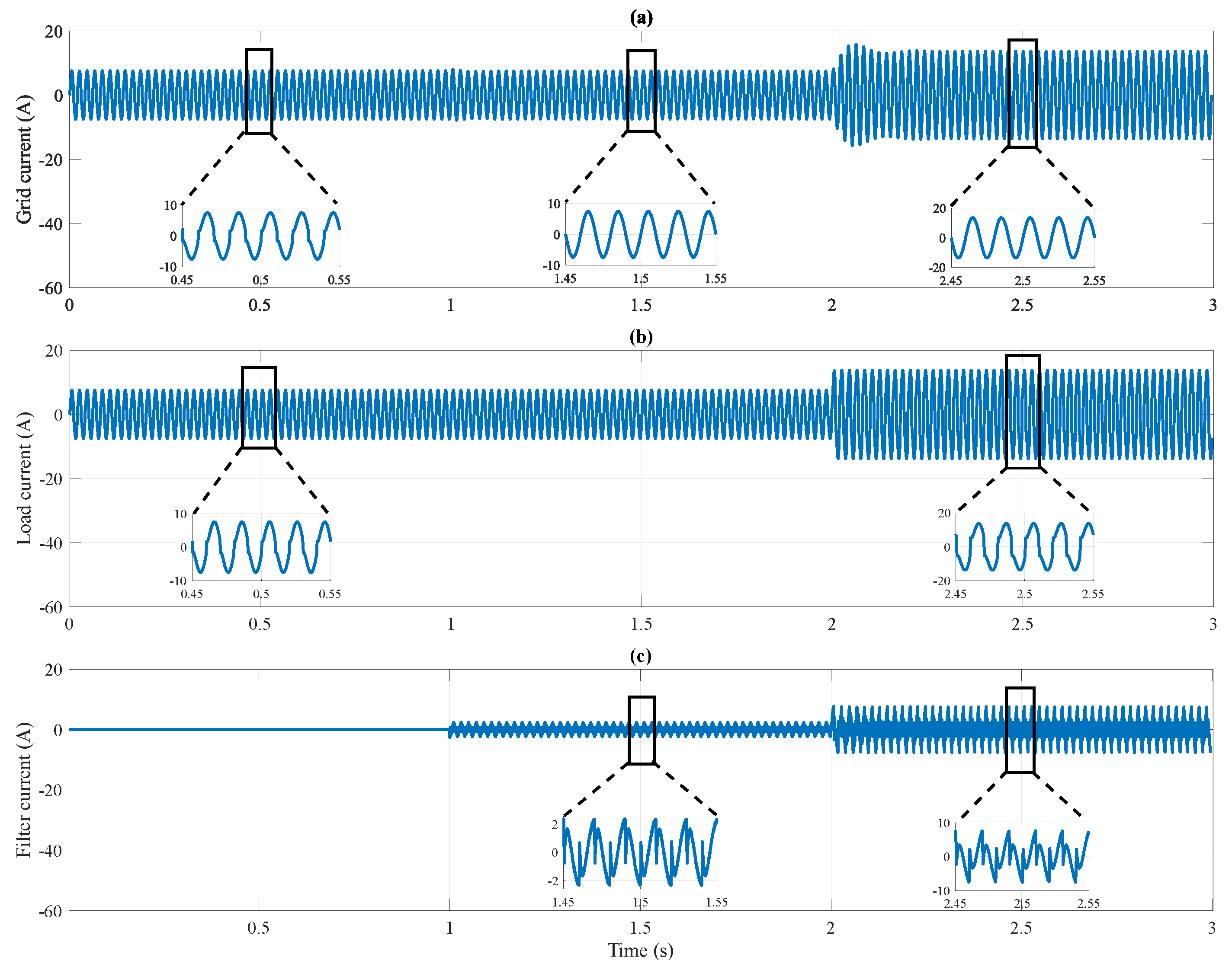
PIL co-simulation waveforms for grid current, load current, and filter current.
Figure 8.
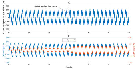
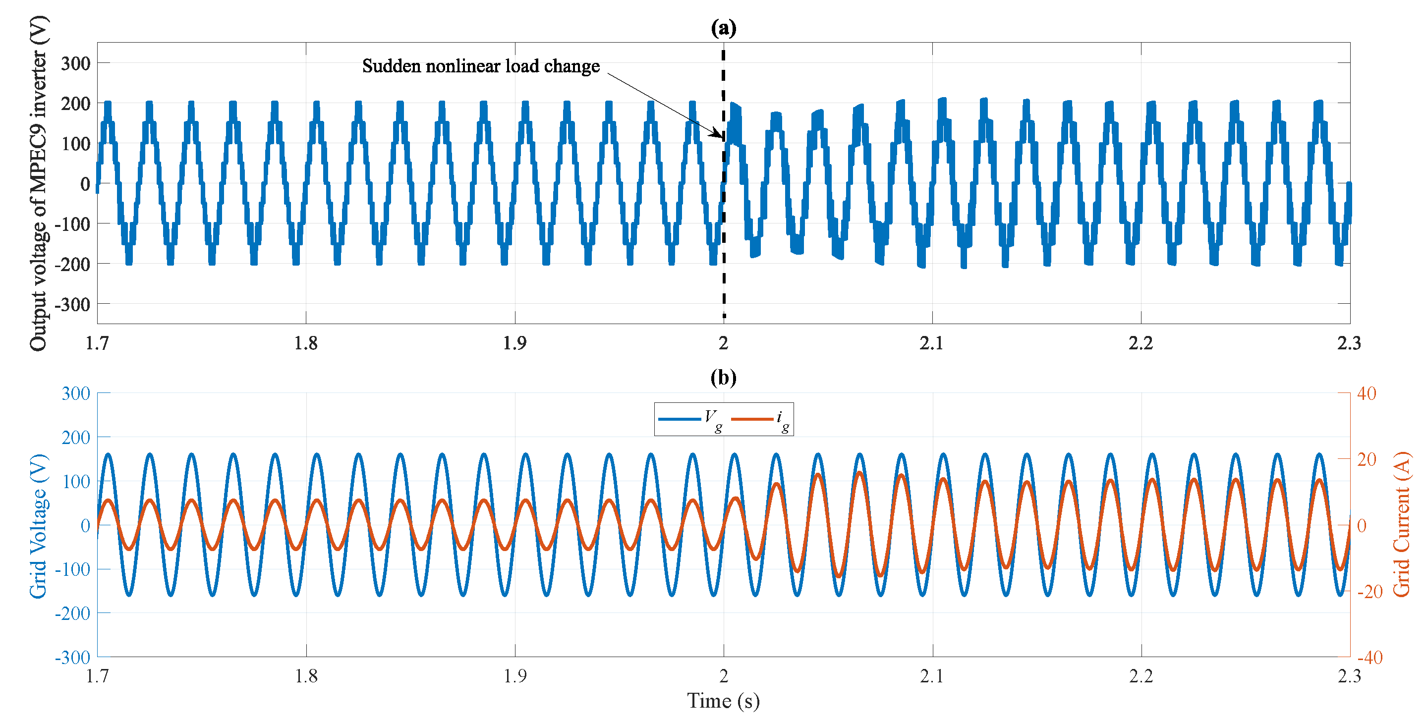
Zoom of output voltage of MPEC9 inverter, grid current, and grid voltage.
During the initial interval, the SAPF remains switched off, leaving the nonlinear load uncompensated. As shown in Figure 6a,b, the load draws active power from the grid while producing substantial reactive power fluctuations. This interval represents the uncompensated operating condition and provides a baseline for assessing the subsequent performance of the SAPF.
When the SAPF is in operation at , the grid active power follows its reference signal, which is the active power demanded by the nonlinear load. Meanwhile, the filter compensates the reactive power generated by the load and makes the grid-side reactive power close to zero. These results illustrate the system’s ability to meet the load’s active power requirements while reducing reactive power exchange with the grid.
The DC-bus capacitor voltages are successfully balanced, with and each maintained at half the value of as shown in Figure 6d, which means that the overall voltage regulation is done along with an even distribution of the voltage among the capacitors. Together, these responses demonstrate coordinated power compensation and DC-bus voltage regulation under the evaluated operating conditions.
Finally, a sudden change in the nonlinear load is introduced at , resulting in a higher reactive power demand. In response, the proposed DPC-SMPC strategy keeps the grid active power closely aligned with its reference and maintains the grid reactive power near zero. The DC-bus voltage also remains close to its reference, while the individual capacitor voltages stay balanced. These results highlight the controller’s ability to maintain the desired performance despite the abrupt load change, demonstrating its effectiveness and robustness under the evaluated operating conditions.
Figure 7 presents the waveforms of the grid current (), filter current (), and load current (). Before the MPEC9-based SAPF is activated, the grid current exhibits substantial harmonic distortion caused by the nonlinear load, as shown in Figure 7a. At , the SAPF is switched on and begins injecting a compensating harmonic current (), as illustrated in Figure 7c, thereby mitigating the load-induced harmonics in the grid current. Consequently, the grid current becomes nearly sinusoidal, as shown in Figure 7a. These results demonstrate the effectiveness of the proposed MPEC9-based SAPF employing DPC-SMPC in improving grid current quality.
At , the nonlinear load resistance is changed from 20 to 10 , accompanied by an increase in the peak load current, as shown in Figure 7b. Despite this load variation, the proposed DPC-SMPC maintains a nearly sinusoidal grid current, as illustrated in Figure 7a. These results demonstrate the fast dynamic response and robustness of the proposed control strategy under abrupt load changes.
Figure 8a presents the MPEC9 inverter output voltage during the sudden nonlinear load variation. The proposed DPC-SMPC rapidly restores the nine-level voltage waveform, demonstrating its fast transient response. As shown in Figure 8b, the grid current remains nearly sinusoidal and in phase with the grid voltage despite the load disturbance, indicating near-unity power factor operation under this transient condition. The grid current quality achieved by the proposed DPC-SMPC and the conventional DPC-MPC is evaluated through PIL co-simulation, with the results summarized in Table 3. The comparison shows that the proposed strategy achieves lower grid current total harmonic distortion (THD) than the conventional approach.
Table 3.
THD analysis of grid current.
The DPC-MPC required approximately 2.41 µs per control cycle, whereas the proposed DPC-SMPC required only 1.64 µs, corresponding to a 32.24% reduction in execution time. This measurement accounts for the complete execution of the proposed control algorithm, including the additional operations associated with the optimal voltage references and . These results demonstrate that the proposed DPC-SMPC substantially reduces the online computational time and improves the control performance compared with that of the DPC-SMPC.
6. Conclusions
This paper develops an MPEC9 inverter for a single-phase SAPF system. The proposed topology employs only six bidirectional active switches, one four-quadrant switch, and three capacitors. Furthermore, a DPC-SMPC scheme is proposed to regulate grid active and reactive power while balancing the bus capacitor voltages. In the proposed DPC-SMPC, the predicted macro-variable is used to calculate the optimal voltage vector corresponding to the grid active and reactive power references only once per sampling period. Next, the bus capacitor voltages are predicted for all feasible switching states and incorporated into the DPC-SMPC cost function with the optimal voltage vector. Processor-in-the-loop (PIL) co-simulation is conducted to shed light on the effectiveness of the suggested SAPF system with the novel DPC-SMPC. A comparison with the DPC-MPC proves that the proposed DPC-SMPC achieves all control objectives under several critical conditions while also reducing the computational burden. Accurate reactive power compensation is achieved, ensuring unity power factor operation. Furthermore, the bus capacitor voltages remain well balanced, and the MPEC9 inverter generates the nine-level output voltage waveform. Finally, the proposed DPC-SMPC achieves a lower grid current total harmonic distortion (THD) of 1.43% compared with 1.57% for the conventional DPC-MPC, demonstrating its superior steady-state performance. The proposed DPC-SMPC algorithm reduce the computational burden by 32.24% compared with the DPC-MPC algorithm. The later required approximately 2.41 µs per control cycle, whereas the proposed DPC-SMPC required only 1.64 µs. Thus, the proposed DPC-SMPC substantially decreases the online computational time and enhance the control performance compared with the DPC-MPC.
Author Contributions
Conceptualization, A.L.; Methodology, A.L., F.B., B.K. and S.N.; Software, A.L. and B.K.; Validation, A.L., F.B., B.K. and S.N.; Formal analysis, A.L., F.B. and S.N.; Investigation, A.L. and F.B.; Resources, A.L., F.B. and B.K.; Data Curation, A.L. and F.B.; Writing—Original Draft, A.L., F.B., B.K. and S.N.; Writing—Review and Editing, A.L., F.B. and B.K.; Visualization, B.K. and S.N.; Supervision, S.N. All authors have read and agreed to the published version of the manuscript.
Funding
This research received no external funding.
Data Availability Statement
The original contributions presented in this study are included in the article. Further inquiries can be directed to the corresponding author.
Conflicts of Interest
The authors declare no conflicts of interest.
References
- Sahli, A.; Krim, F.; Laib, A.; Talbi, B. Model predictive control for single phase active power filter using modified packed U-cell (MPUC5) converter. Electr. Power Syst. Res. 2020, 180, 106139. [Google Scholar] [CrossRef] [Scilit]
- Sahli, A.; Krim, F.; Laib, A.; Talbi, B. Energy management and power quality enhancement in grid-tied single-phase PV system using modified PUC converter. IET Renew. Power Gener. 2019, 13, 2512–2521. [Google Scholar] [CrossRef] [Scilit]
- Prakash, S.; Alkhatib, M.; Sindi, H.F.; Alghamdi, S.; Behera, R.K.; Muduli, U.R. Adaptive control for shunt active power filter under stochastic solar photovoltaics behavior. IEEE J. Emerg. Sel. Top. Power Electron. 2025, 13, 3673–3687. [Google Scholar] [CrossRef] [Scilit]
- Zhou, X.; Liu, Y.; Tao, L.; Wen, H. A harmonic suppression technology based on feedforward reference deviation compensation ADRC control for active power filters. Electr. Power Syst. Res. 2026, 251, 112269. [Google Scholar] [CrossRef] [Scilit]
- Uwagboe, J.O.; Saha, A.K. A comprehensive review of multilevel inverter topologies and control strategies for grid-connected photovoltaic battery energy storage systems integrating active power filter. IEEE Access 2025, 13, 169989–170016. [Google Scholar] [CrossRef] [Scilit]
- Raja, R.; Saravanan, R.; Ranjith Kumar, K.; Hannah Jessie Rani, R. Design and Control of Multi-Level Inverter-Based Shunt Active Power Filters Using BWKA-QSANN for Harmonic Mitigation in Dynamic Distribution Systems. J. Circuits Syst. Comput. 2026. [Google Scholar] [CrossRef] [Scilit]
- Durgalakshmi, K.; Kannapiran, B. Performance enhancement of shunt active power filter using advanced multilevel inverter driven by intelligent control strategy. Electr. Power Syst. Res. 2026, 256, 112849. [Google Scholar] [CrossRef] [Scilit]
- Toopchizadeh, H.; Zallaghi, M.; Moradi, M.; Shahmoradi, S. An effective shunt active power filter based on novel binary multilevel inverter and optimal type-2 fuzzy system to accurately mitigate harmonic currents. Evol. Syst. 2023, 14, 783–800. [Google Scholar] [CrossRef] [Scilit]
- Laib, A.; Krama, A.; Sahli, A.; Kihal, A.; Abu-Rub, H. Reconfigurable Model Predictive Control for Grid Connected PV Systems Using Thirteen-Level Packed E-Cell Inverter. IEEE Access 2022, 10, 102210–102222. [Google Scholar] [CrossRef] [Scilit]
- Babadi, A.N.; Salari, O.; Mojibian, M.J.; Bina, M.T. Modified multilevel inverters with reduced structures based on Packed U-cell. IEEE J. Emerg. Sel. Top. Power Electron. 2017, 6, 874–887. [Google Scholar] [CrossRef] [Scilit]
- Vahedi, H.; Sharifzadeh, M.; Al-Haddad, K. Modified seven-level packed U-cell inverter for photovoltaic applications. IEEE J. Emerg. Sel. Top. Power Electron. 2018, 6, 1508–1516. [Google Scholar] [CrossRef] [Scilit]
- Sharifzadeh, M.; Al-Haddad, K. Packed E-Cell (PEC) converter topology operation and experimental validation. IEEE Access 2019, 7, 93049–93061. [Google Scholar] [CrossRef] [Scilit]
- Laib, A.; Kanouni, B.; Necaibia, S.; Krama, A.; Chedjara, Z.; Su, C.L.; Ahmed, H. Novel finite-set synergetic mode predictive control of stand-alone renewable energy systems using LC-filtered nine-level packed E-cell inverter. In Proceedings of the 2025 IEEE Industry Applications Society Annual Meeting (IAS); IEEE: Piscataway, NJ, USA, 2025; pp. 1–6. [Google Scholar]
- Rahim, N.A.; Selvaraj, J. Multistring five-level inverter with novel PWM control scheme for PV application. IEEE Trans. Ind. Electron. 2009, 57, 2111–2123. [Google Scholar] [CrossRef] [Scilit]
- Rayane, K.; Bougrine, M.; Krama, A.; Benalia, A.; Trabelsi, M.; Abu-Rub, H. Average model-based feedforward and feedback control for PUC5 inverter. IEEE Access 2020, 8, 172962–172971. [Google Scholar] [CrossRef] [Scilit]
- Krama, A.; Refaat, S.S.; Abu-Rub, H. A robust second-order sliding mode control of sensorless five level packed U cell inverter. In Proceedings of the 46th Annual Conference of the IEEE Industrial Electronics Society; IEEE: Piscataway, NJ, USA, 2020; pp. 2412–2417. [Google Scholar]
- Aris, I.; Sadou, Y.; Laib, A. An Optimal Integral Fast Terminal Synergetic Control Scheme for a Grid-to-Vehicle and Vehicle-to-Grid Battery Electric Vehicle Charger Based on the Black-Winged Kite Algorithm. Energies 2025, 18, 3397. [Google Scholar] [CrossRef] [Scilit]
- Gupta, J.; Singh, B. A Cost Effective High Power Factor General Purpose Battery Charger for Electric Two-Wheelers and Three Wheelers. IEEE Trans. Consum. Electron. 2023, 69, 1114–1123. [Google Scholar] [CrossRef] [Scilit]
- Çelik, D.; Ahmed, H.; Meral, M.E. Kalman Filter-Based Super-Twisting Sliding Mode Control of Shunt Active Power Filter for Electric Vehicle Charging Station Applications. IEEE Trans. Power Deliv. 2022, 38, 1097–1107. [Google Scholar] [CrossRef] [Scilit]
- Rath, A.; Srungavarapu, G. An Advanced Shunt Active Power Filter (SAPF) for Non-Ideal Grid Using Predictive DPC. IETE Tech. Rev. 2023, 40, 521–534. [Google Scholar] [CrossRef] [Scilit]
- Rath, A.; Behera, B.P.; Sethi, B.K. Improved Shunt Active Filter for Non-Ideal Grid Using Model Predictive and Sliding Mode Control. IEEE Trans. Consum. Electron. 2024, 70, 6600–6608. [Google Scholar] [CrossRef] [Scilit]
- Laib, A.; Krim, F.; Talbi, B.; Feroura, H.; Kihal, A. Decoupled active and reactive power control strategy of grid-connected six-level diode-clamped inverters based on finite set model predictive control for photovoltaic application. Rev. Roum. Des Sci. Tech.-Ser. Electrotech. Et Energetique 2019, 64, 51–56. [Google Scholar]
- Annoukoubi, M.; Essadki, A.; Akarne, Y. Model Predictive Control of Multilevel Inverter Used in a Wind Energy Conversion System Application. e-Prime Electr. Eng. Electron. Energy 2024, 9, 100717. [Google Scholar] [CrossRef] [Scilit]
- Khallouf, K.N.; Benbouhenni, H.; Elbarbary, Z.M.S.; Laid, Z. Fractional-Order Predictive Direct Power Control for Hybrid Power Systems Based on Shunt Active Power Filters. Electr. Eng. 2026, 108, 257. [Google Scholar] [CrossRef] [Scilit]
- Bekakra, Y.; Zellouma, L.; Malik, O. Improved Predictive Direct Power Control of Shunt Active Power Filter Using GWO and ALO–Simulation and Experimental Study. Ain Shams Eng. J. 2021, 12, 3859–3877. [Google Scholar] [CrossRef] [Scilit]
- Essoussi, B.; Moutabir, A.; Bensassi, B.; Ouchatti, A.; Zahraoui, Y.; Benazza, B. Power Quality Improvement Using a New DPC Switching Table for a Three-Phase SAPF. Int. J. Robot. Control Syst. 2023, 3, 510–529. [Google Scholar] [CrossRef] [Scilit]
- Wu, X.; Yu, F.; Shao, Y. Simplified Model and Sliding Mode Control Method of Active Power Filter. In Proceedings of the 2025 International Conference on Power Electronics and Electric Drives (PEED); IEEE: Piscataway, NJ, USA, 2025; pp. 194–198. [Google Scholar]
- Pérez-Ramírez, J.; Montoya-Acevedo, D.; Gil-González, W.; Montoya, O.D.; Restrepo, C. Shunt Active Power Filter Using Model Predictive Control with Stability Guarantee. e-Prime-Adv. Electr. Eng. Electron. Energy 2025, 12, 101029. [Google Scholar] [CrossRef] [Scilit]
- Ibanez-Hidalgo, I.; Aguilera, R.P.; Sanchez-Ruiz, A.; Perez-Basante, A.; Zubizarreta, A.; Ceballos, S. Model Predictive Control Based Selective Harmonic Control-PWM Strategy for Active Power Filters. Int. J. Electr. Power Energy Syst. 2026, 175, 111576. [Google Scholar] [CrossRef] [Scilit]
- Trabelsi, M.; Bayhan, S.; Ghazi, K.A.; Abu-Rub, H.; Ben-Brahim, L. Finite-control-set model predictive control for grid-connected packed-U-cells multilevel inverter. IEEE Trans. Ind. Electron. 2016, 63, 7286–7295. [Google Scholar] [CrossRef] [Scilit]
- Rodriguez, J.; Kazmierkowski, M.P.; Espinoza, J.R.; Zanchetta, P.; Abu-Rub, H.; Young, H.A.; Rojas, C.A. State of the art of finite control set model predictive control in power electronics. IEEE Trans. Ind. Inform. 2012, 9, 1003–1016. [Google Scholar] [CrossRef] [Scilit]
- Bouzidi, M.; Barkat, S.; Krama, A.; Abu-Rub, H. Simplified predictive direct power control of three-phase three-level four-leg grid connected NPC converter. IEEE Open J. Ind. Electron. Soc. 2022, 3, 448–459. [Google Scholar] [CrossRef] [Scilit]
- Padhy, S.; Bhuyan, K.C.; Rath, A. Model predictive direct power control for shunt active power filter using adaptive back stepping control and unscented Kalman filter. Electr. Eng. 2026, 108, 260. [Google Scholar] [CrossRef] [Scilit]
- Padhy, S.; Bhuyan, K.C.; Rath, A. A novel simplified predictive approach with adaptive reactive power reference for shunt active power filters in non-ideal grids. Electr. Power Syst. Res. 2026, 251, 112273. [Google Scholar] [CrossRef] [Scilit]
- Xu, W.; Li, N.; Chen, Y. Continuous Control Set Model Predictive Control Method for Three-Level Active Power Filter Based on NN-RLS Parameter Identification. IEEE Access 2026, 14, 148677–148692. [Google Scholar] [CrossRef] [Scilit]
- Foster, J.G.; Ferreira, S.C.; Gonzatti, R.B.; Pereira, R.R.; Santos, Y.A. Finite control set model predictive control applied to multilevel hybrid active power filter. IEEE Trans. Ind. Electron. 2025, 72, 9532–9541. [Google Scholar] [CrossRef] [Scilit]
- Shadmand, M.B.; Li, X.; Balog, R.S.; Abu-Rub, H. Model predictive control of grid-tied photovoltaic systems: Maximum power point tracking and decoupled power control. In Proceedings of the 2015 First Workshop on Smart Grid and Renewable Energy; IEEE: Piscataway, NJ, USA, 2015; pp. 1–6. [Google Scholar]
- Santos Filho, R.M.; Seixas, P.F.; Cortizo, P.C.; Torres, L.A.B.; Souza, A.F. Comparison of three single-phase PLL algorithms for UPS applications. IEEE Trans. Ind. Electron. 2008, 55, 2923–2932. [Google Scholar] [CrossRef] [Scilit]
- Cortes, P.; Kouro, S.; La Rocca, B.; Vargas, R.; Rodriguez, J.; Leon, J.; Vazquez, S.; Franquelo, L. Guidelines for weighting factors design in model predictive control of power converters and drives. In Proceedings of the IEEE International Conference on Industrial Technology (ICIT), Gippsland, Australia, 10–13 February 2009; IEEE: Piscataway, NJ, USA, 2009; pp. 1–7. [Google Scholar]
- Ebrahim, M.A.; Aziz, B.A.; Nashed, M.N.; Osman, F.A. Optimal design of proportional-resonant controller and its harmonic compensators for grid-integrated renewable energy sources based three-phase voltage source inverters. IET Gener. Transm. Distrib. 2021, 15, 1371–1386. [Google Scholar] [CrossRef] [Scilit]

Disclaimer/Publisher’s Note: The statements, opinions and data contained in all publications are solely those of the individual author(s) and contributor(s) and not of MDPI and/or the editor(s). MDPI and/or the editor(s) disclaim responsibility for any injury to people or property resulting from any ideas, methods, instructions or products referred to in the content. |
© 2026 by the authors. Licensee MDPI, Basel, Switzerland. This article is an open access article distributed under the terms and conditions of the Creative Commons Attribution (CC BY) license.