


Abstract
Compressed air energy storage is a large-capacity, long-term physical energy storage technology. With the advantages of safety, environmental protection and long life, it is moving from demonstration to large-scale commercial application driven by policy support and global energy transformation. Aiming at the problem of structural stability of underground caverns in CAES, the existing research mostly focuses on the mechanical response of unreinforced lining under cyclic internal pressure and in-situ stress field. However, there is a lack of systematic comparative analysis on the long-term dynamic stability of lining reinforced with carbon fiber-reinforced polymer under different cavern burial depths, cavern radii and surrounding rock grades. In this paper, an analysis model considering elastic–plastic mechanical behavior and stability theory is established, and the improvement effect of CFRP reinforcement on the mechanical properties of a cavern lining is systematically evaluated. Firstly, based on the complex variable function method and elastic–plastic theory, the analytical solutions of stress-displacement field of surrounding rock-lining structure under reinforced and unreinforced conditions are derived, respectively. By introducing the CFRP constraint effect, the correction formula of the maximum allowable cyclic internal pressure amplitude to maintain the dynamic stability of the structure is proposed. The accuracy of the numerical simulation is verified by the theoretical model. The results of a parameter sensitivity analysis show that the buried depth of the cavern, the grade of the surrounding rock and the radius of the cavern are the key factors affecting the static stability and dynamic stability of the structure. Compared with the unreinforced condition, CFRP reinforcement reduces the displacement and modifies the stress field of the lining under unfavorable geological conditions. Furthermore, the ratio of in-situ stress to internal pressure considering the reinforcement effect is proposed as a dimensionless evaluation index for cavern layout optimization. The research results provide a theoretical basis and engineering guidance for lining selection and reinforcement design of CAES underground caverns under high stress and complex geological conditions. The present study is based on several idealizations, including a constant thermal condition, perfect interface bonding, and a zero-relaxation excavation-support sequence. These assumptions define the scope of the present mechanical analysis and should be validated in future work.
1. Introduction
In the context of the global response to climate change and the transformation of energy structure, the installed capacity of renewable energy represented by wind and solar energy has shown explosive growth [1]. However, the inherent intermittency and instability of renewable energy pose a serious challenge to the safe and stable operation of power systems [2]. As a key means to solve this bottleneck problem, energy storage technology can realize the space-time translation of energy, so as to optimize the balance of supply and demand [3]. Among many large-scale energy storage technologies, compressed air energy storage is regarded as one of the key technologies to support the development of renewable energy because of its large energy storage capacity, environmental friendliness, relatively low cost and long service life [4,5].
A typical CAES system uses low-valley electricity or abandoned wind or abandoned photoelectric compressed air and stores it in an underground salt cavern or artificial container, releasing high-pressure air to drive a turbine to generate electricity during peak electricity consumption [6,7,8,9]. However, the traditional CAES system usually adopts the constant volume gas storage mode; that is, the volume of the gas storage cave is fixed [10]. In the discharge process, in order to ensure the stability of the turbine inlet pressure, the high-pressure air needs to be throttled and depressurized, resulting in a large amount of high-pressure air remaining in the cave, low effective gas storage density, and poor utilization of gas storage space [11]. Studies have shown that, in large-scale CAES projects, the investment cost of artificial gas storage containers can account for about 40% of the total cost [12]. In order to cope with this challenge, the CAES system based on variable volume gas storage came into being. This technology realizes the complete release of air by volume replacement, which significantly improves the utilization rate of gas storage space and reduces the cost of gas storage. At the same time, it can achieve isobaric release and obtain higher round-trip efficiency [13].
In the practice of underground CAES engineering, the stability of the gas storage cavern is the core factor in determining the success or failure of the project. Whether it is traditional constant volume gas storage or new variable volume gas storage, artificial caverns need to withstand several megapas cyclic pressure loads and complex in-situ stress. Salt caverns are currently the most ideal gas storage medium due to their natural low permeability and self-healing properties. Both Huntorf and McIntosh commercial power stations use such salt caverns, but the scheme is severely limited by geographical distribution [14]. For the widely distributed non-salt rock strata, the use of lining closed artificial caverns has become the main technical route, and its air tightness depends on the sealing layer composed of steel, composite materials or polymer membranes [15]. The research of Bu et al. [16] shows that the abandoned mine roadway can be used as CAES gas storage space after transformation, which further expands the geological adaptability.
In this kind of structure, the lining and surrounding rock together constitute the bearing system, and its long-term stability is affected by the coupling of multiple factors such as cyclic internal pressure, in-situ stress level and mechanical properties of the surrounding rock. Khaledi et al. [17] and Menendez et al. [18] studied the thermal–mechanical response of rock salt caverns under cyclic high-pressure storage conditions through numerical simulation and found that the rapid fluctuation of temperature and pressure will significantly affect the damage evolution and permeability change of surrounding rock. Kushnir et al. [19] further pointed out that daily or hourly cycle conditions can induce microcrack propagation, which ultimately affects the service life of the cave. For lining rock caverns, Jiang et al. [20] verified its mechanical behavior under high internal pressure through small-scale model tests, while Schmidt et al. [21] discussed the technical feasibility of building lining tunnels in abandoned coal mines. In addition, when high-pressure air is in direct contact with water to achieve hydrostatic pressure compensation, air dissolution leads to gas loss and increases the risk of oxygen corrosion, which is one of the key issues facing Hydrostor ‘s large-scale demonstration projects in Australia and the United States [22,23,24,25].
Recent research has advanced the understanding of mechanical performance for CAES lined rock caverns under cyclic high-pressure operation. Liu et al. investigated long-term deformation and damage accumulation of rock cavern liners subjected to repeated charge–discharge cycles [26]. Fiber-reinforced polymer composite linings have attracted attention to mitigate tensile cracking of concrete liners for underground CAES caverns [27]. Analytical–numerical solutions have also been developed to describe rock-lining elastoplastic interaction under high internal air pressure [28]. However, most of the current studies focus on the mechanical response of unreinforced lining under monotonic or cyclic loading. There is still a lack of systematic theoretical analysis and comparative study on the dynamic stability and damage evolution of lining structures under different geological conditions after reinforcement with high-performance composite materials [29,30,31]. With its ultra-high tensile strength, high elastic modulus and excellent fatigue resistance, carbon fiber cloth has been widely used in the field of structural reinforcement. Therefore, the introduction of CFRP into the CAES underground cavern lining to form a steel lining, CFRP, and reinforced concrete composite lining system is expected to modify the load transfer path and reduce the displacement of the structure under unfavorable geological conditions.
In view of this, aiming at the stability problem of CAES underground artificial caverns, this paper establishes an analysis model that comprehensively considers elastic–plastic mechanical behavior and stability theory and systematically evaluates the improvement effect of CFRP reinforcement on the mechanical properties of the lining. Firstly, based on the complex variable function method and elastic–plastic theory, the analytical solutions of the stress and displacement field of the surrounding rock lining structure under reinforced and unreinforced conditions are derived, respectively [32], and the CFRP constraint effect is introduced to propose a correction formula for the maximum allowable cyclic internal pressure amplitude to maintain the dynamic stability of the structure. Then, through finite-difference method numerical simulation, the influence of CFRP reinforcement on the displacement of surrounding rock, the internal force of lining and the evolution of the plastic zone are compared and analyzed under the conditions of different buried depths, radii and grades of surrounding rock. The purpose of this study is to reveal the mechanical role of CFRP reinforcement in the surrounding rock-lining composite structure and to provide a theoretical basis for lining selection and reinforcement design of CAES underground cavern under high stress and complex geological conditions. The present study is limited to the prescribed plane-strain and isothermal conditions, and the conclusions should be interpreted within this scope.
2. Theoretical Analysis
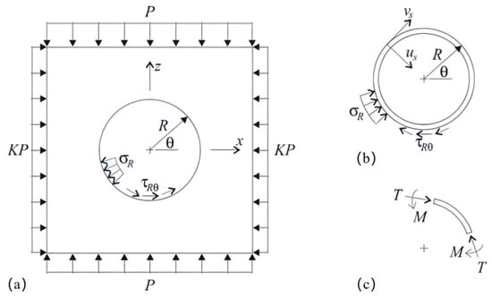
The stability of compressed air energy storage caverns mainly depends on the synergistic interaction between the surrounding rock and the lining. In this paper, according to the mechanism of action between the surrounding rock and lining, such as the mechanical model of Figure 1, the model is composed of surrounding rock, lining and gas storage space from outside to inside. The load P acting on the upper and lower parts of the boundary is mainly derived from the gravity of the overlying strata [33]. The lateral load KP acting on the side is mainly derived from the weight of rock and soil. The main influencing factors are the mechanical properties of rock and soil. The larger the Poisson‘s ratio, the easier the lateral expansion under vertical pressure and the greater the lateral pressure. Cohesion and internal friction angle also determine the ability of soil to resist lateral deformation. In this study, the stress state of the surrounding rock is basically consistent with the in-situ stress state. The main influencing factors of the vertical stress of the vertical load are rock and soil weight and thickness. The horizontal stress of the lateral load is the product of the lateral stress coefficient K and the vertical stress. In this numerical simulation, the lateral stress coefficient is 1.48, which is taken from the on-site measurement report of the compressed air energy storage cavern project. This parameter is used only as the in-situ stress input for the present simulation. The original measured dataset is not used for model validation in this study.
Figure 1.
Mechanical model of surrounding rock lining. (a) Mechanical model of surrounding rock lining; (b) tunnel lining stress; (c) lining internal stress.
As shown in Figure 1, the inner wall of the compressed air energy storage artificial cavern bears the pressure of filling and discharging gas. In the present mechanical model, temperature and viscosity variations associated with air compression are not explicitly coupled to the mechanical field. This is treated as a modeling boundary condition rather than as an assumption validated by experimental data. Accordingly, the present simulations are restricted to the pressure-driven mechanical response under the prescribed thermal condition. The surrounding rock–lining interface is explicitly represented, and the stress state is evaluated under plane-strain conditions. It is assumed that the support and excavation are installed simultaneously in a pre-existing anisotropic biaxial stress field. Because the present study does not include a staged-construction analysis or field monitoring data, this assumption is interpreted as an idealized zero-relaxation end-member rather than as a direct representation of the actual excavation sequence. This assumption is conservative for the initial compressive stress in the lining but may be non-conservative for the tensile stress during pressurization. This distinction is important when interpreting the calculated lining forces and CFRP contribution. In addition, when the interface produces friction, the friction coefficient μ is taken as 0, 0.2, 0.4, 0.6, 0.8 and 1.0. In the baseline model, the interface between CFRP, steel and concrete is assumed to be perfectly bonded (coupling-cohesion-shear = 120). This assumption is more appropriate for good-quality rock (grades I–III) and may not hold for weaker rock (grades IV–V). The influence of interface friction on the peak stress of the sealing steel liner is observed in the parameter study; the effect becomes less pronounced when μ > 0.5.
2.1. Theoretical Assumptions and Boundary Conditions
In order to meet the theoretical assumptions of mechanical conditions, and because the actual operating conditions of the compressed air energy storage system are more complex, this study simplifies and abstracts the lining structure of the surrounding rock of the artificial cavern of the compressed air energy storage, so that it can better perform numerical simulation calculations. The specific assumptions are as follows:
- (1)
- Surrounding rock, concrete lining and steel lining are assumed to be elastic, continuous and isotropic materials. Although the assumptions of the ideal materials of various structures are relatively simple, the assumptions are less, and the reliability of the mechanical calculation results of the compressed air energy storage system is higher;
- (2)
- It is assumed that the artificial cavern section of the gas storage is a standard circular section, and the longitudinal size of the gas storage is much larger than the transverse size;
- (3)
- The lining is assumed to be a closed structure, and its outer radius is equal to the excavation radius of the cavern. Excavation and lining installation are assumed to occur simultaneously, so that no excavation-induced stress relaxation is introduced before support activation. This assumption is used as an idealized zero-relaxation limiting case for the mechanical comparison between unreinforced and CFRP-reinforced linings. It is conservative for the initial compressive stress in the lining but may be non-conservative for the tensile stress during pressurization. Since no staged excavation calculations or field convergence measurements are available in the present study, the effect of the construction sequence remains outside the validated scope of the model;
- (4)
- Assuming that the surrounding rock and the lining keep perfect contact, the relative position of the composite structure in the deformation process remains unchanged. That is, there is no shear stress transfer;
- (5)
- The present calculations impose a constant thermal condition and therefore exclude the temperature-dependent thermal strain and thermal stress generated during charging and discharging. No temperature history or coupled thermo-mechanical calculation is available in the present dataset to quantitatively calibrate this simplification. The conclusions of this study should therefore be interpreted as describing the mechanical response to cyclic air pressure at the prescribed isothermal condition, rather than the full thermo-mechanical response of a CAES cavern. Differential thermal expansion between CFRP, steel and concrete could alter local interface stresses and adhesive behavior. The thermal sensitivity of the CFRP-reinforced lining should be evaluated in future work using measured or thermodynamically predicted temperature histories.
2.2. Analytical Solution of Surrounding Rock Lining Structure
The analytical solution is expressed by the mechanical model of the surrounding rock lining in Figure 1. The support displacement consists of a radial direction us and a tangent vs component. The internal stress consists of an axial thrust T and a bending moment M. The interface contact stress is from the normal σR and the shear τRθ components.
There is no slip solution, and the interface boundary conditions include no relative shear displacement between the foundation and the support. The slip-free solution is given by the following equation:
where θ denotes the angle position, relative to the horizontal direction counterclockwise, R denotes the tunnel radius, P denotes the vertical stress, K denotes the ratio of horizontal stress and vertical stress, E denotes the Young‘s modulus, v denotes the Poisson‘s ratio, and , , denotes the dimensionless coefficient; see the following equation.
where C* and F* denote the compression ratio and the flexibility ratio, respectively.
Among them, Es represents the Young‘s support modulus, νs represents the support ratio of Poisson, As represents the average cross-sectional support area per unit tunnel length, for a constant thickness of the support t, As = t, Is represents the support moment of inertia per unit tunnel length, for a constant thickness of the support t, Is = t3/12.
The pressure terms used in this study are defined as follows: Pmax = 10 Mpa, Pmin = 4 Mpa, Pmean = 7 Mpa, Pamplitude = 3 Mpa, and ΔP = 6 Mpa. The correction formula for the maximum allowable cyclic internal pressure amplitude uses Pamplitude = 3 Mpa. The allowable cyclic internal pressure amplitude corresponds to the smaller of two criteria: (i) first yield of the steel liner and (ii) reaching the allowable strain of the CFRP layer. When the CFRP thickness tCFRP→0, the correction factor approaches 1, and the formula returns the unreinforced solution.
3. Numerical Modeling
σR In this chapter, a finite-difference model is implemented in FLAC3D 7.0 to reproduce the two-dimensional plane-strain mechanical problem described by the analytical solution and to maintain the same material layering and interface treatment used for the CFRP comparison. The numerical domain has dimensions of 100 m × 1 m × 200 m, with a 1 m thickness in the out-of-plane direction. At the boundary of the model, a uniform vertical load P is applied at the top and bottom of the model, and a uniform horizontal load KP is applied on both sides to simulate the stress state under non-hydrostatic pressure. The stress on the inner wall of the cavern is used to represent the gas pressure during charging and discharging. The model is therefore not a full three-dimensional simulation in the sense of resolving longitudinal end effects or spatially varying cavern geometry. Instead, FLAC3D is used as the numerical implementation platform for a plane-strain representation, with the 1 m out-of-plane thickness and symmetric boundary conditions enforcing the intended kinematic constraint. A conventional 2D plane-strain model could reproduce the same idealized cross-sectional mechanics. FLAC3D 7.0 is selected here because it uses an explicit finite-difference algorithm that is well-suited to nonlinear and plastic geotechnical problems, and because it provides built-in Mohr–Coulomb constitutive models, interface elements and structural elements that allow the surrounding rock, concrete lining, steel liner and CFRP layer to be represented within one numerical framework. The software is a three-dimensional solver; in this study, a single-layer mesh with symmetric boundary conditions is used to realize a plane-strain-equivalent two-dimensional simulation. This implementation also provides a direct path for future extension to staged construction, non-uniform longitudinal loading and fully three-dimensional effects.
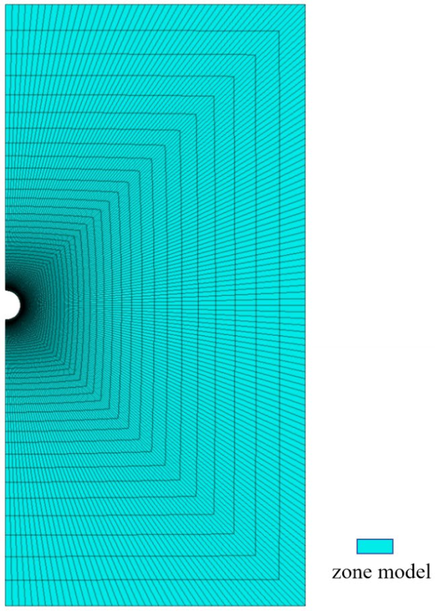
The finite-difference model represents a circular artificial cavern under an anisotropic biaxial stress field and plane-strain conditions. The in-situ stress is installed in all regions and acts on the far-field boundary. Symmetric boundary conditions are applied to the two surfaces normal to the out-of-plane direction, and the in-plane symmetry conditions constrain the normal displacement and rotation of the corresponding grid points. The grid contains a single layer in the out-of-plane direction and is gradually graded away from the cavern. The model resolution is 90 regions along the cavern boundary. Lining structural members are attached along the cavern boundary. A region-adaptive mesh refinement strategy is adopted, with finer elements around the cavern and coarser elements in the outer region. A region-adaptive mesh refinement strategy is adopted, with finer elements around the cavern and coarser elements in the outer region.The mesh resolution is 90 regions along the cavern boundary, and the radial grading ratio is 1.1 (Figure 2). The maximum unbalanced force is used as the main convergence criterion. Due to computational resource constraints, a full coarse–medium–fine mesh convergence study is not performed in the present study. This limitation is stated in the discussion section. Due to computational resource constraints, a full coarse-medium-fine mesh convergence study is not performed in the present study. This limitation is stated in the discussion section. The surrounding rock is modeled as an elastic–plastic material, and the Mohr–Coulomb criterion is used to describe the plastic zone. Two paired structural models, with and without CFRP, are analyzed under the same geometry, loading and material parameters so that the reinforcement effect can be isolated by direct comparison.
Figure 2.
Model grid schematic diagram.
The engineering background of this study is the research on the key technology of compressed air energy storage in underground shallow artificial caverns of the North China Branch of China Petroleum Engineering Construction Co., Ltd., and the technical project of surrounding rock stability analysis of underground caverns with compressed air energy storage is carried out. The project uses artificial caves as compressed air energy storage structures. The specific engineering parameters are shown in Table 1, Table 2, Table 3, Table 4 and Table 5.
Table 1.
Numerical simulation of underground cavern of compressed air energy storage, the example of cavern diameter affecting operation parameters.
Table 2.
Compressed air energy storage underground cavern value simulation cavern buried depth influence operation parameter example.
Table 3.
Compressed air energy storage underground cavern value simulation; cavern surrounding rock grade influence operation parameter example.
Table 4.
Design parameters of each material layer of underground cavern lining for compressed air energy storage.
Table 5.
Stacking sequence of CFRP composite ply system.
4. Mechanical Analysis and Analysis of Influencing Factors
In order to systematically reveal the regulation mechanism of the CFRP-reinforced layer on the mechanical properties of the composite surrounding rock-lining structure, two paired numerical models, unreinforced and CFRP-reinforced, are compared under identical geometry, boundary conditions and loading paths. In addition to displacement and plastic-zone evolution, the revised analysis explicitly compares the mechanical fields with and without CFRP using (i) the peak circumferential stress in the surrounding rock, (ii) the circumferential axial-force contribution carried by CFRP, and (iii) the surrounding-rock load-sharing ratio. For a given section, the CFRP axial-force share is expressed as φ_CFRP = N_CFRP/(N_CFRP + N_steel + N_RC), while the surrounding-rock load-sharing ratio is expressed as η_SR = Q_SR/Q_total. These paired quantities provide a direct basis for identifying whether the observed reduction in deformation and local stress concentration is accompanied by an actual redistribution of load to CFRP and the surrounding rock, rather than attributing the improvement only to the high stiffness of CFRP.
The quantities φ_CFRP and η_SR are defined at the section level. Q_total is the total circumferential force per unit length at a given section, obtained by integrating the circumferential stress over the lining cross-section. Q_SR is the portion of this force carried by the surrounding rock, obtained by integrating the radial contact stress at the rock-lining interface. The simple membrane estimate N = pR is not directly comparable because it neglects the bending stiffness of the composite lining and the load carried by the surrounding rock. Due to computational resource constraints, the integral quantities Q_total, Q_SR, Q_lining and Q_ CFRP are not calculated in the present study. This limitation is stated in the discussion section.
4.1. Analysis of the Influence of Cavern Diameter
As the core geometric parameter, the diameter of the cavern directly affects the circumferential tension level and stress concentration of the lining structure under alternating internal pressure. In this study, under the condition of surrounding rock grade III and buried depth of 100 m, the mechanical responses of caverns with diameters of 8 m, 10 m, 12 m, 15 m and 20 m with or without CFRP reinforcement were compared and analyzed.
4.1.1. Displacement Response Characteristics of Surrounding Rock
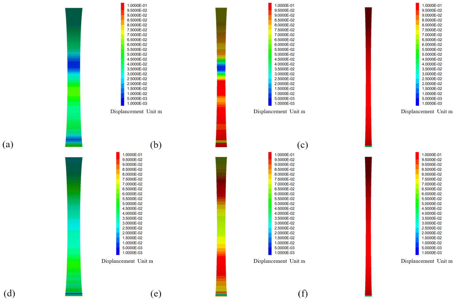
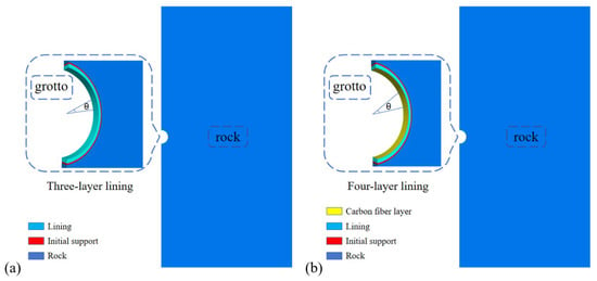
The simulation results show that the diameter of the cavern is significantly positively correlated with the displacement of the surrounding rock. Taking the 10 MPa inflation condition as an example, under the condition of unreinforced lining, the vault displacement of the chamber increases nonlinearly with the increase in diameter. The displacement is 0.08 mm when the diameter is 8 m and increases to 0.5 mm when the diameter is 20 m. After adding the CFRP layer, the displacement of each diameter chamber is reduced. In the chamber with a diameter of 15 m, the CFRP layer reduces the vault displacement from 0.30 mm to 0.25 mm, a decrease of 16.7%. In the chamber with a diameter of 20 m, the displacement is reduced from 0.50 mm to 0.45 mm, a decrease of 10%. For the 8 m diameter cavern, the displacement reduction is 0.005 mm, which is smaller than the estimated numerical uncertainty of 0.006 mm (3σ). Therefore, the improvement in this case is not considered statistically significant. For the 15 m and 20 m diameter caverns, the reductions are 0.05 mm and 0.05 mm, respectively, both of which exceed the estimated uncertainty, as shown in Figure 3. This phenomenon shows that the CFRP layer actively shares the circumferential tension of the lining structure by virtue of its high tensile strength and high elastic modulus, thus effectively restraining the radial deformation.
Figure 3.
Numerical simulation model of surrounding rock lining structure. (a) Lining model without carbon fiber support. (b) Lining model with carbon fiber support.
From the perspective of stress distribution characteristics, the CFRP layer significantly improves the stress state of the surrounding rock by reshaping the force flow path. Taking the 12 m diameter chamber as an example, under the unreinforced condition, the circumferential tensile stress of the surrounding rock is obviously concentrated near the waist of the chamber, θ = 0° and 180°, and the peak elastic circumferential stress is about 11 MPa. It should be noted that this value is obtained from the analytical elastic solution and represents the mechanical demand on the lining system before plastic yielding. In the numerical model, the surrounding rock is described by the Mohr–Coulomb criterion with a tension cut-off, and the actual tensile stress is limited by the tensile strength c/tanφ. For grade III rock with c = 1.1 MPa and φ = 45°, the tensile strength is 1.1 MPa. After adding the CFRP layer, the circumferential tensile stress distribution tends to be more uniform, and the peak elastic stress is reduced by about 18%(Figure 4). This phenomenon conforms to the basic principle of the adjustment of the principal stress direction in the elastic theory; that is, the CFRP layer optimizes the load transfer path between the surrounding rock and the lining through its anisotropic stiffness characteristics.
Figure 4.
Comparison of displacement contours of carbon fiber lining with or without different diameters. (a) No carbon fiber lining with a diameter of 8 m, (b) no carbon fiber lining with a diameter of 12 m, (c) no carbon fiber lining with a diameter of 20 m, (d) no carbon fiber lining with a diameter of 8 m, (e) no carbon fiber lining with a diameter of 12 m, (f) no carbon fiber lining with a diameter of 20 m.
4.1.2. Internal Force Redistribution Mechanism of Lining
The addition of a CFRP layer significantly changes the axial-force distribution of the lining structure. Under the unreinforced condition, the axial-force distribution of the steel sealing layer is concentrated locally, especially in the waist region of the cavern. After adding CFRP, the circumferential axial-force demand carried by the original lining system is reduced because part of the force is transferred to the CFRP layer. For the 10 m diameter reference cavern, the CFRP layer carries a significant share of the circumferential axial force. The observed share is in the range of 30–50% at the section level. This range is a local, section-level observation and does not represent a global average. The higher share compared with a simple elastic strain-compatibility estimate arises because the concrete layer cracks in tension, reducing its effective stiffness and redistributing the circumferential force to the CFRP and steel layers. Due to computational resource constraints, the absolute axial forces and strains of each layer are not extracted in the present study. This limitation is stated in the discussion section. The surrounding-rock stress field is also directly affected: for the 12 m diameter cavern, the peak circumferential tensile stress in the surrounding rock is about 11 MPa without CFRP and is reduced by approximately 18% after CFRP reinforcement. These paired results provide direct evidence that CFRP changes both the local stress field and the load path. They therefore support the interpretation that the reduction in lining demand is associated with load redistribution rather than displacement restraint alone. The reduced tensile demand in the reinforced concrete lining also provides a mechanical basis for the observed reduction in cracking risk.
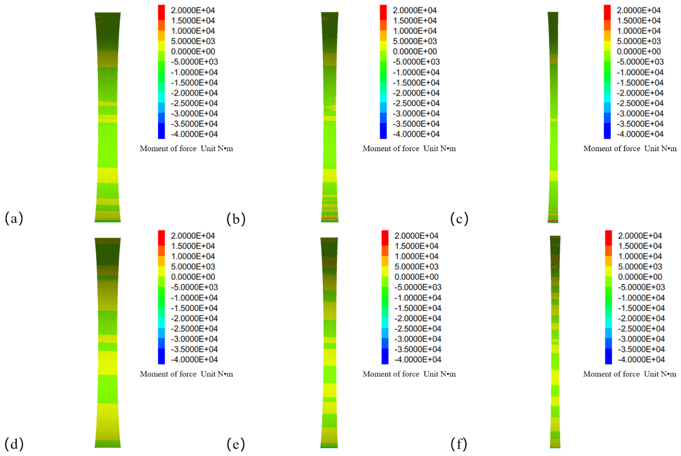
The bending-moment response requires a more cautious interpretation than the axial-force response. The paired results in Figure 5 and Figure 6 show that the locations of the dominant bending-moment peaks remain near the vault and inverted arch, while the reinforced profiles exhibit a reduced peak-to-peak contrast. However, because the present manuscript does not contain the full circumferential numerical data used to reconstruct M(θ), a precise coefficient of bending-moment uniformity cannot be independently calculated from the reported figures alone. The present conclusion is therefore limited to the observed reduction in peak bending moment in the paired numerical fields. The uniformity index UM = (Mmax − Mmin)/|Mmean| is not used because it becomes numerically unstable when the mean bending moment approaches zero. Due to computational resource constraints, the full circumferential M(θ)dataset is not extracted in the present study. This limitation is stated in the discussion section. Therefore, the revised manuscript does not treat visual smoothness of the contour as a quantitative proof of homogenization. Instead, the result is interpreted as a reduction in the spatial concentration of bending moment accompanying the redistribution of axial force to the CFRP layer. To make the CFRP mechanism directly testable, the reported paired simulations are consolidated in Table 6. Values that can be calculated from the reported percentage reduction are explicitly identified as derived values; where only a reduction ratio is available, the response is normalized to 100% for the unreinforced case.
Table 6.
Quantitative paired comparison of stress redistribution and CFRP contribution in representative cases.
For the bending-moment response, the revised analysis separates directly reported numerical evidence from observations that can only be interpreted qualitatively in Table 7. The manuscript reports that the vault bending moment at 200 m burial depth is about 25% higher than that at 50 m under the unreinforced condition. The absolute circumferential M(θ) data for the CFRP and unreinforced cases are not tabulated in the manuscript; therefore, a numerical homogenization coefficient is not fabricated. For subsequent numerical post-processing, the peak-to-mean concentration index UM = (Mmax − Mmin)/|Mmean| may be used, with a lower U_M indicating a less concentrated bending-moment field.
Table 7.
Numerical evidence and interpretation for bending-moment redistribution.
From the analysis of the mechanical mechanism, under the action of constant internal pressure Q, the circumferential axial force Nθ of the lining is proportional to the radius R of the cavern, that is, Nθ = Q · R. The increase of diameter leads to a significant increase in circumferential tension, which puts forward higher requirements for the tensile properties of lining materials. The tensile strength of concrete is about 2–4 MPa, which is easy to crack under a large tensile force. The tensile strength of CFRP is greater than 3400 MPa, which is much higher than that of concrete. It can bear 30–50% of the circumferential axial force, which effectively makes up for the mechanical short slab of large diameter cavern.
Based on the above analysis, under the premise of meeting the demand of gas storage capacity, the layout strategy of small diameter and multi-cavity combined with CFRP composite lining reinforcement is the optimization direction to achieve structural stability and economic balance.
Figure 5.
Comparison of axial force of carbon fiber lining with or without different diameters. (a) No carbon fiber lining with a diameter of 8 m, (b) no carbon fiber lining with a diameter of 12 m, (c) no carbon fiber lining with a diameter of 20 m, (d) no carbon fiber lining with a diameter of 8 m, (e) no carbon fiber lining with a diameter of 12 m, (f) no carbon fiber lining with a diameter of 20 m.
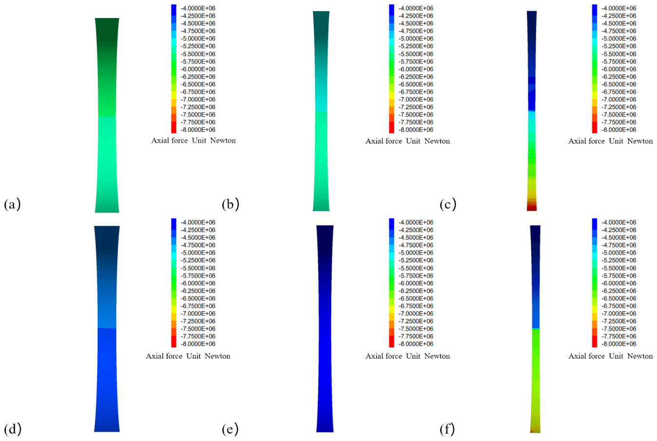
Figure 6.
Comparison of bending moment of carbon fiber lining with different diameters. (a) No carbon fiber lining with a diameter of 8 m, (b) no carbon fiber lining with a diameter of 12 m, (c) no carbon fiber lining with a diameter of 20 m, (d) no carbon fiber lining with a diameter of 8 m, (e) no carbon fiber lining with a diameter of 12 m, (f) no carbon fiber lining with a diameter of 20 m.
4.2. Analysis of the Influence of Buried Depth of Cavern
The buried depth directly determines the in-situ stress level and is the core environmental factor affecting the stability of CAES caverns. In this study, the structural response of CFRP layer with or without CFRP layer at 50 m, 100 m, 150 m, 200 m and 250 m buried depth was compared and analyzed under the condition of cavern diameter of 10 m and surrounding rock grade III.
4.2.1. Coupling Effect of In-Situ Stress and Internal Pressure
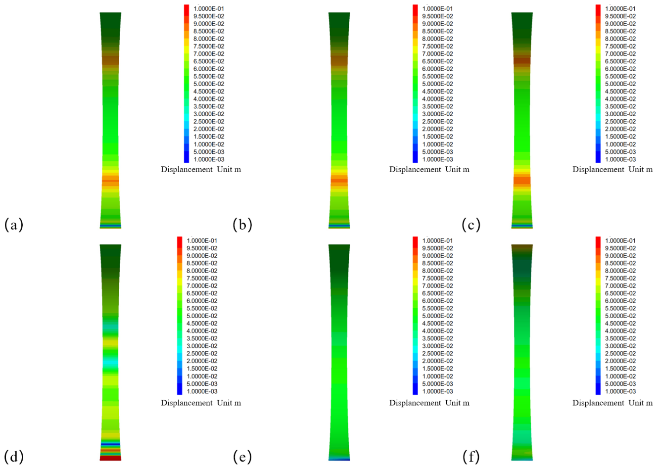
The simulation results show that, under the unreinforced condition, as the buried depth increases from 50 m to 250 m, the vault displacement of the cavern fluctuates slightly from 0.13 mm to 0.10 mm under the internal pressure of 10 MPa and does not show a monotonic increasing trend. This phenomenon shows that there is a mutual competition mechanism between the constraint effect of ground stress on deformation and the expansion deformation caused by internal pressure. Under the shallow buried condition of 50 m, the in-situ stress level is lower, the vertical stress is 1.25 MPa, the internal pressure is dominant, and the displacement is relatively large. Under the deep buried condition of 250 m, the vertical stress reaches 6.25 MPa, and the constraint effect of surrounding rock on lining is significantly enhanced, which partially offsets the expansion effect caused by internal pressure.
After adding CFRP layer, the displacement control effect is more prominent under deep buried conditions. Taking a buried depth of 250 m as an example, the CFRP layer reduces the vault displacement from 0.10 mm to 0.08 mm, a decrease of 20%, and the displacement field distribution is more uniform, as shown in Figure 7. This enhancement effect is due to the fact that the CFRP layer can more effectively share the load in the high ground stress environment and inhibit the plastic deformation expansion of the surrounding rock.
Figure 7.
Comparison of displacement nephogram of carbon fiber lining with or without carbon fiber lining at different buried depths: (a) 50 m buried depth without carbon fiber lining, (b) 150 m buried depth without carbon fiber lining, (c) 250 m buried depth without carbon fiber lining, (d) 50 m buried depth with carbon fiber lining, (e) 150 m buried depth with carbon fiber lining, (f) 250 m buried depth with carbon fiber lining.
4.2.2. Internal Force Response and Load-Sharing Characteristics
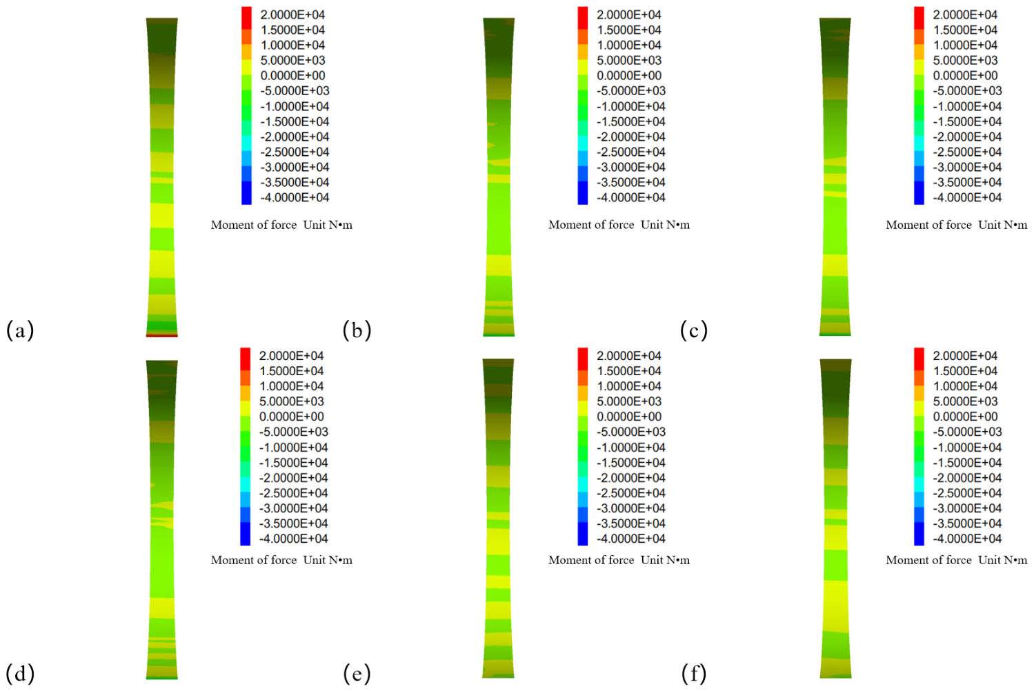
The response law of bending moment and axial force to buried depth is similar to that of displacement. Under the unreinforced condition, with the increase in buried depth, the peak bending moment at the vault increases slightly; for example, the vault bending moment at 200 m burial depth is about 25% higher than that at 50 m. The CFRP-reinforced cases show a lower concentration of the bending-moment field than their corresponding unreinforced cases, but the manuscript now treats this as a paired numerical observation rather than assuming a quantified homogenization coefficient. The accompanying load-transfer results provide stronger quantitative support for the CFRP mechanism: the surrounding-rock load-sharing ratio increases from about 0.70–0.82 in the unreinforced cases to about 0.85–0.90 after CFRP reinforcement. This simultaneous increase in surrounding-rock participation and reduction in deformation demonstrates that the CFRP layer modifies the force-transfer path under deep burial rather than merely stiffening the lining locally (Table 8).
The dynamic stability of the structure under cyclic internal pressure depends on the matching relationship between the residual stress field and the yield condition. Taking the buried depth of 200 m as an example, under the unreinforced condition, when the internal pressure is unloaded from 10 MPa to 4 MPa, there is obvious residual tensile stress concentration on the inner surface of the lining. After adding the CFRP layer, the residual stress distribution is more uniform, and the peak value is reduced by about 30%, which significantly improves the cyclic stability limit of the structure. The residual tensile stress is defined as the stress state after unloading from 10 MPa to 4 MPa. The 30% reduction refers to the peak residual tensile stress compared with the unreinforced case at the same pressure. It is not a measure of fatigue damage. The plastic zone indicates the extent of yielding in the surrounding rock but does not directly represent crack propagation, stiffness loss or fatigue life. Due to computational resource constraints, the accumulated plastic strain and load–unload curves are not extracted in the present study. This limitation is stated in the discussion section.
Table 8.
Quantitative load-sharing comparison for surrounding rock and CFRP.
The dynamic stability of the structure under cyclic internal pressure depends on the matching relationship between the residual stress field and the yield condition. Through its high tensile strength and fatigue resistance, the CFRP layer effectively suppresses the occurrence of reverse yield during the unloading stage. Taking the buried depth of 200 m as an example, under the unreinforced condition, when the internal pressure is unloaded from 10 MPa to 4 MPa, there is an obvious residual tensile stress concentration on the inner surface of the lining. After adding the CFRP layer, the residual stress distribution is more uniform, and the peak value is reduced by about 30%, which significantly improves the cyclic stability limit of the structure (Figure 8 and Figure 9).
For deep-buried caverns, the use of a CFRP composite lining can effectively balance the coupling effect of high initial ground stress and alternating internal pressure and improve the long-term stability of the structure.
Figure 8.
Comparison of axial force of carbon fiber lining with or without carbon fiber lining at different buried depths. (a) Buried depth of 50 m without carbon fiber lining, (b) buried depth of 150 m without carbon fiber lining, (c) buried depth of 250 m without carbon fiber lining, (d) buried depth of 50 m plus carbon fiber lining, (e) buried depth of 150 m plus carbon fiber lining, (f) buried depth of 250 m plus carbon fiber lining.
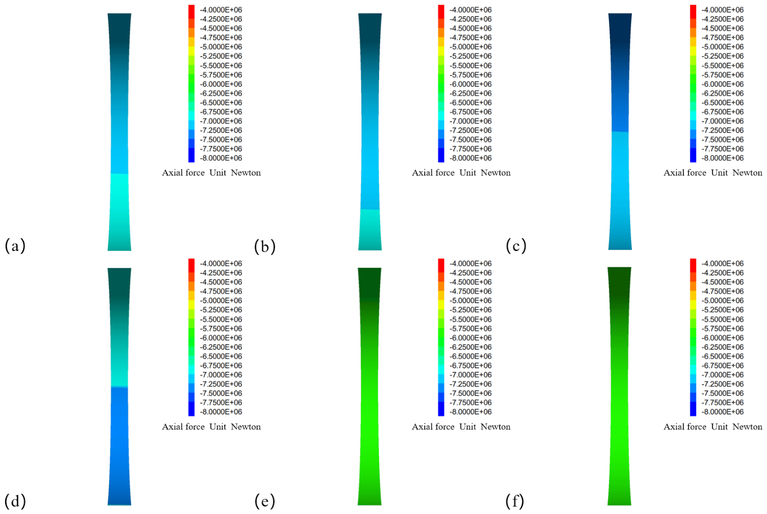
Figure 9.
Comparison of bending moment of carbon fiber lining with or without carbon fiber lining at different buried depths. (a) Buried depth of 50 m without carbon fiber lining, (b) buried depth of 150 m without carbon fiber lining, (c) buried depth of 250 m without carbon fiber lining, (d) buried depth of 50 m plus carbon fiber lining, (e) buried depth of 150 m plus carbon fiber lining, (f) buried depth of 250 m plus carbon fiber lining.
4.3. Analysis of the Influence of Surrounding Rock Grade
The grade of the surrounding rock is a comprehensive index to determine the mechanical parameters of surrounding rock, such as deformation modulus E, cohesion c and internal friction angle φ, which directly reflects the bearing capacity of the surrounding rock itself. In this study, the structural stability of the surrounding rock from grade I to grade V with or without a CFRP layer was compared and analyzed under the condition of 10 m diameter and 150 m buried depth.
4.3.1. The Influence of Surrounding Rock Grade on Displacement and Plastic Zone
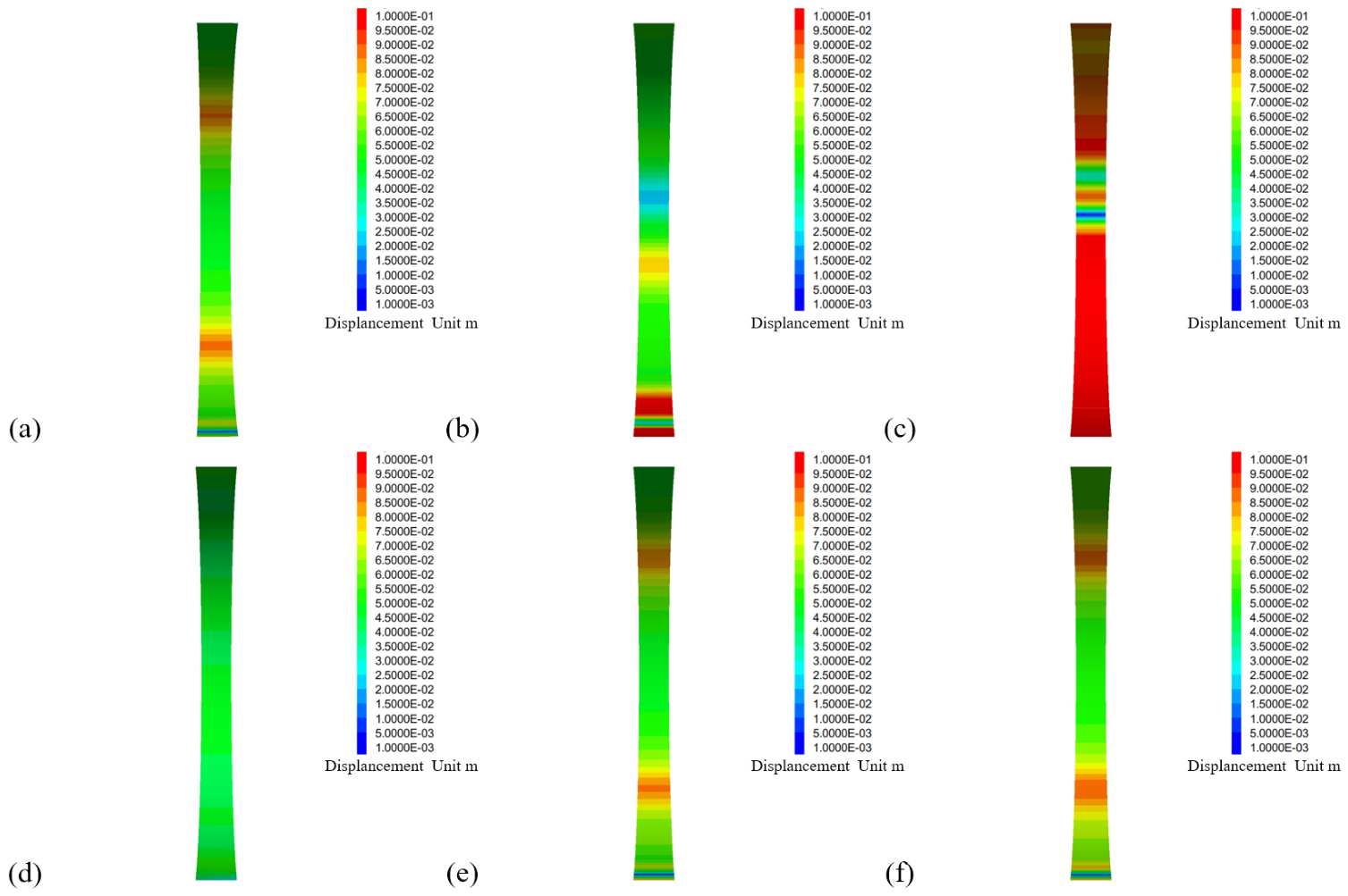
The simulation results show that the higher the grade of the surrounding rock, such as grade I and grade II surrounding rock, the greater the stiffness of the surrounding rock itself, and the stronger the constraint on the lining. Taking 10 MPa internal pressure as an example, under the unreinforced condition, the grade I surrounding rock E = 34 GPa, c = 2.2 MPa, the displacement is 0.10 mm, and the plastic zone is limited to the vicinity of the interface between the lining and the surrounding rock, while the grade V surrounding rock E = 1 GPa, c = 0.13 MPa, the displacement is also 0.10 mm, but the outer radius of the plastic zone is 2.5 times the cavern radius, which is much larger than the plastic zone thickness of 0.5R beyond the cavern wall for grade I surrounding rock. The plastic zone radius is defined as the outer radius of the yielded zone measured from the cavern center. The plastic zone is not circular due to the anisotropic in-situ stress. Due to computational resource constraints, the plastic zone extents in different directions and the plastic zone area are not extracted in the present study. This limitation is stated in the discussion section. This shows that the weak surrounding rock is more prone to plastic failure under load and is more dependent on the lining structure.
The improvement effect of a CFRP layer on low-grade surrounding rock is particularly prominent. In the V-grade surrounding rock, after adding the CFRP layer, the displacement of the cavern decreases from 0.10 mm to 0.08 mm, a decrease of 20%, the radius of the plastic zone decreases by about 30%, and the plastic strain distribution is more uniform, as shown in Figure 10. This shows that the CFRP layer makes up for the deficiency of the bearing capacity of the weak surrounding rock and transfers part of the internal pressure load to the deeper rock mass through the lining, which improves the stress state of the surrounding rock.
Figure 10.
Comparison of displacement nephograms of different surrounding rock grades with or without carbon fiber lining. (a) Surrounding rock grade I without carbon fiber lining, (b) surrounding rock grade III without carbon fiber lining, (c) surrounding rock grade V without carbon fiber lining, (d) surrounding rock grade I with carbon fiber lining, (e) surrounding rock grade III with carbon fiber lining, (f) surrounding rock grade V with carbon fiber lining.
4.3.2. Load-Sharing Mechanism of Surrounding Rock-Lining
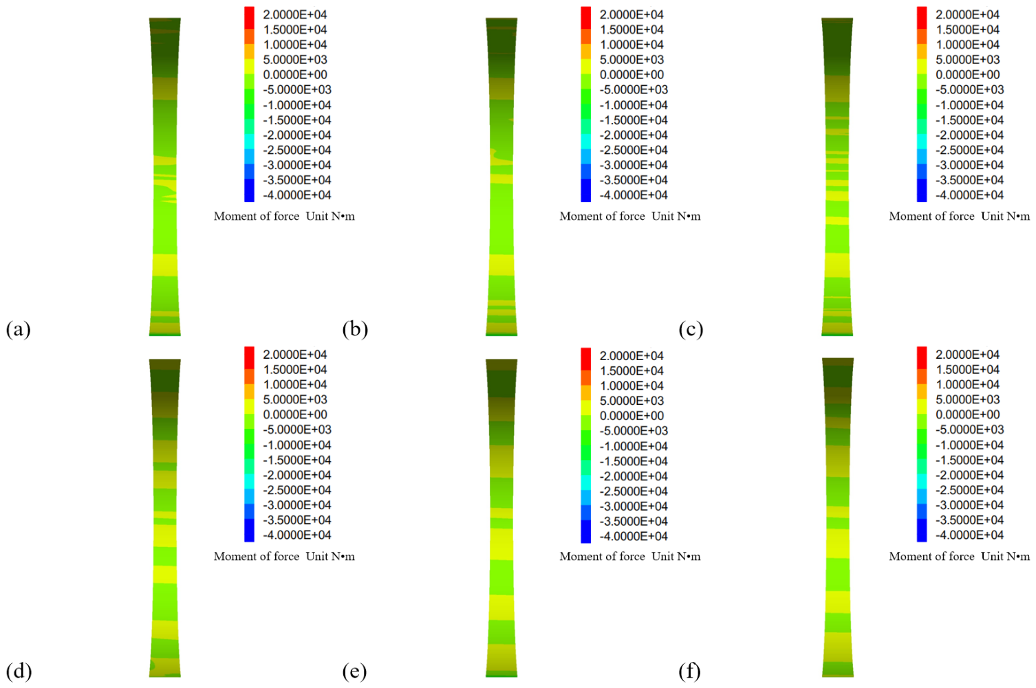
Figure 11 and Figure 12 show the axial-force and bending-moment distributions, respectively, for the cases with and without CFRP reinforcement in different surrounding rock grades. The influence of surrounding rock grade on the internal force of the lining is reflected in a clear change in load-sharing ratio (Figure 11 and Figure 12). In grade I surrounding rock, the surrounding rock carries about 0.45 of the radial load, whereas in grade V surrounding rock, this value decreases to about 0.12, indicating a strong shift of demand toward the lining as the rock mass weakens. These values are section-level load-sharing ratios, not global averages. Due to computational resource constraints, the integral quantities Q_total, Q_tining, Q_ SR and Q_CFRP are not calculated in the present study. This limitation is stated in the discussion section. The paired CFRP simulations show that the reinforcement partly reverses this unfavorable redistribution. In grade V surrounding rock, the CFRP layer carries about 40% of the circumferential axial force, while the tensile level of the concrete lining decreases by about 35%. The results therefore provide a direct numerical linkage between the added CFRP layer, the layer-level force partition, and the reduction in concrete tensile demand.
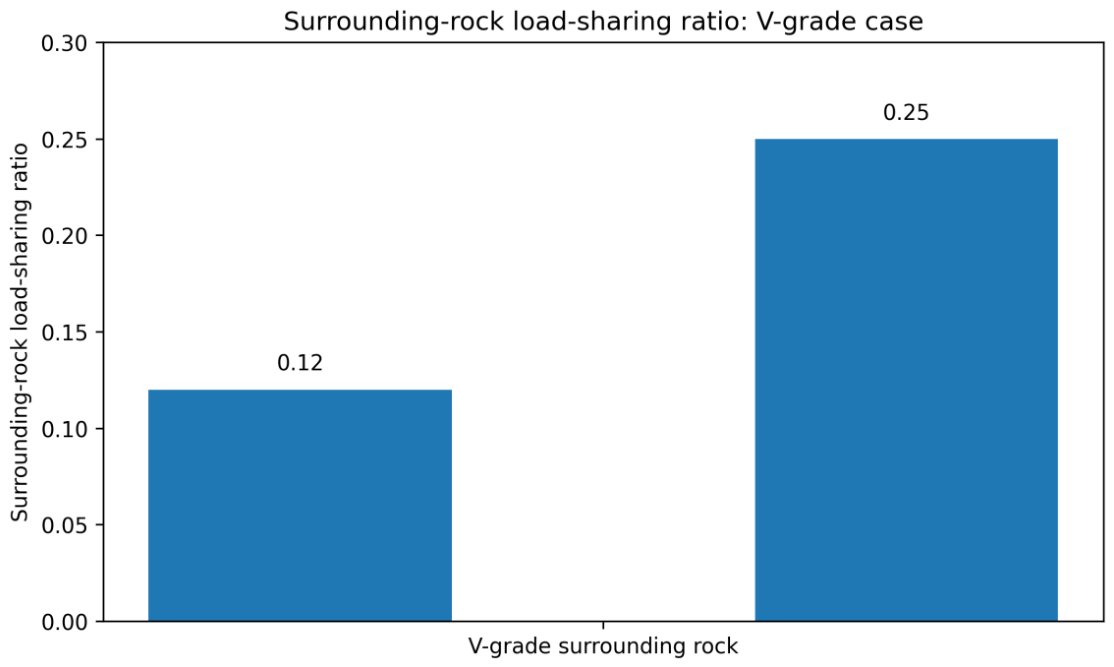
The CFRP layer plays a key reinforcing role under weak surrounding-rock conditions. The direct comparison of the stress field and force partition indicates that CFRP does not simply reduce displacement; it introduces an additional high-stiffness load path. In grade V surrounding rock, the CFRP axial-force share is about 40%, while the concrete tensile level decreases by about 35%. At the same time, the surrounding-rock load-sharing ratio increases from 0.12 to 0.25 after reinforcement. These results are mutually consistent: the CFRP layer attracts circumferential tensile force, lowers the demand on the concrete lining, and allows a larger fraction of the total pressure-related load to be carried by the surrounding rock. The conclusion about the role of CFRP is therefore based on direct paired changes in stress and load-sharing quantities rather than on material-property arguments alone.
The influence mechanism of surrounding rock grade on structural stability can be attributed to the matching relationship of the surrounding rock lining stiffness. The CFRP layer effectively adjusts the stiffness matching of the surrounding rock lining system through its high elastic modulus and reasonable laying method, so that the load can be better distributed between the two. Studies have shown that a CFRP composite lining can effectively broaden the adaptability of artificial caverns to surrounding rock conditions, making it possible to build large CAES gas storage facilities in surrounding rocks of grade III and below. However, for extremely weak strata such as grade V surrounding rock, it is still necessary to cooperate with other reinforcement measures to ensure long-term operation safety.
Figure 11.
Comparison of axial force of carbon fiber lining with or without carbon fiber lining in different surrounding rock grades. (a) Surrounding rock grade I without carbon fiber lining, (b) surrounding rock grade III without carbon fiber lining, (c) surrounding rock grade V without carbon fiber lining, (d) surrounding rock grade I with carbon fiber lining, (e) surrounding rock grade III with carbon fiber lining, (f) surrounding rock grade V with carbon fiber lining.
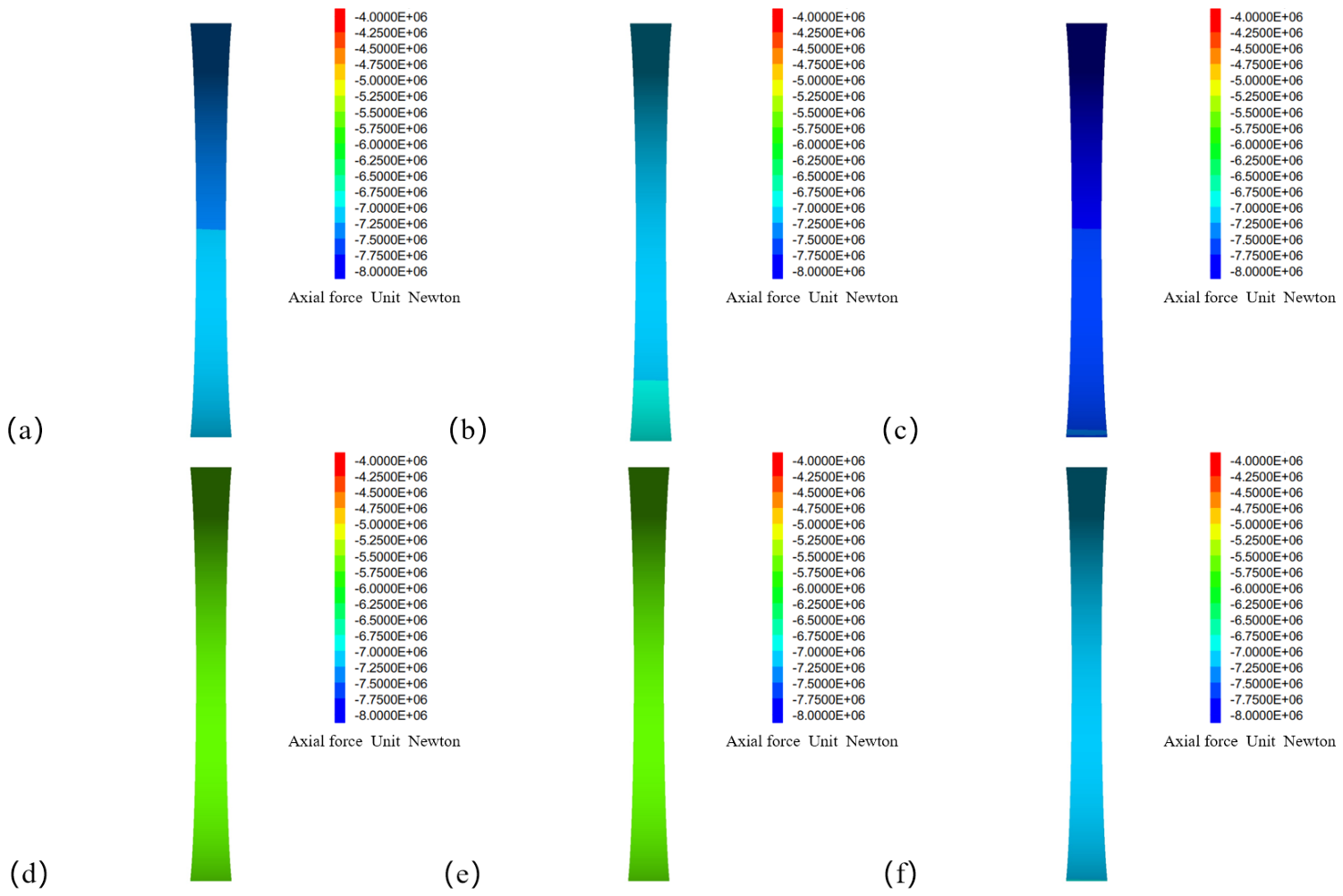
Figure 12.
Comparison of bending moment of carbon fiber lining with or without carbon fiber lining in different surrounding rock grades. (a) Surrounding rock grade I without carbon fiber lining, (b) surrounding rock grade III without carbon fiber lining, (c) surrounding rock grade V without carbon fiber lining, (d) surrounding rock grade I with carbon fiber lining, (e) surrounding rock grade III with carbon fiber lining, (f) surrounding rock grade V with carbon fiber lining.
5. Discussion
In this study, a functional layered integrated composite lining system composed of a steel lining, carbon fiber sheet CFRP and reinforced concrete is proposed and systematically verified. This system breaks through the design limitation of traditional single-material lining and introduces the theory of a composite laminated plate and the concept of structural cooperative work into the design framework of an underground pressure vessel lining. The core mechanism is the load distribution determined by strain compatibility and stiffness ratio. The steel lining ensures absolute sealing, the CFRP layer specifically bears the circumferential tension, and the reinforced concrete layer provides the main bearing and long-term durability. The high-performance bonding technology is used to achieve synchronous deformation between the layers to form an integral pressure-bearing ring structure. The overall effect enhances the dynamic stability of the composite lining under alternating internal pressure.
The numerical results quantify the reinforcement effect through direct paired comparisons of stress and load partition (Figure 13). For the investigated cases, CFRP carries about 30–50% of the circumferential axial force. In the 12 m diameter case, the peak circumferential tensile stress in the surrounding rock decreases by about 18%, while in grade V surrounding rock the CFRP share is about 40%, the concrete tensile level decreases by about 35% and the surrounding-rock load-sharing ratio increases from 0.12 to 0.25 (Figure 14). The deep-burial cases show the same mechanism: the surrounding-rock load-sharing ratio increases from about 0.70–0.82 without CFRP to about 0.85–0.90 with CFRP, while the peak residual tensile stress at 200 m burial depth decreases by about 30%. These paired results support the conclusion that CFRP modifies the force-transfer path and stress state of the composite system. With respect to bending moment, the revised interpretation is deliberately limited to the reduction in spatial concentration observed in the paired numerical fields; a quantitative uniformity coefficient is not reported because the full circumferential M(θ) dataset is not available in the present study.
This study systematically compares cavern diameter, buried depth and surrounding rock grade using paired models with and without CFRP. The principal conclusion is now stated in terms of directly observed response changes. In the large-diameter case, the 20 m cavern shows a 10% displacement reduction after CFRP reinforcement, compared with 6.25% for the 8 m cavern. In the 250 m deep cavern, the vault displacement decreases by 20%, while the surrounding-rock load-sharing ratio over the investigated depth range increases from about 0.70–0.82 without CFRP to about 0.85–0.90 with CFRP. In grade V surrounding rock, the displacement decreases by 20%, the plastic-zone radius decreases by about 30%, the CFRP layer carries about 40% of the circumferential axial force, the concrete tensile level decreases by about 35%, and the surrounding-rock load-sharing ratio increases from 0.12 to 0.25. These paired stress and load-sharing changes provide the numerical basis for attributing the observed stability improvement to CFRP-mediated load redistribution. The evidence for bending-moment homogenization is more limited and is therefore described as reduced spatial concentration rather than as a quantified uniformity effect.
This study is based on several idealizations. The material is treated as continuous and isotropic or orthotropic as appropriate, and perfect bonding is assumed at the idealized interfaces. The excavation and lining sequence is represented by a zero-relaxation, simultaneous-support condition, because staged construction data are not available in the present study. The thermal field is prescribed as constant, so temperature-induced strain and stress are not included. The plastic response of the surrounding rock is described using the Mohr–Coulomb criterion. These assumptions define the scope of the present mechanical analysis and should not be interpreted as evidence that construction sequencing or thermal effects are negligible in actual CAES operation. In particular, the present results establish the mechanical role of CFRP under the prescribed plane-strain and thermal conditions, while the influence of staged excavation, measured temperature histories, interface degradation and long-term thermo-mechanical cycling remains to be quantified in future work.
Figure 13.
Quantitative paired comparison of stress-related indicators (unreinforced case normalized to 100%).
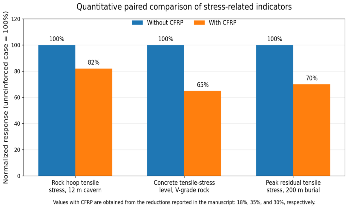
Figure 14.
Surrounding-rock load-sharing ratio for the V-grade representative case.
6. Conclusions
In this study, the theoretical framework of static and dynamic stability analysis of a CFRP composite lining structure of a compressed air energy storage artificial cavern under non-hydrostatic stress is established by combining the complex variable function method with the elastic–plastic stability theory. The framework overcomes the limitations of the traditional thick-walled cylinder model in describing the interaction of the surrounding rock lining in a non-uniform ground stress field and provides a theoretical basis for the optimal design of a CFRP-reinforced lining in a complex geological environment. The main conclusions are as follows:
- (1)
- The buried depth of the cavern, the grade of the surrounding rock and the diameter of the cavern are the dominant factors affecting the static stability of the composite lining. Direct paired simulations show that CFRP carries a significant share of the circumferential axial force, in the range of 30–50% at the section level. In grade V surrounding rock, the CFRP share is about 40%, the concrete tensile level decreases by about 35%, and the surrounding-rock load-sharing ratio increases from 0.12 to 0.25. In the 12 m diameter case, the peak elastic circumferential stress in the surrounding rock decreases by about 18% after CFRP reinforcement. These results demonstrate that the reinforcement effect is associated with measurable load redistribution and stress-field modification. The peak residual tensile stress is reduced by about 30%, and the plastic-zone radius is reduced by more than 25% in the reported cases. These values are section-level observations and should be interpreted within the scope of the prescribed assumptions in the reported cases, indicating improved resistance to cyclic loading under the prescribed mechanical conditions;
- (2)
- The CFRP reinforcement effect is particularly significant under unfavorable geological conditions. In the V-class surrounding rock, the displacement decreases by 20%, the plastic-zone radius decreases by about 30%, and the CFRP layer carries a significant share of the circumferential axial force, about 40% at the section level. In the 20 m diameter cavern, the displacement decreases by 10%. The bending-moment results are interpreted as a reduction in spatial concentration of the moment field; a formal uniformity coefficient is not reported because the full circumferential moment dataset is not available in the present study. These paired changes in deformation, stress and load partition provide the numerical basis for the stated CFRP reinforcement effect. The bending-moment results are interpreted as a reduction in spatial concentration of the moment field; a formal uniformity coefficient is not reported because the full circumferential moment dataset is not available in the present study;
- (3)
- The ratio of in-situ stress and internal pressure is introduced as a dimensionless evaluation index for the optimization of cavern layout. The research shows that the combination of high ground stress and internal pressure ratio with a large lateral pressure coefficient can significantly improve the dynamic stability limit of the structure, but it is necessary to pay attention to the plastic yield risk under low internal pressure or zero internal pressure conditions. The ratio of in-situ stress to internal pressure is introduced as a dimensionless evaluation index for the optimization of cavern layout. The research shows that the combination of high ground stress and internal pressure ratio with a large lateral pressure coefficient can significantly improve the dynamic stability limit of the structure, but it is necessary to pay attention to the plastic yield risk under low internal pressure or zero internal pressure conditions. The present study focuses on the structural response of the cavern lining. The suggestion of multiple smaller caverns is based on the observed trend of reduced stress and displacement with a decreasing diameter. However, an economic comparison requires the same storage capacity, cavern spacing, access requirements, and construction costs, which are not analyzed in this study. Therefore, the conclusion is limited to the structural trend, and no economic claim is made;
- (4)
- The conclusion of this paper is based on the assumption of homogeneous surrounding rock and perfect interface bonding, which is suitable for geological conditions with good rock mass integrity. The interface durability and long-term service performance of CFRP reinforcement still need to be further verified by a field test and a multi-field coupling analysis. The present study is based on a constant thermal condition, perfect interface bonding, and a zero-relaxation excavation-support sequence. These assumptions define the scope of the present mechanical analysis. The thermal sensitivity of the CFRP-reinforced lining, the effect of staged construction, and the progressive damage of CFRP should be evaluated in future work using measured or thermodynamically predicted temperature histories and advanced material models.
Author Contributions
Conceptualization, J.Z. and Y.S.; methodology, M.C.; software, B.W.; validation, B.W., R.Z. and W.W.; formal analysis, B.W.; investigation, W.W.; resources, J.Z.; data curation, B.W.; writing—original draft preparation, B.W.; writing—review and editing, R.Z.; supervision, W.W.; project administration, J.Z. All authors have read and agreed to the published version of the manuscript.
Funding
This research received no external funding.
Data Availability Statement
The original contributions presented in this study are included in the article. Further inquiries can be directed to the corresponding author.
Conflicts of Interest
Author Jie Zhu, Yiwei Song, Meng Cui were employed by the company China Petroleum Engineering Construction & Corp North China Company Renqiu Hebei, China, Renqiu Hebei, China. The remaining authors declare that the research was conducted in the absence of any commercial or financial relationships that could be construed as potential conflicts of interest.
References
- Dhabi, A. Renewable Capacity Statistics 2024; International Renewable Energy Agency (IRENA): Masdar City, Abu Dhabi, United Arab Emirates, 2024. [Google Scholar]
- Sarmast, S.; Rounidej, K.; Fraser, R.A.; Duseault, M.B. Optimizing near-adiabatic compressed air energy storage (NA-CAES) systems: Sizing and design considerations. Appl. Energy 2024, 357, 122465. [Google Scholar] [CrossRef] [Scilit]
- Li, P.; Hu, Q.; Han, Z.; Wang, C.; Wang, R.; Han, X.; Wang, Y. Thermodynamic analysis and multi-objective optimization of a trigenerative system based on compressed air energy storage under different working media and heating storage media. Energy 2022, 239, 122252. [Google Scholar] [CrossRef] [Scilit]
- Zhang, X.; Gao, Z.; Zhou, B.; Guo, H.; Xu, Y.; Ding, Y.; Chen, H. Advanced compressed air energy storage systems: Fundamentals and applications. Engineering 2024, 34, 246–269. [Google Scholar] [CrossRef] [Scilit]
- Xu, Y.; Wang, X.; Zhang, J.; Zhang, H.; Yang, F.; Yan, D.; Liang, J.; Yang, H.; Wang, Y. Experimental investigation and artificial neural network prediction of small-scale compressed air energy storage system based on pneumatic motor. Therm. Sci. Eng. Prog. 2024, 47, 102287. [Google Scholar] [CrossRef] [Scilit]
- Chen, L.; Zheng, T.; Mei, S.; Xue, X.; Liu, B.; Lu, Q. Review and prospect of compressed air energy storage system. J. Mod. Power Syst. Clean Energy 2016, 4, 529–541. [Google Scholar] [CrossRef] [Scilit]
- Budt, M.; Wolf, D.; Span, R.; Yan, J. A review on compressed air energy storage: Basic principles, past milestones and recent developments. Appl. Energy 2016, 170, 250–268. [Google Scholar] [CrossRef] [Scilit]
- Bazdar, E.; Sameti, M.; Nasiri, F.; Haghighat, F. Compressed air energy storage in integrated energy systems: A review. Renew. Sustain. Energy Rev. 2022, 167, 112701. [Google Scholar] [CrossRef] [Scilit]
- Chen, L.; Zhang, L.; Wang, Y.; Xie, M.; Yang, H.; Ye, K.; Mohtaram, S. Design and performance evaluation of a novel system integrating water-based carbon capture with adiabatic compressed air energy storage. Energ. Conver. Manag. 2023, 276, 116583. [Google Scholar] [CrossRef] [Scilit]
- Xiang, L.; Hu, P.; Chen, C.; Zhang, N.; Na, M.; Xiang, F. Thermodynamic analysis of three ejector based organic flash cycles for low grade waste heat recovery. Energ. Conver. Manag. 2019, 185, 384–395. [Google Scholar] [CrossRef] [Scilit]
- He, W.; Luo, X.; Evans, D.; Busby, J.; Garvey, S.; Parkes, D.; Wang, J. Energy storage of compressed air in cavern and cavern volume estimation of the large-scale compressed air energy storage system. Appl. Energy 2017, 208, 745–757. [Google Scholar] [CrossRef] [Scilit]
- Wang, S.; Zhang, X.; Yang, L.; Zhou, Y.; Wang, J. Experimental study of compressed air energy storage system with thermal energy storage. Energy 2016, 103, 182–191. [Google Scholar] [CrossRef] [Scilit]
- Kim, Y.M.; Shin, D.G.; Favrat, D. Operating Characteristics of Constant-Pressure Compressed Air Energy Storage (CAES) System Combined with Pumped Hydro Storage Based on Energy and Exergy Analysis. Energy 2011, 36, 6220–6233. [Google Scholar] [CrossRef] [Scilit]
- Schmidt, F.; Menendez, J.; Konietzky, H.; Pascual-Munoz, P.; Castro, J.; Loredo, J.; Sanchez, A.B. Converting closed mines into giant batteries: Effects of cyclic loading on the geomechanical performance of underground compressed air energy storage systems. J. Energy Storage 2020, 32, 101882. [Google Scholar] [CrossRef] [Scilit]
- de Prado, L.A.; Menendez, J.; Bernardo-Sanchez, A.; Galdo, M.; Loredo, J.; Fernandez-Oro, J.M. Thermodynamic Analysis of Compressed Air Energy Storage (CAES) Reservoirs in Abandoned Mines Using Different Sealing Layers. Appl. Sci. 2021, 11, 2573. [Google Scholar] [CrossRef] [Scilit]
- Bu, X.; Huang, S.; Liu, S.; Yang, Y.; Shu, J.; Tan, X.; Chen, H.; Wang, G. Efficient utilization of abandoned mines for isobaric compressed air energy storage. Energy 2024, 311, 133392. [Google Scholar] [CrossRef] [Scilit]
- Khaledi, K.; Mahmoudi, E.; Datcheva, M.; Schanz, T. Analysis of compressed air storage caverns in rock salt considering thermo-mechanical cyclic loading. Environ. Earth Sci. 2016, 75, 1149. [Google Scholar] [CrossRef] [Scilit]
- Menendez, J.; Fernandez-Oro, J.M.; Galdo, M.; Alvarez, L.; Bernardo-Sanchez, A. Numerical investigation of underground reservoirs in compressed air energy storage systems considering different operating conditions: Influence of thermodynamic performance on the energy balance and round-trip efficiency. J. Energy Storage 2022, 46, 103816. [Google Scholar] [CrossRef] [Scilit]
- Kushnir, R.; Dayan, A.; Ullmann, A. Temperature and pressure variations within compressed air energy storage caverns. Int. J. Heat Mass Transf. 2012, 55, 5616–5630. [Google Scholar] [CrossRef] [Scilit]
- Jiang, Z.; Li, P.; Tang, D.; Zhao, H.; Li, Y. Experimental and numerical investigations of small-scale lined rock cavern at shallow depth for compressed air energy storage. Rock Mech. Rock. Eng. 2020, 53, 2671–2683. [Google Scholar] [CrossRef] [Scilit]
- Schmidt, F.; Menendez, J.; Konietzky, H.; Jiang, Z.; Fernandez-Oro, J.M.; Alvarez, L.; Bernardo-Sanchez, A. Technical feasibility of lined mining tunnels in closed coal mines as underground reservoirs of compressed air energy storage systems. J. Energy Storage 2024, 78, 110055. [Google Scholar] [CrossRef] [Scilit]
- Liu, W.; Li, Q.; Yang, C.; Shi, X.; Wan, J.; Jurado, M.J.; Li, Y.; Jiang, D.; Chen, J.; Qiao, W.; et al. The role of underground salt caverns for large-scale energy storage: A review and prospects. Energy Storage Mater. 2023, 63, 103045. [Google Scholar] [CrossRef] [Scilit]
- Hydrostor-Long Duration Energy Storage Developer. 2024. Available online: https://hydrostor.ca/projects/ (accessed on 1 November 2026).
- Xu, W.; Garvey, S.D.; Ren, T.; Hu, Y. Dynamics of Dissolution for Underwater Compressed Air Energy Storage. In 2019 Offshore Energy Storage Summit; IEEE: New York, NY, USA, 2019; pp. 1–5. [Google Scholar]
- Costa, E.M.; Dedavid, B.A.; Santos, C.A.; Lopes, N.F.; Fraccaro, C.; Pagarantidis, T.; Lovatto, L.P. Crevice corrosion on stainless steels in oil and gas industry: A review of techniques for evaluation, critical environmental factors and dissolved oxygen. Eng. Fail. Anal. 2023, 144, 106955. [Google Scholar] [CrossRef] [Scilit]
- Liu, S.H.; Zhang, D. Study on Long-Term Stability of Lined Rock Cavern for Compressed Air Energy Storage. Energies 2024, 17, 5908. [Google Scholar] [CrossRef] [Scilit]
- Xu, Y.J.; Xia, C.C.; Zhou, C.H.; Zhang, S.S. An Analytical Solution for Elastoplastic Responses of a Lined Rock Cavern for Compressed Air Energy Storage Considering Excavation and High Internal Pressure. Comput. Geotech. 2024, 170, 105261. [Google Scholar] [CrossRef] [Scilit]
- Li, Y.Y.; Zhou, C.H.; Zhang, Z.H.; Li, X.; Peng, Y.L.; Xia, C.H. Mechanical Response of Engineered Cementitious Composite/Fiber-Reinforced Polymer-Filled Concrete Composite Lining for Compressed Air Energy Storage Underground Caverns. Tunn. Constr. 2026, 46, 1511–1521. [Google Scholar]
- Xiang, Y.; Zhang, G.; Wang, X.; Zhang, G.; Xiong, F.; Tang, Z.; Hua, D. Load-sharing characteristics of lined rock caverns of compressed air energy storage system: A theoretical analysis. Appl. Energy 2025, 388, 125626. [Google Scholar] [CrossRef] [Scilit]
- Mu, L.; Hou, Y.; Cheng, L.; Xia, C.; Xu, C.; Cen, D.; Chen, R.; Molina, A.G.-F.; Rodriguez-Dono, A. Interaction between segmented lining and surrounding rock considering sliding layer for compressed air energy storage caverns. Tunn. Undergr. Space Technol. 2026, 172, 107575. [Google Scholar] [CrossRef] [Scilit]
- Sun, Z.; Zhao, C.; Qian, Y.; Xing, J.; Luo, Q. Section shape optimization method for artificial compressed air energy storage chambers: An exploration of elliptical section stability. J. Energy Storage 2026, 144, 119596. [Google Scholar] [CrossRef] [Scilit]
- Li, H.; Ma, H.; Liang, W.; Zeng, Z.; Fang, J.; Wang, X.; Liu, Y.; Liang, R.; Yang, C. Stability assessment of CAES salt caverns using a fractal-order derivative creep-fatigue damage model. Energy 2025, 317, 134584. [Google Scholar] [CrossRef] [Scilit]
- Jin, S.; Xia, C.; Lv, Z.; Ye, Y. Theoretical analysis of underground artificial caverns layout design for compressed air energy storage based on surrounding rock-lining stability and shakedown. Tunn. Undergr. Space Technol. 2026, 168, 107200. [Google Scholar] [CrossRef] [Scilit]
Disclaimer/Publisher’s Note: The statements, opinions and data contained in all publications are solely those of the individual author(s) and contributor(s) and not of MDPI and/or the editor(s). MDPI and/or the editor(s) disclaim responsibility for any injury to people or property resulting from any ideas, methods, instructions or products referred to in the content. |
© 2026 by the authors. Licensee MDPI, Basel, Switzerland. This article is an open access article distributed under the terms and conditions of the Creative Commons Attribution (CC BY) license.